
 Open Access Article
 This Open Access Article is licensed under a Creative Commons Attribution-Non Commercial 3.0 Unported Licence
Sector coupling via hydrogen to lower the cost of energy system decarbonization†
Guannan
He
 *a,
Dharik S.
Mallapragada
a,
Abhishek
Bose
a,
Clara F.
Heuberger-Austin
b and
Emre
Gençer
a
*a,
Dharik S.
Mallapragada
a,
Abhishek
Bose
a,
Clara F.
Heuberger-Austin
b and
Emre
Gençer
a
aMIT Energy Initiative, Massachusetts Institute of Technology, Cambridge, MA, USA. E-mail: gnhe@mit.edu
bShell Global Solutions International B. V., Shell Technology Centre Amsterdam, 1031 HW Amsterdam, The Netherlands
First published on 4th August 2021
Abstract
There is growing interest in using hydrogen (H2) as a long-duration energy storage resource in a future electric grid dominated by variable renewable energy (VRE) generation. Modeling H2 use exclusively for grid-scale energy storage, often referred to as “power-to-gas-to-power (P2G2P)”, overlooks the cost-sharing and CO2 emission benefits from using the deployed H2 assets to decarbonize other end-use sectors where direct electrification is challenging. Here, we develop a generalized framework for co-optimizing infrastructure investments across the electricity and H2 supply chains, accounting for the spatio-temporal variations in energy demand and supply. We apply this sector-coupling framework to the U.S. Northeast under a range of technology cost and carbon price scenarios and find greater value of power-to-H2 (P2G) vs. P2G2P routes. Specifically, P2G provides grid flexibility to support VRE integration without the round-trip efficiency penalty and additional cost incurred by P2G2P routes. This form of sector coupling leads to: (a) VRE generation increase by 13–56%, and (b) total system cost (and levelized costs of energy) reduction by 7–16% under deep decarbonization scenarios. Both effects increase as H2 demand for other end-uses increases, more than doubling for a 97% decarbonization scenario as H2 demand quadruples. We also find that the grid flexibility enabled by sector coupling makes deployment of carbon capture and storage (CCS) for power generation less cost-effective than its use for low-carbon H2 production. These findings highlight the importance of using an integrated energy system framework with multiple energy vectors in planning cost-effective energy system decarbonization.
Broader contextDeep decarbonization of energy systems is imperative to address climate change. Hydrogen could play a significant role in cost-effectively reducing CO2 emissions from certain end-uses where direct electrification is challenging. Here, we develop a scalable decision-support framework for assessing the costs and technology choices for the decarbonization of the power sector and one or more end-use sectors such as transport, industry, and buildings. This framework provides a systematic way to study the role and impact of hydrogen based technology pathways in a future low-carbon, integrated energy system, while accounting for interactions within and between supply chains of end-use fuels (electricity and hydrogen in this case). Our numerical experiments with the framework reveal substantial cost saving and CO2 emission reduction benefits from coupling the power sector and other end-use sectors via the flexible production of hydrogen from electricity, which avoids the extra efficiency losses and capital cost of electricity storage mechanisms based on hydrogen as the storage medium. In such an integrated energy system, carbon capture and storage is also found to be more cost-effective for low-carbon hydrogen production rather than low-carbon electricity generation. The developed framework can be readily extended to include other end-use fuels (e.g. synthetic fuels) and other vectors (e.g. biomass, CO2) that could play a role in a low-carbon integrated energy system. |
1 Introduction
As the greenhouse gas (GHG) emission intensity of electricity generation in various regions has declined with continued adoption of wind and solar generation, there is growing interest to pursue electrification-centric decarbonization strategies for other end-use sectors where emissions reduction has been sluggish. Yet, direct electrification may be practically challenged for some of these end-uses, e.g., in the case of heavy-duty transport where volumetric energy density and refueling time are key drivers for fuel choice. In this context, hydrogen (H2) and H2 derived energy carriers are expected to play critical roles in the decarbonization of difficult-to-electrify end-uses in transport, building and industrial sectors.1 Decarbonizing these sectors via electricity or H2 use could potentially enable a more integrated energy system with potentials for cost-savings through increased asset utilization.2 The key advantage of sector coupling is rooted in the extra flexibility from end-use sectors to accommodate variable renewable energy (VRE) resources, directly via power or indirectly via H2.3 In addition to the plurality of its end-uses, the multiple technology choices across the H2 supply chain, from production, storage, transport and end-use, make its assessment a complex systems problem. Here, we propose a scalable decision-support framework for assessing the impact of technology and policy choices on the decarbonization of power sector in conjunction with other end-use sectors. This framework provides a systematic way to study the role and impact of H2-based technology pathways in a future low-carbon, integrated energy system at a regional/national scale.Recent renewed interest in H2 has been partially intrigued by expectations of a future VRE-dominant electric grid and cost declines for water electrolyzers,4 both of which raise the prospect of electrolytic H2 becoming cost-competitive with fossil fuel-based pathways, e.g., natural gas reforming.5,6 Besides the economics of electrolytic H2 production,7,8 many studies have focused on evaluating the economics of H2-based energy storage for the grid (power-to-gas-to-power, P2G2P), which relies on electrolysis for H2 production, under deep decarbonization scenarios. Some of the studies in this area focus on: (1) comparing the cost-effectiveness of P2G2P with other types of long-duration energy storage options like pumped hydro and compressed air energy storage for variable renewable energy (VRE) integration, from a marginal deployment perspective (i.e. electricity price taker),9–11 (2) assessing least-cost investment and operation of H2 storage and short-duration energy storage like lithium-ion batteries in the context of VRE dominant power systems,11–14 and (3) the operational scheduling of H2 storage in power markets.15,16 Although these studies provide useful insights to compare different energy storage technologies from the perspective of the power sector, they overlook the multiple potential uses of H2 (or H2 derived carriers) outside the power sector and the associated cost-savings resulting from sharing infrastructure costs across these uses. Consequently, in the absence of modeling cross-sectoral interactions, the role of H2 storage may be under-valued as compared to other long-duration storage technologies in future low-carbon power grids.17
With the above motivation, a number of studies have expanded the scope of traditional power sector capacity expansion models (CEM) to endogenize investment decisions in end-use technologies, which include some parts of the H2 supply chain, notably electrolytic H2 production. These studies highlight the potential for flexible electricity consumption in other end-uses to partially substitute the need for energy storage in the electricity sector and alter generation mix in the power sector towards increasing VRE deployment.18–21 While these studies are inspiring, the interactions between the H2 supply chain and the power sector, in many of the studies, exclude critical components in the H2 supply chain. For example, some studies ignore the possibility of natural gas-based H2 production from steam methane reformer (SMR) with or without carbon capture and storage (CCS).22–24 Second, most literature either do not consider some modes of H2 transmission22,25,26 or when it is included, the modeling of H2 transmission is oversimplified by setting fixed lower and upper H2 flow limits for each route.23–25,27 These approaches may not capture the potential benefits of both H2 pipeline and trucks serving as transmission and storage assets simultaneously. Notably, H2 trucks can function as mobile storage, which has been shown to provide greater operational flexibility than stationary storage.28 Moreover, the existing literature does not reveal a clear evolution of the role of H2 in energy systems as the costs of H2 infrastructure decline with increased adoption or technology innovation. Jacobson et al. (2019)29 proposes Green New Deal roadmaps for 143 countries and analyzes the cost-savings and job creations of the roadmaps, considering power-H2 coupling and H2 for transportation. Some of the key differences between this study and Jacobson et al. (2019)29 include the use of a multi-zone least-cost optimization model as well as the representation of hydrogen transmission (and storage) via trucks and pipelines to manage spatiotemporal variability in supply and demand. Fasihi et al. (2020)30 analyzes the levelized costs of baseload electricity and baseload hydrogen with 100% renewable energy, considering P2G2P. While it could be more valuable for 100% renewable energy systems,29,30 we show that the extra flexibility from sector-coupling still brings significant value even in case of deeply decarbonized systems that rely on sparing use of natural gas with or without CCS.
This paper develops a high-fidelity electricity-H2 capacity planning model, Decision Optimization of Low-Carbon Power-Hydrogen Network (DOLPHYN), to study the role of H2 in low-carbon energy systems, the sector-coupling effects, and the trade-offs between various technology options across the entire bulk supply chain‡ of both energy carriers. For a pre-defined set of electricity and H2 demand scenarios, the model determines the least-cost technology mix across the power and H2 sectors while adhering to operational constraints of the power and H2 supply chains at an hourly resolution along with the spatio-temporal variations in VRE supply and energy demands. We apply the DOLPHYN model to the U.S. Northeast energy system for a range of CO2 prices (up to $1000 per tonne CO2), H2 demand and technology cost scenarios, to analyze the interactions between the power and H2 supply chains, the sector-coupling benefits, and the role of H2 to serve as a flexible demand response or grid-scale energy storage for the power sector.
2 Methods
2.1 Model overview
The DOLPHYN model evaluates investments and operations across the bulk supply chain for electricity and H2, including production, storage, transmission, conditioning (compression/liquefaction in the case of H2) and demand as shown in Fig. 1. The model determines the least-cost mix of electricity and H2 production, storage, and transmission infrastructures to meet power and H2 demands subject to a variety of operational and policy constraints. The developed model can incorporate a wide range of power and H2 technology options, including VRE generation, carbon capture and storage (CCS) applied to power and H2 generation, and truck (gaseous, liquid) and pipelines for H2 transportation. The power systems and H2 supply chain are coupled primarily through electrolysis and power generation technologies fueled by H2, as well as electricity consumption in H2 compression/liquefaction. The key operational constraints of the model, implemented at an hourly resolution, include: (a) supply-demand balance for H2 and electricity at each zone, (b) inventory balance constraints for stationary storage technologies, (c) inventory balance constraints related to trucks at a given location (any of the zones and routes, arriving, departing or in transit) and for different states (empty and full), and (d) linearized unit commitment for conventional thermal power generation technologies and natural gas based H2 production technologies. We enforce the operational constraints at an hourly resolution over a set of representative weeks that are selected from applying time-series clustering to annual demand and VRE resource profile data,31 to approximate annual system operations. The time-domain reduction preserves chronological variability of energy demands and VRE resource availability, as well as the correlations among them, while reducing the model size to still be computationally tractable. Process level CO2 emissions are penalized with a price on emissions in both sectors. The details of the power system planning model and the H2 supply chain model can be referred to Jenkins and Sepulveda32 and He et al.,28 respectively. The model data inputs are available on GitHub,33 and the codes are being prepared for open-source release shortly.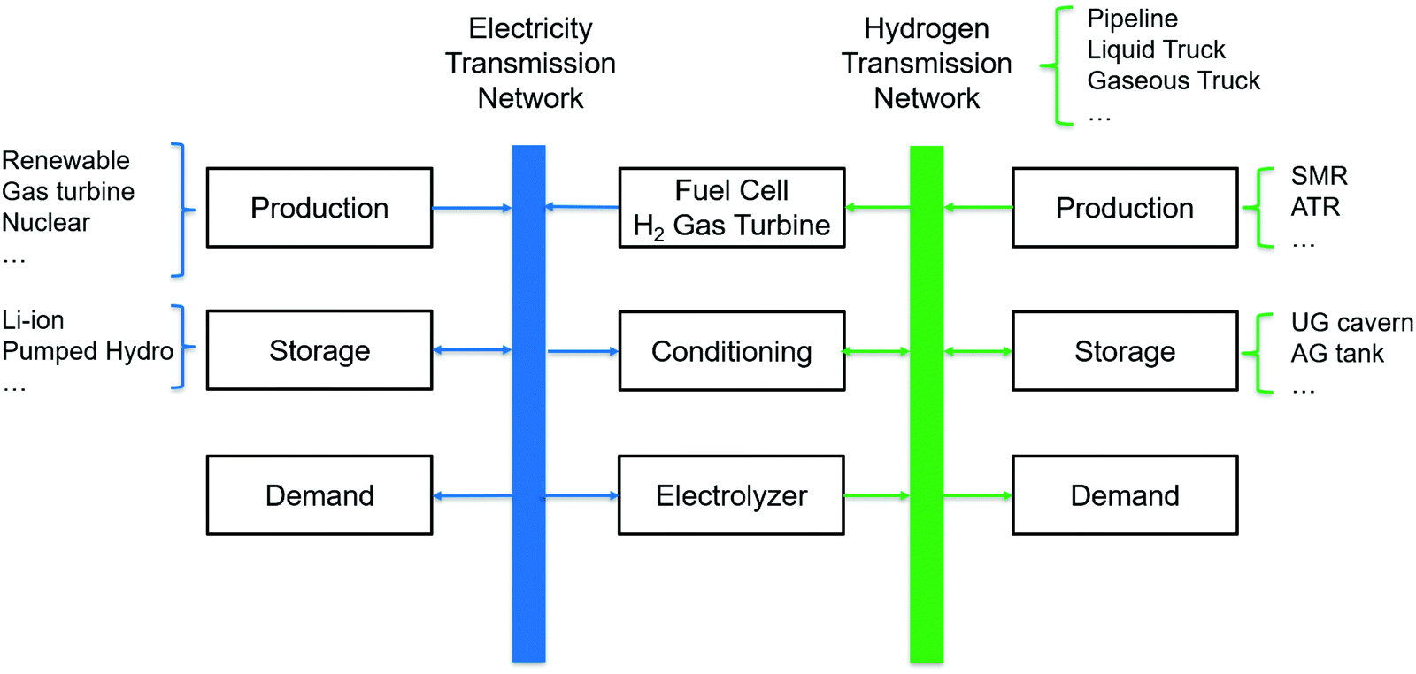 | ||
| Fig. 1 Superstructure of the coupled model of power systems and H2 supply chain. | ||
2.2 Case study setup
We illustrate the value of the proposed model using a case study where we assess electricity and H2 infrastructure outcomes for the U.S. Northeast region under a variety of demand, technology and CO2 price scenarios for 2050. We model a greenfield 2050 system with the exception of existing inter-zonal transmission, hydro power generation (both domestic and imports from Canada), and pumped hydro storage capacity in the region. The U.S. Northeast region is represented in the model as six zones, shown in Fig. 2(a), according to the zonal boundaries adopted from the Integrated Planning Model.34 An additional seventh zone is included with zero energy demand to represent imports of Canadian hydro power generation that is limited by power and transmission capacity constraints. States in the Independent System Operator New England (ISO-NE) are split into zone 1–3 and the New York Independent System Operator (NYISO) is split into zone 4–6 based on their load share split in 2012. As zone 4 is heavily urbanized, we do not allow centralized H2 generation (SMR or SMR with CCS) to be built in that zone, but distributed electrolyzers are allowed. While our major conclusions and implications should be generalizable to other regions, the U.S. Northeast (New England and New York) is an interesting region to study for a few reasons. First, it has a strong legislative and regulatory support for renewable generation, offset by relatively low quality solar resource and difficulty in siting, which in some cases translates into increased infrastructure costs. Second, most of the Northeastern states have also pledged to reduce their economy-wide GHG emissions by at least 80% by 2050, with a few states committing to more stringent targets. Third, heating represents a major energy demand for the Northeast and may be particularly challenging to fully electrify, which makes the option of H2 use in final energy relevant for this region. Collectively, these factors make sector coupling potentially more important for the cost-effective energy system decarbonization in the U.S. Northeast as compared to other regions.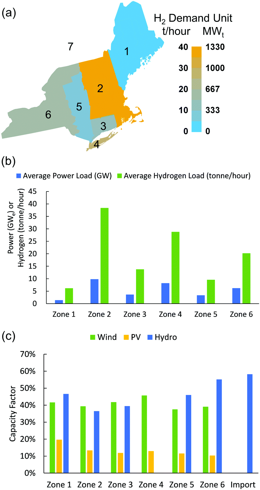 | ||
| Fig. 2 Demand and renewable energy resources distributions in the U.S. Northeast. H2 demands are estimated based on transportation fuel consumption data in 2017, and electricity demands are projections for 2050 as per the reference electrification scenario from NREL electrification futures study.35 (a) Geographical zone classification for U.S. North-East and average H2 demands for each zone; (b) average power and H2 demands for each zone; (c) Average capacity factors of wind, PV, and hydro for each zone. | ||
Electricity demand data (excluding electrolysis) are based on 2018 NREL electrification futures study load projection for 2050,35 with assumed business-as-usual technology advancement and reference electrification.
The H2 demands for each zone are developed based on available fuel consumption data, hourly refueling profiles36 for both light- and heavy-duty fuel cell electric vehicles (FCEV), and the relative penetration of FCEV. In the base case, we assume 1 million tonne per year H2 demand for the transport sector in the U.S. Northeast (corresponding to 20% FCEV penetration). Light-duty vehicle (LDV) fuel consumption for each zone is estimated using state-level gasoline consumption data for 2017 from the U.S. Energy Information Administration, which is then converted to a H2 consumption equivalent based on the relative efficiency of FCEV to gasoline internal combustion vehicle. Heavy-duty vehicle (HDV) demand projections are based on the National Freight Analysis Framework.37 The zonal average demands of power and H2 are shown in Fig. 2(b). Although the estimated H2 demands are based on its use in transportation, the model outcomes are also relevant for similar levels of H2 consumption in other end-uses.
For the power system, we include thermal, renewable, nuclear generation, and storage resources, whose main parameters are derived from the NREL annual technology baselines38 and the EIA Annual Energy Outlook 201839 for the year 2045, as summarized in Table 1. As no new coal plants will likely be built in this region, we consider the options of natural gas combined cycle gas turbine (CCGT), open cycle gas turbine, as well as CCGT with CCS. The VRE resource cost and availability in each zone are represented by supply curves40 to characterize different possible sites with specific resource availability profile, maximum potential capacity, and average cost of interconnection. We use three supply curves per zone for onshore wind and one supply curve per zone for PV. Offshore wind is included with no capacity limits and single resource profile for zone 2 and zone 4 based on sampling sites from the NREL Wind Toolkit that overlaps with the areas. Distributed PV is modelled with a separate resource profile per zone and minimum build requirement to meet 2029 projections by NYISO and ISONE. For hydropower, we consider hydro reservoir, hydro run-of-river, and Canadian hydro, whose hourly generation profiles are extrapolated from historical monthly outputs. The average capacity factors of VRE resources are shown in Fig. 2(c). Lithium-ion battery storage and pumped hydro storage are considered for electrical energy storage. The initial power transfer capacities between each zone are developed from the integrated planning model (IPM) documentation34 and are tabulated in Table S2 in the ESI,† while transmission expansion costs are listed in Table S1 (ESI†). Power transmission loss is accounted for as a fixed percentage (see Table S2, ESI†) of transmitted electricity for each line. The upstream social costs related to mining, equipment manufacturing, and transport are not considered in the case study results.
| Technology | Onshore Wind | Offshore Wind | Utility PV | Distributed PV | Li-ion Battery | Pumped Hydro | CCGT | OCGT | CCGT w/CCS | Nuclear |
|---|---|---|---|---|---|---|---|---|---|---|
| Power CAPEX (103$ per MW) | 1074 | 2179 | 725 | 882 | 119 | 1966 | 936 | 854 | 2080 | 6048 |
| Energy CAPEX (103$ per MW per h) | — | — | — | — | 136 | — | — | — | — | — |
| FOM (103$ per MW per year) | 35 | 59 | 8 | 6 | 2 | 44 | 13 | 11 | 27 | 119 |
| VOM ($ per MW per h) | — | — | — | — | 3 | — | 2 | 4 | 6 | 2 |
| Heat Rate (MMBTU per MW per h) | — | — | — | — | — | — | 6 | 10 | 8 | 10 |
| Round-trip efficiency | — | — | — | — | 85% | 80% | — | — | — | — |
| Lifetime (years) | 30 | 30 | 30 | 30 | 15 | 50 | 30 | 30 | 30 | 30 |
The main cost and performance parameters of H2 generation and G2P technologies are summarized in Table 2, which include electrolysis, natural gas fueled SMR with and without CCS (90% capture), stationary fuel cell, and H2 fueled CCGT. Similar to other studies5,7,18 focused on electrolyzer-grid interactions, we approximate electrolyzer lifetime as a fixed parameter (10 years shown in Table 2) rather than as a model variable that depends on electrolyzer operation. This approach does not account for the impact of use-dependent degradation of electrolyzer systems. We model trucks and pipelines as the key modes of H2 transmission, with the distance traveled in each case measured by the distances between the polygon centroids of each zone. At the same time, we also model them as potential storage resources, in tandem with stationary H2 storage. We model the potential deployment of two types of trucks, based on handling H2 as a cryogenic liquid or compressed gas, while the pipelines are considered as multiples of a 42 cm-diameter 100-bar pipeline being built across different geographies. We do not consider geological H2 storage as its availability in the U.S. Northeast region is uncertain.41 The parameters of H2 transmission and storage technologies are summarized in Table 3. The interfaces of each of these transmission and storage technologies with H2 generation and demand require compression and/or liquefaction depending on the state of H2. The compression/liquefaction costs comprise of the capital cost of the equipment as well as the operational costs from electricity consumption, which are also provided in Table 3.
| Pipeline | Gas tank | Liquid truck | Gas truck | |
|---|---|---|---|---|
| Unit capacity | 38.8 tonne per hour42 | 0.3 tonne44 | 4 tonne44 | 0.3 tonne44 |
| Capital cost | 3.72 M$ per mile42,45 | 0.58 M$ per tonne44 | 0.2 M$ per tonne44 | 1 M$ per tonne44 |
| Compression CAPEX (A) ($ per mile-unit) | 70046,47 | 0 | 0 | 0 |
| Compression CAPEX (B) (M$ per unit) | 0.75 | 0 | 0 | 0 |
| Compression electricity (A) (MWh per tonne-mile) | 0.014 | 0 | 0 | 0 |
| Compression electricity (B) (MWper h per tonne) | 1 | 0 | 0 | 0 |
| Unit OPEX ($ per mile) | 0 | 0 | 1.5 | 1.5 |
| Compression CAPEX (C) ($ per (tonne per hour)) | 0 | 0.544 | 3244 | 1.544 |
| Compression electricity (C) (MW per h per tonne) | 0 | 246,47 | 1146,47 | 146,47 |
| Boiloff rate | 0 | 0 | 3% | 0 |
| Lifetime (years) | 40 | 12 | 12 | 12 |
2.3 Modeling approximations
To maintain computational tractability with the expanded scope of investment and operational decisions considered here, we implement the following approximations, whose potential impacts on model outcomes are described below. Similar to other power sector CEM studies,9,40 we approximate annual hourly system operations based on modeling operations of the system over 30 representative weeks. The representative week selection is based on a K-means clustering technique, described in Mallapragada et al. (2020),31 in conjunction with heuristics regarding so-called “extreme” weeks applied to 7 years (2007–2013) of load and VRE availability data. Because representative periods identified via clustering techniques are known to emphasize typical weeks over extreme weeks, we apriori identified “extreme” weeks in the data set with the highest load and lowest average VRE capacity factors and added them to the set of 30 representative weeks to be considered by the model. We found that the model outcomes do not change significantly with more than 30 representative weeks (see Fig. S3, ESI†).Some of the technologies considered in the power and H2 supply chain, namely thermal power plants, H2 pipelines and SMR based H2 production facilities, exhibit economies of scale and limited operational flexibility, which typically requires using binary or integer variables to represent their investment and operations. However, because in nearly all scenarios, we are deploying more than one unit of each technology, the approximation of modeling investment in these technologies as continuous rather integer variables is relatively small. Prior modeling work48,49 has shown that such an approximation in practice results in a relatively small error in the overall dispatch and objective function while leading to large reductions in computational run times. In the case of SMRs, which represent centralized H2 production sources, we estimated that the additional H2 storage cost (pressurized gas tank) needed to make SMR output flexible only accounts for approximately 1% of the capital cost of SMR with CCS.§ Therefore, we assume SMR is as flexible as electrolysis in this study.
3 Results
3.1 Optimal technology mixes
Fig. 3 presents the optimal technology mixes with different CO2 prices and electrolyzer capital costs. The scenarios with 0, $50 per tonne, $100 per tonne, and $1000 per tonne CO2 prices correspond to approximately 100%, 40%, 30%, and 3% CO2 emissions compared to no CO2 price scenario, representing no carbon policy, moderate carbon policy ($50 or $100 per tonne), and deep decarbonization scenarios ($1000 per tonne), respectively. Here we highlight several observations from Fig. 3: first, from Fig. 3(a) and (b), we find that as the CO2 price increases, the H2 generation switches from central SMR, to SMR with CCS, and then to electrolyzer, accompanied by the power generation shifting away from CCGT to wind and solar. Second, electrolyzer is only cost-effective for deployment at higher CO2 prices and/or reduced capital costs compared to 2020 costs levels for multi-MW systems, which is near $800 to $1000 per kW.42 Third, although CO2 price increase favors an increasing share of H2 generation from electrolyzer and VRE power generation, it has a relatively small impact on the installed capacities of natural-gas-fueled H2 and power generation (SMR and CCGT). CCGT, mostly without CCS, and SMR with CCS remain cost-effective sources of flexible power and H2 supply for time periods when the lack of VRE generation result in scarcity pricing in the power system, for all CO2 price scenarios analyzed here (see Fig. 3(c) and (d)). Fourth, Fig. 3(c) and (d) highlight that CCS is utilized at lower CO2 prices in the H2 sector (less than $50 per tonne) than in the power sector (greater than $100 per tonne). This finding is a result of lower cost of CO2 capture at SMR facilities than CCGT power plants¶ as well as the higher utilization factor of SMR-CCS facilities vs. CCGT-CCS facilities in the analyzed scenarios. For example, in the scenario with $300 per kW electrolysis and $100 per tonne CO2 price, the capacity factor is 18% for CCGT, while 53% for SMR with CCS. Lastly, we find from Fig. 3(e) that H2 storage, both stationary and mobile, accounts for the majority of storage resources in no and moderate carbon policy scenarios, while the requirement for electrical storage increases with higher VRE penetration in the power sector. Overall, in the future energy system in the U.S. Northeast, we find that natural gas could play a key role as a flexible resource, and electrolytic H2 supply will be cost-effective with moderate carbon policy ($50 per tonne or greater) and/or electrolyzer capital cost reduction ($300 per kW or lower).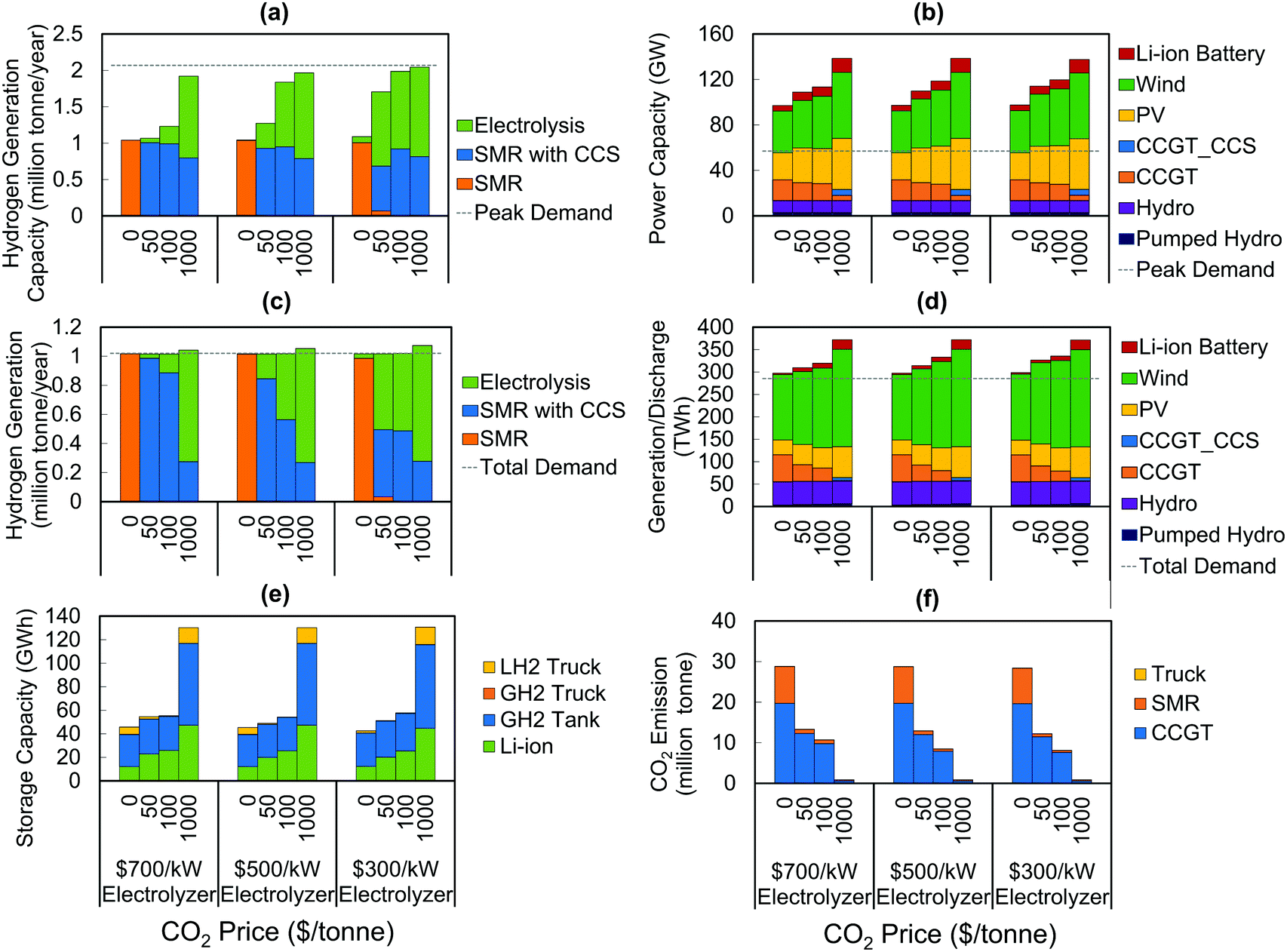 | ||
| Fig. 3 Optimal generation and storage capacity mixes and CO2 emissions in the power and H2 sectors under various CO2 price and electrolysis cost scenarios in U.S. Northeast. Technologies that are not cost-competitive are not shown. (a) H2 generation capacity; (b) power generation capacity; (c) H2 generation per year; (d) electricity generation or electrical storage energy discharge per year; (e) chemical/electrochemical energy storage capacity in power and H2 sectors; (f) CO2 emissions in power and H2 sectors. The hydrogen demand is 1 million tonne per year. The carbon price varies from 0 to 1000 $ per tonne (upper x label). The electrolyzer cost varies from $700 per kW to $300 per kW (lower x label). SMR: steam methane reformer; LH2: Liquid H2; GH2: Gaseous H2. | ||
For the baseline assumptions of H2 transport technologies (Table 3), we find that pipelines dominate trucks as the preferred mode of H2 transport. Fig. S4 (ESI†) highlights the magnitude of H2 transported broken down by mode, which suggests that the magnitude of H2 transported across the network under various scenarios is quarter or less than the total H2 demand (corresponding to 1 million tonne per year for results shown in Fig. S4, ESI†). This suggests that majority of the H2 demand is met by local production for our case study. In case there are further restrictions on deploying H2 production in some zones (similar to our baseline assumption of not allowing SMR in zone 4), it may be reasonable to expect greater role for H2 transportation in the overall supply chain. Fig. S4 (ESI†) also highlights that if pipeline costs are higher than our baseline assumption, e.g., due to geographical conditions or population density, then trucks tend to be more cost-effective. Our results also point to the inter-dependencies between technology choices for H2 production and transport. Specifically, we find that more H2 transportation is needed in the cases with SMR as the dominant H2 supply source compared to the cases with dominant electrolytic H2 supply (see Fig. S4, ESI†). Pipelines, because of their relatively high capital costs, are more cost-effective with large and steady H2 transmission demand from centralized SMR production, while electrolyzers can be deployed in a more distributed manner and thus complement smaller-scale and more flexible H2 transmission mechanisms like trucks.
3.2 Sector-coupling effects
When the power and H2 sectors are tightly coupled through electrolysis or H2-based power generation, the operational flexibility resources in the H2 sector can support VRE integration in the power sector, leading to overall system cost reductions. Fig. 4 demonstrates how the two sectors coordinate with each other in a representative week for the scenario with $300 per kW electrolyzer and $100 per tonne CO2 price. As shown in Fig. 4, electrolyzers are the main H2 supply source when VRE supply is abundant, such as hour 0 to 50. WhenVRE is in short supply relative to baseline electricity demand, such as between hour 60 to 80, SMR, stationary gas storage, and pipelines are utilized to meet H2 demands.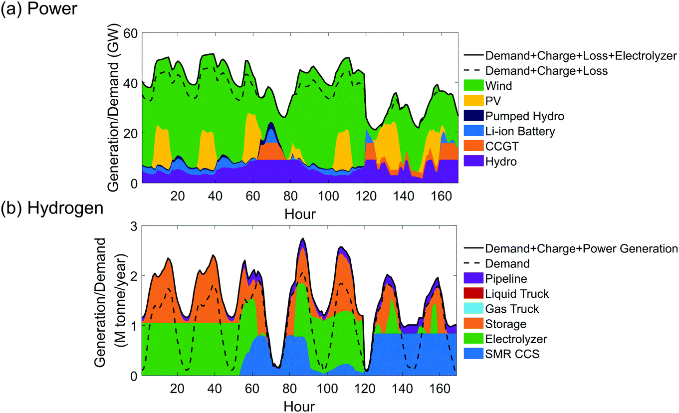 | ||
| Fig. 4 Generation and demand profiles in the power and H2 sectors in a representative week in the base case demand scenario (H2 demand 1 million tonne per year), $100 per tonne CO2 price and $300 per kWe electrolyzer capital cost. (a) Generation and demand profiles in the power sector; (b) Generation and demand profiles in the H2 sector. | ||
What are the benefits of coupling power and H2 supply chains? To quantify the impact of sector coupling, we compare the optimal power sector generation mixes with and without the options of conversion between power and H2 (electrolysis and H2-based power generation). In the latter case, H2 production would exclusively rely on natural gas based pathways.|| From Fig. 5(a), we can observe that the power and H2 interactions (mainly through electrolysis) boost VRE generation (as well as VRE capacities, see Fig. S5(a), ESI†) in the power sector, reduce VRE curtailment (see Fig. S5(b), ESI†) and reduce the need for dispatchable resources like CCGT and battery storage. This boosting effect grows as the share of electrolyzer in the H2 supply chain increases, due to either increasing CO2 price and/or increasing H2 demand. In the deep decarbonization scenarios with total H2 demands equal to 1 and 4 million tonne per year, the total VRE generation increases by 13% and 56%, and the VRE curtailment reduces by 4–6% (wind plus PV, see Fig. S5(b), ESI†), respectively.
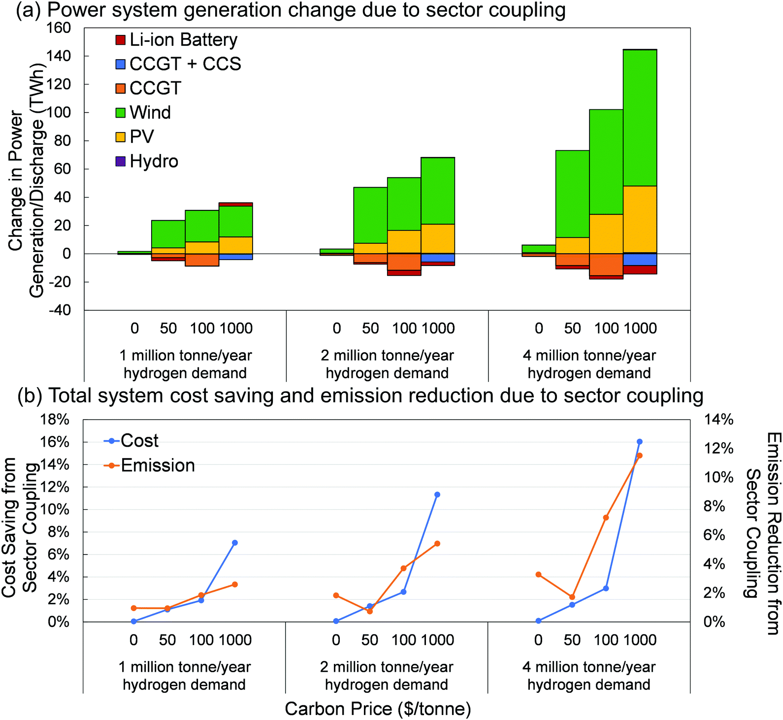 | ||
| Fig. 5 Differences in the optimal power system generation mix, total system cost, and CO2 emission between energy systems with and without conversions between power to H2 under various CO2 price and hydrogen demand scenarios. (a) Differences in the optimal power system generation mix; (b) Differences in the total system cost and CO2 emissions. The results are based on capital cost of electrolyzer of $300 per kWe. In (b), the cost savings are shown as percentages of the total system costs in each CO2 price and hydrogen demand scenario, while the emission reductions are shown as percentages of the CO2 emission in the case with $0 per tonne CO2, $300 per kW electrolyzer, and 1 million tonne per year hydrogen demand. | ||
As a result of reduced need in dispatchable power resources and cheaper electrolytic H2 production, we see cost savings from sector coupling in Fig. 5(b), increasing with CO2 price and H2 demand, and approaching 16% of the total cost** of the two sectors in the decoupled model in the deep decarbonization scenario. Sector coupling also leads to greater CO2 emissions reduction (up to 12% lower than the emissions in the case with $0 per tonne CO2, $300 per kW electrolyzer, and 1 million tonne per year H2 demand) than the case without coupling, owing to the increased penetration of VRE generation in the power sector. Both the cost savings and CO2 emissions reductions from sector coupling increase with H2 demand (either from transportation or other end-uses such as heating and industrial sectors), more than doubling for the deep decarbonization scenario as H2 demand quadruples. The CO2 emission reductions due to sector-coupling are high in the cases with no carbon policy because of the large absolute emissions in that case. As the CO2 price increases from $50 per tonne to $1000 per tonne, the CO2 emission reduction benefits from sector coupling increase since individual decarbonization becomes more expensive within each supply chain. The cost saving from sector coupling increases as H2 demand increases and peaks at 20% for H2 demand of 12.5 million tonne per year in the deep decarbonization scenario (see Fig. S6, ESI†), which is about 150% of the total annual power load in terms of LHV.
We also evaluated the impact of model outcomes when factoring non-combustion GHG emissions from natural gas use (including methane emissions) for power and H2 production. For this analysis, we set the GHG emission intensity per MMBtu of gas use based on estimated share of non-combustion GHG emissions in the life cycle GHG emissions of natural gas based power generation (on a CO2 equivalent basis using 100 year global warming potential).50 The non-combustion GHG emission per MMBtu of natural gas use for power and H2 generation are assumed to be the same (0.016 tonne-CO2-equivalent/MMBtu). Fig. S7 (ESI†) highlights that incorporating non-combustion GHG emissions related to natural gas use does not change the main findings of our study regarding the value of sector-coupling on supporting VRE integration in the power sector and cost savings for decarbonization. The sector-coupling benefits in system cost saving and CO2 emission reduction are greater when including non-combustion GHG emissions from natural gas, both reaching approximately 40% in the deep decarbonization case (see Fig. S7, ESI†). The conclusion regarding the cost-effectiveness of CCS use for H2 production over power generation is also robust to the inclusion of non-combustion GHG emissions from natural gas use. SMR with CCS still plays a role as non-electricity source for H2 during periods with low VRE availability, while CCGT with CCS is not economical anymore in the deep decarbonization case. That said, the capacity factor of SMR with CCS significantly reduces in the deep decarbonization case (see Fig. S8(a) and (c), ESI†), owing to the additional emissions penalty incurred by accounting for non-combustion GHG emissions. In a separate experiment, we also evaluated the impact of assuming a higher cost of SMR with CCS that is consistent with present-day cost estimates,42 and observed that its impacts on model outcomes are similar to the impact of including non-combustion GHG emissions (see Fig. S9, ESI†) and it does not change our broader conclusions about the impact of sector-coupling.
3.3 Storage or flexible demand
G2P generators are not cost-competitive in the results discussed above, even in the deep decarbonization scenario, because of the relatively high capital cost and the additional efficiency losses incurred in supplying power rather than H2. While they may become economically feasible in the future with economics of scale, technology innovations, and/or efficient deployment strategies (like sharing power conversion systems with electrolyzers or renewable plants), the results imply that the sectoral power exchange between the H2 and power sectors could be highly imbalanced, as opposed to energy storage (charging and discharging typically of the same order of magnitude).We further evaluate the role of H2 supply chain and its interaction with the power sector for different values of electrolyzer and G2P generator capital costs in Fig. 6. The electricity and H2 interactions are quantified using two model outputs: (a) the sum of annual power for H2 production (P2H) and annual power generated from H2 (PfH) as a percent of total annual electricity demand (excluding P2H) and (b) the ratio of annual P2H to PfH. The red, orange, and light pink stars in Fig. 6 represent high, medium and low capital costs for P2G and G2P technologies, respectively. We produce these representative future cost scenarios based on potential cost savings from economies of scale, technology learning, and system designs that saves critical component costs like power electronics. We can see from Fig. 6(a) that in the $100 per tonne CO2 price case, along the cost-reduction pathway (i.e. a straight line connecting the three star markers), the power exchange between the H2 and the power sectors increase from 2% to 10% of the total electric load. For the deep decarbonization scenario ($1000 per tonne CO2), the power exchange can be as high as 15% of the total electric load in the low technology cost scenario. Notably, as opposed to most literature that study H2 as long-duration/seasonal storage, our results in Fig. 6(b) indicate that H2 will more likely serve as a flexible demand response resource rather than long-duration storage. This can be seen in Fig. 6(b), where annual P2H generally tend to be several orders of magnitude greater than PfH, for almost the full technology cost space studied here. This observation stems from the additional efficiency losses and capital costs of converting H2 back to power associated with H2-based electricity storage vs. its use as a flexible demand resource. The only exceptions when the amounts of P2H and PfH are of the same order of magnitude under moderate decarbonization scenarios ($50–100 per tonne CO2) are with G2P capital costs below $700 per kW and electrolyzer capital costs greater than $500 per kW (excluding the cases when the total power exchange is extremely low). That the minimum cost of G2P generator for the H2 supply chain to play a storage role is higher in the moderate decarbonization scenario compared to the deep decarbonization scenario implies that the need for electrolytic H2 increases with decarbonization at a faster rate than the need for PfH.
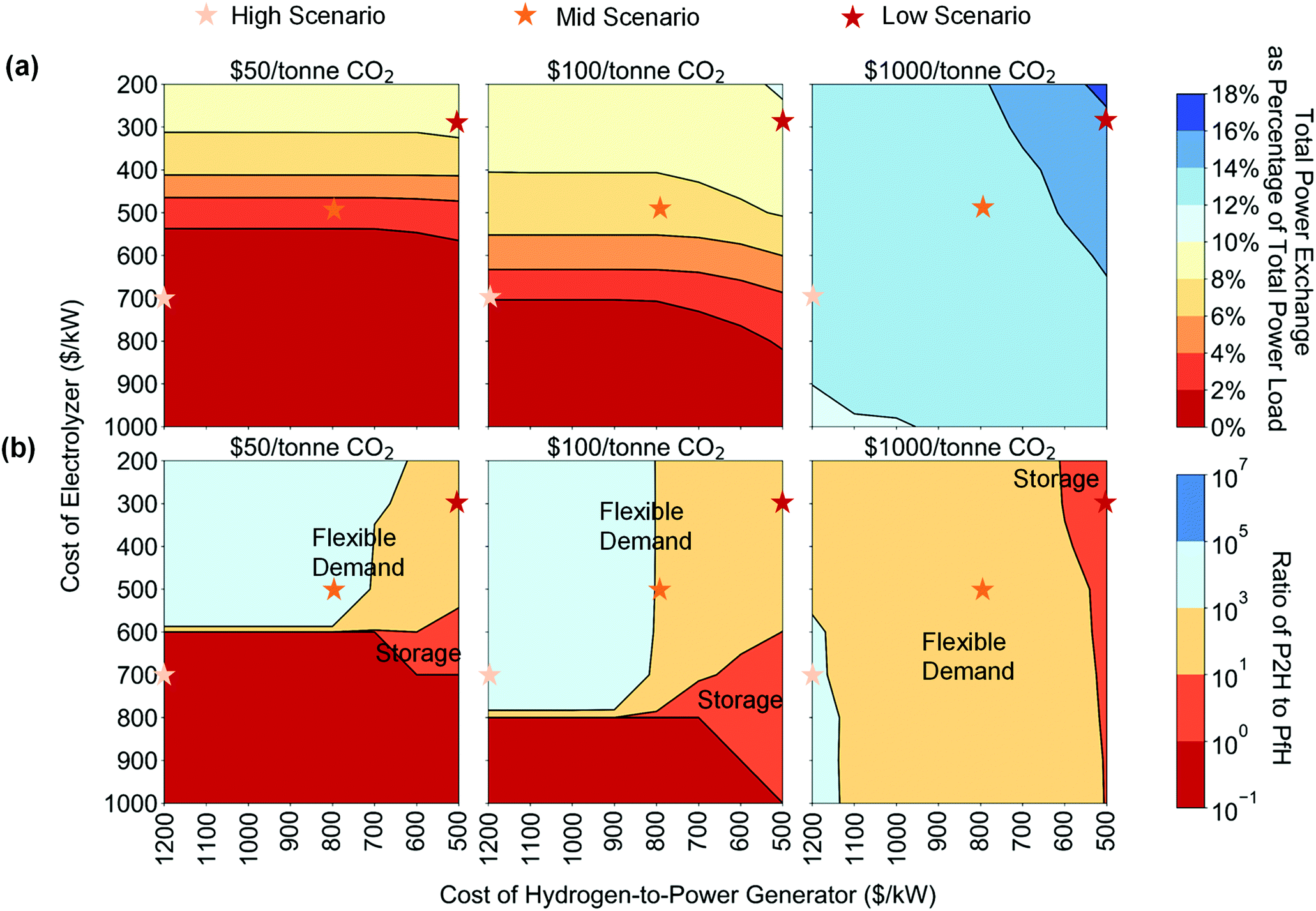 | ||
| Fig. 6 Power exchanges between H2 supply chain and power system under different costs of electrolyzer and G2P generator. (a) Total power exchange throughput, power used to generate H2 (P2H) plus power generated from H2 (PfH), as percentages to the total power load (without H2 generation); (b) the ratio of P2H to PfH. We define the role of H2 supply chain as storage when the P2H and PfH are of the same order of magnitude, as flexible demand when the P2H is of higher order of magnitude than PfH, and as generator when the P2H is of lower order of magnitude than PfH. The cost scenario of electrolyzer ranges from $1000 per kWe to $200 per kWe, and the cost scenario of H2-based power generator ranges from $1200 per kWe to $500 per kWe. The H2 demand scenario is set at 1 million tonne per year. All other parameters are the same as the base case. | ||
4 Conclusions
The interest in H2 for decarbonizing energy systems is unquestionably increasing, in part driven by declining technology costs, greater policy emphasis on decarbonizing non-electric end-uses, and recognition of the limitations of direct electrification in certain applications. The unique versatility of H2 as an energy carrier and its multiple uses, however, require a holistic view to accurately explore its role in future low-carbon energy systems and the accompanying technology pathways. Additionally, such a view could demonstrate the relative economic and environmental merits of H2 and electricity use for various end-uses as well as their complementarity as vectors for decarbonizing the energy system.To this end, we developed a generalized framework for cost-optimal energy infrastructure investment and operations for decarbonizing multiple end-use sectors based on coordinated use of electricity and H2 supply chains, which manages spatio-temporal variations in renewable energy inputs and energy demands. This modeling approach provides numerous insights on the technological make-ups of these energy supply chains, spanning production, transport, storage and end-use, and on their impacts on the cost of decarbonization, as highlighted via the U.S. Northeast case study.
First, in the coupled energy system, CCS is deployed at lower carbon prices in the H2 sector than the power sector, which can be interpreted as CCS being more competitive in the H2 supply chain than the power supply chain. This conclusion, however, goes counter to the observation that six times more CCS projects are expected to come online within this decade in the power sector than for H2 production.51 For regions like Europe, where decarbonization via H2 is part of many governments' decarbonization roadmap, our study highlights the importance of prioritizing CCS deployment for H2 production.
Second, power and H2 sector coupling via flexible electrolysis and H2 storage enables increased VRE penetration in the power sector, thereby reducing the need for alternative flexible resources for managing VRE variability (e.g. gas generation, battery storage, etc.), and in turn reducing total system cost. Moreover, as opposed to other power-sector focused studies that emphasize H2's value as a grid-scale storage resource,9–11 our multi-sector view highlights the greater system value of P2G as a flexible demand resource that avoids the additional efficiency losses and capital cost incurred with P2G2P pathways. This conclusion is found to be robust to future expectations on the capital costs of electrolyzer and G2P systems. Since electrolyzers and H2 storage are commercially available, this finding also suggests that H2 playing a role for grid balancing could be sooner than the full P2G2P routes becoming cost-effective.
Third, as compared to the independent optimization of each supply chain, we find that sector coupling via P2G, reduces the cost of energy system decarbonization, and that this benefit grows as the demand for H2 in other end-use sectors increases. Realizing the benefits of such cross-sector coordination, however, calls for policy and market reforms. For example, H2 prices need to be settled at similar spatio-temporal resolution as electricity prices, to provide incentives and signals for H2 infrastructure owners, and electrolyzers should be allowed to provide ancillary services to power systems. Taxation schemes harmonized for different energy carriers could help remove barriers for sector coupling.2 Moreover, both integrated operation and planning of power and H2 sectors, through a shared independent system operator or multiple system operator partnership (e.g., the cooperation of three gas and power system operators in Lower Saxony, Germany52), could help fully exploit the sector-coupling benefits.
There are a number of areas for future work that can build on this analysis. While this study has focused on H2 used in transportation, greater H2 demand might be realized from decarbonizing heating in buildings and industrial processes, such as ammonia production and steel manufacturing. Those H2 demands will have different temporal profiles and flexibility compared to FCEV charging, and thus may affect the H2 supply-demand balance in different ways. Accounting for these heterogeneous H2 demands should be further explored. Investigating the last-mile delivery of H2 is out of scope of this study but is definitely a key area for future work. The last-mile H2 distribution network will affect the total number of gas trucks needed for H2 transport in the system. Increased traffic congestion and safety considerations of very large H2 truck fleets could limit the deployment of trucks and increase the value of pipeline based transport. Further analysis in conjunction with traffic simulations is needed to assess this aspect. The proposed framework could also be expanded to study the cost-optimal trajectory of the energy transition. Prior work in the European context, has indicated that an early and steady transition is more cost-effective compared to a late and rapid transition.53
Regional factors, including resource availability and demand level, could significantly affect the optimal technology portfolios and the costs in both power and H2 sectors. For example, while natural gas supply is abundant in the studied U.S. Northeast region, it may be insufficient or expensive for many regions in the world, leading to higher shares of VRE, electrolytic H2 production, and storage. The ability to cost-effectively store H2 at various time scales and capacities is a critical factor in determining the optimal system architecture. Underground salt caverns, where available, can provide cheap H2 storage for VRE and electrolysis deployment. The competing role of CO2 storage with H2 storage in underground resources also need to be considered for relevant regions.
Conflicts of interest
There are no conflicts to declare.Acknowledgements
This work was partially supported by Shell Global Solutions International B. V., and the Low-Carbon Energy Centers on Electric Power Systems and Carbon Capture Sequestration and Utilization at MIT Energy Initiative. We would like to thank Mr Thaneer Malai Narayanan for his help, and Dr Joe Powell, Dr Mark Klokkenburg, and Prof. Robert Armstrong for their valuable advice on this work. We acknowledge the MIT SuperCloud and Lincoln Laboratory Supercomputing Center for providing resources that have contributed to the research results in this paper.References
- Nat. Energy, 2019, 4, 169 Search PubMed.
- Creating an interconnected decarbonized energy system benefiting industry, the power sector and society, DNV GL report, 2020.
- J. Ramsebner, R. Haas, A. Ajanovic and M. Wietschel, WIREs Energy and Environ., 2021, 10, e396 CrossRef.
- O. Schmidt, A. Gambhir, I. Staffell, A. Hawkes, J. Nelson and S. Few, Int. J. Hydrogen Energy, 2017, 42, 30470–30492 CrossRef CAS.
- O. J. Guerra, J. Eichman, J. Kurtz and B. M. Hodge, Joule, 2019, 3, 2425–2443 CrossRef.
- D. S. Mallapragada, E. Gençer, P. Insinger, D. W. Keith and F. M. OSullivan, Cell Rep. Phys. Sci., 2020, 1, 100174 CrossRef.
- C. E. Finke, H. F. Leandri, E. T. Karumb, D. Zheng, M. R. Hoffmann and N. A. Fromer, Energy Environ. Sci., 2021, 14, 1517–1529 RSC.
- G. Glenk and S. Reichelstein, Nat. Energy, 2019, 4, 216–222 CrossRef CAS.
- O. J. Guerra, J. Zhang, J. Eichman, P. Denholm, J. Kurtz and B.-M. Hodge, Energy Environ. Sci., 2020, 13, 1909–1922 RSC.
- A. Clerjon and F. Perdu, Energy Environ. Sci., 2019, 12, 693–705 RSC.
- M. A. Pellow, C. J. M. Emmott, C. J. Barnhart and S. M. Benson, Energy Environ. Sci., 2015, 8, 1938–1952 RSC.
- J. A. Dowling, K. Z. Rinaldi, T. H. Ruggles, S. J. Davis, M. Yuan, F. Tong, N. S. Lewis and K. Caldeira, Joule, 2020, 4, 1907–1928 CrossRef.
- A. Zerrahn and W.-P. Schill, Renewable Sustainable Energy Rev., 2017, 79, 1518–1534 CrossRef.
- M. McPherson, N. Johnson and M. Strubegger, Appl. Energy, 2018, 216, 649–661 CrossRef CAS.
- H. Khani and H. E. Z. Farag, IEEE Trans. Sustain. Energy, 2018, 9, 940–951 Search PubMed.
- H. Yang, Q. Li, S. Zhao, W. Chen and H. Liu, IEEE Access, 2019, 7, 89330–89341 Search PubMed.
- S. J. Davis, N. S. Lewis, M. Shaner, S. Aggarwal, D. Arent, I. L. Azevedo, S. M. Benson, T. Bradley, J. Brouwer, Y. M. Chiang, C. T. M. Clack, A. Cohen, S. Doig, J. Edmonds, P. Fennell, C. B. Field, B. Hannegan, B. M. Hodge, M. I. Hoffert, E. Ingersoll, P. Jaramillo, K. S. Lackner, K. J. Mach, M. Mastrandrea, J. Ogden, P. F. Peterson, D. L. Sanchez, D. Sperling, J. Stagner, J. E. Trancik, C. J. Yang and K. Caldeira, Science, 2018, 360, 6396 CrossRef PubMed.
- N. Sunny, N. Mac Dowell and N. Shah, Energy Environ. Sci., 2020, 13, 4204–4224 RSC.
- M. Victoria, K. Zhu, T. Brown, G. B. Andresen and M. Greiner, Energy Convers. Manage., 2019, 201, 111977 CrossRef.
- E. F. Bødal, D. Mallapragada, A. Botterud and M. KorpÅs, Int. J. Hydrogen Energy, 2020, 45, 32899–32915 CrossRef.
- T. Brown, D. Schlachtberger, A. Kies, S. Schramm and M. Greiner, Energy, 2018, 160, 720–739 CrossRef.
- J. Li, J. Lin, H. Zhang, Y. Song, G. Chen, L. Ding and D. Liang, IEEE Trans. Sustain. Energy, 2020, 11, 1773–1784 Search PubMed.
- M. Reuß, T. Grube, M. Robinius, P. Preuster, P. Wasserscheid and D. Stolten, Appl. Energy, 2017, 200, 290–302 CrossRef.
- L. Welder, D. S. Ryberg, L. Kotzur, T. Grube, M. Robinius and D. Stolten, Energy, 2018, 158, 1130–1149 CrossRef.
- A. O. Bique and E. Zondervan, Chem. Eng. Res. Des., 2018, 134, 90–103 CrossRef.
- S. De-León Almaraz, C. Azzaro-Pantel, L. Montastruc and S. Domenech, Int. J. Hydrogen Energy, 2014, 39, 11831–11845 CrossRef.
- L. Li, H. Manier and M. A. Manier, Comput. Chem. Eng., 2020, 134, 106683 CrossRef CAS.
- G. He, D. S. Mallapragada, A. Bose, C. F. Heuberger and E. Gençer, IEEE Trans. Sustain. Energy, 2021, 12, 1730–1740 Search PubMed.
- M. Z. Jacobson, M. A. Delucchi, M. A. Cameron, S. J. Coughlin, C. A. Hay, I. P. Manogaran, Y. Shu and A.-K. von Krauland, One Earth, 2019, 1, 449–463 CrossRef.
- M. Fasihi and C. Breyer, J. Cleaner Prod., 2020, 243, 11846 CrossRef.
- D. S. Mallapragada, N. A. Sepulveda and J. D. Jenkins, Appl. Energy, 2020, 275, 115390 CrossRef.
- J. D. Jenkins and N. A. Sepulveda, Enhanced decision support for a changing electricity landscape: the GenX configurable electricity resource capacity expansion model, MIT Energy Initiative technical report, 2017.
- G. He, DOLPHYN v0.2, 2021 DOI:10.5281/zenodo.5195017.
- Integrated Planning Model Documentation v6, EPA technical report, 2020.
- T. T. Mai, P. Jadun, J. S. Logan, C. A. McMillan, M. Muratori, D. C. Steinberg, L. J. Vimmerstedt, B. Haley, R. Jones and B. Nelson, Electrification futures study: Scenarios of electric technology adoption and power consumption for the united states, National Renewable Energy Laboratory, Golden, CO, Technical Report NREL/TP-6A20-71500, 2018.
- H2A Hydrogen Delivery Infrastructure Analysis Models and Conventional Pathway Options Analysis Results, Nexant, Inc. technical report, 2008.
- Freight Analysis Framework Version 4, Oak Ridge National Laboratory technical report, 2019.
- National Renewable Energy Laboratory, 2021 Annual Technology Baseline (ATB), 2021, https://atb.nrel.gov/.
- U.S. Energy Information Administration, Annual Energy Outlook 2018, With Projections to 2050, 2018.
- P. R. Brown and A. Botterud, Joule, 2021, 5, 115–134 CrossRef.
- A. S. Lord, P. H. Kobos, G. T. Klise and D. J. Borns, A Life Cycle Cost Analysis Framework for Geologic Storage of Hydrogen: A Scenario Analysis, Sandia National Laboratories technical report, 2010.
- The Future of Hydrogen, IEA technical report, 2019.
- Manufacturing Cost Analysis of 100 and 250 kW Fuel Cell Systemsfor Primary Power and Combined Heat and Power Applications, Battelle Memorial Institute technical report, 2016.
- C. Yang and J. Ogden, Int. J. Hydrogen Energy, 2007, 32, 268–286 CrossRef CAS.
- North American Midstream Infrastructure Through 2035 - A Secure Energy Future Report, The INGAA Foundation, Inc. technical report, 2014.
- S. Schoenung, Economic Analysis of Large-Scale Hydrogen Storage for Renewable Utility Applications, Sandia National Laboratories report, 2011.
- S. Samsatli and N. J. Samsatli, Appl. Energy, 2018, 220, 893–920 CrossRef.
- B. S. Palmintier, PhD thesis, Massachusetts Institute of Technology, 2013.
- B. S. Palmintier and M. D. Webster, IEEE Trans. Power Appar. Syst., 2014, 29, 1089–1098 Search PubMed.
- G. A. Heath, P. O'Donoughue, D. J. Arent and M. Bazilian, Proc. Natl. Acad. Sci. U. S. A., 2014, 111, E3167–76 CrossRef CAS PubMed.
- The Global Status of CCS Report, Global CCS Institute report, 2020.
- Gasunie, TenneT and Thyssengas reveal detailed, green ‘sector coupling plans’ using power-to-gas technology, 2018, https://www.tennet.eu/news/detail/gasunie-tennet-and-thyssengas-reveal-detailed-green-sector-coupling-plans-using-power-to-gas-tec/.
- M. Victoria, K. Zhu, T. Brown, G. B. Andresen and M. Greiner, Nat. Commun., 2020, 11, 6223 CrossRef CAS PubMed.
Footnotes |
| † Electronic supplementary information (ESI) available. See DOI: 10.1039/d1ee00627d |
| ‡ The last-mile distribution networks of electricity and H2 are not considered in this study. |
| § Assuming that a one-hour gas storage is installed to buffer SMR starting up or shutting down, then the capital cost of storage for SMR of one tonne per hour is $0.58 million, which is 1% of the capital cost of SMR with CCS ($391 million for a 9.2 tonne per hour unit). The electricity operating cost is negligible when SMR is ramping down (charging and compressing), as the electricity must be very cheap at the time. |
| ¶ The levelized CO2 abatement cost of CO2 capture facility is approximately $40 per tonne at SMR and $110 per tonne at CCGT, given the cost and efficiency assumptions in the study (CO2 transportation cost is assumed to be $20 per tonne-CO2). |
| || Electricity consumption by conditioning (compression and liquefaction) is still supplied by the power sector, and its cost is accounted in the same way as the coupled case with conversion between power and H2. |
| ** The levelized costs of electricity and H2 reduce by the same rate, if the cost savings are proportionally allocated between the power and H2 sectors. |
| This journal is © The Royal Society of Chemistry 2021 |