 Open Access Article
Creative Commons Attribution 3.0 Unported Licence
In situ polymerization process: an essential design tool for lithium polymer batteries†
Vidyanand
Vijayakumar
 abc,
Bihag
Anothumakkool
 ad,
Sreekumar
Kurungot
 c,
Martin
Winter
*aef and
Jijeesh Ravi
Nair
 *a
*a
aHelmholtz Institute Münster, IEK-12, Forschungszentrum Jülich GmbH, Corrensstraße 46, 48149 Münster, Germany. E-mail: m.winter@fz-juelich.de; j.nair@fz-juelich.de
bAcademy of Scientific and Innovative Research (AcSIR), Sector 19, Kamla Nehru Nagar, Ghaziabad, Uttar Pradesh 201002, India
cPhysical and Materials Chemistry Division, CSIR-National Chemical Laboratory, Pune, 411008, India
dTNO-Holst Centre, Dutch National Institute for Applied Scientific Research, High Tech Campus 31, 5656 AE Eindhoven, The Netherlands
eMEET Battery Research Center, Corrensstraße 46, 48149, Münster, Germany
fInstitute of Physical Chemistry, University of Münster, Corrensstraße 28/30, 48149, Münster, Germany. E-mail: Martin.Winter@uni-muenster.de
First published on 11th February 2021
Abstract
Polymer electrolytes (PEs), a type of solid-state electrolytes (SSEs), have been in contention for nearly half a century to replace organic liquid electrolytes (LEs) that are used in state-of-the-art lithium-ion batteries (LIBs). They are envisaged to accelerate the industrial-scale production of safe, energy-dense, flexible, and thin lithium polymer batteries (LPBs). LPBs are expected to be widely employed for electric propulsion and other futuristic applications, such as flexible electronics and the Internet of Things (IoT). Even though several polymer architectures and chemistries have been attempted so far, PEs that can outperform LEs remain a real challenge. Apart from inadequate Li+-ion transport properties, challenges concerning the integration of PEs and the engineering of compatible, robust, and durable interfaces and interphases at both the electrodes of LPBs must be appropriately addressed. Recently, the in situ polymerization process has been widely employed as a robust fabrication tool for surpassing the intricacies related to the integration of PEs in LPBs. Hence, in this review, we focus on the in situ polymerization processes that employ various polymerization methods (e.g., free-radical polymerization, ionic polymerization, electropolymerization, condensation polymerization, etc.), functional monomers and oligomers (e.g., acrylate, methacrylate, allyl and vinyl ethers, epoxides, etc.), and PE integration strategies for the fabrication of lithium (ion and metal) polymer batteries (LIPBs and LMPBs). Additionally, this review also evaluates the approaches that have been developed until now to implement the in situ processing of LPBs from large-sized pouch cells to flexible-/printable-batteries and even microbatteries.
Broader contextElectrochemistry and polymer chemistry are two independent fields of science that have grown significantly over the last two centuries. Indeed, energy storage devices, in particular rechargeable lithium polymer batteries (LPBs), demand these two strong fields of science to be indispensable and mutually constructive to one another. An affordable polymer electrolyte (PE) with a suitable solvent-free fabrication method would revolutionize the secondary energy storage sector by bringing in thin architecture, low cost, high energy density, eco-friendliness, safety, and durability. Even if the raw material availability is expanded and a competitive synthesis procedure is established, transcending lithium ion batteries (LIBs) by superior LPBs is only possible through adaptive, integrated, economic, sustainable, and upscalable processing techniques. Indeed, in situ polymerization processes will empower the engineering of competent PEs and conformal interfaces and interphases in solid-state energy storage and conversion devices. In this review, we emphasize state-of-the-art LPB fabrication techniques (in situ and ex situ processes), the history of polymer-based rechargeable batteries (literature from the 1830s to the 2020s), numerous classes of monomers and oligomers, and various other innovative and modern PE processing approaches. In addition to conventional LPBs, the prospects of various in situ and ex situ approaches that are embraced for flexible and printable batteries (screen-printing, 3D-printing, etc.) and microbatteries are also envisaged. |
1. Introduction
Among the rechargeable battery technologies available today, lithium-ion batteries (LIBs) are unanimously considered as the most capable electrochemical energy storage (EES) technology due to their high gravimetric energy density of ≈260 W h kg−1 and possible energy density expansion above 500 W h kg−1.1–7 Since the commercialization in 1991 by SONY, LIBs have been extensively used in portable electronics. Indeed, LIBs are the frontrunner technology fueling the transition of the mode of transportation from non-renewable fossil fuel-based internal combustion engines (ICEs) to the prospects of electromobility.8,9 For example, a standard ICE burns an average of ≈5.5 L of gasoline for 100 km distance, and the same amount of fuel corresponds to ≈50 kW h of energy.10 From the equal amount of energy stored in an LIB, an electric vehicle (EV) travels ≈312 km, which means that, in practical terms for 100 km, an EV consumes only 16 kW h of energy.11 This indicates that an LIB with an electric motor is at least three times more efficient than a gasoline-powered ICE. Besides, the “lost” part of the energy (∼34 kW h) from gasoline results in unproductive work, mostly heat. Therefore, LIBs are envisaged to contribute immensely towards the flourishment of sustainable means of transportation in the form of EVs and lower environmental hazards. Moreover, the efforts to implement LIBs for smart/green grid (stationary) energy storage systems assure effective intermittent and reliable energy generation, transmission, and distribution, through intermediate storage, thus further improving the goals of a sustainable lifestyle. In 2019, considering the development of LIBs and its impeccable impact on modern society, John B Goodenough, M Stanley Whittingham, and Akira Yoshino were conferred with the Nobel Prize in Chemistry.12A typical LIB is composed of an anode (negative electrode), cathode (positive electrode), organic liquid electrolyte (LE), and separator, as demonstrated in Fig. 1a. Li+-ion intercalating compounds (e.g., graphite),13,14 alloying materials (e.g., Si and Sn),15,16 and (nanoscale) metal oxides (e.g., Li4Ti5O12, TiO2, and Fe2O3)17 are often employed as the anode. Lithiated layered transition metal oxides [e.g., LiNixMnyCozO2 (NMC), LiCoO2 (LCO), and LiNixCoyAlzO2 (NCA)] in several compositions, olivine-type metal phosphates [e.g., LiFePO4 (LFP) and LiMnPO4], spinel oxides [e.g., LiMn2O4 (LMO) and LiMnxNiyO4 (LNMO)], etc., are popular amongst the available cathodes.18,19 Linear (e.g., dimethyl carbonate, DMC) and cyclic (e.g., ethylene carbonate, EC) carbonates in numerous compositions are exploited as electrolyte solvents, which in conjunction with lithium salts of perchlorate (e.g., LiClO4), fluoroborate (e.g., LiBF4), fluorophosphate (e.g., LiPF6), sulfonylimide (e.g., LiFSI and LiTFSI), etc., form the typical organic LEs. 1 M LiPF6 in EC:DMC is a classic example of a widely used organic LE.20 Porous single- or multi-layer polyolefin sheets (e.g., Celgard™) or glass-fiber mats are often used as the separator.21,22 Further, LIB electrodes contain binders,23 conducting additives,24–26 and current-collectors.27,28 The main feature of a binder is its ability to hold together the electrode particles containing the active material and conductive additives such as carbon black (e.g., Super P® and Super C®). Also, binders enhance the adhesion of electrode components to the respective current-collectors (Cu for the anode and Al for the cathode).6 Indeed, poly(vinylidene difluoride) (PVdF) and its copolymer poly(vinylidene difluoride-co-hexafluoropropylene) (PVdF–HFP) are the most widely used binder materials.29
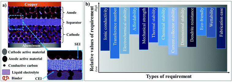 | ||
| Fig. 1 Schematic illustration of the components of the (a) state-of-the-art LIB cell and (b) fundamental requirements of an ideal electrolyte system. | ||
Organic LEs are an integral part of LIBs, playing the fundamental role of Li+-ion conduction between the electrodes.30–32 Additionally, the LEs facilitate the formation of stable surface protection layers, e.g., the solid electrolyte interphase (SEI)33 and cathode electrolyte interphase (CEI)34 on the respective electrode surfaces (see Fig. 1a), paving the way for reversible Li+-ion shuttle.31,35–40 The most relevant requisites for an ideal electrolyte are depicted in Fig. 1b, where every requirement is graded according to its relevance in delivering optimum performance in LIB cells. Nevertheless, LEs hold several inherent limitations, including the possibility of electrolyte leakage, a narrow range of operation temperature (5 to 45 °C), and a probable fire hazard during cell-failure through overcharging or dendrites [also called High Surface Area Lithium (HSAL) mediated cell short-circuit].41–44 Besides, from a technological perspective, the electrochemical stability issues associated with the LEs combined with high-voltage nickel-rich cathodes are a significant concern to be resolved from a technical standpoint.45 The recent developments in aqueous electrolytes made of a high concentration of lithium salt (also called ‘water-in-salt’) are envisaged to emulate the success of LIB technology of the 1990s.46,47 Furthermore, aqueous electrolytes can address the environmental and safety concerns about the use of inflammable organic solvents. However, the research is in the early stage and yet to flourish beyond the lab-scale.
Affording the future energy demands for high energy applications like long-range EVs and grid-storage, the energy density of state-of-the-art LIBs should be increased beyond a value of >500 W h kg−1. Theoretically, the energy density of an LIB cell can be increased by 57% by doubling the capacity of a positive electrode. However, achieving high capacity beyond existing state-of-the-art materials at the cathode level is a monumental task. Indeed, high-voltage cathodes with high capacity require compatible electrolytes with high oxidative stability. Interestingly, a ten-fold increment in the capacity of a negative electrode can also result in a large increase (∼47%) in energy density.48–50 Therefore, the replacement of graphite (theoretical capacity of 372 mA h g−1) by a Li-metal anode (theoretical capacity of 3860 mA h g−1)51 can elevate the energy density of the resulting battery with the existing cathode materials and chemistries. In this aspect, LIBs that use Li-metal as the anode are receiving popular attention and are called lithium metal batteries (LMBs).
The complications arising from the currently pursued organic carbonate-based LEs against the Li-metal anode owing to HSAL growth are a grave concern, which is preventing the commercialization of LE-based rechargeable LMBs (LE-LMBs).52–54 Even tailor-made LEs (highly concentrated solutions, fluorinated solvents, specialty additives that form a fluorine-rich SEI layer, etc.), which can control and modify the Li-metal surface by the formation of artificial SEIs, cannot fully avoid HSAL-related cell failure during long-term cycling. Such efforts require further optimizations and validations. In realistic conditions, where the LE amount is restricted below 3 g A h−1 and the areal capacity to be achieved is in the range of 2–5 mA h cm−2, HSAL related issues become severe.5 By a simple calculation, one can understand that 2.0 mA h cm−2 equivalent Li deposition corresponds to ∼10 μm thick layer of Li, whereas an equivalent of 5 mA h cm−2 leads to ∼25 μm thick layer at the Li-metal anode. Additionally, porosity or voids formed during the Li plating/stripping processes will increase many fold the actual volume of the Li-metal anode in an LE-LMB. Hence, the continuously evolving Li-metal surface, volume expansion arising from Li deposition, short circuits induced by HSAL formation, and thin separator layer complicate the adaptation of LE-LMBs to commercial applications. Besides, the in situ formation of artificial SEI layers to protect the Li-metal surface within the cell housing by using a lower amount (<3 g A h−1) of LE may induce excessive consumption and decomposition of solvents. Hence, the harmful side products formed, such as gases or even small organic molecules, may further catalyze the exothermic decomposition of the electrolyte components, resulting in increased cell impedance, short-circuits, and fire hazards. For example, HSAL growth induced failure of an LE-LMB cell during repeated charge–discharge cycling is schematically represented in Fig. 2, where a needle-like HSAL deposition piercing through the separator to induce a short-circuit is depicted.55
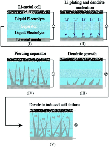 | ||
| Fig. 2 The HSAL (needle-like)-incited failure of an LE-LMB cell during repeated charge–discharge cycling. | ||
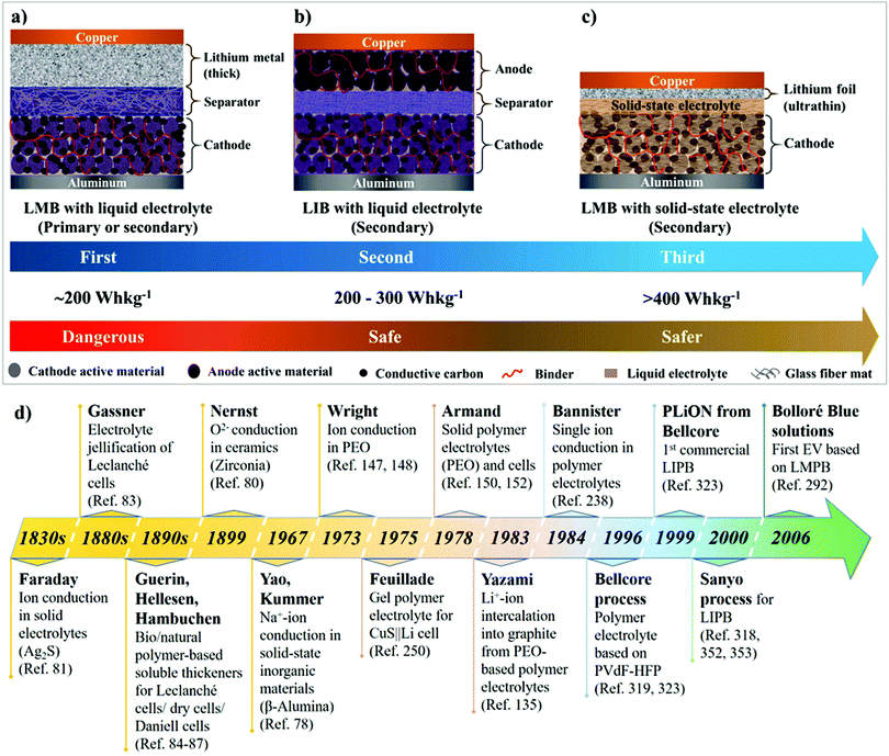
The ongoing intricacies associated with LEs have propelled the concept of solid-state electrolytes (SSEs) for LIBs and LMBs, resulting in the development of two major classes of solid-state systems, namely, polymer electrolytes (PEs) and inorganic solid-state electrolytes (ISEs). The primary objective of invoking SSEs for LIBs and LMBs is to address the safety concerns associated with organic LEs. Besides, the use of SSEs in place of LEs will facilitate the design of safer, flexible, durable, thinner, lightweight, leak-free, and easy to fabricate solid-state LMBs and LIBs. It is anticipated/hypothesized that Li+-ion conducting SSEs with shear modulus values higher than Li-metal (G′ > 3.4 GPa) can hinder HSAL growth during repeated charge–discharge steps in solid-state LMBs.56–61 Therefore, SSEs combined with thin Li-metal anodes (thickness <20 μm) can potentially fuel successful commercialization and widespread implementation of rechargeable solid-state LMBs. Fig. 3a–c depict the overall transformation of an earlier model of an Li-metal anode|LE-based primary LMB (pLMB) and LE-based rechargeable LMB (LE-LMB) (1st generation) to the state-of-the-art Li-metal-free anode (e.g., intercalation)|LE-based LIBs (2nd generation), and lastly to the most recent Li-metal anode|SSE-based rechargeable LMBs (3rd generation). In the context of this review, for simplicity, the term ‘lithium battery (LB)’ is used to represent all types of battery cells that make use of Li-based electrochemistry. When a PE is used as the SSE in the LMB configuration as shown in Fig. 3c, such solid-state LMBs are called lithium metal polymer batteries (LMPBs). Similarly, LIBs with a PE replacing the conventional LE are called lithium-ion polymer batteries (LIPBs). Besides, the term ‘lithium polymer battery (LPB)’ is used to generalize all PE-based LIBs and LMBs. The innate components such as SEI and CEI layers that are formed during the initial cycles of an LIB (Fig. 1a) apply to LPBs as well.
The synthesis and upscalability of PEs will be of paramount importance when LIPBs and LMPBs are considered for large scale production and commercialization. PEs for LPBs have been extensively reviewed in the past.62–68 Indeed, excellent reviews are available discussing the different types of PEs such as gel polymer electrolytes (GPEs), polymer composite electrolytes (PCEs), and solid polymer electrolytes (SPEs).69–71 Thorough overviews of the types of polymer hosts (such as PEO and PEO-free hosts) used in the preparation of PEs are also available.72–74 Besides, a few available reviews address the fundamental aspects of order and disorder, and ion transport models of PEs.75,76 These attempts mainly covered various types of PEs, their synthetic methods, and fundamental aspects in detail. However, reviews addressing the fabrication of LIPBs and LMPBs emphasizing the importance of processing methods, which significantly influence the electrode|electrolyte interfaces, interphases, and electrochemical performance, are scarce. Hence, understanding and segregating the bits and pieces of PE research from the LPB cell fabrication/processing point of view is vital, and, through this review, we are narrowing down this knowledge gap.
The primary objective of this review is to comprehensively discuss the reports on LIPB and LMPB cell fabrication methods focused on improving the electrode|electrolyte interface and interphase using the in situ polymerization process (explained in Section 4.2). A concise understanding of the enormous amount of scientific research activities carried out in the past four decades on the in situ processing of LBs can leverage their prospects of practical implementation and industrial-scale production. Hence, many of the available reports are comprehensively compiled, considering the type of in situ processing approach adopted and the polymer hosts used. The potential of the in situ process in futuristic microbatteries, and printable- (e.g., 3D-printed), and flexible-LPBs is also discussed at the end.
2. History of LBs: liquid electrolytes to polymer electrolytes
The significant milestones in the evolution of solid-state electrolytes for various EES devices through history are presented in Fig. 3d.77–80 Solidification of electrolytes for improving portability and preventing leakage of liquid components has been known since the 19th century. Michael Faraday, in the 1830s, discovered ionic conduction in solids for the first time.81,82 Carl Gassner, in the 1880s, improved Leclanché cells by introducing the concept of ‘electrolyte jellification’ using plaster of Paris as the solid-state host.83 Several other inventors later improvised the concept by employing jellified semi-solid electrolytes made of cellulosic materials (e.g., sawdust), bio/natural polymer-based soluble thickeners (e.g., starch, agar paste, etc.), simple cloth or starch-coated paper as the separator, etc., in various Leclanché cells/dry cells/Daniell cells.84–87 These reports dating back to the 19th century indicate the momentous importance of solidification/immobilization of the electrolyte in EES devices.During the 1950s, there have been observations regarding the formation of a passivation layer on the surface of highly reactive Li-metal when immersed in organic solvents.88–90 This surface passivation layer was later investigated in detail by Peled et al. and later named the SEI.91–95 This SEI layer could prevent the continuous oxidation of Li-metal in the organic LE. Further research paved the path towards the conceptualization and commercialization of 1st generation LMBs (Fig. 3a) during the period of 1960–1970s, which comprised a thick Li-metal foil as the anode, an organic LE, and a cathode amongst transition metal halides (e.g., CuCl2), oxides (e.g., MnO2 and MoS2), SOCl2, SO2, etc.77,96–100 However, the commercialized LMBs were LE-based pLMBs (Fig. 3a). When attempts were made to convert these pLMBs into rechargeable configurations, the morphological instability of Li-metal during the repeated charge–discharge cycling prevented the realization of safe, reliable, and rechargeable LE-LMBs. Nevertheless, these early models opened several new opportunities and challenges that led to modern-day rechargeable LIBs and LMBs.
Ever since the commercialization of pLMBs, enormous efforts were dedicated to transforming the model into a rechargeable one. The major part of the research was focused on tuning LEs and cathode materials, through which efficient 1st generation LE-LMBs (Fig. 3a) were expected to be realized (during the 1960s to 1980s).101–104 Several breakthrough discoveries leading to state-of-the-art electrode materials and electrolytes used in contemporary LIB cells were the result of continuous research focused on developing safe LE-LMBs. For instance, the introduction of intercalation cathodes by Whittingham et al.105,106 and the development of LiCoO2 (LCO) by Goodenough et al.107 were achieved during the period of the mid-1970s to the beginning of the 1980s (for details about the history of electrolytes, salts and cathode materials used in LBs, follow the referenced articles31,108–118). However, the inferior cycling life and unsafe operation of the then-designed LE-LMB models remained as the primary bottleneck, mainly due to the fire hazards and cell-failure arising from the HSAL growth at the anode side.104,119–122 In fact, several manufacturers (e.g., Moli Energy) recalled some of their commercialized LE-LMBs from the market due to fire hazards and malfunctioning of the associated devices, which ended the general curiosity on the same.96,123 However, it should be noted that, even today, many of the pLMBs developed during the 1970s and 1980s, such as MnO2|LE|Li and C|LiAlCl4 in SOCl2|Li, still have their market-share for niche applications.77
The quest towards developing safe anodes other than Li-metal led to the 2nd generation of LBs, currently known as LIBs, which were commercialized by SONY in 1991 (Fig. 1 and 3b). The state-of-the-art LIBs use a graphite-based intercalation anode. Unlike the reactive Li-metal, graphite can facilitate a stable SEI with the organic LE, hence preventing HSAL growth and cell-failure under normal service conditions. During the mid-1970s, Besenhard et al. proposed, for the first time, the concept of reversible electrochemical intercalation of alkali metal ions into graphite from organic LEs.124–126 Several reports followed this discovery and developed different types of carbon-based materials that are capable of reversible Li-intercalation.127–135 In 1977, Basu et al. put forward the preparation of stage 1 Li-intercalated graphite (LIG)136,137 with a high-temperature physical method that paved the path towards the development of LiC6 anode as an alternative to Li-metal at Bell Labs.138,139 Later, Rachid Yazami in 1983 demonstrated the simple but groundbreaking phenomenon of electrochemical intercalation of Li+-ions into a graphite host from a poly(ethylene oxide) (PEO)-based dry polymer electrolyte (DPE), for which he is often considered as the inventor of the graphite anode for LIBs.135,140,141 Ultimately, Akira Yoshino from Asahi Kasei Corporation is credited as the inventor of the modern-day LIB, as he engineered the first practical prototype that operates through a dual-intercalation mechanism in LEs followed by commercialization in 1991.142 Compared to 1st generation LMBs (pLMBs and LE-LMBs), LIBs are safe and long-lasting despite their lower energy density, which is compromised due to the replacement of Li-metal with a graphite analog.143,144 Conversely, the new developments in LIBs include alternative materials such as alloying (e.g., silicon and tin) and conversion anodes [e.g., transition metal oxides (TMOs)] as close competitors to graphite for enhancing the energy density.145,146 From a practical perspective, since commercialization in 1991, the configuration of state-of-the-art LIBs has not undergone major changes. Although several new materials (high-energy anodes and cathodes, better lithium salts, solvents, separators, etc.) have emerged, the basic configuration of LIBs remains the same. With the inception of SSEs (PEs and ISEs), the possibility of realizing safer, thinner, durable, and energy-dense solid-state LMBs possessing rechargeability has sprouted again (Fig. 3c, 3rd generation).
Ion conduction through polymer hosts has been known for nearly half a century.88 The first example was PEO-based alkali metal (Li or K) ion conducting PEs (historically called DPEs), which were first introduced by P. V. Wright et al. in the 1970s, and later this research field flourished and was independently recognized with the critical contributions from Armand et al.147–152 In the case of PEO, the polar heteroatoms (oxygen) of ethylene oxide (–EO–) chains facilitate the solubility of electrolyte salts, and the transport of these dissociated ions occurs through ion hopping and polymer chain segmental motion. Generally, the ion mobility induced by polymer chain segmental motion occurs above the glass transition temperature (Tg) of the constituent polymer host.153–155
Ideally, PEs are envisaged to be superior compared to ISEs (glass electrolytes, ceramic electrolytes, etc.) due to their low cost, ease of synthesis and processing, and excellent mechanical properties.82,156–158 Indeed, many available fast and single-ion conducting ISEs are known for their instability against Li-metal.71,159–161 Further, high grain boundary resistance and processability are the immediate challenges that impede the application of ISEs in solid-state LIBs and LMBs.162,163 Nonetheless, ISEs based on sulfides (e.g., Li7P3S11) are an exception as they display excellent ionic conductivity >1 mS cm−1 at RT164,165 and a low activation energy of 12 kJ mol−1 for Li+-ion transport.166 Unfortunately, the narrow electrochemical stability window of sulfide electrolytes is a drawback, which demands artificial SEIs or separate polymer layers in practical applications.165 Additionally, the sensitivity to air and moisture requires careful and precise processing conditions and stringent safety regulations (mainly due to sulfur). Moreover, the molar concentration (mol L−1) of lithium required in ISEs is at least one to several orders of magnitude higher than organic LEs or PEs (see Table 1).87 Thus, the overall research towards improving ISEs is in its early stages, and detailed overviews are available elsewhere.167,168 Ultimately, the flexibility, low cost, and ease of processability of PEs enable them to be one of the suitable choices for futuristic solid-state LPBs. It is also reported that the flexible nature of PEs has another advantage of tolerating the volume changes occurring in the electrodes and minimizing HSAL growth and related SEI layer rupture during the charge–discharge cycles.169–174 Indeed, such characteristics can reduce the risks/hazards related to short-circuits to an extent.
| Name | Formula | Li concentration, mol L−1 | Ionic conductivity, mS cm−1 |
|---|---|---|---|
| LE | |||
| LP30 | 1 M LiPF6 in EC:DMC (1![[thin space (1/6-em)]](https://www.rsc.org/images/entities/char_2009.gif) : :![[thin space (1/6-em)]](https://www.rsc.org/images/entities/char_2009.gif) 1) 1) |
1.0 | Ca. 11.2 (25 °C)175 |
| Solid polymer electrolyte | |||
| PEO | P(EO)20LiTFSI | 1.1 | Ca. 0.36 (60 °C)176 |
| Inorganic solid electrolytes | |||
| Oxide | |||
| LLTO | Li3.3La0.56TiO3 | 81.3 | Ca. 1–0.01 (27 °C)177 |
| LLZO | Li7La3Zr2O12 | 41.3 | Ca. 0.2 (25 °C)178,179 |
| LISICON-family | Li14ZnGe4O16 | 66.7 | Ca. 10−3–10−4 (25 °C)158,180,181 |
| Phosphate | |||
| LATP | Li1.3Al0.3Ti1.7(PO4)3 | 10.0 | Ca. 3–0.7 (25 °C)182,183 |
| Sulfide | |||
| Agyrodite | Li6PS5Br | 40.1 | Ca. 1–10 (25 °C)184–186 |
| Li2S–P2S5 polyhedra | Li7P3S11 | 28.0 | Ca. 17 (25 °C)187 |
| Li2S–P2S5 crystalline | Li2P2S6 | 14.9 | Ca. 7.8 × 10⁻⁸ (25 °C)188 |
| LGPS | Li10GeP2S12 | 34.7 | Ca. 12 (27 °C)189 |
3. Polymer electrolytes
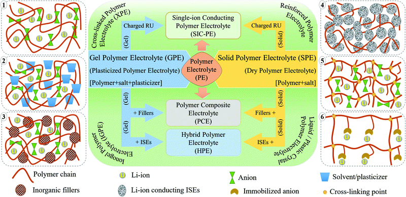
PEs can be broadly classified into dry polymer electrolytes (DPEs) and gel polymer electrolytes (GPEs), as shown in Fig. 4.190,191 However, the classification of PEs is not straightforward. Indeed, different terminologies have been interchangeably used for addressing similar PEs. For example, the term DPE is not so popular despite being used in several earlier reports since its inception by Wright et al. and Armand et al. in the 1970s. In recent times, the popular terminology of solid polymer electrolyte (SPE) has almost replaced the term DPE, which covers all the PEs that are free from any additional liquid/liquid-like plasticizer components. In PEs, if the ionic conduction is predominantly occurring in the liquid phase and is partially decoupled from the segmental motion of the polymer chains, they are called GPEs. The terminology of GPE is often used to represent plasticized and quasi-solid-state PEs as well. However, the distinction is not well-defined in the literature. If the liquid content in a PE is very low so that the ionic conduction mechanism is majorly coupled with the polymer chain segmental motion and hopping, such PEs are often called plasticized PEs. In such systems, the added liquid is acting mainly as the polymer host softener, which may not necessarily involve directly in ion conduction. In the case of quasi-solid-state PEs, the liquid content is in between GPEs and plasticized PEs, where the ionic conduction is significantly contributed by both the polymer host and the added liquid moiety. In any case, the liquid components (e.g., commonly used carbonate solvents in LEs) added into the polymer matrix are generally considered as plasticizers irrespective of their amount as they influence the polymer processing and their physical properties (Fig. 4(1)). Other than these conventional liquid plasticizers, molecules such as plastic crystals, liquid crystals, and oligomers of PEO and glymes with a low melting point [they are in a viscous/waxy state at RT and can be called liquid-like components] are also employed as plasticizers in PEs. Hence, the obtained PEs can also be included in the category of plasticized or quasi-solid-state electrolytes. PEs with plastic crystals and liquid crystals are often specifically called plastic crystal PEs (PCPEs) and liquid crystal PEs (LCPEs), respectively. In the context of this review, quasi-solid-state electrolytes and plasticized PEs are also considered in the category of GPEs as it is the most popular term used in literature reports. The terminology of plasticizer is not exclusively restricted to liquid/liquid-like components. Solid-plasticizers such as inorganic nanofillers (e.g., ceramic, glasses, etc.) are also used for tuning the properties of PEs. Even internal plasticization from side chains/functional groups of the polymer host is also possible. Such PEs with solid plasticizers/internal plasticizers are considered in the category of SPEs as the criterion of the absence of a liquid/liquid-like plasticizer component in the final PE is satisfied. However, even these SPEs can be easily transformed into GPEs by an activation process such as swelling/soaking or pre-incorporation by LEs. Ultimately, a variety of PEs such as polymer composite electrolytes (PCEs), hybrid polymer electrolyte (HPEs), single-ion conducting polymer electrolytes (SIC-PEs), reinforced polymer electrolytes, cross-linked polymer electrolytes, and so forth and so on are possible to be realized, which can be either SPEs or GPEs depending on the processing steps and components involved (Fig. 4).192–195 Detailed classification of PEs and further discussion on their properties are available elsewhere.65,66,172,196–199SPEs/DPEs
In a typical DPE, the salt is dissolved solely by the host polymer matrix without any external liquid/liquid-like plasticizers (Fig. 4(1)). The ion conduction occurs within the polymer host either by segmental motion or hopping, or both.73 PEO and several other commonly available polymer hosts such as poly(methyl methacrylate) (PMMA), poly(vinyl acetate) (PVAc), poly(carbonates), PVdF, PVdF–HFP, poly(acrylonitrile) (PAN), and so on are used for the preparation of DPEs.74 However, the ionic conductivity remains very low (<10−5 S cm−1 at RT) due to the inferior ion transport characteristics of these predominantly crystalline polymer hosts at ambient temperatures (PEs with nearly 100% crystallinity are also called crystalline PEs).200,201 Possessing a lower Tg value and improved polymer segmental mobility can facilitate ionic conduction in DPEs.202 This relationship between Tg and the amorphous nature of the polymer host fueled research on tweaking the polymer host's amorphous nature to enhance the ion mobility75,203,204 so that DPEs possessing ionic conductivity par with LEs are expected to be achieved.205,206 The amorphous character of a polymer host in a DPE can be tuned by adding solid-plasticizers, by introducing cross-links and interpenetrated polymer networks, or by constructing block copolymer architectures. Indeed, every approach reduces the crystallinity leading to the development of various sub-classes of PEs (shown in Fig. 4). Fig. 4 also schematically illustrates various types of PEs commonly discussed in the literature reports. As already discussed, this review opts for the term SPE to represent DPEs and all other related PEs devoid of liquid/liquid-like components in line with the modern-day literature reports.Innovation in SPEs can be achieved by adopting various interdisciplinary approaches. For instance, as the polymer host architecture can influence the electrolyte chemistry, especially the segmental motion of the polymer chains, creating novel polymer hosts such as block copolymers and polymer brushes, blending of two or more polymers, and preparation of semi- or fully-interpenetrated polymer networks, covalent organic frameworks (COFs), cross-linked polymers (Fig. 4(5)), and organic–inorganic hybrid copolymer systems are all of prime importance.207–212 An array of targeted, precise, and innovative polymer hosts and architectures can be synthesized using controlled polymerization techniques such as Reversible Addition Fragmentation Chain Transfer (RAFT) polymerization and Atom Transfer Radical Polymerization (ATRP) or simple anionic, cationic, and free-radical polymerization techniques.212–218 Besides, SPEs can be polymer-in-salt (rubbery electrolytes) and salt-in-polymer systems (a rarely used terminology). In the former, the weight percentage of the Li-salt exceeds 50 wt% of the polymer host, whereas it is vice versa in the latter.219–221
Preparation of SPEs as polymer nanocomposites (PNCs) with suitable inorganic nanofillers [e.g., SiO2, LiAlO2, MgO, MgAlO2, CeO2, TiO2, metal–organic frameworks (MOFs), MXenes, BN, clay minerals, etc.] has also been attempted, and such classes of electrolyte systems are known as polymer composite electrolytes (PCEs) or polymer nanocomposite electrolytes (PNCEs) (Fig. 4(3)).69,176,222–230 These nanofillers in the right proportions enhance the thermal properties, interfacial adhesion, and electrochemical and ion conduction characteristics. In PCEs, the nanofillers aid the Li+-ion transport through the functionalities (such as hydroxyl groups) and net charge present at the surface. These nanofillers also interact with polymer chains and modify their physical characteristics such as crystallinity, modulus, and flexibility. Thus, these nanofillers used in PCEs can also be considered solid-plasticizers as already discussed when used in low concentrations. Another family of PCEs, which has an individual identity and is gaining recent importance, is hybrid polymer electrolytes (HPEs). HPEs are produced by the interdisciplinary combination of organic and inorganic chemistry, where ISEs (e.g., LAGP, LLZO, LATP, etc.) are used as fillers so that they can also take part in ion conduction (Fig. 4(4)).230–235
The latest addition to the SPE family is polymeric lithium salts in which the mobility of anions is restricted by incorporating negative charge into the repeating units of either the polymer backbone or the pendant chain. They are mostly adopted for the preparation of single-ion conducting PEs (SIC-PEs) (Fig. 4(6)).236–238 In such systems, a high Li+-ion transference number (0.8 ≤ TLi+ ≤ 1) can be achieved due to the presence of immobilized anions as the only mobile species is the cation. Additionally, the salt concentration gradient (concentration polarization effect) is minimized at high charge–discharge rates due to the presence of only one type of charged species at the electrode|electrolyte interface. A similar effect can also be achieved by trapping the anions using anionic trapping agents such as boron-based Lewis-acids, macromolecules (e.g., calix[4]arene and calix[n]pyrroles), and anion-grafted/co-grafted inorganic particles, which can be incorporated into the polymer matrix as an additive to improve TLi+.64,239–245 Polymerized ionic liquid-based block copolymer hosts exhibiting a polyelectrolyte nature are also popular among SPEs.246–248 However, bringing the ionic conductivity of SPEs to the order of LEs is yet to be achieved. Still, all the aforementioned efforts have resulted in a pool of new polymers that can surpass the classical PEO as the primary host.
GPEs
The practical complexities related to the low ionic conductivity of SPEs are overcome by introducing the concept of GPEs. In a GPE,70 along with a polymer matrix and a conducting salt, a liquid solvent/liquid-like plasticizer is also used, which in turn increases the amorphous regions in the polymer matrix and enhances the ion transport (Fig. 4(2)).75,249 In other words, GPEs combine the advantages of both SPEs and LEs with high ionic conductivity and solid-like mechanical stability. This concept was first coined in 1975 by Feuillade et al.250 In contrast to SPEs, in GPEs (including plasticized and quasi-solid-state PEs), the ion conduction occurs through the synergistic contribution from both the plasticizer and the polymer phase. However, provided that the GPE is made from a surplus quantity of liquid solvent, the assistance from the polymer host towards ion conduction and mechanical property enhancement will be minimal. Nevertheless, the scope of GPEs is broad compared to SPEs, as many other electrochemical devices such as supercapacitors and solar cells prefer GPEs due to the possibility of achieving improved interfacial contact arising from the presence of a certain degree of LE-like character.251–253 The use of cross-linked, interpenetrated, and block copolymer hosts is explored to improve the LE or solvent retention capability in GPEs. However, the non-realistic addition of a liquid component to boost the electrochemical performance will compromise the safety aspects targeted for GPEs due to the decreased mechanical properties (e.g., low tensile strength, shear modulus, Young's modulus, etc.). Thus, the weight percentage of the liquid phase in GPEs is an important parameter to be taken into consideration. Indeed, an ideal GPE for LPBs is expected to possess high ionic conductivity with the least amount of liquid component incorporated in it. Similar to composite SPEs, composite GPEs (gel-PCEs) are also popular, which can to an extent compensate the disadvantages imposed by the presence of extra solvents.254–256In many cases, the polymer hosts used in SPEs are also used for the preparation of GPEs.63,257–259 Carbonate solvents, glymes, low molecular weight poly(ethylene glycol), etc., are used for the activation/plasticization of the polymer matrix.260–262 Besides, room-temperature ionic liquids (RTILs) are used as a safe alternative to low boiling point plasticizers, and several studies have been carried out in this direction.263–267 RTILs as a plasticizer are an interesting case for several reasons. Firstly, these organic salts are liquid at RT, whereas a conventional salt like LiTFSI is solid. Secondly, RTILs can act as a liquid plasticizer to reduce Tg of the polymer host and, at the same time, can facilitate ion transport. Finally, these are high boiling solvents with negligible vapor pressure; hence, even after being employed as an organic liquid plasticizer, fire hazards can be avoided. The addition of RTILs into a polymer matrix and the classification of the resulting PE is an unresolved debate yet. In many literature reports, it is considered as a quasi-solid-state PE, but several others referred it as an SPE since RTIL by itself is a salt. The term ionogel PE (IGPE) is also often used to consider it as a separate class of PE.268,269 The major issues with IGPE systems are their high cost, low purity, and low TLi+ value, and such problems must be addressed to implement these systems for commercial applications. Even polymeric ionic liquids (PILs) acting as a host and salt in GPEs and SPEs are also finding attraction among researchers.270–272 Other solvents like H2O, acetonitrile (ACN), dimethylformamide (DMF), N,N-dimethylacetamide (DMAC), and N-methyl pyrrolidone (NMP) are also used in GPEs for specific applications.273–277
The advantages of SPEs over GPEs include their high mechanical stability and enhanced compatibility with the Li-metal anode owing to the absence of a liquid phase. Although the liquid phase in GPEs may often undergo unwanted parasitic reactions over the Li-metal anode and destabilize the interface and interphase, the liquid-like ionic conductivity of GPEs is the utmost advantage due to the enhanced ion transport characteristics. Despite the trade-off between GPEs and SPEs in many aspects, both systems are promising to be used for the commercial production of LPBs. Recently, PEs have found applications in microbatteries, and flexible- and printable-LBs.278–281 Additionally, other metal-ion (Na+, Zn2+, Mg2+, etc.) conducting PEs are also being noticed with the surge in interest towards batteries beyond lithium chemistry.282–289 This underlines that the concomitant development of both SPEs and GPEs is indeed crucial for pushing the further development of LPBs and other EES technologies. It is worth mentioning that LPBs are already under commercialization by companies like IONIC MATERIALS INC,290 A-123 Systems, DNK Power,291 Panasonic, LG Chem, and Bolloré.292 In the next few years, widespread interest in LMPBs with SPEs is expected to grow many folds also for EV application.293,294
4. Intricacies of interfaces and interphases, and related challenges in PEs
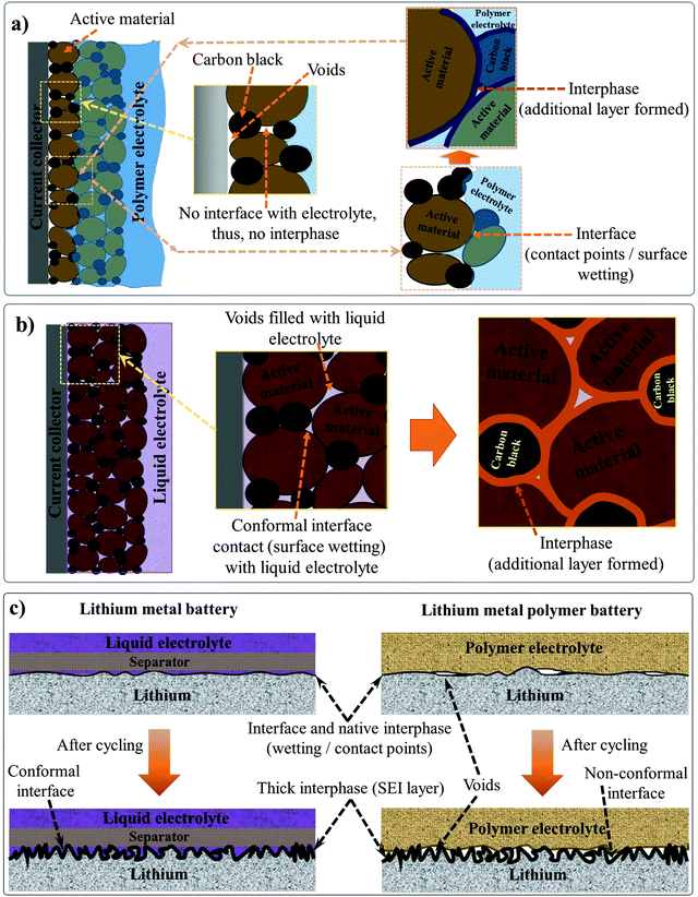
The electrode|electrolyte interfaces and interphases are two critical components influencing the electrochemical performance of any LB cells. Interfaces are the regions in an LB cell where the electrode and electrolyte are in direct contact with each other. On the other hand, the interphase refers to a desirable passivation layer, which is formed over the electrode surface by electrochemical processes taking place at the interface. Interphases have a definite chemical composition that prevents direct contact between the electrode and electrolyte components, but, at the same time, ensures facile Li+-ion transport. The interface qualitatively indicates the extent of contact between the electrode and electrolyte species inside an LB cell. Electrode|electrolyte interfaces in LBs are of two types: the (i) anode|electrolyte interface and (ii) cathode|electrolyte interface.295 Accordingly, the two types of electrode|electrolyte interphases formed over the anode and cathode are known as the SEI and CEI, respectively. An ideal electrode|electrolyte interface indicates the complete wetting of the electrode particles present at the surface and bulk regimes of the composite electrode film irrespective of the coating thickness. Ideally, achieving maximum interfacial contact and active material utilization within an LB cell requires electrolyte impregnation into pores distributed in the sub-micron regimes, those including nanopores, mesopores, and micropores of the electrode particles, which is indeed challenging. Indeed, the interface and interphase are two interrelated features since the interphase can only be formed at the interface between the electrode and electrolyte. Therefore, in any battery cell, the first step is attaining a conformal electrode|electrolyte interface (simply, good wetting). Later, the electrochemical processes occurring at the interface lead to the formation of conformal interphase layers (SEI and CEI), hence impeding both the electrode and electrolyte components from further degradation or decomposition. However, all interphases are not equally useful in avoiding parasitic reactions between the electrode and electrolyte or providing interfacial stability within the LB cell. Attaining a conformal interface can ensure an equally conformal interphase. However, the nature and the quality of the interphase is ultimately decided by the electrode and electrolyte components, and the cell operating conditions.Generally, the SEI and CEI are considered desirable interphases and very important for the functioning of LBs. However, undesirable interphases formed by parasitic reactions between the electrode and electrolyte do not lead to ideal SEI- and CEI-like characteristics. The favorable features of SEI and CEI are: (i) ionically conducting, (ii) thin and uniform, (iii) chemically and thermally stable, (iv) capable of absorbing the stress from the volume change occurring during the cycling process, (v) capable of avoiding leaching of active electrode materials, (vi) electronically non-conducting, and so forth and so on. As one of the authors of this review emphasized earlier in one of his influential perspective articles on interphases, ‘the SEI and CEI formed at the electrode surfaces are thin solid electrolytes, but the fact is often ignored.174 Indeed, interphases are one of the most important but least understood components of a battery cell. In most of the literature, the interphases in an LB cell are depicted as a superficial layer formed on the surface of the composite electrode film. However, it is not representing real-world conditions since the interphase covers not only the surface of the composite electrode film but also the surface of individual electrode particles (Fig. 5a).
The physical interaction between a hypothetical PE and a thick and porous LB electrode (anode/cathode) can be considered as a model system for understanding the electrode|electrolyte interface and interphase, as presented in Fig. 5a. Here, the regions accessed by the PE are denoted as retaining a conformal electrode|electrolyte interface, whereas the regions inaccessible to the electrolyte are indicated as possessing non-conformal electrode|electrolyte interfaces. A non-conformal electrode|electrolyte interface within the electrode reduces the overall active material utilization and maximum achievable energy density. The formed interphase in the interface regions, at which the PE is holding excellent contact with the electrode material, is also highlighted. Fig. 5a concludes that in a typical scenario, a PE cannot offer an ideal electrode|electrolyte interface or interphase, especially in cases when used as a film sandwiched between the electrodes. However, in LEs, the free-flowing nature and low viscosity help in the adequate wetting of the electrode particles at the surface and those buried beneath the composite electrode film (Fig. 5b). The LE can easily impregnate into the bulk-regimes of the porous electrode matrix, providing an extended conformal electrode|electrolyte interface and interphase, in turn ensuring inter-particle Li+-ion transport and maximum active material utilization. Therefore, during the transition from LEs to PEs, achieving an electrode|electrolyte interface and interphase similar to LE is challenging, especially with typical porous and thick electrodes. The inferior electrode|electrolyte interface is one of the most fundamental challenges to be solved in LIPBs, which leads to inferior electrochemical performance when compared to conventional LIBs.
In the case of LMPBs with a flat Li-metal anode of relatively low surface area and porosity compared to graphite, achieving a conformal anode|electrolyte interface, which is more or less similar to conventional LEs, is often not challenging with a PE (still, an externally prepared PE film cannot precisely mimic the Li-metal|LE interface as illustrated in Fig. 5c, where voids would still exist at the Li-metal|PE interface). However, it should be noted that the high reactivity of Li-metal can decompose the PE components during cycling. Additionally, the stress arising from the volume changes on the Li-metal surface during the continuous lithium plating/stripping process will destabilize the interface and interphase (Fig. 5c), a similar scenario to the case of an LE-LMB (Fig. 2 and 5c). During continuous cycling, it is possible that the relatively smooth Li-metal surface eventually turns rough and uneven due to HSAL growth, and the continuous electrolyte decomposition leads to the formation of a thick interphase. HSAL nucleation and the thick interphase can lead to cell failure with time, which is more severe in LE-LMBs but can be present in LMPBs also with an otherwise inefficient PE. Hence, LMPBs demand PEs that can provide a stable interface without compromising the Li-metal|electrolyte interphase. As already discussed in Section 3, a PE with a high Young's modulus value may be suitable to stabilize the Li-metal|PE interface and interphase. However, the chemical composition of the PE and its compatibility with Li-metal are also equally important to avoid any detrimental parasitic reactions, which can lead to the formation of undesirable interphases without typical SEI features. Even for those PE films providing a good interface and interphase at the Li-metal anode, the challenges of maintaining the ideal interface still persist with the porous and thick cathode. In conclusion, novel cell fabrication strategies and polymerization techniques should be considered and implemented for LIPBs and LMPBs with smart PEs that can offer LE-like (or close to LE-like) interfaces and interphases for the flourishing of LPBs in general.
4.1 The ex situ process and device fabrication thereof
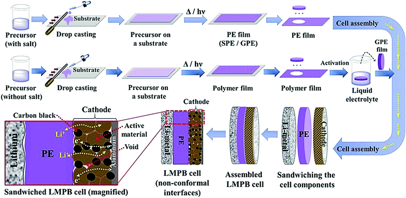
The conventional approach for the fabrication of LPBs involves multiple steps in which a PE is externally prepared as a self-standing film,296–298 followed by sandwiching between the electrodes.299–303 For example, the preparation of a PE film by heat-/light-induced polymerization and the subsequent assembly of an LMPB cell are presented in Fig. 6. Here, the primary requirement is a precursor solution (also called reactive mixture, reactive solution, or merely precursor) containing polymerizable monomers (also including oligomers: they are polymerizable molecules made of a few monomer units, examples include dimers, trimers, tetramers, etc.), a conducting salt and a suitable polymerization initiator (molecules that initiate the polymerization process when provided with the right conditions). The presence of an electrolyte solvent/plasticizer (solid/liquid/liquid-like) is optional, depending on whether an SPE or GPE is of interest. Later, the precursor is cast on a flat surface, and, following the polymerization process, a PE film with the desired thickness is obtained. In many cases, a polymer film is prepared from the precursor in the absence of electrolyte components (salt and plasticizer) and later subjected to activation by a swelling (soaking) process in an LE to produce an ionically conducting GPE.304 In any case, the prepared PE film is used in the sandwich configuration, where it plays the additional role of the separator as well. Such a strategy of LPB cell fabrication using an externally prepared PE film is often given by the term: ‘the ex situ fabrication of LPB cells’ (simply, the ex situ (polymerization) process).The preparation of PE films, as depicted in Fig. 6, can be called a bottom-up approach since the polymer host is evolved from a precursor consisting of basic constituent units of reactive monomers/oligomers. Polymerization methods such as free-radical polymerization, ionic polymerization, condensation reactions, click chemistry, and so on are finding immense attraction among researchers for the preparation of PE films by such a bottom-up approach.300,304–307 Indeed, these polymerization reactions can be triggered by energy sources such as heat, ultraviolet (UV)/visible light irradiation, and microwave/infrared/γ-ray exposure. Bottom-up polymerization methods are suitable to prepare and tune the properties of homo-polymers, copolymers, and cross-linked or even reinforced SPEs and GPEs. In fact, this bottom-up approach by radiation-induced polymerization came into the limelight with the work of Abraham et al. in 1995, where a reinforced GPE film was prepared using a Celgard separator soaked with a PE precursor made of a tetraethylene glycol diacrylate cross-linker, a carbonate-based LE, and a photo-initiator.308 This work inspired several successive studies that later employed UV-polymerization for the production of various types of PEs.309,310 The advantage of the bottom-up approach is that any additional solvents other than those required for the plasticization of the PE can be avoided as most of the monomers/oligomers are inherently capable of dissolving the Li-salt, hence minimizing the wastage of solvent. However, if required, a small amount of solvent can be used during the PE processing, which can be evaporated off in the subsequent steps depending on the requirement that a plasticized PE or SPE is required. Ultimately, the bottom-up approach of PE film preparation is applicable in both solvent-supported (wet) and solvent-free (dry) conditions.
In conventional dry/solvent-free processing of PE film preparation by the ex situ process, a polymer is melted above the melting point (Tm), and then electrolyte components are added to the melt.311 Depending on the type of components added, and the involvement of the activation step, an SPE or GPE film can be prepared. Thus, this melting-induced dry processing can be considered a top-down approach as the polymer host is directly used to prepare the PE film, unlike the on-site conversion of monomer/oligomer units to PEs by the bottom-up approach. One of the disadvantages of this process is that the desired mixing can be achieved only at high temperatures under high mechanical shear. Also, the salt or even polymer decomposes at such high temperatures and mechanical stress conditions, and expected results are often not achieved. A modified version of this method called melt-pressing is also popular.197,312 In this process, the polymer host and other solid-components such as salts and fillers (preferably in the powdered form) are mixed and ground well until a homogenous blend is obtained. Later, the mixture is hot-pressed close to the melting point (Tm) of the polymer matrix by keeping it between two Teflon (PTFE) sheets (or stainless-steel plates or other substrates) so that a PE film or pellet can be prepared. However, in this method as well, the temperature-induced decomposition of the electrolyte components is mostly unavoidable.
There are several conventional wet (solvent-supported) processes used for the preparation of PE films.72,197,313 In a typical wet process, the polymer is dissolved in a suitable solvent with or without the presence of a salt and other solid-additives (since a polymer is directly employed, these methods can also be considered in the category of the top-down approach). The cast membrane, following vacuum drying and evaporation of the solvent, can be either directly used as an SPE (if a salt is present) or activated by an LE. This activation process induces plasticization of the polymer chains due to the interaction with the salt and the plasticizer components. Therefore, Tg is reduced, while the flexibility of the overall PE is increased. The swelling time or rate is controlled to obtain mechanically stable GPE or plasticized/quasi-solid-state PE films. The swelling also determines the amount of plasticizer and salt components present in the PE, which decides the overall electrochemical properties.314–316 For example, the ionic conductivity is increased with an increase in the LE content; at the same time, swelling of the polymer film induces volume expansion due to the uncoiling or unpacking of the polymer chains from the ordered phases (crystalline) of the polymer matrix. This phenomenon decreases the mechanical properties; nevertheless, the solvent uptake increases the mobile phase within the polymer electrolyte. The method developed by Sony Co. in the year 1999 for the preparation of PVdF–HFP-based GPE films activated by carbonate-based LEs is popularly known as the Sony process for GPE preparation.317,318
Extraction–activation methods for the preparation of GPE films are a commercially important wet process (top-down) developed by Bellcore.319,320 In this method, the polymer is mixed with a slurry of electrode material in the presence of a plasticizer and coated over the current-collectors. Then the plasticizer is extracted, followed by wetting the electrodes by an LE during cell assembly. However, this method is tedious and dangerous, owing to the use of the toxic dibutyl phthalate (DBP) plasticizer. The approach is further improvised in such a way that the extraction step is avoided and this is popularly known as the phase-inversion method.320–322 Bellcore is also credited with the early models of LIPBs, which were commercialized in 1999 under the name PLiON (plastic lithium-ion battery).319,323 In several reports, viscous GPE solutions are also used, which are often directly cast over the electrode surface for electrochemical device fabrication (e.g., PMMA dissolved in LiClO4/PC solution).251,324 This method is found to improve the electrode|electrolyte interface compared to the case when PE membranes are otherwise used as films. However, even this approach fails with thick electrodes due to the size-mismatch of the pores in the electrode material and the high molecular weight of the polymer chains.325,326 Moreover, this method intensively compromises the ultimate aim of achieving a high performance and mechanically stable GPE, which does not lure the research community beyond the lab-scale.
Although PE films that are ex situ processed are essential and significant in LPBs (even commercialized to an extent), absolute improvement in terms of the electrode|electrolyte interface/interphase to match with that of an LE (Fig. 5b) can be envisaged when looking towards the future. For example, when a PE film is used in the ex situ process, the electrode|electrolyte interaction is primarily confined to the surface but not to the bulk of the electrode (see Fig. 5a and 6). The ex situ process leads to low active material utilization in LPBs, resulting in a reduction in the maximum achievable energy density. In a battery electrode, it is vital to maintain an excellent electronic and ionic flow within the composite electrode (Fig. 6 magnified cell) so that the redox reactions leading to the charge–discharge process can occur with the lowest overpotential or activation energy. Recent modeling studies also emphasize the significant role of Li+-ion transport within the composite electrode matrix, which largely influences the overall performance of LBs, especially at higher current rates (power density) and with thick electrodes (energy density).327 The low rate capability in the case of LPB cells fabricated by the ex situ process, especially in thick electrodes, is due to the non-accessibility of the PE components to the electrode particles buried beneath the surface of the composite electrode film and the electrode pores. In Fig. 5a and 6, the regions in which the electrolyte accessibility is minimal are represented as void spaces. Such void spaces indicate that ex situ processed PE films are incapable of emulating the efficient electrode|electrolyte interface/interphase similar to conventional LEs.295,328 Thus, inter-particle Li+-ion transport in LPBs with thick electrodes can only be achieved with the help of an ion conducting (e.g., PE) medium present within the electrode bulk.
4.2 The in situ process and device fabrication thereof
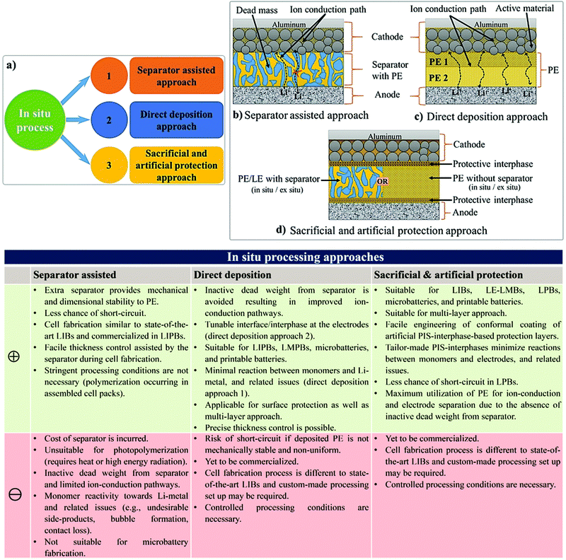
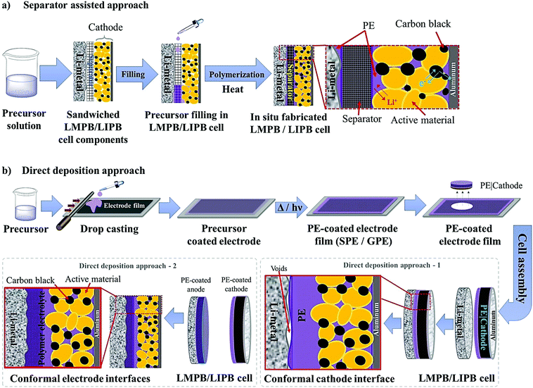
To overcome the limitations associated with electrode|electrolyte interfaces and interphases in LPB cells using the ex situ process, ample modifications are proposed that can be implemented from the PE synthesis step itself. One such strategy is called ‘the in situ fabrication of LPB cells,’ or simply, the ‘in situ (polymerization) process,’ which has received considerable attention in recent years.329–334 The in situ process involves the single-step generation of a PE ensuring an effective electrode|electrolyte interface and interphase extended to both the surface and bulk particles of the composite electrode. The in situ processing of LPB cells is often carried out in three different ways (Fig. 7a):(i) separator assisted approach (Fig. 7b and 8a)
(ii) direct deposition approach (Fig. 7c and 8b)
(iii) sacrificial and artificial protection approach (Fig. 7d).
The 1st and 2nd approach directly address the fabrication of LIPBs and LMPBs. The 3rd approach is mainly used for the production of conformal protective interphase layers over the active material and conductive carbon of the composite electrode so that the performance of LE-based LIB and LE-LMB cells can be improved. Also, this protection approach can be improvised for the fabrication of LMPB and LIPB cells through an emerging process called a multi-layer approach, as explained in Section 4.2.3.
The first step of the in situ process is the preparation of a precursor similar to that of the ex situ process, as shown in Fig. 6, consisting of polymerizable monomers/oligomers and a conducting salt in the presence of a suitable initiator. Solid- or liquid- plasticizers and additives can also be introduced into the precursor to fine-tune the physicochemical and electrochemical properties, including interphase formation. The in situ process is usually carried out by impregnating the coated composite electrode with the precursor, which is later polymerized using an external energy source (e.g., heat or light) so that the PE generation takes place internally within the pores and voids of the electrode coating. The infusion of the electrode by a less viscous precursor in the liquid state, which is similar to an LE, helps in (nearly) saturating the sub-micron pores with low molecular weight monomers, Li salt, solvent, and soluble additives. The impregnation of the precursor followed by the polymerization step ensures an intimate and compelling electrode|electrolyte interface/interphase in the final battery cell close to that offered by an LE (Fig. 5b).325,326,335 It is highly desirable that the size of the molecular species present in the precursor is comparable to the pore-size/volume of the electrode materials for allowing maximum impregnation and a suitable electrode|electrolyte interface as well as conformal and uniform interphase formation.
The factors, challenges, and advantages pertaining to the interface and interphase formation in the context of the in situ process and LPBs, in general, are summarized below.
(a) PE impregnation depends on the viscosity and surface energy of the precursor, bulk porosity and thickness of the composite electrode film, inherent porosity of the electrode materials, continuity of pores/voids, and processing conditions such as temperature and vacuum. The greater the electrolyte impregnation, the higher the active material utilization.
(b) The surface characteristics of electrode materials also determine the interface and interphase. Factors such as the native layers, surface area, surface chemistry, and surface energy of individual electrode components are essential. Comparable surface energy of the electrode and electrolyte precursor ensures effective impregnation and a nearly liquid-like interface throughout the electrode (at the surface and the bulk).
(c) The purity of electrode and electrolyte materials influences the control and stabilization of the interphase. Additive chemistry that is already established for LEs can be used for interphase tuning. The effectiveness of interface formation (improved wetting), compounds formed due to the decomposition/consumption of the electrolyte (e.g., additives, monomers, salt, and plasticizer) components, nature of byproducts formed (e.g., gaseous or nongaseous, corrosive or non-corrosive, and catalytic or noncatalytic), reactivity of monomers and oligomers with the electrode components, etc., also affect the stability of the interphase. Interphase characteristics such as the uniformity, thickness, mechanical properties, grain boundary characteristics (especially for inorganic SEI/CEI layer), and related ion transport properties affect the overall cell performance.
(d) Changes to which the electrodes are subjected during electrochemical cycling (e.g., surface area and volume changes of the cathode/anode active materials, continuously evolving surface morphology of the lithium-metal anode, changes in the chemical composition of the electrode material and electrolyte, etc.) may affect the quality of the interface/interphase. The physical changes associated with the electrodes may be accompanied by the rupture/delamination of the interphase and a loss of contact (interface) between the electrode and electrolyte. In situ processed self-healing PEs may be envisaged to recover/maintain suitable electrode|electrolyte interfaces and interphases.
(e) The ionic and electronic transport within the composite electrode between individual electrode particles, or, in other words, the inter-particle ion diffusion, is essential to achieve high energy and high-power batteries. However, the PE must not hamper the electronic transport between the electrode particles.
(f) Visualizing the processes taking place at the electrode|electrolyte interfaces and characterization of the formed interphase are indeed essential to help advance existing LBs with the rational development of tailor-made electrode and electrolyte formulations. The characterization of the solid|liquid interfaces in state-of-the-art LIBs is relatively well-established with post-mortem analysis of cycled cells using techniques such as NMR, XPS, Raman analysis, XRD, microscopy, etc., in ex situ experimental conditions. However, it is crucial to investigate the interfacial processes under operando and in situ conditions in a non-destructive fashion. For this purpose, the existing in situ and operando characterization methods (XPS, Raman analysis, NMR, microscopy, etc.), which are designed mostly for the characterization of LE-based LBs, should be modified to make them compatible for thorough analysis of the more challenging solid|solid interfaces in solid-state batteries (PE- and ISE-based LBs). Advanced X-ray tomography techniques are also potential candidates for non-destructive investigation of solid|solid interfaces.
The in situ processes using free-radical polymerization by means of thermal- and photo-curing methods are extensively explored for the fabrication of both LMPBs and LIPBs on the lab-scale.336–340 Free-radical photo-polymerization is usually carried out in a UV-chamber under inert atmospheric (preferably) conditions, whereas ordinary laboratory ovens can be used for the thermal polymerization process.307,341–343 However, other energy sources such as gamma (γ)-rays,331 visible light, and lasers344 are also used for initiating various types of polymerization reactions, but are not as popular as the former heat- or UV-induced polymerization methods. Apart from the free-radical induced in situ polymerization process, other methods such as ionic polymerization,345–347 condensation polymerization,348,349 and electropolymerization are also receiving attention nowadays.
The number of polymerizable functionalities (n) (e.g., polymerizable reactive moieties such as a double bond, epoxide units, and thiol) of monomer or oligomer molecules incorporated in the precursor significantly influences the ion transport and mechanical properties of the formed PE. Depending on the ‘n’ value, the polymer hosts in the PE can be either cross-linked or non-cross-linked. Indeed, the physicochemical characteristics of PEs are ultimately dependent on the type of polymer host. A non-cross-linked polymer host is formed from a precursor employing polymerizable species (monomer/oligomer) with an ‘n’ value of 1 (mono-functional). If a single type of mono-functional monomer/oligomer molecule is used in the precursor, the obtained polymer host can be called a non-cross-linked homo-polymer (linear or branched). On the other hand, a combination of two or more different types of mono-functional monomer/oligomer molecules produces a non-cross-linked copolymer (linear or branched). The polymer chains in a non-cross-linked polymer host are flexible and dynamic, facilitating ion conduction in a PE. The non-cross-linked character may also lower the physical properties such as softening, melting, and flow-temperature points. Thus, a non-cross-linked PE may not retain the mechanical properties in a wide temperature range. In most cases, when a non-cross-linked homo-polymer or copolymer host is used in a PE, a thicker PE sample is preferred to avoid internal short-circuit. When the value of ‘n’ is ≥2 (multi-functional), cross-linked polymer hosts are formed. Here, a single type of multi-functional or a combination of different kinds of multi-functional monomer/oligomer molecules can be employed to prepare cross-linked polymers. If the cross-linking density (a measure of cross-linked points per unit volume, unit: mol cm−3)350,351 is very high, it can affect the polymer chain dynamics and reduce the ionic conductivity of the associated PEs. However, a high cross-linking density beyond a certain limit will enhance mechanical properties such as toughness and brittleness and, in turn, reduce flexibility. Thus, a certain degree of flexibility is always desirable for the polymer host to facilitate ion conduction. Besides, if the polymer host interacts with other electrolyte components such as a salt, plasticizer, etc., the physical properties may vary.
Another approach of preparing relatively flexible cross-linked PEs is by employing a precursor made by combining judiciously selected mono- and multi-functional monomer/oligomer molecules. Such systems consist of a polymer backbone with cross-links inducing a connection between several individual linear/branched long polymer chains derived from the mono-functional molecule present in the precursor. They can often display better flexibility than tightly cross-linked polymer hosts due to the reduced cross-linking density. If internal plasticization from the pendant chains of monomer/oligomer molecules is present, the dynamics of the polymer chains can be further enhanced, favoring ion transport. Depending on the concentration of multi-functional monomer/oligomer molecules present in the precursor, the cross-linking density of polymer hosts can be fine-tuned to achieve the desired flexibility and toughness, optimizing the ion conduction, electrode wetting behavior, and mechanical stability. Considering the mechanical flexibility that long-chain oligomer molecules [e.g., acrylate, methacrylate, and allyl and vinyl ether derivatives of poly(ethylene glycol), etc.] can provide to the polymer hosts, they are more prevalent in the preparation of PEs over small-sized monomers [e.g., methyl methacrylate (MMA)].
A detailed explanation of the various types of in situ processing approaches is discussed in the following sub-sections.
The separator assisted approach is not always useful in the context of an LMPB since certain types of monomers/oligomers (e.g., acrylates and methacrylates) present in the precursor may undergo undesirable parasitic reactions over the reactive Li-metal surface, hence producing unwanted and unsuitable passivation layers. Therefore, the chemical aspect of the monomers/oligomers such as compatibility with the electrode components also should be considered while selecting the PE components and the polymerization method. However, if monomers/oligomers that are compatible with Li-metal or a precursor with SEI forming additives are used, the separator assisted in situ approach can find immediate applications in LMPB fabrication as well. As of now, this method is generally considered to be handy and extensively used in the fabrication of LIPBs. Indeed, the separator assisted approach is primarily used to evade leakage of the LE from the battery pouch so that smart, lightweight, and thinner packaging can be used for battery construction. For instance, the separator assisted in situ process was adopted by Sanyo in 2002 for the industrial production of LIPBs, as displayed in Fig. 9.352,353 The in situ process implemented by Sanyo is known as the Sanyo process (see the Fig. 9 caption for details). In the preparation of most laboratory-grade LPB cells, separator pre-soaking in the precursor is used instead of filling in a pre-assembled pouch- or coin-cell. Ultimately, the separator assisted approach is not useful in customized LPB cell designs such as microbatteries as the use of an additional separator is not feasible since it may add to the overall size of the microdevice.
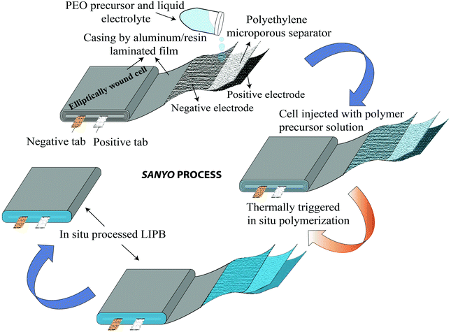 | ||
| Fig. 9 Sanyo process (ref. 352 and 353) for the fabrication of an LIPB cell by the separator assisted approach. In this method, typically, a positive electrode using LCO, a negative electrode using graphite, and a polyethylene microporous separator are wound together in an elliptical fashion. This cell element is enclosed in a casing, and a precursor containing an LE [lithium bis(pentafluoroethanesulfonyl) amide [(LiN(SO2C2F5)2, LiBETI] dissolved in a carbonate-based solvent] and an ethylene oxide-based precursor are injected. Then, the cell is heated to induce the polymerization of the precursor. | ||
For LE-based LBs (LIBs and LE-LMBs). For understanding the concept of the sacrificial and artificial surface protection approaches based on the in situ polymerization process, it is essential to define a new term called ‘polymeric ionic-skin (PIS)’. An ionic-skin can be considered as a conformal and thin coating of an ion conducting layer (nanometre to few micrometer thick) formed over the anode/cathode active materials as well as other electrode components (conducting additives such as carbon). Such a layer is formed on the surface and the bulk of the electrode particles of an LIB/LE-LMB/LPB cell during electrochemical cycling. Also, these layers can be artificially prepared before cell fabrication. In a broader perspective, all SEIs and CEIs can be considered in the category of inorganic, organic, or composite ionic-skins that are capable of protecting the electrode as well as electrolyte components from several undesirable electrochemical events. Provided that these SEIs/CEIs also include polymeric components that are formed from the chemical/electrochemical reactions of LE solvent molecules or additives, they can be called PIS-interphases. In the same perception, the classical SEI and CEI layers formed from the decomposition/polymerization of carbonate solvents/additives [PC, EC, fluoroethylene carbonate (FEC), vinylene carbonate (VC), and so on] at the electrodes of an LB cell include materials that are polymeric and can be called PIS-SEIs and PIS-CEIs, respectively.88,355–357 Indeed, the term PIS is a metaphor for the SEI/CEI formed over the electrode, which is polymeric in character. Such polymer formation due to the uncontrolled decomposition of the electrolyte solvents can be called sacrificial polymerization due to the destruction of the structure of these solvent molecules, which even produces unwanted side products. These polymeric components may have variable molecular weight and not well-defined physicochemical characteristics. However, when appropriate molecules are added as additives and targeted polymeric materials are conformally formed at the surface of the electrode components, such a process can be called the artificial polymerization process, which is rather precise and target specific compared to sacrificial polymerization. In other words, surface protection by the PIS-interphase formed by the sacrificial polymerization of the LE solvent molecules is a universal phenomenon occurring inside all organic LE-based LBs and other alternative Li-free battery cells. Indeed, these polymerizations are truly electrochemical in origin. Therefore, the generation of a PIS-SEI or PIS-CEI during the formation cycles of LIB cells can be considered the simplest example of sacrificial surface protection induced by the in situ (electrochemical) polymerization process. In the cases mentioned above, the formation of a PIS-interphase occurs within the assembled cell, and features such as thickness and composition cannot be often controlled. The controlled deposition of PIS-interphases can be achieved from a precursor-based LE in a standard three-electrode or two-electrode electrochemical cell by polymerization initiated by electrochemical oxidation or reduction processes on the electrode of interest.
In addition to the electrochemically assisted in situ processing of artificial PIS-interphases, other polymerization methods (free-radical, ionic, and condensation polymerization) are also employed to generate artificial polymeric surface protection layers. Here, the first step involves the coating of a precursor containing suitable monomers/oligomers over the composite electrode film, like that of the direct deposition approach. Later, the polymerization reaction is initiated by light, heat, or other means depending on the type of monomer/oligomer used. The motive of the in situ polymerization process in this approach is not the formation of a thick PE layer that can separate the two electrodes but a conformal PIS-based ultra-thin protection layer. Even if a precursor in the absence of electrolyte salt is used, the formed non-conducting polymer layer on contact with the LE eventually converts to a PIS by an activation (swelling) step within the LE-based cell.
Mostly, the in situ processing of artificially formed PIS-SEIs/PIS-CEIs as surface protection layers is very useful in LE-based LIB/LMB cells to prevent the direct attack of LE components that may degrade the electrode during cycling (e.g., transition metal dissolution, electrode particle cracking, etc.). Besides, these layers can reduce or even altogether avoid the continuous decomposition of an electrolyte by the electrode components. In other words, an artificial PIS-SEI/PIS-CEI is mutually beneficial for both the electrode and electrolyte. Once this conformal coating by the PIS is achieved over the electrode, the full cell can be fabricated by using a conventional LE. Hence manufactured LB cells cannot be included in the category of LPBs due to the use of traditional LEs except for the presence of a thin PIS-interphase coating. However, by this method, stable electrochemical cycling with Li-metal has been even realized in state-of-the-art LE-based LMBs (LE-LMBs), unlike the case with an unprotected Li-metal anode. As part of this review, the reports in the context of surface protection of LBs using an in situ processed PIS-interphase are also thoroughly discussed as this has never been reviewed elsewhere.
For LMPBs and LIPBs (multi-layer approach). The artificial/sacrificial protection approach can be extended to LIPB/LMPB fabrication by an emerging process called the multi-layer approach. In the multi-layer processing of LPBs, the first step involves the individual electrodes being protected by an in situ processed PIS-interphase. A relatively thick subsequent PE layer (over the PIS) can be prepared either by the direct deposition approach or as an ex situ processed PE layer/film (Fig. 7d).361,362 Here, the electrode|electrolyte interphase is taken care by the PIS, whereas the thick PE layer effectively separates the two electrodes facilitating ion transport. The multi-layer approach is, in fact, a combined strategy, where the surface protection approach is in conjunction with the direct deposition or the ex situ process. Due to the presence of multiple electrolyte layers (first layer of a PIS-interphase and a subsequent layer of a PE), this approach is also called layer-by-layer fabrication of an LIPB/LMPB. Various types of polymer, monomer/oligomer, salt, plasticizer, or additive chemistry can be used for individual layers; hence, tailor-made LPBs can be prepared. Research in this direction is indeed rare. However, multi-layer processed LPBs are strong candidates for the industrial-scale production of the next generation of LMPBs or LIPBs. The advantages and disadvantages of the three different types of in situ processing approaches are summarized in Fig. 7e.
The following sections will explain the individual cases of the in situ processing of LPBs and the role of each study in further improving the field.
5. In situ process by photo-/thermal-induced free-radical polymerization
In this section, relevant reports in which the in situ processing of LB cells is carried out by a free-radical polymerization reaction using photo- or thermal-curing are comprehensively analyzed and summarized according to the type of monomers as well as the type of in situ processing approach adopted. Separator assisted, direct deposition, sacrificial and artificial protection, and multi-layer processing approaches are discussed in detail.Free-radical polymerization is usually carried out using energy sources such as heat, UV light, visible light, gamma rays, microwaves, infrared (IR) rays, and so on.344,371 Using these techniques, various types of linear and branched homo-polymers, copolymers, and cross-linked systems can be produced within a few seconds to a few hours. A typical free-radical thermal/photopolymerization reaction needs monomers or oligomers having an unsaturated functional group (vinyl or allyl) and an initiator. In general, free-radical photo-initiators are of two types, namely Norrish Type I and Norrish Type II.372 The photo-initiator 2-hydroxy-2-methylpropiophenone (HMPP) is a type I system that, on UV exposure, decomposes into radicals by the homolytic cleavage of the excited (high energy state) α-carbon bond and produces two radical fragments (initiating free-radical, I˙). These radicals react with other reactive monomers/oligomers to form an initiating radical chain. Indeed, the free-radical initiator attacks the loosely bound pi-electron cloud of the double bond of the monomer/oligomer so that the initiating radical chain is formed. Later, the initiating radical chain further continuously reacts with the other monomer/oligomer molecules present in the reaction mixture. This step is called the propagating reaction. Finally, this propagating chain is terminated either by removing the energy source, by side reactions, or by the exhaustion of the reactive monomer/oligomer species. A similar reaction pathway involving the direct cleavage of initiator species to free-radical fragments and subsequent propagation is followed in thermally initiated free-radical polymerization as well, where peroxide (e.g., benzoyl peroxide, BPO) and azo compounds (e.g., azobisisobutyronitrile, AIBN) are the most popularly employed free-radical initiators. The mechanism of a typical free-radical thermal-/photo-polymerization reaction involving the aforementioned steps is displayed in Fig. 10a.358 It is not always necessary that the initiator molecule on excitation by an external stimulus such as light should undergo direct cleavage to fragment into free-radicals and then attack the pi-electron cloud of a double bond to propagate the polymerization reaction as shown in Fig. 10a. For example, specific free-radical initiators (e.g., benzophenone) can be sensitized372 by photo-irradiation and abstract an active hydrogen atom from the sp3 hybridized carbon of a suitable molecule such as PEO (namely, a donor molecule) to generate a carbon free-radical that can take part in the polymer chain propagation/cross-linking reaction,359,373,374 and these are called Norrish type II initiators. Such hydrogen abstraction induced generation of free-radicals is useful for introducing cross-links in otherwise linear PEO chains.362,375 An example of hydrogen abstraction from PEO by the Norrish type II initiator benzophenone and the subsequent copolymerization with MMA is presented in Fig. 10b.359 In many cases, such a technique is used to modify a polymer chain by a functionalization or grafting reaction, and such techniques can also be used on already prepared membranes (post-polymerization). Unlike photo-initiated hydrogen abstraction, thermally initiated counterparts are indeed rare.
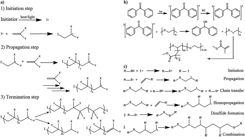 | ||
| Fig. 10 (a) Mechanism of a typical free-radical polymerization reaction initiated by light/heat (reproduced/adapted from ref. 358 with permission from The Royal Society of Chemistry358); (b) an example of the polymerization reaction involving hydrogen abstraction from PEO by the initiator and subsequent copolymerization with the MMA monomer (reproduced/adapted from ref. 359 with permission from Springer Nature, Copyright 2009359); and (c) the possible reaction pathways for the generated free-radicals during the thiol–ene click reaction (reproduced/adapted from ref. 360 with permission from John Wiley and Sons, Copyright 2010360). | ||
Another example of free-radical polymerization is by the S˙ free-radical (thiyl radical) from the thiol moiety (–SH), which can further attack the pi-electron cloud of the ‘ene’ moiety to propagate the polymerization reaction, which is also called the thiol–ene reaction.376–379 Indeed, the thiol–ene reaction can proceed even in the absence of any external initiator by simple UV or thermal irradiation.380,381 However, an initiator's addition is reported to improve the efficiency of initiation, where both type 1 and type 2 photo-initiators or even thermal initiators can be employed.372,382,383 The thiol–ene reaction facilitates the facile formation of –C–S–C– (thioether) linkages in a polymer host (Fig. 10c).360 Considering their high efficiency and relatively mild reaction conditions, photo-initiated thiol–ene reactions are more prevalent in the context of PEs. Interestingly, the thiol–ene reaction falls under the category of a click reaction as it satisfies conditions such as (i) high yield, (ii) stereospecificity, (iii) formation of safe byproducts if any, (iv) no stringent reaction conditions required, (v) readily available starting materials, and (vi) use of environmentally benign solvents or solvent-free reaction conditions.376 Other than the ‘ene’ group, epoxy groups are also suitable for thiyl radicals to carry out the click-reaction. Such reactions are called thiol–epoxy reactions.384 They are also useful in the preparation of PEs.
Although the typical free-radical polymerization method, as presented in Fig. 10a, is the most explored in the context of the in situ processing of LBs, the hydrogen abstraction and thiol–ene click reactions are also addressed in a few reports. Many mono- and bi-functional acrylate and methacrylate monomers/oligomers that are commonly used in the free-radical initiated in situ processing of PEs and LBs are presented in Fig. 11 and 12, respectively. Many of the important literature reports related to the in situ process involving free-radical polymerization are covered in Sections 5.1–5.3.
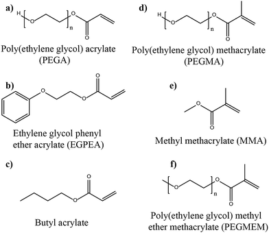 | ||
| Fig. 11 The chemical structures of mono-functionalized acrylate and methacrylate monomers and oligomers used to prepare PEs and in situ processing of LBs by the free-radical polymerization process. (a) Ref. 363 (b) ref. 364 (c) ref. 365 (d) ref. 366 (e) ref. 331, 333, 347, 367 and 368 and (f) ref. 329, 369 and 370. | ||
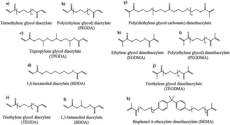 | ||
| Fig. 12 The chemical structures of mono-functionalized acrylate and methacrylate monomers and oligomers used for the preparation of PEs and in situ processing of LBs by the free-radical polymerization process. (a) Ref. 308 and 385 (b) ref. 361 and 386–389 (c) ref. 390 (d) ref. 269 and 391 (e) ref. 365 (f) ref. 392 (g) ref. 393 (h) ref. 368 (i) ref. 370, 394 and 395 (j) ref. 343 and (k) ref. 329, 342, 354 and 396. | ||
5.1 Separator assisted in situ process
One of the first reports on the in situ process for the fabrication of a GPE-based LIPB (LCO|GPE|carbon) was published by Sun et al. in 1997.397 This work introduced the concept of “monomers are reacted in place, either on a piece of thin supporting fabric or directly onto one electrode surface, just prior to cell assembly,” by a thermally-induced free-radical polymerization reaction. In other words, this work put forward the concept of both the separator assisted and direct deposition approaches. Herein, the in situ processing of the LIPB is carried out in the presence of a synthetic fabric separator considering the ease of handling, although a detailed account of the exact procedure used is not discussed. Also, the possibility of using acrylate, allyl, and vinyl ether monomers/oligomers as potential candidates to carry out the in situ process is also proposed in the same work. The prepared GPE is claimed to possess a high ionic conductivity in the order of 1 mS cm−1 at room temperature (RT), and the LIPB cell retained 80% of its initial specific capacity even after 500 cycles. Later, in the early 2000s, Kim et al. fabricated an LIPB pouch cell based on a cross-linked GPE starting from a precursor made of the oligomer named triethylene glycol dimethacrylate (TEGDMA), a plasticizer (LiPF6 in EC:DEC as the LE), and a thermal initiator (BPO), which is injected into the LCO|GPE|graphite cell assembly containing a Celgard separator followed by a heating step (80 °C for 40 min).343 The GPE exhibited high ionic conductivity (6.34 mS cm−1 at 20 °C) with an oxidative stability of 4.5 V vs. Li|Li+. The flow chart of the pouch cell fabrication by the in situ process is displayed in Fig. 13a. The cell at a current density of 0.5C showed a capacity of ≈675 mA h at 20 °C, with 100% retention over 20 charge–discharge cycles.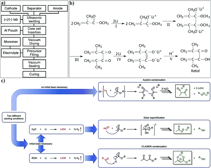 | ||
| Fig. 13 (a) Flow-chart representing the various steps involved in the in situ processing of LIPBs in a pouch cell configuration by the separator assisted approach. The two electrodes and the separator are assembled in an aluminum laminated pouch. Later, the precursor solution is filled into the assembled cell and vacuum-sealed. Thermal curing at 80 °C for 40 min results in an LIPB (reproduced/adapted from ref. 343 with permission from Elsevier, Copyright 2002343). (b) A plausible mechanism for the reduction of ester groups from methacrylate monomers leading to the formation of a ketol layer over Li-metal (reproduced/adapted from ref. 331 with permission from Springer Nature, Copyright 2004331). (c) The plausible mechanism for the decomposition of molecules containing ester groups in the proximity of Li-metal (reproduced/adapted from ref. 402 with permission from American Chemical Society, Copyright 2019402). | ||
A few of the other monomers and oligomers appearing in subsequent reports on the in situ processing of LIPBs during the first decade of the 21st century include MMA, tetraethylene glycol diacrylate, 1,3-butanediol diacrylate (BDDA), and poly(ethylene glycol) acrylate (PEGA).363,367,385,392 These reports also employed heat-induced in situ processing using organic carbonate-based solvents as plasticizers and LiPF6 salt as the Li+-ion source.392 However, it is important to note that Li-salts such as LiPF6 (thermal stability of 107 °C in a dry and inert atmosphere) have very low thermal stability and therefore require special attention.398–400 The presence of even a few ppm of water in the electrolyte can induce the conversion of PF5 (PF5 is formed by the decomposition of LiPF6 salt) to toxic gaseous products such as HF and POF3 even at RT, and the same reaction will be accelerated at elevated temperatures. These side-reaction byproducts can catalyze several other reactions such as the decomposition of other organic solvents or monomers/oligomers and even the leaching of transition metals from the electrode active materials. However, within the first few years of the 21st century, the separator assisted approach of the in situ process by thermal curing was commercialized for the production of LIPBs as already demonstrated in the case of the Sanyo process, but with a thermally stable sulfonylimide-based (LiBETI) salt (see Fig. 9).352,353,401
With the rejuvenated interest in LMPBs during the same period, in several reports, the electrochemical performance of LMPBs is often found to be inferior compared to the related LIPBs when acrylate/methacrylate functional monomers are used. For instance, the NMC111|GPE|Li cell constructed using a PEGA oligomer-based GPE displayed inferior rate-capability compared to the NMC111|GPE|graphite counterpart.363 Similarly, when MMA is used as the monomer and the performance is compared in LIPBs and LMPBs, the inferior electrochemical performance associated with LMPBs is addressed.331,367 In both LPB cells based on MMA, LiNi0.8Co0.2O2 (LNC) is used as the cathode. Here, in the case of the Li-metal anode, a large voltage-drop is observed in the first charging cycle compared to the cell with a graphite-based anode. This voltage-drop is attributed to the non-conducting polymer layer (e.g., PMMA layer) formed at the Li-metal anode during the polymerization process. This PMMA layer is claimed to disintegrate during the charging process, which can affect the Li plating/stripping process leading to the uneven deposition of Li (HSAL growth) in the subsequent cycles. Also, in the same report,367 the reduction of the ester groups from the unreacted acrylate monomers over the Li-metal surface leading to the formation of undesirable ketol products (Fig. 13b) is explained. This reduction reaction can take place even before the electrochemical cycling and can lead to capacity loss even in the first cycle itself. Interestingly, when the complete monomer to polymer conversion reaction is achieved using high energy γ-ray irradiation,331,403–405 the formation of ketol products is found to be reduced. It should also be noted that, when MMA is polymerized by thermal irradiation, an oxidative stability window of 4.2 V vs. Li|Li+ is observed, whereas it is increased to 4.5 vs. Li|Li+ in the case of more effective γ-ray irradiation. This indicates that the presence of residual (unreacted) monomers not only affects the cathodic but also the anodic processes. Even though high energy γ-ray irradiation is costly, unsafe, and uncontrolled (highly random in nature during polymerization), the above-mentioned work provides significant insights on the importance of avoiding undesirable parasitic reactions imposed by pristine monomers/oligomers on the Li-metal surface, which are often detrimental to the battery performance. Additionally, they also highlighted the importance of selecting suitable monomers/oligomers and achieving complete polymerization during the in situ process. Indeed, it is worth mentioning that the polymerization time is an important factor, as it determines the duration for which the MMA monomer molecules remain close to the reactive Li-metal surface. In the case of thermal polymerization, the time required is very long compared to γ-ray irradiation. Even though the article does not specifically mention this factor, the polymerization time could be an important parameter in controlling the surface reactions.
In recent reports, Grünbaum et al. suggest that the presence of trace impurities such as water and alcohol is the primary reason for the decomposition of the ester group in proximity with Li-metal. Also, it is demonstrated that the formation of LiOH or lithium alcoholates (LiOR) can hydrolyze ester bonds in a continuous process (ester saponification or Claisen condensation), which, as a side product, can generate more alcohol molecules as shown in Fig. 13c.402 Additionally, the native impurities such as LiOH formed on the surface of Li-metal, which is solubilized by the moisture present in the monomer, can also induce several of these side reactions. Therefore, it is crucial to make sure that ester-based monomers and oligomers are dry and extra pure when used in LMPBs to achieve the best performance. Provided that additives that can guarantee the formation of a stable SEI over Li-metal anodes or Li-metal compatible acrylate/methacrylate molecules are used in the precursor, the separator assisted approach can be much effectively revisited for LMPB fabrication,395 but preferably with a precursor free from impurities (ultra pure/battery grade). Despite the aforementioned drawbacks, PEs that are derived from acrylate and methacrylate monomer/oligomer molecules remain the most explored and popular for executing the in situ processing of LPBs due to their ease of polymerization and low cost.
The transition from non-cross-linked to cross-linked acrylate/methacrylate hosts has been found to improve the interfacial properties of PEs against the Li-metal anode. Unlike the PEs based on linear polymer hosts such as PMMA, cross-linked PEs minimize HSAL-growth. An illustration in the context of a cross-linked PE formed from the oligomer called poly(ethylene glycol) dimethacrylate (PEGDMA) is presented in Fig. 14a.394 In a multi-functional cross-linker molecule bearing acrylate/methacrylate functional groups, the spacer molecule between the terminal functional groups can be of different chemical nature. For example, the spacer group can be ethylene oxide (–EO–), polycarbonate, polyurethane, polysiloxane, etc. The spacer molecule/chain part can largely influence the physicochemical, interfacial, and electrochemical characteristics of the final cross-linked polymer network. Additionally, these spacer chains can have many or a few repeating units (RU); hence, the properties of the cross-linked polymer network can be tailor-made according to the application. For example, methacrylate oligomers having the spacer molecule poly(diethylene glycol carbonate) are used for the preparation of GPEs and SPEs for LMPB cells by employing the in situ process [Fig. 14b–d].393 A precursor made of poly(diethylene glycol carbonate) dimethacrylate (PDEC-DMA), which is a bi-functional cross-linker, other hydroxyl and ethyl terminated mono-functional methacrylic derivatives, a plasticizer (EC/DMC), a thermal initiator (AIBN), and LiTFSI salt are used for producing cross-linked GPEs. At the same time, a precursor for the SPE is prepared in the absence of a plasticizer. A cellulose separator pre-soaked in the precursor is used for the in situ processing of the LMPB cell. The GPE exhibited an ionic conductivity of 0.17 mS cm−1 (25 °C) and a TLi+ value of 0.47, which is higher than several LEs (TLi+ value of 0.2–0.3).167 The improvement in the TLi+ value is also attributed to the presence of spacers based on carbonate moieties.406 GPE- and SPE-based LMPB (LFP‖Li) cells delivered cycling stability over several hundred cycles at both 25 and 100 °C. Indeed, the good cycling stability can be attributed to the cross-linking and the cellulose reinforcing nature of these PE systems.
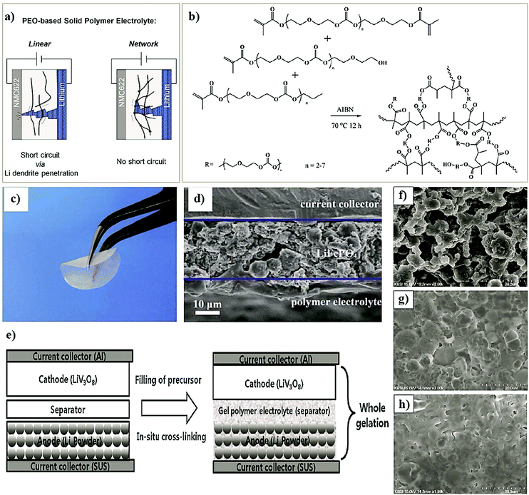 | ||
| Fig. 14 (a) Schematic representation of the mechanism by which HSAL-growth induced cell failure is prevented in a cross-linked PEO (depicted as a network)-based SPE compared to that of a linear PEO-based SPE (reproduced/adapted from ref. 394 with permission from Elsevier, Copyright 2020394). (b) Synthesis scheme for the preparation of the SPE based on methacrylate monomers derived from poly(diethylene glycol carbonate) molecules. (c) Photograph of the cellulose reinforced PE. (d) Cross-sectional view of the electrode|electrolyte interface in the LFP cathode retrieved from the LMPB cell (reproduced/adapted from ref. 393 with permission from The Royal Society of Chemistry393). (e) The in situ processing of an LMPB with a Li-powder anode and LVO cathode by the separator assisted approach. (f and g) The SEM images of the pristine (f) and cycled Li-metal anodes with a low (g) and high (h) degree of cross-links in the GPE (reproduced/adapted from ref. 395 with permission from Elsevier, Copyright 2014395). | ||
A GPE-based LMPB cell is fabricated using a heat-assisted in situ process in which a LiV3O8 (LVO) cathode is assembled with (Fig. 14e) a Li-powder-based anode.395 The cross-linked GPE is produced from a precursor containing a dimethacrylate-based oligomeric cross-linker, which bears spacer chains based on –EO– molecules (poly(ethylene glycol) dimethacrylate, PEGDMA), a plasticizer (1 M LiPF6 EC:DEC as an LE), and a thermal initiator (t-amyl peroxypivalate, TAPP). In this work, the potential of additive chemistry is explored for enhancing the overall electrochemical performance, for which a small amount of (1 wt%) vinylene carbonate (VC) is added into the precursor. In LEs, the primary role of VC is to act as an artificial SEI layer forming agent over the anode surface; in this case, it is Li-metal.407–409 Here, as the polymerization rate of methacrylate is very high and the concentration of VC in the precursor is very low, it is not expected that the VC molecule will become a part of the main chain of the polymer network. Although not explicitly mentioned, the presence of VC in this work is expected to mitigate/minimize any undesirable passivation (by dimethacrylate) over the Li-metal anode. A typical artificial PIS-SEI formed due to the presence of VC may also include species such as poly(vinylene carbonate) (poly-VC), Li2CO3, and lithium alkyl carbonates. Again, this work further emphasizes the significant relationship between the impact of cross-links and reduction in dendritic HSAL growth (as explained in Fig. 14a). Unfortunately, the powdered Li-metal anode is very reactive due to its high surface area available for reactions with the electrolyte components. The HSAL growth in the powdered Li-anode is a big challenge, and it is found to be suppressed when the cross-linking density in the GPE is further increased with a higher PEGDMA concentration in the precursor [Fig. 14f–h].57,395,410 Indeed, at higher current rates (2C), the GPE-based cell retained 85% of the discharge capacity (187 mA h g−1) compared to the value at 0.2C (220 mA h g−1). This work indicates that fine-tuning of the cross-linking density or, in other words, the toughness of the PE is crucial for achieving improved interfacial properties, hence preventing HSAL growth and ensuring good cycling performance in LMPBs.
The in situ processing of an LNMO|GPE|Li cell using a precursor consisting of a combination of a low molecular weight diacrylate cross-linker (triethylene glycol diacrylate, TEGDA), a co-monomer (butyl acrylate, BA), a plasticizer LE (1 M LiPF6 in a mixture of carbonate solvents), and a thermal initiator (2,2′-azobis-(2,4-dimethylvaleronitrile), ABVN) was reported by Fan et al.365 Here, the amount of BA (monoacrylate) used is almost double that of TEGDA in the precursor, which reduces the overall cross-linking density, rendering the finally produced cross-linked PE with enough flexibility and ease of processibility. The GPE was claimed to possess ionic conductivity (5.5 mS cm−1, 25 °C) close to that of an LE, and oxidative stability up to 5 V vs. Li|Li+. Finally, the fabricated LNMO|GPE|Li cell delivered a discharge capacity of 226 mA h g−1 between 2 V and 4.8 V (0.1C, 25 °C). Recently, a hierarchical gel-PCE, as shown in Fig. 15a, was produced by using only a bi-functional cross-linker (tri propylene glycol diacrylate, TPGDA). The resulting gel-PCE in which SiO2 hollow nanospheres are used as nanofillers is analyzed in LMPBs.390 Due to the high porosity of the nano SiO2 spheres, during the activation process, these PCEs act as an electrolyte reservoir, hence absorbing a considerable amount of LE (1 M LiPF6 in organic liquid carbonates).420 The LMPB fabrication is carried out by the in situ process; the researchers incorporated the LE (1 M LiPF6 in organic carbonates) and AIBN into the precursor followed by thermal curing at 60 °C for 12 h. The resulting SiO2-integrated gel-PCE (called SiSE) exhibited high mechanical stability owing to the cross-linked polymer host derived from TPGDA, and a good ionic conductivity value of 1.7 mS cm−1 at RT. Interestingly, the SiSE displayed dramatically low flammability due to the presence of SiO2, along with improved interfacial resistance and HSAL growth suppression at the Li-metal anode (Fig. 15b). High oxidative stability (4.9 V vs. Li|Li+) and good cycling stability in LFP|SiSE|Li cells (discharge capacity = 160 mA h g−1 at 0.2C, 200 cycles, Fig. 15c) are also achieved.
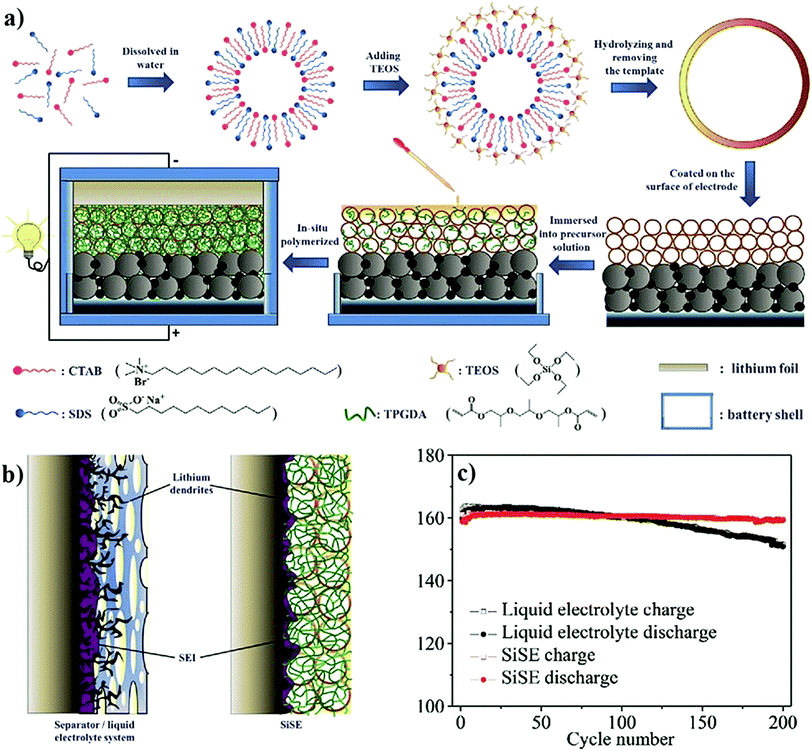 | ||
| Fig. 15 (a) Schematic illustration of the steps involved in the SiO2 templated in situ processing of LFP|SiSE|Li cells; (b) stable SEI over Li-metal in the presence of SiSE preventing HSAL growth compared to that of the poor SEI formed in the case of LEs; and (c) comparison of the cycling stability of SiSE- and LE-based LFP‖Li cells (reproduced/adapted from ref. 390 with permission from John Wiley and Sons, Copyright 2016390). | ||
Several studies use multi-functional acrylate/methacrylate monomer/oligomer molecules with ‘n’ (number of functionalities) value >2 (called poly-functional to distinguish from bi-functional molecules) that can result in cross-linked PEs [Fig. 16a–d]. Zhou et al. used a tri-acrylate cross-linker (trimethylolpropane trimethylacrylate, TMPTMA) and a thermal initiator (lauryl peroxide, LPO) in the presence of an LE (1 M LiPF6 in a mixture of carbonate solvents).412 The resulting cross-linked GPE film exhibited a high ionic conductivity (1 mS cm−1) and oxidative stability value (5.0 V vs. Li|Li+). The LIPB (fabricated by the separator assisted process) cell (LCO|GPE|graphite) exhibited an initial discharge capacity of 129 mA h g−1 at 0.2C over 100 cycles with a specific capacity retention of 83%, which underlines the potential of poly-functional monomers for the in situ processing of LPBs. Jeong et al. used a slightly different cross-linker (trimethylolpropane triacrylate, TMPTA), a non-volatile plasticizer (PEGDME, Mn = 250 Da), a thermal initiator (AIBN), and an LE (LiTFSI in PC).411 The precursor is used for LFP|GPE|Li cell fabrication using the separator assisted in situ approach. Even though the increase in cross-linking density due to the increased amount of TMPTA (15 wt%) reduced the ionic conductivity and high rate capability, the onset potential of oxidative decomposition of the GPE is increased up to 5.3 V vs. Li|Li+. In line with the studies using multi-functional cross-linker monomers/oligomers, Li et al. reported a GPE based on a tetra-acrylate cross-linker (pentaerythritol tetraacrylate, PETEA) and the final LIPB is fabricated by combining a high voltage LiNiCoAlO2 (NCA) cathode, and the separator assisted in situ process.417 The free-radical polymerization mechanism of PETEA is presented in Fig. 17a.418 The work also demonstrates the capability of the separator-supported GPE in providing enhanced safety to the LIPB cell over LEs by the nail penetration test [Fig. 17b–d]. During the safety test, the surface temperature of the LE-based LIB cell increases beyond 200 °C, whereas only to 105 °C in the LIPB, in turn resisting the hazardous combustion reaction [Fig. 17c and d]. Indeed, in the same work, it has been convincingly demonstrated by the same authors that the elastic nature of the cross-linked GPEs can suppress the volume changes occurring in Si-electrodes during repeated electrochemical cycling (in a NCA|GPE|Si cell). A general scheme representing the elastic nature of the PEs controlling the volume expansion of the Si anode is illustrated in Fig. 18a and b.421 In another study of a similar kind by Bok et al., the cross-linked homo-polymer-based GPE derived from the cross-linker ethoxylated trimethylolpropane triacrylate (ETPTA) is found to be effective in controlling the volume change of Si anodes in LIPBs.413 Here, it is claimed that the precursor blends with the silicon anode via synergistic coupling (Fig. 18c). The discharge capacity, rate capability, and cycling stability of the Si|GPE|Li half-cell with GPEs are found to be far superior to the LE-based cells. Scanning electron microscope (SEM) images evidencing the suppressed volume changes in different types of silicon anodes in the in situ processed LIPB cells are also presented in Fig. 18d–l.
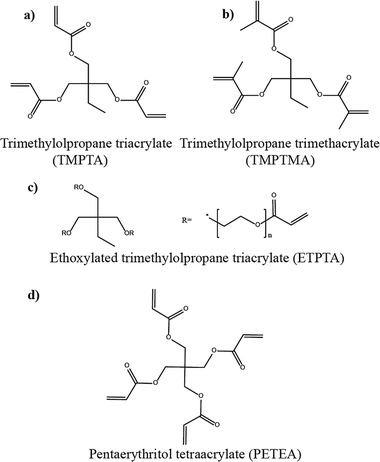 | ||
| Fig. 16 The chemical structures of poly-functional acrylate and methacrylate monomers used for the generation of PEs and fabrication of LBs by the in situ process. (a) Ref. 411 (b) ref. 412 (c) ref. 269 and 413–416 and (d) ref. 417–419. | ||
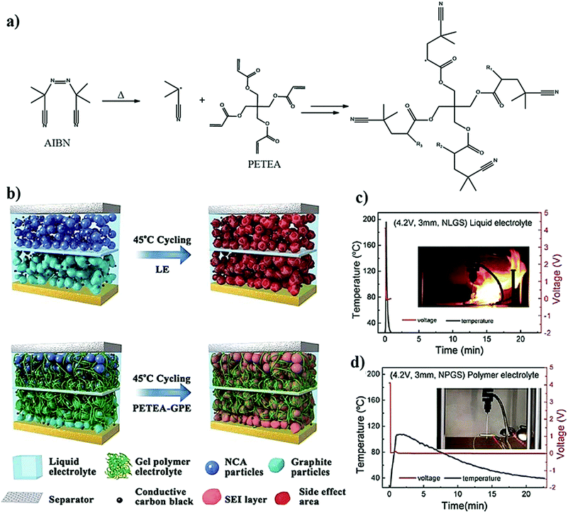 | ||
| Fig. 17 (a) The mechanism for the free-radical polymerization of PETEA to poly-PETEA (R1, R2, and R3 represent molecular chains (reproduced/adapted from ref. 418 with permission from Elsevier, Copyright 2016418). (b) The illustration of changes occurring inside the LE- and GPE-based cells (denoted as NLGS and NPGS, respectively) during cycling. In the case of LE-based cells, the interphases at the electrodes are not uniform and not effective. This leads to side reactions between the electrode and LE components, leading to early failure of the cell. However, in the case of the in situ processed GPE-based cell, the efficient interphases inhibit the side reactions and improve the cycling stability. (c) The nail penetration test results of the LE-based cell leading to inflation and violent combustion (the surface temperature increased to 200 °C). (d) The GPE-based cell exhibited no obvious changes, and the highest surface temperature reached after the nail penetration test is only 105 °C (reproduced/adapted from ref. 417 with permission from The Royal Society of Chemistry417). | ||
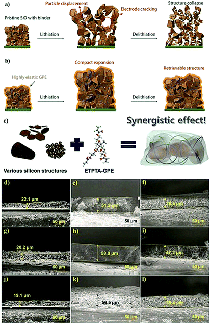 | ||
| Fig. 18 (a) Volume change, particle displacement, and cracking leading to the structural collapse of the silicon-anode during the repeated lithiation and de-lithiation process in the absence of an elastic GPE; and (b) the suppression of the afore-referenced structural collapse in the case of a silicon-anode integrated with an elastic GPE (reproduced/adapted from ref. 421 with permission from Springer Nature, Copyright 2019.421 Distributed under a Creative Commons Attribution License International 4.0 (CC BY 4.0) (https://creativecommons.org/licenses/by/4.0/)). (c) Schematic illustration of various silicon structures used as anode materials and their synergistic coupling with an ETPTA-based GPE during the in situ process; and (d–l) cross-sectional SEM images depicting the extent of volume expansion of various Si-anodes. In the 1st column (d–j), pristine anodes are shown. The 2nd and 3rd column depict the volume expansion of Si-anodes retrieved from the LE (e–k) and GPE (f–l) based cells (after 100 cycles). (d–f) mesoporous Si; (g–i) micro-sized macroporous Si; and (j–l) Si sheet (reproduced/adapted from ref. 413 with permission from The Royal Society of Chemistry413). | ||
Poly-functional acrylate-based PEs also find application in the in situ processing of advanced LMBs, in particular lithium–sulfur (S|PE|Li) batteries.418,422 In S|PE|Li battery cells, it has been proposed that cross-linked PEs can trap the polysulfides (Fig. 19a) and help in suppressing their migration to the metallic Li-anode, which in turn improves the cycling stability and Coulombic efficiency.423–425 For this purpose, a PETEA-based precursor was thermally cured to obtain cross-linked GPEs by Kang et al.418,419 During the LMPB cell preparation process, the precursor is injected into a PMMA-based electrospun fiber network, which isolates the Li-metal anode and S-cathode. The resulting GPE exhibits a high ionic conductivity of 1 mS cm−1. The S|GPE|Li cell is operated between 1.7 and 2.8 V showing a discharge capacity of 486 mA h g−1 at 5C. Indeed, the excellent cycling stability (83% capacity retention after 500 cycles at 0.3C) of the S|GPE|Li cell is attributed to the largely reduced polysulfide diffusion/shuttling imparted by the cross-linked polymer host (similar to the representation in Fig. 19a). The same group further demonstrated the use of cross-linked GPEs for the fabrication of polysulfide|GPE|Li and S|GPE|SnO2 battery cells, and improved performance due to the cross-linked nature of the PE system is confirmed.422,426
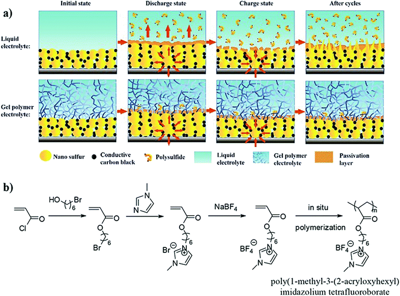 | ||
| Fig. 19 (a) The mechanism of trapping of polysulfides in a PETEA-based GPE. In the LE-based S|LE|Li battery cell, the breakdown and reconstruction of the passivation layer (CEI) due to the volume changes in the S cathode during the charge/discharge cycles lead to the dissolution of polysulfides. However, the in situ processing helps the tightly cross-linked PETEA-based GPE to cover the S electrode effectively by providing flexibility to the passivation layer against volume changes of sulfur particles. The PETEA-based GPE, in combination with a flexible passivating layer, effectively suppresses polysulfide dissolution and the gradual evolution of interfacial resistance (reproduced/adapted from ref. 418 with permission from Elsevier, Copyright 2016418). (b) Synthesis of the polymerizable ionic liquid monomer called MIT (reproduced/adapted from ref. 428 with permission from Elsevier, Copyright 2013428). | ||
Polymerizable ionic liquids427 (1-methyl-3-(2-acryloyloxyhexyl) imidazolium tetrafluoroborate, MIT, Fig. 19b) with acrylate groups have been used as long-chain monomers for the preparation of GPEs, and their evaluation in in situ processed high voltage LMPB cells (LCO|GPE|Li) is carried out.428 The polymeric ionic liquid host in the GPE is realized by the separator assisted thermal polymerization of the MIT monomer. In a typical procedure, the MIT monomer is dissolved in an LE (1 M LiBF4 in EC:DEC) in the presence of a thermal initiator (TAPP) and thermally cured (90 °C for 20 min) with the support of a separator. A small amount of fluoroethylene carbonate (FEC) is also added to the precursor as a PIS-interphase forming additive. The ionic conductivity of the GPE decreases with an increase in the percentage of the MIT monomer; however, an ionic conductivity of 1 mS cm−1 is easily achieved at RT. The in situ processed LMPB cell by the separator assisted approach displayed a discharge capacity of ≈134 mA h g−1 (25 °C) with good specific capacity retention (90%, 50 cycles, 0.2C). In a similar approach, however, using a novel PE matrix architecture such as an interpenetrated network (IPN), Huang et al. demonstrated a polymeric ionic liquid-based GPE for the separator assisted processing of LMPBs. Indeed, a porous PVdF–HFP electro-spun membrane is used as a separator for the in situ fabrication of an LMPB (LFP|IPN–GPE|Li) cell by the thermal curing process (70 °C, 12 h).429 An IPN polymer is a mixture of two or more polymer networks that are not covalently linked to each other but entangled (interlaced) in such a way that the individual polymer networks cannot be pulled apart unless chemical bonds are broken.389 In this work, along with a mono-functional ionic liquid-based long-chain acrylate monomer (1-butyl-3-(2-methacryloyloxyhexyl)imidazolium bis(trifluoromethane sulphonyl) imide, MHBIm-TFSI), a diacrylate oligomer (poly(ethylene glycol) diacrylate, PEGDA) is also used as a cross-linker to enhance the cross-linking density, which improves the overall mechanical stability of the resulting IPN–GPE. The resulting highly cross-linked IPN–GPE delivered a high ionic conductivity (1.3 mS cm−1) and a wide oxidative stability value (5 V vs. Li|Li+). The in situ processed (separator assisted) LMPB coin-cell is galvanostatically cycled at 40 °C, which displays a high specific capacity value (152 mA h g−1, 0.1C) along with good retention (94%, 100 cycles). Interestingly, a flexible LMPB pouch cell fabricated using the same approach also delivered a similar overall cycling performance.
Hetero functionalities often facilitate the fine-tuning of the chemical resistance,430 interfacial and transport properties (e.g., ionic conductivity, TLi+), and thermal properties (e.g., non-flammability and high-temperature stability) of PEs.431–436 For this purpose, in situ processable organic–inorganic hybrid monomers/oligomers are explored. In line with this, functional moieties such as siloxane, boranes, and phosphate groups are introduced into the monomer/oligomer structure.299,366,437 For example, Kim et al. used a star-shaped siloxane acrylate cross-linker for the preparation of LIPBs (LCO|GPE|graphite) by the separator assisted in situ process (Fig. 20a).437 The precursor made of siloxane acrylate, an LE (1 M LiClO4 in EC:DMC), and a thermal initiator (t-butyl peroxypivalate, TBPP) is supported on a microporous polyethylene substrate between the electrodes and subjected to thermal curing (80 °C, 20 min). The GPE with a cross-linker content of 5.0 wt% displayed a high ionic conductivity (1.3 mS cm−1) at ambient temperature along with wide oxidative stability (4.5 V vs. Li|Li+). The in situ processed LIPB cell delivered a discharge capacity of 137 mA h g−1 (0.5C) with 84% capacity retention over 100 cycles. Later, the same group used a tri-acrylate cross-linker (tris(2-(acryloyloxy) ethyl) phosphate, TAEP, Fig. 20b) to prepare a PE.438 The device fabrication followed a similar procedure except for using a phosphate-based cross-linker in place of siloxane acrylate, which demonstrated a comparatively average performing cell. Moreover, when they moved to a GPE based on a fluorinated phosphorous-based cross-linking agent named 2-(2-(1,1-difluoro-2-hydroxy ethoxy)-1,1,2,2-tetrafluoroethoxy)-2,2 difluoroethylacrylate (FTGA) (Fig. 20c), superior ionic conductivity (0.49 mS cm−1 for the TAEP-based GPE and 0.56 mS cm−1 for the FTGA-based GPE) is exhibited by the FTGA-based GPE.439 Indeed, both GPE systems exhibited a lower oxidative stability value of 4.2 V vs. Li|Li+. Thus, it can be learned that the selection of the hetero-functionality is critical for achieving improved electrochemical performances, and even though fluoro- and phosphate-based polymers deliver improved safety, their electrochemical performance needs to be further enhanced.
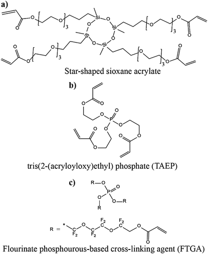 | ||
| Fig. 20 (a) Chemical structure of the siloxane functionalized acrylate monomer;437 (b) tris(2-(acryloyloxy) ethyl) phosphate;438 and (c) the fluorinated phosphorous-based cross-linking agent.439 | ||
In contrast to the earlier-mentioned reports in which a single hetero-atom functionalized cross-linker is used alone, boron-based cross-linked copolymer hosts derived from a combination of linear and branched acrylate cross-linkers have been proposed for LMPBs.366 Here, boron-containing acrylate cross-linkers are prepared by a reaction involving trimethyl borate (TMB). For instance, the bi-functional linear borate cross-linker (LBC) is synthesized from glycerol monomethacrylate (GMMA) and TMB in the presence of poly(ethylene glycol) (PEG) (Fig. 21a). On the other hand, the tri-functional branched borate cross-linker (TBC) is prepared by the reaction between poly(ethylene glycol) methacrylate (PEGMA) and TMB (Fig. 21b). Considering the combination of di- and tri-functional methacrylate cross-linkers, the PE can be considered to possess a well-balanced 3D-structure with a cross-linked and mechanically stable polymer host. The authors have convincingly demonstrated that the thermally cross-linked and flexible GPE (3D-BGPE) with a high TLi+ value of 0.76 inhibits HSAL growth compared to that of conventional LEs, as illustrated in Fig. 21c. In particular, the high TLi+ value is achieved due to the Lewis-acid character of the boron center, which interacts with the anions facilitating the free-movement of Li+-ions within the polymer matrix. Besides, the boron-containing 3D-GPE with a high TLi+ value can maintain uniform Li+-ion flex at the Li-metal|electrolyte interface, favoring the smooth deposition of Li, which is not possible to achieve with a conventional LE.440 It is worth mentioning that the 3D-BGPE exhibits a good ionic conductivity (0.084 mS cm−1, 30 °C) and an overall oxidative stability (4.5 V vs. Li|Li+). The LFP|3D-GPE|Li cell fabricated using the in situ process in the presence of a cellulose-based separator retains ≈90% of the initial capacity (118 mA h g−1, 0.5C) over 400 cycles at 30 °C (Fig. 21d). Indeed, this work is an excellent example of using an inorganic polymer matrix having a boron atom, which plays the part of a copolymer chain and a Lewis acid center to deliver high TLi+ values. However, such studies focusing on heteroatoms are scarce in the literature and must be explored further.
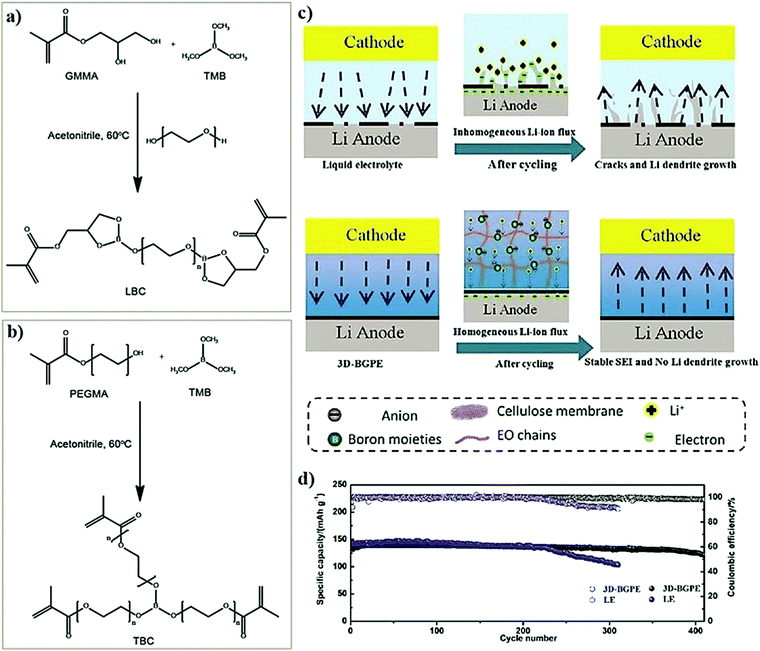 | ||
| Fig. 21 Synthesis route to (a) di- and (b) tri-methacrylate cross-linker monomers containing boron; (c) the illustration of the homogenous Li+-ion flux offered by boron-containing PEs with a high TLi+ value facilitating HSAL-free cycling in Li-metal cells compared to conventional LEs; and (d) improved cycling stability of the LFP|3D-GPE|Li cell over the LE counterpart (reproduced/adapted from ref. 366 with permission from The Royal Society of Chemistry366). | ||
In line with acrylate/methacrylate monomers and oligomers being explored for more than two decades, non-acrylate/methacrylate molecules are recently receiving attention in the context of the in situ process. For example, the monomer vinylene carbonate (VC) is often used as a popular additive in LEs for improving the properties of the PIS-SEI formed on both graphite and Li-metal anodes.441,442 Since VC contains an unsaturated double bond, it is possible to polymerize VC to poly-VC homo-polymer-based PEs by the free-radical polymerization process. One such approach was attempted by Chai et al. (Fig. 22a)443 in which an SPE-based LMPB (LCO|SPE|Li) cell is in situ processed using a thermal polymerization process. A precursor containing 1.0 M lithium difluoro(oxalato) borate (LiDFOB) in VC and an AIBN initiator is injected into a 2032-coin cell with a cellulose separator and subjected to thermal curing (Fig. 22b). However, the complete conversion of the monomer to the polymer required about 24 h. The time taken for the polymerization is very high compared to acrylates and methacrylates, which undergo polymerization faster during the thermal and UV curing process. Indeed, the UV curing process may take a few seconds to minutes for acrylates and methacrylates, whereas thermal curing takes a few minutes to hours. The poly-VC-based SPE exhibits an ionic conductivity of 0.01 mS cm−1 at 25 °C. The SPE also showed a TLi+ value of 0.57 and an oxidative stability value of 4.5 V vs. Li|Li+. At 50 °C, the separator (cellulose paper) assisted in situ processed LCO|SPE|Li cell displayed a discharge capacity of 146 mA h g−1 (0.1C), and after 150 cycles, 84% of the total initial capacity is retained. The photograph of the post-cycled PE-integrated cathode is displayed in Fig. 22c along with the cross-sectional SEM image of the cathode|electrolyte interface (Fig. 22d) of the PE-covered surface of the LCO electrode and a pristine LCO surface (Fig. 22e). The results obtained by Chai et al. are promising for VC to be further explored for PE applications as a PEO-free alternative for LMPBs.
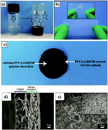 | ||
| Fig. 22 (a) The photograph presenting the conversion of VC into poly-VC followed by heating at 60 °C for 24 h; (b) photograph of the cellulose reinforced poly-VC-based SPE (denoted as cellulose/PVCA–LiDFOB); (c) photograph of the SPE-deposited LCO cathode after electrochemical cycling; (d) cross-sectional SEM image presenting the cathode|electrolyte interface; and (e) SEM image of the LCO surface before (inset) and after SPE deposition (reproduced/adapted from ref. 443 with permission from John Wiley and Sons, Copyright 2016.443 Distributed under a Creative Commons Attribution License International 4.0 (CC BY 4.0) (https://creativecommons.org/licenses/by/4.0/). | ||
Another study by the same group extended the poly-VC-based PE for the in situ processing of LIPBs as well, in which, along with the precursor solution containing VC and AIBN, an LE (1 M LiDFOB in EC:DEC) is also introduced to obtain a GPE.444 Compared to the SPE, the GPE exhibited a high ionic conductivity of 0.56 mS cm−1 and an overall oxidative stability of 4.8 V vs. Li|Li+ despite the low TLi+ of 0.34. Indeed, from a mechanical characteristic point of view, even though it is a GPE, the rigid cyclic carbonate moieties in the polymer backbone provide excellent mechanical stability. The GPE is used for the fabrication of LiFe0.2Mn0.8PO4 (LFMP)|GPE|graphite cells by the separator assisted in situ process in both the 2032-coin and pouch cell configurations. At 1C, the coin-cell delivered a discharge capacity of 120 mA h g−1 with a capacity retention of 88.7% even after 1000 cycles with a Coulombic efficiency of 100%. Ultimately, these unconventional polymer hosts other than the classical PEO or acrylates/methacrylates are also promising for PE applications concerning high TLi+, oxidative stability, and mechanical properties. Therefore, such PEs must be investigated further.
5.2 In situ processing by the direct deposition approach
In this section, the reports on the in situ processing of LPB cells using the direct deposition approach are emphasized. In this approach, cross-linked polymer hosts are considered as the most promising candidates due to their excellent mechanical properties compared to linear polymer hosts. Many of the cross-linked PEs discussed in the context of the separator assisted in situ process may be useful for the direct deposition approach as well. The transition from the separator assisted approach to direct deposition is helpful in the context of LMPBs since those precursors contain Li-metal incompatible acrylate/methacrylate or any other reactive molecules. These precursors do not come in direct contact with Li-metal, since the PE deposition is often carried out at the cathode side as shown in the direct deposition approach 1 (Fig. 8b). Hence, the unwanted side-reactions (if any) between the reactive Li-metal surface and the pristine monomers/oligomers can be avoided (Section 5.1, Fig. 13b and c).One report in which the direct deposition approach is employed for the in situ processing of LMPB cells by Niu et al. uses a mono-functional monomer called ethylene glycol phenyl ether acrylate (EGPEA).364 This work is important as it overrules the two conventional schools of thought existing in the LB community based on the existing literature reports that (i) acrylate/methacrylate monomers are not suitable for LMPBs, and (ii) cross-linked PEs are indeed necessary to prevent HSAL growth, by convincingly proving that Li-metal compatible acrylate monomer-derived non-cross-linked homo-polymer hosts with high mechanical stability are also suitable for LMPBs. Interestingly, the non-cross-linked homo-polymer-based GPE derived from EGPEA exhibits good mechanical strength, which could be due to the bulky phenyl group present in the monomer structure. A similar acrylate monomer with a phenyl group in its chemical structure called 2-hydroxy-3-phenoxypropyl acrylate (HPA) was previously used for the in situ processing of nonaqueous GPE-based supercapacitors providing high mechanical stability compared to the phenyl-free MMA counterpart.326 It is worth mentioning that the work by Niu et al. is one of those rare reports in which a non-cross-linked acrylate-based homo-polymer host is employed for the in situ processing of LMPBs by the direct deposition approach over the Li-metal anode. The work claims that, during the in situ polymerization process, the solvent molecules, the oligomeric EGPEA, and the PEGPEA fragment are firmly bound to the Li-metal surface to constitute the PIS-SEI layer. Indeed, the Li-metal body is protected against any volume changes by the synergistic combination of the PIS-SEI layer and the subsequent bulk GPE present above it. Moreover the PIS-SEI and GPE layers can suppress HSAL growth as compared to an LE or any other commonly used non-cross-linked PEs derived from monomers such as MMA. The EGPEA-based GPE exhibited an RT ionic conductivity of 3.35 mS cm−1 with an oxidative stability value beyond 4.9 V vs. Li|Li+. The as-fabricated LiNi0.5Mn0.3Co0.2O2 (NMC532)|GPE|Li cell can be operated between 2.8 and 4.6 V at RT. At 0.2C, the LMPB cell displayed a discharge capacity of 150 mA h g−1, with 98% retention over 70 cycles.
Nair et al. reported a Li+-ion conducting semi-interpenetrated (s-IPN) SPE and an innovative water-based spray deposition process of a PE coating over the cathode surface.342 Unlike an IPN, an s-IPN is a polymer blend in which the constituent individual polymer networks may be separated without disrupting a chemical bond.389 By using such a polymer matrix architecture, the benefits of multiple polymer hosts can be effectively utilized. For example, the Tg value, mechanical properties, crystallinity, and chemical sensitivity can be fine-tuned. The s-IPN-SPE is produced from a precursor solution containing an oligomeric cross-linker, namely bisphenol A ethoxylate dimethacrylate (BEMA, denoted as BDM in this work), PEO, LiTFSI salt, AIBN, and acetonitrile solvent as a processing aid. The optimized SPE displayed an ionic conductivity in the order of 0.01 mS cm−1 at 20 °C which exceeded 1.0 mS cm−1 at 80 °C with an oxidative stability value of 4.5 V vs. Li|Li+. For the fabrication of LMPBs (LFP|SPE|Li) in a pouch bag configuration by the in situ process, the precursor (water as a solvent and 2,2′-azo bis(2-methylpropionamidine) dihydrochloride (AAPH) as the initiator) is spray-coated over the cathode surface followed by a thermal curing process. The formed SPE-integrated composite electrode is then dried under a vacuum at 90 °C for the complete removal of water. At 70 °C, the LMPB cell delivered a discharge capacity of 160 mA h g−1 at 0.1C. Surprisingly, at 1C, a capacity value of 140 mA h g−1 is obtained, and 70% of it is retained even after prolonged 2000 cycles. In another report, a GPE based on BEMA combined with a high boiling point organic plasticizer, namely dimethyl polyethylene glycol (DPG) and LiTFSI salt, is reported (Fig. 23a).396 This approach is a solvent-free in situ processing technique and carried out using a thermal curing process (AIBN, 80 °C for 1.0 h.) Compared to SPEs based on BEMA and PEO, the GPE system exhibited high ionic conductivity values of 0.10, 0.14, and 1.4 mS cm−1 at 0, 20, and 100 °C, respectively. This proves that better plasticization is induced by DPG as compared to long chain and high molecular weight PEO. Additionally, the TLi+ values achieved for DPG-based GPEs are also superior to those of PEO-based SPEs. It is worth noting that this process is a solvent-free technique, less tedious, and faster than solvent-based processing. Finally, the GPE is stable beyond 4.7 V vs. Li|Li+, and a TLi+ of 0.45 at 25 °C is also obtained. The cathode–electrolyte composite electrode is then contacted with a Li-metal anode, and the LMPB cell is fabricated. The in situ processed LFP|GPE|Li (LFP modified with PEDOT:PSS) cell displayed a discharge capacity of 130 and 140 mA h g−1 (at 0.1C) when cycled at 25 and 70 °C, respectively. In both cases, it is also cycled for more than 300 cycles without any failure. These two reports are engaging in the context of a direct deposition approach as they use a single bi-functional cross-linker BEMA in the precursor solution, and both solvent-induced and solvent-free processing approaches are proposed along with a spray deposition method and an s-IPN polymer host architecture.
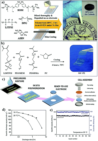 | ||
| Fig. 23 (a) Materials and processes involved in synthesizing a BEMA-based GPE and the in situ processing of the PE over an LFP electrode. On the right-hand side, the physical appearance of the self-standing GPE film is given. The inset presents the ready-to-use PE deposited LFP electrode for LMPB fabrication (reproduced/adapted from ref. 396 with permission from Elsevier, Copyright 2016396). (b) Components in the precursor and scheme adopted for the synthesis of the SIC-PE film; (c) schematic representation of the in situ processing of LFP|SIC-PE|Li cells by the direct deposition approach; (d) specific capacity as a function of C-rate at 25 and 70 °C; and (e) plot of the cycling stability of the LFP|SIC-PE|Li cell at 25 °C (reproduced/adapted from ref. 370 with permission from American Chemical Society, Copyright 2016370). | ||
Gerbaldi et al. reported an RTIL-based cross-linked IGPE by the UV irradiation process (10 min).329,369 The precursor consists of di- and mono-methacrylate oligomers, namely BEMA and poly(ethylene glycol) methyl ether methacrylate (PEGMEM), respectively. HMPP is used as the UV initiator and the RTIL (N-methoxyethyl-N-methylpyrrolidinium bis(trifluoromethanesulfonyl)imide, PY1201-TFSI-RTIL) as the liquid plasticizer along with LiTFSI salt. The optimized IGPE exhibited an ionic conductivity of 0.80 and 5.5 mS cm−1 at 20 and 80 °C, respectively. Here, the copolymer host can be considered as a loosely cross-linked copolymer due to the combination of di- and mono-methacrylate oligomers present in the precursor, which results in a low cross-linking density. Additionally, the pendant chain of PEGMEM can act as an internal plasticizer to reduce Tg and increase the Li+-ion transport. Due to the presence of the RTIL, which is thermally stable at high temperature, the overall thermal stability of the IGPE is beyond 300 °C, and a high oxidative stability value of 5.2 V vs. Li|Li+ is also achieved. High thermal stability is inherited from the high boiling point of the RTIL used, which cannot be achieved using conventional carbonate-based solvents. However, the TLi+ value is found to be as low as 0.18 at 60 °C, which is a typical challenge concerning the use of RTILs, where the high concentration of mobile ions imparts a high total ionic conductivity (coming from the conductivity of the anion and cation), but limited Li+-ion conductivity (σLi+). Indeed, for application in LMPBs, in general, PEs should possess a very high σLi+ and the total conductivity is not quite sufficient. Still, the in situ processed LFP|IGPE|Li cell demonstrated a discharge capacity of 85 mA h g−1 (0.1C) at RT, good cycling stability, and capacity retention up to 30 cycles.
In another report from the same group, a similar precursor is used to fabricate LIPBs and LMPBs using a thin-film of V2O5 as the cathode.354 This approach is close to the one used for silicon anodes, where the volume expansion is controlled by the use of a strong network forming polymer matrix [Fig. 18a and b]. Nanomaterials such as V2O5, when exposed to long-term cycling, undergo pulverization, where these particles break into smaller particles and eventually degrade the cell. Indeed, in this work, the authors demonstrated that the in situ polymerized GPE could hold the nanoparticles tight and avoid pulverization; hence long-term cycling can be achieved. The LMPB cell displayed a discharge capacity of 130 mA h g−1 at a current rate of 1.5C. After cycling for 500 cycles at various current rates, a 70 mA h g−1 specific capacity is still retained at 10C. Besides, in the LIPB cell (graphite anode), the specific capacity is found to be around 100 mA h g−1 (1C) and 75 mA h g−1 (5C) after 50 cycles.
In another study from a different group, using a similar approach, a cross-linked IGPE is prepared from a combination of tri- and di-acrylate cross-linkers, and an RTIL/lithium salt mixture (Pyr13-TFSI/1 M LiTFSI) in the presence of HMPP.269 It is observed that the RT ionic conductivity is a maximum for the IGPE derived from the short-chain cross-linkers ETPTA and 1,6-hexanediol diacrylate (HDDA) (1.1 mS cm−1). The in situ processed LMPB cell (LFP|IGPE|Li) exhibited a specific capacity of 120 mA h g−1 (0.2C and 20 °C), and was stable over 50 cycles. Apart from the thermal stability offered to the PE by the RTIL, this work also suggests the suitability of cross-linked IGPEs in offering better Li-plating morphologies than carbonate solvents in GPEs. Hence, it can be learned that RTILs combined with suitable cross-linked polymer hosts can convincingly reduce the pulverization of electrode materials, offer high thermal and oxidative stability, and improve the Li-deposition morphologies in LMPBs.
Single-ion conducting polymer electrolytes (SIC-PEs) are those in which the anion is covalently attached to a polymer chain so that the ion conduction occurs exclusively due to the mobility of cations (or vice versa). Such Li+-ion conducting SIC-PEs can offer remarkably high TLi+ values, which can help suppress HSAL growth by maintaining a uniform flux of Li+-ions close to the Li-metal surface.446–449 It is a challenging task to achieve a PE that simultaneously possesses high TLi+ and ionic conductivity values.450 In a recent report, an SIC-PE possessing the aforementioned features was developed and used for LMPB fabrication by the in situ process (Fig. 23b).370 The new SIC-PE is prepared by facile and single-step free-radical copolymerization of lithium 1-[3-(methacryloyloxy)-propyl sulfonyl]-1-(trifluoromethylsulfonyl) imide (LiMTFSI) with mono- and bi-functional methacrylate oligomers, namely PEGMEM and PEGDMA, respectively. Besides, PC is used as a plasticizer to enhance the ionic conductivity. The optimized SIC-PE exhibited a high ionic conductivity of 0.11 mS cm−1 along with a high oxidative stability value of 5.5 V vs. Li|Li+ at 25 °C. The single-ion conduction in the PE is attributed to the anionic character of the loosely cross-linked copolymer-host due to the covalent tethering of the MTFSI− moieties in the polymer backbone. As a result, the only mobile species present in the PE are Li+-ions, which eventually act as the predominant charge carrier. Hence, high TLi+ values of 0.88 and 0.90 are achieved at 25 and 70 °C, respectively. Besides, in synergy with PC, the SIC-PE membranes also demonstrate excellent interface/interphase stability against the Li-metal anode. The fabrication of an LMPB cell (LFP|SIC-PE|Li) by the in situ direct deposition process is presented in Fig. 23c. A high LFP mass loading of 5 mg cm−2 is used for the cell assembly, which exhibited high cycling performance both under high (143 mA h g−1, 0.1C, 70 °C) and low (126 mA h g−1, 0.1C, 25 °C) temperature conditions (Fig. 23d). Indeed, the in situ processed LMPB cell at RT retained 98% of its initial capacity even after 100 cycles at 0.1C.
Apart from ester-containing acrylate and methacrylate vinyl monomers and oligomers, acrylate/methacrylate-free allyl species are also employed for the in situ processing of LPBs by the free-radical polymerization pathway. However, such reports are rare due to the relatively slow-polymerization of allyl monomers and oligomers.451 The slow polymerization rate of allyl molecules is mainly arising from the high stability of allyl free-radicals, which results in the inhibition of the propagating chain. The stabilization of allyl radicals is known as ‘degradative chain transfer,’ which involves the abstraction of allylic hydrogen and resonance stabilization, as shown in Fig. 24a.454 Consequently, allyl monomers and oligomers lead to the formation of low molecular weight polymers and often require large quantities of free-radical initiator species to achieve the complete conversion of the monomer to the polymer. Brandall et al. used allyl ether-terminated polycarbonate oligomers for the in situ fabrication of thin-film LMPB cells by the UV polymerization technique.445 The mono-functional allyl ether monomer (2-allyloxymethyl-2-ethyltrimethylene carbonate, AEC) is prepared by the ring-closing reaction of trimethylolpropane mono-allyl ether in the presence of 1,1-carbonyldiimidazole (CDI) (Fig. 24b). The AEC monomer is then partially homo-polymerized using 1,8-diazabicyclo[5.4.0]undec-7-ene (DBU) as an organocatalyst, and benzyl alcohol as a protic initiator. The low molecular weight PAEC oligomer formed is later mixed with LiTFSI and a photo-initiator (2,2-dimethoxy-2-phenylacetophenone, DMPA), and subjected to another round of UV irradiation to get a mechanically stable and self-standing SPE. The SPE films displayed ionic conductivities of 0.0004 mS cm−1 and 0.005 mS cm−1 at 25 °C and 60 °C, respectively, which are comparatively lower than the classical PEO–LiTFSI system. However, the SPE is directly prepared over the V2O5 electrode to obtain a V2O5|SPE|Li cell and galvanostatically cycled at 60 °C (Fig. 24c). Indeed, the cells are made from Li-metal and V2O5 thin films as the anode and cathode, respectively, which are mainly intended to be used in thin-film microbatteries. Hence, the lower conductivity may not be that detrimental as compared to a standard conventional LMPB cell.
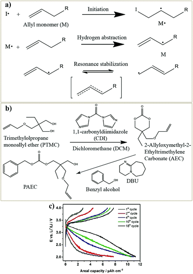 | ||
| Fig. 24 (a) The process of allyl radical resonance stabilization by a degradative chain transfer mechanism.454 (b) Synthesis of allyl ether monomer AEC and its conversion to PAEC. The PAEC is made into a precursor in the presence of a LiTFSI salt and DMPA initiator and is subjected to UV irradiation over a V2O5 cathode (direct deposition) for the in situ processing of LMPBs. (c) Galvanostatic charge–discharge profile of the V2O5|SPE|Li cell as a function of cycle number at 60 °C (reproduced/adapted from ref. 445 with permission from John Wiley and Sons, Copyright 2016445). | ||
As already explained in Fig. 10b, one way to achieve an ester-free cross-linked PE starting from linear homo-polymers such as PEO is by the generation of free-radicals by the hydrogen abstraction process. In such an approach, Porcarelli et al. used a precursor made using PEO, tetraglyme, LiTFSI, and a UV initiator (4-methyl benzophenone, MBP) (see Fig. 25a).375 Indeed, the cross-linking process is initiated through the abstraction of hydrogen from PEO; in other words, it is a protic mechanism (Norrish type II) generating a free-radical.455 This free-radical later reacts with another free-radical in the same or another –EO– chain. Tetraglyme can also be a part of the polymer chain since it also possesses hydrogen that can be abstracted like PEO. Additionally, it is reported that several oligomers of tetraglymes can be formed in cross-linked PEs, providing an additional plasticization effect. The structure of the polymer host can be considered as linear chains of PEO, cross-linked to each other, which are tethered with covalently linked tetraglyme units. One of the advantages of such an approach is that the physical properties of the polymer chain, such as crystallinity, can be controlled by the cross-linking process as the interlinking restricts the mobility of polymer chains to pack into their crystalline form. All the cross-linked PE samples exhibited ionic conductivities beyond 0.1 mS cm−1 at 25 °C. A maximum TLi+ value of 0.55 is achieved for the optimized sample along with a high oxidative stability value that goes beyond 5 V vs. Li|Li+. In Fig. 25b, the SEM image of the cross-linked PE-integrated TiO2 electrode is shown. The in situ processed TiO2|PE|Li cell exhibited a discharge capacity of ≈140 mA h g−1 at 0.1 mA cm−2 over 100 continuous cycles (20 °C) [Fig. 25c]. In another study, a similar approach was attempted by the same group, but, instead of tetraglyme, an RTIL is used.455 The mobile RTIL in the cross-linked PEO host can induce effective plasticization, which is also reflected in the improved ionic conductivity value of the IGPE (0.25 mS cm−1, 20 °C). Additionally, the cross-linking process aids in reducing or even altogether avoiding the leakage of the RTIL from the PE along with improved elasticity. Indeed, the in situ processed LFP|IGPE|Li cell cycled at both 20 and 50 °C demonstrated a high rate capability and an excellent Coulombic efficiency.
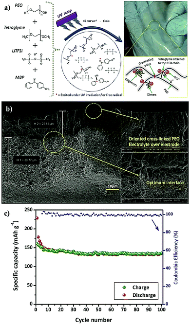 | ||
| Fig. 25 (a) Representation of the UV-light induced cross-linking process of PEO and tetraglyme by a Norrish type II pathway for the preparation of a PE. A plausible illustration of interconnected PEO chains is provided at the bottom, and the mechanically stable SPE film is shown at the top right-hand side. (b) SEM image of the electrode|electrolyte interface. (c) The complete cycling stability data of the in situ processed (direct deposition approach) TiO2|SPE|Li cell (reproduced/adapted from ref. 375 with permission from Springer Nature, Copyright 2016.375 Distributed under a Creative Commons Attribution License International 4.0 (CC BY 4.0) (https://creativecommons.org/licenses/by/4.0/)). | ||
Large size bipolar-stacked LMPBs are very important for high-voltage and high-energy applications. In line with improving the electrode|electrolyte interface in such designs, Wei et al.388 adopted the in situ polymerization process for the preparation of an SPE and cell fabrication by a thiol–ene click reaction.340,377,452,456,457 For this purpose, they employed materials such as the PEGDA oligomer, a multi-functional thiol (pentaerythritol tetra (3-mercaptopropionate), PETMP), DMPA initiator, and LiTFSI salt (Fig. 26a). The precursor prepared using the above materials is directly deposited over the LFP cathode and UV-cured to produce a PE integrated composite electrode, followed by LMPB fabrication (Fig. 26b). The molecular weight of the PEGDA and the EO![[thin space (1/6-em)]](https://www.rsc.org/images/entities/char_2009.gif) :
:![[thin space (1/6-em)]](https://www.rsc.org/images/entities/char_2009.gif) Li ratio are found to influence the ionic conductivity of the SPEs. The PEGDA (Mw = 1000 Da)-based SPE with EO
Li ratio are found to influence the ionic conductivity of the SPEs. The PEGDA (Mw = 1000 Da)-based SPE with EO![[thin space (1/6-em)]](https://www.rsc.org/images/entities/char_2009.gif) :
:![[thin space (1/6-em)]](https://www.rsc.org/images/entities/char_2009.gif) Li = 20
Li = 20![[thin space (1/6-em)]](https://www.rsc.org/images/entities/char_2009.gif) :
:![[thin space (1/6-em)]](https://www.rsc.org/images/entities/char_2009.gif) 1 displayed the highest ionic conductivity (0.13 mS cm−1, 60 °C). The high molecular weight of PEGDA can induce longer and more flexible chains between the chemical junctions in the SPE network, which provides better internal plasticization and chain mobility, thus facilitating ion conduction. Additionally, by using a long cross-linker, the cross-linking density can also be controlled. The oxidative stability value of SPE-1000 is ≈5.1 V vs. Li|Li+ with excellent thermal stability. Another report by Grewal et al. also suggests the suitability of using click reactions as a tool for producing cross-linked SPEs.452 Here, along with thiol–ene chemistry, a thiol–epoxy click reaction is also demonstrated as an efficient tool for SPE preparation (Fig. 26c). Although the in situ processing of the LPB cell is not attempted in this work, thiol–epoxy click chemistry is also expected to gain attention in the near future, which gives enough maneuverability to the production of various types of PEs.
1 displayed the highest ionic conductivity (0.13 mS cm−1, 60 °C). The high molecular weight of PEGDA can induce longer and more flexible chains between the chemical junctions in the SPE network, which provides better internal plasticization and chain mobility, thus facilitating ion conduction. Additionally, by using a long cross-linker, the cross-linking density can also be controlled. The oxidative stability value of SPE-1000 is ≈5.1 V vs. Li|Li+ with excellent thermal stability. Another report by Grewal et al. also suggests the suitability of using click reactions as a tool for producing cross-linked SPEs.452 Here, along with thiol–ene chemistry, a thiol–epoxy click reaction is also demonstrated as an efficient tool for SPE preparation (Fig. 26c). Although the in situ processing of the LPB cell is not attempted in this work, thiol–epoxy click chemistry is also expected to gain attention in the near future, which gives enough maneuverability to the production of various types of PEs.
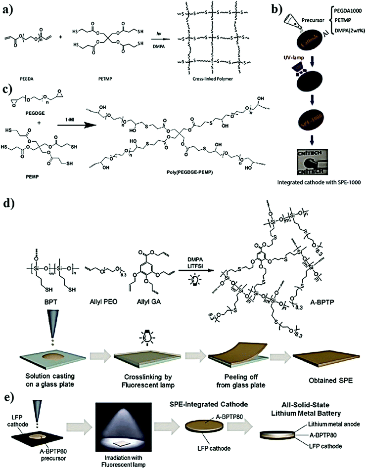 | ||
| Fig. 26 (a) The synthetic route towards the preparation of a cross-linked polymer network by a UV-light induced thiol–ene click reaction; (b) the schematic representation of the in situ processing of the LMPB cell by the direct deposition approach using an SPE prepared by a thiol–ene click reaction (reproduced/adapted from ref. 388 with permission from Elsevier, Copyright 2018388); (c) an example of a thiol–epoxy click reaction (reproduced/adapted from ref. 452 with permission from John Wiley and Sons, Copyright 2019452); (d) the formation of a cross-linked SPE by a fluorescent lamp irradiation-induced thiol–ene click reaction from allyl ether and thiol monomers (the SPE film preparation by the ex situ process is also displayed); and (e) the in situ processing of LMPBs by a thiol–ene click reaction-assisted direct deposition approach (reproduced/adapted from ref. 453 with permission from Elsevier, Copyright 2017453). | ||
Apart from the ‘ene’ group from acrylates/methacrylates, allyl ether monomers are also employed for thiol–ene click reactions. Shim et al. reported the synthesis of an SPE by a thiol–ene click reaction under fluorescent light irradiation (Fig. 26d).453 An allyl-PEO oligomer, an allyl gallic acid (n = 3) monomer, and a branched polysiloxane oligomer having a thiol group (BPT) are used for the generation of a cross-linked polymer backbone. LiTFSI and DMPA are used as a conducting salt and photo-initiator, respectively. The optimized SPE (A-BPTP80) displayed an ionic conductivity of 0.4 mS cm−1 at 60 °C. The precursor is directly deposited on an LFP cathode followed by a cross-linking reaction induced by irradiation with a fluorescent lamp for the in situ processing of the LMPB (LFP|A-BPTP80|Li) cell (Fig. 26e). The disadvantage of the fluorescent lamp is that the intensity of photons in the UV range will be significantly less so that the polymerization rate will be low, which demands irradiation for a long duration (16 h) for SPE formation. However, the final in situ processed LMPB cell displayed a discharge capacity of 150 mA h g−1 (0.1C) with a capacity retention of 88% after 50 cycles.
5.3 In situ processing of the PIS-interphase layers
A phosphate-based tri-functional cross-linker TAEP is also used to prepare a cross-linked surface protection layer over NMC111 cathode particles.460 The LE can plasticize the polymer film so that it can act as a PIS-CEI. In the LE-based LIB cell, such a protection layer can save the active cathode materials from the violent attacks of the LE. Here, the polymer-coated LIB cell retains 84% of the initial discharge capacity (180 mA h g−1 at 1C) over 50 cycles. However, the unprotected NMC111-based LIB cell retained only 74% of its initial specific capacity after the same number of cycles. In several other studies by various research groups, different polymers are used for the preparation of artificial PIS-interphases. The possibility of adopting a polyacrylate-based surface coating over a high-voltage LCO cathode was demonstrated by Lee et al. [see Fig. 27a and b].386 In this report, the precursor containing ethylene glycol diacrylate (EGDA) and HMPP is deposited over the LCO cathode. On UV curing, the LCO surface is covered by a thin layer of a cross-linked PEGDA network (20 nm). This polymer integrated electrode is then used for the fabrication of an LIB coin cell. During the cell assembly, the LE (1 M LiPF6 in EC:DMC) activates the PEGDA surface coating so that it transforms into a PIS-CEI. The cycling performance of the cell is investigated (3–4.4 V), and the assembled LIB cell delivers a first-cycle specific capacity of 150 mA h g−1 (0.5C), which is equal to that of a pristine LCO cathode-based cell. However, the specific capacity retention after several cycles is found to be higher for the LIB cell with a PIS-CEI coating compared to the uncoated counterpart (Fig. 27c). Indeed, the EIS data of the cells confirmed that the ultrathin artificial PIS-CEI remarkably reduced the impedance of the cell during long-term galvanostatic cycling as compared to the PIS-CEI-free cell. It is worth mentioning that the direct contact of LEs with pristine LCO-based cathodes leads to the formation of a highly resistive interphase layer,461 which during long-term cycling hinders the charge transfer between LCO and the LE, leading to inferior cycling characteristics (low capacity retention, low Coulombic efficiency, etc.). However, these intricacies are avoided by using the PIS-CEI layer so that this work can be considered as an excellent example of an artificially tailored PIS-CEI for LIBs.
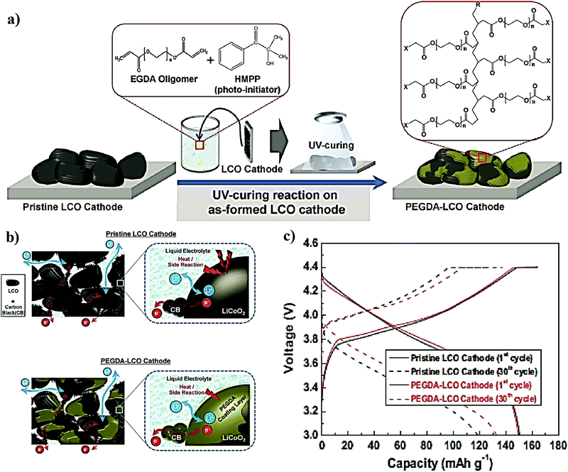 | ||
| Fig. 27 (a) Schematic illustration of the production of a PEGDA-based PIS-CEI coating over an LCO cathode from the EGDA oligomer by the UV-light assisted in situ polymerization process; (b) schematic representation of the PIS-CEI layer over the LCO cathode reducing the heat generation and side-reactions compared to the pristine-LCO cathode in the LE-based LIB cell; and (c) voltage vs. capacity plot showing the performance of pristine-LCO and PIS-CEI coated LIB cells (reproduced/adapted from ref. 386 with permission from Elsevier, Copyright 2013386). | ||
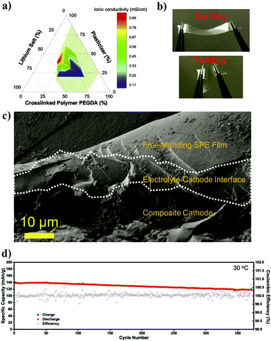 | ||
| Fig. 28 (a) Ternary phase diagram representing the ionic conductivity (measured at 20 °C) of the SPE (or PCPE) as a function of the contents of individual components in the precursor solution at 20 °C. The shadow area in the phase diagram represents the composition at which the prominent isotropic phase can be achieved in the SPE. (b) Illustration of the dimensional and mechanical stability of the optimized SPE film under bending and twisting conditions. (c) Cross-sectional SEM image of the multi-layer electrode–electrolyte assembly showing the individual layers of the cathode (composite cathode), in situ processed PIS (electrode–cathode interface), and SPE film (free-standing SPE film). (d) Cycling stability plot of the assembled LFP|SPE|Li cell at 30 °C and 0.2C (reproduced/adapted from ref. 361 with permission from Elsevier, Copyright 2018361). | ||
The isotropic phase imparts an amorphous character to the mixture, which is beneficial for increasing the ionic conductivity, and one such mechanically stable self-standing SPE film is displayed in Fig. 28b. The phase diagram approach is systematic as it can fine-tune the properties of the PE, unlike the conventional trial and error method. The precursor is made of a PEGDA oligomer, glutaronitrile (GN), LiTFSI, lithium bis(oxalato)borate (LiBOB), and a photo-initiator [bis(2,4,6-trimethylbenzoyl)-phenylphosphineoxide]. Using this formulation and process, a cross-linked PE is produced that exhibits a superior ionic conductivity of 1.0 mS cm−1 (30 °C). Here, GN is a plastic crystal, which can improve the ionic conductivity owing to its high polarity (dielectric constant, ε = 37).462 Indeed, such PEs are often called plastic crystal PEs (PCPEs). Incorporation of plastic crystals into ex situ processed PE films has been reported in several studies; however, the application of these materials in the in situ process is scarce.463–466 In this work, although the authors have termed the PCPE as an SPE, considering the plasticization induced by the GN plastic crystal with a low melting point (−29 °C), a more apt term would be calling it a plasticized or quasi-solid-state PE. The oxidative stability value of this binary-salt incorporated PE (LiTFSI + LiBOB) is 4.5 V vs. Li|Li+, which is higher than a single-salt counterpart (only LiTFSI). For the in situ fabrication of the LMPB cell, the precursor is infiltrated into an LFP electrode film and UV-cured so that the PIS-CEI layer is formed over the electrode surface. Later, an additional layer of PE film is also placed over the in situ processed electrode to ensure perfect separation between the electrodes (hence considered as a multi-layer approach). The conformal coating of the PIS-CEI layer formed over the cathode for enhancing the interfacial properties is presented in Fig. 28c. When galvanostatically cycled, the assembled LMPB cell (LFP|PCPE|Li) exhibited an initial capacity of 138 mA h g−1 (30 °C, 0.2C) close to that of an LE-based cell with a specific capacity retention of 86% (370 cycles) and a Coulombic efficiency of 99.99% (Fig. 28d). The same phase diagram approach is extended to the formation of other PCPEs by replacing GN with another plastic crystal succinonitrile (SN), however, the in situ LPB processing is not demonstrated.467,468
In another example, multi-layer processing of a silicon–graphene composite anode (Si–FLG)-based LPB was reported by Falco et al.362 Herein, the in situ processing of a thin layer of IGPE over Si–FLG is achieved by a hot-pressing step followed by UV-curing. The precursor made of an RTIL (Pyr14TFSI), LiTFSI, PEO, and benzophenone is deposited over the silicon electrode and subjected to hot-pressing (70 °C) between two polypropylene sheets. On UV-curing, the cross-linking of PEO chains will occur, resulting in an IGPE layer with a thickness of ≈60 μm, and this layer can be considered a PIS-SEI. The thin layer of IGPE is soft and can improve the interfacial contact between the PE and the electrode particles and the electrolyte materials can impregnate into the pores of the electrode. The cross-linking of PEO occurs through a hydrogen-abstraction mechanism, as already discussed in the previous sections (Fig. 10b and 25a). Once the soft IGPE-based PIS layer (soft-PIS) is achieved, a hard IGPE film is prepared by a similar hot-pressing and UV-curing method and placed over the soft-PIS coated Si–FLG. An additional UV-curing step ensures the contact between the soft and hard IGPE layers as well. Such a combination of the in situ processed soft-PIS and the ex situ processed hard IGPE film is termed as a bilayer PE (BLPE). The scheme and digital photographs illustrating the BLPE over the Si–FLG anode are presented in Fig. 29a. The BLPE exhibits ionic conductivity values of 0.1 and 1.3 mS cm−1 (at 30 and 60 °C, respectively). The BLPE-based multi-layer processed Si–FLG|BLPE|Li cell (Fig. 29b) performs better compared to a conventional test-cell without the BLPE (Si–FLG|RTIL|Li, Fig. 29c). Compared to the RTIL–LiTFSI-based LE, the impregnated layer aids in holding the particles together and improves the specific capacity by increased active material utilization and a concomitant reduction in the capacity-loss after several cycles.
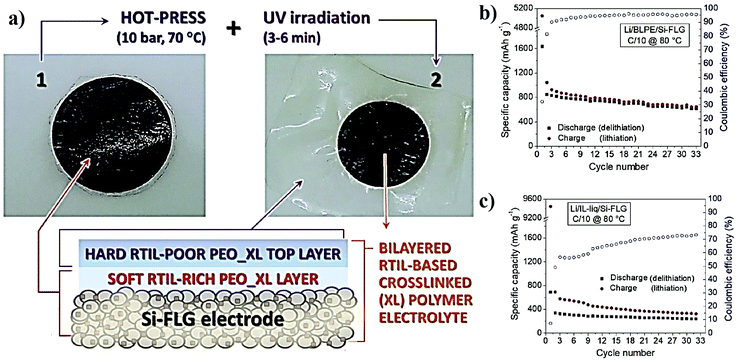 | ||
| Fig. 29 (a) Digital images of the Si–FLG electode integrated with BLPE. A schematic illustration of the soft-PIS layer and the subsequent hard IGPE layer over the Si–FLG electrode is also shown. Electrochemical cycling performance of the (b) Si–FLG|BLPE|Li and (c) Si–FLG|RTIL|Li cell at 80 °C (reproduced/adapted from ref. 362 with permission from Elsevier, Copyright 2020.362 Distributed under a Creative Commons Attribution-NonCommercial-NoDerivatives License International 4.0 (CC BY-NC-ND 4.0) (https://creativecommons.org/licenses/by-nc-nd/4.0/)). | ||
In summary, Section 5 provides an overview of the various types of in situ processing approaches used for the fabrication of LIPB and LMPB cells by employing free-radical polymerization techniques. Thermal curing and UV curing are the most used polymerization methods for the in situ process. The critical parameters that determine the properties of the in situ processed LPBs are the type of monomers, the number of functionalities, the type of spacer molecules in the oligomers, and the molecular weight of monomers/oligomers. All these characteristics will decide whether a PE that is formed is a tightly cross-linked or loosely cross-linked one. It is vital to find a balance between these two characteristics of the PE because properties such as ionic conductivity, volume changes of nano-sized active materials (V2O5, Si, etc.), and HSAL growth mainly depend on it. Acrylates and methacrylates are used for the free-radical polymerization process even though they show reactivity towards the Li metal anode due to the presence of ester groups. However, there are other functionalities such as epoxides and ester-free vinyl- and allyl-molecules that are suitable against the Li-metal anode, which must be further explored. Additionally, cross-linked PEs find application in S‖Li cells owing to their capability to minimize polysulfide shuttling, which is one of the most notorious problems of such advanced battery systems. Apart from conventional free-radical polymerization reactions following Norrish type-I or a similar type of thermal polymerization mechanism, hydrogen abstraction by Norrish type-II initiators and click-chemistry (thiol–ene, thiol–epoxide, etc.) have also been increasingly employed recently for the in situ process. The in situ processing approach is highly advantageous from a futuristic and practical perspective as tailor-made components such as artificial PIS-SEIs or PIS-CEIs can be judiciously engineered. Such tailor-made interphases can also be important in futuristic and industry-friendly methods like the multi-layer processing of LPBs, where individual PE and artificial interphase layers can be designed according to the end application. Indeed, the free-radical polymerization reaction, which is well established and the in situ widely used in the coating industry, is highly suitable to realize the multi-layer processing of LPBs. In Tables 2–5, the key performance indicators of the important reports discussed in Sections 5.1–5.3 are all compiled and presented.
| Acrylate/methacrylate | Plasticizer/salt/electrolyte/additive | Initiator | Type of polymerization | Ion transport properties (σ, TLi+, etc.) | Cell | Operating voltage range | Capacity | Capacity retention | Ref. |
|---|---|---|---|---|---|---|---|---|---|
*![[thin space (1/6-em)]](https://www.rsc.org/images/entities/char_2009.gif) Separator assisted. # Separator assisted. #![[thin space (1/6-em)]](https://www.rsc.org/images/entities/char_2009.gif) Direct deposition. $ Direct deposition. $![[thin space (1/6-em)]](https://www.rsc.org/images/entities/char_2009.gif) Multi-layer approach. Multi-layer approach. |
|||||||||
| Tetraethylene glycol diacrylate* | 1.1 M LiPF6/EC:PC:EMC:DEC | BPO | Thermal | 6.34 mS cm−1 at 20 °C | LCO|GPE|graphite | 3–4.2 V | 57 mA h (0.5C, 20 °C) | 90%, 40 cycles, 0.5C | 385 |
| PEGA* | 1 M LiPF6/EC:PC:EMC:DEC | BBP | Thermal | 6.2 mS cm−1 at RT | NMC|GPE|Li | 2.8–4.4 V | 164 mA h g−1 (0.2C, 20 °C) | — | 363 |
| PEGA* | 1 M LiPF6/EC:PC:EMC:DEC | BBP | Thermal | 6.2 mS cm−1 at RT | NMC|GPE|graphite | 2.8–4.4 V | 160 mA h g−1 (0.2C, 20 °C) | 90%, 300 cycles, 0.5C | 363 |
| TEGDMA* | 1 M LiPF6/EC:DEC | BPO | Thermal | 5.9 mS cm−1 at 20 °C | LCO|GPE|graphite (Pouch bag) | 3–4.2 V | 675 mA h (0.5C, 25 °C) | 100%, 20 cycles, 0.5C | 343 |
| BDDA* | 1 M LiPF6/EC:EMC:DMC | AIBN | Thermal | 3.2 mS cm−1 at 20 °C | LCO|GPE|MCMB (Pouch bag) | 2.75–4.2 V | 757 mA h, (0.5C, 20 °C) | 85%, 300 cycles, 0.5C | 392 |
| MMA* | 1 M LiPF6/EC:DEC | — | γ-Irradiation | ≈1 mS cm−1 at RT | LNC|GPE|graphite | 3–4.2 V | 145 mA h g−1 (0.2 mA cm−2, RT) | 85%, 20 cycles | 331 |
| PEGDMA* | 1 M LiPF6/EC:DEC, VC | TAPP | Thermal | ≈1 mS cm−1 at 25 °C | LVO|GPE|Li | 2–3.6 V | 220 mA h g−1 (0.2C, RT) | >85%, 100 cycles | 395 |
| TPGDA supported on SiO2* | 1 M LiPF6/EC:EMC:DMC | AIBN | Thermal | 1.74 mS cm−1 at RT | LFP|gel-PCE|Li | 2.4–4.2 V | 160 mA h g−1 (0.2C, 25 °C) | 100%, 200 cycles, 0.2C | 390 |
| PMIT* | 1 M LiBF6/EC:DEC, FEC | TAPP | Thermal | 1 mS cm−1 at RT | LCO|GPE|Li | 3–4.2 V | 134 mA h g−1 (0.2C, 25 °C) | 90%, 50 cycles, 0.2C | 428 |
| MHBIm-TFSI, PEGDA* | 0.5 M LiTFSI | AIBN | Thermal | 1.3 mS cm−1 at 30 °C | LFP|IPN–GPE|Li | 2.5–4 V | 152 mA h g−1 (0.1C, 40 °C) | 94%, 100 cycles, 0.1C | 429 |
| BEMA, PEGMEM# | LiTFSI/EC:DEC | HMPP | UV | — | V2O5|GPE|Li | 2.5–3.8 V | 130 mA h g−1 (1.5C, RT) | Stable over 500 cycles | 354 |
| BEMA, PEGMEM# | LiTFSI, PY1201-TFSI, and PC | HMPP | UV | ≈1 mS cm−1 at 25 °C | LFP|IGPE|Li | 2.5–4 V | 85 mA h g−1 (0.1C, RT) | Stable over 30 cycles | 369 |
| PEGMEM, PEGDMA# | LiMTFSI and PC | HMPP | UV | 0.11 mS cm−1 and a TLi+ of 0.88 at 25 °C | LFP|SIC-PE|Li | 2–4 V | 126 mA h g−1 (0.1C, 25 °C) | 98%, 100 cycles, 0.1C | 370 |
| BEMA with PEO# | LiTFSI | AAPH | Thermal | ≈0.01 mS cm−1 at RT | LFP|SPE|Li | 2.5–4 V | 140 mA h g−1 (1C, 70 °C) | 70%, 2000 cycles | 342 |
| BEMA# | LiTFSI and DPG | AIBN | Thermal | 0.14 mS cm−1 at 20 °C and a TLi+ of 0.45 | LFP|GPE|Li | 2.4–4 V | 130 mA h g−1 (0.1C, 25 °C) | 36%, 300 cycles | 396 |
| EGPEA# | 1 M LiPF6/EC:PC:EMC | AIBN | Thermal | 3.35 mS cm−1 at RT | NMC|GPE|Li | 2.8–4.6 V | 150 mA h g−1 (0.2C, 25 °C) | 100%, 70 cycles | 364 |
| PEGDA, PETMP (thiol)# | LiTFSI | DMPA | UV | 0.13 mS cm−1 at 60 °C | LFP|SPE|Li | 2.8–3.8 V | 139 mA h g−1 (0.1C, 60 °C) | 81%, 200 cycles | 388 |
| PEGDA$ | LiTFSI, LiBOB, and GN | Irgacure 819 | UV | 1 mS cm−1 at 30 °C | LFP|PCPE|Li | 2.5–3.9 V | 138 mA h g−1 (0.2C, 30 °C) | 86%, 370 cycles | 361 |
| Acrylate/methacrylate | Electrolyte/additive/plasticizer | Initiator | Type of polymerization | Ionic conductivity | Cell | Operating voltage range | Capacity | Capacity retention | Ref. |
|---|---|---|---|---|---|---|---|---|---|
*![[thin space (1/6-em)]](https://www.rsc.org/images/entities/char_2009.gif) Separator assisted. # Separator assisted. #![[thin space (1/6-em)]](https://www.rsc.org/images/entities/char_2009.gif) Direct deposition. Direct deposition. |
|||||||||
| TMPTMA* | 1 M LiPF6 in EC:EMC:DMC | LPO | Thermal | >1 mS cm−1 at 25 °C | LCO|GPE|graphite | 3–4.2 V | 129 mA h g−1, (2C, 25 °C) | ≈100%, 100 cycles, 0.2C | 412 |
| TMPTA* | LiTFSI in PC, PEGDME | AIBN | Thermal | ≈0.3 mS cm−1 at 25 °C | LFP|GPE|Li | 2.5–4.2 V | ≈150 mA h g−1 (1C, RT) | ≈100%, 100 cycles, 2C | 411 |
| ETPTA, HDDA# | 1 M LiTFSI in Pyr13-TFSI | HMPP | UV | 1.1 mS cm−1 at RT | LFP|IGPE|Li | 2–4.2 V | ≈100–120 mA h g−1 (0.2C, RT) | 100%, 50 cycles, 0.2C | 269 |
| PETEA* | 1 M LiPF6 in EC:DEC:EMC | AIBN | Thermal | 8.5 mS cm−1 at 25 °C | NCA|GPE|graphite | 2.75–4.5 V | 1.88 A h (5C, 25 °C) | 92.5%, 200 cycles, 5C | 417 |
| PETEA* | 1 M LiTFSI in 1,2-DOL:DME, LiNO3 | AIBN | Thermal | 11 mS cm−1 at 25 °C | S|GPE|Li | 1.7–2.8 V | 601 mA h g−1 (1C, 25 °C) | 82%, 400 cycles, 0.5C | 418 |
| PETEA* | 1 M LiTFSI in 1,2-DOL:DME, LiNO3 | AIBN | Thermal | 1 mS cm−1 at 25 °C | S|GPE|Li | 1.7–2.8 V | 486 mA h g−1 at 5C and 25 °C | 83%, 500 cycles, 0.3C | 419 |
| Acrylate/methacrylate | Electrolyte/salt/additive | Initiator | Type of polymerization | Ion transport properties (σ, TLi+etc.) | Cell | Operating voltage range | Capacity | Capacity retention | Ref. |
|---|---|---|---|---|---|---|---|---|---|
*![[thin space (1/6-em)]](https://www.rsc.org/images/entities/char_2009.gif) Separator assisted. Separator assisted. |
|||||||||
| Siloxane acrylate* | 1 M LiClO4 in EC:DMC (1![[thin space (1/6-em)]](https://www.rsc.org/images/entities/char_2009.gif) : :![[thin space (1/6-em)]](https://www.rsc.org/images/entities/char_2009.gif) 1) 1) |
TBPP | Thermal | 1.3 mS cm−1 at RT | LCO|GPE|MCMB | 2.8–4.2 V | 137 mA h g−1 (0.5C, RT) | 84%, 100 cycles, 0.5C | 437 |
| TAEP* | 1 M LiClO4 in EC:DMC (1![[thin space (1/6-em)]](https://www.rsc.org/images/entities/char_2009.gif) : :![[thin space (1/6-em)]](https://www.rsc.org/images/entities/char_2009.gif) 1) 1) |
TBPP | Thermal | 0.2–0.5 mS cm−1 at RT | LCO|GPE|MCMB | 2.8–4.2 V | 122 mA h g−1 (0.5C, RT) | 95%, 250 cycles, 0.5C | 438 |
| FTGA* | 1 M LiClO4 in EC:DMC (1![[thin space (1/6-em)]](https://www.rsc.org/images/entities/char_2009.gif) : :![[thin space (1/6-em)]](https://www.rsc.org/images/entities/char_2009.gif) 1) 1) |
TBPP | Thermal | 0.56 mS cm−1 at RT | LCO|GPE|MCMB | 2.8–4.2 V | 142 mA h g−1 (0.5C, RT) | 89%, 200 cycles, 0.5C | 439 |
| Boron containing methacrylates* | 1 M LiTFSI in EC:DMC (1![[thin space (1/6-em)]](https://www.rsc.org/images/entities/char_2009.gif) : :![[thin space (1/6-em)]](https://www.rsc.org/images/entities/char_2009.gif) 1) 1) |
AIBN | Thermal | 0.084 mS cm−1 at 30 °C with a TLi+ of 0.76 | LFP|GPE|Li | 2.5–4 V | 118 mA h g−1 (0.5C, 30 °C) | 90%, 400 cycles, 0.5C | 366 |
| Acrylate- or methacrylate-free molecule | Electrolyte/salt | Initiator | Type of polymerization | Ionic conductivity | Cell | Operating voltage range | Capacity | Capacity retention | Ref. |
|---|---|---|---|---|---|---|---|---|---|
*![[thin space (1/6-em)]](https://www.rsc.org/images/entities/char_2009.gif) Separator assisted. # Separator assisted. #![[thin space (1/6-em)]](https://www.rsc.org/images/entities/char_2009.gif) Direct deposition. Direct deposition. |
|||||||||
| PAEC# | LiTFSI | DMPA | UV | 0.0004 mS cm−1 at 25 °C | V2O5|SPE|Li | 2–4 V | — | — | 445 |
| Allyl PEO, allyl gallic acid, BPT (thiol)# | LiTFSI | BPO | UV | 0.4 mS cm−1 at 60 °C | LFP|SPE|Li | 2.5–4.2 V | 150 mA h g−1 (0.1C, 60 °C) | 88%, 50 cycles, 0.1C | 453 |
| Tetraglyme, PEO# | LiTFSI | MBP | UV | >0.1 mS cm−1 at 25 °C | TiO2|SPE|Li | 1–3 V | 140 mA h g−1 (0.1 mA cm−2, 20 °C) | Stable >100 cycles, 0.1 mA cm−2 | 375 |
| VC* | LiDFOB | AIBN | Thermal | 0.022 mS cm−1 at 25 °C | LCO|SPE|Li | 2.5–4.3 V | 146 mA h g−1 (0.1C, 50 °C) | 84%, 150 cycles, 0.1C | 443 |
| VC* | 1 M LiDFOB in EC:DEC | AIBN | Thermal | 0.56 mS cm−1 at 25 °C | LFMP|GPE|graphite | 2.5–4.35 V | 120 mA h g−1 (1C, 25 °C) | 89%, 1000 cycles, 1C | 444 |
6. In situ polymerization by miscellaneous methods
In the thermal- and photo-assisted in situ polymerization process, an external free-radical initiator is inevitable to trigger the polymerization reaction unless hazardous high energy radiation such as γ-rays is used. Although present in tiny quantities, the residues of un-reacted free-radical initiators may incite undesirable effects on the cycling performance of the cell. Thus, there are attempts to carry out the in situ processing of PEs and related battery cells in the absence of additional substances such as initiators. Ionic polymerization methods such as cationic and anionic polymerization are the frontrunners in this respect.470–473 Besides, in situ electropolymerization and condensation polymerization methods are also suitably employed to achieve similar results. One of the key advantages of these polymerization methods is that a variety of monomers such as epoxides, acrylates, methacrylates, allyl and vinyl ethers, azides, alcohols, carboxylates, and aldehydes can be used. Additionally, in many cases, these methods are also less sensitive to atmospheric conditions than free-radical polymerization. Besides, they are equally useful for producing artificial PIS-interphase-based surface protection as well. Recently, all these polymerization methods have gained a lot of attention and can be considered as potential competitors to the free-radical polymerization methods. In the following sections, the type of in situ process adopted (separator assisted, direct deposition, and surface protection approaches) is classified and highlighted wherever applicable.6.1 Anionic polymerization
Anionic polymerization is one of the types of addition (chain-growth) polymerization in which the growing chain head that carries a negative charge is balanced by a counter cation.475 Anionic polymerization is initiated by nucleophilic reagents (metal alkoxides, organolithium compounds, Grignard reagents, etc.).476 A list of commonly used initiators for the anionic polymerization reaction is summarized in Fig. 30a.469 Generally, the monomers employed in anionic addition polymerization are vinyl monomers with electron-withdrawing groups (e.g., MMA, acrylonitrile, 2-vinylpyridine, etc.) and conjugated monomers (styrene and 1,3-butadiene).469 The types of monomers that can undergo the anionic polymerization reaction are also listed in Fig. 30b.469 Anionic polymerization is often also called living polymerization as the propagation reaction continues without termination under suitable conditions.477 Living polymerization facilitates the controlled construction of various polymer structures so that various types of well-defined copolymers such as block copolymers can be made by the sequential addition of different types of monomers. Anionic addition (co)polymerization is employed to produce industrially relevant polymers such as synthetic rubbers (styrene-butadiene rubbers, SBR), thermoplastic elastomers, and ABA triblock copolymers (e.g., polystyrene-b-polybutadiene-b-polystyrene, SBS). Additionally, the same technique can also be used for ring-opening polymerization (ROP) or popularly called anionic ROP (AROP) of cyclic monomers having high electrophilicity.478 Heterocyclic compounds such as epoxides, episulfides and other cyclic compounds having carbonyl groups (lactones, cyclic carbonates, lactams, etc.) undergo a nucleophilic attack by the initiators to undergo AROP. For example, the general mechanism of AROP of epoxides initiated by alkali metal alkoxides is presented in Fig. 31.474 The reagents used and the initiating and propagating chains formed during the anionic polymerization reaction bear high basicity and nucleophilicity; thus, stringent experimental conditions are required. Hence, the presence of water and oxygen should be generally avoided, and an inert atmosphere (N2, Ar, or a high vacuum) must be used to ensure high reproducibility depending on the type of initiators and monomers used. The types of monomers and their electrophilicity, initiators and their nucleophilicity or basicity, and reaction conditions (low temperature is preferred due to the high reactivity and stability issues of the initiators and propagating chains) influence the polymerization process. Besides, the stability, polarity, and melting point of the solvents are also crucial. The most commonly employed solvents for anionic polymerization include THF, diethyl ether, benzene, toluene, etc.477,479,480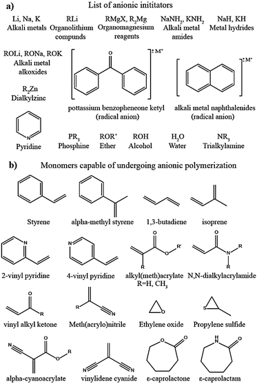 | ||
| Fig. 30 (a) List of commonly used species that can initiate the anionic polymerization reaction; and (b) list of monomers capable of undergoing the anionic polymerization reaction.469 | ||
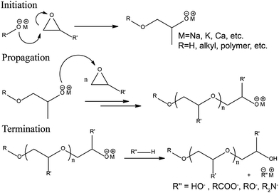 | ||
| Fig. 31 Steps involved in the AROP reaction mechanism of epoxides initiated by alkali-metal alkoxides (reproduced/adapted from ref. 474 with permission from Elsevier, Copyright 2013474). | ||
The in situ processing of LBs has been carried out through the anionic polymerization strategy; however, research work in this direction is scarce. Hence, there is room for exploring the suitability of this technique for the in situ processing of PEs and PIS-interphase layers and related device fabrication. For example, cyanoacrylate monomers are one of the most studied for this purpose,482–485 which provide several advantages such as the Lewis acid–base interaction of nitrile and acrylate groups with Li+-ions leading to complete salt dissociation as well as increased ion transport.486 In cyanoacrylates, the strong electron-withdrawing nitrile moiety is covalently linked to the unsaturated α-carbon atom of the acrylate group.487 Therefore, the β-carbon becomes highly electrophilic, resulting in high-reactivity for cyanoacrylate monomers. Unlike the free-radical polymerization pathway in the presence of an external initiator and energy source, anionic polymerization is energy efficient and can be carried out even at ambient temperature. Moreover, a lower polymerization activation energy and long-living active center are added advantages.
The anionic polymerization of the ethyl cyanoacrylate (ECA) monomer initiated by Li-metal (see Fig. 32a) is a novel approach for LMPB fabrication and also for Li-metal surface protection by the in situ process.481 Transfer of electrons from the Li-metal to the unsaturated double bond results in the generation of anionic active species to initiate the polymerization reaction. For instance, a precursor composed of 1 mL ECA, 3 mL of 4 M LiClO4 in EC:DMC, and 100 ppm of Li-powder (acts as the initiator) was employed by Cui et al. for the preparation of a GPE. Most importantly, the GPE could be formed in 2 h in the absence of external catalysts, initiators, or energy sources such as light or heat, unlike the conventional free-radical polymerization methods. It is worth noting that a nonfluorinated salt, such as LiClO4, is used as the Li+-ion source since the HF and PF5 impurities from LiPF6 can terminate the active anionic center. The GPE film, when prepared alone, could display an ionic conductivity of 2.7 mS cm−1 (RT), with a TLi+ of 0.48, and an oxidative stability value of 4.8 V vs. Li|Li+. Finally, an LMPB is in situ processed by the direct deposition approach over the composite cathode film. The low viscosity ECA can easily penetrate the deeper regions of the cathode composite, which is otherwise not possible with the ex situ processed GPE film. The in situ processed LFP|PECA–GPE|Li cell delivers a discharge capacity of 140 mA h g−1 (1C) with a retention of 90% (100 cycles) [Fig. 32b and c]. Additionally, a high voltage LNMO|PECA–GPE|Li cell is also assembled, which exhibits a discharge capacity of 122 mA h g−1 (1C) with a retention of 93% (100 cycles) [Fig. 32d and e]. In another report, the ECA monomer is explored to protect the surface of a high-voltage LNMO cathode by the formation of a PIS-CEI.346 It is shown that the in situ polymerized conformal coating (10 nm) of the PECA-based PIS-CEI could reduce the dissolution of the multivalent cations owing to the strong interactions with the N and O atoms of the cyano-ester moieties present in the PECA (Fig. 33a). This is reflected in the high cycling stability of PECA-coated LNMO (92% retention after 100 cycles) as compared to that of the non-coated counterpart (72% retention after 100 cycles) [Fig. 33b and c].
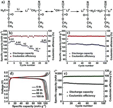 | ||
| Fig. 32 (a) The anionic polymerization mechanism involved in the conversion of ECA to PECA is initiated by Li-metal. In the first step, the transfer of an electron from Li-metal to the unsaturated double bond in ECA occurs, resulting in the generation of an active anionic species. This anionic species further propagates the polymerization of ECA. (b) and (c) present the specific capacity values at different C-rates and the cycling stability profile of the LFP|PECA-GPE|Li cell, respectively, at RT. (d) and (e) present the galvanostatic charge–discharge and cycling stability profiles of the LNMO|PECA-GPE|Li cells, respectively, at RT (reproduced/adapted from ref. 481 with permission from American Chemical Society, Copyright 2017481). | ||
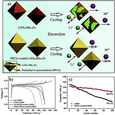 | ||
| Fig. 33 (a) The influence of a conformal coating of a PECA-based PIS-CEI layer over the LNMO cathode preventing the multivalent ion leaching into the electrolyte; and (b) galvanostatic charge–discharge profile, and (c) cycling stability profiles of the pristine and artificial PIS-CEI coated LNMO cathode-based LB cell (LNMO|LE|Li) (reproduced/adapted from ref. 346 with permission from Elsevier, Copyright 2017346). | ||
Similarly, the in situ processed PECA-based artificial PIS-SEI layer on the Li-metal surface is found to inhibit the inhomogeneous deposition/dissolution of Li-metal.488 This tailor-made surface protection can also be employed for improving the electrochemical behavior of the Li-metal anode even in a conventional LE-based LMB (LE-LMB). In a typical procedure, the precursor is prepared in acetone with ECA (ECA/acetone = 1![[thin space (1/6-em)]](https://www.rsc.org/images/entities/char_2009.gif) :
:![[thin space (1/6-em)]](https://www.rsc.org/images/entities/char_2009.gif) 5) and LiNO3 salt (0.1 M relative to acetone). This solution is applied over Li-metal, where the anionic polymerization at RT is initiated by LiOH present on the Li-metal surface (Fig. 34a). Hence, such anionic polymerization reactions can also be considered as a scavenging process in which the polymerization process removes the unwanted LiOH from the surface of the lithium metal. LE-LMB (LFP|LE|Li) cells are fabricated, where the LE has a composition of 1 M LiPF6 in EC:DMC. The LE-LMB cell delivers a specific capacity of 150 mA h g−1 (2C) with 100% capacity retention (500 cycles). The isolation effect by the PECA layer ensures a low polarizing voltage, a lower consumption of Li-metal through minimized side reactions, and a homogenous distribution of Li+-ion flux that suppresses the corrosion/pitting of the anode. The cycling performance of the PECA-based cell is superior to the PECA-free counterpart. Moreover, the high mechanical stability of PECA (Young's modulus of 25 GPa) is an added advantage, which can accommodate even the volume changes in the electrode. The effect of the PECA coating for facilitating the suppression of dendrite growth is illustrated in Fig. 34b, and the superiority of such a layer over the Li-metal surface of an LFP|LE|Li cell is also evident in the electrochemical cycling profiles presented in Fig. 34c.
5) and LiNO3 salt (0.1 M relative to acetone). This solution is applied over Li-metal, where the anionic polymerization at RT is initiated by LiOH present on the Li-metal surface (Fig. 34a). Hence, such anionic polymerization reactions can also be considered as a scavenging process in which the polymerization process removes the unwanted LiOH from the surface of the lithium metal. LE-LMB (LFP|LE|Li) cells are fabricated, where the LE has a composition of 1 M LiPF6 in EC:DMC. The LE-LMB cell delivers a specific capacity of 150 mA h g−1 (2C) with 100% capacity retention (500 cycles). The isolation effect by the PECA layer ensures a low polarizing voltage, a lower consumption of Li-metal through minimized side reactions, and a homogenous distribution of Li+-ion flux that suppresses the corrosion/pitting of the anode. The cycling performance of the PECA-based cell is superior to the PECA-free counterpart. Moreover, the high mechanical stability of PECA (Young's modulus of 25 GPa) is an added advantage, which can accommodate even the volume changes in the electrode. The effect of the PECA coating for facilitating the suppression of dendrite growth is illustrated in Fig. 34b, and the superiority of such a layer over the Li-metal surface of an LFP|LE|Li cell is also evident in the electrochemical cycling profiles presented in Fig. 34c.
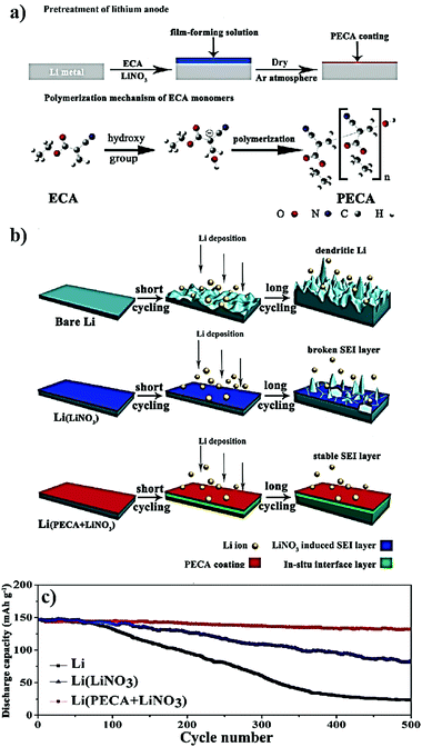 | ||
| Fig. 34 (a) Schematic representation of the pre-treatment of Li-metal by the ECA monomer to form an artificial PIS-SEI layer-based surface coating. The polymerization mechanism of ECA over the Li-metal surface, which is assisted by hydroxyl groups over Li-metal, is also depicted. (b) The bare Li-metal undergoes side reactions with the electrolyte, and dendrite growth starts within a few cycles. In the case of the LiNO3 coated Li-metal surface in the absence of a PECA coating, a non-polymeric SEI is formed, which is stable and prevents HSAL growth in the earlier cycles. However, the non-polymeric SEI breaks during prolonged cycling. Later, the in situ processed PECA-LiNO3 (PIS-SEI) layer over the Li-metal surface effectively prevents HSAL growth even after a high number of charge–discharge cycles, imparting high cycling stability. (c) Cycling profiles depicting the advantage of the PECA coating imparting high stability over the PECA non-coated counterparts (reproduced/adapted from ref. 488 with permission from American Chemical Society, Copyright 2017488). | ||
There are also attempts to make LMPBs smarter using the in situ anionic polymerization method. For instance, thermal runaway is one of the failure mechanisms of LBs, where the temperature inside the cell is increased because of exothermic reactions. The heat generated inside the cell due to the thermal runaway reaction often leads to destructive developments such as explosion or fire. There can be several reasons for the thermal runaway reaction, which include short-circuit, overcharging, HSAL growth, damaged cell components, or even a failure in the battery management system (BMS). In an LB stack, the thermal runaway can be catastrophic as the failure of even a single cell can propel a cascade of reactions, and the resulting exponential increase in temperature causes a complete loss of the battery system. The initiator-free polymerization approach of VC to poly-VC in the presence of LiI is used as a tool for triggering the thermal shutdown of the LMPB cell by sensing any potential failure due to thermal runaway (Fig. 35a).489 This work can be considered as an example of the in situ process for injecting smartness into the battery, where the separator assisted approach is employed. Here, LiI plays multiple roles as a catalyst for the ring-opening polymerization of VC and a Li+-ion source in the resulting GPE. Thermal curing at 80 °C for 1 h is required for the VC to poly-VC conversion. Indeed, the authors claim that the polymerization of VC occurs through the formation of lithium iodoalkoxide, which is a byproduct formed during the decarboxylation of VC by iodide (I−) ions during the initiation step. The mechanism of the polymerization reaction, as claimed by the authors, is provided in Fig. 35b. Although the GPE displayed an ionic conductivity of 1.8 mS cm−1 (25 °C), the oxidative stability is limited by the presence of iodide ions in the electrolyte (3.5 V vs. Li|Li+). Therefore, LiI induced anionic polymerization is not suitable for high-voltage applications; nevertheless, the functioning of an LTO|GPE|Li cell (LMPB cell) cycling (RT) between 1 and 2 V is demonstrated, which retains 50% of the initial specific capacity (75 mA h g−1) after 700 cycles. It should be noted that the conversion of VC to poly-VC is not complete in the GPE so that further polymerization would still be possible during the operation of the cell. Consequently, when the operating temperature of the battery cell is increased to 80 °C, a drastic increase in the electrolyte resistance by a factor of 103 is observed, indicating complete polymerization, which converts the GPE to a highly resistive SPE (Fig. 35e). Hence, the cell undergoes a self-shutdown mode due to the extremely high internal resistance incited by the SPE in line with the concept of imparting smartness to batteries. The self-shut down is evident from the charge–discharge profile presented in Fig. 35c, where the increase in temperature from 25 to 80 °C leads to cell failure, and corresponding cycling data is provided in Fig. 35d. This work opens up new opportunities with the in situ polymerization processing strategies to realize safer batteries with inbuilt sensing and safety mechanisms.
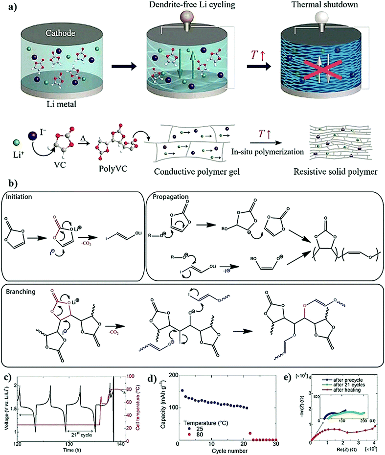 | ||
| Fig. 35 (a) Schematic representation of an LMPB cell with a poly-VC-based GPE featuring a thermal shut-down mechanism at elevated temperatures. When the operating temperature is raised to 80 °C, the complete polymerization of VC occurs, leading to the formation of an SPE, which is highly resistive. This triggers the cell shutdown. (b) The mechanism of VC to poly-VC conversion initiated by the attack of I− at the double bond of VC generating lithium iodoalkoxide, which further propagates the polymerization and branching. (c) and (d) present the galvanostatic charge–discharge profile and cycling stability, respectively, as a function of the increase in temperature. The cell failure at the 22nd cycle as the temperature is increased to 80 °C is evident. (e) The change in the Nyquist plot representing the increase in resistance when raising the temperature of the cell to 80 °C compared to that of a pre-cycled cell and after 21 cycles at 25 °C (reproduced/adapted from ref. 489 with permission from The Royal Society of Chemistry489). | ||
6.2 Cationic polymerization
Cationic polymerization is also an addition (chain-growth) polymerization, in which the growing chain head is carrying a positive charge balanced by a counter anion.490 Cationic addition polymerization (CAP) is usually applied for vinyl monomers with electron-donating groups in the presence of an electrophilic agent acting as the initiator (e.g., Brønsted acids: HClO4 and CF3SO3H, Lewis acids: BF3 and SnCl4, and carbenium ions: trityl and tropylium).491 Lewis acids alone or along with another protonogen (water or alcohol) or a cationogen (alkyl halides) can also be used for the in situ formation of strong protonic acids (high pKa value) and subsequent initiation of cationic polymerization. In this case, the cation donor and the Lewis acid species are called the initiator and co-initiator, respectively.492 For instance, a Lewis acid such as BF3 with water forms an ideal initiating system such as H+(BF3OH)−. A few of the typical vinyl monomers that are used for cationic polymerization are listed in Fig. 36a.490 Cationic polymerization is often used to produce industrially important polymers such as polyisobutylene (PIB), butyl rubber, and poly(vinyl ethers) (PVEs).491,493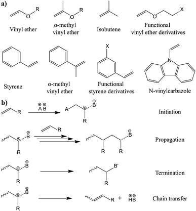 | ||
| Fig. 36 (a) A few examples of vinyl monomers that can undergo cationic polymerization; and (b) the mechanism of polymerization of vinyl monomers in the presence of a typical protic acid (A = H).490 | ||
The cationic polymerization mechanism of a vinyl monomer initiated by a typical protic acid is presented in Fig. 36b (A in the chemical structure represents an H atom).490 The reaction starts with an electrophilic addition of a proton onto the electron-rich alkene to produce a carbocation (sp2-hybridized) with a counter anion balancing the charge. The initiating species undergoes further continuous addition of monomers (propagation reaction) to form a long polymeric chain. The propagating reaction follows a chain-growth mechanism. The stability of the carbocation is very important in cationic polymerization, which depends upon the type of initiator used or the anion formed during the initiation process. Besides, the choice of solvent is also very critical in CAP due to the tendency of the system to undergo side reactions such as termination and chain transfer. The polymerization reaction is favored in polar solvents; hence, aliphatic, aromatic, and halogenated hydrocarbons are widely employed as suitable solvents. However, alcohols, water, and other basic solvents (e.g., esters, ethers, etc.) should be avoided as they promote unwanted side reactions. Due to the higher sensitivity of cationic polymerization reactions, stringent reaction conditions should be employed.
ROP can also be carried out using a cationic polymerization pathway, and such processes are called cationic ring-opening polymerization or simply CROP. The few heterocyclic monomers that can be polymerized through the CROP process are listed in Fig. 37a.494–496 As an example, the CROP mechanism of an oxetane monomer in the presence of a protic acid is also illustrated in Fig. 37b.497 The solvent, reaction conditions, and initiators used for CROP are similar to the CAP reaction. It is worth noting that CROP generally occurs through an SN1 or SN2 mechanism,497 and in many cases (for THF and oxetane) CROP also achieves a living character (no termination). Hence, it can also be used for producing structurally well-defined polymers.498 The following section covers the in situ processing of LPB cells using cationic polymerization.
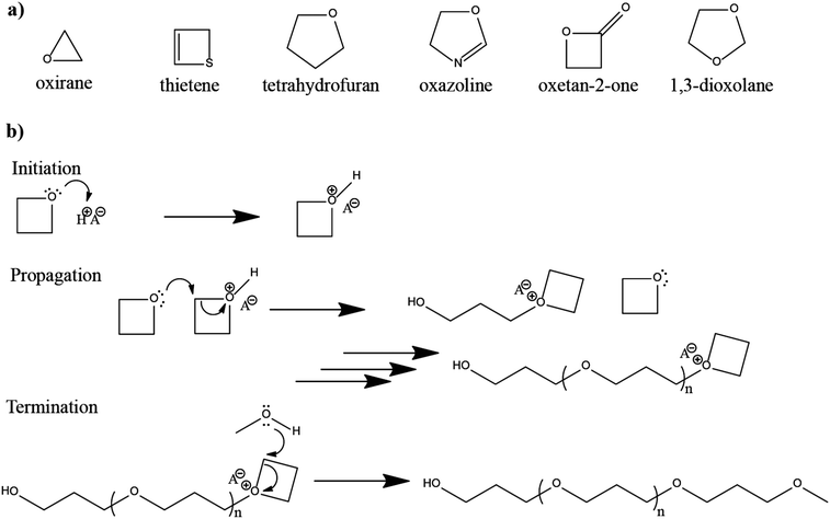 | ||
| Fig. 37 (a) A few examples of the cyclic monomers that can undergo the CROP reaction; and (b) general mechanism involved in the CROP reaction of the oxetane molecule. Epoxide and tetrahydrofuran molecules can also undergo CROP reactions in a similar fashion.497 | ||
Hwang et al. reported the separator assisted approach for LMPB (LCO|GPE|Li) fabrication using a GPE derived from a divinyl ether oligomer by CAP.499 The homogenous precursor solution is composed of a bi-functional oligomer [tri(ethylene glycol) divinyl ether, TEGDVE], LE (1 M LiBETI in EC:DEC), and additional LiBF4 salt. The polymerization is carried out at RT, where LiBF4 plays multiple roles as a cationic initiator and a conducting Li-salt. Compared to other reports using acidic initiators such as protic acids, Lewis acids, or a mixture of both, in this work, the generation of H+BF4− from LiBF4 initiates the polymerization reaction. The general mechanism of the polymerization of a (di)vinyl ether oligomer is presented in Fig. 38a. Any harmful effects due to the addition of external acidic initiators or nonhomogeneous polymerization are also avoided as the LiBF4 salt is homogenously dissolved in the precursor and hence called external initiator-free polymerization. The prepared GPE possesses an ionic conductivity of ≈1 mS cm−1 (at 30 °C) with high oxidative stability (5 V vs. Li|Li+). The assembled LMPB cell displayed a discharge capacity of 150 mA h g−1 (15 mA g−1).
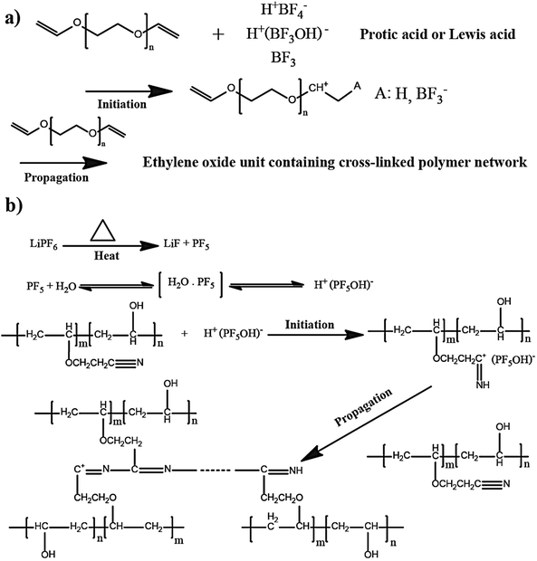 | ||
| Fig. 38 (a) Mechanism of cationic polymerization of the divinyl ether monomer (reproduced/adapted from ref. 499 with permission from Elsevier, Copyright 2010499); and (b) polymerization mechanism of PVA-CN initiated by H+(PF5OH)− (reproduced/adapted from ref. 500 with permission from The Royal Society of Chemistry500). | ||
Kang et al. reported a separator assisted approach for preparing a cross-linked GPE and fabrication of an LIPB cell using a precursor containing a cyanoethyl polyvinyl alcohol (PVA-CN)-based functional monomer. According to the authors, even in this case, a Lewis acid-based initiator (PF5) is in situ generated during the thermal decomposition of LiPF6 salt present in the precursor.500 The formed PF5 reacts with a trace amount of water present in the precursor (2 wt% PVA-CN dissolved in 1 M LiPF6 in EC:DMC:EMC), generating the protic acid H+(PF5OH)−, which in turn initiates the cationic gelation process. However, the decomposition of LiPF6 salt is a concern in LIBs. The side products formed such as PF5 and POF3 are hazardous, and some of these reactions in the presence of water create HF, which is unfavorable for achieving long-term cyclability. Additionally, the presence of HF can further catalyze many side reactions, including the degradation of high voltage cathodes such as NMC. Hence, a suitable salt system must be selected for initiating the polymerization reaction. A plausible polymerization mechanism for PVA-CN polymerization is provided in Fig. 38b. Herein, LIPB pouch cells (LCO|GPE|graphite) with a total capacity of 2100 mA h are assembled by two different techniques using separator assisted in situ processing using cationic polymerization of PVA-CN: (technology 1) gelation before the battery formation cycle, and (technology 2) gelation after the battery formation cycle (see Fig. 39a).500 The LIPB cell prepared using technology 1 exhibited a low total discharge capacity of 1939 mA h (0.2C) [Fig. 39b and c] due to the poorly performing highly resistive interphase layer at the GPE|graphite interface. Besides, near to the surface of the electrode, trapped bubbles are also observed, which results in bad interfacial contact. In the LIPB cell fabricated using technology 2, a bubble-free electrode|electrolyte interface with a higher capacity of 2086 mA h is obtained, close to that of an LE-based LIB. In another report from the same group, plastic crystals (succinonitrile, SN) are also incorporated into the precursor along with PVA-CN and LiPF6 (Fig. 40a).501 SN is a commonly used plastic crystal in the preparation of PEs, which improves the ionic conductivity owing to its high polarity.502,503 Herein, the GPE (PCPE) (namely, SEN) exhibits a high ionic conductivity of 2.32 mS cm−1 (25 °C) along with an overall broad oxidative stability value (5 V vs. Li|Li+). Interestingly, the SEN also showed a TLi+ of 0.57 and activation energy of 0.04eV, which are good values for any GPEs. Finally, the in situ processed LMPB cell (LFP|SEN|Li) displayed an initial discharge capacity of 154.8 mA h g−1 (0.1C) with a good capacity retention of 96.7% (100 cycles).
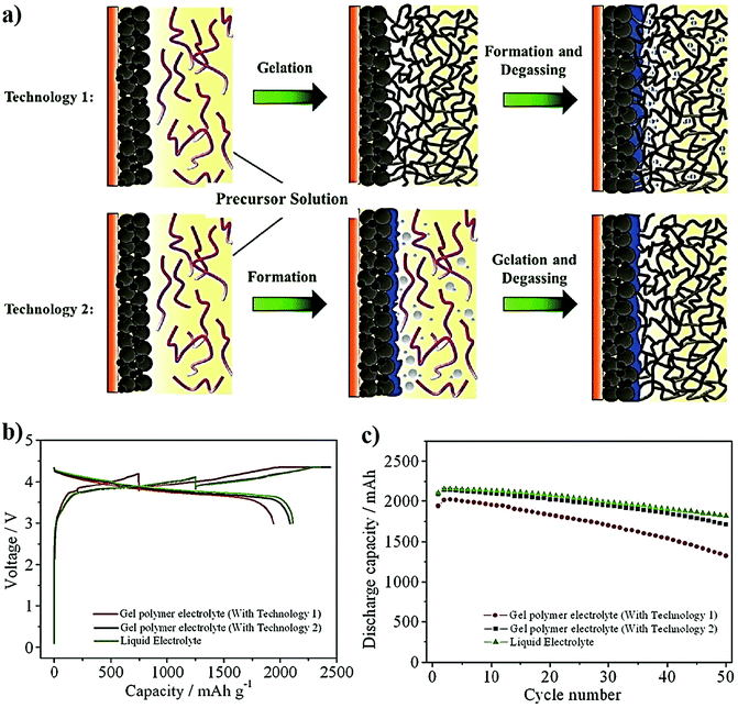 | ||
| Fig. 39 (a) The difference between technology 1 and 2 is schematically represented. Technology 1 involves GPE preparation by the in situ process before the formation cycle of the battery cell, whereas technology 2 is after the formation cycle. (b) and (c) present the improved electrochemical performance of the LIPB cell using technique 2, which is comparable to the LE-based cell (reproduced/adapted from ref. 500 with permission from The Royal Society of Chemistry500). | ||
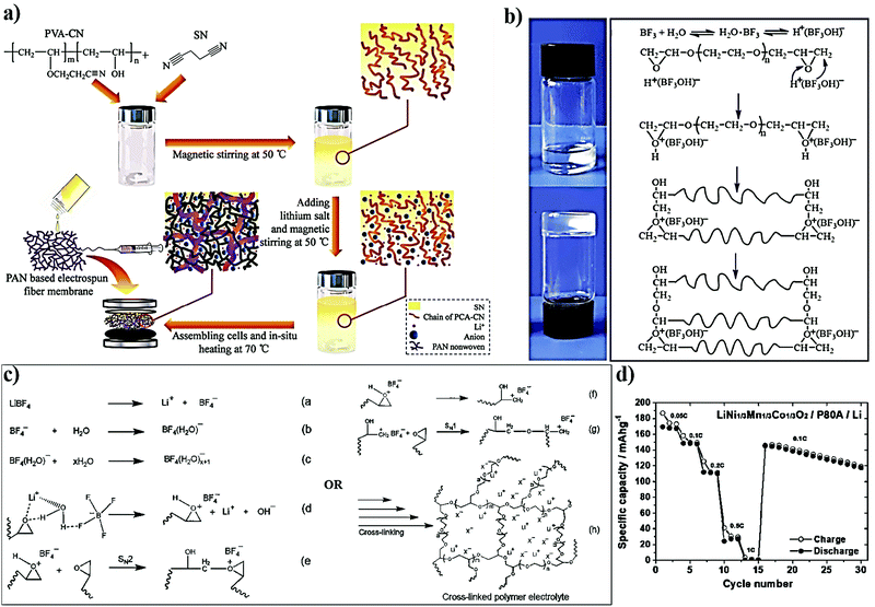 | ||
| Fig. 40 (a) Scheme depicting the synthesis of SEN (PCPE) by cationic polymerization of PVA-CN followed by the in situ fabrication of the LMPB cell by the separator assisted approach (reproduced/adapted from ref. 501 with permission from John Wiley and Sons, Copyright 2015501). (b) Cationic polymerization mechanism involved in the polymerization of diglycydyl ether (PEGDE). The cationic initiator species is H+(BF3OH)− formed by the reaction of BF3 with trace water present in the reaction mixture (reproduced/adapted from ref. 504 with permission from John Wiley and Sons, Copyright 2017.504 Distributed under a Creative Commons Attribution License International 4.0 (CC BY 4.0) (https://creativecommons.org/licenses/by/4.0/)). (c) New mechanism suggested by Nair et al. for the CROP of the diglycidyl ether oligomer leading to an SPE and fabrication of LMPB cells by the in situ process. Here, it is proven that the anions in combination with water can initiate the polymerization without decomposing into BF3OH and HF. (d) presents the electrochemical performance of the in situ processed (direct deposition) LMPB cell (NMC111|SPE|Li) at 60 °C (reproduced/adapted from ref. 505 with permission from American Chemical Society, Copyright 2019505). | ||
In a recent report, synthesis of a cross-linked poly(ethylene glycol) diglycidyl ether (PEGDE)-based SPE by the CROP pathway is used for LMPB cell fabrication.504 The epoxy ring in the PEGDGE is opened by the in situ generated cationic initiator species [H+(BF3OH)−]. According to the authors, disproportionation of LiDFOB salt at 80 °C produces the Lewis acid BF3, which reacts with trace amounts of water to form the protic acid, H+(BF3OH)−. A monomer to polymer conversion of 90% is achieved, and the reported polymerization mechanism is presented in Fig. 40b. According to the report, other salts such as LiClO4, LiBF4, and LiPF6 can also undergo a similar kind of initiation process. The cellulose reinforced SPE (C-PEGDE) exhibits an ionic conductivity of 0.089 mS cm−1 at ambient temperature with an oxidative stability value of 4.5 V vs. Li|Li+. The LMPB cell (LFP|C-PEGDE|Li) is prepared by a separator assisted approach in which a homogenous precursor (1.25 wt% LiDFOB and 20 wt% LiTFSI in PEGDGE) is injected into the cellulose paper inside the test cell and cured at 80 °C (4 h). The reversible capacities of the LMPB cell at RT are about 115 mA h g−1 (0.1C), and, after 100 cycles, 74% of the initial specific capacity is also retained. In a recent report, Nair et al. have proposed a different mechanism for the CROP of the diglycidyl ether oligomer that can be used for the in situ processing of SPE-based LPBs by a separator assisted or a separator-free approach.505 The reported mechanism is shown in Fig. 40c, which demonstrates that the anions, in combination with a trace amount of water molecules, can initiate the CROP polymerization without decomposing into BF3OH and HF. This mechanism can also explain the capability of other Li-salts such as LiClO4 and LiFSI in initiating the CROP of cyclic ethers. The optimized SPE membrane with LiTFSI and LiBF4 also showed an ionic conductivity of 0.1 mS cm−1 (30 °C) and oxidative stability above 4.8 V vs. Li|Li+ due to the passivation behavior of BF4− anions during the oxidation process. Additionally, they have also demonstrated the electrochemical cycling performance of the cross-linked SPE in high-voltage NMC111 (LiNi0.33Mn0.33Co0.33O2) cathode-based LMPB cells, and the resulting specific capacity of the cell at different current rates is presented in Fig. 40d.
A more ingenious method for realizing an artificial PIS-CEI is introduced by combining both free-radical and cationic polymerization processes for the fabrication of high-voltage LNMO cathode-based LPB cells.347 Here, two precursors (A and B) are prepared in which solution A is composed of 30 wt% MMA and 10 wt% acrylic anhydride dissolved in 1 M LiPF6 in EC:DEC. Solution B contains 2-methyl-acrylic acid-2-oxirane-ethyl ester (MAEOE, 3.0 wt%) and an AIBN initiator (1 wt%) with the remaining fraction being methyl ethylene carbonate (MEC). On mixing solutions A and B, both CROP of MAEOE and heat-induced free-radical polymerization (50 °C) of MMA, MAEOE, and acrylic anhydride occur concurrently (Fig. 41a). The LiPF6 in the electrolyte reacts with trace amounts of water to form the cationic initiator species H+(PF5OH)−, to initiate the CROP.506,507 The cross-linked GPE (PAMM) is formed after 6 h, which displays good ionic conductivity (0.67 mS cm−1, RT) and high oxidative stability (5 V vs. Li|Li+). Indeed, the in situ processing of LPB cells is carried out by a separator assisted approach displayed an excellent cycling performance at RT and 55 °C due to the PAMM-based polymeric interphase (indeed, a PIS-CEI) layer formed over the LNMO cathode. The PIS-CEI created over the LNMO cathode helps minimize Mn2+ ion dissolution, hence increasing the life-span of the cell.508,509 A schematic representation of the role of PAMM in preventing Mn2+ dissolution compared to the PIS-CEI formed from the linear PMMA is given in Fig. 41b. The interaction of multivalent ions such as Mn2+ and Ni2+ with the anhydride group within the PAMM-based PIS-CEI layer is claimed to be the reason for the stabilization of the cathode, resulting in improved electrochemical performance. A GPE from a siloxane epoxide cross-linker and poly(2-vinylpyridine-co-styrene) (PVS) is also reported to be initiated by the in situ formed H+(PF5OH)− species.510 Here, it is reported that the GPE with 99 wt% LE delivers an extremely high ionic conductivity value of 11 mS cm−1 (30 °C) with large oxidative stability (5.2 V vs. Li|Li+). However, the extremely high LE content present in the GPE is a drawback for high-temperature applications and for achieving thinner packaging. Finally, it has been demonstrated that the separator assisted and in situ processed GPE-based LIPB cell (LCO|GPE|graphite) delivers a discharge capacity of 133.2 mA h g−1 at 0.1C (30 °C).
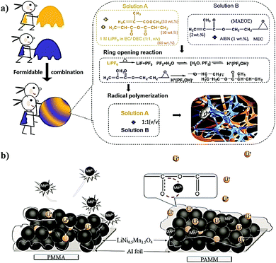 | ||
Fig. 41 (a) Combining both free-radical and cationic pathways as a potential strategy for the in situ processing of LB cells; and (b) the proposed mechanism depicting the suppression of Mn2+ dissolution owing to the formation of O![[double bond, length as m-dash]](https://www.rsc.org/images/entities/char_e001.gif) C–O–M (M = Mn, Ni) species in the PAMM-based PIS-CEI, which is absent in the PMMA-based PIS-CEI (reproduced/adapted from ref. 347 with permission from American Chemical Society, Copyright 2017347). C–O–M (M = Mn, Ni) species in the PAMM-based PIS-CEI, which is absent in the PMMA-based PIS-CEI (reproduced/adapted from ref. 347 with permission from American Chemical Society, Copyright 2017347). | ||
The latest advancement in the cationic assisted in situ polymerization process is converting a traditional LE to a GPE/SPE. Liu et al. recently conceived this approach for the fabrication of GPE-based LMPBs. Here, an ether-based LE (1,3-dioxolane, 1,3-DOL) is in situ polymerized using a separator assisted approach at ambient temperature in the presence of LiPF6 salt through a CROP pathway (1,2-dimethoxyethane, DME is used as a solvent).511 The mechanism can be explained as the ROP of 1,3-DOL assisted by the in situ generated H+(PF5OH)− species (Fig. 42a). Optical images of the liquid and GPEs are also shown in Fig. 42b. The 1,3-DOL molecule undergoes fast protonation to form oxonium ions followed by a ring-opening process, which can further attack more 1,3-DOL to propagate the polymerization reaction, achieving long polymer chains. The monomer to polymer conversion rate for 1,3-DOL is as high as 91%. It is observed that the number average molecular weight (Mn) of the resulting polymers reaches ≈52![[thin space (1/6-em)]](https://www.rsc.org/images/entities/char_2009.gif) 000 Da when the LE-mixture can react for 10 h. Indeed, the resulting GPE delivers an RT ionic conductivity of 3.8 mS cm−1. Compared to LEs, this GPE in a Li‖Li symmetric cell exhibits a significantly lower overpotential for the lithium plating/stripping process for prolonged cycling. The volume-changes and HSAL formation at the Li-metal surface are also minimized with the reported GPE. The adaptability of this method for the fabrication of LMPBs with various cathode materials such as LFP, NMC622, and sulfur has been demonstrated (Fig. 42c), which illustrates the overall good cycling performance using the in situ fabricated GPE-based cells. The SEM image of the S cathode before and after the GPE coating is shown in Fig. 42d and e, respectively. Indeed, the in situ confinement of the GPE is found to restrict the free diffusion of polysulfides, thus reducing the shuttling effect. At 0.5C, the S|GPE|Li cell delivers a discharge capacity of 1010 mA h g−1 by retaining 50% of the initial value after 500 cycles (Fig. 42f). Hence, 1,3-DOL to poly-DOL conversion inside the LB cell is indeed an excellent approach to improve the overall cycling performance of S‖Li cells.
000 Da when the LE-mixture can react for 10 h. Indeed, the resulting GPE delivers an RT ionic conductivity of 3.8 mS cm−1. Compared to LEs, this GPE in a Li‖Li symmetric cell exhibits a significantly lower overpotential for the lithium plating/stripping process for prolonged cycling. The volume-changes and HSAL formation at the Li-metal surface are also minimized with the reported GPE. The adaptability of this method for the fabrication of LMPBs with various cathode materials such as LFP, NMC622, and sulfur has been demonstrated (Fig. 42c), which illustrates the overall good cycling performance using the in situ fabricated GPE-based cells. The SEM image of the S cathode before and after the GPE coating is shown in Fig. 42d and e, respectively. Indeed, the in situ confinement of the GPE is found to restrict the free diffusion of polysulfides, thus reducing the shuttling effect. At 0.5C, the S|GPE|Li cell delivers a discharge capacity of 1010 mA h g−1 by retaining 50% of the initial value after 500 cycles (Fig. 42f). Hence, 1,3-DOL to poly-DOL conversion inside the LB cell is indeed an excellent approach to improve the overall cycling performance of S‖Li cells.
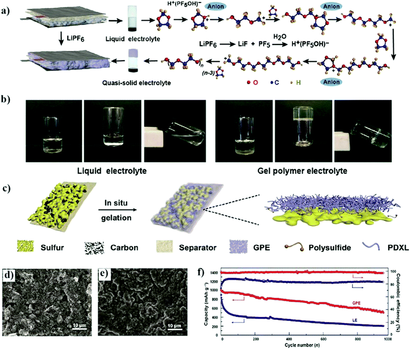 | ||
| Fig. 42 (a) The mechanism of cationic polymerization of the 1,3-DOL solvent to a GPE initiated by H+(PF5OH)− species at ambient temperature; (b) the photographs presenting the 1,3-DOL-based LE before and after polymerization; (c) the schematic representation of the in situ processed 1,3-DOL-based GPE supported by a porous separator over the S cathode inside the LB cell; the SEM images of the surface of the S cathode (d) before and (e) after GPE coating; and (f) cycling performance and Coulombic efficiency comparison of the in situ processed S|GPE|Li and S|LE|Li battery cells. The GPE performs better than the LE due to the reduced polysulfide shuttling between the anode and cathode.511 (Reprinted/Adapted from Reference 511. © The Authors, some rights reserved; exclusive licensee AAAS. Distributed under a Creative Commons Attribution NonCommercial License 4.0 (CC BY-NC) http://creativecommons.org/licenses/by-nc/4.0/.) | ||
In the recent work by Zhao et al., 1,3-DOL is converted to an SPE by CROP, followed by the separator assisted approach used for LMPB fabrication (Fig. 43a).334 In this work, the role of aluminum triflate (Al(OTf)3) salt as an electrolyte additive is proved to initiate the CROP reaction. The cationic aluminum species attacked by the oxygen atom of 1,3-DOL initiates ROP, producing poly-DOL with an Mn of 15000 Da (Fig. 43b). The ionic conductivity of the SPE is as high as 1 mS cm−1 (RT), which surpasses typical SPEs. However, the authors mention that the high RT ionic conductivity could be due to the unpolymerized 1,3-DOL or oligomers entangled within the poly-DOL matrix, which is clear from the lower ionic conductivity of 0.1 mS cm−1 obtained for the SPEs with a higher concentration of Al(OTf)3. Therefore, the poly-DOL formation should be judiciously controlled so that an optimum molecular weight of the polymer is obtained. The optimized poly-DOL-based SPE displays oxidative stability over 5 V vs. Li|Li+ and stable lithium plating/stripping over 200 h (areal capacity = 1 mA h cm−2). The morphology of the Li-metal anode after plating/stripping analysis in the case of the LE and SPE is presented in Fig. 43c and d, respectively. The smooth surface morphology of the plated Li for an SPE underlines the better interfacial properties achieved by the SPE over the LE. The authors reported three types of LMPB cells (S|SPE|Li, NMC622|SPE|Li, and LFP|SPE|Li) that are prepared and fully characterized at RT. In the case of the S|SPE|Li cell, the polysulfide shuttling is reduced, and the cell displays 98% Coulombic efficiency even after 100 cycles (at 0.1C), which is indicating the role of the in situ process in suppressing the side reactions. The charge–discharge profile of the S|SPE|Li cell at different current rates is provided in Fig. 43e. Similarly, the LFP and NMC622 cathode-based separator assisted in situ fabricated LMPB cells also show superior performance to their respective LE counterparts. Hence, from these examples, it can be summarized that the in situ processing of LPBs using the CROP reaction is an important approach for producing pure and long-lasting PEs, and more focused research in this direction will increase further opportunities.
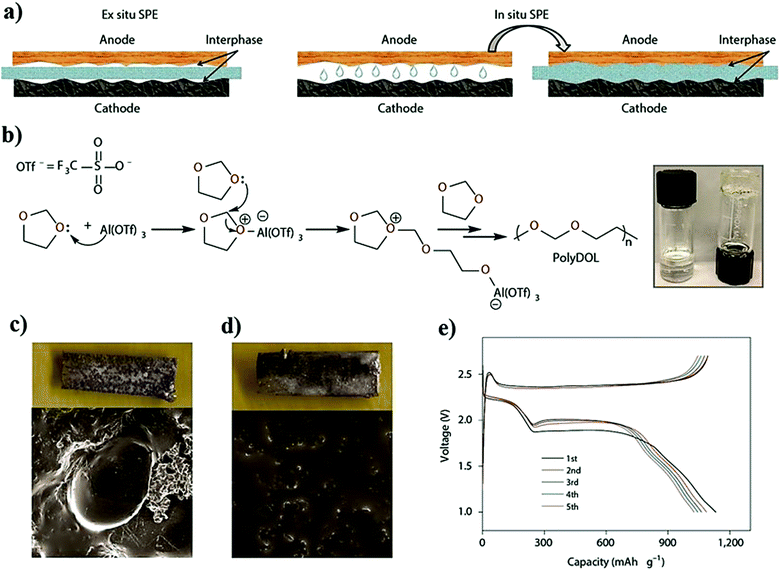 | ||
| Fig. 43 (a) Self-explanatory scheme illustrating the electrode|electrolyte interface in the ex situ and in situ processed SPE-based LB. (b) CROP mechanism for 1,3-DOL initiated by Al(OTf)3. The optical photographs of 1,3-DOL LE and the formed SPE are also presented. The SEM images showing the morphology of the plated Li in the case of the (c) LE and (d) SPE. (e) The galvanostatic charge–discharge profile of the S|SPE|Li cell at RT (reproduced/adapted from ref. 334 with permission from Springer Nature, Copyright 2019334). | ||
6.3 Condensation polymerization
Condensation polymerization is a type of step-growth polymerization between bi-functional or multi-functional monomers to form larger polymeric chains by releasing byproducts, such as water or alcohol.512 Contrary to chain-growth (addition) polymerization, in a condensation polymerization or step-growth polymerization, most of the monomers are consumed in the early stages of the reaction to form low molecular weight chains (short), which after a large number of steps react further to form a high molecular weight chain by the end of the reaction. When both reagents are bi-functional, the obtained polymer is linear, whereas, if at least one of the reactants or monomers is tri- or tetra-functional, then a cross-linked polymer is obtained. Esterification of carboxylic acids with alcohol is a suitable example of a condensation polymerization reaction. The industrially known polymers produced by condensation polymerization are polyesters (polyethylene terephthalate, PET), urethanes, and polyamides (Nylon 6). The type of monomers, number of functionalities per molecule, polymerization temperature, solvent type, side product formed, etc. largely influence the condensation polymerization reaction and the resulting characteristics of the polymer. In fact, the final molecular weight of the synthesized polymer is regulated by maintaining an equilibrium concentration between the reactants and byproducts.512 Indeed, the polymerization termination reaction can be carried out by adding one of the reactants in excess or by adding a mono-functional molecule bearing one of the functionalities that are used to produce the polymer. This way, the average molecular weight and the cross-linking density can be controlled by selecting the reactant with appropriate type and number of functionalities of each monomer and their concentration. Due to the formation of side products such as water and alcohol, a direct deposition approach or in situ cell fabrication inside the cell pack of an LMPB/LIPB is a real challenge. However, there have been recent and encouraging reports, which demonstrate the improved performance of LB cells that employ PIS layers produced using the condensation polymerization process. For example, in the context of the in situ process, condensation polymerization has been adopted for the surface protection of cathode films by an artificial PIS-interphase in several reports.513 Recent advancements in polymer systems such as covalent organic frameworks (COFs) heavily depend on the condensation reaction, which can have potential applications in PEs as well as in situ cell fabrication process.209,514–516Polymer-based artificial surface coatings (PIS-interphases) realized by condensation polymerization over high voltage cathodes are found to improve the cycling performance of LIBs.348,349,517,518 In many reports, a polyimide (PI)-based surface layer is prepared by thermally assisted condensation polymerization from a precursor of a four component polyamic acid solution. The polyamic acid solution consists of pyromellitic dianhydride, biphenyl dianhydride, phenylenediamine, and oxydianiline. This solution is first introduced into the electrode slurry and then subjected to a five-step thermal curing process to initiate the imidization process (Fig. 44a).518 During the operation of the battery cell, when the cathode is in contact with the LE, the PI-layer functions as an artificial PIS-CEI by protecting the cathode particles from any direct attack by the LE components, thus suppressing the undesired interfacial side reactions. This method was later successfully extended to several other high-voltage cathodes such as LCO, NMC111, and LNMO, and improved overall performance has been demonstrated.
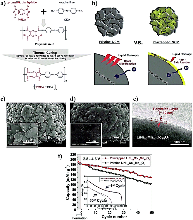 | ||
| Fig. 44 (a) Chemical structures of the four components in the precursor solution used for the in situ processing of the polyimide (PI)-based artificial PIS-CEI over the cathode by condensation polymerization. (b) Schematic illustration of a PI-wrapped NMC111 cathode. The role of the PI coating in suppressing the unwanted side reactions as well as heat generation is also depicted. SEM images of the (c) pristine and (d) PI-coated NMC111 cathode. (e) The 10 nm thick coating of a PIS-CEI layer over NMC111. (f) The superior electrochemical performance of the PI-coated NMC111-based cell over the non-coated counterpart (reproduced/adapted from ref. 518 with permission from The Royal Society of Chemistry518). | ||
In a report, a 10 nm thick layer of a PI-based PIS-CEI was in situ generated over an LCO cathode for LIB fabrication by a similar condensation polymerization reaction. The performance of the LIB cell is compared against a pristine LCO counterpart.348,349 The separately prepared self-standing PI film swollen in the LE (1 M LiPF6 in EC: EMC) exhibited an ionic conductivity of 0.15 mS cm−1 (RT). When the PI-coated LIB (LCO|LE|graphite) cell is cycled between 3 and 4.4 V, the cell delivered a specific capacity of 160 mA h g−1 (at 0.5C) with a capacity retention of 76% even after 100 cycles. In contrast, the specific capacity of PI-free cells dropped to 38% under the same conditions. It is observed that the PI coating with an average thickness of 10 nm imparts a well-balanced enhancement of the cell performance and related thermal stability of the final LIB cell. However, as the coating thickness of PI is increased, the discharge capability (C-rate) of the cells is compromised due to an undesired rise in the overall ionic and electronic resistance at the interphase. The PI-based PIS-CEI layer is reported to reduce exothermic side reactions, which underlines the efficacy of the thermally stabilized electrode|electrolyte interface and interphase (Fig. 44b).518Fig. 44c and d present the SEM images of the pristine and PI-coated NMC-111 electrodes, respectively. The 10 nm thick conformal surface coating of PI over NMC111 is evident from Fig. 44e; additionally, Fig. 44f confirms the superiority of the electrochemical performance of the PI-coated LIB (NMC111|LE|graphite) cell against a PI non-coated NMC111 electrode-based LIB cell. The authors have also attempted to produce a composite of PI and carbon black to modify the LCO surface, which results in improved electrical conductivity of the surface coating by providing high rate capability during the long-term galvanostatic charge–discharge cycling.519 Similarly, PI coated (10 nm thick) high-voltage spinel LNMO cathodes are used for the fabrication of LIB cells and cycled at RT (3.5–5 V) and 55 °C (3.5–4.9 V).520 At RT, both the pristine and PI-LNMO based cells exhibited almost similar cycling performance. However, at 55 °C, the cycling behavior of PI-LNMO (98% retention, 50 cycles) is far superior to the pristine-uncoated (83% retention, 50 cycles) counterpart. Apart from reducing interfacial exothermic reactions between the charged LNMO and the LE, the PI coating prevents Mn2+ dissolution from LNMO. The same method is adopted for high-voltage vanadium doped LNMO cathodes, and exciting characteristics similar to the above materials are also demonstrated.521 In conclusion, all the aforementioned reports suggest that the PI-based PIS-CEI layer synergistically contributes to enhanced cycling performance. It can also be elucidated that the coating of electrode particles by judiciously selected monomers by condensation polymerization can be an alternative approach over the existing costly and difficult to upscale processes such as pyrolysis, atomic layer coating, or even sputtering techniques.
6.4 Electropolymerization
A polymerization process in which a thin polymer film is formed from a monomer solution onto an electronically conducting substrate is called electropolymerization. It is usually employed in applications such as surface protection, electrode coating, electrocatalysis, electrogenerated chemiluminescence (ECL), electrochemical sensors, and electrode material preparation for energy storage and conversion devices (e.g., batteries, supercapacitors, solar cells, fuel cells, etc.).522–525 Dall’Olio et al., in 1968, reported the first example of an oxidative electropolymerization process to produce polypyrrole in water.526,527 Later in the 1980s, the reductive electropolymerization of vinyl-substituted molecules was pioneered by Abruna and co-workers.528 Currently, electropolymerization is a well-established process for the in situ deposition of polymeric films on various types of conducting surfaces.Electropolymerization is often carried out in a precursor solution supported by a three-electrode electrochemical cell (Fig. 45a),529,530 where the characteristics of the electropolymerized film depend on the type of monomer, electrolyte, electrodes, viscosity of the medium, applied potential/current, scan rate, and ultimately the electrochemical method used. A three-electrode system is generally used to control the respective electrode potential;531 however, the polymerization can also be carried out in a two-electrode assembly. Electropolymerization can be developed into a sustainable polymerization process where the energy for the polymerization can come from renewable resources. Moreover, the surface coverage and thickness of the electropolymerized films can be easily fine-tuned by selecting a suitable polymerization duration, monomer type and concentration, and applied current or potential. The general drawbacks of electropolymerization include the inability to produce large molecular weight polymers as well as thick films due to the diffusion limitation of the monomers to reach the substrate electrode surface. If the electronic conductivity of the electropolymerized polymer layer is relatively low, it can affect the kinetics and continuity of the subsequent polymerization process.
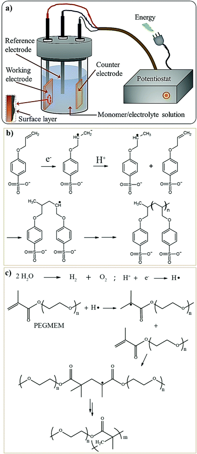 | ||
| Fig. 45 (a) Schematic representation of electropolymerization of an artificial or sacrificial protection layer over the working electrode in a standard three-electrode assembly; and the mechanism of the reductive electropolymerization of (b) a para-sulfonated allyl phenyl ether monomer in DMSO medium (reproduced/adapted from ref. 540 with permission from Elsevier, Copyright 2017540) and (c) PEGMEM in an aqueous medium.545 | ||
Galvanostatic, potentiodynamic, or potentiostatic techniques can be used for the electrochemical polymerization process.529,532,533 The galvanostatic approach uses a constant current, hence allowing greater control over the thickness of the electropolymerized film in addition to maintaining a constant polymerization rate. In the potentiostatic method, a constant potential is applied, where the control over the rate of polymerization is often lost. However, if the applied potential is controlled precisely, optimum morphological features of the polymer film can be achieved even with the potentiostatic technique.494 In the case of the potentiodynamic approach, the potential of the electrode is varied at a selected scan-rate over a wide potential window, which is often used for the detailed investigation of the polymerization mechanism.494 Generally, electropolymerization can progress through oxidation (anodic) or reduction (cathodic) pathways.533,534 In the case of oxidative electropolymerization, the monomer unit turns into a radical cation, whereas, in the case of reductive polymerization, a radical anion is formed. Such a chain initiation process occurring through an electrochemical event is often called electro-initiation. The formation of these radical anions and cations is followed by polymer chain propagation, which can occur through an ionic or free-radical pathway. But the exact mechanism of such a propagation reaction is yet to be well-defined.535–537 Conducting polymers (important as electrode materials in EESs) are usually prepared using oxidative electropolymerization of monomers such as aniline, pyrrole, and so on. In contrast, vinyl- and allyl-functional monomers (important as PEs) are mostly polymerized using the reductive approach.538,539
For example, reductive electropolymerization of the p-sulfonated (allyl phenyl ether) monomer from a nonaqueous LE (0.5 M LiTFSI/DMSO) is presented in Fig. 45b.540,541 Here, the first step is the formation of a radical anion followed by the addition of H+ from the reaction medium (or a trace amount of water) to form a more stable secondary free-radical. The polymerization is propagated by the reaction between the freshly generated free-radical and monomers present at the electrode surface. Vinyl monomers can also be polymerized in a similar fashion.542 However, in an aqueous medium, such an initiation step is not possible as the radical anion formed is terminated by the ionic end of the water.543,544 Therefore, the electropolymerization mechanism of PEGMEM from an aqueous medium is reported to be initiated by an electrochemically generated hydrogen free-radical (H˙).545 The H˙ species is formed during the reduction of H+ to H2 (Fig. 45c). In the past, reductive electropolymerization has been explored for the preparation of several types of polymer films (PAN, PMMA, polybutadiene, polystyrene, etc.) in aqueous and nonaqueous media.544,546–548 Ultimately, the in situ process using the electropolymerization technique can be important in the context of surface protected electrodes, especially for PIS-SEI and PIS-CEI layers having desired properties. Even the direct conversion of an LE in an LB cell to a PE for the fabrication of LIPBs/LMPBs can also be envisaged.549,550 Even though the electropolymerization method is not used widely in LPBs, it has the potential to be developed into a robust tool for producing well-defined polymers integrated into LPBs during the device fabrication process.
Electrochemical reduction of unsaturated organic carbonates such as VC and vinyl ethylene carbonate (VEC) is known to form an effective polymeric SEI layer in LIBs.551 Due to the polymeric nature of the SEIs derived from VC and VEC, they can also be identified in the category of PIS-SEIs. In the conventional method, the reduction reaction that occurs during the formation cycle of the battery cell is often tricky to control externally.407,550,552 To overcome the afore-noted difficulty, poly-VC-based PIS-SEI layers are prepared on the anode surface by a novel method involving the controlled and timely release of VC into the electrolyte solution and the diffusion of these VC molecules to the anode surface using VC-microcapsules.553Fig. 46a presents the scheme of the process in which the VC-microcapsules release a small amount of VC into the LE in the first charging cycle, which subsequently takes part in forming PIS-SEI layers by the reductive electropolymerization process. During successive cycles, the VC-microcapsules continue with the slow release of VC by maintaining an optimum VC concentration corresponding to 5 wt% VC. The VC-microcapsule technique is an autonomous strategy involving the temperature- and concentration-controlled diffusion of VC to the electrode surface. As compared to the conventional method of simply adding VC in the electrolyte as an additive, the VC-microcapsule technique can be controlled externally, enhancing the durability and rate performance of the LIB (NCA|LE|graphite) full cells (Fig. 46b). The scheme depicting the general pathway and electro-reduction of VC is presented in Fig. 46c, where poly-VC (product A) is generally accepted to be a major component in the interphases at both the graphite anode and LCO cathode.88,409,554
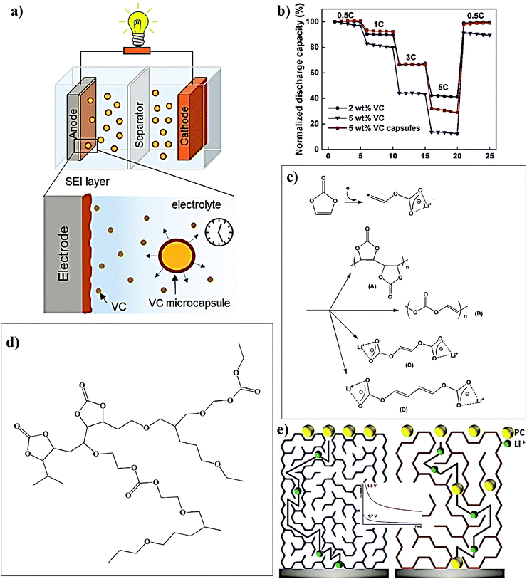 | ||
| Fig. 46 (a) Schematic of the microcapsule-based release of the VC additive in an LIB and the in situ electroreduction to the PIS-SEI surface protection layer at the anode electrode surface; (b) the improved rate-capability of an LIB achieved through the microcapsule technique over the conventional approach of adding VC as an additive in an LE (reproduced/adapted from ref. 553 with permission from American Chemical Society, Copyright 2017553); (c) the possible reaction products of the electro-reduction of VC molecules;88,409,554 (d) the plausible 3D branched polymeric product formed by the electro-reduction of organic carbonate solvents (EC, PC, etc.), which becomes part of the SEI (reproduced/adapted from ref. 88 with permission from American Chemical Society, Copyright 201488); and (e) representation of PC non-permeable (left side) and permeable (right side) polymeric components formed by the electro-reduction of PC at 1.0 V (equilibrium reduction potential) and 1.7 V (UPE) vs. Li|Li+ (reproduced/adapted from ref. 357 with permission from Elsevier, Copyright 2016.357 Distributed under a Creative Commons Attribution License International 4.0 (CC BY 4.0) (https://creativecommons.org/licenses/by/4.0/)). | ||
Apart from electrolyte additives like VC or VEC, state-of-the-art carbonate solvents such as PC can also undergo electrochemical reduction so that polycarbonate-based PIS-SEI layers can be expected. However, the compositions of the SEI formed by the electro-reduction of PC and other organic carbonate solvents are highly debated.88 Several early reports related to SEIs suggest that the PC reduction leads to the formation of a semicarbonate known as lithium ethylene dicarbonate ((CH2OCO2Li)2, LEDC) by ROP of PC without oligomeric or polymeric products. However, several recent studies using advanced mass-spectrometry techniques (thermogravimetric mass-spectrometry (TG-MS), MALDI, etc.) have convincingly proved (m/z ratio of 3000 and 1500 from PC and EC/DMC, respectively) the polymeric nature of the electrochemical reduction products of organic carbonate solvents.356,555–557 It is even claimed that the polymeric components evolved from the organic carbonates are 3D branched network polymers (see Fig. 46d).88 To understand the fundamental characteristics of the PIS-SEI formed by the reduction of PC solvent in an LE-LMB, Kasmaee et al. conducted chronoamperometry studies at different applied potentials of 1, 1.1, and 1.7 V vs. Li|Li+.357 The underpotential electropolymerization (UPE is electropolymerization happening at a lower negative potential than the equilibrium reduction potential of the monomer) of PC occurring at 1.7 V vs. Li|Li+ can ensure the formation of an efficient PIS-SEI layer, which is PC impermeable, compact, electrically insulating, and Li+-ion conducting. Besides, the UPE processed PIS-SEI constitutes interconnected long polymer chains extended over the electrode surface. This study concludes that the polymerization kinetics play a critical role in controlling the properties of the PIS-SEI. The slow polymerization initiation rate under UPE conditions provides sufficient time for the formation of longer polymer chains. However, close to the equilibrium reduction potential (1 and 1.1 V vs. Li|Li+), the PC reduction rate prevails, leading to an inferior SEI composed of short and disjointed polymer domains with high PC permeability. Since the diffusion coefficient of PC within the UPE processed PIS-SEI is very low, it can provide superior Li-metal protection compared to the PIS-SEI formed at the equilibrium reduction potential having a high PC diffusion coefficient. The schematic illustration of the PC permeable and impermeable polymer chains formed over the Li-metal electrode surface at different electrode potentials (red-colored chains indicate the equilibrium reduction of PC at 1.0 V vs. Li|Li+ and blue under UPE conditions of 1.7 V vs. Li|Li+) is presented in Fig. 46e.
Like in the case of LBs, the SEI is an essential component in other battery chemistries as well, especially in sodium metal anode-based Li-free alternative batteries. Even though slightly out of context considering the focus of the review, the work by Wei et al. regarding Na-metal batteries is interesting as it can find application in LMBs as well. They proposed the in situ reductive electropolymerization of allyl-/vinyl-functionalized ionic liquid monomers to realize an artificial PIS-SEI layer over a Na-metal anode.558 Here, the unsaturated ionic liquid undergoes reductive electro-initiation to generate a radical anion (Fig. 47a), which can propagate the growth of the polymer chain. Three different ionic liquid monomers are investigated for electropolymerization and it is reported that the PIS-SEI formed over the anode is influenced by the molecular structure of the ionic liquid monomer used. For instance, the mono-functional 1-allyl-3-methylimidazolium perchlorate (AMIM) monomer results in an oligomeric PIS-SEI, whereas the bi-functional monomers 1,3-diallyl imidazolium perchlorate (DAIM) and 1-allyl-3-vinyl imidazolium perchlorate (AVIM) produce high molecular weight polymers. Among the AVIM and DAIM molecules, the former is a highly reactive species due to the presence of an sp2 hybridized vinyl group, which leads to a denser polymer layer. However, the allyl carbon in DAIM imparts internal plasticization, and the formed polymer layer is soft and rubbery. Therefore, the DAIM-based PIS-SEI is employed for further investigation. Both Na3V2(PO4)3|LE|Na and S|LE|Na cells are fabricated using the in situ electropolymerized DAIM-based PIS-SEI over the metallic anode from an LE (20 wt% DAIM in 1 M NaClO4 in EC:PC). In the case of the Na3V2(PO4)3|LE|Na cell, the PIS-SEI protection helps in retaining above 90% of the initial specific capacity (≈105 mA h g−1) over 160 cycles, whereas, in the cell without the PIS-SEI coating, the capacity drastically dropped below 50% in just 20 cycles (Fig. 47b). Additionally, similar performance improvement is also observed in PIS-SEI-protected S|LE|Na cells over the non-protected counterpart (Fig. 47c).
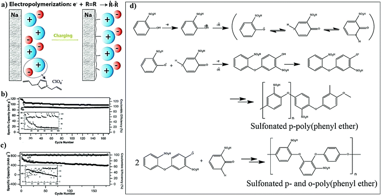 | ||
| Fig. 47 (a) Schematic representation of the formation of a DAIM ionic liquid-derived PIS-SEI over Na-metal by reductive electropolymerization. Cycling performance of the PIS-layer protected (b) Na3V2(PO4)3|LE|Na and (c) S|LE|Na cells. In the inset (b and c), the cycling stability of the unprotected cells is also displayed (reproduced/adapted from ref. 558 with permission from John Wiley and Sons, Copyright 2017558). (d) Mechanism of oxidative electropolymerization of the phenyl monomer, namely o-hydroxybenzenesulfonate (o-HBS) (reproduced/adapted from ref. 567 with permission from John Wiley and Sons, Copyright 2016567). | ||
Electropolymerization as a tool for the direct conversion of 1,3-DOL present in an LE to a poly-DOL-based artificial PIS-CEI that can protect the high-voltage LNMO cathode and the high-capacity sulfur cathode was demonstrated by Monaca et al.559 The polymerization is carried out through chronoamperometry cycles above 4 V vs. Li|Li+ without the use of any additional initiator so that a thin PIS-CEI layer is formed over the LNMO or sulfur working electrode. The precursor used for the electropolymerization is composed of 5 m LiTFSI in 1,3-DOL (dimethyl ether as a solvent is optional). Later, the protected working electrodes are used for LE-LMB fabrication. The LNMO|LE|Li cell displayed a specific capacity of 100 mA h g−1 (1C, 26 °C, 3.5–4.8 V) with 90% capacity retention over 200 cycles. The surface protected S|LE|Li cell is found to inhibit polysulfide shuttling and displayed around 100% capacity retention over 50 cycles, which is convincingly better than the non-protected cell. In a report from Kong et al., the GPE formed from 1,3-DOL by electropolymerization is found to improve the cycling life of the LMPB (LCO|GPE|Li) cell compared to that of a test cell without 1,3-DOL.560–562 In a later published report from the same group, factors such as the cut-off voltage, current rate, and temperature influencing the electropolymerization of 1,3-DOL are emphasized.563 On fixing the cut-off potential of electropolymerization between 3 and 4.1 V vs. Li|Li+, the capacity retention is improved irrespective of the current rate, provided that the cell is kept below the onset temperature for the thermal polymerization of 1,3-DOL. However, the complete understanding of the electropolymerization mechanism of 1,3-DOL is still lacking.564
Several reports are available in the literature on the reductive electropolymerization of monomers (mainly monomers with vinyl- and allyl-functionalities) as a tool for realizing PEs, and PIS-SEI and PIS-CEI layers. However, oxidative electropolymerization for the same purpose is not very well explored. Although the oxidative polymerization of vinyl- and allyl-functional monomers governed by the formation of a radical cation is also known,542 oxidative electropolymerization reactions of phenolic monomers are mostly employed in the context of surface protection or PEs. A report by Rhodes et al. demonstrated the oxidative electropolymerization of a co-monomer solution composed of two phenolic monomers p-hydroxybenzenesulfonate (p-HBS) and 2,6-dimethylphenol (DMP) in the presence of a supporting electrolyte made of 0.3 M NaOH in methanol.565,566 As a proof of concept, oxidative electropolymerization is carried out over an indium-tin-oxide (ITO) working electrode in a three-electrode assembly [potentiostatic method, 1.5 V vs. sodium saturated calomel electrode (SSCE)]. The formed SPE can be considered as a blend electrolyte, where the poly-4-sulfonic acid-1,2-phenylene oxide (PSPO) derived from p-HBS with a sulfonate group is integrated into the poly-2,6-dimethyl-1,4-phenylene oxide (PDPO) from DMP. However, the possible formation of a covalently linked PSPO-co-PDPO copolymer is also suggested. The charge compensating Na+-ion present in the blend SPE can be easily ion-exchanged by Li+-ions to form an SIC-PE exhibiting an ionic conductivity in the order of 10−8 to 10−9 S cm−1 (RT). Considering the SPE film thickness of ≈100 nm, it can be employed as a PIS-based surface protection layer for LBs. In a recent work, the difference between the structure of polymers synthesized by electrochemical oxidative polymerization of p-HBS and its isomer o-hydroxybenzenesulfonate (o-HBS) was explained with mechanistic details by Braglia et al.567 It is observed that o-HBS leads to a linear polymer with faster kinetics. In contrast, p-HBS follows slower polymerization kinetics with the formation of a sterically hindered polymer network. The detailed oxidative polymerization mechanism of o-HBS is presented in Fig. 47d. However, the applicability of any of these polymers is yet to be demonstrated in ex situ or in situ processed LB full cells.
In summary, Sections 6.1 to 6.4 primarily discuss the anionic, cationic, condensation, and electropolymerization methods adopted for the in situ processing of LIPB/LMPB cells and surface protection of electrodes. Depending on the type of monomers and available reaction conditions, one of these methods can be used to fabricate LB cells. All these methods are suitable for producing GPEs, SPEs, and PIS-interphases. Anionic and cationic polymerization can occur even in the absence of any additional initiators, as the Li-metal or even salt can initiate the polymerization reaction. For instance, the Li-metal induced anionic polymerization of cyanoacrylate monomers is suitable for the surface protection of the Li-metal anode in LE-LMBs and LMPBs. The temperature dependency of anionic polymerization of VC can be ingenuously used for the in situ fabrication of smart LMPB cells, which possess a self-shutdown mechanism. Cationic polymerization is suitable for ROP reactions. For instance, the CROP of 1,3-DOL provides the opportunity for direct conversion of an LE to a PE or even a conformal electrode protection layer-based on poly-DOL. Other types of cyclic monomers, such as epoxides, are also suitable candidates for CROP. In Tables 6 and 7, the reports on anionic and cationic in situ polymerization processes used for LB applications are compiled and summarized.
| Monomer/oligomer | Electrolyte/salt | Initiation | Ionic conductivity | Cell | Operating voltage range | Capacity | Capacity retention | Ref. |
|---|---|---|---|---|---|---|---|---|
*![[thin space (1/6-em)]](https://www.rsc.org/images/entities/char_2009.gif) Separator assisted. # Separator assisted. #![[thin space (1/6-em)]](https://www.rsc.org/images/entities/char_2009.gif) Direct deposition. &PIS-interphase. Direct deposition. &PIS-interphase. |
||||||||
| ECA# | 4 M LiClO4 in EC:DMC | Electron transfer from Li-metal | 2.7 mS cm−1 at RT | LFP|GPE|Li | 2.5–4 V | 140 mA h g−1 (1C, RT) | 90%, 100 cycles, 1C | 481 |
| ECA& | 1 M LiPF6 in EC:DMC | Moisture | — | LNMO|LE|Li | 3.5–5 V | ≈122 mA h g−1 (1C, RT) | 92%, 100 cycles, 1C | 346 |
| ECA& | 1 M LiPF6 EC:DMC | Hydroxyl group on Li-metal surface | — | LFP|LE|Li | 2.5–4 V | 150 mA h g−1 (2C, RT) | 100%, 500 cycles, 2C | 488 |
| VC* | LiI | Lithium iodoalkoxide | 1.8 mS cm−1 at 25 °C | LTO|GPE|Li | 1–2 V | ≈150 mA h g−1 (1C, RT) | 50%, 700 cycles, 1C | 489 |
| Monomer/oligomer | Electrolyte/salt/plasticizer | Initiator species | Ionic conductivity | Cell | Operating voltage range | Capacity | Capacity retention | Ref. |
|---|---|---|---|---|---|---|---|---|
*![[thin space (1/6-em)]](https://www.rsc.org/images/entities/char_2009.gif) Separator assisted. $ Separator assisted. $![[thin space (1/6-em)]](https://www.rsc.org/images/entities/char_2009.gif) Multi-layer approach. Multi-layer approach. |
||||||||
| TEGDVE$ | 1 M LiBETI in EC:DEC | H+BF4− | 1 mS cm−1 at 30 °C | LCO|GPE|Li | 3–4.3 V | 150 mA h g−1 (15 mA g−1, 30 °C) | — | 499 |
| PVA-CN* | 1 M LiPF6 in EC:DMC:EMC | H+(PF5OH)− | — | LCO|GPE|graphite | 2–4.4 V | >1900 mA h (0.2C, 25 °C) | >80%, 50 cycles, 0.2C | 500 |
| PVA-CN* | LiTFSI, SN | H+(PF5OH)− | 2.37 mS cm−1 at 25 °C | LFP|GPE|Li | 2.4–4.2 V | 155 mA h g−1 (0.1C, 25 °C) | 96.7%, 100 cycles, 0.1C | 501 |
| PEGDE* | LiTFSI | H+(BF3OH)− | 0.09 mS cm−1 at RT | LFP|SPE|Li | 2.5–4 V | ≈115 mA h g−1 (0.1C, 25 °C) | 74%, 100 cycles, 0.1C | 504 |
| Siloxane epoxide with PVS* | 1 M LiPF6 in EC:DMC | H+(PF5OH)− | 11 mS cm−1 at 30 °C | LCO|GPE|graphite | 2.8–4.2 V | 133 mA h g−1 (0.1C, 30 °C) | ≈98%, 200 cycles, 0.1C | 510 |
| 1,3-DOL* | LiPF6, LiTFSI | H+(PF5OH) − | 3.8 mS cm−1 at RT | S|GPE|Li | 1.8–3 V | 1010 mA h g−1 (0.5C, RT) | 50%, 500 cycles | 511 |
| 1.3-DOL* | LiTFSI | Al(OTf)3 | 1 mS cm−1 at RT | LFP|SPE|Li | 2.5–4 V | 100 mA h g−1 (1C, RT) | ≈75%, 700 cycles, 1C | 334 |
Besides ionic polymerization methods, a few reports address the in situ processing of PIS-interphase layers using condensation polymerization and electropolymerization methods. These two techniques are mainly employed for surface protection, either at the anode or cathode. Condensation polymerization is adopted primarily for forming artificial protective coatings at the cathode, which act as a PIS-CEI layer. In contrast, electropolymerization reactions have been employed for the preparation of both PIS-SEI and PIS-CEI coatings. Therefore, these two methods are suitable and should be further explored for developing polymeric interphases with excellent physicochemical and electrochemical characteristics. Indeed, such judiciously prepared layers will enable the use of high-voltage cathodes for LBs and avoid some of the disadvantages related to oxidation or reduction stability of commonly used polymer hosts. The thin layer coating on high-voltage cathodes such as LCO, LMNO, and NMC111 is proven to reduce the exothermic reactions and Mn2+-dissolution in the interface between the LE and electrode, improving the cycling stability. Hence, by using these polymerization techniques, safer LIBs can be built. Like ionic polymerization, electropolymerization can be carried out without the presence of additional initiators. However, fully-fledged utilization of the electropolymerization method for the in situ processing is rarely attempted for conventional LMPB/LIPB cell fabrication. Electropolymerization requires special attention as polymeric SEI/CEI (PIS-SEI/PIS-CEI) layer formation is an inherent and essential phenomenon in all types of LBs. In recent times, electropolymerization has evolved as an exciting method for customized LB (e.g. microbatteries) fabrication, as discussed in the following sections. In the case of microbatteries, their small size is an added advantage that allows electrochemically polymerized conformal coatings of PIS itself to effectively act as a separator and prevent individual electrodes from coming into contact.
7. Potential scope of the in situ process in customized LPB fabrication
In the previous sections, the adoption of the in situ process for the fabrication of conventional LPB cells is thoroughly covered. The potential of the in situ process is envisaged to have an imminent impact on other customized cell designs such as lithium microbatteries (mLBs), flexible and wire-shaped LBs, and even those LBs with complex geometries. Such customized battery designs are significant in micro, flexible, and portable electronics to be integrated with miniature devices such as medical aids, sensors, actuators, and other internet-connected devices, which constitute the futuristic Internet of Things (IoTs).568–571 In this context, the following section provides an overview of several attempts for fabricating customized LBs making use of the in situ polymerization process.7.1 Microbattery fabrication using the in situ process
The working principles of mLBs and conventional LBs are the same. Still, the size of an mLB is extremely small and generally accepted to be ≤0.1 cm3.572 Reduction in the size of state-of-the-art LBs demands updated manufacturing methods with alternative electrolyte designs to overcome the risks related to LE leakage and other safety issues. SSEs are ideal for such devices, where PEs are expected to make a huge impact. To cope with the architectural flexibility of such devices, shape deformable PEs are indeed inevitable.279,573,574 Despite significant advancement in physical and chemical methods for mLB fabrication such as 3D-printing, thin-film lithography, physical and chemical vapor deposition, thermal evaporation, atomic layer deposition, laser printing, and sol–gel methods, the limited areal/volumetric capacity, energy density, and power density offered by mLBs remain a considerable challenge.368,574,575 A summary of the different types of commonly used mLB designs is presented in Fig. 48a–d.281 Generally, the architecture of the microelectrode in mLBs can be either 2D or 3D. Using 2D- and 3D-microelectrodes, mLBs can be fabricated in both in-plane and stacked geometries.281 The recent trend in mLB fabrication is the patterning of interdigitated microelectrodes on a single plane and these are called interdigitated in-plane mLBs. Detailed descriptions of the type of mLBs and the different electrode configurations are available elsewhere.281,574,576,577 In the case of an interdigitated cell architecture, the specific capacity, energy/power density, etc. can be improved by increasing the height of the deposited electrodes, which facilitates an increased mass-loading of the active materials.578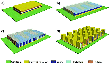 | ||
| Fig. 48 Schematic representation of the four commonly used mLB configurations: (a) 2D stacked, (b) 2D in-plane, (c) 3D in-plane, and (d) 3D stacked (reproduced/adapted from ref. 281 with permission from John Wiley and Sons, Copyright 2019281). | ||
Like conventional LBs, the electrode|electrolyte interface/interphase significantly influences the performance metrics of mLBs. For instance, the infiltration of an LE and wetting of the interiors in 3D-microelectrodes is relatively easy and efficient. However, LEs are not a suitable choice for mLBs due to the risk of leakage and the requirement of stringent packaging norms. Therefore, the adoption of the in situ process, which can ensure efficient electrode|electrolyte interface/interphase, and maximum active material utilization, will be beneficial while fabricating mLBs. Since the integration of different components (electrode and electrolyte) of mLB cells in the micron-dimension is challenging, the direct generation of conformal and ultra-thin PE layers (can be considered as PIS layers due to the sleek nature of the PE in mLBs) over microelectrode arrays by the in situ process can leverage certain manufacturing/fabrication advantages. In the case of conventional LBs, the role of PIS layers is to protect the electrode surface, where the luxury of an additional separator soaked in an LE or a PE film provides the physical separation between the anode and cathode. However, in mLBs, the PIS should be ideally capable enough to simultaneously play the role of a separator and an electrolyte since the use of an external separator or PE film is not feasible due to the small dimension and the interdigitated configuration of most mLBs.
Brandell et al. have synthesized and explored several UV polymerized electrolytes for mLB applications. In one of the reports, a thin SPE is in situ processed (direct deposition) over the LFP electrode during mLB fabrication.580,583,584 They prepared a precursor consisting of a cross-linker (poly(propylene oxide) diacrylate (PPOD)), a surfactant polyetheramine (glyceryl poly(oxypropylene) (PEA), LiTFSI (Li![[thin space (1/6-em)]](https://www.rsc.org/images/entities/char_2009.gif) :
:![[thin space (1/6-em)]](https://www.rsc.org/images/entities/char_2009.gif) O ratio of 1
O ratio of 1![[thin space (1/6-em)]](https://www.rsc.org/images/entities/char_2009.gif) :
:![[thin space (1/6-em)]](https://www.rsc.org/images/entities/char_2009.gif) 20), and a photoinitiator (Irgacure 2022) in ethanol (ethanol is evaporated during SPE processing step). PEA is a molecule with surfactant properties, which can be considered an additive/plasticizer capable of inducing hydrogen bonding interactions with the oxygen moieties present in the electrode particles. These interactions help in ensuring the effective wetting of the electrode by the precursor. Although not mentioned, it is possible that the PEA molecule can become part of the polymer host by an aza-Michael addition reaction.579,585 An example of the aza-Michael addition reaction between amine and acrylate in the mixture is presented in Fig. 49a.579 This is a multi-step process, which involves the formation of an aza-Michael network that can undergo subsequent cross-linking polymerization on UV-irradiation. The heat generated during the UV irradiation would be sufficient to catalyze the aza-Michael reaction. This method of cross-linking polymerization is industrially important and is generally used to prepare thermosets. The UV-cured SPE prepared by Brandell et al. comprises a conformal coating (1–3 μm thick) over the LFP surface. The SPE film exhibits an ionic conductivity and oxidative stability of 0.00345 mS cm−1 and 5.2 V vs. Li|Li+, respectively (30 °C). It is worth noting that due to the short transport distances in mLBs, the low ionic conductivity value compared to conventional PEs does not significantly influence the internal cell resistance.327 At 60 °C, a specific capacity of 120 mA h g−1 is obtained with stable cycling over 30 cycles for the LFP|SPE|Li cell. The same SPE prepared over 3D-Cu2Sb microelectrodes is also illustrated in Fig. 49b–d, demonstrating the possibility of obtaining a conformal coating essential for mLB applications.580 The 3D-Cu2Sb-based mLB displays a higher discharge capacity than the 2D-Cu2Sb counterpart due to the availability of more surface area within the 3D microelectrode architecture, which is accessible by the in situ generated SPE. The bi-functional oligomer species synthesized by modification of the PEA molecule by substituting the methacrylate monomer is also reported as a potential candidate for the in situ processing of mLBs.581 The PEA-methacrylate monomer is prepared by the simple Michael-addition reaction, unlike the aza-Michael reaction in the earlier case. The reaction between PEA and methacrylic anhydride (MAA) in the presence of triethylamine (TEA), leading to the formation of methacrylate substituted PEA, is displayed in Fig. 49e. Due to the possible presence of more than one methacrylate end group in the substituted PEA, the use of additional cross-linker monomers such as PPOD is avoided here. Ultimately, the authors claim that the substituted PEA performs better than the unsubstituted counterpart combined with LFP electrodes.
20), and a photoinitiator (Irgacure 2022) in ethanol (ethanol is evaporated during SPE processing step). PEA is a molecule with surfactant properties, which can be considered an additive/plasticizer capable of inducing hydrogen bonding interactions with the oxygen moieties present in the electrode particles. These interactions help in ensuring the effective wetting of the electrode by the precursor. Although not mentioned, it is possible that the PEA molecule can become part of the polymer host by an aza-Michael addition reaction.579,585 An example of the aza-Michael addition reaction between amine and acrylate in the mixture is presented in Fig. 49a.579 This is a multi-step process, which involves the formation of an aza-Michael network that can undergo subsequent cross-linking polymerization on UV-irradiation. The heat generated during the UV irradiation would be sufficient to catalyze the aza-Michael reaction. This method of cross-linking polymerization is industrially important and is generally used to prepare thermosets. The UV-cured SPE prepared by Brandell et al. comprises a conformal coating (1–3 μm thick) over the LFP surface. The SPE film exhibits an ionic conductivity and oxidative stability of 0.00345 mS cm−1 and 5.2 V vs. Li|Li+, respectively (30 °C). It is worth noting that due to the short transport distances in mLBs, the low ionic conductivity value compared to conventional PEs does not significantly influence the internal cell resistance.327 At 60 °C, a specific capacity of 120 mA h g−1 is obtained with stable cycling over 30 cycles for the LFP|SPE|Li cell. The same SPE prepared over 3D-Cu2Sb microelectrodes is also illustrated in Fig. 49b–d, demonstrating the possibility of obtaining a conformal coating essential for mLB applications.580 The 3D-Cu2Sb-based mLB displays a higher discharge capacity than the 2D-Cu2Sb counterpart due to the availability of more surface area within the 3D microelectrode architecture, which is accessible by the in situ generated SPE. The bi-functional oligomer species synthesized by modification of the PEA molecule by substituting the methacrylate monomer is also reported as a potential candidate for the in situ processing of mLBs.581 The PEA-methacrylate monomer is prepared by the simple Michael-addition reaction, unlike the aza-Michael reaction in the earlier case. The reaction between PEA and methacrylic anhydride (MAA) in the presence of triethylamine (TEA), leading to the formation of methacrylate substituted PEA, is displayed in Fig. 49e. Due to the possible presence of more than one methacrylate end group in the substituted PEA, the use of additional cross-linker monomers such as PPOD is avoided here. Ultimately, the authors claim that the substituted PEA performs better than the unsubstituted counterpart combined with LFP electrodes.
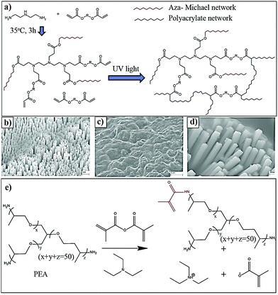 | ||
| Fig. 49 (a) Thermally triggered aza-Michael addition reaction occurring between amine and acrylate molecules. The aza-Michael product on UV curing produces a cross-linked polymer network (reproduced/adapted from ref. 579 with permission from The Royal Society of Chemistry579). SEM image of the (b) 3D Cu-pillar microelectrodes and (c and d) the 3D Cu-pillar microelectrode surface after the in situ polymerization process at two different magnifications (reproduced/adapted from ref. 580 with permission from Elsevier, Copyright 2011580). (e) Synthetic modification of PEA to PEA-methacrylate (reproduced/adapted from ref. 581 with permission from Elsevier, Copyright 2013581). | ||
In situ electropolymerization is also used to generate a conformal PIS layer on the microelectrodes that can be used for mLB applications. The direct electropolymerization of PEGMEM onto nano-structured TiO2 was reported by Djenizian et al.545,586,587 To achieve this, the electropolymerization of PEGMEM in the presence of LiTFSI salt is carried out by CV onto a 3D-TiO2 nanotube electrode in an aqueous medium (three-electrode assembly where TiO2 is employed as the working electrode). The polymerization mechanism of PEGMEM is already presented in Fig. 45c. Later, an mLB is fabricated by the generation of a PE layer onto the TiO2 nanotube anode and LNMO cathode by the in situ electropolymerization process. The schematic representation of the mLB and the cross-sectional SEM images are displayed in Fig. 50a.582,588 With a prolonged number of CV cycles, it is observed that the electrodes are covered with a smooth layer of PE [Fig. 50b and c]. However, for safety reasons, an additional thin PE layer is used apart from the electropolymerized PIS layer during the full cell fabrication. Interestingly, the use of an LE is avoided here so that it can be considered as the in situ processing of an SPE-based mLB by a multi-layer approach. The in situ processed mLB is cycled in a voltage window of 1 to 3.3 V at 0.1C for 10 cycles. In the first cycle, a discharge capacity of 169 mA h g−1 (82 mA h cm−2 μm−1) is obtained, and 88% of the capacity is retained after 10 cycles. The C-rate performance of the mLB is also presented in Fig. 50d, where the mLB with pristine electrodes is found to show far inferior performance to the in situ electropolymerized counterpart.
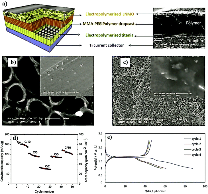 | ||
| Fig. 50 (a) Schematic representation of the mLB (LNMO|SPE|TiO2) cell fabricated by the in situ electropolymerization process. An SEM image of the cross-sectional view of the battery cell showing the various cell components is also presented. SEM images of the (b) TiO2 nanotube electrode and (c) LNMO electrode before and after (inset) the electropolymerization process. (d) C-rate performance of the LNMO|SPE|TiO2 mLB full cell (reproduced/adapted from ref. 582 with permission from Elsevier, Copyright 2017582). (e) Electrochemical performance of the in situ processed TiO2 microelectrode in the TiO2|SIC-PE|Li cell. (reproduced/adapted from ref. 540 with permission from Elsevier, Copyright 2017540). | ||
Ferrari and Braglia et al. extended the in situ electro-polymerization strategies for realizing SIC-PEs for potential application in mLBs.540,589 The electro-polymerization of p-sulfonated allyl phenyl ether is achieved by both CV and chronoamperometry techniques. A precursor consisting of the monomer and 0.5 M LiTFSI salt is prepared in DMSO solvent. TiO2 nanotubes, platinum, and Ag|AgCl are used as the working, counter and reference electrodes, respectively, in a standard three-electrode cell assembly. The mechanism of electropolymerization of the p-sulfonated allyl phenyl ether is already presented in Fig. 45b,540 and the SEM images confirmed that the thickness of the PE layer is 300 nm. Here also, an additional separator is used during the cell fabrication to avoid any possible cell failure due to short-circuit. The cycling of the TiO2|SIC-PE|Li mLB half-cell is carried out at 25 °C (1–3 V) (Fig. 50e), which exhibited a high areal energy density (65 μW h cm−2 μm−1) and power density (90 μW h cm−2 μm−1). Therefore, from the electrochemical performance point of view, these results are claimed to be the best among the results reported in the recent literature on mLBs.
7.2 Printable LBs
User-tailored devices such as shape-conformable portable devices, wireless gadgets, and roll up displays are growing in demand day by day. To bring them to fully-fledged utilization, shape conformable and miniaturized energy storage devices are equally important. To fabricate such energy storage devices, flexible and readily deformable PEs are inevitable.570,590–593 The in situ process has the potential to be integrated with sophisticated printing techniques for the fabrication of both conventional and customizable LBs. In any printing technique, a digitally designed pattern is inscribed on a substrate of interest. The most important prerequisite for successful printing is a suitable ink with reasonable viscosity characteristics. Depending on the end-user application, tailor-made inks with desirable properties can be prepared and used for the printing process. Once suitable inks are available with electrode and electrolyte components, sophisticated printing techniques such as 3D-printing, inkjet printing, laser printing, screen-printing (stencil printing), spray printing, and so on can be employed for LB fabrication.594 In this section, a few reports in which the free-radical polymerization assisted in situ process combined with advanced printing techniques is used for the fabrication of customized LBs are included.463,481,595,596 Considering the industrial importance, more emphasis is given to 3D-printed LBs, with few reports on screen-printed and stencil printed LBs. Soon, more studies on printable LBs are expected to be evolved by employing suitable printing techniques due to the increased interest in wearable, portable, and flexible electronics, IoT, etc.In the case of 3D-printing, inks and their components are very important. Different types of inks can be used depending on the end application, which is often a solution of polymer, fillers, and additives in a suitable solvent or solvent mixture. In the context of LPBs, the fillers in the polymeric ink can be electrode materials and binders, which eventually form a 3D-printable electrode slurry, which can be used for electrode patterning. A polymeric ink devoid of any electrode components can be used for the 3D-printing of polymeric scaffolds and battery cell components. For the in situ processing of LPBs with a 3D-printing step, a polymerizable precursor, which is composed of reactive monomers with the electrolyte components, such as the salt, solvent, and plasticizers, can be used as the ink. Similarly, a polymerizable precursor slurry containing reactive monomers and electrode materials is useful for the patterning of battery electrodes bound by the formed polymer host. LPBs that are essentially fabricated by a 3D-printing step involving the in situ processing of a PE using a precursor (by heat/photopolymerization) within the cell assembly can be included in the category of ‘in situ-processed-3D-printed’ LPBs. The general representation of the 3D-printing of the electrode and the PE from a UV-curable electrode slurry and electrolyte ink followed by concomitant UV irradiation to realize all-3D-printed LPBs is shown in Fig. 51. Such a method is applicable for the 3D-printing of mLBs as well as conventional LPBs or even flexible LPBs with complex architectures. Direct ink writing (DIW), fused deposition modeling (FDM), stereolithography (SLA), and selective laser sintering (SLS) are a few of the commonly used 3D-printing techniques employed for both research and industrial purposes.578
For example, in a report from Sun et al., an interdigitated LFP|LE|LTO mLB is fabricated by precise patterning of polymeric inks made of electrode materials dispersed in a solution composed of ethylene glycol, glycerol, hydroxyethyl cellulose, and hydroxypropyl cellulose by 3D-printing.597 However, this work cannot be considered as an example of in situ-processed-3D-printed LPBs as an LE is used without the involvement of the in situ polymerization processing step for the full cell fabrication. Still, this work opens up the possibility of employing an additional 3D-printing step for the patterning of a PE in the space between the already 3D-printed anode and cathode scaffolds so that an in situ-processed-3D-printed LPB can be realized. Herein, the polymeric electrode slurry is used for the patterning of battery electrodes by 3D-printing. The viscosity of the ink is tuned such that it can be extruded through a nozzle. Once the 3D-scaffolds of LTO and LFP are patterned by 3D-printing, the space between the interdigitated electrodes is filled with an LE (1 M LiClO4 in EC:DMC) followed by PMMA-based cell packaging. The schematic illustration of the patterning of the 3D-microelectrodes (Fig. 52a–d) using the extrusion of polymeric inks through a 30 μm nozzle, the optical microscopy image of the nozzle (Fig. 52e), and the SEM image of the patterned interdigitated architecture (Fig. 52f) are all displayed. The charge–discharge profiles and the cycling performance of the LFP|LE|LTO full cell are also presented in Fig. 52g and h, which exhibited an areal capacity close to 1.5 mA h cm−2 (1C) while retaining more than 90% of the initial capacity over 30 cycles.
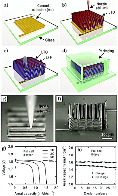 | ||
| Fig. 52 (a) Glass substrate and the current collector patterned in the interdigitated configuration; 3D-printing of the (b) LTO anode, (c) LFP cathode, and (d) PMMA-based cell package; (e) optical microscopy image of the extrusion of 3D-printable ink through the nozzle; (f) SEM image of the 3D-printed interdigitated mLB microelectrodes; (g) galvanostatic charge–discharge profiles of the 3D-printed mLB as a function of C-rate; and (h) cycling stability profile of the 3D-printed mLB (reproduced/adapted from ref. 597 with permission from John Wiley and Sons, Copyright 2013597). | ||
The 3D-printing of a PE can improve the prospects of mLBs as reported in the work of Fu et al.602 Herein, the anode and cathode inks are made by dispersing LTO and LFP nanoparticles, respectively, in a highly concentrated aqueous solution of graphene oxide (GO). The photographs of the LTO/GO and LFP/GO inks loaded in syringes are displayed in Fig. 53a, and the 3D-printed microelectrode and the interdigitated electrode assembly are presented in Fig. 53b and c, respectively. Once the 3D-printing of the anode and cathode microelectrodes and their post-processing for the conversion of GO to reduced GO (rGO) are carried out, the 3D-printing of the PE in the space between the interdigitated electrodes can be completed. For this purpose, a polymeric ink is made, which is composed of PVdF-HFP and Al2O3 nanoparticles in the NMP solvent. The sequential steps involved in the 3D-printing of the anode, cathode, and polymer electrolyte are shown in Fig. 53d. Once the polymer host is 3D-printed between the anode and cathode fingers, it can be activated by the injection of a conventional LE so that the LFP-rGO|GPE|LTO-rGO mLB full cell is ready for cycling. Fig. 53e and f present the cycling stability and charge–discharge profiles of the 3D-printed full cells, respectively. A digital image of the 3D-printed microelectrode arrays is also displayed (see Fig. 53g). Although this work demonstrates the processing of PE-based mLB cells by 3D-printing of a polymeric solution, the in situ polymerization process involving the generation of a PE from a precursor is still missing during the full cell fabrication; hence, it cannot be considered as a typical example of an in situ-processed-3D-printed LPB.
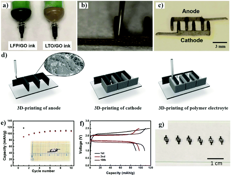 | ||
| Fig. 53 (a) LTO/GO (anode) and LFP/GO (cathode) inks loaded in syringes used for the 3D-printing of mLBs; patterning of the microelectrode (b) and the interdigitated electrode assembly (c); (d) step-wise 3D-printing of the anode, cathode, and the PE in the space between the anode and cathode fingers; (e) cycling stability and (f) galvanostatic charge–discharge profiles of the 3D-printed full cell as a function of the number of cycles; and (g) digital image of the 3D-printed interdigitated microelectrode arrays (reproduced/adapted from ref. 602 with permission from John Wiley and Sons, Copyright 2016602). | ||
In a recent report by Chen et al., the patterning of a UV-curable electrode slurry and electrolyte inks and fabrication of an mLB by microstereolithography (μSLA) are reported, which is a perfect example of an in situ-processed-3D-printed LPB.387 μSLA is a 3D-printing method in which the desired structure is fabricated layer-by-layer using a photo-polymerization process. In this work, a UV-curable resin is prepared in a bulk quantity, which is composed of PEGDA (97 wt%), Irgacure 819 (1 wt%, photo-initiator), and a photo-absorber Sudan I (2 wt%) dye. The bulk solution is later mixed with an LE (20 wt%, 1 M LiClO4 in EC:PC) to form the precursor for the GPE. Here, the photo-absorber is used for tuning the curing depth. The presence of the photo-absorber is crucial as it can avoid stray light from polymerizing the precursor providing a maximum resolution for the μSLA process. Also, the photo-absorber can absorb a certain quantity of photons and thereby control the polymerization rate, which is essential in μSLA for achieving ideal patterning.603 The schematic representation of the mLB assembly is given in Fig. 54a. The two trenches separated by the GPE is filled with the anode (LTO) and cathode (LCO) inks (a slurry made of the respective active materials dispersed in the UV-curable resin) on UV irradiation solidify by the cross-linking polymerization process. The SEM image of the GPE 3D-structure is shown in Fig. 54b and c. The specific areal discharge capacity of the cell (1.5–4.5 V) is 1.4 μA h cm−2.
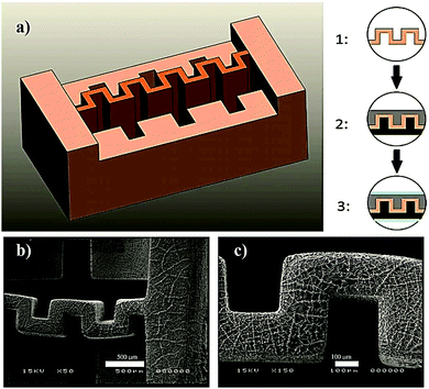 | ||
| Fig. 54 3D-printing of an mLB using the μSLA technique. (a) On the left side, the 3D-mLB architecture is presented where the anode and cathode trenches are separated by a GPE. The liquid resin used for μSLA patterning of the GPE contains the methacrylate monomer, electrolyte components, and an initiator. The assembly process for the mLB (top view) is also provided. (1) Zig-zag GPE membrane in the center, (2) filling of the UV-curable anode and cathode slurry in respective trenches, and (3) insertion of the aluminum current collector. (b) and (c) are the SEM images (top-view) of the GPE zig-zag structure (reproduced/adapted from ref. 387 with permission from IOP Publishing, Copyright 2017387). | ||
Wei et al. also reported an in situ-processed-3D-printed LIPB cell,414 and demonstrated that 3D-printing in combination with the in situ process could be extended for the production of LBs beyond mLBs. The LTO and LFP inks used in this work are made in PC solvent in the presence of LiTFSI salt and PVP binder. The presence of LiTFSI salt in the electrode ink can help in improving the inter-particle ion diffusion. A UV curable precursor containing the monomer ETPTA, PC, LiTFSI, Al2O3 nanoparticles, and HMPP is used as the ink for the preparation of a PCE by the in situ process. For the cell encapsulation, a packaging ink made of a UV-curable epoxy resin and SiO2 is used. The cell components and the steps involved in layer-by-layer 3D-printing of the customized LIPB cell are demonstrated in Fig. 55a and b, respectively. In the first step, the packaging ink is 3D-printed onto a glassy carbon substrate to form packaging walls, followed by the UV curing step. Later, the anode is 3D-printed over the glassy carbon substrate in the space between the packaging walls. Subsequently, the 3D-printing of the PCE layer over the anode is achieved by the in situ process. Later, the cathode ink is 3D-printed over the PCE layer, and the cell is closed with another glassy carbon lid. In the final step, the cell encapsulation is completed by the 3D-printing of another layer of packaging ink over the glassy carbon lid, making the cell ready to be cycled. The charge–discharge profile of the 3D-printed LIPB full cell is presented in Fig. 55c, which exhibits an areal specific capacity of 4.4 mA h cm−2 (at 0.14 mA cm−2). In the work of Yoshima et al., the in situ thermal polymerization approach is extended to the fabrication of mLB cells with LTO (anode) and LCO (cathode) electrodes in an interdigitated configuration.368 The authors are not claiming this work as an example of 3D-printed mLB fabrication anywhere in the report. However, the microinjection system with a glass-capillary used for patterning the microelectrodes is similar to the already discussed 3D-printing approaches. Once the anode and cathode are assembled in an interdigitated fashion over the substrate, the precursor consisting of 1 M LiClO4 in EC:DEC in the presence of MMA, EGDMA, and AIBN is filled in the vacancies and gaps between the anode and cathode. This is followed by a thermal curing process, which completes the in situ processing of the mLB. At 25 °C, the cell is operated between 1.5 and 2.5 V at 2C, and a discharge capacity of 270 μA h cm−2 is achieved. All the above-discussed studies are interesting as they systematically demonstrate the possible integration of 3D-printing technologies and in situ processes, which opens up new avenues for developing customized LB designs.
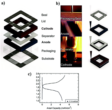 | ||
| Fig. 55 (a) The components of the fully 3D-printed customized LIPB. (b) The illustration of the 3D-printing (direct writing method) of the cell packaging, anode, PE (denoted as the separator), and cathode inks. For packaging and PE preparation, followed by the writing step, a UV curing step is used. (c) Galvanostatic charge–discharge profile of a 3D-printed LIPB full cell (reproduced/adapted from ref. 414 with permission from John Wiley and Sons, Copyright 2018414). | ||
Other than 3D-printing, in several reports of Lee et al., the screen-printing combined with the UV-light assisted in situ process is used for the fabrication of flexible LPB assemblies. Herein, one of the screen-printing techniques known as stencil printing is used, and the new class of printable LIPBs is referred to as PRISS batteries.415 Here, the PE layer and the PE embedded electrode materials are printed on substrates having complex geometries. Owing to the use of an LE (1 M LiPF6 in EC:PC) and ETPTA monomer, a cross-linked GPE can be derived by the UV curing process. The PRISS cell fabrication method is presented in Fig. 56a. In a typical procedure, a UV-curable slurry of LTO is first prepared in the precursor of the GPE. This slurry is coated over an aluminum current-collector, and a GPE embedded LTO anode is formed on UV curing. Over the anode layer, a PCE (called SCE) layer containing an Al2O3 nanofiller is formed by the in situ process from an electrolyte precursor. Subsequently, an LFP cathode layer is formed over the SCE layer by UV curing of a cathode slurry. Finally, another aluminum current-collector is placed over the LFP, and the formed LIPB cells (LFP|SCE|LTO) are hence called PRISS batteries. This work can be considered as an example of flexible LB fabrication by a multi-layer approach. The cross-sectional SEM image of the PRISS cell is presented in Fig. 56b, which clearly depicts the different cell components. At RT, the PRISS cell displayed a discharge capacity close to 160 mA h g−1 (0.05C) with cycling stability over 30 cycles (90% retention) (Fig. 56c). Similarly, photo-rechargeable portable power sources based on PRISS batteries integrated with miniaturized crystalline Si photovoltaics are also reported.604
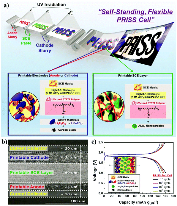 | ||
| Fig. 56 (a) Design architecture and fabrication of the PRISS battery cell by the stencil printing technique in combination with the in situ process, and the composition of the printed electrodes and SCE; (b) the SEM image of the PRISS battery cell (cross-sectional view) depicting the various components such as the printed anode, cathode, SCE, and current collectors, and their thickness; and (c) the electrochemical performance (galvanostatic charge–discharge profiles) of the PRISS battery full cell as a function of cycle number (reproduced/adapted from ref. 415 with permission from American Chemical Society, Copyright 2015415). | ||
Very recently, a screen-printing technique that is similar to the fabrication of PRISS battery cells is extended to bipolar-stacked LIPB packs (Fig. 57a).416 Two types of bipolar-stacked LIPBs possessing in-series and in-plane configurations are designed (Fig. 57a). The anode (LTO), cathode (LCO), and PE are stencil printed in a layer-by-layer manner by using the UV-curing process. The precursor for the GPE (denoted as GCE) contains ETPTA and PVdF-co-HFP in the presence of HMPP and LiPF6 in a non-flammable solvent called sebaconitrile (SBN). Depending on the number of cells connected, the bipolar-stacked LIPBs can have different voltages that vary from 2.4 V (mono cell) to 4.8 V (two cells), 7.2 V (three cells), and so on. The galvanostatic charge–discharge profiles of the printed mono cell and the bipolar-stacked LIPBs that exhibit a specific capacity close to 120 mA h g−1 (0.05C, 25 °C) are shown in Fig. 57b. Finally, the comparison of the electrochemical performance of the in-series and in-plane cells is also presented in Fig. 57c. Along with 3D-printing, screen-printing technology is also envisaged to be important for customized LB fabrication.
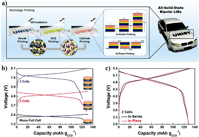 | ||
| Fig. 57 (a) Schematic illustration of the fabrication of a bipolar-stacked LIPB by the stencil printing technique in combination with the in situ process and the in-series and in-plane configurations; (b) galvanostatic charge–discharge profiles of the single-cell and the bipolar-stacked LIPBs; and (c) comparison of the electrochemical performance of the in-series and in-plane bipolar-stacked LIPB cells (reproduced/adapted from ref. 416 with permission from The Royal Society of Chemistry416). | ||
In summary, Section 7 provides an overview of the potential of the in situ process as a tool to simplify the fabrication of customized LB designs with tunable electrode|electrolyte interfaces and interphases. In the case of mLBs, a conformal coating of the PIS that can ensure effective separation between the anode and cathode electrodes is indeed necessary. The UV curing process can ensure very thin PEs possessing thicknesses between 1 and 3 μm, suitable for mLB fabrication. The in situ electropolymerization reactions are useful for realizing a thin PIS-interphase layer protecting the electrodes and for preparing thin PEs compatible with mLBs. Additionally, 3D-printing is also emerging as a unique tool to fabricate customized and geometrically complex LBs, which can be integrated with the in situ process. The technique is slowly emerging for simplifying the conventional LB processing, and, in the coming years, it can play a vital role in futuristic EES device fabrication. Apart from 3D-printing, other printing techniques such as screen-printing and stencil printing, combined with the in situ process, are also employed for flexible and customized LPB fabrication. As explained in PRISS battery cells, the integration of the in situ process with screen-printing technology can simplify flexible LIPB and LMPB processing.
8. Conclusion and future perspectives
In this review, we have overviewed the LMPB and LIPB fabrication methods based on the ex situ or in situ polymerization processes. The conventional approach of LMPB and LIPB fabrication using the ex situ processed PE film is tenuous compared to the in situ process for achieving efficient and conformal electrode|electrolyte interfaces and interphases (SEIs and CEIs). Unlike the ex situ process, the in situ process involves the generation of a PE directly within the cell assembly or over the composite electrode in line with LPB cell fabrication. The interfaces and interphases in LPBs can be modified or engineered through the in situ process by several methods such as free-radical polymerization, electropolymerization, condensation polymerization, or ionic polymerization. Until now, the in situ process has been used in LPBs to achieve enhancements such as (i) lowering the charge transfer resistance at the interface, (ii) reducing volume expansion and pulverization of metal oxide-based electrode particles during charge–discharge cycling, (iii) improving active material utilization, (iv) decreasing transition metal dissolution, (v) thin and separator free electrolyte fabrication for microbatteries, (vi) single-step 3D-printing of LPBs, (vii) protection of the electrode by artificially and sacrificially created conformal interphase layers, and (viii) multi-layer processing of LIPB and LMPB cells. Most of the literature reports regarding the in situ processing of LPBs are focused on GPEs, where the presence of a liquid constituent may compromise their mechanical stability and non-flammability, and such shortcomings can only be addressed through all-solid-state systems, in particular using SPEs. Hence a more focused approach towards developing superior SPEs that are in situ processable is necessary for the realization of industrial-scale production of futuristic LPBs.Most of the work in the field of LPBs using the in situ polymerization process is carried out on LFP-based electrodes, and the voltage range in which these electrolytes are working is mostly below 4 V. Besides, most of the reported cells have an areal capacity below 1.0 mA h cm−2. However, futuristic battery systems are focused on high-voltage cathode materials due to the demand for high energy and power. Indeed, the recent trend is to employ nickel- and Li-rich cathode materials (e.g., NMC622, NMC 811, NCA, etc.). In all these cases, the critical factor that limits the compatibility of PEs with high-voltage cathodes is their low oxidative stability and dendrite resistance capabilities. In general, high oxidative stability values are claimed in many literature reports for PEs (≥4.5 V vs. Li|Li+) in electrodes such as Pt, stainless steel, and Al. However, when Ni-, Mn-, or Co-based cathode materials are used, accelerated oxidative degradation or inferior long-term cyclability is witnessed. Additionally, the undesirable side reactions at the interfaces should be appropriately addressed to achieve the best performance in high-voltage battery systems. Hence, a real understanding of the oxidative stability values along with new characterization methods is required for the further development of PEs that are in situ processable for high power and energy-dense LMPBs/LIPBs.
To further improve the in situ polymerization process, the know-how of organic chemistry, polymer chemistry, physical chemistry, and electrochemistry should contribute equally. This multi- and inter-disciplinary approach can help in designing new polymerizable monomers and oligomers, which can ensure a better chemical and electrochemical stability in their pristine form and post-polymerized form. Along with the plethora of available studies on acrylate and methacrylate monomers/oligomers, other functionalities such as allyl and vinyl should also be investigated in the in situ free-radical polymerization process. Modification of acrylate and other monomers with hetero-functionalities (P, Si, F, etc.) is rarely explored for the in situ process and should be considered in future works. Besides, recent reports on in situ ionic polymerization suggest that it can evolve as a competitor to the free-radical methods. The potential of electropolymerization to ensure conformal coating of PE layers and artificial interphases should be exploited well for LIPBs and LMPBs. Especially in microbatteries, the electropolymerization method can have an imminent impact since it can effectively control the thickness of the PE in the nano-structured microelectrodes.
The future of PE-based energy storage is challenging, and we must address essential concerns such as:
1. Lack of fundamental studies on electrochemical reduction and oxidation of polymers, salts, and plasticizers to understand the stability and durability of LMPBs/LIPBs.
a. Investigating LPB cells with areal capacity above 1.0 mA h cm−2 and exploring their practicality in high energy and high power applications.
b. PE-based battery cells need to be investigated using accelerated testing models to understand the degradation processes via post-mortem analysis; however, present cycling studies are performed at low C-rates and are time-consuming.
c. The role of conductive carbon as an electrode additive in PE degradation during long-term cycling must be clarified. In situ and ex situ analytical tools need to be adapted/developed to elucidate the degradation mechanism in addition to exploring alternate conductivity enhancing additives and binders that are often polymer-based.
2. The behaviors of PEs against thin Li-metal (<50 μm) and the native oxide layers on Li-metal, which play a vital role during the charge–discharge cycles or in dendrite resistance, must be understood. Hence the fundamental understanding of the interface and interphase with Li-metal will be crucial for the development of true solid-state LPBs. Besides, the scope of in situ processing in the context of advanced anode-free LPBs should also be addressed in future works.
3. The significant concerns related to SPEs are also valid for GPEs, even though the performance of a GPE in a Li-ion/Li-metal cell is primarily dominated by the added plasticizer. Hence, the role of the polymer host and its peculiarities in the electrochemical performance are least investigated; however, a detailed study is necessary to understand the role of individual polymer hosts that have been employed in GPEs until now.
4. The interface engineering against thick electrodes, particularly at the cathode of an LMPB (both the anode and the cathode in the case of an LIPB), might be extensively influenced by the in situ and ex situ process; hence, a detailed investigation is necessary to understand the reactions taking place at the interface as the maximum surface of the active materials is exposed to the PEs due to the in situ process. Thus, new approaches and engineering strategies must be developed.
5. Controlling the electrical and ionic conduction in composite electrodes, and the ion and current flux at the Li-metal anode of an LMPB is required to avoid HSAL growth.
6. The approaches that are yet to be widely incorporated in PE research are:
a. Design and use of new polymer architectures and plasticizer chemistries to stabilize the PE during the continuous redox processes occurring at the electrodes.
b. A tailor-made passivation layer at the anode and cathode, and the engineering of artificial SEIs and CEIs should be encouraged in LPBs. The use of separately engineered and integrated passivation layers, followed by multi-layer cell assembly processes, should be adopted. The in situ polymerization process is a suitable candidate for the fabrication of such LPBs with enhanced safety, design flexibility, easy and fast cell fabrication, targeted interphase tuning, etc.
c. In situ processing should be integrated with other physical and chemical techniques for electrode protection. For instance, either coated metal oxide particles as active materials (e.g., Al2O3 coated NMC) or composite electrode films with a protection layer (by AlPxOy, ZnO, Al2O3, etc.) made of atomic layer deposition (ALD), chemical vapor deposition (CVD), or other physical or chemical methods must be investigated.
Hence the challenges are enormous even if the in situ polymerization process is successfully implemented in the lab-scale for LPB fabrication. A broad spectrum of materials, processing methods, and engineering adaptations should be developed so that large-scale LPBs can be realized by using the in situ process. Apart from LPBs, in recent times, the in situ process has found applications in the fabrication of other electrochemical energy devices such as supercapacitors, solar cells, fuel cells, and Li-free alternate batteries. All the limitations regarding the electrode|electrolyte interfaces and interphases in LBs also recur for most of these devices. In this aspect, the applicability of the in situ process is vast and further optimization and focus are necessary to adopt an industrial-scale strategy for large-scale battery manufacturing. Hence, the realization of the in situ processable PEs with the requisite characteristics will enable upcoming energy storage devices to be affordable, upscalable, energy-dense, durable, and safe, which will revolutionize the global energy landscape.
Conflicts of interest
There are no conflicts to declare.Acknowledgements
Support provided by the German Federal Ministry of Education and Research within the (BMBF) project “FestBatt” (13XP0175A) and “Benchbatt” (03XP0047B) is gratefully acknowledged. The funding from the Department of Science & Technology (DST)-India through the project ‘GAP328726’, and University Grants Commission (UGC), India for the Senior Research Fellowship are also acknowledged.References
- M. Winter and R. J. Brodd, Chem. Rev., 2004, 104, 4245–4270 CrossRef CAS PubMed.
- J. Betz, G. Bieker, P. Meister, T. Placke, M. Winter and R. Schmuch, Adv. Energy Mater., 2019, 9, 1803170 CrossRef.
- Q. Zhao, J. Zheng and L. Archer, ACS Energy Lett., 2018, 3, 2104–2113 CrossRef CAS.
- M. A. Rahman, X. Wang and C. Wen, J. Appl. Electrochem., 2014, 44, 5–22 CrossRef CAS.
- J. Liu, Z. Bao, Y. Cui, E. J. Dufek, J. B. Goodenough, P. Khalifah, Q. Li, B. Y. Liaw, P. Liu, A. Manthiram, Y. S. Meng, V. R. Subramanian, M. F. Toney, V. V. Viswanathan, M. S. Whittingham, J. Xiao, W. Xu, J. Yang, X.-Q. Yang and J.-G. Zhang, Nat. Energy, 2019, 4, 180–186 CrossRef CAS.
- D. Larcher and J. M. Tarascon, Nat. Chem., 2014, 7, 19 CrossRef PubMed.
- D. Di Lecce, R. Verrelli and J. Hassoun, Green Chem., 2017, 19, 3442–3467 RSC.
- Y. Lavoie, F. Danet and B. Lombard, in 2017 Petroleum and Chemical Industry Technical Conference (PCIC), IEEE, 2017, pp. 283–290.
- T. Nagaura and K. Tozawa, JEC Press, 1990, 9, 209 CAS.
- W. N. Association, Heat values of various fuels, https://www.world-nuclear.org/information%20library/facts-and-figures/heat-values-of-various-fuels.aspx, Accessed 29/10, 2020.
- Tesla, https://www.tesla.com/en_EU/support/european-union-energy-label, Accessed 29/10, 2020.
- P. V. Kamat, ACS Energy Lett., 2019, 4, 2757–2759 CrossRef.
- M. Winter, K.-C. Moeller and J. Besenhard, in Lithium Batteries, Springer, 2009, pp. 145–194 Search PubMed.
- M. Winter and J. Besenhard, Handbook of Battery Materials, 2007, pp. 383–418 Search PubMed.
- M. Winter, J. Besenhard, J. Albering, J. Yang and M. Wachtler, Prog. Batteries Battery Mater., 1998, 17, 208–213 CAS.
- W.-R. Liu, Y.-C. Yen, H.-C. Wu, M. Winter and N.-L. Wu, J. Appl. Electrochem., 2009, 39, 1643–1649 CrossRef CAS.
- J. O. Besenhard and M. Winter, ChemPhysChem, 2002, 3, 155–159 CrossRef CAS PubMed.
- Y. Arinicheva, M. Wolff, S. Lobe, C. Dellen, D. Fattakhova-Rohlfing, O. Guillon, D. Böhm, F. Zoller, R. Schmuch and J. Li, in Advanced Ceramics for Energy Conversion and Storage, Elsevier, 2020, pp. 549–709 Search PubMed.
- J. Kasnatscheew, M. Evertz, R. Kloepsch, B. Streipert, R. Wagner, I. Cekic Laskovic and M. Winter, Energy Technol., 2017, 5, 1670–1679 CrossRef CAS.
- I. Cekic-Laskovic, N. von Aspern, L. Imholt, S. Kaymaksiz, K. Oldiges, B. R. Rad and M. Winter, Top. Curr. Chem., 2017, 375, 37 CrossRef PubMed.
- P. Arora and Z. Zhang, Chem. Rev., 2004, 104, 4419–4462 CrossRef CAS PubMed.
- J. Holtmann, M. Schäfer, A. Niemöller, M. Winter, A. Lex-Balducci and S. Obeidi, J. Appl. Electrochem., 2016, 46, 69–76 CrossRef CAS.
- S. Lux, F. Schappacher, A. Balducci, S. Passerini and M. Winter, J. Electrochem. Soc., 2010, 157, A320–A325 CrossRef CAS.
- X. Qi, B. Blizanac, A. DuPasquier, A. Lal, P. Niehoff, T. Placke, M. Oljaca, J. Li and M. Winter, J. Electrochem. Soc., 2014, 162, A339 CrossRef.
- X. Qi, B. Blizanac, A. DuPasquier, P. Meister, T. Placke, M. Oljaca, J. Li and M. Winter, Phys. Chem. Chem. Phys., 2014, 16, 25306–25313 RSC.
- X. Qi, B. Blizanac, A. DuPasquier, M. Oljaca, J. Li and M. Winter, Carbon, 2013, 64, 334–340 CrossRef CAS.
- E. Krämer, S. Passerini and M. Winter, ECS Electrochem. Lett., 2012, 1, C9–C11 CrossRef.
- J. Kasnatscheew, M. Börner, B. Streipert, P. Meister, R. Wagner, I. C. Laskovic and M. Winter, J. Power Sources, 2017, 362, 278–282 CrossRef CAS.
- M. Wachtler, M. R. Wagner, M. Schmied, M. Winter and J. O. Besenhard, J. Electroanal. Chem., 2001, 510, 12–19 CrossRef CAS.
- E. M. Erickson, E. Markevich, G. Salitra, D. Sharon, D. Hirshberg, E. de la Llave, I. Shterenberg, A. Rosenman, A. Frimer and D. Aurbach, J. Electrochem. Soc., 2015, 162, A2424–A2438 CrossRef CAS.
- K. Xu, Chem. Rev., 2004, 104, 4303–4418 CrossRef CAS PubMed.
- M. Amereller, T. Schedlbauer, D. Moosbauer, C. Schreiner, C. Stock, F. Wudy, S. Zugmann, H. Hammer, A. Maurer, R. M. Gschwind, H. D. Wiemhöfer, M. Winter and H. J. Gores, Prog. Solid State Chem., 2014, 42, 39–56 CAS.
- J. Kasnatscheew, R. Wagner, M. Winter and I. Cekic-Laskovic, Modeling Electrochemical Energy Storage at the Atomic Scale, Springer, 2018, pp. 23–51 Search PubMed.
- H. Schranzhofer, J. Bugajski, H. Santner, C. Korepp, J. Besenhard, M. Winter and W. Sitte, J. Power Sources, 2006, 153, 391–395 CrossRef CAS.
- S. Röser, A. Lerchen, L. Ibing, X. Cao, J. Kasnatscheew, F. Glorius, M. Winter and R. Wagner, Chem. Mater., 2017, 29, 7733–7739 CrossRef.
- Y.-M. Liu, B. G. Nicolau, J. L. Esbenshade and A. A. Gewirth, Anal. Chem., 2016, 88, 7171–7177 CrossRef CAS PubMed.
- R. W. Schmitz, P. Murmann, R. Schmitz, R. Müller, L. Krämer, J. Kasnatscheew, P. Isken, P. Niehoff, S. Nowak, G.-V. Röschenthaler, N. Ignatiev, P. Sartori, S. Passerini, M. Kunze, A. Lex-Balducci, C. Schreiner, I. Cekic-Laskovic and M. Winter, Prog. Solid State Chem., 2014, 42, 65–84 CrossRef CAS.
- G. Bieker, M. Winter and P. Bieker, Phys. Chem. Chem. Phys., 2015, 17, 8670–8679 RSC.
- S. Krueger, R. Kloepsch, J. Li, S. Nowak, S. Passerini and M. Winter, J. Electrochem. Soc., 2013, 160, A542–A548 CrossRef CAS.
- P. Meister, X. Qi, R. Kloepsch, E. Krämer, B. Streipert, M. Winter and T. Placke, ChemSusChem, 2017, 10, 804–814 CrossRef CAS PubMed.
- H. Q. Pham, H.-Y. Lee, E.-H. Hwang, Y.-G. Kwon and S.-W. Song, J. Power Sources, 2018, 404, 13–19 CrossRef CAS.
- N. von Aspern, S. Röser, B. Rezaei Rad, P. Murmann, B. Streipert, X. Mönnighoff, S. D. Tillmann, M. Shevchuk, O. Stubbmann-Kazakova, G.-V. Röschenthaler, S. Nowak, M. Winter and I. Cekic-Laskovic, J. Fluorine Chem., 2017, 198, 24–33 CrossRef CAS.
- K. Liu, Y. Liu, D. Lin, A. Pei and Y. Cui, Sci. Adv., 2018, 4, eaas9820 CrossRef PubMed.
- Q. Li, J. Chen, L. Fan, X. Kong and Y. Lu, Exergy Its Appl., 2016, 1, 18–42 Search PubMed.
- L. Xia, L. Yu, D. Hu and G. Z. Chen, Mater. Chem. Front., 2017, 1, 584–618 RSC.
- L. Suo, F. Han, X. Fan, H. Liu, K. Xu and C. Wang, J. Mater. Chem. A, 2016, 4, 6639–6644 RSC.
- C. Yang, J. Chen, T. Qing, X. Fan, W. Sun, A. von Cresce, M. S. Ding, O. Borodin, J. Vatamanu, M. A. Schroeder, N. Eidson, C. Wang and K. Xu, Joule, 2017, 1, 122–132 CrossRef CAS.
- J. M. Tarascon, Philos. Trans. R. Soc., A, 2010, 368, 3227–3241 CrossRef PubMed.
- M. Armand and J. M. Tarascon, Nature, 2008, 451, 652–657 CrossRef CAS PubMed.
- J. Janek and W. G. Zeier, Nat. Energy, 2016, 1, 1–4 Search PubMed.
- A. Eftekhari, ACS Sustainable Chem. Eng., 2019, 7, 3684–3687 CrossRef CAS.
- M. H. Ryou, Y. M. Lee, Y. Lee, M. Winter and P. Bieker, Adv. Funct. Mater., 2015, 25, 834–841 CrossRef CAS.
- J. Heine, S. Krüger, C. Hartnig, U. Wietelmann, M. Winter and P. Bieker, Adv. Energy Mater., 2014, 4, 1300815 CrossRef.
- J. Heine, P. Hilbig, X. Qi, P. Niehoff, M. Winter and P. Bieker, J. Electrochem. Soc., 2015, 162, A1094–A1101 CrossRef CAS.
- Y. Liu, Q. Liu, L. Xin, Y. Liu, F. Yang, E. A. Stach and J. Xie, Nat. Energy, 2017, 2, 17083 CrossRef CAS.
- P. Barai, K. Higa and V. Srinivasan, Phys. Chem. Chem. Phys., 2017, 19, 20493–20505 RSC.
- R. Khurana, J. L. Schaefer, L. A. Archer and G. W. Coates, J. Am. Chem. Soc., 2014, 136, 7395–7402 CrossRef CAS PubMed.
- C. Monroe and J. Newman, J. Electrochem. Soc., 2005, 152, A396–A404 CrossRef CAS.
- G. Stone, S. Mullin, A. Teran, D. Hallinan, A. Minor, A. Hexemer and N. Balsara, J. Electrochem. Soc., 2012, 159, A222–A227 CrossRef CAS.
- S. Yu, R. D. Schmidt, R. Garcia-Mendez, E. Herbert, N. J. Dudney, J. B. Wolfenstine, J. Sakamoto and D. J. Siegel, Chem. Mater., 2016, 28, 197–206 CrossRef CAS.
- A. Sakuda, A. Hayashi and M. Tatsumisago, Sci. Rep., 2013, 3, 2261 CrossRef PubMed.
- S. Liang, W. Yan, X. Wu, Y. Zhang, Y. Zhu, H. Wang and Y. Wu, Solid State Ionics, 2018, 318, 2–18 CrossRef CAS.
- J. Y. Song, Y. Y. Wang and C. C. Wan, J. Power Sources, 1999, 77, 183–197 CrossRef CAS.
- H. Zhang, C. Li, M. Piszcz, E. Coya, T. Rojo, L. M. Rodriguez-Martinez, M. Armand and Z. Zhou, Chem. Soc. Rev., 2017, 46, 797–815 RSC.
- W. H. Meyer, Adv. Mater., 1998, 10, 439–448 CrossRef CAS PubMed.
- Q. Zhang, K. Liu, F. Ding and X. Liu, Nano Res., 2017, 10, 4139–4174 CrossRef.
- N. Boaretto, L. Meabe, M. Martinez-Ibañez, M. Armand and H. Zhang, J. Electrochem. Soc., 2020, 167, 070524 CrossRef CAS.
- Q. Zhao, S. Stalin, C.-Z. Zhao and L. A. Archer, Nat. Rev. Mater., 2020, 5, 229–252 CrossRef CAS.
- A. Manuel Stephan and K. S. Nahm, Polymer, 2006, 47, 5952–5964 CrossRef.
- A. Manuel Stephan, Eur. Polym. J., 2006, 42, 21–42 CrossRef CAS.
- R. C. Agrawal and G. P. Pandey, J. Phys. D: Appl. Phys., 2008, 41, 223001 CrossRef.
- Z. Xue, D. He and X. Xie, J. Mater. Chem. A, 2015, 3, 19218–19253 RSC.
- L. Long, S. Wang, M. Xiao and Y. Meng, J. Mater. Chem. A, 2016, 4, 10038–10069 RSC.
- J. Mindemark, M. J. Lacey, T. Bowden and D. Brandell, Prog. Polym. Sci., 2018, 81, 114–143 CrossRef CAS.
- D. Golodnitsky, E. Strauss, E. Peled and S. Greenbaum, J. Electrochem. Soc., 2015, 162, A2551–A2566 CrossRef CAS.
- S. B. Aziz, T. J. Woo, M. F. Z. Kadir and H. M. Ahmed, J. Sci.: Adv. Mater. Devices, 2018, 3, 1–17 Search PubMed.
- M. Winter, B. Barnett and K. Xu, Chem. Rev., 2018, 118, 11433–11456 CrossRef CAS PubMed.
- Y.-F. Y. Yao and J. Kummer, J. Inorg. Nucl. Chem., 1967, 29, 2453–2475 CrossRef CAS.
- M. S. Whittingham, Proc. IEEE, 2012, 100, 1518–1534 CAS.
- W. Nernst, Z. Electrochem., 1899, 6, 41–43 CrossRef.
- M. Faraday, Philos. Trans. R. Soc. London, 1833, 23–54 Search PubMed.
- A. Manthiram, X. Yu and S. Wang, Nat. Rev. Mater., 2017, 2, 16103 CrossRef CAS.
- C. Gassner, US Pat., 373064. US Patent and Trademark Office, Washington, DC, 1887 Search PubMed.
- C. J. Coleman, US Pat., 495306. US Patent and Trademark Office, Washington, DC, 1893 Search PubMed.
- W. L. F. Hellesen, US Pat., 439151. US Patent and Trademark Office, Washington, DC, 1890 Search PubMed.
- C. Hambuechen, US Pat., 1292764, US Patent and Trademark Office, Washington, DC, 1919 Search PubMed.
- J. R. Nair, L. Imholt, G. Brunklaus and M. Winter, Electrochem. Soc. Interface, 2019, 28, 55–61 CrossRef CAS.
- K. Xu, Chem. Rev., 2014, 114, 11503–11618 CrossRef CAS PubMed.
- K. Kanamura, in Encyclopedia of Electrochemical Power Sources, ed. J. Garche, Elsevier, Amsterdam, 2009, pp. 27–39 Search PubMed.
- W. S. Harris, Electrochemical studies in cyclic esters, University of California Radiation Laboratory, 1958 Search PubMed.
- X. Yu and A. Manthiram, Energy Environ. Sci., 2018, 11, 527–543 RSC.
- E. Peled, J. Electrochem. Soc., 1979, 126, 2047–2051 CrossRef CAS.
- X.-B. Cheng, R. Zhang, C.-Z. Zhao, F. Wei, J.-G. Zhang and Q. Zhang, Adv. Sci., 2016, 3, 1500213 CrossRef PubMed.
- E. Peled and S. Menkin, J. Electrochem. Soc., 2017, 164, A1703 CrossRef CAS.
- D. Aurbach, M. Daroux, P. Faguy and E. Yeager, J. Electrochem. Soc., 1987, 134, 1611 CrossRef CAS.
- H. Bauman, J. Chilton, W. Conner and G. Cook, New Cathode-Anode Couples using Nonaqueous Electrolyte, Technical Documentary Report No. RTD-TDR-63-4083, Lockheed Missiles and Space Co Inc, 1963 Search PubMed.
- N. Gupta, R. Radkey, A. Remanick and M. Shaw, Electrochemical Characterization of Systems for Secondary Battery Application, NASA CR-72138, NASA, 1966 Search PubMed.
- W. F. Meyers and J. W. Simmons, US Pat., 3423242, U.S. Patent and Trademark Office, Washington, DC, 1969 Search PubMed.
- M. V. Reddy, A. Mauger, C. M. Julien, A. Paolella and K. Zaghib, Materials, 2020, 13, 1884 CrossRef CAS PubMed.
- T. Placke, R. Kloepsch, S. Dühnen and M. Winter, J. Solid State Electrochem., 2017, 21, 1939–1964 CrossRef CAS.
- R. Somoano, V. Hadek, A. Rembaum, S. Samson and J. Woollam, J. Chem. Phys., 1975, 62, 1068–1073 CrossRef CAS.
- D. Murphy, P. Christian, F. DiSalvo and J. Carides, J. Electrochem. Soc., 1979, 126, 497–499 CrossRef CAS.
- M. S. Whittingham, Prog. Solid State Chem., 1978, 12, 41–99 CrossRef CAS.
- R. Selim and P. Bro, J. Electrochem. Soc., 1974, 121, 1457–1459 CrossRef CAS.
- M. S. Whittingham, Chem. Rev., 2014, 114, 11414–11443 CrossRef CAS PubMed.
- M. S. Whittingham, Science, 1976, 192, 1126–1127 CrossRef CAS PubMed.
- K. Mizushima, P. C. Jones, P. J. Wiseman and J. B. Goodenough, Mater. Res. Bull., 1980, 15, 783–789 CrossRef CAS.
- N. Nitta, F. Wu, J. T. Lee and G. Yushin, Mater. Today, 2015, 18, 252–264 CrossRef CAS.
- O. V. Bushkova, T. V. Yaroslavtseva and Y. A. Dobrovolsky, Russ. J. Electrochem., 2017, 53, 677–699 CrossRef CAS.
- M. S. Whittingham, Chem. Rev., 2004, 104, 4271–4302 CrossRef CAS PubMed.
- W. Qi, J. G. Shapter, Q. Wu, T. Yin, G. Gao and D. Cui, J. Mater. Chem. A, 2017, 5, 19521–19540 RSC.
- P. Roy and S. K. Srivastava, J. Mater. Chem. A, 2015, 3, 2454–2484 RSC.
- A. Mishra, A. Mehta, S. Basu, S. J. Malode, N. P. Shetti, S. S. Shukla, M. N. Nadagouda and T. M. Aminabhavi, Mater. Sci. Energy Technol., 2018, 1, 182–187 Search PubMed.
- J. B. Goodenough, Nat. Electron., 2018, 1, 204 CrossRef.
- K. J. Stevenson, J. Solid State Electrochem., 2012, 16, 2017–2018 CrossRef CAS.
- Y. Yamada and A. Yamada, J. Electrochem. Soc., 2015, 162, A2406–A2423 CrossRef CAS.
- V. Aravindan, J. Gnanaraj, S. Madhavi and H.-K. Liu, Chem. – Eur. J., 2011, 17, 14326–14346 CrossRef CAS PubMed.
- D. Puthusseri, M. Wahid and S. Ogale, ACS Omega, 2018, 3, 4591–4601 CrossRef CAS PubMed.
- I. Yoshimatsu, T. Hirai and J. I. Yamaki, J. Electrochem. Soc., 1988, 135, 2422–2427 CrossRef CAS.
- L. Li, S. Li and Y. Lu, Chem. Commun., 2018, 54, 6648–6661 RSC.
- S. Xia, X. Wu, Z. Zhang, Y. Cui and W. Liu, Chem, 2019, 5, 753–785 CAS.
- D. A. Scherson, in Nonaqueous Electrochemistry, ed. D. Aurbach, Marcel Dekker, 1999, pp. 213–288 Search PubMed.
- K. Brandt, Solid State Ionics, 1994, 69, 173–183 CrossRef CAS.
- J. O. Besenhard and H. P. Fritz, J. Electroanal. Chem. Interfacial Electrochem., 1974, 53, 329–333 CrossRef CAS.
- J. O. Besenhard, Carbon, 1976, 14, 111–115 CrossRef CAS.
- J. O. Besenhard and H. P. Fritz, Angew. Chem., Int. Ed. Engl., 1983, 22, 950–975 CrossRef.
- M. Wachtler, M. Winter and J. O. Besenhard, J. Power Sources, 2002, 105, 151–160 CrossRef CAS.
- M. Winter, J. O. Besenhard, M. E. Spahr and P. Novák, Adv. Mater., 1998, 10, 725–763 CrossRef CAS.
- J. R. Dahn, T. Zheng, Y. Liu and J. S. Xue, Science, 1995, 270, 590–593 CrossRef CAS.
- R. Fong, U. Von Sacken and J. R. Dahn, J. Electrochem. Soc., 1990, 137, 2009–2013 CrossRef CAS.
- Z. Ogumi and H. Wang, in Lithium-Ion Batteries: Science and Technologies, ed. M. Yoshio, R. J. Brodd and A. Kozawa, Springer New York, New York, NY, 2009, pp. 49–73 Search PubMed.
- Y. P. Wu, E. Rahm and R. Holze, J. Power Sources, 2003, 114, 228–236 CrossRef CAS.
- M. Winter, K. C. Moeller and J. O. Besenhard, in Lithium Batteries: Science and Technology, ed. G.-A. Nazri and G. Pistoia, Springer US, Boston, MA, 2003, pp. 145–194 Search PubMed.
- T. P. Kumar, T. S. D. Kumari and M. A. Stephan, J. Indian Inst. Sci., 2012, 89, 393–424 Search PubMed.
- R. Yazami and P. Touzain, J. Power Sources, 1983, 9, 365–371 CrossRef CAS.
- S. Basu, C. Zeller, P. J. Flanders, C. D. Fuerst, W. D. Johnson and J. E. Fischer, Mater. Sci. Eng., 1979, 38, 275–283 CrossRef CAS.
- M. Zanini, S. Basu and J. E. Fischer, Carbon, 1978, 16, 211–212 CrossRef CAS.
- S. Basu, US Pat., 4423125, U.S. Patent and Trademark Office, Washington, DC, 1983 Search PubMed.
- S. Basu, US Pat., 4304825, U.S. Patent and Trademark Office, Washington, DC, 1981 Search PubMed.
- R. Fong, U. Von Sacken and J. R. Dahn, J. Electrochem. Soc., 1990, 137, 2009 CrossRef CAS.
- J. Asenbauer, T. Eisenmann, M. Kuenzel, A. Kazzazi, Z. Chen and D. Bresser, Sustainable Energy Fuels, 2020, 4, 5387–5416 RSC.
- A. Yoshino, Angew. Chem., Int. Ed., 2012, 51, 5798–5800 CrossRef CAS PubMed.
- X. Li, S. Guo, H. Deng, K. Jiang, Y. Qiao, M. Ishida and H. Zhou, J. Mater. Chem. A, 2018, 6, 15517–15522 RSC.
- B. Liu, J.-G. Zhang and W. Xu, Joule, 2018, 2, 833–845 CrossRef CAS.
- C. Liang, M. Gao, H. Pan, Y. Liu and M. Yan, J. Alloys Compd., 2013, 575, 246–256 CrossRef CAS.
- K. Cao, T. Jin, L. Yang and L. Jiao, Mater. Chem. Front., 2017, 1, 2213–2242 RSC.
- P. V. Wright, Br. Polym. J., 1975, 7, 319–327 CrossRef CAS.
- D. E. Fenton, J. M. Parker and P. V. Wright, Polymer, 1973, 14, 589 CrossRef CAS.
- M. Armand, Solid State Ionics, 1994, 69, 309–319 CrossRef CAS.
- M. Armand, J. Chabagno and M. Duclot, St Andrews, Scotland, 1978, 20–22 Search PubMed.
- M. Armand, Solid State Ionics, 1983, 9-10, 745–754 CrossRef CAS.
- H. Zhang and M. Armand, Isr. J. Chem., 2020 DOI:10.1002/ijch.202000066.
- O. Borodin and G. D. Smith, Macromolecules, 2006, 39, 1620–1629 CrossRef CAS.
- H. Kataoka, Y. Saito, M. Tabuchi, Y. Wada and T. Sakai, Macromolecules, 2002, 35, 6239–6244 CrossRef CAS.
- T. Morioka, K. Nakano and Y. Tominaga, Macromol. Rapid Commun., 2017, 38, 1600652 CrossRef PubMed.
- J. W. Fergus, J. Power Sources, 2010, 195, 4554–4569 CrossRef CAS.
- J. B. Goodenough and P. Singh, J. Electrochem. Soc., 2015, 162, A2387–A2392 CrossRef CAS.
- C. Cao, Z.-B. Li, X.-L. Wang, X.-B. Zhao and W.-Q. Han, Front. Energy Res., 2014, 2, 25 Search PubMed.
- F. Han, A. S. Westover, J. Yue, X. Fan, F. Wang, M. Chi, D. N. Leonard, N. J. Dudney, H. Wang and C. Wang, Nat. Energy, 2019, 4, 187–196 CrossRef CAS.
- S. Wenzel, S. J. Sedlmaier, C. Dietrich, W. G. Zeier and J. Janek, Solid State Ionics, 2018, 318, 102–112 CrossRef CAS.
- V. Thangadurai, H. Kaack and W. J. F. Weppner, J. Am. Ceram. Soc., 2003, 86, 437–440 CrossRef CAS.
- Z. Gao, H. Sun, L. Fu, F. Ye, Y. Zhang, W. Luo and Y. Huang, Adv. Mater., 2018, 30, 1705702 CrossRef PubMed.
- C. R. Mariappan, M. Gellert, C. Yada, F. Rosciano and B. Roling, Electrochem. Commun., 2012, 14, 25–28 CrossRef CAS.
- H. Yamane, M. Shibata, Y. Shimane, T. Junke, Y. Seino, S. Adams, K. Minami, A. Hayashi and M. Tatsumisago, Solid State Ionics, 2007, 178, 1163–1167 CrossRef CAS.
- J. Lau, R. H. DeBlock, D. M. Butts, D. S. Ashby, C. S. Choi and B. S. Dunn, Adv. Energy Mater., 2018, 8, 1800933 CrossRef.
- F. Mizuno, A. Hayashi, K. Tadanaga and M. Tatsumisago, Solid State Ionics, 2006, 177, 2721–2725 CrossRef CAS.
- J. C. Bachman, S. Muy, A. Grimaud, H.-H. Chang, N. Pour, S. F. Lux, O. Paschos, F. Maglia, S. Lupart, P. Lamp, L. Giordano and Y. Shao-Horn, Chem. Rev., 2016, 116, 140–162 CrossRef CAS PubMed.
- A. Banerjee, X. Wang, C. Fang, E. A. Wu and Y. S. Meng, Chem. Rev., 2020, 120, 6878–6933 CrossRef CAS PubMed.
- D. Lin, Y. Liu and Y. Cui, Nat. Nanotechnol., 2017, 12, 194 CrossRef CAS PubMed.
- R. Koerver, W. Zhang, L. de Biasi, S. Schweidler, A. O. Kondrakov, S. Kolling, T. Brezesinski, P. Hartmann, W. G. Zeier and J. Janek, Energy Environ. Sci., 2018, 11, 2142–2158 RSC.
- J. Hu, J. Tian and C. Li, ACS Appl. Mater. Interfaces, 2017, 9, 11615–11625 CrossRef CAS PubMed.
- X. Cheng, J. Pan, Y. Zhao, M. Liao and H. Peng, Adv. Energy Mater., 2018, 8, 1702184 CrossRef.
- H. Wu, Y. Cao, H. Su and C. Wang, Angew. Chem., Int. Ed., 2018, 57, 1361–1365 CrossRef CAS PubMed.
- M. Winter, Z. Phys. Chem., 2009, 223, 1395–1406 CrossRef CAS.
- W. A. Henderson, in Electrolytes for Lithium and Lithium-Ion Batteries, ed. T. R. Jow, K. Xu, O. Borodin and M. Ue, Springer, New York, New York, NY, 2014, pp. 1–92 Search PubMed.
- Q. Pan, Y. Zheng, S. Kota, W. Huang, S. Wang, H. Qi, S. Kim, Y. Tu, M. W. Barsoum and C. Y. Li, Nanoscale Adv., 2019, 1, 395–402 RSC.
- Y. Inaguma, C. Liquan, M. Itoh, T. Nakamura, T. Uchida, H. Ikuta and M. Wakihara, Solid State Commun., 1993, 86, 689–693 CrossRef CAS.
- R. Murugan, V. Thangadurai and W. Weppner, Angew. Chem., Int. Ed., 2007, 46, 7778–7781 CrossRef CAS PubMed.
- A. Dumon, M. Huang, Y. Shen and C.-W. Nan, Solid State Ionics, 2013, 243, 36–41 CrossRef CAS.
- B. V. Lotsch and J. Maier, J. Electroceram., 2017, 38, 128–141 CrossRef.
- H. Y. P. Hong, Mater. Res. Bull., 1978, 13, 117–124 CrossRef CAS.
- H. Aono, E. Sugimoto, Y. Sadaoka, N. Imanaka and G. Y. Adachi, J. Electrochem. Soc., 1990, 137, 1023–1027 CrossRef CAS.
- N. V. Kosova, E. T. Devyatkina, A. P. Stepanov and A. L. Buzlukov, Ionics, 2008, 14, 303–311 CrossRef CAS.
- M. A. Kraft, S. P. Culver, M. Calderon, F. Böcher, T. Krauskopf, A. Senyshyn, C. Dietrich, A. Zevalkink, J. Janek and W. G. Zeier, J. Am. Chem. Soc., 2017, 139, 10909–10918 CrossRef CAS PubMed.
- H.-J. Deiseroth, S.-T. Kong, H. Eckert, J. Vannahme, C. Reiner, T. Zaiß and M. Schlosser, Angew. Chem., Int. Ed., 2008, 47, 755–758 CrossRef CAS PubMed.
- C. Yu, J. Hageman, S. Ganapathy, L. van Eijck, L. Zhang, K. R. Adair, X. Sun and M. Wagemaker, J. Mater. Chem. A, 2019, 7, 10412–10421 RSC.
- Y. Seino, T. Ota, K. Takada, A. Hayashi and M. Tatsumisago, Energy Environ. Sci., 2014, 7, 627–631 RSC.
- C. Dietrich, D. A. Weber, S. Culver, A. Senyshyn, S. J. Sedlmaier, S. Indris, J. Janek and W. G. Zeier, Inorg. Chem., 2017, 56, 6681–6687 CrossRef CAS PubMed.
- N. Kamaya, K. Homma, Y. Yamakawa, M. Hirayama, R. Kanno, M. Yonemura, T. Kamiyama, Y. Kato, S. Hama, K. Kawamoto and A. Mitsui, Nat. Mater., 2011, 10, 682 CrossRef CAS PubMed.
- D. T. Hallinan Jr and N. P. Balsara, Ann. Rev. Mater. Res., 2013, 43, 503–525 CrossRef.
- K. S. Ngai, S. Ramesh, K. Ramesh and J. C. Juan, Ionics, 2016, 22, 1259–1279 CrossRef CAS.
- D. R. MacFarlane and M. Forsyth, Adv. Mater., 2001, 13, 957–966 CrossRef CAS.
- S. Wang, X. Liu, A. Wang, Z. Wang, J. Chen, Q. Zeng, X. Wang and L. Zhang, Polym. Chem., 2018, 9, 4674–4682 RSC.
- P.-L. Champagne, D. Ester, A. Bhattacharya, K. Hofstetter, C. Zellman, S. Bag, H. Yu, S. Trudel, V. K. Michaelis, V. E. Williams, V. Thangadurai and C.-C. Ling, J. Mater. Chem. A, 2019, 7, 12201–12213 RSC.
- Y. Zhou, F. Zhang, P. He, Y. Zhang, Y. Sun, J. Xu, J. Hu, H. Zhang and X. Wu, J. Energy Chem., 2020, 46, 87–93 CrossRef.
- V. Di Noto, S. Lavina, G. A. Giffin, E. Negro and B. Scrosati, Electrochim. Acta, 2011, 57, 4–13 CrossRef CAS.
- A. Arya and A. L. Sharma, Ionics, 2017, 23, 497–540 CrossRef CAS.
- S. Chen, K. Wen, J. Fan, Y. Bando and D. Golberg, J. Mater. Chem. A, 2018, 6, 11631–11663 RSC.
- A. Varzi, R. Raccichini, S. Passerini and B. Scrosati, J. Mater. Chem. A, 2016, 4, 17251–17259 RSC.
- Z. Gadjourova, Y. G. Andreev, D. P. Tunstall and P. G. Bruce, Nature, 2001, 412, 520–523 CrossRef CAS PubMed.
- Z. Stoeva, I. Martin-Litas, E. Staunton, Y. G. Andreev and P. G. Bruce, J. Am. Chem. Soc., 2003, 125, 4619–4626 CrossRef CAS PubMed.
- N. A. Stolwijk, C. Heddier, M. Reschke, M. Wiencierz, J. Bokeloh and G. Wilde, Macromolecules, 2013, 46, 8580–8588 CrossRef CAS.
- Z. Gadjourova, Y. G. Andreev, D. P. Tunstall and P. G. Bruce, Nature, 2001, 412, 520 CrossRef CAS PubMed.
- D. Bresser, S. Lyonnard, C. Iojoiu, L. Picard and S. Passerini, Mol. Syst. Des. Eng., 2019, 4, 779–792 RSC.
- T. Morioka, K. Ota and Y. Tominaga, Polymer, 2016, 84, 21–26 CrossRef CAS.
- Y. Tominaga, T. Shimomura and M. Nakamura, Polymer, 2010, 51, 4295–4298 CrossRef CAS.
- Y. Jiang, X. Yan, Z. Ma, P. Mei, W. Xiao, Q. You and Y. Zhang, Polymers, 2018, 10, 1237 CrossRef PubMed.
- B. Kim, C.-G. Chae, Y. Satoh, T. Isono, M.-K. Ahn, C.-M. Min, J.-H. Hong, C. F. Ramirez, T. Satoh and J.-S. Lee, Macromolecules, 2018, 51, 2293–2301 CrossRef CAS.
- G. Zhang, Y.-l. Hong, Y. Nishiyama, S. Bai, S. Kitagawa and S. Horike, J. Am. Chem. Soc., 2019, 141, 1227–1234 CrossRef CAS PubMed.
- S.-K. Kim, D.-G. Kim, A. Lee, H.-S. Sohn, J. J. Wie, N. A. Nguyen, M. E. Mackay and J.-C. Lee, Macromolecules, 2012, 45, 9347–9356 CrossRef CAS.
- A. Ghosh, C. Wang and P. Kofinas, J. Electrochem. Soc., 2010, 157, A846–A849 CrossRef CAS.
- Y. Tong, H. Lyu, Y. Xu, B. Prasad Thapaliya, P. Li, X.-G. Sun and S. Dai, J. Mater. Chem. A, 2018, 6, 14847–14855 RSC.
- J. Hu, W. Wang, B. Zhou, Y. Feng, X. Xie and Z. Xue, J. Membr. Sci., 2019, 575, 200–208 CrossRef CAS.
- J.-C. Daigle, A. Vijh, P. Hovington, C. Gagnon, J. Hamel-Pâquet, S. Verreault, N. Turcotte, D. Clément, A. Guerfi and K. Zaghib, J. Power Sources, 2015, 279, 372–383 CrossRef CAS.
- P. E. Trapa, B. Huang, Y.-Y. Won, D. R. Sadoway and A. M. Mayes, Electrochem. Solid-State Lett., 2002, 5, A85–A88 CrossRef CAS.
- J. Herzberger, K. Niederer, H. Pohlit, J. Seiwert, M. Worm, F. R. Wurm and H. Frey, Chem. Rev., 2016, 116, 2170–2243 CrossRef CAS PubMed.
- H. R. Allcock, R. Prange and T. J. Hartle, Macromolecules, 2001, 34, 5463–5470 CrossRef CAS.
- C. Michot, A. Vallée, P. É. Harvey, M. Gauthier and M. Armand, US Pat., 6492449, U.S. Patent and Trademark Office, Washington, DC, 2002 Search PubMed.
- C. A. Angell, C. Liu and E. Sanchez, Nature, 1993, 362, 137–139 CrossRef CAS.
- C. A. Angell, K. Xu, S. S. Zhang and M. Videa, Solid State Ionics, 1996, 86-88, 17–28 CrossRef CAS.
- Y. Tominaga, V. Nanthana and D. Tohyama, Polym. J., 2012, 44, 1155 CrossRef CAS.
- H. Gao and K. Lian, ACS Appl. Mater. Interfaces, 2014, 6, 464–472 CrossRef CAS PubMed.
- M. Berman and S. Greenbaum, Membranes, 2015, 5, 915–923 CrossRef CAS PubMed.
- E. M. Masoud, A. A. El-Bellihi, W. A. Bayoumy and E. A. Mohamed, J. Mol. Liq., 2018, 260, 237–244 CrossRef CAS.
- R. Chen, W. Qu, X. Guo, L. Li and F. Wu, Mater. Horiz., 2016, 3, 487–516 RSC.
- N. Angulakshmi, K. S. Nahm, J. R. Nair, C. Gerbaldi, R. Bongiovanni, N. Penazzi and A. M. Stephan, Electrochim. Acta, 2013, 90, 179–185 CrossRef CAS.
- C. Gerbaldi, J. R. Nair, M. A. Kulandainathan, R. S. Kumar, C. Ferrara, P. Mustarelli and A. M. Stephan, J. Mater. Chem. A, 2014, 2, 9948–9954 RSC.
- Y. Mussa, A. Fathima, M. Arsalan and E. Alsharaeh, Mater. Res. Express, 2019, 6, 092003 CrossRef CAS.
- N. Zhang, J. He, W. Han and Y. Wang, J. Mater. Sci., 2019, 54, 9603–9612 CrossRef CAS.
- M. Falco, L. Castro, J. R. Nair, F. Bella, F. Bardé, G. Meligrana and C. Gerbaldi, ACS Appl. Energy Mater., 2019, 2, 1600–1607 CrossRef CAS.
- S. Skaarup, K. West and B. Zachau-Christiansen, Solid State Ionics, 1988, 28-30, 975–978 CrossRef.
- L. Chen, Y. Li, S.-P. Li, L.-Z. Fan, C.-W. Nan and J. B. Goodenough, Nano Energy, 2018, 46, 176–184 CrossRef CAS.
- Q. Guo, Y. Han, H. Wang, S. Xiong, Y. Li, S. Liu and K. Xie, ACS Appl. Mater. Interfaces, 2017, 9, 41837–41844 CrossRef CAS PubMed.
- S. H. Siyal, M. Li, H. Li, J.-L. Lan, Y. Yu and X. Yang, Appl. Surf. Sci., 2019, 494, 1119–1126 CrossRef CAS.
- X. Ban, W. Zhang, N. Chen and C. Sun, J. Phys. Chem. C, 2018, 122, 9852–9858 CrossRef CAS.
- L. Porcarelli, M. A. Aboudzadeh, L. Rubatat, J. R. Nair, A. S. Shaplov, C. Gerbaldi and D. Mecerreyes, J. Power Sources, 2017, 364, 191–199 CrossRef CAS.
- S. Li, A. I. Mohamed, V. Pande, H. Wang, J. Cuthbert, X. Pan, H. He, Z. Wang, V. Viswanathan, J. F. Whitacre and K. Matyjaszewski, ACS Energy Lett., 2018, 3, 20–27 CrossRef CAS.
- D. J. Bannister, G. R. Davies, I. M. Ward and J. E. McIntyre, Polymer, 1984, 25, 1291–1296 CrossRef CAS.
- N. Lago, O. Garcia-Calvo, J. M. Lopez del Amo, T. Rojo and M. Armand, ChemSusChem, 2015, 8, 3039–3043 CrossRef CAS PubMed.
- A. Blazejczyk, M. Szczupak, W. Wieczorek, P. Cmoch, G. Appetecchi, B. Scrosati, R. Kovarsky, D. Golodnitsky and E. Peled, Chem. Mater., 2005, 17, 1535–1547 CrossRef CAS.
- A. Plewa, F. Chyliński, M. Kalita, M. Bukat, P. Parzuchowski, R. Borkowska, M. Siekierski, G. Żukowska and W. Wieczorek, J. Power Sources, 2006, 159, 431–437 CrossRef CAS.
- M. Kalita, M. Bukat, M. Ciosek, M. Siekierski, S. H. Chung, T. Rodríguez, S. G. Greenbaum, R. Kovarsky, D. Golodnitsky, E. Peled, D. Zane, B. Scrosati and W. Wieczorek, Electrochim. Acta, 2005, 50, 3942–3948 CrossRef CAS.
- L. Imholt, T. S. Dörr, P. Zhang, L. Ibing, I. Cekic-Laskovic, M. Winter and G. Brunklaus, J. Power Sources, 2019, 409, 148–158 CrossRef CAS.
- L. Imholt, D. Dong, D. Bedrov, I. Cekic-Laskovic, M. Winter and G. Brunklaus, ACS Macro Lett., 2018, 7, 881–885 CrossRef CAS.
- H. Zhang, F. Chen, O. Lakuntza, U. Oteo, L. Qiao, M. Martinez-Ibañez, H. Zhu, J. Carrasco, M. Forsyth and M. Armand, Angew. Chem., Int. Ed., 2019, 58, 12070–12075 CrossRef CAS PubMed.
- N. Goujon, T.-V. Huynh, K. J. Barlow, R. Kerr, K. Vezzù, V. Di Noto, L. A. O’Dell, J. Chiefari, P. C. Howlett and M. Forsyth, Batteries Supercaps, 2019, 2, 132–138 CrossRef CAS.
- J. Yuan, D. Mecerreyes and M. Antonietti, Prog. Polym. Sci., 2013, 38, 1009–1036 CrossRef CAS.
- W. Qian, J. Texter and F. Yan, Chem. Soc. Rev., 2017, 46, 1124–1159 RSC.
- P. Prabakaran, R. P. Manimuthu, S. Gurusamy and E. Sebasthiyan, Chin. J. Polym. Sci., 2017, 35, 407–421 CrossRef CAS.
- G. Feuillade and P. Perche, J. Appl. Electrochem., 1975, 5, 63–69 CrossRef CAS.
- M. Ghosh, V. Vijayakumar, R. Soni and S. Kurungot, Nanoscale, 2018, 10, 8741–8751 RSC.
- V. Vijayakumar, M. Ghosh, A. Torris AT, N. Chandran, S. B. Nair, M. V. Badiger and S. Kurungot, ACS Sustainable Chem. Eng., 2018, 6, 12630–12640 CrossRef CAS.
- A. Chiappone, F. Bella, J. R. Nair, G. Meligrana, R. Bongiovanni and C. Gerbaldi, ChemElectroChem, 2014, 1, 1350–1358 CrossRef CAS.
- A. Natarajan, A. M. Stephan, C. H. Chan, N. Kalarikkal and S. Thomas, J. Appl. Polym. Sci., 2017, 134, 44594 CrossRef.
- W. Li, Z. Zhu, W. Shen, J. Tang, G. Yang and Z. Xu, RSC Adv., 2016, 6, 97338–97345 RSC.
- A. M. Stephan, K. S. Nahm, M. Anbu Kulandainathan, G. Ravi and J. Wilson, Eur. Polym. J., 2006, 42, 1728–1734 CrossRef CAS.
- W. Liu, X. K. Zhang, F. Wu and Y. Xiang, IOP Conf. Ser.: Mater. Sci. Eng., 2017, 213, 012036 Search PubMed.
- S.-H. Wang, P.-L. Kuo, C.-T. Hsieh and H. Teng, ACS Appl. Mater. Interfaces, 2014, 6, 19360–19370 CrossRef CAS.
- M. Ulaganathan and S. Rajendran, J. Appl. Electrochem., 2011, 41, 83–88 CrossRef CAS.
- S. Chintapalli and R. Frech, Macromolecules, 1996, 29, 3499–3506 CrossRef CAS.
- S. Ramesh and O. P. Ling, Polym. Chem., 2010, 1, 702–707 RSC.
- O. E. Geiculescu, B. B. Hallac, R. V. Rajagopal, S. E. Creager, D. D. DesMarteau, O. Borodin and G. D. Smith, J. Phys. Chem. B, 2014, 118, 5135–5143 CrossRef CAS PubMed.
- B. Singh and S. S. Sekhon, J. Phys. Chem. B, 2005, 109, 16539–16543 CrossRef CAS PubMed.
- K. Elamin, M. Shojaatalhosseini, O. Danyliv, A. Martinelli and J. Swenson, Electrochim. Acta, 2019, 299, 979–986 CrossRef CAS.
- J. Tang, R. Muchakayala, S. Song, M. Wang and K. N. Kumar, Polym. Test., 2016, 50, 247–254 CrossRef CAS.
- S. K. Chaurasia, R. K. Singh and S. Chandra, CrystEngComm, 2013, 15, 6022–6034 RSC.
- Y.-S. Ye, J. Rick and B.-J. Hwang, J. Mater. Chem. A, 2013, 1, 2719–2743 RSC.
- Y. Yang, Q. Wu, D. Wang, C. Ma, Z. Chen, C. Zhu, Y. Gao and C. Li, J. Membr. Sci., 2020, 595, 117549 CrossRef CAS.
- D. Aidoud, A. Etiemble, D. Guy-Bouyssou, E. Maire, J. Le Bideau, D. Guyomard and B. Lestriez, J. Power Sources, 2016, 330, 92–103 CrossRef CAS.
- M. Safa, A. Chamaani, N. Chawla and B. El-Zahab, Electrochim. Acta, 2016, 213, 587–593 CrossRef CAS.
- G. G. Eshetu, D. Mecerreyes, M. Forsyth, H. Zhang and M. Armand, Mol. Syst. Des. Eng., 2019, 4, 294–309 RSC.
- X. Wang, H. Zhu, G. M. A. Girard, R. Yunis, D. R. MacFarlane, D. Mecerreyes, A. J. Bhattacharyya, P. C. Howlett and M. Forsyth, J. Mater. Chem. A, 2017, 5, 23844–23852 RSC.
- C. Yang, X. Ji, X. Fan, T. Gao, L. Suo, F. Wang, W. Sun, J. Chen, L. Chen, F. Han, L. Miao, K. Xu, K. Gerasopoulos and C. Wang, Adv. Mater., 2017, 29, 1701972 CrossRef.
- P. C. Sekhar, P. N. Kumar, U. Sasikala and A. K. Sharma, AIP Conf. Proc., 2013, 1536, 859–860 CrossRef CAS.
- L. Tian, M. Wang, L. Xiong, H. Guo, C. Huang, H. Zhang and X. Chen, Appl. Sci., 2018, 8, 2587 CrossRef CAS.
- K. Man Gu, P. Nam-Gyu, K. Kwang-Man, R. Kwang Sun, C. Soon Ho and K. Kang-Jin, in 3rd World Conference onPhotovoltaic Energy Conversion, 2003. Proceedings of, 2003, vol. 201, pp. 204–207.
- S. Venkatesan, S.-C. Su, S.-C. Kao, H. Teng and Y.-L. Lee, J. Power Sources, 2015, 274, 506–511 CrossRef CAS.
- V. Zadin and D. Brandell, Electrochim. Acta, 2011, 57, 237–243 CrossRef CAS.
- B. Sun, H. D. Asfaw, D. Rehnlund, J. Mindemark, L. Nyholm, K. Edström and D. Brandell, ACS Appl. Mater. Interfaces, 2018, 10, 2407–2413 CrossRef CAS.
- E. Strauss, S. Menkin and D. Golodnitsky, Printed Batteries, 2018, pp. 80–111 Search PubMed.
- S. Zheng, X. Shi, P. Das, Z.-S. Wu and X. Bao, Adv. Mater., 2019, 31, 1900583 CrossRef CAS PubMed.
- H. Li, C. Han, Y. Huang, Y. Huang, M. Zhu, Z. Pei, Q. Xue, Z. Wang, Z. Liu, Z. Tang, Y. Wang, F. Kang, B. Li and C. Zhi, Energy Environ. Sci., 2018, 11, 941–951 RSC.
- S. A. Hashmi and S. Chandra, Mater. Sci. Eng., B, 1995, 34, 18–26 CrossRef.
- J. J. Xu, H. Ye and J. Huang, Electrochem. Commun., 2005, 7, 1309–1317 CrossRef CAS.
- G. P. Pandey, R. C. Agrawal and S. A. Hashmi, J. Power Sources, 2009, 190, 563–572 CrossRef CAS.
- Y. Q. Yang, Z. Chang, M. X. Li, X. W. Wang and Y. P. Wu, Solid State Ionics, 2015, 269, 1–7 CrossRef CAS.
- M. Ghosh, V. Vijayakumar and S. Kurungot, Energy Technol., 2019, 7, 1900442 CrossRef.
- M. Ghosh, V. Vijayakumar, B. Anothumakkool and S. Kurungot, ACS Sustainable Chem. Eng., 2020, 8, 5040–5049 CrossRef CAS.
- V. Vijayakumar, M. Ghosh, M. Kurian, A. Torris, S. Dilwale, M. V. Badiger, M. Winter, J. R. Nair and S. Kurungot, Small, 2020, 16, 2002528 CrossRef CAS PubMed.
- Ionic Materials, https://ionicmaterials.com/, Accessed 16/09, 2019.
- DNK Power COMPANY LIMITED, https://www.dnkpower.com/, Accessed 17/09, 2019.
- J. Motavalli, Nature, 2015, 526, S96–S97 CrossRef CAS PubMed.
- M. S. Reisch, Chem. Eng. News, 2017, 95, 3 Search PubMed.
- B. Halford, Chem. Eng. News, 2018, 96, 3 Search PubMed.
- K. Nie, Y. Hong, J. Qiu, Q. Li, X. Yu, H. Li and L. Chen, Front. Chem., 2018, 6, 616 CrossRef CAS PubMed.
- A. Chiappone, J. Nair, C. Gerbaldi, E. Zeno and R. Bongiovanni, RSC Adv., 2014, 4, 40873–40881 RSC.
- Y. Zhu, F. Wang, L. Liu, S. Xiao, Y. Yang and Y. Wu, Sci. Rep., 2013, 3, 3187 CrossRef.
- H. Kim, B. Oh and Y. Kang, Polym. Bull., 2000, 44, 509–515 CrossRef CAS.
- C. Gerbaldi, J. R. Nair, G. Meligrana, R. Bongiovanni, S. Bodoardo and N. Penazzi, Electrochim. Acta, 2010, 55, 1460–1467 CrossRef CAS.
- J. R. Nair, C. Gerbaldi, G. Meligrana, R. Bongiovanni, S. Bodoardo, N. Penazzi, P. Reale and V. Gentili, J. Power Sources, 2008, 178, 751–757 CrossRef CAS.
- C. Tao, M.-H. Gao, B.-H. Yin, B. Li, Y.-P. Huang, G. Xu and J.-J. Bao, Electrochim. Acta, 2017, 257, 31–39 CrossRef CAS.
- R. He, M. Echeverri, D. Ward, Y. Zhu and T. Kyu, J. Membr. Sci., 2016, 498, 208–217 CrossRef CAS.
- W. He, Z. Cui, X. Liu, Y. Cui, J. Chai, X. Zhou, Z. Liu and G. Cui, Electrochim. Acta, 2017, 225, 151–159 CrossRef CAS.
- C. Gerbaldi, J. R. Nair, G. Meligrana, R. Bongiovanni, S. Bodoardo and N. Penazzi, J. Appl. Electrochem., 2009, 39, 2199 CrossRef CAS.
- B.-K. Oh, W.-I. Jung, D.-W. Kim and H.-W. Rhee, Bull. Korean Chem. Soc., 2002, 23, 683–687 CrossRef CAS.
- W. Li, Y. Pang, J. Liu, G. Liu, Y. Wang and Y. Xia, RSC Adv., 2017, 7, 23494–23501 RSC.
- F. Colò, F. Bella, J. R. Nair and C. Gerbaldi, J. Power Sources, 2017, 365, 293–302 CrossRef.
- K. M. Abraham, M. Alamgir and D. K. Hoffman, J. Electrochem. Soc., 1995, 142, 683–687 CrossRef CAS.
- S. Ikeda, Y. Mori, Y. Furuhashi, H. Masuda and O. Yamamoto, J. Power Sources, 1999, 81-82, 720–723 CrossRef CAS.
- D.-W. Kim, B. Oh, J.-H. Park and Y.-K. Sun, Solid State Ionics, 2000, 138, 41–49 CrossRef CAS.
- J. Wang, W. Yang and J. Lei, J. Electrost., 2008, 66, 627–629 CrossRef CAS.
- T. Eriksson, A. Mace, Y. Manabe, M. Yoshizawa-Fujita, Y. Inokuma, D. Brandell and J. Mindemark, J. Electrochem. Soc., 2020, 167, 070537 CrossRef.
- S. N. F. Yusuf, S. Z. Yusof, M. Z. Kufian and L. P. Teo, Mater. Today: Proc., 2019, 17, 446–458 CAS.
- H. Jia, H. Onishi, R. Wagner, M. Winter and I. Cekic-Laskovic, ACS Appl. Mater. Interfaces, 2018, 10, 42348–42355 CrossRef CAS PubMed.
- N. Sugihara, K. Nishimura, H. Nishino, S. Kanehashi, K. Mayumi, Y. Tominaga, T. Shimomura and K. Ito, Electrochim. Acta, 2017, 229, 166–172 CrossRef CAS.
- Y. Saito, A. M. Stephan and H. Kataoka, Solid State Ionics, 2003, 160, 149–153 CrossRef CAS.
- K. Kezuka, T. Hatazawa and K. Nakajima, J. Power Sources, 2001, 97-98, 755–757 CrossRef CAS.
- A. Hosseinioun and E. Paillard, J. Membr. Sci., 2020, 594, 117456 CrossRef CAS.
- J. M. Tarascon, A. S. Gozdz, C. Schmutz, F. Shokoohi and P. C. Warren, Solid State Ionics, 1996, 86-88, 49–54 CrossRef CAS.
- Y. J. Hwang, K. S. Nahm, T. P. Kumar and A. M. Stephan, J. Membr. Sci., 2008, 310, 349–355 CrossRef CAS.
- J. Kim, S. Choi, S. Jo, W. Lee and B. C. Kim, J. Electrochem. Soc., 2005, 152, A295–A300 CrossRef CAS.
- H. Wang, H. Huang and S. L. Wunder, J. Electrochem. Soc., 2000, 147, 2853–2861 CrossRef CAS.
- J. M. Tarascon and M. Armand, Nature, 2001, 414, 359 CrossRef CAS.
- B. Anothumakkool, A. Torris AT, S. N. Bhange, S. M. Unni, M. V. Badiger and S. Kurungot, ACS Appl. Mater. Interfaces, 2013, 5, 13397–13404 CrossRef CAS PubMed.
- B. Anothumakkool, A. Torris AT, S. Veeliyath, V. Vijayakumar, M. V. Badiger and S. Kurungot, ACS Appl. Mater. Interfaces, 2016, 8, 1233–1241 CrossRef CAS PubMed.
- V. Vijayakumar, B. Anothumakkool, A. Torris AT, S. B. Nair, M. V. Badiger and S. Kurungot, J. Mater. Chem. A, 2017, 5, 8461–8476 RSC.
- N. Kazemi, D. L. Danilov, L. Haverkate, N. J. Dudney, S. Unnikrishnan and P. H. L. Notten, Solid State Ionics, 2019, 334, 111–116 CrossRef CAS.
- Z. Wang, D. Santhanagopalan, W. Zhang, F. Wang, H. L. Xin, K. He, J. Li, N. Dudney and Y. S. Meng, Nano Lett., 2016, 16, 3760–3767 CrossRef CAS PubMed.
- J. R. Nair, M. Destro, C. Gerbaldi, R. Bongiovanni and N. Penazzi, J. Appl. Electrochem., 2013, 43, 137–145 CrossRef CAS.
- Y. G. Cho, C. Hwang, D. S. Cheong, Y. S. Kim and H. K. Song, Adv. Mater., 2019, 31, 1804909 CrossRef PubMed.
- Y. F. Zhou, S. Xie, X. W. Ge, C. H. Chen and K. Amine, J. Appl. Electrochem., 2004, 34, 1119–1125 CrossRef CAS.
- S. Z. Zhang, X. H. Xia, D. Xie, R. C. Xu, Y. J. Xu, Y. Xia, J. B. Wu, Z. J. Yao, X. L. Wang and J. P. Tu, J. Power Sources, 2019, 409, 31–37 CrossRef CAS.
- J. J. Xu and H. Ye, Electrochem. Commun., 2005, 7, 829–835 CrossRef CAS.
- Q. Zhao, X. Liu, S. Stalin, K. Khan and L. A. Archer, Nat. Energy, 2019, 4, 365–373 CrossRef CAS.
- R. Soni, V. Vijayakumar and S. Kurungot, ACS Appl. Nano Mater., 2018, 1, 4576–4586 CrossRef CAS.
- M.-K. Song, J.-Y. Cho, B. W. Cho and H.-W. Rhee, J. Power Sources, 2002, 110, 209–215 CrossRef CAS.
- X. Zuo, X.-M. Liu, F. Cai, H. Yang, X.-D. Shen and G. Liu, J. Power Sources, 2013, 239, 111–121 CrossRef CAS.
- M.-H. Ryou, Y. M. Lee, K. Y. Cho, G.-B. Han, J.-N. Lee, D. J. Lee, J. W. Choi and J.-K. Park, Electrochim. Acta, 2012, 60, 23–30 CrossRef CAS.
- S.-H. Kim, K.-H. Choi, S.-J. Cho, J.-S. Park, K. Y. Cho, C. K. Lee, S. B. Lee, J. K. Shim and S.-Y. Lee, J. Mater. Chem. A, 2014, 2, 10854–10861 RSC.
- J. Suk, Y. H. Lee, D. Y. Kim, D. W. Kim, S. Y. Cho, J. M. Kim and Y. Kang, J. Power Sources, 2016, 334, 154–161 CrossRef CAS.
- A. J. D’Angelo and M. J. Panzer, J. Phys. Chem. B, 2017, 121, 890–895 CrossRef PubMed.
- J. R. Nair, M. Destro, F. Bella, G. B. Appetecchi and C. Gerbaldi, J. Power Sources, 2016, 306, 258–267 CrossRef CAS.
- H.-S. Kim, J.-H. Shin, C.-H. Doh, S.-I. Moon and S.-P. Kim, J. Power Sources, 2002, 112, 469–476 CrossRef CAS.
- M. Chen, M. Zhong and J. A. Johnson, Chem. Rev., 2016, 116, 10167–10211 CrossRef CAS PubMed.
- S. Huang, Z. Cui, L. Qiao, G. Xu, J. Zhang, K. Tang, X. Liu, Q. Wang, X. Zhou, B. Zhang and G. Cui, Electrochim. Acta, 2019, 299, 820–827 CrossRef CAS.
- Z. Liu, P. Hu, J. Ma, B. Qin, Z. Zhang, C. Mou, Y. Yao and G. Cui, Electrochim. Acta, 2017, 236, 221–227 CrossRef CAS.
- Y. Ma, J. Ma, J. Chai, Z. Liu, G. Ding, G. Xu, H. Liu, B. Chen, X. Zhou, G. Cui and L. Chen, ACS Appl. Mater. Interfaces, 2017, 9, 41462–41472 CrossRef CAS.
- J.-H. Park, J.-S. Kim, E.-G. Shim, K.-W. Park, Y. T. Hong, Y.-S. Lee and S.-Y. Lee, Electrochem. Commun., 2010, 12, 1099–1102 CrossRef CAS.
- J.-H. Park, J.-H. Cho, J.-S. Kim, E.-G. Shim, Y.-S. Lee and S.-Y. Lee, J. Korean Electrochem. Soc., 2011, 14, 117–124 CrossRef CAS.
- K. Kojio, M. Furukawa, S. Matsumura, S. Motokucho, T. Osajima and K. Yoshinaga, Polym. Chem., 2012, 3, 2287–2292 RSC.
- M. L. Lehmann, G. Yang, J. Nanda and T. Saito, J. Electrochem. Soc., 2020, 167, 070539 CrossRef.
- Y. Nishi, in Advances in Lithium-Ion Batteries, ed. W. A. van Schalkwijk and B. Scrosati, Springer US, Boston, MA, 2002, pp. 233–249 Search PubMed.
- S. Abbrent, S. Greenbaum, E. Peled and D. Golodnitsky, Handbook of Solid State Batteries, World Scientific, 2016, pp. 523–589 Search PubMed.
- C. Gerbaldi, M. Destro, J. R. Nair, S. Ferrari, I. Quinzeni and E. Quartarone, Nano Energy, 2013, 2, 1279–1286 CrossRef CAS.
- N.-S. Choi, J.-G. Han, S.-Y. Ha, I. Park and C.-K. Back, RSC Adv., 2015, 5, 2732–2748 RSC.
- I. A. Shkrob, Y. Zhu, T. W. Marin and D. Abraham, J. Phys. Chem. C, 2013, 117, 19270–19279 CrossRef CAS.
- L. M. Kasmaee, A. Aryanfar, Z. Chikneyan, M. R. Hoffmann and A. J. Colussi, Chem. Phys. Lett., 2016, 661, 65–69 CrossRef CAS PubMed.
- G. Moad and E. Rizzardo, Nitroxide Mediated Polymerization: From Fundamentals to Applications in Materials Science, The Royal Society of Chemistry, 2016, pp. 1–44 Search PubMed.
- M. A. Tasdelen, N. Moszner and Y. Yagci, Polym. Bull., 2009, 63, 173–183 CrossRef CAS.
- S. P. S. Koo, M. M. Stamenović, R. A. Prasath, A. J. Inglis, F. E. Du Prez, C. Barner-Kowollik, W. Van Camp and T. Junkers, J. Polym. Sci., Part A: Polym. Chem., 2010, 48, 1699–1713 CrossRef CAS.
- S. Li, Y.-M. Chen, W. Liang, Y. Shao, K. Liu, Z. Nikolov and Y. Zhu, Joule, 2018, 2, 1838–1856 CrossRef CAS.
- M. Falco, S. Palumbo, G. Lingua, L. Silvestri, M. Winter, R. Lin, V. Pellegrini, F. Bonaccorso, J. R. Nair and C. Gerbaldi, Electrochem. Commun., 2020, 118, 106807 CrossRef CAS.
- H.-S. Kim, S.-I. Kim, C.-W. Lee and S.-I. Moon, J. Electroceram., 2006, 17, 673–677 CrossRef CAS.
- C. Niu, M. Zhang, G. Chen, B. Cao, J. Shi, J. Du and Y. Chen, Electrochim. Acta, 2018, 283, 349–356 CrossRef CAS.
- H. Fan, H. Li, L.-Z. Fan and Q. Shi, J. Power Sources, 2014, 249, 392–396 CrossRef CAS.
- K. Dai, C. Ma, Y. Feng, L. Zhou, G. Kuang, Y. Zhang, Y. Lai, X. Cui and W. Wei, J. Mater. Chem. A, 2019, 7, 18547–18557 RSC.
- Y. F. Zhou, S. Xie and C. H. Chen, J. Mater. Sci., 2006, 41, 7492–7497 CrossRef CAS.
- K. Yoshima, H. Munakata and K. Kanamura, J. Power Sources, 2012, 208, 404–408 CrossRef CAS.
- C. Gerbaldi, J. R. Nair, S. Ferrari, A. Chiappone, G. Meligrana, S. Zanarini, P. Mustarelli, N. Penazzi and R. Bongiovanni, J. Membr. Sci., 2012, 423-424, 459–467 CrossRef CAS.
- L. Porcarelli, A. S. Shaplov, F. Bella, J. R. Nair, D. Mecerreyes and C. Gerbaldi, ACS Energy Lett., 2016, 1, 678–682 CrossRef CAS.
- A.-H. Bonardi, F. Bonardi, G. Noirbent, F. Dumur, D. Gigmes, C. Dietlin and J. Lalevée, J. Polym. Sci., 2020, 58, 300–308 CrossRef CAS.
- S. Chatani, C. J. Kloxin and C. N. Bowman, Polym. Chem., 2014, 5, 2187–2201 RSC.
- T. B. Stachowiak, F. Svec and J. M. Fréchet, Chem. Mater., 2006, 18, 5950–5957 CrossRef CAS.
- G. T. Kim, G. B. Appetecchi, M. Carewska, M. Joost, A. Balducci, M. Winter and S. Passerini, J. Power Sources, 2010, 195, 6130–6137 CrossRef CAS.
- L. Porcarelli, C. Gerbaldi, F. Bella and J. R. Nair, Sci. Rep., 2016, 6, 19892 CrossRef CAS PubMed.
- A. K. Sinha and D. Equbal, Asian J. Org. Chem., 2019, 8, 32–47 CrossRef CAS.
- C. E. Hoyle and C. N. Bowman, Angew. Chem., Int. Ed., 2010, 49, 1540–1573 CrossRef CAS PubMed.
- N. B. Cramer, S. K. Reddy, A. K. O'Brien and C. N. Bowman, Macromolecules, 2003, 36, 7964–7969 CrossRef CAS.
- H. C. Kolb, M. G. Finn and K. B. Sharpless, Angew. Chem., Int. Ed., 2001, 40, 2004–2021 CrossRef CAS PubMed.
- B. D. Fairbanks, D. M. Love and C. N. Bowman, Macromol. Chem. Phys., 2017, 218, 1700073 CrossRef.
- N. B. Cramer, J. P. Scott and C. N. Bowman, Macromolecules, 2002, 35, 5361–5365 CrossRef CAS.
- M. Uygun, M. A. Tasdelen and Y. Yagci, Macromol. Chem. Phys., 2010, 211, 103–110 CrossRef CAS.
- S. V. Radl, C. Schipfer, S. Kaiser, A. Moser, B. Kaynak, W. Kern and S. Schlögl, Polym. Chem., 2017, 8, 1562–1572 RSC.
- Y. Jian, Y. He, Y. Sun, H. Yang, W. Yang and J. Nie, J. Mater. Chem. C, 2013, 1, 4481–4489 RSC.
- H.-S. Kim, J.-H. Shin, S.-I. Moon and M.-S. Yun, J. Power Sources, 2003, 119-121, 482–486 CrossRef CAS.
- E.-H. Lee, J.-H. Park, J.-M. Kim and S.-Y. Lee, Electrochim. Acta, 2013, 104, 249–254 CrossRef CAS.
- Q. Chen, R. Xu, Z. He, K. Zhao and L. Pan, J. Electrochem. Soc., 2017, 164, A1852–A1857 CrossRef CAS.
- Z. Wei, S. Chen, J. Wang, Z. Wang, Z. Zhang, X. Yao, Y. Deng and X. Xu, J. Power Sources, 2018, 394, 57–66 CrossRef CAS.
- J. Alemán, A. V. Chadwick, J. He, M. Hess, K. Horie, R. G. Jones, P. Kratochvíl, I. Meisel, I. Mita and G. Moad, Pure Appl. Chem., 2007, 79, 1801–1829 Search PubMed.
- D. Zhou, R. Liu, Y.-B. He, F. Li, M. Liu, B. Li, Q.-H. Yang, Q. Cai and F. Kang, Adv. Energy Mater., 2016, 6, 1502214 CrossRef.
- N.-S. Choi, Y. M. Lee, J. H. Park and J.-K. Park, J. Power Sources, 2003, 119-121, 610–616 CrossRef CAS.
- L. X. Yuan, J. D. Piao, Y. L. Cao, H. X. Yang and X. P. Ai, J. Solid State Electrochem., 2005, 9, 183–189 CrossRef CAS.
- X. Liu, G. Ding, X. Zhou, S. Li, W. He, J. Chai, C. Pang, Z. Liu and G. Cui, J. Mater. Chem. A, 2017, 5, 11124–11130 RSC.
- G. Homann, L. Stolz, M. Winter and J. Kasnatscheew, iScience, 2020, 23, 101225 CrossRef CAS PubMed.
- J.-A. Choi, J.-H. Yoo, W. Y. Yoon and D.-W. Kim, Electrochim. Acta, 2014, 132, 1–6 CrossRef CAS.
- J. R. Nair, D. Cíntora-Juárez, C. Pérez-Vicente, J. L. Tirado, S. Ahmad and C. Gerbaldi, Electrochim. Acta, 2016, 199, 172–179 CrossRef CAS.
- L. Sun, K. Higaki and R. C. McDonald, J. Power Sources, 1997, 68, 352–356 CrossRef CAS.
- H. Yang, G. V. Zhuang and P. N. Ross, J. Power Sources, 2006, 161, 573–579 CrossRef CAS.
- C. L. Campion, W. Li and B. L. Lucht, J. Electrochem. Soc., 2005, 152, A2327 CrossRef CAS.
- M. Tochihara, H. Nara, D. Mukoyama, T. Yokoshima, T. Momma and T. Osaka, J. Electrochem. Soc., 2015, 162, A2008 CrossRef CAS.
- R. Younesi, G. M. Veith, P. Johansson, K. Edström and T. Vegge, Energy Environ. Sci., 2015, 8, 1905–1922 RSC.
- M. Grünebaum, A. Buchheit, C. Lürenbaum, M. Winter and H.-D. Wiemhöfer, J. Phys. Chem. C, 2019, 123, 7033–7044 CrossRef.
- S. Raghu, K. Archana, C. Sharanappa, S. Ganesh and H. Devendrappa, J. Radiat. Res. Appl. Sci., 2016, 9, 117–124 CrossRef CAS.
- P. Nanda, S. K. De, S. Manna, U. De and S. Tarafdar, Nucl. Instrum. Methods Phys. Res., Sect. B, 2010, 268, 73–78 CrossRef CAS.
- M. H. Abdul Rahaman, M. U. Khandaker, Z. R. Khan, M. Z. Kufian, I. S. M. Noor and A. K. Arof, Phys. Chem. Chem. Phys., 2014, 16, 11527–11537 RSC.
- Y.-C. Jung, M.-S. Park, D.-H. Kim, M. Ue, A. Eftekhari and D.-W. Kim, Sci. Rep., 2017, 7, 17482 CrossRef PubMed.
- Y. Qian, C. Schultz, P. Niehoff, T. Schwieters, S. Nowak, F. M. Schappacher and M. Winter, J. Power Sources, 2016, 332, 60–71 CrossRef CAS.
- T. Dagger, M. Grützke, M. Reichert, J. Haetge, S. Nowak, M. Winter and F. M. Schappacher, J. Power Sources, 2017, 372, 276–285 CrossRef CAS.
- A. L. Michan, B. S. Parimalam, M. Leskes, R. N. Kerber, T. Yoon, C. P. Grey and B. L. Lucht, Chem. Mater., 2016, 28, 8149–8159 CrossRef CAS.
- Q. Lu, Y.-B. He, Q. Yu, B. Li, Y. V. Kaneti, Y. Yao, F. Kang and Q.-H. Yang, Adv. Mater., 2017, 29, 1604460 CrossRef PubMed.
- J. Jeong, H. Lee, J. Choi, M.-H. Ryou and Y. M. Lee, Electrochim. Acta, 2015, 154, 149–156 CrossRef CAS.
- D. Zhou, L.-Z. Fan, H. Fan and Q. Shi, Electrochim. Acta, 2013, 89, 334–338 CrossRef CAS.
- T. Bok, S.-J. Cho, S. Choi, K.-H. Choi, H. Park, S.-Y. Lee and S. Park, RSC Adv., 2016, 6, 6960–6966 RSC.
- T.-S. Wei, B. Y. Ahn, J. Grotto and J. A. Lewis, Adv. Mater., 2018, 30, 1703027 CrossRef PubMed.
- S.-H. Kim, K.-H. Choi, S.-J. Cho, S. Choi, S. Park and S.-Y. Lee, Nano Lett., 2015, 15, 5168–5177 CrossRef CAS PubMed.
- S.-H. Kim, K.-H. Choi, S.-J. Cho, J. Yoo, S.-S. Lee and S.-Y. Lee, Energy Environ. Sci., 2018, 11, 321–330 RSC.
- X. Li, K. Qian, Y.-B. He, C. Liu, D. An, Y. Li, D. Zhou, Z. Lin, B. Li, Q.-H. Yang and F. Kang, J. Mater. Chem. A, 2017, 5, 18888–18895 RSC.
- M. Liu, D. Zhou, Y.-B. He, Y. Fu, X. Qin, C. Miao, H. Du, B. Li, Q.-H. Yang, Z. Lin, T. S. Zhao and F. Kang, Nano Energy, 2016, 22, 278–289 CrossRef CAS.
- M. Liu, H. R. Jiang, Y. X. Ren, D. Zhou, F. Y. Kang and T. S. Zhao, Electrochim. Acta, 2016, 213, 871–878 CrossRef CAS.
- J. Zhang, Y. Bai, X.-G. Sun, Y. Li, B. Guo, J. Chen, G. M. Veith, D. K. Hensley, M. P. Paranthaman, J. B. Goodenough and S. Dai, Nano Lett., 2015, 15, 3398–3402 CrossRef CAS PubMed.
- Q. Huang, J. Song, Y. Gao, D. Wang, S. Liu, S. Peng, C. Usher, A. Goliaszewski and D. Wang, Nat. Commun., 2019, 10, 5586 CrossRef CAS PubMed.
- M. Liu, Y. Ren, D. Zhou, H. Jiang, F. Kang and T. Zhao, ACS Appl. Mater. Interfaces, 2017, 9, 2526–2534 CrossRef CAS PubMed.
- A. Manthiram, Y. Fu, S.-H. Chung, C. Zu and Y.-S. Su, Chem. Rev., 2014, 114, 11751–11787 CrossRef CAS PubMed.
- A. Manthiram, Y. Fu and Y.-S. Su, Acc. Chem. Res., 2013, 46, 1125–1134 CrossRef CAS PubMed.
- S. Jeong, D. Bresser, D. Buchholz, M. Winter and S. Passerini, J. Power Sources, 2013, 235, 220–225 CrossRef CAS.
- M. Liu, D. Zhou, H. R. Jiang, Y. X. Ren, F. Y. Kang and T. S. Zhao, Nano Energy, 2016, 28, 97–105 CrossRef CAS.
- B. Wu, Z.-W. Zhang, M.-H. Huang and Y. Peng, RSC Adv., 2017, 7, 5394–5401 RSC.
- Y.-S. Lee and D.-W. Kim, Electrochim. Acta, 2013, 106, 460–464 CrossRef CAS.
- B. Huang, Y. Zhang, M. Que, Y. Xiao, Y. Jiang, K. Yuan and Y. Chen, RSC Adv., 2017, 7, 54391–54398 RSC.
- E. A. Campo, in Selection of Polymeric Materials, ed. E. A. Campo, William Andrew Publishing, Norwich, NY, 2008, pp. 205–225 Search PubMed.
- Y. E. Hyung, D. R. Vissers and K. Amine, J. Power Sources, 2003, 119–121, 383–387 CrossRef CAS.
- T. Dagger, B. R. Rad, F. M. Schappacher and M. Winter, Energy Technol., 2018, 6, 2011–2022 CrossRef CAS.
- R. Shibutani and H. Tsutsumi, J. Power Sources, 2012, 202, 369–373 CrossRef CAS.
- R. Hooper, L. J. Lyons, M. K. Mapes, D. Schumacher, D. A. Moline and R. West, Macromolecules, 2001, 34, 931–936 CrossRef CAS.
- J. Máca, M. Sedlarikova, J. Vondrák and M. Frk, ECS Trans., 2014, 63, 81–84 CrossRef.
- S. Tian, Y. Pak and G. Xu, J. Polym. Sci., Part B: Polym. Phys., 1994, 32, 2019–2023 CrossRef CAS.
- W. Kim, J.-J. Cho, Y. Kang and D.-W. Kim, J. Power Sources, 2008, 178, 837–841 CrossRef CAS.
- J.-A. Choi, Y. Kang, H. Shim, D. W. Kim, H.-K. Song and D.-W. Kim, J. Power Sources, 2009, 189, 809–813 CrossRef CAS.
- J.-A. Choi, Y. Kang, H. Shim, D. W. Kim, E. Cha and D.-W. Kim, J. Power Sources, 2010, 195, 6177–6181 CrossRef CAS.
- F. Ye, X. Zhang, K. Liao, Q. Lu, X. Zou, R. Ran, W. Zhou, Y. Zhong and Z. Shao, J. Mater. Chem. A, 2020, 8, 9733–9742 RSC.
- C. Korepp, H. Santner, T. Fujii, M. Ue, J. Besenhard, K.-C. Möller and M. Winter, J. Power Sources, 2006, 158, 578–582 CrossRef CAS.
- H. Santner, C. Korepp, M. Winter, J. Besenhard and K.-C. Möller, Anal. Bioanal. Chem., 2004, 379, 266–271 CrossRef CAS PubMed.
- J. Chai, Z. Liu, J. Ma, J. Wang, X. Liu, H. Liu, J. Zhang, G. Cui and L. Chen, Adv. Sci., 2017, 4, 1600377 CrossRef PubMed.
- J. Chai, Z. Liu, J. Zhang, J. Sun, Z. Tian, Y. Ji, K. Tang, X. Zhou and G. Cui, ACS Appl. Mater. Interfaces, 2017, 9, 17897–17905 CrossRef CAS PubMed.
- J. Mindemark, L. Imholt, J. Montero and D. Brandell, J. Polym. Sci., Part A: Polym. Chem., 2016, 54, 2128–2135 CrossRef CAS.
- K. M. Diederichsen, E. J. McShane and B. D. McCloskey, ACS Energy Lett., 2017, 2, 2563–2575 CrossRef CAS.
- G. C. Rawsky, T. Fujinami and D. F. Shriver, Chem. Mater., 1994, 6, 2208–2209 CrossRef CAS.
- R. Bouchet, S. Maria, R. Meziane, A. Aboulaich, L. Lienafa, J.-P. Bonnet, T. N. T. Phan, D. Bertin, D. Gigmes, D. Devaux, R. Denoyel and M. Armand, Nat. Mater., 2013, 12, 452 CrossRef CAS PubMed.
- K. Borzutzki, J. Thienenkamp, M. Diehl, M. Winter and G. Brunklaus, J. Mater. Chem. A, 2019, 7, 188–201 RSC.
- I. Osada, H. de Vries, B. Scrosati and S. Passerini, Angew. Chem., Int. Ed., 2016, 55, 500–513 CrossRef CAS PubMed.
- V. Vijayakumar, D. Diddens, A. Heuer, S. Kurungot, M. Winter and J. R. Nair, ACS Appl. Mater. Interfaces, 2020, 12, 567–579 CrossRef CAS PubMed.
- M. S. Grewal, M. Tanaka and H. Kawakami, Polym. Int., 2019, 68, 684–693 CrossRef CAS.
- J. Shim, L. Kim, H. J. Kim, D. Jeong, J. H. Lee and J.-C. Lee, Polymer, 2017, 122, 222–231 CrossRef CAS.
- A. Matsumoto, T. Kumagai, H. Aota, H. Kawasaki and R. Arakawa, Polym. J., 2009, 41, 26–33 CrossRef CAS.
- J. R. Nair, L. Porcarelli, F. Bella and C. Gerbaldi, ACS Appl. Mater. Interfaces, 2015, 7, 12961–12971 CrossRef CAS PubMed.
- E. A. Baroncini and J. F. Stanzione, Int. J. Biol. Macromol., 2018, 113, 1041–1051 CrossRef CAS PubMed.
- M. S. Grewal, M. Tanaka and H. Kawakami, Electrochim. Acta, 2019, 307, 148–156 CrossRef CAS.
- N.-S. Choi, Y. M. Lee, W. Seol, J. A. Lee and J.-K. Park, Solid State Ionics, 2004, 172, 19–24 CrossRef CAS.
- N.-S. Choi, Y. M. Lee, K. Y. Cho, D.-H. Ko and J.-K. Park, Electrochem. Commun., 2004, 6, 1238–1242 CrossRef CAS.
- E.-H. Lee, J.-H. Park, J.-H. Cho, S.-J. Cho, D. W. Kim, H. Dan, Y. Kang and S.-Y. Lee, J. Power Sources, 2013, 244, 389–394 CrossRef CAS.
- H. Li and H. Zhou, Chem. Commun., 2012, 48, 1201–1217 RSC.
- Y. Abu-Lebdeh and I. Davidson, J. Power Sources, 2009, 189, 576–579 CrossRef CAS.
- K.-H. Choi, S.-J. Cho, S.-H. Kim, Y. H. Kwon, J. Y. Kim and S.-Y. Lee, Adv. Funct. Mater., 2014, 24, 44–52 CrossRef CAS.
- D. R. MacFarlane, J. Huang and M. Forsyth, Nature, 1999, 402, 792 CrossRef CAS.
- K.-H. Choi, S.-H. Kim, H.-J. Ha, E.-H. Kil, C. K. Lee, S. B. Lee, J. K. Shim and S.-Y. Lee, J. Mater. Chem. A, 2013, 1, 5224–5231 RSC.
- Y. Lu, K.-W. He, S.-J. Zhang, Y.-X. Zhou and Z.-B. Wang, Ionics, 2019, 25, 1607–1615 CrossRef CAS.
- W. Liang, Y. Shao, Y.-M. Chen and Y. Zhu, ACS Appl. Energy Mater., 2018, 1, 6064–6071 CrossRef.
- J. Cao, R. He and T. Kyu, Curr. Opin. Chem. Eng., 2017, 15, 68–75 CrossRef.
- T. Ishizone and R. Goseki, in Encyclopedia of Polymeric Nanomaterials, ed. S. Kobayashi and K. Müllen, Springer Berlin Heidelberg, Berlin, Heidelberg, 2021, pp. 1–11 Search PubMed.
- J. Paulsdorf, M. Burjanadze, K. Hagelschur and H. D. Wiemhöfer, Solid State Ionics, 2004, 169, 25–33 CrossRef CAS.
- J. Paulsdorf, N. Kaskhedikar, M. Burjanadze, S. Obeidi, N. A. Stolwijk, D. Wilmer and H. D. Wiemhöfer, Chem. Mater., 2006, 18, 1281–1288 CrossRef CAS.
- B.-A. Feit and B. Halak, J. Polym. Sci., Part A: Polym. Chem., 2002, 40, 2171–2183 CrossRef CAS.
- A. Pazat, E. Beyou, C. Barrès, F. Bruno and C. Janin, Appl. Surf. Sci., 2017, 396, 902–911 CrossRef CAS.
- A.-L. Brocas, C. Mantzaridis, D. Tunc and S. Carlotti, Prog. Polym. Sci., 2013, 38, 845–873 CrossRef CAS.
- B. M. Mandal, Fundamentals of polymerization, World Scientific, 2013, pp. 213–257 Search PubMed.
- C. E. Carraher Jr, Seymour/Carraher's Polymer Chememistry, CRC press, 2003, pp. 249–290 Search PubMed.
- A. Rudin and P. Choi, in The Elements of Polymer Science & Engineering, ed. A. Rudin and P. Choi, Academic Press, Boston, 3rd edn, 2013, pp. 449–493 Search PubMed.
- A. Sudo, in Encyclopedia of Polymeric Nanomaterials, ed. S. Kobayashi and K. Müllen, Springer Berlin Heidelberg, Berlin, Heidelberg, 2021, pp. 1–11 Search PubMed.
- J. Penelle, J. Am. Chem. Soc., 1999, 121, 5102 CrossRef CAS.
- R. P. Quirk, Q. Zhuo, S. H. Jang, Y. Lee and G. Lizarraga, Applications of Anionic Polymerization Research, American Chemical Society, 1998, pp. 2–27 Search PubMed.
- Y. Cui, J. Chai, H. Du, Y. Duan, G. Xie, Z. Liu and G. Cui, ACS Appl. Mater. Interfaces, 2017, 9, 8737–8741 CrossRef CAS PubMed.
- C. Limouzin, A. Caviggia, F. Ganachaud and P. Hémery, Macromolecules, 2003, 36, 667–674 CrossRef CAS.
- K. Ficht and C. D. Eisenbach, Die Makromolekulare Chemie, Rapid Commun., 1993, 14, 669–676 CrossRef CAS.
- P. Hu, J. Chai, Y. Duan, Z. Liu, G. Cui and L. Chen, J. Mater. Chem. A, 2016, 4, 10070–10083 RSC.
- R. Sáez, C. McArdle, F. Salhi, J. Marquet and R. M. Sebastián, Chem. Sci., 2019, 10, 3295–3299 RSC.
- P. Hu, Y. Duan, D. Hu, B. Qin, J. Zhang, Q. Wang, Z. Liu, G. Cui and L. Chen, ACS Appl. Mater. Interfaces, 2015, 7, 4720–4727 CrossRef CAS PubMed.
- C. Duffy, P. Zetterlund and F. Aldabbagh, Molecules, 2018, 23, 465 CrossRef PubMed.
- Z. Hu, S. Zhang, S. Dong, W. Li, H. Li, G. Cui and L. Chen, Chem. Mater., 2017, 29, 4682–4689 CrossRef CAS.
- H. Zhou, H. Liu, Y. Li, X. Yue, X. Wang, M. Gonzalez, Y. S. Meng and P. Liu, J. Mater. Chem. A, 2019, 7, 16984–16991 RSC.
- S. Aoshima and S. Kanaoka, Chem. Rev., 2009, 109, 5245–5287 CrossRef CAS PubMed.
- M. Sawamoto and M. Ouchi, in Encyclopedia of Polymeric Nanomaterials, ed. S. Kobayashi and K. Müllen, Springer Berlin Heidelberg, Berlin, Heidelberg, 2015, pp. 320–324 Search PubMed.
- A. Lyapkov, E. Ionova, V. Bondaletov and A. Pestryakov, in Polymerization, ed. A. D. S. Gomes, IntechOpen, 2012, pp. 245–260 Search PubMed.
- S. G. Roy, S. Banerjee and P. De, in Reference Module in Materials Science and Materials Engineering, Elsevier, 2016 DOI:10.1016/B978-0-12-803581-8.01357-6.
- S. Penczek, P. Kubisa and K. Matyjaszewski, in Cationic Ring-Opening Polymerization of Heterocyclic Monomers, ed. S. Penczek, P. Kubisa and K. Matyjaszewski, Springer Berlin Heidelberg, Berlin, Heidelberg, 1980, pp. 3–7 Search PubMed.
- P. Kubisa and S. Penczek, Prog. Polym. Sci., 1999, 24, 1409–1437 CrossRef CAS.
- L. C. Reibel, C. P. Durand and E. Franta, Can. J. Chem., 1985, 63, 264–269 CrossRef CAS.
- O. Nuyken and S. D. Pask, Polymers, 2013, 5, 361–403 CrossRef.
- M. E. Piotti, in Encyclopedia of Materials: Science and Technology, ed. K. H. J. Buschow, R. W. Cahn, M. C. Flemings, B. Ilschner, E. J. Kramer, S. Mahajan and P. Veyssière, Elsevier, Oxford, 2001, pp. 4610–4613 Search PubMed.
- S. S. Hwang, C. G. Cho and H. Kim, Electrochem. Commun., 2010, 12, 916–919 CrossRef CAS.
- D. Zhou, Y.-B. He, Q. Cai, X. Qin, B. Li, H. Du, Q.-H. Yang and F. Kang, J. Mater. Chem. A, 2014, 2, 20059–20066 RSC.
- D. Zhou, Y.-B. He, R. Liu, M. Liu, H. Du, B. Li, Q. Cai, Q.-H. Yang and F. Kang, Adv. Energy Mater., 2015, 5, 1500353 CrossRef.
- H. Gao, L. Xue, S. Xin, K. Park and J. B. Goodenough, Angew. Chem., 2017, 129, 5633–5637 CrossRef.
- D. Zhang, L. Zhang, K. Yang, H. Wang, C. Yu, D. Xu, B. Xu and L.-M. Wang, ACS Appl. Mater. Interfaces, 2017, 9, 36886–36896 CrossRef CAS PubMed.
- Y. Cui, X. Liang, J. Chai, Z. Cui, Q. Wang, W. He, X. Liu, Z. Liu, G. Cui and J. Feng, Adv. Sci., 2017, 4, 1700174 CrossRef PubMed.
- J. R. Nair, I. Shaji, N. Ehteshami, A. Thum, D. Diddens, A. Heuer and M. Winter, Chem. Mater., 2019, 31, 3118–3133 CrossRef CAS.
- S. Nowak and M. Winter, J. Electrochem. Soc., 2015, 162, A2500 CrossRef CAS.
- L. Terborg, S. Weber, F. Blaske, S. Passerini, M. Winter, U. Karst and S. Nowak, J. Power Sources, 2013, 242, 832–837 CrossRef CAS.
- D. R. Gallus, R. Schmitz, R. Wagner, B. Hoffmann, S. Nowak, I. Cekic-Laskovic, R. W. Schmitz and M. Winter, Electrochim. Acta, 2014, 134, 393–398 CrossRef CAS.
- M. Evertz, F. Horsthemke, J. Kasnatscheew, M. Börner, M. Winter and S. Nowak, J. Power Sources, 2016, 329, 364–371 CrossRef CAS.
- S. Oh, D. W. Kim, C. Lee, M.-H. Lee and Y. Kang, Electrochim. Acta, 2011, 57, 46–51 CrossRef CAS.
- F.-Q. Liu, W.-P. Wang, Y.-X. Yin, S.-F. Zhang, J.-L. Shi, L. Wang, X.-D. Zhang, Y. Zheng, J.-J. Zhou, L. Li and Y.-G. Guo, Sci. Adv., 2018, 4, eaat5383 CrossRef CAS PubMed.
- W. H. Carothers, Chem. Rev., 1931, 8, 353–426 CrossRef CAS.
- S. Ramakrishnan, Resonance, 2017, 22, 355–368 CrossRef.
- D. Dong, H. Zhang, B. Zhou, Y. Sun, H. Zhang, M. Cao, J. Li, H. Zhou, H. Qian, Z. Lin and H. Chen, Chem. Commun., 2019, 55, 1458–1461 RSC.
- S. Kim, H. Lim, J. Lee and H. C. Choi, Langmuir, 2018, 34, 8731–8738 CrossRef CAS.
- Z. Li, Z.-W. Liu, Z.-J. Mu, C. Cao, Z. Li, T.-X. Wang, Y. Li, X. Ding, B.-H. Han and W. Feng, Mater. Chem. Front., 2020, 4, 1164–1173 RSC.
- M. Kim, S. Kim, V. Aravindan, W. Kim, S.-Y. Lee and Y. Lee, J. Electrochem. Soc., 2013, 160, A1003–A1008 CrossRef CAS.
- J.-H. Park, J.-H. Cho, S.-B. Kim, W.-S. Kim, S.-Y. Lee and S.-Y. Lee, J. Mater. Chem., 2012, 22, 12574–12581 RSC.
- J.-H. Park, J.-M. Kim, J.-S. Kim, E.-G. Shim and S.-Y. Lee, J. Mater. Chem. A, 2013, 1, 12441–12447 RSC.
- J.-H. Cho, J.-H. Park, M.-H. Lee, H.-K. Song and S.-Y. Lee, Energy Environ. Sci., 2012, 5, 7124–7131 RSC.
- G. Lee, H. Kim, S. Baek, H. Choi, K. Chung, B. Cho, S. Lee and Y.-S. Lee, J. Power Sources, 2015, 298, 379–384 CrossRef CAS.
- J. Oravec, K. Mori, Y. Oishi and Z. Kang, IEEE Trans. Appl. Supercond., 2004, 14, 1592–1595 CrossRef CAS.
- M. Shabani-Nooshabadi, M. Mollahoseiny and Y. Jafari, Surf. Interface Anal., 2014, 46, 472–479 CrossRef CAS.
- S. Ben Jadi, A. El Jaouhari, Z. Aouzal, A. El Guerraf, M. Bouabdallaoui, R. Wang, E. A. Bazzaoui and M. Bazzaoui, Mater. Today: Proc., 2020, 22, 52–56 CAS.
- B. Anothumakkool, A. Torris AT, S. N. Bhange, M. V. Badiger and S. Kurungot, Nanoscale, 2014, 6, 5944–5952 RSC.
- A. Dall’Olio, G. Dascola, V. Vacara and V. Bocchi, C. R. Acad. Sci., 1968, 267, 433–435 Search PubMed.
- G. Bidan, in Electropolymerization: Concepts, Materials and Applications, ed. S. Cosnier and A. Karyakin, Wiley, 2010, pp. 1–26 Search PubMed.
- H. D. Abruna, P. Denisevich, M. Umana, T. J. Meyer and R. W. Murray, J. Am. Chem. Soc., 1981, 103, 1–5 CrossRef CAS.
- M. D. Imisides, R. John, P. J. Riley and G. G. Wallace, Electroanalysis, 1991, 3, 879–889 CrossRef CAS.
- A. C. Pereira, A. E. F. Oliveira and G. B. Bettio, Chem. Pap., 2019, 73, 1795–1804 CrossRef CAS.
- R. Nölle, K. Beltrop, F. Holtstiege, J. Kasnatscheew, T. Placke and M. Winter, Mater. Today, 2020, 32, 131–146 CrossRef.
- V. Ruiz, Á. Colina, A. Heras and J. López-Palacios, Electrochim. Acta, 2004, 50, 59–67 CAS.
- G. Fomo, T. Waryo, U. Feleni, P. Baker and E. Iwuoha, in Functional Polymers, ed. M. A. Jafar Mazumder, H. Sheardown and A. Al-Ahmed, Springer International Publishing, Cham, 2019, pp. 105–131 Search PubMed.
- Y.-W. Zhong, C.-J. Yao and H.-J. Nie, Coord. Chem. Rev., 2013, 257, 1357–1372 CrossRef CAS.
- S. Gabriel, R. Jérôme and C. Jérôme, Prog. Polym. Sci., 2010, 35, 113–140 CrossRef CAS.
- R. Waltman and J. Bargon, Can. J. Chem., 1986, 64, 76–95 CrossRef CAS.
- S. Sadki, P. Schottland, N. Brodie and G. Sabouraud, Chem. Soc. Rev., 2000, 29, 283–293 RSC.
- E. De Giglio, S. Cometa, L. Sabbatini, P. G. Zambonin and G. Spoto, Anal. Bioanal. Chem., 2005, 381, 626–633 CrossRef CAS PubMed.
- D. P. Harrison, L. S. Carpenter and J. T. Hyde, J. Visualized Exp., 2015, e52035 Search PubMed.
- I. V. Ferrari, M. Braglia, T. Djenizian, P. Knauth and M. L. Di Vona, J. Power Sources, 2017, 353, 95–103 CrossRef CAS.
- V. A. Sugiawati, F. Vacandio, Y. Ein-Eli and T. Djenizian, APL Mater., 2019, 7, 031506 CrossRef.
- M. Braglia, I. V. Ferrari, L. Pasquini, T. Djenizian, M. Sette, M. L. Di Vona and P. Knauth, Electrochim. Acta, 2018, 265, 78–88 CrossRef CAS.
- S. L. Cram, G. M. Spinks, G. G. Wallace and H. R. Brown, Electrochim. Acta, 2002, 47, 1935–1948 CrossRef CAS.
- J. Breitenbach and C. Srna, Pure Appl. Chem., 1962, 4, 245–254 CAS.
- N. A. Kyeremateng, F. Dumur, P. Knauth, B. Pecquenard and T. Djenizian, C. R. Chim., 2013, 16, 80–88 CrossRef CAS.
- S. N. Bhadani, Q. Ansari and S. K. S. Gupta, J. Appl. Polym. Sci., 1992, 44, 121–126 CrossRef CAS.
- B. L. Funt and S. N. Bhadani, J. Polym. Sci., Part A: Gen. Pap., 1965, 3, 4191–4199 CrossRef.
- B. Sun, D. Rehnlund, M. J. Lacey and D. Brandell, Electrochim. Acta, 2014, 137, 320–327 CrossRef CAS.
- G. Chen, G. V. Zhuang, T. J. Richardson, G. Liu and P. N. Ross, Electrochem. Solid-State Lett., 2005, 8, A344–A347 CrossRef CAS.
- A. M. Haregewoin, A. S. Wotango and B.-J. Hwang, Energy Environ. Sci., 2016, 9, 1955–1988 RSC.
- D. C. Johnson, A. L. Prieto, M. Rawls, D. J. Bates and C. M. Elliott, US Pat., 9337514, U.S. Patent and Trademark Office, Washington, DC, 2016 Search PubMed.
- X. Zhang, R. Kostecki, T. J. Richardson, J. K. Pugh and P. N. Ross, J. Electrochem. Soc., 2001, 148, A1341–A1345 CrossRef CAS.
- T.-W. Lim, C. W. Park, S. R. White and N. R. Sottos, ACS Appl. Mater. Interfaces, 2017, 9, 40244–40251 CrossRef CAS PubMed.
- L. El Ouatani, R. Dedryvère, C. Siret, P. Biensan, S. Reynaud, P. Iratçabal and D. Gonbeau, J. Electrochem. Soc., 2009, 156, A103 CrossRef CAS.
- I. A. Shkrob, Y. Zhu, T. W. Marin and D. Abraham, J. Phys. Chem. C, 2013, 117, 19255–19269 CrossRef CAS.
- H. Tavassol, M. K. Y. Chan, M. G. Catarello, J. Greeley, D. G. Cahill and A. A. Gewirth, J. Electrochem. Soc., 2013, 160, A888–A896 CrossRef CAS.
- H. Tavassol, J. W. Buthker, G. A. Ferguson, L. A. Curtiss and A. A. Gewirth, J. Electrochem. Soc., 2012, 159, A730–A738 CrossRef CAS.
- S. Wei, S. Choudhury, J. Xu, P. Nath, Z. Tu and L. A. Archer, Adv. Mater., 2017, 29, 1605512 CrossRef PubMed.
- A. La Monaca, F. De Giorgio, F. Soavi, G. Tarquini, M. Di Carli, P. Paolo Prosini and C. Arbizzani, ChemElectroChem, 2018, 5, 1272–1278 CrossRef CAS.
- D. Aurbach, O. Youngman and P. Dan, Electrochim. Acta, 1990, 35, 639–655 CrossRef CAS.
- G. Newman, R. Francis, L. Gaines and B. Rao, J. Electrochem. Soc., 1980, 127, 2025–2027 CrossRef CAS.
- L. Kong, H. Zhan, Y. Li and Y. Zhou, Electrochem. Commun., 2007, 9, 2557–2563 CrossRef CAS.
- L. Kong, H. Zhan, Y. Li and Y. Zhou, Electrochim. Acta, 2008, 53, 5373–5378 CrossRef CAS.
- Q. Lan, Y. Yang, Z. Song, N. Liu, J. Qin, F. Men and H. Zhan, ACS Appl. Energy Mater., 2020, 3, 3586–3595 CrossRef CAS.
- C. P. Rhodes, J. W. Long and D. R. Rolison, Electrochem. Solid-State Lett., 2005, 8, A579 CrossRef CAS.
- D. R. Rolison, J. W. Long, J. C. Lytle, A. E. Fischer, C. P. Rhodes, T. M. McEvoy, M. E. Bourg and A. M. Lubers, Chem. Soc. Rev., 2009, 38, 226–252 RSC.
- M. Braglia, I. V. Ferrari, F. Vacandio, P. Knauth and M. L. Di Vona, ChemistrySelect, 2016, 1, 3114–3119 CrossRef CAS.
- A. Vlad, N. Singh, C. Galande and P. M. Ajayan, Adv. Energy Mater., 2015, 5, 1402115 CrossRef.
- S. Ferrari, M. Loveridge, S. D. Beattie, M. Jahn, R. J. Dashwood and R. Bhagat, J. Power Sources, 2015, 286, 25–46 CrossRef CAS.
- T. Tao, S. Lu and Y. Chen, Adv. Mater. Technol., 2018, 3, 1700375 CrossRef.
- H. Gwon, J. Hong, H. Kim, D.-H. Seo, S. Jeon and K. Kang, Energy Environ. Sci., 2014, 7, 538–551 RSC.
- N. A. Kyeremateng and R. Hahn, ACS Energy Lett., 2018, 3, 1172–1175 CrossRef CAS.
- T. S. Arthur, D. J. Bates, N. Cirigliano, D. C. Johnson, P. Malati, J. M. Mosby, E. Perre, M. T. Rawls, A. L. Prieto and B. Dunn, MRS Bull., 2011, 36, 523–531 CrossRef CAS.
- J. F. M. Oudenhoven, L. Baggetto and P. H. L. Notten, Adv. Energy Mater., 2011, 1, 10–33 CrossRef CAS.
- M. Roberts, P. Johns, J. Owen, D. Brandell, K. Edstrom, G. El Enany, C. Guery, D. Golodnitsky, M. Lacey, C. Lecoeur, H. Mazor, E. Peled, E. Perre, M. M. Shaijumon, P. Simon and P.-L. Taberna, J. Mater. Chem., 2011, 21, 9876–9890 RSC.
- C. Lethien, J. Le Bideau and T. Brousse, Energy Environ. Sci., 2019, 12, 96–115 RSC.
- Z. Qu, M. Zhu, H. Tang, L. Liu, Y. Li and O. G. Schmidt, Energy Storage Mater., 2020, 29, 17–41 CrossRef.
- M. Cheng, R. Deivanayagam and R. Shahbazian-Yassar, Batteries Supercaps, 2020, 3, 130–146 CrossRef CAS.
- G. González, X. Fernández-Francos, À. Serra, M. Sangermano and X. Ramis, Polym. Chem., 2015, 6, 6987–6997 RSC.
- S. Tan, S. Walus, T. Gustafsson and D. Brandell, Solid State Ionics, 2011, 198, 26–31 CrossRef CAS.
- B. Sun, I. Y. Liao, S. Tan, T. Bowden and D. Brandell, J. Power Sources, 2013, 238, 435–441 CrossRef CAS.
- G. D. Salian, C. Lebouin, A. Demoulin, M. S. Lepihin, S. Maria, A. K. Galeyeva, A. P. Kurbatov and T. Djenizian, J. Power Sources, 2017, 340, 242–246 CrossRef CAS.
- S. Tan, S. Walus, J. Hilborn, T. Gustafsson and D. Brandell, Electrochem. Commun., 2010, 12, 1498–1500 CrossRef CAS.
- S. Tan, E. Perre, T. Gustafsson and D. Brandell, Solid State Ionics, 2012, 225, 510–512 CrossRef CAS.
- M. Retailleau, A. Ibrahim, C. Croutxé-Barghorn, X. Allonas, C. Ley and D. Le Nouen, ACS Macro Lett., 2015, 4, 1327–1331 CrossRef CAS.
- N. Plylahan, N. A. Kyeremateng, M. Eyraud, F. Dumur, H. Martinez, L. Santinacci, P. Knauth and T. Djenizian, Nanoscale Res. Lett., 2012, 7, 349 CrossRef PubMed.
- V. A. Sugiawati, F. Vacandio and T. Djenizian, Molecules, 2020, 25, 2121 CrossRef CAS PubMed.
- G. D. Salian, C. Lebouin, A. Galeyeva, A. P. Kurbatov and T. Djenizian, Front. Chem., 2019, 6, 675 CrossRef PubMed.
- M. Braglia, I. V. Ferrari, T. Djenizian, S. Kaciulis, P. Soltani, M. L. Di Vona and P. Knauth, ACS Appl. Mater. Interfaces, 2017, 9, 22902–22910 CrossRef CAS PubMed.
- L. Li, Z. Wu, S. Yuan and X.-B. Zhang, Energy Environ. Sci., 2014, 7, 2101–2122 RSC.
- X. Wang, X. Lu, B. Liu, D. Chen, Y. Tong and G. Shen, Adv. Mater., 2014, 26, 4763–4782 CrossRef CAS PubMed.
- H. Sun, J. Zhu, D. Baumann, L. Peng, Y. Xu, I. Shakir, Y. Huang and X. Duan, Nat. Rev. Mater., 2019, 4, 45–60 CrossRef.
- Z. Zhao and H. Wu, Nano Res., 2019, 12, 2477–2484 CrossRef CAS.
- C.-F. Du, Q. Liang, Y. Luo, Y. Zheng and Q. Yan, J. Mater. Chem. A, 2017, 5, 22442–22458 RSC.
- C. Reyes, R. Somogyi, S. Niu, M. A. Cruz, F. Yang, M. J. Catenacci, C. P. Rhodes and B. J. Wiley, ACS Appl. Energy Mater., 2018, 1, 5268–5279 CrossRef CAS.
- S.-H. Kim, J.-H. Kim, S.-J. Cho and S.-Y. Lee, Adv. Energy Mater., 2019, 9, 1901841 CrossRef CAS.
- K. Sun, T.-S. Wei, B. Y. Ahn, J. Y. Seo, S. J. Dillon and J. A. Lewis, Adv. Mater., 2013, 25, 4539–4543 CrossRef CAS PubMed.
- Y. Yang, W. Yuan, X. Zhang, Y. Yuan, C. Wang, Y. Ye, Y. Huang, Z. Qiu and Y. Tang, Appl. Energy, 2020, 257, 114002 CrossRef CAS.
- J.-Y. Lee, J. An and C. K. Chua, Appl. Mater. Today, 2017, 7, 120–133 CrossRef.
- Z. Chen, Z. Li, J. Li, C. Liu, C. Lao, Y. Fu, C. Liu, Y. Li, P. Wang and Y. He, J. Eur. Ceram. Soc., 2019, 39, 661–687 CrossRef CAS.
- J. Edgar and S. Tint, Johnson Matthey Technol. Rev., 2015, 59, 193–198 CrossRef.
- K. Fu, Y. Wang, C. Yan, Y. Yao, Y. Chen, J. Dai, S. Lacey, Y. Wang, J. Wan, T. Li, Z. Wang, Y. Xu and L. Hu, Adv. Mater., 2016, 28, 2587–2594 CrossRef CAS PubMed.
- X. Zheng, J. Deotte, M. P. Alonso, G. R. Farquar, T. H. Weisgraber, S. Gemberling, H. Lee, N. Fang and C. M. Spadaccini, Rev. Sci. Instrum., 2012, 83, 125001 CrossRef PubMed.
- H.-D. Um, K.-H. Choi, I. Hwang, S.-H. Kim, K. Seo and S.-Y. Lee, Energy Environ. Sci., 2017, 10, 931–940 RSC.
Footnote |
| † Electronic supplementary information (ESI) available. See DOI: 10.1039/d0ee03527k |
| This journal is © The Royal Society of Chemistry 2021 |


