
 Open Access Article
 This Open Access Article is licensed under a Creative Commons Attribution-Non Commercial 3.0 Unported Licence
Enabling storage and utilization of low-carbon electricity: power to formic acid
Sudipta
Chatterjee†
 ab,
Indranil
Dutta†
ab,
Yanwei
Lum
c,
Zhiping
Lai
*ad and
Kuo-Wei
Huang
*ab
ab,
Indranil
Dutta†
ab,
Yanwei
Lum
c,
Zhiping
Lai
*ad and
Kuo-Wei
Huang
*ab
aDivision of Physical Science and Engineering, King Abdullah University of Science and Technology, Thuwal 23955-6900, Saudi Arabia. E-mail: zhiping.lai@kaust.edu.sa; hkw@kaust.edu.sa
bKAUST Catalysis Centre, King Abdullah University of Science and Technology, Thuwal 23955-6900, Saudi Arabia
cInstitute of Materials Research and Engineering, 2 Fusionopolis Way, 138634, Singapore
dAdvanced Membranes and Porous Materials Center, King Abdullah University of Science and Technology, Thuwal, Saudi Arabia
First published on 8th January 2021
Abstract
Formic acid has been proposed as a hydrogen energy carrier because of its many desirable properties, such as low toxicity and flammability, and a high volumetric hydrogen storage capacity of 53 g H2 L−1 under ambient conditions. Compared to liquid hydrogen, formic acid is thus more convenient and safer to store and transport. Converting formic acid to power has been demonstrated in direct formic acid fuel cells and in dehydrogenation reactions to supply hydrogen for polymer electrolyte membrane fuel cells. However, to enable a complete cycle for the storage and utilization of low-carbon or carbon-free electricity, processes for the hydrogenation and electrochemical reduction of carbon dioxide (CO2) to formic acid, namely power to formic acid, are needed. In this review, representative homogenous and heterogeneous catalysts for CO2 hydrogenation will be summarized. Apart from catalytic systems for CO2 hydrogenation, a wide range of catalysts, electrodes, and reactor systems for the electrochemical CO2 reduction reaction (eCO2RR) will be discussed. An analysis for practical applications from the engineering viewpoint will be provided with concluding remarks and an outlook for future challenges and R&D directions.
 Sudipta Chatterjee | Sudipta Chatterjee received his PhD degree in Inorganic Chemistry from Indian Association for the Cultivation of Science, India, in 2017. He then worked as a Postdoctoral Associate at Cornell University, USA, from 2017 to 2019. Since July 2019, he is working as a Postdoctoral Fellow at KAUST Catalysis Center, KAUST, Saudi Arabia. His research areas lie in the field of small molecule activation and reduction (O2, H+, CO2) towards sustainable energy production and identification of vital intermediates using electrochemical, spectro-electrochemical and DFT studies towards understanding the structure–function correlations. |
 Indranil Dutta | Indranil Dutta received his MSc at the University of Hyderabad (India) in Inorganic Chemistry. He pursued his PhD degree on metal–metal and metal–ligand cooperation strategies for organic transformation at Indian Institute of Technology, Kanpur, India. Afterwards he moved to Osaka University, Japan, as a Postdoctoral Fellow before moving to KAUST, KSA. Currently, he has been working with Prof. Kuo-Wei Huang since 2019. His broad research interests include the design of various cooperative catalysts and study of their reactivity towards small molecule activation and in particular for dehydrogenation chemistry. His present work focuses on formic acid dehydrogenation and CO2 utilization. |
 Yanwei Lum | Yanwei Lum is a Research Scientist at the Agency for Science, Technology and Research (A*STAR) in Singapore. He received his BEng from Imperial College London and PhD from University of California, Berkeley. Before joining A*STAR he was a PostDoctoral Fellow at the University of Toronto. His research interests include electrochemistry, materials chemistry, CO2 conversion to chemicals/fuels and partial oxidation of hydrocarbon feedstocks. |
 Zhiping Lai | Zhiping Lai is Professor of Chemical Engineering at King Abdullah University of Science and Technology. He received his BE and MS from Tsinghua University China and PhD from the University of Massachusetts Amherst. Before joining KAUST, he was a research associate at the University of Minnesota Twin Cities and an Assistant Professor at Nanyang Technological University. His research focuses on developing high-performance membranes out of ordered porous materials and their applications in the separation of hydrocarbon mixtures, seawater desalination, lithium–sulfur batteries, and low-grade heat recovery. He is the recipient of the 2020 AIChE Industrial Gases Award. |
 Kuo-Wei Huang | Kuo-Wei Huang is Professor of Chemical Science at King Abdullah University of Science and Technology. He received his BS from National Taiwan University as a Yuan T. Lee Fellow and PhD from Stanford University as a Regina Casper Fellow. Before joining KAUST, he was an Assistant Professor at National University of Singapore and Goldhaber Distinguished Fellow at Brookhaven National Laboratory. The research interests of his group include CO2 utilization, hydrogen storage, and small molecule activation by the PN3(P) platform his group has developed and pioneered. He was recently highlighted in the “Pioneers and Influencers in Organometallic Chemistry” series in Organometallics 2020. |
Broader contextDevelopment and transition into a low-carbon and renewable energy future is a must in order to mitigate the climate change associated with CO2 emissions from our extensive fossil fuel-based energy use. A sustainable system needs to come along with viable energy storage and utilization processes. Besides batteries, storing low-carbon electricity as chemical fuels has been envisioned to play an essential role, in particular, to allow wide distribution of renewable energy and to decarbonize the transportation sector. In this context, formic acid offers several unique strengths, making it suitable for both short- and long-term applications. |
1. Introduction
The global energy consumption rate in 2018 was estimated to be 19.0 TW (1012 watts) on average.1,2 Approx. 80% of the energy supplies come from fossil fuels, in the forms of oil, coal, and gas, resulting in an annual carbon dioxide (CO2) emission of 33.2 gigatonnes with approx. 25% contributed by the transport sector.1 The associated increase of the atmospheric CO2 concentration from preindustrial 280 to 415 ppm nowadays is highly related to climate issues such as global warming and extreme weather.3 To mitigate climate change and to address the challenges facing the depleting fossil resources, low-carbon energy generation and distribution systems must be developed, and, accordingly, the transport sector needs to be decarbonized through electrification.4–6 Complementary to batteries, hydrogen (H2) is considered as a promising bridge between the power generation plants and end-user applications, because H2 can be produced via electrolysis of water and efficiently converted back into electricity on demand by fuel cells.7–9 However, viable options in H2 delivery and storage have not reached a practical level due to the safety concerns and the huge energy loss in the H2 liquefaction step and boil-off during transportation.10,11 In this regard, formic acid (FA) has several specific advantageous properties as a hydrogen energy carrier with great potential to make a significant contribution.12–16Formic acid is the common name of methanoic acid, having a chemical formula of HCOOH. It is a liquid under ambient conditions. Although FA contains only 4.34 wt% H2, because of the high density (1.22 g cm−3) of pure FA (Table 1),17 its volumetric capacity reaches 53 g H2 L−1 (or 1.77 kW h L−1), equivalent to ∼650 bars of H2. In addition to the low toxicity and flammability, FA is convenient to store and transport; thus, FA could be suitable for automotive and back-up power applications.12 Indeed, the potential utilization of FA as a secondary fuel has been examined in direct formic acid fuel cells (DFAFCs),18 although the long-term usage is still restricted by electrode poisoning issues. In contrast, the FA reforming strategy to supply H2 for polymer electrolyte membrane fuel cells (PEMFCs) appears to be a promising option, taking advantage of PEMFCs as a mature technology. Significant progress in the catalyst development for the selective dehydrogenation of FA was witnessed in the last two decades.14–16,19 The FA to power concept has been successfully demonstrated by a number of groups in FA-based electricity generation devices.20,21 One potential drawback of FA is its corrosiveness, but such situations can be managed by proper design of suitable containers and pipelines,22,23 and thus the existing gasoline infrastructure may be employed for FA distribution after minor modifications.
| Formic acid: CH2O2 | |
|---|---|
| Molecular mass | 46.03 |
| Density (20 °C) | 1.22 g cm−3 |
| Dielectric constant (20 °C) | 57.9 |
| Melting point | 8.4 °C |
| Boiling point | 100.8 °C |
| pKa | 3.75 |
To realize the proposed carbon-neutral “formic acid economy”,24 it is of the utmost importance to advance and integrate the power-to-FA processes to complete the cycle for the storage and utilization of low carbon electricity (Fig. 1). It can be envisioned that FA may be prepared by catalytic CO2 hydrogenation using green H2 from the electrolysis of water or by the electrochemical CO2 reduction reaction (eCO2RR). In this review, representative reactions in both processes will be summarized and discussed. It starts by covering the development of CO2 hydrogenation using homogeneous, supported, and heterogeneous catalysts and the roles of the solvent and additives. This is then followed by reports of the eCO2RR with comments on the catalysts, electrodes, and the design of systems. A techno-economic analysis for practical applications will be discussed. Finally, concluding remarks and an outlook for challenges and opportunities will be provided with suggestions on future R&D directions.
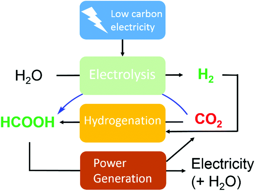 | ||
| Fig. 1 Storage and utilization of low carbon energy using formic acid. | ||
2. Hydrogenation of carbon dioxide

| (1) |

| (2) |
2.1. Homogeneous catalysis
![[thin space (1/6-em)]](https://www.rsc.org/images/entities/char_2009.gif) :1).34 A water soluble Rh complex, a Wilkinson-type catalyst [RhCl(mtppms)3] (mtppms = monosulfonated triphenylphosphine) (3), was later reported for the hydrogenation in H2O/dimethylamine with a TON of 3439.35 The ligand effect was further investigated by keeping the solvent system intact. Combination of several mono- and bidentate phosphines/[Rh(cod)(μ-Cl)2] (4) resulted in the formation of FA with concentrations up to 2.58 M. It was concluded that chelating ligands were more active.36 Importantly, while most hydrogenation reactions were studied in organic solvents, it was found that the presence of water may increase the catalytic aptitude. The Lau group demonstrated a significant rate enhancement using [TpRuH(PPh3)(CH3CN)] [Tp = hydrotris(pyrazolyl)borate] (5) in the presence of water (Fig. 2).37 The hydrogen bonding of a coordinated water molecule was found to facilitate the CO2 insertion into the Ru–H bond.
:1).34 A water soluble Rh complex, a Wilkinson-type catalyst [RhCl(mtppms)3] (mtppms = monosulfonated triphenylphosphine) (3), was later reported for the hydrogenation in H2O/dimethylamine with a TON of 3439.35 The ligand effect was further investigated by keeping the solvent system intact. Combination of several mono- and bidentate phosphines/[Rh(cod)(μ-Cl)2] (4) resulted in the formation of FA with concentrations up to 2.58 M. It was concluded that chelating ligands were more active.36 Importantly, while most hydrogenation reactions were studied in organic solvents, it was found that the presence of water may increase the catalytic aptitude. The Lau group demonstrated a significant rate enhancement using [TpRuH(PPh3)(CH3CN)] [Tp = hydrotris(pyrazolyl)borate] (5) in the presence of water (Fig. 2).37 The hydrogen bonding of a coordinated water molecule was found to facilitate the CO2 insertion into the Ru–H bond.
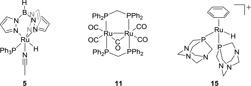 | ||
| Fig. 2 Structures of selected ruthenium-based catalysts 5, 11 and 15. | ||
Employment of super critical CO2 (scCO2) for hydrogenation was first introduced by the Noyori group. In the presence of NEt3 and a trace amount of water, RuCl2(PMe3)4 (6) and Ru(H)2(PMe3)4 (7) gave high initial rates (TOF of 1400 h−1), which were attributed to the enhanced miscibility of H2 in scCO2.38 Using DMSO or MeOH instead of water led to an improved catalytic efficacy (TOF of 4000 h−1), presumably due to the stabilization of catalytic intermediates by hydrogen bonding.39 Fachinetti and co-workers also used the same catalytic system in neat NEt3 using a biphasic medium.40 The Jessop group reported a high TOF of 95000 h−1 at 50 °C using [RuCl(OAc)(PMe3)4] (8) and NEt3 in pentafluorophenol under 190 bar H2/CO2.41In situ generated catalysts from [RuCl2(C6H6)]2 (9) and various phosphine ligands, such as PMe3, PPhMe2, bis(diphenylphosphino)-methane (dppm), 1,1-bis-(diphenylphosphino)ethane (dppe), and cis- or trans-Ph2PCH![[double bond, length as m-dash]](https://www.rsc.org/images/entities/char_e001.gif) CHPPh2, were examined in a MeOH/triisopropylamine (NiPr3) solvent, and it was concluded that steric factors play the decisive role in comparison to electronic ones for monodentate phosphines.42 For weakly basic diphosphines, smaller bite angles offered better activity, while, for more basic diphosphines, a reverse trend was observed.
CHPPh2, were examined in a MeOH/triisopropylamine (NiPr3) solvent, and it was concluded that steric factors play the decisive role in comparison to electronic ones for monodentate phosphines.42 For weakly basic diphosphines, smaller bite angles offered better activity, while, for more basic diphosphines, a reverse trend was observed.
In 1995, Chen and co-workers demonstrated that employment of cis-[Ru(Cl2bpy)2(H2O)2][CF3SO3]2 (bpy = 2,2′-bipyridine) (10) in EtOH in the presence of NEt3 resulted in TONs of up to 5000.43 Puddephatt et al. reported a dinuclear ruthenium phosphine complex [Ru2(μ-CO)-(CO)4(μ-dppm)2] (11) for CO2 hydrogenation in the presence of NEt3 with a TON of 2160 (Fig. 2). 1.4 M FA was obtained under 38 bar H2/CO2 (1:1) and the FA concentration was doubled by doubling the total gas pressure.44 The Joó group examined a number of rhodium and ruthenium based catalysts viz. [RhCl(tppms)3] (12), [RuCl2(mtppms)2]2 (13), and [RuCl2(pta)4] (14) (tppms = meta-trisulfonated triphenylphosphine, PTA = 1,3,5-triaza-7-phosphaadamantane) in aqueous medium without amine additives.45–49 A maximum TOF of 9600 h−1 was achieved using complex 13 at 80 °C in a 0.3 M sodium bicarbonate solution. Catalyst 12 was found to hydrogenate the aqueous solution of CaCO3 (0.1 M) to FA/formate under 100 bar H2/CO2 (4:1). These findings inspired several groups to use aqueous medium for homogeneous CO2 and bicarbonate hydrogenation. Subsequently, Kathó and co-workers reported the hydrogenation of 0.1 M HCO3− solution under 10 MPa H2 using [(C6H6)RuH(pta)2]+ (15) and proposed a mechanism involving hydride transfer to the bicarbonate moiety (Fig. 2).50 The Beller group reported that the incorporation of various phosphine ligands into precatalyst 9 resulted in improved reactivity. When dppm was used as a ligand, a high TOF of 1260 h−1 was obtained. However, the catalytic activity was lost after the first few hours.51
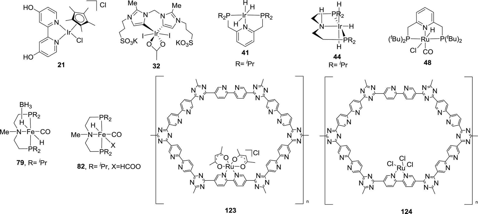
In 2004, Himeda and co-workers employed hydroxy functionalized proton-responsive bipyridine (bpy)/phenanthroline (phen)-type ligands to develop a number of new catalysts.52–55 Such proton responsive units allow the electronic properties to be controlled upon changing the pH values of the reaction medium. Under alkaline conditions, deprotonation of the hydroxyl group afforded the corresponding oxyanions as efficient hydrogenation catalysts. Initially, Ru(II), Rh(III) and Ir(III) complexes containing a 4,7-dihydroxy-1,10-phenanthroline (dhphen) ligand skeleton (16–18) were tested towards hydrogenation of bicarbonate solutions (Fig. 3). [Cp*Ir(dhphen)Cl]Cl (17) (Cp* = 1,2,3,4,5-pentamethylcyclopentadienyl) showed the best performance with a TON of 21000 (formate concentration of 0.42 M) and a TOF of 23000 h−1 under basic conditions at 120 °C. Interestingly, an improved TOF of 33000 h−1 was achieved with decreasing the catalyst concentration under otherwise similar conditions. The Ru analog 16 displayed an almost 3-fold-increase in the final formate concentration (1.2 M), albeit with a decreased TOF of 3360 h−1 at 120 °C. In the presence of an unsubstituted 1,10-phenanthroline ligand, both Ir and Rh complexes 19 and 20 did not show any reactivity (Fig. 3). These findings indicated the importance of oxyanionic species formation, presumably to enhance the solubility. The strong electron-donating of the oxyanion, generated from [Cp*Ir(4dhbp)Cl]Cl (21) (4dhbp = 4,4′-dihydroxy-2,2′-bipyridine), imparted higher catalytic efficiency and was found 1000 times more reactive with a TOF of 5100 h−1 than the unsubstituted [Cp*Ir(bpy)Cl]Cl (22) with a TOF of 4.7 h−1 at 80 °C under 1 MPa H2/CO2 (1:1) (Fig. 3). Himeda, Fujita and co-workers further designed a binuclear Ir complex (23) having a bipyrimidine ligand with four hydroxyl groups for bicarbonate (2 M KHCO3) hydrogenation (Fig. 3).56 Under 50 bar H2, formate salt was formed with a TOF of 53800 h−1 and a TON of 79000 at 80 °C. Similar activity was observed using the corresponding monomer analog (24), suggesting that bimetallic cooperativity may not be the crucial factor (Fig. 3). Interestingly, Ir complex 25 bearing a non-functionalized imidazoline moiety also showed similarly good activity (Fig. 3).57 The importance of the pendant base effect was proposed to enhance proton transfer through a water bridge in stabilizing the transition state involving the rate-determining H2 heterolysis step.
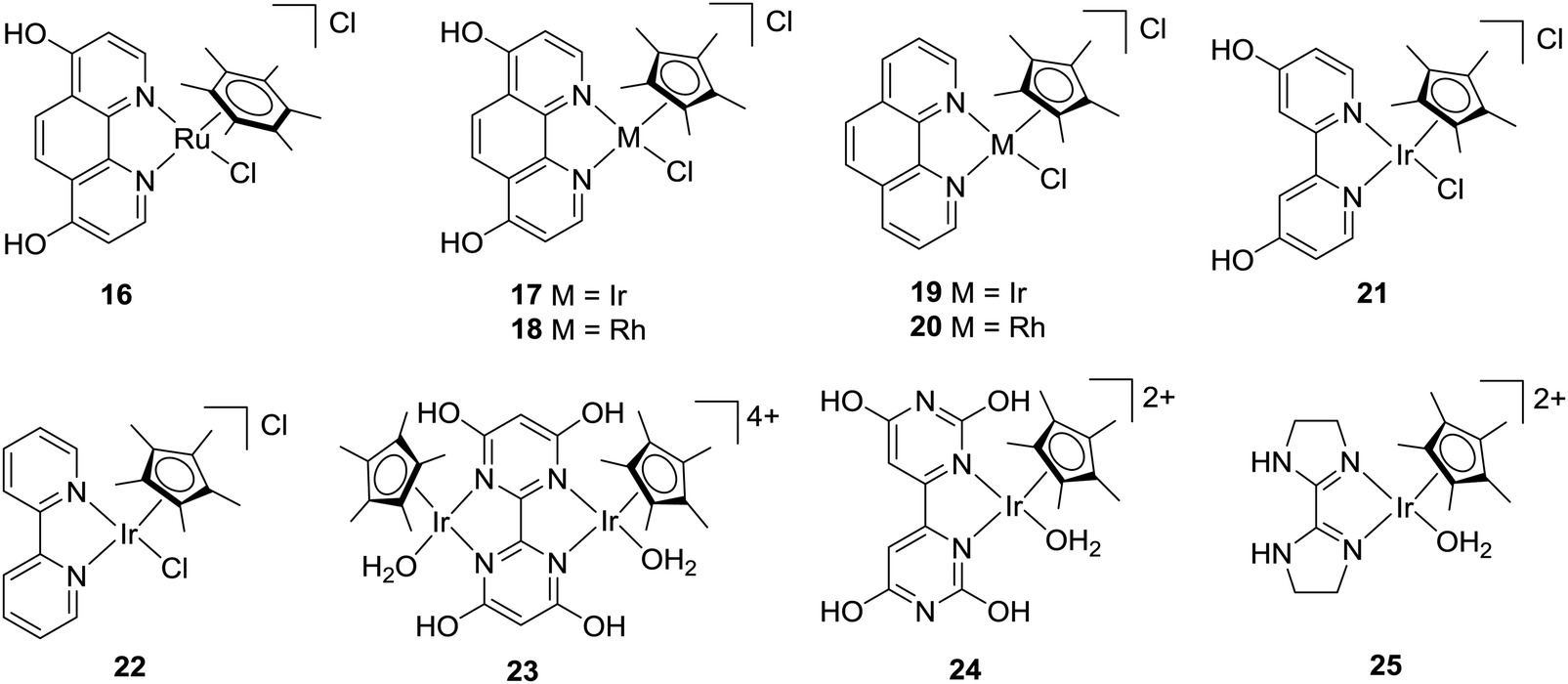 | ||
| Fig. 3 Catalysts for CO2 hydrogenation in basic aqueous media. | ||
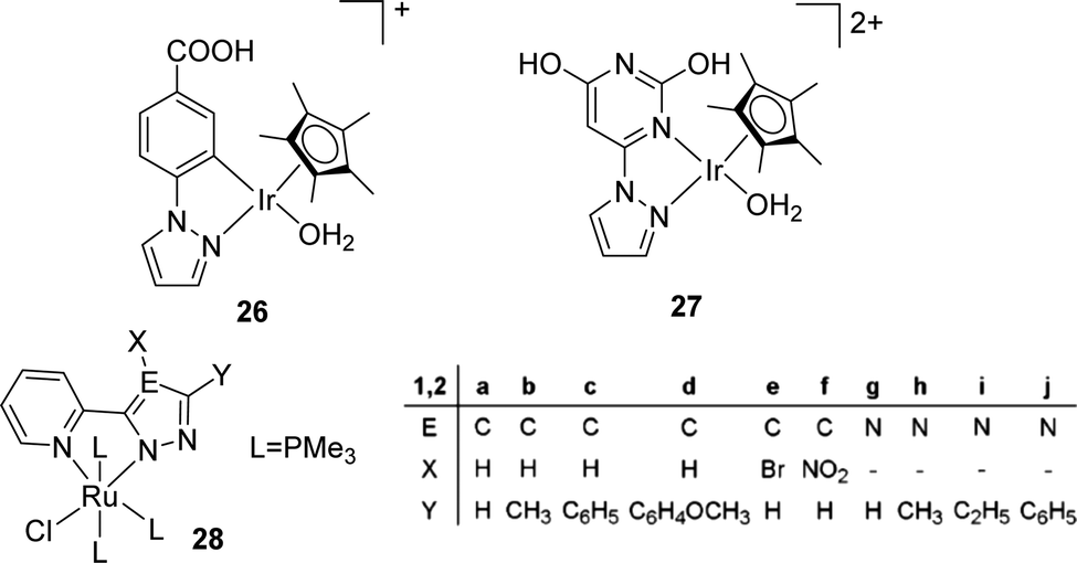
The Fukuzumi group reported a proton-responsive catalyst [Cp*Ir(N1)(OH2)]+ (26) for the efficient production of formate in 2.0 M KHCO3 aqueous solution (pH 8.8) with a TON of 100 (20 h) and a TOF of 6.8 h−1 at ambient temperature and pressure (Fig. 4).58 Himeda et al. also reported an Ir complex (27) bearing pyrimidine and imidazole groups with enhanced reactivity (TOFs ranging from 440 h−1 at 50 °C to 6440 h−1 at 120 °C) under 10 bar H2/CO2 (1:1) in basic media (Fig. 4).59 Thiel and co-workers studied a series of Ru(II) complexes [(N-N′)RuCl(PMe3)3] (28a–j) (N-N′ = pyridinylazolato) with variable electronic properties to probe the structure–activity relationships for CO2 hydrogenation and a maximum TON of 4800 was achieved (Fig. 4).60 Ru catalysts having simple phosphite ligands, such as P(OMe)3, P(OEt)3, P(OiPr)3, and P(OPh)3, showed good reactivities under the scCO2 condition with DBU (1,8-diazabicyclo[5.4.0]undec-7-ene) and the highest TON of 6630 was obtained with P(OMe)3.60
 | ||
| Fig. 4 Structures of selected Ir and Ru catalysts. | ||
Several Ir and Ru complexes containing N-heterocyclic carbene (NHC) ligands were studied by the Peris group using H2 or iPrOH (isopropanol) as the hydrogen source for CO2 reduction to FA (Fig. 5).61 The strong σ donating ability of NHC ligands was crucial for the thermal stability of these catalysts. Ir 29 gave a TON of 150 under 50 bar CO2 in the presence of 0.5 M KOH at 110 °C in iPrOH (Fig. 5). Employing bis NHC based Ir complex 30, a TON of 1600 was achieved under 60 bar H2/CO2 (1:1) in a 2 M KOH solution at 80 °C (Fig. 5). On the other hand, analogous Ru 31 resulted in a significant improvement in the TON (23000) even under a lower pressure (40 bar H2/CO2) but at an elevated temperature of 200 °C (Fig. 5). When the ligand was modified by incorporating sulfonate substituents into the carbon side chains, the corresponding more water-soluble complex 32 afforded a TON of 190000 under 60 bar H2/CO2 (1:1) in a 1 M KOH solution at 200 °C (Fig. 5). However, under the transfer hydrogenation condition, the catalyst lifetime decreased significantly (TON = 2700).62
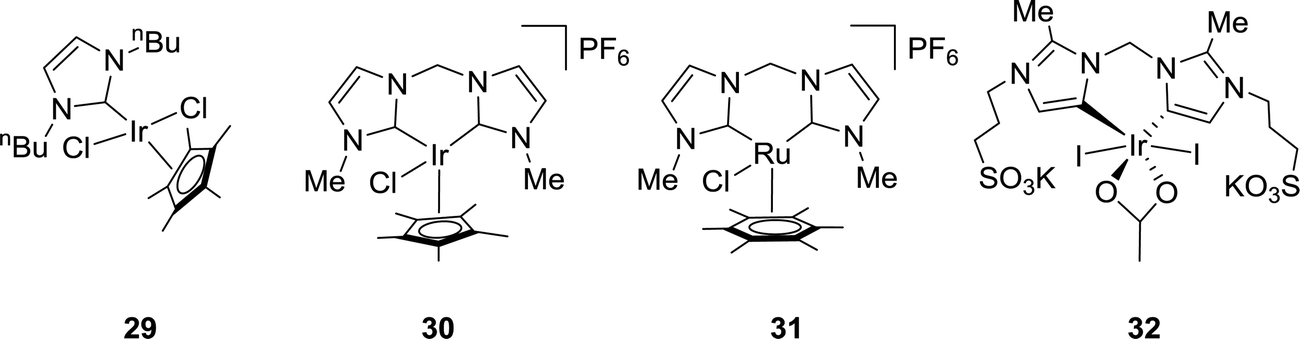 | ||
| Fig. 5 Carbene-based catalysts 29–32. | ||
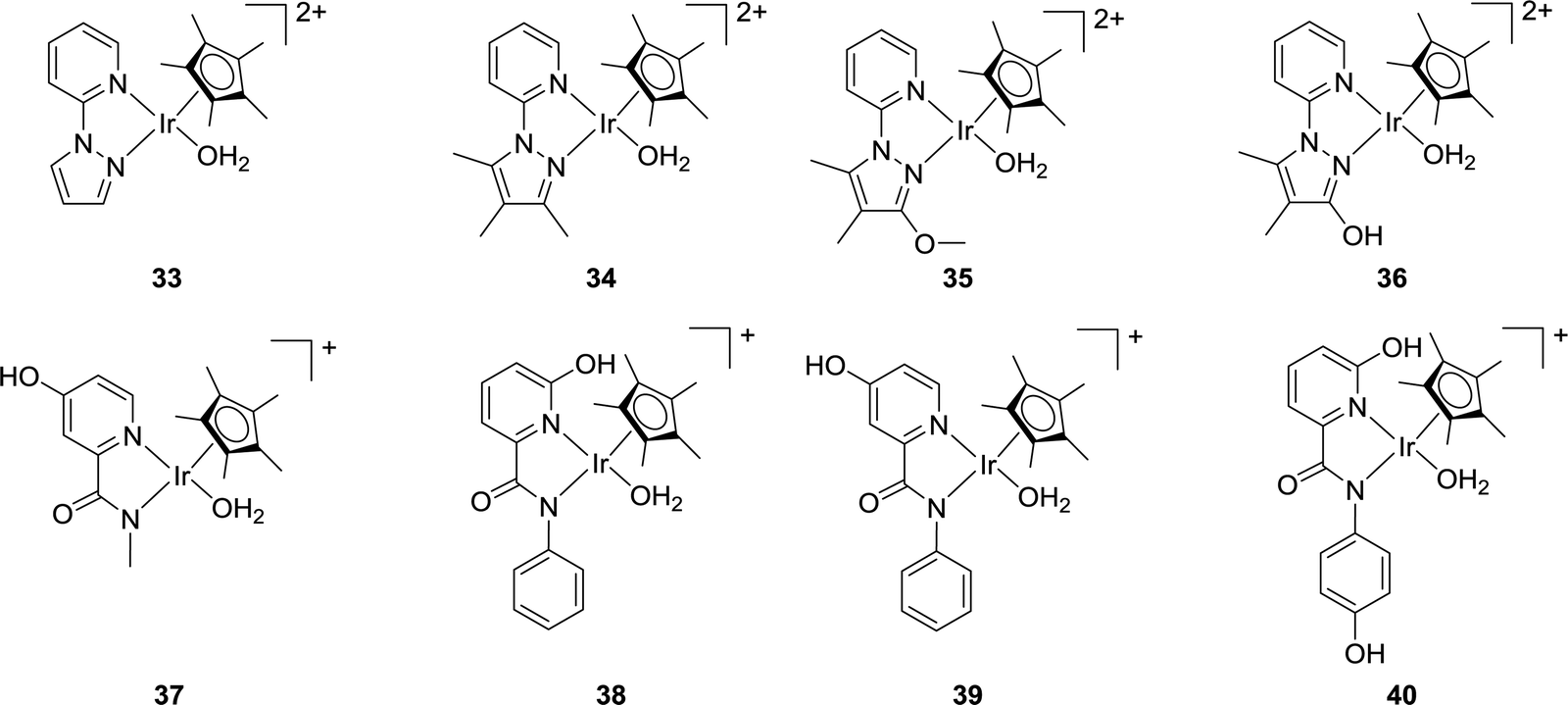
Himeda and co-workers have reported a variety of Cp*Ir complexes (33–36) bearing pyridine-pyrazole moieties for CO2 hydrogenation to formate (Fig. 6).63 The introduction of an OH group on the pyrazole ring led to improved catalytic efficiency. Using 36 under 1.0 MPa H2/CO2 (1:1) in 1.0 M aqueous NaHCO3 solution at 50 °C, a maximum TON of 7850 was obtained after 48 h. Under alkaline conditions, the OH group was converted to an oxyanionic species via deprotonation which was more electron donating than the neutral OH group to offer improved reactivities. Very recently, they also prepared several Cp*Ir catalysts (e.g.37–40) based on picolinamidate ligands with a concept of enhanced electron-donating ability of the ligand via the coordinated anionic nitrogen atom (Fig. 6).64 The influence of the proton responsive OH group at the ortho- or para-position of the pyridine ring was investigated. Catalyst 38 having an anionic coordinating amide N atom and an OH group in the second coordination sphere showed the best reactivity towards CO2 hydrogenation in basic aqueous solution under ambient conditions with a TOF of 198 h−1. Interestingly, complex 37, devoid of any ortho-OH groups, exhibited better long-term efficiency with a TON of 14700 after 348 h under ambient conditions.
 | ||
| Fig. 6 Pyrazole and picolinamidate derived catalysts 33–40. | ||
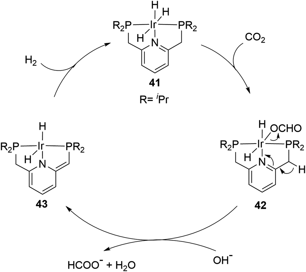
A record high TON was achieved by the Nozaki group in 2009 using a PNP ([2,6-bis(di-isopropylphosphinomethyl)pyridine]) based Ir trihydride catalyst (41) in a 1 M aqueous KOH solution (Fig. 7).65 A TOF of 150000 h−1 at 200 °C under 50 bar H2/CO2 (1:1) and an unprecedented TON of 3500000 at 120 °C in a total period of 48 hours were obtained. High temperature, pressure, a strong base and a polar solvent were all necessary for these high reactivities to be realized. A plausible mechanism was proposed based on a combined computational and experimental study. The insertion of CO2 into an Ir–H bond from 41 to 42 first occurs, followed by the deprotonation of a CH2 arm and the dearomatization of the central pyridine ring to give 43 with dissociation of formate as a rate determining step. The hydrogenation of 43 then regenerates 41 to complete the catalytic cycle (Fig. 7).66
 | ||
| Fig. 7 The proposed mechanism for CO2 hydrogenation by 41. | ||
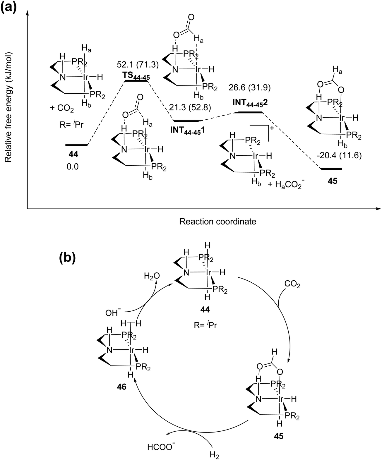
Hazari and co-workers prepared an air-stable and water soluble saturated analog, IrH3(PNP) (44),67 and showed that the presence of a strong electron-donating trans hydride ligand may weaken the Ir–H bond to facilitate the CO2 insertion process to give a hydrogen bonded [Ir]-formate species (45; Fig. 8). An overall TON of 348000 was achieved after 24 h at 185 °C under 56 bar H2/CO2 (1:1). DFT calculations were conducted to elucidate the mechanism. The influence of the H-bond donor was supported by comparing CO2 insertion into the syn (Ha) and anti (Hb) hydrides with respect to the N–H bond (Fig. 8a). The H-bond assisted CO2 insertion into Ha was found to be more favored over that into Hb, which was thermodynamically uphill. Overall, the CO2 insertion into Ha or Hb resulted in an H-bound formate intermediate. The dissociation of the formate moiety and re-coordination then led to an O-bound species 45. The formate in 45 can be replaced by H2 to give the dihydrogen intermediate 46. Deprotonation of the coordinated dihydrogen then regenerates the trihydride 44 (Fig. 8b). Experimental evidence and theoretical results suggested that nucleophilic attack of hydride on CO2 is the rate-limiting step.
 | ||
| Fig. 8 (a) Pathway for insertion of CO2 into 44. Numbers in parentheses are for insertion into Hb. (b) The proposed mechanism for CO2 hydrogenation by 44. | ||
Pincer type Ru catalysts have also been employed for CO2 hydrogenation. For example, the Sanford group demonstrated that the dearomatized Ru–PNN pincer complex (47) afforded a TON of 23000 in the presence of K2CO3 under 40 bar H2/CO2 (3:1) at 120 °C in diglyme (Fig. 9).68 When the amine donor group was replaced by a phosphine, the Pidko group showed that the pincer complex (48) gave a TOF of 1100000 h−1 and a TON of 37000 under 40 bar H2/CO2 (3:1) at 120 °C using DMF (dimethylformamide) as the solvent and DBU as the base (Fig. 9).69 Even lowering the overall pressure to 5 bars and the reaction temperature to 90 °C, a high TOF of 60000 h−1 was achieved. Experimental evidence and DFT calculations suggested that a dihydrido Ru species (49) is the active catalyst (Fig. 9).70,71 Szymczak and co-workers have also evaluated a series of Ru complexes (e.g.50–52) having an N,N,N-pincer ligand backbone and studied the effects of the steric bulk, ligand charges and bite angles on the catalytic activity (Fig. 9).72 It was concluded that decreased ligand charge and the presence of o-substituents expedite the catalytic efficacy, whereas the bite angles have only small impacts. Under the optimized conditions, 51 was found to be the best with a TON of 60000 after 18 h at 120 °C.
 | ||
| Fig. 9 Pincer type Ru catalysts 47–52. | ||
The Huang group has shown that replacing the CH2 spacers in pyridine-based pincer complexes led to distinct kinetic and thermodynamic properties.73,74 A new variety of PN3P–Ru(II) pincer complex (53) was prepared for CO2 hydrogenation in a 1:1 THF (tetrahydrofuran)/H2O biphasic system (Fig. 10). Hydrogenation of NaHCO3 solution was also realized with a TON of 33000 after 50 h under 1600 psi H2 at 130 °C.75 A combination of direct CO2 capture from air by various amines followed by hydrogenation was demonstrated with an efficiency of 39%. A biphasic 2-MeTHF/H2O system using PMDTA (N,N,N′,N′′,N′′-pentamethyldiethylenetriamine) as the CO2 absorber was established for easy product separation and catalyst recycling. Interestingly, in contrast to Nozaki's results, PN3P–Ir pincer complexes (54 and 55) only gave a maximum TON of 5100 under 120 psi H2/CO2 (1:1) in 1:4 THF/H2O at 130 °C for direct CO2 hydrogenation to formate (Fig. 10).76 A possible catalyst deactivation pathway was suggested by the formation of a dearomatized PN3P*Ir(I)–CO species (56; Fig. 10).
 | ||
| Fig. 10 Phosphorus-nitrogen PN3P–pincer complexes 53–56. | ||
Schaub and Paciello developed for the first time a scalable methodology based on an integrated CO2 hydrogenation, catalyst recycling, and FA isolation process.77 Reactions were performed in a biphasic diol/trihexylamine (NHex3) medium using a homogeneous ruthenium catalyst, Ru(H)2(PnBu3)4 (57), leading to the formation of a NHex3·FA salt. Upon completion, the product-rich phase was extracted with NHex3, followed by separation by distillation, whereas the amine phase containing the catalyst was recycled for the next hydrogenation process. Pioneering work from He et al. led to the development of efficient CO2 capture and subsequent hydrogenation.78 PEI600 (polyethylenimine, Mw = 600) is stable and non-volatile, and it can absorb CO2 with a capacity of 0.159 g of CO2/0.3 g of amine in ethylene glycol. Heldebrant et al. reported the RuCl2(PPh3)3 (58) catalyzed hydrogenation of captured CO2 into methyl formate with a TON of up to 5100 after 40 h in a switchable ionic liquid (IL) comprising DBU and methanol at 140 °C.79 Higher reaction temperatures and an excess of methanol promoted the esterification process and in turn led to methyl formate formation. Leitner and co-workers employed a suitable catalyst/IL matrices for the production of pure FA.80 The catalyst precursors, [Ru(cod)X2] (59) (X2 = acac (acetylacetonate), Cl2, or (methylallyl)2), were combined with tppms (monosulfonated triphenylphosphine)/PBu4 (tetrabutylphosphonium) or EMIM (1-ethyl-3-methylimidazolium) in continuous-flow hydrogenation of scCO2. They further developed biphasic systems for integrated CO2 hydrogenation and facile product separation. HNMe2, HNiPr2, and NEt3 were used as amine sources and the FA adduct was extracted into the aqueous phase, whereas the catalyst was immobilized in a hydrophobic solvent.
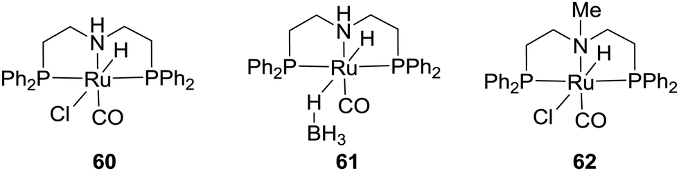
The commercial Takasago PNHP-pincer Ru catalysts (60 and 61) and their methylated analog (62) were examined by the Prakash and Olah group for H2 storage in organic solvent/H2O in the presence of alkali hydroxides, carbonates, bicarbonates, and CO2 (Fig. 11).8160 and 61 could achieve formate formation with TOFs of 1688 and 958 h−1, respectively, using NaHCO3 in THF/H2O at 80 °C under 40 bar H2. Interestingly, the presence of the N–H group in the ligand backbone may not be necessary as 62 also showed a similar catalytic performance with a TOF of 1096 h−1 in a dioxane/H2O solution of NaOH at 70 °C under 80 bar H2/CO2 (3:1). When integrated with CO2 capture in the presence of amines, high activities were reached using tetramethylguanidine (TMG) and DABCO (1,4-diazabicyclo[2.2.2]octane) with up to 95% yield and a TON of 7375 in a dioxane/water medium under 50 bar H2.82 Similar results were also demonstrated by Prakash and co-workers using hydroxide bases (NaOH, KOH, and CsOH) for integrated CO2 capture and subsequent conversion to formate salts.83,84 Employment of a biphasic 2-MeTHF/water system allowed easy separation and reuse of the catalyst(s) over multiple cycles without a significant decrease in catalytic aptitude. Finally, Table 2 lists some of the noble-metal-based catalytic systems for CO2 hydrogenation.
 | ||
| Fig. 11 Examples of commercial Takasago catalysts. | ||
| Catalyst precursor | Solvent | Base | H2/CO2 (bar) | Temp. (°C) | TON | TOF (h−1) | Ref. |
|---|---|---|---|---|---|---|---|
| [RuH2(PPh3)4] (1) | C6H6/H2O | NEt3 | 25/25 | RT | 87 | 4 | 33 |
| [Rh(cod)Cl]2/dppb (2) | DMSO | NEt3 | 20/20 | RT | 1150 | 30–47 | 34 |
| [RhCl(mtppms)3] (3) | H2O | NHMe2 | 20/20 | RT | 3439 | 290 | 35 |
| [TpRuH-(PPh3)(CH3CN)] (5) | CF3CH2OH | NEt3 | 25/25 | 100 | 1815 | 110 | 37 |
| RuCl2(PMe3)4 (6) | scCO2 | NEt3/H2O | 85/120 | 50 | 7200 | 1040 | 38 |
| RuH2(PMe3)4 (7) | scCO2 | NEt3/H2O | 85/120 | 50 | 3700 | 1400 | 38 |
| RuH2(PMe3)4 (7) | scCO2 | NEt3/DMSO | 85/120 | 50 | 2000 | 4000 | 39 |
| [RuCl(OAc)(PMe3)4] (8) | scCO2 | NEt3/C6F5OH | 70/120 | 50 | 31200 |
95000 |
41 and 42 |
| [Ru(Cl)2(bpy)2(H2O)2][CF3SO3]2 (10) | EtOH | NEt3 | 30/30 | 150 | 5000 | 625 | 43 |
| [Ru2(μ-CO)-(CO)4(μ-dppm)2] (11) | Acetone | NEt3 | 35/35 | RT | 2160 | 103 | 44 |
| [RuCl2(mtppms)2]2 (13) | H2O | NaHCO3 | 60/35 | 80 | NA | 9600 | 49 |
| [(C6H6)RuH(pta)2]+ (15) | H2O | NaHCO3 | 100/0 | 80 | NA | 409 | 50 |
| [RuCl2(C6H6)]2 (9)/dppm | H2O | NaHCO3 | 50/35 | 70 | 2520 | 1260 | 51 |
| [Cp*Ir(dhphen)Cl]Cl (17) | H2O | KOH | 30/30 | 120 | 21000 |
23000 |
52 |
| [Cp*Ir(4dhbp)Cl]Cl (21) | H2O | KOH | 5/5 | 80 | 11000 |
5100 | 55 |
| [Cp*Ir(4dhbp)Cl]Cl (21) | H 2 O | KOH | 30/30 | 120 |
190![[thin space (1/6-em)]](https://www.rsc.org/images/entities/b_char_2009.gif) 000 000
|
42000
|
54 |
| [(Cp*Ir)2(thbpm)(H2O)2](SO4)2 (23) | H2O | KHCO3 | 50/0 | 80 | 79000 |
53800 |
56 |
| [Cp*Ir(N1) (OH2)]+ (27) | H2O | KHCO3 | 10/0 | 120 | NA | 6440 | 59 |
| IrH 3 (PNP) (41) | H 2 O/THF | KOH | 4/4 | 200 |
300000
|
150000
|
65 and 66 |
| IrH 3 (PNP) (41) | H 2 O/THF | KOH | 4/4 | 120 |
3500000
|
73000
|
65 and 66 |
| IrH3(PNP) (44) | H 2 O | KOH | 28/28 | 185 |
348000
|
14500
|
67 |
| Ru(PNN)CO(H) (47) | Diglyme | K2CO3 | 30/10 | 200 | 23000 |
2200 | 68 |
| [Ru(H)(PNP)Cl(CO)] (48) | DMF | DBU | 30/10 | 120 |
200000
|
1100000
|
69 |
| [Ru(H)(PNP)Cl(CO)] (48) | DMF | DBU | 2.5/2.5 | 90 | NA | 60000 |
69 |
| [Ru(NNNN)(Cl)2(PPh3)] (51) | DMF | DBU | 70/6 | 120 | 60000 |
NA | 72 |
| Ru(PN3P) (53) | H2O/THF | NaHCO3 | 110/0 | 130 | 33000 |
13000 |
75 |
| IrH3(PN3P) (55) | H2O/THF | KOH | 4/4 | 130 | 5100 | 283 | 76 |
| [Cp*Ir(N–N)(OH2)]2+ (36) | H2O | NaHCO3 | 5/5 | 50 | 7850 | 650 | 63 |
| [Cp*Ir(N–N)(OH2)]+ (37) | H2O | NaHCO3 | 1/1 | RT | 14700 |
NA | 64 |
| [IrI2(AcO)(bis-NHC)] (32) | H 2 O | KOH | 30/30 | 200 |
190000
|
2500 | 62 |
| [Ru(H)(PNP)Cl(CO)] (60) | THF/H2O | NaHCO3 | 40/0 | 80 | NA | 1688 | 82 |
| [Ru(H)(PNMeP)Cl(CO)] (62) | Dioxane/H2O | NaOH | 60/20 | 70 | NA | 1096 | 82 |
:4) in a DMSO/DBU solution.85 In 2010, the Beller group developed an iron based catalytic system for hydrogenation of a bicarbonate solution.86 A system comprising Fe(BF4)2·6H2O/tris[2-(diphenylphosphino)-ethyl]phosphine (65) gave the formate product with a TON of 610 under 60 bar H2 in MeOH at 80 °C. Under similar reaction conditions, the analogous Co(BF4)2·6H2O/tris[2-(diphenylphosphino)ethyl]phosphine (66) catalyst achieved a comparable activity with a TON of 645. Interestingly, improved activities, a TON of 3877 and a TOF of 190 h−1, were realized at an elevated temperature of 120 °C.87 Modifying the ligand system to tris[(2-diphenylphosphino) phenyl]phosphine with Fe(BF4)2·6H2O (67) afforded enhanced activity with a TON of 7500 at 100 °C.87 Application of the same catalyst for CO2 hydrogenation using 30 bar H2/CO2 (1:1) in a MeOH/NEt3 solution yielded FA and methyl formate with a total TON of 1700. Improved formate selectivity was observed in the presence of water where formation of methyl formate was suppressed. Linehan et al. reported a Co(dmpe)2H (dmpe: 1,2-bis(dimethylphosphino)-ethane) complex (68) for CO2 hydrogenation in THF in the presence of a very strong base, Verkade's base (Fig. 12).88 Under 1.8 and 20 atm of equimolar H2/CO2 pressure, high TOFs of 6400 and 74000 h−1 were obtained, respectively, at room temperature. Initially, the metal hydride gets transferred to CO2 to form [Co(dmpe)2]+ (69) and formate. Subsequently, addition of H2 resulted in Co(III) dihydride intermediate 70, which further underwent base mediated deprotonation to regenerate the Co(I) hydride (Fig. 12a). To further support the proposed mechanism of the hydride transfer step, detailed DFT calculations were carried out.89 Two possible routes were considered: (I) direct hydride transfer from the metal complex to an encountered CO2 (Fig. 12b) and (II) an associative pathway involving the binding of CO2 through its carbon to the metal (Fig. 12c). For the direct hydride transfer process (Fig. 12b), electrostatic interactions between the Co–H moiety and CO2 resulted in Int681I. The free energy of activation for the hydride transfer TS681I was calculated to be 17.2 kcal mol−1. Subsequently, nucleophilic attack of the hydride to CO2 resulted in an H-bound formate Int682I species, which underwent an intramolecular rearrangement to generate an O-bound formate complex via transition state TS682I. In the associative mechanism (Fig. 12c), the initial step is the endergonic formation of species Int681II. This association proceeds with the binding of CO2 to the Co, affording a six coordinated intermediate Int682IIviaTS681II with an energy barrier of 15.8 kcal mol−1. In the following step, intramolecular hydride transfer occurs from the Co center to the electrophilic carbon of CO2 to generate H-bound intermediate Int683II through TS682II. Int683II has a similar relative energy and structure to those of Int682I and can follow the same pathway to yield an O-bound formate complex. Overall, the associative pathway is favored by 1.4 kcal mol−1 over the direct hydride transfer and was proposed to be the preferred mechanism. It is evident that the rate determining step was the binding of CO2 to Co and this was consistent with the fact that the rate increased linearly with the CO2 gas pressure while it was independent of both the hydrogen pressure and base concentration. Despite the decent activity, the main drawback was the necessity of Verkade's base to regenerate 68 from intermediate [Co(dmpe)2(H)2]+ (70). The ratio of CO2/H2 was found to be crucial, as with increasing the ratio above 1, CO formation occurred due to the reverse water–gas shift (RWGS) reaction.88
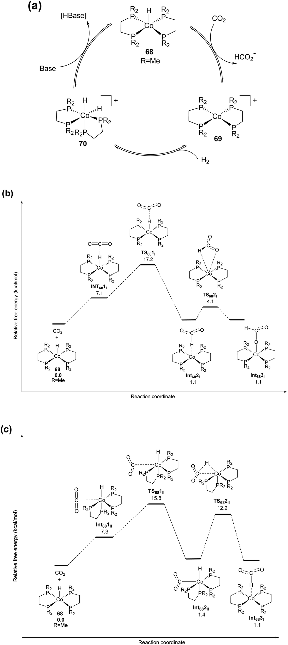 | ||
| Fig. 12 (a) Proposed reaction mechanism for CO2 hydrogenation using 68. Free energy profiles of the (b) direct hydride transfer pathway and (c) associative pathway using 68. | ||
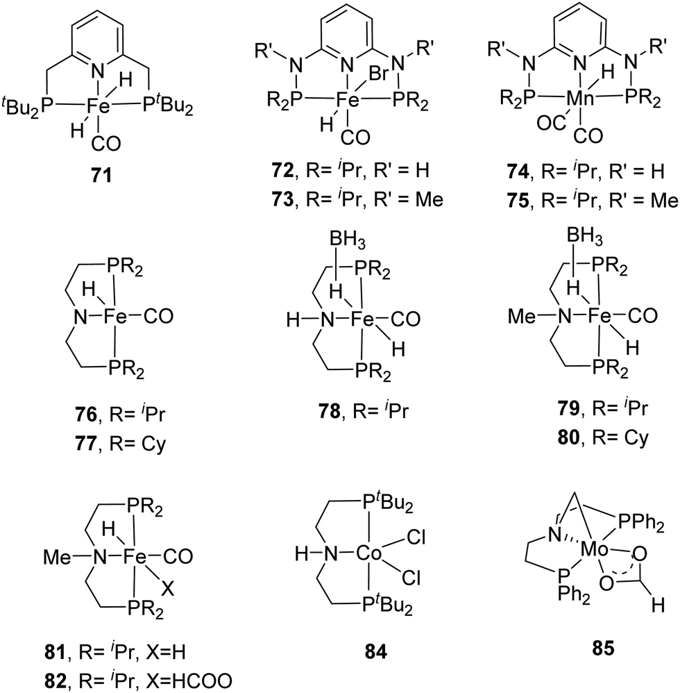
Milstein et al. employed a pyridine-based PNP–Fe pincer complex (71) for CO2 and bicarbonate hydrogenation under low hydrogen pressures (Fig. 13).90 Under 10 bar H2/CO2 (2:1), a maximum TON of 788 and a TOF of up to 160 h−1 were obtained. Subsequently, the Kirchner and Gonsalvi group demonstrated the activity of a set of iron PN3P-pincer complexes having either N–H (72) or N–Me (73) arms towards CO2 and bicarbonate hydrogenation under comparable reaction conditions (Fig. 13).91 Employing 72 under 8.5 bar H2 at 80 °C in a H2O/THF (4:1) solvent, a TON of 140 was achieved for bicarbonate hydrogenation after 16 h. Using a higher H2 pressure of 90 for 24 h yielded an improved TON of 4560. For CO2 hydrogenation, a maximum TON of 10275 was obtained using 73 in the presence of DBU in EtOH. The importance of the protic solvent (H2O) was realized as the reaction did not proceed in THF, presumably because the protic solvent helps to stabilize the catalytic intermediates via hydrogen bonding. The Mn(I) analogs 74 and 75 were also investigated by the same group (Fig. 13).9274 displayed better activity compared to the Fe counterpart with a TON of 5520 under 80 bar H2/CO2 (1:1) in the presence of DBU in THF/H2O at 80 °C. Employing LiOTf (lithium triflate) as an additive and lowering the catalyst loading to 0.002 mol% resulted in a larger TON of 30000.
 | ||
| Fig. 13 Selected non-noble metal catalysts having a pincer backbone for CO2 hydrogenation. | ||
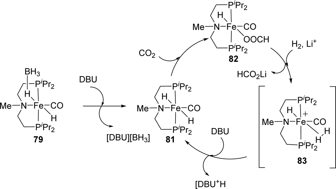
Hazari, Bernskoetter and co-workers studied a number of Fe(II) carbonyl hydride complexes bearing a saturated pincer ligand (76–82, Fig. 13).93 Addition of a Lewis acid such as LiOTf was found to increase the reaction rates. The best results were obtained with TONs of 58990 and 46130 for 79 and 82, respectively, after 24 h. Mechanistic insights suggested initial base promoted activation of 79 followed by rapid CO2 insertion into the Fe–H bond leading to a metal coordinated formate species as a catalytic resting state (82) (Fig. 14). Lewis acid assisted substitution of the formate ligand by dihydrogen occurred to yield a transient cationic Fe(II)–H2 complex (83; Fig. 14). Subsequent deprotonation of the dihydrogen fragment by DBU completes the catalytic cycle. In 2016, Bernskoetter et al. synthesized analogous Co and Mo catalysts (84 and 85) for CO2 hydrogenation with LiOTf as the Lewis acid additive (Fig. 13). The highest TON of 29000 was obtained for 84 in CH3CN at 45 °C under 69 bar H2/CO2 (1:1) using DBU as the base after 16 h,94 but poor reactivity (TON of 35) was observed for 85.95
 | ||
| Fig. 14 Proposed reaction mechanism for CO2 hydrogenation using 79. | ||
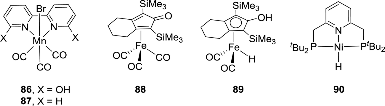
While Cp*Ir(III) complexes tethered to proton-responsive dihydroxybipyridine ligands were active catalysts for CO2 hydrogenation,52–55 Fujita et al. have shown that their Co(III) counterparts only offered limited catalytic aptitudes due to poor thermal stability.96 However, the Khusnutdinova group demonstrated that with Mn complex 86 bearing 6,6′-dihydroxy-2,2′-bipyridine (Fig. 15), a TON of 6250 (98% yield) was obtained when the reaction was performed under 6 MPa H2/CO2 (1:1) in the presence of DBU in CH3CN at 65 °C.97 Employing Mn 87 yielded only a trace amount of formate under otherwise identical reaction conditions, indicating the crucial role of the adjacent –OH group (Fig. 15).
 | ||
| Fig. 15 Other selected non-noble metal catalysts. | ||
In 2015, Yang, Zhou and co-workers examined Fe complex 88 for hydrogenation of bicarbonates and CO2 to formates and identified the Knölker complex (89) as the active catalytic intermediate in this process (Fig. 15).98 Using NaHCO3, the optimized activity with a TON of 447 was achieved under 30 bar H2 in EtOH/H2O at 120 °C after 24 h. Employing 20 bar of CO2 as the substrate in the presence of NaOH under similar reaction conditions resulted in only traces of formate, presumably because the formation of the Knölker complex was hindered. Enthaler and Junge et al. evaluated a pincer based Ni hydride catalyst (90) for the hydrogenation of NaHCO3 (Fig. 15).99 Under 55 bar H2 in MeOH, the corresponding formate salt was formed at 150 °C with a TON of 3038. Interestingly, the Ikariya group demonstrated that simple Cu(II) salts, such as Cu(OAc)2·H2O, showed certain catalytic reactivity for CO2 hydrogenation in the presence of DBU, albeit with limited performance.100Table 3 summarizes selective non-noble-metal-based catalytic systems for CO2 hydrogenation.
| Catalyst precursor | Solvent | Base | H2/CO2 (bar) | Temp. (°C) | TON | TOF (h−1) | Ref. |
|---|---|---|---|---|---|---|---|
| Ni(dppe)2 (63) | C6H6 | NEt3/H2O | 25/25 | RT | 7 | 0.35 | 33 |
| [NiCl2(dcpe)] (64) | DMSO | DBU | 160/40 | 50 | 4440 | 20 | 85 |
| Fe(BF4)2·6H2O/PP3 (65) | MeOH | NaHCO3 | 60/0 | 80 | 610 | 30 | 86 |
| Co(BF4)2·6H2O/PP3 (66) | MeOH | NaHCO3 | 60/0 | 120 | 3877 | 190 | 87 |
| Fe(BF4)2·6H2O/PP3 (67) | MeOH | NaHCO3 | 60/0 | 100 | 7500 | 750 | 87 |
| Co(dmpe)2H (68) | THF | Verkade's base | 10/10 | 21 | 9400 | 74000 |
88 |
| [Fe(H)2(PNP)(CO)] (71) | THF/H2O | NaOH | 6.7/3.3 | 80 | 788 | 160 | 90 |
| [Fe(H)(PNP)(CO)Br] (72) | NaHCO3 | NEt3/C6F5OH | 90/0 | 80 | 4560 | NA | 91 |
| [Fe(H)(PNP)(CO)Br] (73) | EtOH | DBU | 4.25/4.25 | 80 | 10275 |
NA | 91 |
| [Mn(H)(PNP)(CO)2] (74) | THF/H2O | DBU | 40/40 | 80 | 5520 | NA | 92 |
| [Mn(H)(PNP)(CO)2] (74) | THF/H2O | DBU/LiOTf | 40/40 | 80 | 30000 |
NA | 92 |
| [Fe(PNP)(H)(BH 4 )(CO)] (79) | THF | DBU/LiOTf | 35/35 | 80 |
58990
|
NA | 93 |
| [Fe(PNP)(H)(OOCH)(CO)] (82) | THF | DBU/LiOTf | 35/35 | 80 |
46100
|
23200
|
93 |
| [Co(PNP)(CO)2]Cl (84) | CH3CN | DBU/LiOTf | 35/35 | 45 | 29000 |
5700 | 94 |
| [Mn(bpy(OH)2)(CO)3(Br)] (86) | CH3CN | DBU | 30/30 | 65 | 6250 | 238 | 54 |
| [(PCP)Ni(H)] (90) | MeOH | NaHCO3 | 55/0 | 150 | 3038 | 150 | 99 |
| Cu(OAc)2·H2O | Dioxane | DBU | 20/20 | 100 | 167 | NA | 100 |
:1) at 40 °C in wet THF for 48 h.102 To justify the role of H2O, it was concluded that hydrogen bonding between the H2O molecules and CO2 could stabilize the transition state for CO2 insertion and in turn reduce the activation energy. In 1994, Leitner and co-workers used Ru catalyst 2 for CO2 hydrogenation under 40 bar H2/CO2 (1:1) without a base to give a final FA concentration of 0.034 M with a TON of 6 and TOF of 0.9 h−1 at ambient temperature.103 In 2004, the Fukuzumi group employed a water soluble ruthenium catalyst, [(C6Me6)Ru(4,4′-dmbpy)(OH2)]SO4 (dmbpy = dimethoxy-2,2′-bipyridine) (93), to obtain a TON of approx. 55 under 25 bar CO2/55 bar H2 in H2O at 40 °C (Fig. 16).104 Laurenczy et al. achieved a better FA concentration of 0.2 M using Ru catalyst 15 in H2O under 200 bar H2/CO2 (3:1) at 60 °C with a TON of 74.105 The reactivities in common organic solvents, e.g. CH3CN, toluene, MeOH, EtOH, and propylene carbonate, were comparable, whereas DMSO gave significantly improved efficiency with a TON of 750, corresponding to 1.9 M FA. Further studies suggested a stronger hydrogen-bonding network in the FA/DMSO system compared to that in FA/H2O mixtures to be the decisive factor for the enhanced CO2 hydrogenation activity.106 The catalyst was recycled in DMSO and in H2O without loss of catalytic activity. In 2016, Li and co-workers reported an iridium catalyst (94) for hydrogenation of CO2 to FA in aqueous medium in the absence of any additives (Fig. 16).107 Under 50 bar H2/CO2 (1:1), a TOF of 13000 h−1 during the first 5 min was observed to yield a 0.005 M FA solution at 80 °C. With an increased pressure of 76 bar H2/CO2 at 40 °C, a 0.117 M FA solution with a TON of over 10000 was achieved.
 | ||
| Fig. 16 Structures of catalysts for base-free CO2 hydrogenation. | ||
The Leitner group demonstrated that [Ru(acriphos)(PPh3)(Cl)(PhCO2)] (acriphos: 4,5-bis(diphenylphosphino)acridine) (95) catalyzed CO2 hydrogenation to FA under 80 bar H2/CO2 (1:1) to afford a TON of 1094 (0.09 M FA) in DMSO at 60 °C after 16 h (Fig. 16).108 Interestingly, the solvent mixture of 95% DMSO/5% H2O (v/v) enhanced the TON to 4200 (0.33 M FA) under otherwise identical conditions. This particular water concentration was crucial as either a lower or higher concentration had a detrimental effect on the yields. DFT calculations revealed the advantageous effect of the water molecule, suggesting thermodynamic stabilization of FA. Model CO2 hydrogenation was repeated in the presence of an acetate buffer (CH3COOH/CH3COONa 1:1, pH 4.75) to achieve an almost 4-fold enhanced FA concentration of 1.27 M with a TON of 16310. Klankermayer and co-workers recently disclosed that [Ru(N-triphosCy)(tmm)] (tmm = trimethylmethane) (96) bearing sterically demanding cyclohexyl groups catalyzed CO2 hydrogenation in the presence of Al(OTf)3 as the Lewis acid additive (Fig. 16).109 Under 120 bar H2/CO2 (3:1) in MeOH/dioxane at 60 °C, FA was formed and subsequently converted to methyl formate with a maximum TON of 9542.
Ionic liquids (ILs) with basic anions are beneficial for efficient CO2 hydrogenation under base-free conditions.110 Albrecht et al. have recently reported Ru catalyst 97 and employed an imidazolium-based IL (BMMI·OAc = 1-butyl-2,3-dimethylimidazolium acetate) as the buffering media for CO2 hydrogenation (Fig. 16).111 The pH may be stabilized by the IL to prevent catalyst deactivation, and, at the same time, the acetate counteranion may bring the selectivity towards FA synthesis. A TON of 4520 was achieved under 60 bar H2/CO2 (1:1) in DMSO/water (5 v/v% water) at 70 °C after 72 h. Table 4 summarizes selective catalytic systems that can perform CO2 hydrogenation under base-free conditions.
| Catalyst precursor | Solvent | H2/CO2 (bar) | Temp. (°C) | TON | TOF (h−1) | Ref. |
|---|---|---|---|---|---|---|
| K[Ru(edta-H)Cl]·2H2O ((91)) | H2O | 3/17 | 40 | NA | 120 | 101 |
| [Rh(nbd)(PMe2Ph)3]BF4 ((92)) | THF/H2O | 48/48 | 40 | 130 | 3 | 34 |
| [Rh(cod)Cl]2/dppb (2) | DMSO | 20/20 | RT | 6 | 0.9 | 86 |
| [(C6Me6)Ru(4,4′-dmbpy)(OH2)]SO4 (93) | H2O | 55/25 | 40 | 55 | NA | 104 |
| [RuCl2(pta)4] (15) | DMSO | 50/50 | 60 | 750 | NA | 87 |
| [Cp*Ir(N–N)Cl]Cl (94) | H2O | 25/25 | 80 | 1100 | 13000 |
107 |
| [Ru(acriphos)(PPh3)(Cl)(PhCO2)] (95) | DMSO/H2O | 40/40 | 60 | 4200 | 260 | 108 |
| [Ru(N-triphosCy)(tmm)] (96) | MeOH/dioxane | 90/30 | 60 | 9542 | NA | 109 |
| [Ru(C–N)(p-cymene)(Cl)](OTf) (97) | DMSO/H2O | 30/30 | 70 | 4520 | 117 | 111 |
2.2. Heterogeneous catalysis
The discussions in Section 2.1 clearly indicate that excellent TONs and TOFs could be achieved using homogeneous catalysts. However, the foremost challenge of employing homogeneous systems for scale-up production is catalyst and product separation.40 Moreover, as a catalyst promotes reactions from both sides, decomposition of the generated formate/FA back into CO2 and H2 may occur during the catalyst and product separation step(s).77,105,112 Heterogeneous catalysts thus have strong merit for product separation and continuous operation, but they are comparatively less investigated. In this section, the development will be summarized to compare their catalytic efficacies and highlight the most efficient catalytic systems.000 and TOFs up to 9900 h−1 under 50 bar H2/CO2 (1:1) at 50 °C.118 The Umegaki group also explored Ru nanoparticles, generated in MeOH under solvothermal conditions, for hydrogenation of scCO2. In the presence of NEt3 and H2O as promoters, a high TON of 6351 was obtained after 3 h at 80 °C under 13 MPa H2/CO2 (5/8).119 Huo, Jin, Chen et al. later investigated nanoporous Ni (NiNPore) catalysts for hydrogenation of NaHCO3 to FA in aqueous medium.120 A TON of 3476 was obtained under 6 MPa H2 at 150–200 °C. Recently, Liu and co-workers have observed some activity on Pd/C in base-free CO2 hydrogenation in [Bmim][OAc] (1-butyl-3-methylimidazolium acetate) with a maximum TON of 594.121
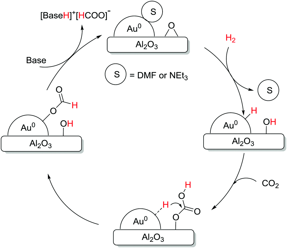
The Pidko group compared several unsupported and supported Au nanoparticles (NPs) towards CO2 hydrogenation, and, again, a higher efficiency per unit mass of Au was observed with the supported system under 40 bar equimolar pressure in EtOH using NEt3 at 40 °C.123 A variety of supports, e.g. Al2O3, TiO2, CeO2, ZnO, MgCr-HT, MgAl-HT (hydrotalcite), and CuCr2O4, were screened and Au NP/Al2O3 displayed the best reactivity with a TON of 215, presumably due to the cooperative effect between Au0 NPs and the basic Al2O3. Kinetic modelling and temperature dependent TOF studies suggested that Au NP/Al2O3 had a near-zero apparent activation energy (1.2 kcal mol−1). A plausible mechanism according to spectroscopic analysis suggests initial heterolytic dissociation of H2 at the Au/support interface to induce the formation of surface hydroxyl and Au–H species (Fig. 17). CO2 is then adsorbed on the surface to form the surface bicarbonate intermediate, which further reacts with Au–H to afford an Au–formate intermediate. This species subsequently migrates to the thermodynamically more stable alumina surface and the successive elimination of formate closes the catalytic cycle.
 | ||
| Fig. 17 Mechanistic pathway of CO2 hydrogenation over supported Au nanoparticles. | ||
Liu, Wang, Huang and co-workers used a Schiff-base-modified Au nanocatalyst supported on SiO2 towards CO2 hydrogenation. Very high activity with a maximum TON of 14470 was achieved over 12 h in H2O/MeOH at 90 °C.124 HAADF-STEM (high-angle annular dark-field scanning transmission electron microscopy) analysis confirmed that the gold species existed primarily as sub-nanoclusters with sizes of 1.4 nm along with single atoms of a lower fraction. Computational investigations were conducted to evaluate plausible catalytic pathways (Fig. 18a). The activated H species were generated via dissociation of H2 with a barrier of 0.67 eV (TS-1) and a weak exothermic contribution (∼0.10 eV). In the subsequent step, the CO2 molecule is captured as a zwitterion intermediate on the interface of the gold nanocluster and Schiff base, which is further hydrogenated to an HCO2 intermediate by activated H through TS-2 with a barrier of 1.00 eV as the rate-limiting step. The HCO2 moiety is then readily hydrogenated to cis-HCOOH by another surface H species viaTS-3 with an energy barrier of 0.58 eV, which is subsequently released from the catalyst surface leading to the product. Based on computational analysis and a kinetic study, a mechanism was proposed (Fig. 18b). In the initial step, CO2 activation is achieved through a weakly bonded carbamate zwitterion intermediate at the gold–Schiff base interface. Simultaneously, H2 dissociation is promoted by the low-coordinated sites of the gold nanoclusters to generate the activated hydride species. Finally, the carbamate zwitterion intermediates are hydrogenated by the hydride species at the gold–Schiff base interface, and product formate is thus formed after two-step hydrogenation and acid–base neutralization in basic medium.
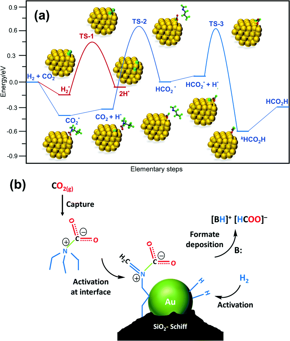 | ||
| Fig. 18 (a) Free energy diagram for CO2 hydrogenation over the Au/SiO2–Schiff catalyst. The energy profile was constructed based on the DFT calculation analysis of each elementary step. (b) Proposed synergistic mechanism for the hydrogenation of CO2 to formate in the presence of carbamate over the Au/SiO2–Schiff catalyst.124 | ||
In 2015, Lin et al. found that the hydrogenation of carbonates (Na2CO3, K2CO3 and (NH4)2CO3) was sluggish compared to that of bicarbonates (NaHCO3, KHCO3 and NH4HCO3).125 Using porous carbon material (activated carbon, AC) supported Pd as the catalyst, a higher yield of 42.4% with a TON of 782 was observed for NH4HCO3, compared to NaHCO3 and KHCO3 under 2.75 MPa H2 at ambient temperature. Controlled studies suggested that even using CO2, HCO3− was the actual substrate in the catalytic cycle. Thus, the trend of the observed reactivity was rationalized by the higher equilibrium concentration of HCO3− ions (0.92 M) over CO32− ions for NH4HCO3 than that of NaHCO3 (0.61 M) or KHCO3 (0.89 M). However, increasing the temperature had a detrimental effect owing to the Pd/AC promoted decomposition of NH4HCO3 back into CO2, H2 and NH3. Cao and co-workers evaluated the catalytic performance of Pd NPs supported on reduced graphite oxide nanosheets (Pd/r-GO) for reversible (de)hydrogenation between KHCO3 and HCOOK.126 The highest TON of 7088 was observed using 1 wt% Pd/r-GO under 4 MPa H2 at 100 °C after 32 h. However, upon increasing the catalyst loading, the catalytic efficiency gradually decreased due to the larger lattice strain of Pd NPs in 1 wt% Pd/r-GO than those in 2 and 5 wt% Pd/r-GO. The Song and Gai group employed chitin supported Pd NPs to hydrogenate aqueous Na2CO3.127 Under 40 bar H2/CO2 (1:1) at 60 °C, FA was produced with a TOF of 257 h−1.
The existence of hydroxyl groups on the surface of the support is proposed to enhance the overall catalytic performance by improving the CO2 adsorption.128 The Wang and Ma group has prepared Ru catalysts on various supports and shown that the reactivity followed the order of Ru/MgO (no activity) < Ru/AC (TON of 10) < Ru/γ-Al2O3 (TON of 91) under 13.5 MPa H2/CO2 (5/8.5) in EtOH/NEt3 at 80 °C, since γ-Al2O3 has more hydroxyl groups on the surface. The presence of RuO2 during catalyst preparation was found to have a detrimental effect on the activity. They further examined Ru-DBU/Al2O3 for hydrogenation of scCO2 under 15 MPa H2/CO2 (2:3) in the presence of NEt3 at 80 °C to achieve a maximum TOF of 239 h−1.129 Liu et al. later applied γ-Al2O3 nanorods (γ-Al2O3(n)) as a support and obtained superior reactivity with a TON of 731 compared to that of Ru/γ-Al2O3 under otherwise similar reaction conditions.130,131 The high surface area with abundant hydroxyl groups likely increased the interactions with the Ru species to offer improved activity. The Mori and Yamashita group used layered double hydroxides (LDHs) as the support to prepare single-atom Ru catalysts and achieved a maximum TON of 698 under 2 MPa H2/CO2 (1:1) at 100 °C with a Mg2+/Al3+ ratio of 5 in the LDH.132 The catalytic activity was significantly influenced by the CO2 adsorption capacity in the vicinity of the Ru center.
Mu and co-workers reported nano-Ni as an efficient catalyst for FA synthesis using 1 mM NaHCO3.133 The reaction pathway was elucidated by DFT calculations to involve the attack of active H to C of HCO3− (Fig. 19) and subsequent removal of the hydroxyl group from the bicarbonate moiety. Finally, the remaining active site of H2 combines with the hydroxyl group to produce water along with FA.
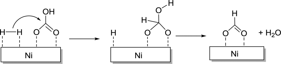 | ||
| Fig. 19 Pathways of the CO2 reduction process on Ni nanoclusters in aqueous solutions. | ||
Nguyen et al. explored bimetallic synergism towards CO2 hydrogenation. Employing carbon nanotube–graphene supported PdNi alloys (PdNi/CNT–GR), base free FA synthesis was achieved.134 The choice of the composite support materials was determined in order to avoid the stacking of GR and bundling of CNTs. Applying bimetallic PdNi/CNT–GR (Pd3Ni7/CNT–GR; Pd – 30%, Ni – 70%), 1.92 mmol of FA was generated along with a trace amount of acetic acid under 5 MPa H2/CO2 (1:1) at 40 °C, albeit with a small TON of 6.4. The fact that mono-metallic counterparts Pd/CNT–GR and Ni/CNT–GR both exhibited poorer catalytic efficiency suggested plausible bimetallic cooperativity. Later, Mori, Yamashita and co-workers also synthesized a series of catalysts comprising PdAg NPs supported on resorcinol-formaldehyde polymers having variable amine contents (PdAg/amine-RFX).135 Employment of the support with the highest amine concentration resulted in a maximum TON of 867 towards FA synthesis, which was around 10 times higher than that of monometallic Pd/amine-RFX, again suggesting the importance of bimetallic cooperativity. Very recently, the Yu and Yan group has demonstrated zeolite-encaged Pd–Mn nanocatalysts (PdMnX@S-1) for efficient CO2 hydrogenation to formate.136 With catalyst PdMn0.6@S-1, the highest formate generation rate of 382 molformate molPd−1 h−1 was achieved at room temperature with a TOF of 466 h−1. This was around 2-fold higher than that of catalyst Pd@S-1. This superior reactivity was attributed to the bimetallic synergism between Pd and Mn species, which increases the electron density on Pd surfaces and in turn improves the reaction rate. The important results discussed in Sections 2.2.1 and 2.2.2 have been summarized in Table 5.
| Catalyst precursor | Solvent | Base/additive | H2/CO2 (bar) | Temp. (°C) | TON | TOF (h−1) | Ref. |
|---|---|---|---|---|---|---|---|
| Pd bulk | H2O | KHCO3 | 60/0 | 70 | 5 | 0.22 | 113 |
| Pd bulk | H2O | NaHCO3 | 1/0 | RT | 2.1 | 0.02 | 115 |
| Ni/Fe powder | H2O | K2CO3 | 0/11 | 300 | 0.022 | 0.01 | 116 |
| Ru NPs | [DAMI][OTf] | NA | 250/250 | 50 | 19862 |
9931 | 118 |
| Ru NPs | [DAMI][OTf] | H2O | 250/250 | 50 | 24545 |
4909 | 118 |
| Ru NPs | scCO2 | NEt3/H2O | 50/130 | 80 | 6351 | 2117 | 119 |
| NiNPore | H2O | NaHCO3 | 60/0 | 200 | 3476 | 1738 | 120 |
| Pd/C | [Bmim][OAc] | NA | 50/30 | 40 | 594 | NA | 121 |
| Pd NP/C | H2O | NaHCO3 | 1.7/0 | RT | 115 | 25 | 115 |
| Au (AUROlite)/TiO2 | NEt3 | NEt3 | 90/90 | 40 | 855 | 16.4 | 117 |
| Au/SiO2–Schiff | H2O/CH3OH | NEt3 | 50/30 | 90 | 14470 |
1206 | 124 |
| Au NP/MgAl-HT | EtOH | NEt3 | 20/20 | 70 | 91 | 4.5 | 123 |
| Au NP/TiO2 | EtOH | NEt3 | 20/20 | 70 | 111 | 5.5 | 123 |
| Au NP/Al2O3 | EtOH | NEt3 | 20/20 | 70 | 215 | 11 | 123 |
| Ru/AC | EtOH | NEt3 | 50/85 | 80 | 10 | 10 | 128 |
| Ru/γ-Al2O3 | EtOH | NEt3 | 50/85 | 80 | 91 | 91 | 128 |
| Ru-DBU/Al2O3 | DMSO | NEt3/KH2PO4 | 60/90 | 80 | NA | 239 | 129 |
| Ru/γ-Al2O3(n) | EtOH | NEt3 | 50/85 | 80 | 731 | 731 | 130 |
| Ru/LDH | H2O | NaOH | 10/10 | 100 | 698 | 29 | 132 |
| PdAg/amine-RFX | H2O | NaHCO3 | 10/10 | 100 | 867 | NA | 135 |
| Pd/AC | H2O | NaHCO3 | 27.5/0 | RT | 527 | 527 | 125 |
| Pd/AC | H2O | KHCO3 | 27.5/0 | RT | 567 | 567 | 125 |
| Pd/AC | H2O | NH4HCO3 | 27.5/0 | RT | 782 | 782 | 125 |
| Pd/r-GO (1 wt%) | H2O | KHCO3 | 40/0 | 100 | 7088 | 221 | 126 |
| Pd/r-GO (5 wt%) | H2O | KHCO3 | 40/0 | 100 | 1658 | 165 | 126 |
| Pd NP/chitin | H2O | Na2CO3 | 20/20 | 60 | NA | 257 | 127 |
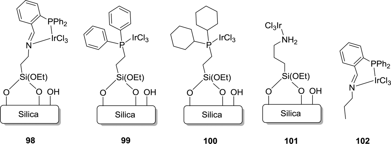
2.2.3.1 Grafted molecular catalysts. Mesoporous silica supported immobilized Ir complexes (98–101) for CO2 hydrogenation were first reported by Hicks and co-workers (Fig. 20).137 Among several grafted complexes (98–101) and the homogeneous analog (102), catalysts having a phosphine backbone (98–100 and 102) were found to be active (Fig. 20). Using catalyst 98, a TON of 1300 was obtained under 4 MPa H2/CO2 (1
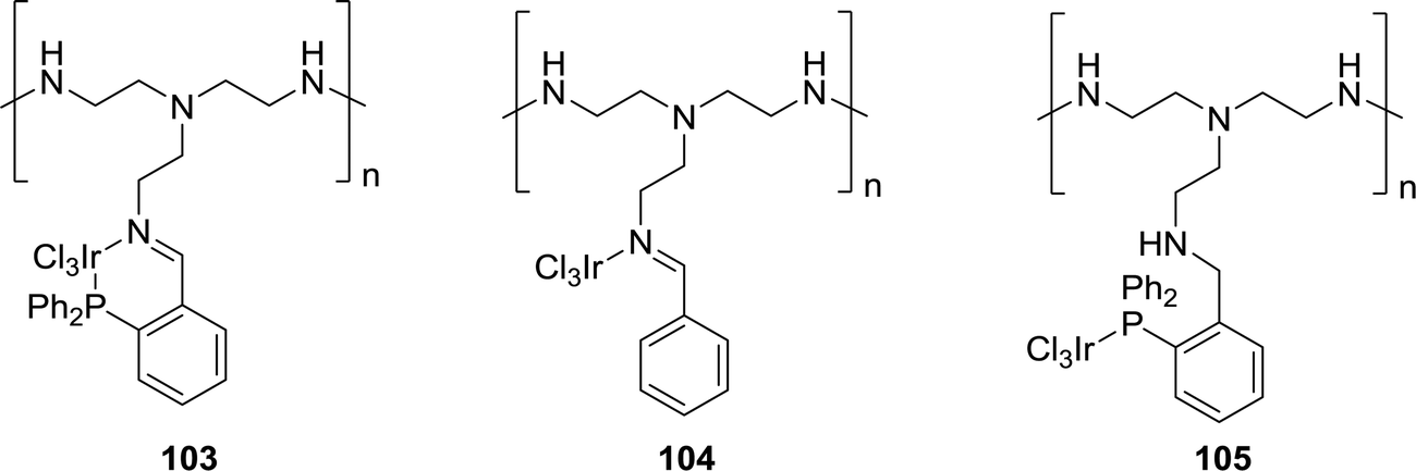
:1) in the presence of NEt3 as the base in H2O at 60 °C after 2 h. Under similar reaction conditions, the rest of the catalysts performed poorly, e.g.99, 100 and 102 with TONs of 110, 400, and 70, respectively. Continuing the reaction for a longer time (20 h) and elevating the temperature to 120 °C resulted in higher TONs of 2700 and 2300, respectively, for 98. X-ray photoelectron spectroscopy (XPS) revealed similar environments around Ir metal in 98 (61.6 eV) and 102 (61.8 eV), but such a substantial difference in catalytic activity suggested the improved stability and activity of the homogeneous system upon heterogenization. The Hicks group further explored polyethyleneimine (PEI), an aliphatic amine-based organic polymer containing primary, secondary and tertiary amine groups, as a support (Fig. 21).138 Such materials have the unique property to stabilize formate and act as a CO2 capturing agent. Imine containing catalyst 104 exhibited superior activity compared to catalyst 103, generated by tethering complex 102 on PEI, and catalyst 105, having a phosphine backbone. Interestingly, increasing the Ir loading on the PEI backbone had a significant effect on the reactivity. Ir-25% (PEI-PN/Ir-25) exhibited a reduced TOF of 94 h−1 compared to Ir-65% (PEI-PN/Ir-65) with a TOF of 310 h−1, likely due to the existence of agglomerated Ir NPs as confirmed by XPS and TEM. Furthermore, the catalyst efficacy decreased during the recycling experiments, particularly for low molecular weight PEI catalysts, due to the increased solubility.
 | ||
| Fig. 20 Examples of grafted Ir catalysts. | ||
 | ||
| Fig. 21 Polyethyleneimine (PEI) supported Ir catalysts. | ||
Yamashita and co-workers reported a PEI-tethered Ir–iminophosphine complex (Ir–PN–PEI) immobilized in titanate nanotubes (TNTs), Ir–PN–PEI@TNT, for CO2 hydrogenation (Fig. 22).139 Using Na+ type TNT, the resultant Ir–PN–PEI@TNT(Na+) (106) afforded continuous FA production over 20 h with a TON of 1012 under 2.0 MPa H2/CO2 (1:1) at 140 °C. Comprehensive structural analyses suggested that these TNTs provided tight interactions of the active components with the support. CO2 adsorption measurements and kinetic studies indicated that the ability of the TNTs to strongly stabilize the polymer species and to adsorb/condense CO2 molecules in the vicinity of the active Ir centre is the key to its catalytic performance.
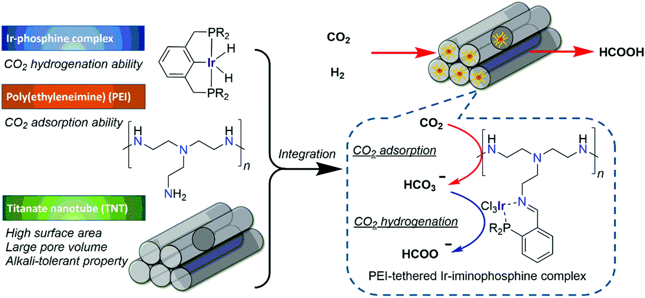 | ||
| Fig. 22 Schematic illustration of Ir–PN–PEI@TNT(Na+) 106 mediated CO2 hydrogenation.139 | ||
Zheng and co-workers extensively examined the effect of various supports and the donor atoms for CO2 hydrogenation to FA/formate.140–144 A variety of immobilized Ru complexes with silica, mesoporous MCM-41, and polystyrene as the support and different functional donor groups, such as CN, SH and NR2, were investigated (107–116; Fig. 23). Under 14.7 MPa H2/CO2 (5.4/9.3) in EtOH using NEt3 as the base and PPh3 as an additive at 80 °C, the amine functionalized MCM-41 support (107, TON = 1022) exhibited better activity than those of the nitrile (108, TON = 723) and thiol (109, TON = 537) functionalities. This trend was attributed to the stronger electron donating ability of amine groups to metal ions. Interestingly, during recycling studies, catalyst 109 retained its integrity for a longer time than catalysts 107 and 108, which deactivated faster. This robustness was due to a better back donating ability of the SH group than the CN and NR2 donors. 107 also displayed better reactivity than that of silica supported 110 (TON of 656), due to the high surface area (852 m2 g−1) and the uniform pore size (3.5 nm) of MCM-41. Catalyst 110 having the organic support polystyrene displayed somewhat poorer activity with a TON of 151 under otherwise similar reaction conditions. Among various amine functionalized silica supported catalysts, 112 containing secondary amine groups was more active with a TON of 1384 compared to 110 (TON of 656) and 113 (TON of 868). Similarly, catalyst 111 performed slightly better with a TON of 151 than 114 (TON of 75) and 115 (TON of 143). These observations indicated that the catalyst efficacy depends sensitively on the electron donating ability of the ligands. It was proposed that the octahedral dihydrido Ru 116 may serve as the active catalytic species in these reactions. Inspired by the work of Zhang, Han et al. prepared a molecular heterogeneous pre-catalyst “Si”–(CH2)3NH(CSCH3)–[RuCl3–PPh3] (117) supported with silica and polystyrene. The precatalyst was synthesized by mixing RuCl3·3H2O and “Si”–(CH2)3NH(CSCH3) with subsequent addition of the PPh3 ligand.145 Amine functionalized ILs were used as a reusable base during this process. The resulting formate salt and catalyst could easily be separated by filtration. Using 117 and the IL under 18 MPa H2/CO2 (1:1) gave a maximum TOF of 103 h−1 at 60 °C. Subsequently, diamine-functionalized ILs were also employed to enhance the TOF to 920 h−1 under 18 MPa H2/CO2 (1:1) at 80 °C.146
 | ||
| Fig. 23 Examples of grafted Ru catalysts with various supports and functional groups. | ||
2.2.3.2 Heterogenized porous polymers. Considering the high surface area and well defined porosity of porous organic frameworks, they were explored as potential catalyst supports to outperform silica, polystyrene and aliphatic polymer supports.147,148 Liu and co-workers synthesized a Tröger's base-derived microporous organic polymer (TB-MOP) supported Ru catalyst TBMOP–Ru (118) by coordination bonding between the Ru ions and the N atoms of the TB-MOP (Fig. 24).149 The microporous structure was confirmed by Brunauer–Emmett–Teller (BET) measurements. Under 12 MPa H2/CO2 (1
:1) in the presence of NEt3 as the base and PPh3 as the additive, decent activity was achieved with a TON of 2254 at 40 °C after 24 h. The activity significantly dropped in the absence of PPh3, suggesting that PPh3 may mediate in situ generation of the active catalytic species. Moreover, during the recycling studies, catalyst leaching (detected by ICP-OES) occurred, and a reduced TON was observed from the second cycle onwards. This was attributed to the weaker complex forming ability of the Tröger's base compared to PPh3.
 | ||
| Fig. 24 Structural representation of catalyst 118. | ||
The pioneering work of Himeda on homogeneous Cp*Ir catalysts has set a benchmark for other systems to achieve comparable reactivities. The Yoon group developed a procedure to immobilize complex 22 within a covalent triazine framework (CTF) (Fig. 25).150 bpy incorporated CFT (bpy–CTF) was treated with [IrCp*Cl2]2 to afford a heterogenized material, bpy–CTF–[IrCp*Cl]Cl (119). XPS measurements of 119 and its homogeneous analog revealed an identical binding energy for Ir 4f7/2 (62.1 eV), indicative of a similar coordination environment around the Ir center. This was further confirmed by SEM, illustrating a uniform distribution of Ir and Cl atoms throughout the material. Moreover, EDS and XPS studies supported that the atomic ratio of Cl and Ir was close to 2. Detailed analysis of ICP-MS revealed a relatively high Ir content (4.7 wt%) in the framework, suggesting the presence of one [IrCp*] unit for every sixth CTF ring. Under 4 MPa H2/CO2 (1:1), 119 gave a TON of 500 in the presence of NEt3 in H2O at 80 °C after 2 h. A TON of 3320 was achieved by increasing the temperature to 120 °C, but a higher temperature, 160 °C, led to a decrease in the activity (TON = 2720). Such observations were well correlated to the exothermic nature of the reaction. Moreover, a maximum TON of 5000 was achieved when the total pressure of H2/CO2 was increased to 8 MPa at 120 °C. 119 was reused with no substantial loss of activity for up to five runs.
 | ||
| Fig. 25 Structural illustration of catalyst 119. | ||
Most of the above mentioned catalytic tests were performed under batch conditions but Urakawa et al. demonstrated a continuous synthesis of FA and methyl formate using DCP–CTF–[IrCp*Cl]Cl (120) (DCP = 2,6-dicyanopyridine) (Fig. 26).151 The microporous structure was confirmed by BET measurements (surface area of 734 m2 g−1) and STEM and EDX analyses further indicated the homogeneous dispersion of Ir in the matrix. When the reaction mixture (H2:CO2:S = 4:4:1 molar ratio, S = MeOH, H2O, NEt3) was introduced into the reactor containing 120 at 300 bar at 100 or 180 °C, weight time yields of 5.4–385.5 mgFAgIr−1 h−1 were achieved. In situ vibrational spectroscopy revealed that strong interactions of CO2 and H2 with CTF may account for its stability even under harsh supercritical and flow conditions.
 | ||
| Fig. 26 Structural representation of catalyst 120. | ||
Yoon and co-workers further immobilized [IrCp*Cl2]2 onto graphitic carbon nitride (g-C3N4) (121) and a heptazine-based framework (HBF) (122) (Fig. 27).152 EDS measurements revealed the ratio of Ir to Cl as 1:2 and SEM analysis suggested uniform metalation. ICP-MS analysis of 122 revealed a very low Ir content (0.86 wt%) in the framework. Under a total pressure of 8 MPa, 122 afforded a TON of 6400 in H2O at 120 °C after 10 h in the presence of NEt3. 122 could be recycled for five runs without any substantial loss of activity and, in each run, 90% catalytic activity was retained with an average TON of 4000.
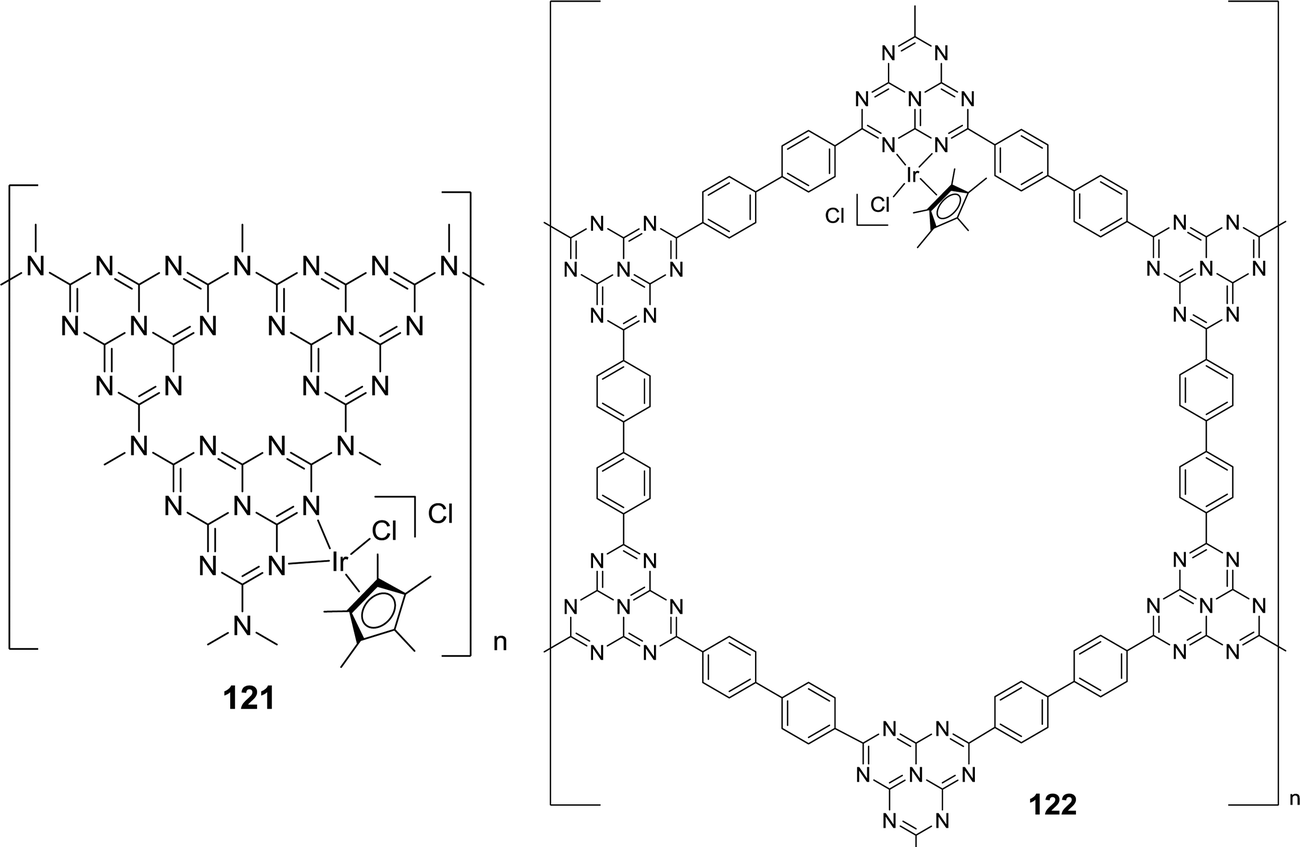 | ||
| Fig. 27 Structural representation of catalysts 121 and 122. | ||
Yoon et al. also grafted Ru(acac)2 onto CTF and synthesized an analogous material to 119, [bpy–CTF–Ru(acac)2]Cl (123) (Fig. 28). A maximum initial TOF of 22700 h−1 was achieved under 8 MPa H2/CO2 (1:1) at 120 °C.153123 was recycled for 4 consecutive runs and the catalyst integrity was maintained throughout the reactions as confirmed by SEM-EDS mapping and XPS analysis. When RuCl3·xH2O was grafted onto the same support, the resulting [bpy–CTFRuCl3] (124) gave an initial TOF of 38800 h−1 and produced formate in the presence of NEt3 with a final concentration of 2.05 M in 2.5 h (Fig. 28).154124 was also reused over 5 cycles without loss of activity.
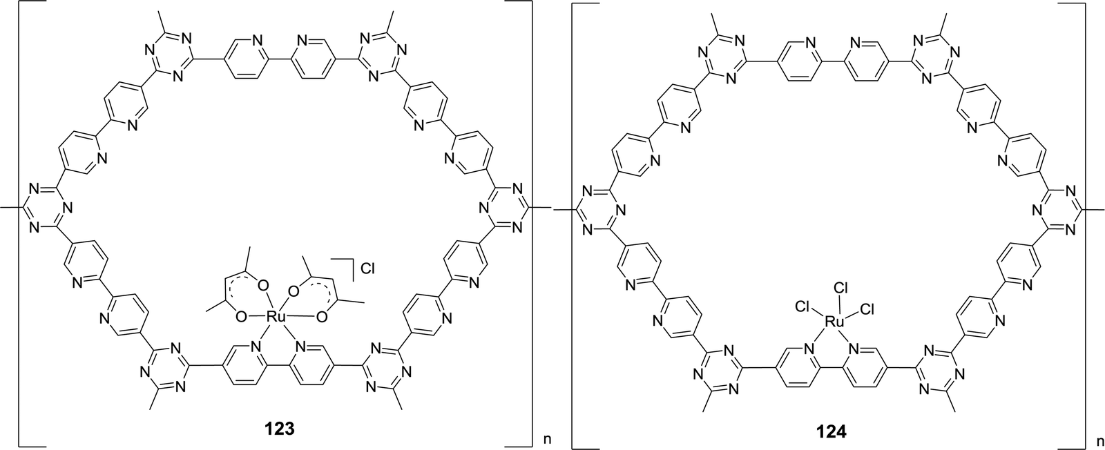 | ||
| Fig. 28 Structural representation of catalysts 123 and 124. | ||
The Yoon group also exploited mesoporous g-C3N4 as the support for Pd NPs (Pd/mpg-C3N4) (125) and studied CO2 hydrogenation.155 Under 4 MPa H2/CO2 (1:1) in a 20% NEt3/D2O solution at 150 °C, Pd/mpg-C3N4 afforded a TON of 81 after 24 h. Keeping the other parameters fixed but increasing p(H2)/p(CO2) to 2 resulted in an enhanced TON of 106. Later, Mondelli, Pérez-Ramírez, and co-workers studied a bifunctional catalyst comprising Pd NPs deposited on bulk g-C3N4 under base-free conditions for FA production.156 The Pd metal provided the necessary redox sites for H2 splitting, whereas the basic amino groups of the support were involved in CO2 activation. Thermal exfoliation, hard-templating and carbon enrichment were performed to maximize the edge-defects of the g-C3N4 carrier, which in turn enhanced the catalyst productivity. Subsequently, the Huang and the Liang groups developed a mesoporous Pd catalyst (Pd/u-CN100) (126) tethered on Schiff base modified graphitic carbon nitride having a high surface area (Fig. 29).157 Grafting of an appropriate amount of terephthalaldehyde (TPAL) into the support led to scattered Schiff base and multiple nitrogen based species. These had a significant impact on the high dispersion of Pd nanoclusters, electronic environment and a large promotion of the material surface area and volume, which in turn influenced the catalytic efficiency. Under 7 MPa H2/CO2 (1:1), 126 afforded a maximum TOF of 98.9 h−1 at 110 °C in EtOH.
 | ||
| Fig. 29 Schiff base modified Pd/u-CN100 (126) catalyst for CO2 hydrogenation.157 | ||
The Palkovits group reported cross-linked polyphosphine (pdppe) as a support for [(Ru(p-cymene)Cl2)2] for CO2 hydrogenation to formate (Fig. 30).158 The XPS measurement of the resulting Ru@pdppe (127) confirmed the oxidation state of Ru as +2 and the TEM analysis revealed the absence of any NPs. Under 100 bar H2/CO2 (1:1) in the presence of K2CO3 in water, a maximum TON of 13170 was observed at 120 °C. Recycling studies were performed for up to eight runs; however, a significant deactivation was observed after the first cycle, due to the structural changes of the metal complex.
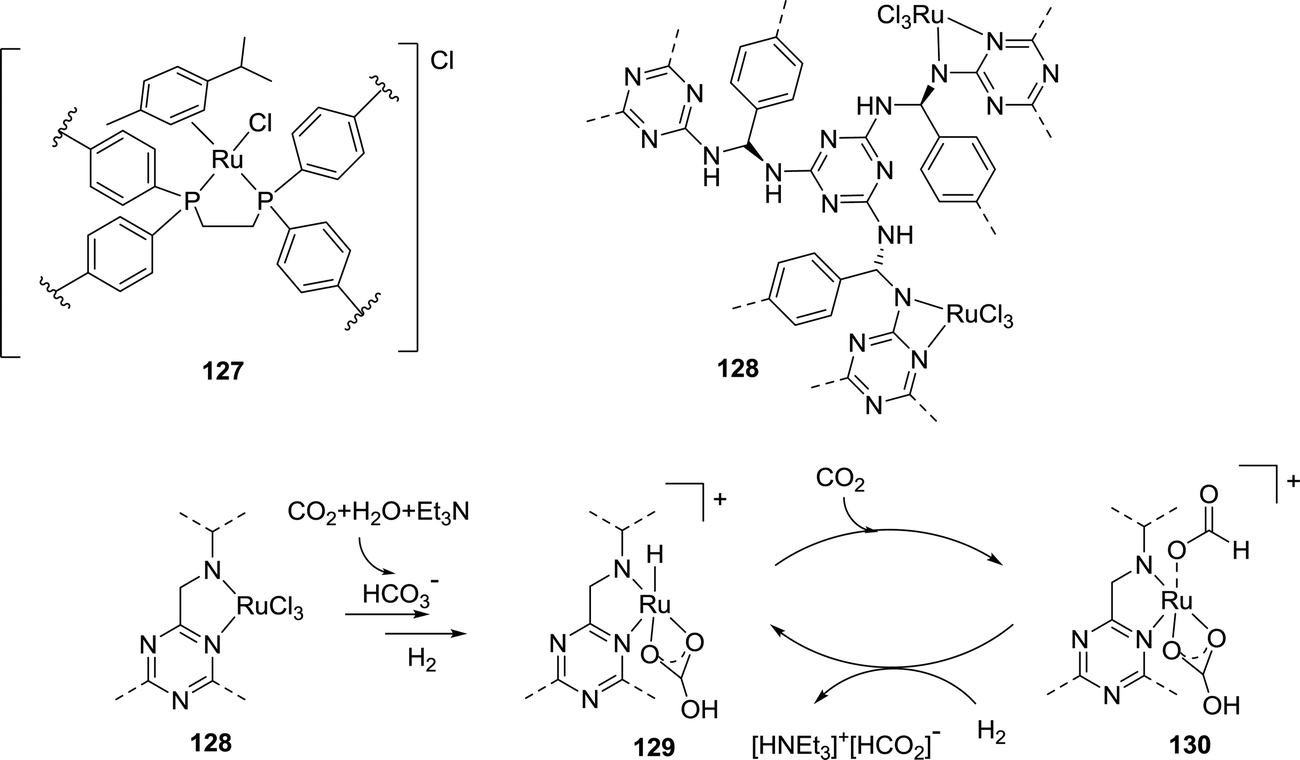 | ||
| Fig. 30 Structural representation of 127 and 128, and the proposed mechanism of CO2 hydrogenation by 128. | ||
Recently, Jung et al. employed a melamine polymer-network (MPN) as the support for grafting RuCl3·xH2O to prepare Ru@MPN (128) (Fig. 30).159 Under 80 bar H2/CO2 (1:1), 128 afforded a maximum TON of 4706 in H2O at 120 °C after 12 h in the presence of NEt3. From experimental observations, a mechanism was proposed where HCO3−, generated by the reaction of CO2 and H2O in the presence of NEt3, replaces the metal coordinated chloride. It is followed by the reaction with H2 to generate a Ru–H intermediate as the active catalytic species (129) (Fig. 30). CO2 can then be inserted into the Ru–H bond to generate a metal coordinated formate species (130; Fig. 30). 129 is regenerated by base mediated heterolytic H2 splitting.
Metal organic frameworks (MOFs) could also serve as a potential candidate for supports for metal precursors. In 2017, Cheng, Wang, Lin and co-workers for the first time prepared MOF supported Ir based catalysts mbpyOH-Ir-UiO (131) and mbpy-Ir-UiO (132) for CO2 hydrogenation.160 Under 0.1 MPa H2/CO2 (1:1) in 1 M NaHCO3 aqueous solution at 85 °C, 131 gave a better TON of 6149 than that of 132 (TON = 417). Experimentally observed high kinetic isotope effect (KIE) value of 140 suggested the involvement of a concerted proton–hydride shuttle in the rate-determining step of the reaction. A thorough computational analysis revealed the energetics of the transition states associated with the H2 heterolysis and proton–hydride transfer steps with corresponding activation energies of 0.34 kcal mol−1 and 16.26 kcal mol−1, respectively. This observation further suggested that the proton–hydride transfer is the rate limiting step of the process. Wang et al. immobilized Ru complexes, such as RuCl3, [Cp*RuCl2]2 and [Ru(C6Me6)Cl2]2, on an azolium based MOF to prepare Ru–NHC-MOF catalysts 133–135, respectively.161 Catalyst 135 was found to be the most efficient among them owing to the presence of the strong electron-donating C6Me6 ligand. Using K2CO3 as an inorganic salt additive and DMF as the solvent, a TON up to 3803 was achieved under 8 MPa H2/CO2 (1:1) at 120 °C. A summary of selected heterogenized catalysts for CO2 hydrogenation is provided in Table 6.
| Catalyst precursor | Solvent | Base/additive | H2/CO2 (bar) | Temp. (°C) | TON | TOF (h−1) | Ref. |
|---|---|---|---|---|---|---|---|
| 98 | H2O | NEt3 | 20/20 | 60 | 1300 | 620 | 137 |
| 100 | H2O | NEt3 | 20/20 | 60 | 400 | 200 | 137 |
| 98 | H2O | NEt3 | 20/20 | 120 | 2300 | 1200 | 137 |
| 98 | H2O | NEt3 | 20/20 | 60 | 2700 | 140 | 137 |
| 103 | H2O | NEt3 | 20/20 | 120 | 248 | 248 | 138 |
| Ir–PN–PEI@TNT(Na+) (106) | H2O | NaOH | 10/10 | 140 | 1012 | 50.6 | 139 |
| 107 | EtOH | PPh3/NEt3 | 54/93 | 80 | 1022 | 1022 | 142 |
| 110 | EtOH | PPh3/NEt3 | 40/120 | 80 | 656 | 656 | 140 |
| 111 | EtOH | PPh3/NEt3 | 50/80 | 80 | 151 | 151 | 142 |
| 108 | EtOH | PPh3/NEt3 | 54/93 | 80 | 723 | 723 | 142 |
| 112 | EtOH | PPh3/NEt3 | 54/93 | 80 | 1384 | 1384 | 142 |
| 113 | EtOH | PPh3/NEt3 | 40/120 | 80 | 868 | 868 | 140 |
| 109 | EtOH | PPh3/NEt3 | 40/120 | 80 | 537 | 537 | 140 |
| 117 | H2O | [mammim][TfO]/PPh3 | 90/90 | 60 | 206 | 103 | 145 |
| 117 | H2O | [DAMI][TfO]/PPh3 | 40/120 | 80 | 1840 | 920 | 146 |
| TBMOP–Ru (118) | NEt3 | PPh3 | 60/60 | 60 | 2254 | 94 | 149 |
| (Pd/mpg-C3N4) (125) | D2O | NEt3 | 27/13 | 150 | 106 | 4.4 | 155 |
| bpy–CTF– [IrCp*Cl]Cl (119) | H2O | NEt3 | 20/20 | 120 | 3320 | 1660 | 150 |
| bpy–CTF– [IrCp*Cl]Cl (119) | H2O | NEt3 | 40/40 | 120 | 5000 | 5300 | 150 |
| [bpy–CTF–Ru(acac)2]Cl (123) | H 2 O | NEt 3 | 40/40 | 120 |
21200
|
22700
|
153 |
| [bpy–CTFRuCl3] (124) | H 2 O | NEt 3 | 40/40 | 120 |
20000
|
38800
|
154 |
| 122 | H2O | NEt3 | 40/40 | 120 | 6400 | 1500 | 152 |
| Ru@pdppe (127) | H2O | K2CO3 | 50/50 | 120 | 13170 |
3290 | 158 |
| Ru@MPN (128) | H2O | NEt3 | 40/40 | 120 | 4706 | 4964 | 159 |
| mbpyOH-Ir-UiO (131) | H2O | NaHCO3 | 0.5/0.5 | 85 | 6149 | 410 | 160 |
| mbpy-Ir-UiO (132) | H2O | NaHCO3 | 0.5/0.5 | 85 | 427 | 28 | 160 |
| 133 | EtOH | NEt3 | 40/40 | 120 | 313 | 156 | 161 |
| 134 | EtOH | NEt3 | 40/40 | 120 | 454 | 227 | 161 |
| 135 | DMF | NEt3 | 40/40 | 120 | 3803 | 1900 | 161 |
2.3. Economic feasibility of CO2 hydrogenation catalysts
The parameters of catalytic activity above evidently indicate that homogeneous catalytic systems mostly outperform heterogeneous catalysts. Although the catalytic efficiencies are commonly characterized by their TON and TOF values, determining their practical applicability is not so straightforward and consideration based on economic parameters is necessary. To assess such a situation, we have previously introduced a dimension-free key-parameter to normalize the catalyst costs based on the TON. The “catalyst price normalized to TON” (CON, eqn (3)) describes the contribution of the catalyst in the cost of the product, formic acid.12,19 Hence, a large TON value and a low production cost of the catalyst are advantageous. Any CON value greater than 1 suggests that the catalyst is more expensive than the product and will not be suitable for large scale application. For FA manufacturing, TOFs are less relevant, but it should be noted that a catalyst with a low TOF will require a larger reactor to achieve similar productivity to that of catalysts with high TOFs; thus, a potentially higher investment in the infrastructure may be needed.| CON = (Pcat/TON)KProd | (3) |
 where Mwcat is the molecular weight of the catalyst, MwProd is the molecular weight of the product,
  is the target price of the product per kg, and Pcat is the price of the catalyst per kg.
Seven high performance homogeneous and two heterogeneous catalytic systems with reasonably high TON values were selected for the CON analysis (Fig. 31). The corresponding CON values were calculated for large industrial scale FA production using eqn (3) assuming a base price of $600 tonFA−1 (per ton of FA) and a 90% reduction in the catalyst cost from the lab scale (Table 7). It is understandable that low CON values are necessary for economic feasibility. Unfortunately, it is evident that most of the catalysts, except 41, are not suitable for practical applications just based on the large CON values. It becomes even more challenging if a target base price of $300 tonFA−1 is assumed. One also notes that the condition to achieve a high TON for 41, with a catalyst loading of 0.0010 μmol, may compromise the productivity. The reaction conditions should also be taken into account to justify whether the process is realistic to be ventured.
 | ||
| Fig. 31 Representative examples of catalysts chosen for CON calculations during CO2 hydrogenation. | ||
| Catalyst | Reaction conditions | TON | Costa ($ per mole) | CON |
|---|---|---|---|---|
| a The cost estimation was calculated based on commercial prices of available starting materials based on the same reaction procedures and yields reported in individual literature. Since solvent and manpower costs were not taken into account, these values should be used for preliminary economic evaluation only. | ||||
| 21 | In H2O at 120 °C | 190000 |
311000 |
5.93 |
| 32 | In H2O at 200 °C | 190000 |
87000 |
1.66 |
| 41 | In H2O/THF at 200 °C | 300000 |
161000 |
1.94 |
| 41 | In H2O/THF at 120 °C | 3500000 |
161000 |
0.17 |
| 44 | In H2O at 185 °C | 348000 |
204000 |
2.12 |
| 48 | In DMF at 120 °C | 200000 |
97000 |
1.76 |
| 79 | In THF at 80 °C | 58990 |
18000 |
1.12 |
| 82 | In THF at 80 °C | 46100 |
22000 |
1.76 |
| 123 | In H2O at 120 °C | 21200 |
87000 |
14.79 |
| 124 | In H2O at 120 °C | 20000 |
86000 |
15.59 |
3. Electrochemical reduction of carbon dioxide
The electrochemical CO2 reduction reaction (eCO2RR) using renewable energy offers a direct pathway for power-to-formic acid where CO2 is utilized as a storage medium as well as a feedstock for valuable fuels/chemicals, and this has previously been discussed in various perspectives, review articles and book chapters.162–171 Electrocatalysis has several advantages: (1) the process can be controlled by adjusting the potentials and reaction temperatures, (2) the electrolytes can be recycled in many cases, (3) the set-up is modular, compact, and easy to scale up, (4) the reaction may be conducted at room temperature and atmospheric pressure, and (5) direct use of renewable and/or low-carbon electricity is applicable. The eCO2RR is, in general, considered to involve three main steps: (1) CO2 activation by chemical adsorption of CO2 on the surface of a catalyst, (2) electron (e−) and proton (H+) transfer to break C–O bonds and/or form C–H bonds, and (3) rearrangement of the product(s) followed by desorption from the electrode surface and diffusion into the electrolyte. However, the eCO2RR faces several challenges in controlling the selectivity because the transfer of different H+ and e− equivalents may lead to divergent end-products (either liquids such as methanol and ethanol or gases such as CO, methane and ethylene) and the competing H2 evolution reaction (HER).172 Therefore, comprehensive and in-depth understanding of the thermodynamic and kinetic properties for minimizing and/or circumventing competitive pathways is critical to achieve high selectivity and energy efficiency.173Significant efforts have been devoted to probing the reaction mechanisms of electrochemical CO2-to-FA conversion with a combination of experimental results and theoretical analyses utilizing DFT studies discussed succinctly in some recent literature reports.174–177 HCOO− or HCOOH is generated possibly via an intermediate that binds to a metal electrode either through one O atom (monodentate) or two O atoms (bidentate) (Fig. 32a). This intermediate can form via CO2 insertion into metal-hydride bonds or through direct protonation with H+ from solution (Fig. 32). An alternate pathway is proposed to proceed via a CO2˙− radical that reacts readily with neighboring H2O or H+ to generate HCOO− or HCOOH (Fig. 32b). Sometimes, the presence of HCO3− was found to enhance HCOO− production eliminating CO32− in the solution (Fig. 32b). In this context, Sridhar and co-workers evaluated in their engineering and economic feasibility study that the propensity to produce either formate salt or FA with relatively low specific energy consumption and high faradaic efficiencies (FEs, eqn (4)) is higher compared to other CO2 reduction products except CO.178 The electrochemical CO2 conversion performance is often quantified via two criteria, (i) a high energy efficiency (EE) and (ii) a high reaction rate. The EE is a vital parameter because it specifies the recoverable energy contained in the product and defines the energy cost of producing the product (eqn (5)).162 A high EE is commonly achieved through a combination of high selectivity (faradaic efficiency (FE)) and low overpotential (η) (eqn (5))
 | (4) |
 | (5) |
 | ||
| Fig. 32 Possible reaction pathways for the eCO2RR to HCOO− or HCOOH via the (a) monodentate or bidentate intermediate route and (b) CO2˙− intermediate route.171,174 | ||
Although the thermodynamic potential for one electron reduction of CO2 to CO2˙− is extremely high (ca. −1.90 V vs. SHE) in aqueous solution, for ne−/nH+ (n ≥ 2) reduction to HCOOH, HCOO, HCHO, CH3OH, and CH4, these values are relatively low (Table 8). This is likely because of the involvement of proton coupled electron transfer (PCET) and multi-electron transfer pathways, leading to routes that involve low η processes.166 Similarly, due to lower energy consumption, the CO2-to-FA pathway is always favored over CO2-to-oxalic acid (H2C2O4) conversion (Table 8). These concepts are well-established in the literature and hundreds of catalytic systems have been developed in the past few decades where these ideas were successfully implemented to selectively produce formate/FA from CO2. The three most common catalyst forms for formate production are: (i) using heterogenous solid electrodes for direct reduction of CO2, (ii) using homogeneous solution electrocatalysts, and (iii) chemically modified electrodes where catalysts are immobilized (Fig. 33a).181 The direct eCO2RR on a bare heterogenous electrode surface normally requires large overpotentials, resulting from the disparity between the applied electrode potential (Eapplied) and E0(products/CO2) at a given current density (CD or j; defined as the total current per unit area of the electrode and describing the total rate of reaction). Low η and high product selectivity with a considerable reaction rate constant (Kcat) are highly desired for a catalyst having E0(catox/red) well matched to E0(products/substrates) for an ideal outcome.167 In general, for continuous CO2 reduction, the eCO2RR is accomplished in an electrolytic cell which consists of a cathode and an anode across which an electrical current or voltage is applied (Fig. 33b). These two electrodes are usually coated with catalysts and placed in chambers separated by an ion exchange membrane. A suitable solvent/electrolyte, for transferring ions, along with CO2, is introduced in the cathode chamber. This half-cell CO2 reduction is completed by the 2nd half-cell complementary oxidation reaction occurring at the anode (eqn (6) and (7)). The general cathodic and anodic reactions for the eCO2RR to FA are:
| Cathode: 2CO2 + 4H+ + 4e− → 2HCOOH | (6) |
| Anode: 2H2O → O2 + 4H+ + 4e− | (7) |
| Half-cell thermodynamic reactions | E 0 (V vs. SHE) |
|---|---|
| a This potential is in water. In DMF, the value is −1.970 vs. SHE. | |
| CO2(g) + e− → CO2˙− | −1.900a |
| CO2(g) + 2e− + 2H+ → HCOOH(l) | −0.250 |
| CO2(g) + 2e− + H2O(l) → HCOO−(aq) + OH− | −1.078 |
| CO2(g) + 2e− + 2H+ → CO(g) + H2O(l) | −0.106 |
| CO2(g) + 2e− + H2O(l) → CO(g) + 2OH− | −0.934 |
| CO2(g) + 4e− + 4H+ → CH2O(l) + H2O(l) | −0.070 |
| CO2(g) + 6e− + 6H+ → CH3OH(l) + H2O(l) | 0.016 |
| CO2(g) + 8e− + 8H+ → CH4(g) + H2O(l) | 0.169 |
| CO2(g) + 2e− + 2H+ → H2C2O4(aq) | −0.500 |
| CO2(g) + 2e− → C2O42−(aq) | −0.590 |
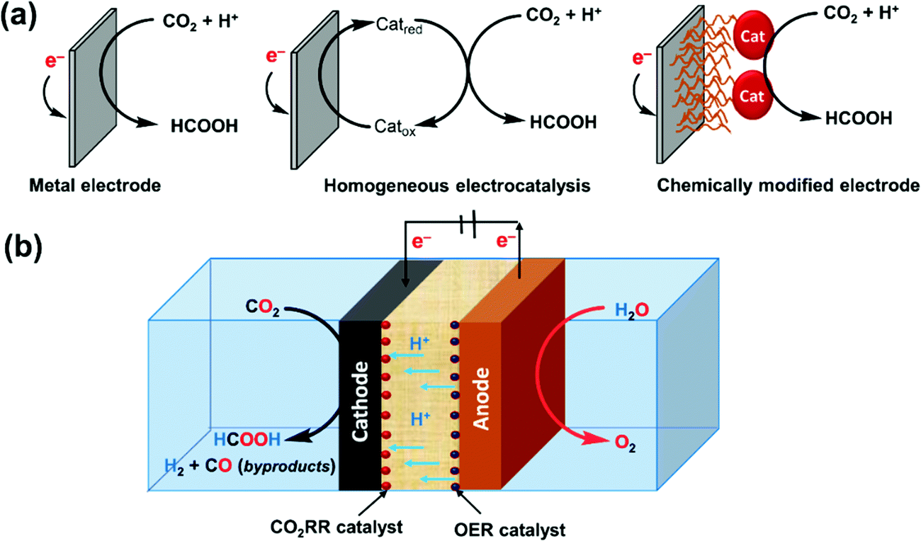 | ||
| Fig. 33 (a) Electrochemical reduction of CO2 by metal electrodes (left), homogeneous electrocatalysis (middle) and chemically modified electrodes (right). (b) Schematic representation of the electrochemical processes to convert CO2 to FA in an electrolytic cell. | ||
The factors governing the efficiency and selectivity of electrocatalytic production of FA are not only the reaction mechanisms involving various reaction intermediates, but also common factors and reaction parameters such as the solvents/electrolytes, pH of the solution, CO2 pressure of the system, electrode materials, catalysts, design of the electrochemical cell/reactors etc. In the following section of this review, these factors will be elucidated and discussed individually, mainly focusing on the FE, η, partial current density (PCD; defined as the product of FEproduct and j), and stability of the electrocatalysts. Finally, we have provided a discussion in Section 3.6 towards the development of practical systems for electrocatalytic FA production with current progress in the field.
3.1. Effects of the solvent and electrolyte
Solvents including supporting electrolytes provide a delivery medium for protons and electrons, which are crucial during the eCO2RR in aqueous medium.182 The thermodynamic potentials as well as thermochemical properties such as pKa or the hydricity of the metal-hydride intermediates vary with solvents and should be tuned judiciously to suppress HER activity. Although the eCO2RR usually occurs in an aqueous medium, the low solubility of CO2 and competitive HER impose restrictions on the efficiency of the eCO2RR. Recently, there is an increasing number of reports of CO2-to-FA conversion utilizing organic solvents and solid electrolytes to achieve higher CO2 solubility, to limit HER activity and temperature resistance, and to allow easy downstream separation of products.183–186In the case of aqueous electrolytes, the use of bicarbonate (HCO3−) and carbonate (CO32−) anions as the source of CO2 can enhance the eCO2RR by increasing the local CO2 concentration.187,188 On the other hand, Li+, Na+, K+, H+ and NH4+ cations were found to favor the eCO2RR where KHCO3 solution was the commonly adopted aqueous electrolyte and could be widely used for various electrodes including Cu, Sn, Hg, Pb, carbon, gas diffusion electrodes (GDEs) etc.189 Typically, 0.5 M KHCO3 solution saturated with CO2 gives a pH of 7.25 ± 0.05 (pH = 8.4 when saturated with Ar). In 2017, Ikemiya et al. studied the effects of alkali metal cations (Na+, K+, Rb+ and Cs+) on the FE for the production of FA using a boron-doped diamond electrode.190 While the highest FE of 71% was observed for a 0.075 M Rb+ solution neutralized to pH 6.2, the lowest FE was obtained for the solution having the smallest cation Na+. This FE dependency was rationalized by the strong interaction between alkali metals and water molecules.191
Non-aqueous electrolytes require the applicable salts to be soluble in organic solvents, e.g., MeOH, MeCN, DMF, etc. A mixture of KOH and CH3OH can generate K+ and HCO3− in the presence of CO2 in MeOH to produce FA from the eCO2RR over Cu and Pb electrodes, suppressing the HER (FEH2 < 3.5%).192 Tetraethylammonium salts (TEA, C8H20N+) are another type of organic electrolytes that are soluble in the organic phase. Hori and co-workers studied the eCO2RR at a Pt electrode in 0.1 M TEAP (P: perchlorate) MeCN–H2O mixtures at a constant CD of 5 mA cm−2.193 Pt is inert in the eCO2RR in aqueous media and can reduce CO2 mainly to oxalic acid in MeCN. Increasing [H2O] leads to selectivity towards FA with a concomitant drop in oxalic acid formation.
ILs are liquid salts with high electrical conductivity suitable for eCO2RR applications. The structure of ILs allows coordination with CO2 to foster CO2 adsorption on the catalyst surface and to reduce the CO2 activation energy barrier.194,195 For example, 1-ethyl-3-methylimidazolium trifluoroacetate ([EMIM][TFA]) was used by the Watkins group as a co-catalyst in the electrochemical conversion of CO2 to FA by various metals (In, Sn, and Pb) and In was found to be more active than Sn and Pb.196 A novel [EMIM][N(CN)2]/water system was also employed for the eCO2RR to FA on a Sn powder electrode to achieve a maximum FE of 81.9% during electrolysis (η = 1.08 V) in 0.5 M of the IL by Zhang et al.197 High selectivity for FA production has been demonstrated by Hardacre and co-workers using a porous and dendritic Cu-based electrode with a high surface area when assessed in [EMIM](BF4)/H2O (92/8 v/v) electrolyte.198 This system produces formate with moderate activity (j = 6.5 mA cm−2) and selectivity (FE = 87%) at moderate operational potential, sustained for 8 h without electrode deactivation. Increasing the concentration of water decreased the yield of formate with a concomitant increase in H2 production. Although Cu, being a versatile electrode, generally produces multiple CO2RR products in aqueous electrolytes, ILs particularly favor the CO2RR to formate over H2, highlighting the importance of the electrolyte to orient the reaction. Hollingsworth and co-workers performed selective conversion of CO2 to formate and syngas by an anion assisted electrochemical process.199 The IL, consisting of a superbasic tetraalkylphosphonium cation and 1,2,4-triazolate anion [P66614][1,2,4Triz], absorbed an equimolar amount of CO2 and assisted in the selective conversion of CO2 to formate at Ag electrodes under an extremely low applied electrode potential of −0.7 V vs. Ag/Ag+. Zhu et al. reported an efficient eCO2RR into FA on a Pb or Sn electrode using ([BMIM]X)/H2O/MeCN (BMIM = 1-butyl-3-methylimidazolium; X = PF6− or BF4−), an IL catholyte mixture, and the PCD reached 37.6 mA cm−2 at an FE of 91.6%.183 Similarly, Wu et al. found 1-benzyl-3-methylimidazolium tetrafluoroborate ([BzMIM]BF4) to be the best IL to enhance the efficiency of the PbO2 electrode in the eCO2RR for FA production under the same combination ternary electrolyte (IL/H2O/MeCN).184 A very high CD of 40.8 mA cm−2 was achieved with an FE of 95.5%. A speculative reaction mechanism has been proposed for the eCO2RR to FA over the PbO2 electrode assisted by [BzMIM]BF4 (Fig. 34a). Rosenthal and co-workers demonstrated that protic ILs derived from protonated 1,8-diazabicyclo[5.4.0]undec-7-ene (DBU), [DBU-H+], efficiently catalyzed the reduction of CO2 of HCOO− (FEFA ≈ 80%) with significant suppression of CO production in MeCN or MeCN/H2O solution using Bi cathodes.200 On the other hand, [Im]+-based ILs such as [BMIM]+ gave CO as the major product (FECO ≈ 85%) under the same reaction conditions. These observations indicated the crucial role of the IL cation in the product selectivity. Although the detailed role of ILs is not fully understood, Matsubara, Nakamura, and co-workers have proposed the formation of an [IL–COOH] adduct as the intermediate upon the transfer of e−/H+ to CO2 (Fig. 34a).195,201 Additional e−/H+ transfer to this bent CO2 species releases FA and regenerates the original IL.
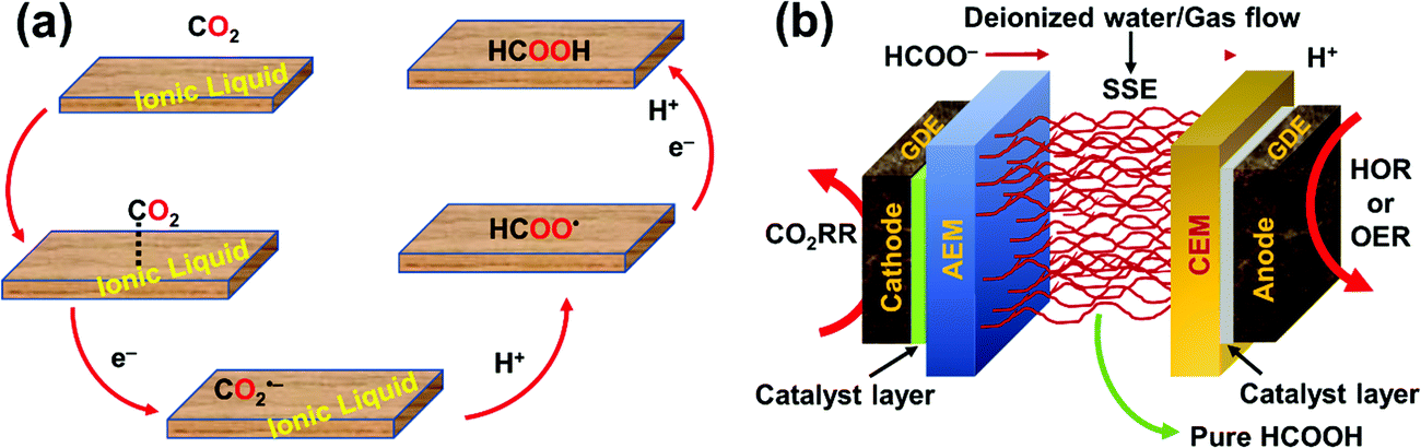 | ||
| Fig. 34 (a) Possible reaction mechanism for the eCO2RR towards FA formation in IL containing catholytes on the electrode surface.184 (b) Schematic illustration of an all solid-state reactor containing solid electrolyte for the eCO2RR to pure FA.185,186 | ||
Since the eCO2RR is often carried out in aqueous solution to facilitate ion conduction between electrodes, it is inconvenient and energy-intensive to separate a liquid product like FA from dissolved salts. To overcome this difficulty, very recently, Wang and co-workers sought to employ a porous solid-state electrolyte (PSE/SSE) in an eCO2RR cell to produce neat FA (Fig. 34b).185 The implementation of a novel PSE idea was inspired by battery chemistry where ions are shuttled between electrodes via ion-conducting solid polymers. The continuous production of pure FA solutions up to 12 M was successfully demonstrated with negligible degradation and high selectivity using the 2D-Bi//SSE-50//IrO2-C cell with an average domain size of SSE of 50 μm. Furthermore, insoluble inorganic proton conductors, such as CsxH3−xPW12O40, were also employed for pure FA generation, significantly expanding the application range. As the solid electrolyte is insoluble, those FA molecules can be collected in a deionized water flow, which makes the product concentration limited in the PSE layer, impeding its practical applications. Due to the presence of a significant amount of water, the product generation rate was not sufficiently high for industrial applications. It also involved the use of liquid electrolyte on the anode side for water oxidation. With further advancement in the field of PSE, an all-solid-state eCO2RR system was introduced for continuous generation of high-purity and high-concentration FA vapors and solutions which can be efficiently removed in the form of vapors via inert N2 gas flowing through the PSE layer.186 As a result, concentrated FA could be achieved without sacrificing much selectivity compared with the deionized water flow design. Coupling with a high activity (jFA ∼450 mA cm−2), selectivity (FEmax ∼97%) and stability (100 h) grain boundary-enriched Bi catalyst, ultra-high concentrations of pure FA solutions (up to ∼100 wt%) were achieved, condensed from generated vapors via flexible tuning of the carrier gas stream through PSE. This new set-up distinctly represents a superior catalytic performance compared with the existing systems.
3.2. Effects of pH and pressure
The selectivity as well as the reaction rate of the eCO2RR system can be directly influenced by the pH to avoid the inhibition of the undesired and competitive HER, which is more pronounced in acidic media. 0.1–0.5 M NaHCO3 or KHCO3 was found to be a suitable choice for the aqueous eCO2RR because HCO3− ions can serve as a buffer to maintain the pH within 7.25 ± 0.05 although the local pH near the electrode surface may vary.202 For sp group metal cathodes, e.g. Hg, In, Sn and Pb, the production of FA is more favored in neutral solution, and formate is produced exclusively in weak alkaline solution.203 In this context, the relationship between the pH values and potentials of CO2 as well as other related substances was established by Hori in a Pourbaix diagram (Fig. 35a).204 It has been disseminated that in order to obtain formate or FA, medium potentials are required and an acidic environment is advisable regarding CD, selectivity and η. Bumroongsakulsawat and co-workers have shown that by increasing the pH of the aqueous solution from 2.9 to 7.8, the molar ratio of CO:formate decreased from 1 to 0.15 during the eCO2RR at Sn electrodes.205 Vlugt and co-workers have recently reported a high-pressure semi-continuous batch electrolyzer with a Sn-based cathode to convert CO2 to FA at low pH conditions.206 Although the FE of FA in alkaline media was higher by 10%, it produced formate that required downstream separation. As FA (with concentration >85% of FA) is a more attractive chemical compared to formate from an economic perspective, the development of a better electrolyzer that can operate at low pH is needed (without sacrificing the product selectivity and final product concentration after downstream separation).
 | ||
| Fig. 35 (a) Potential versus pH value of CO2 and related substances.204 (b) High pressure reactor for CO2 electroreduction.207 | ||
Apart from solution pH, the influence of elevated pressure in the electrochemical reactor has also been evaluated. Hara et al. investigated the eCO2RR activity at a pressure of 30 atm on various electrodes at large j (163–700 mA cm−2) in an aq. KHCO3 solution using a high pressure glass cell reactor enclosed in a stainless steel autoclave (Fig. 35b).207 While j for FA and/or CO production increased with increasing CO2 pressure from 1 atm to 30 atm on Ag, Au, Zn, Pb and In metals, on group 8–10 metals, the total j changed only slightly upon increasing the CO2 pressure. Interestingly, a decrease of the CO2 pressure to 1 atm resulted in the formation of H2 for group 8–10 metals, indicating the vital role of the cell pressure during the eCO2RR. Very recently, Proietto et al. employed an undivided filter-press cell with continuous recirculation of the electrolytic solution at a Sn cathode to convert CO2 to FA/formate under high CO2 pressures.208 FEFA and the final product concentrations were significantly improved from 15% and 2.0 mM to 39% and 5.8 mM to 64% and 9.6 M by increasing the CO2 pressure from 1 to 5 bar to 15 bar, respectively. However, a further increase in the pressure did not show any significant improvement. Finally, this new system was found to be stable with time and could generate FA of a final concentration up to 0.4 M at an elevated pressure (23 bar) and CD (∼50 mA cm−2). The impact of the CO2 pressure on j for CO2-to-FA/formate conversion was studied by Morrison and co-workers. At pressures above 10–20 bar, the FE of ∼95% and the specific energy of formation of 3.7 kW h kg−1 were found to be the highest.209 The Vlugt group has also designed a unique CO2 electrolyzer for CO2 electrolysis to FA/formate at high pressure (up to 50 bar) using bipolar membranes (BPMs).210 It was observed that the concentration of formate, the FE and CD sharply increased as the CO2 pressure increased. The FE showed a maximum of ∼90% under 40 bar CO2 with a slight decrease thereafter, likely due to formate crossover through the membrane and a pH drop caused by CO2 dissolution. More recently, Dai et al. employed Cu2O nanoparticle (NP) films as cathode materials for the eCO2RR to HCO2− under ≥45 atm CO2 in bicarbonate catholytes to reach an FE of ∼98% at −0.64 V vs. RHE.211 More importantly, when this cathode was paired with a newly developed NiFe hydroxide carbonate anode in KOH/H3BO3 anolyte, the resulting high-pressure cell could achieve an energy conversion efficiency of up to 55.8% for long-term formate production. Relevant studies and experimental results related to FA/formate formation (FE and j), aided by an elevation in partial CO2 pressure, have been summarized in Table 9.164
| Pressure [atm] | Electrode material | Observations | Ref. |
|---|---|---|---|
| a Non-selective formation of FA/formate has also been considered in this table. b FA forms along with other hydrocarbons, CO and H2. | |||
| 1–5 | Sn | FEFA increases from 15% (1 atm) to 39% (5 atm) at a CD of 20 mA cm−2 | 208 |
| 5–15 | FEFA increases 39% (5 atm) to 64% (15 atm) at a CD of 20 mA cm−2 | ||
| 10 | Cu | FEFA reaches 15%b at −3.0 V (vs. Ag quasi-reference electrode) | 212 |
| 20 | Cu | FEFA reaches 27.8%b at −1.27 V (vs. Ag/AgCl) | 213 |
| Hg | FEFA reaches 100% at a PCD of 201.8 mA cm−2 | ||
| 30 | Pb, In | FEFA reaches 96.3% and 90.1% at a PCD of 192.6 and 180.2 mA cm−2, respectively | 213 |
| 40–50 | Sn | FEFA reaches ∼90% at a cell potential of 3.5 V and CD of ∼30 mA cm−2 | 210 |
| 45 | Cu2O/Cu | FEFA reaches 97.7% at a PCD of 5.2 mA cm−2 | 211 |
| 60 | FEFA reaches 98.2% at a PCD of 5.7 mA cm−2 | ||
| 60 | In, Sn, Pb | FEFA reaches ∼100% for In at 20–60 °C; 99.2% for Sn at 20 °C; and 91.2% for Pb at 60 °C | 214 |
3.3. Electrode materials
Traditional electrodes are metals that play a dual role as the support and catalyst. For example, Pd, In, Bi and Sn are active for FA production.215–217 However, the poor product selectivity and durability limit their practical application. With extensive inspection of eCO2RR mechanisms, it emerges that electrocatalytic CO2 reduction is highly governed by the electronic structure of the electrode materials, morphological and interfacial properties, and reaction conditions. Other than the expensive and less abundant pure metal electrodes, an electrode is commonly comprised of a cheap substrate and a catalyst layer (CL) which usually provides active catalytic sites by adhering the catalysts on its surface and facilitates electron transport with low resistance. GDEs are now often utilized in the modern fuel cell design. Highly conductive carbon black (CB) is usually used to support catalyst particles as a conventional CL, and highly porous carbon paper (CP) or carbon cloth is employed as the gas diffusion layer (GDL) (Fig. 36).218 GDEs are found to be more advantageous due to: (1) enhanced passage and transport of gaseous CO2 towards the active site (through the substrate and CL) and removal of gaseous by-products preventing cathode flooding, (2) easy release of the liquid product like FA into the electrolyte, (3) providing mechanical support and protection from corrosion or erosion, (4) acting as a medium for heat transfer, and (5) avoiding the mass transport limit that prevails in liquid-phase systems due to low solubility of CO2. Liquid-phase reactors have thus been transformed to gas-phase systems in recent years to make the eCO2RR more feasible for practical applications. Gaseous CO2 can be supplied directly, circumventing the major challenges associated with conventional electrodes for providing an incentive for the development of an advanced industrial process (Fig. 36). GDEs manifest a high electroactive surface for working at higher current densities than those used with conventional plate electrodes. GDEs enhance the three-phase boundary area, ultimately increasing the FE, CD and concentration of FA/formate produced. | ||
| Fig. 36 Schematic representations comparing the concept of the (a) liquid-phase and (b) gas-phase CO2RR occurring in conventional and GDEs, respectively.218 | ||
Utilizing the advantages of GDEs, Furuya et al. have examined the performance of Ru, Pd and a Ru–Pd alloy (1:1) on GDEs for the eCO2RR in 0.5 M KHCO3 aqueous solution.203 The reactivity of the Ru–-Pd GDE was the highest among the others, offering high FA selectivity without CO formation and a current efficiency of 90% at −1.1 V vs. NHE (j = 80 mA cm−2). Lee et al. fabricated a compact zero-gap electrolytic cell for a direct eCO2RR to FA utilizing a Sn nanostructure catalyst layered onto carbon diffusion paper with 30 wt% Nafion to prepare a GDE.219 This catalytic system showed an initial FEFA of ∼12.5% at −0.7 v vs. RHE. While FEFA decreased to 7% after 3 h of electrolysis, it remained above 5% for over 10 h of electrolysis. Recent reports that have applied this strategy with Sn catalysts for CO2-to-formate conversion are summarized in Table 10.
| Catalyst layer | Carbon support | FE (%) | PCD (mA cm−2) | Applied potentiala | Ref. |
|---|---|---|---|---|---|
| a Applied potential values are taken as reported in the literature and not adjusted. b PTFE = polytetrafluoroethylene. | |||||
| Sn-loaded Cu mesh | CB | 78.6 ± 0.11 | 17.43 ± 2.60 | −1.8 V (vs. Ag/AgCl) | 220 |
| Reduced Sn particles | PTFEb | 72.99 ± 1.91 | 13.45 ± 0.72 | −1.8 V (vs. Ag/AgCl) | 221 |
| Sn nanopowder | Acetylene black + graphite + PTFEb | ∼90 | 200 | −1.57 V (vs. SHE) | 222 |
| Sn powder (150 nm) | CP | 68.8 | 90 | −2 V (vs. Ag/AgCl) | 223 |
| SnO2 microspheres | CP | 62 | 12.5 | −1.7 V (vs. SHE) | 224 |
| Sn NPs | Vulcan XC72R | 70 | 150 | −1.5 V (vs. Ag/AgCl) | 225 |
| SnO2 | Vulcan XC72R | 80 | 251 | −1.43 V (vs. RHE) | 226 |
A 2D-metal derived catalyst, BiOBr, was reported by Sargent and co-workers for formate production.227 The BiOBr-templated catalyst was prepared by coating BiOBr in DMSO solution onto CP followed by annealing in an inert atmosphere. The eCO2RR activity of the BiOBr-templated catalysts was tested in an aqueous H-cell set-up which reached CO2 mass-transport limitations, having a CD of ∼80 mA cm−2 and an FE of 99% (at −1 V vs. RHE). The PCD increases significantly (ca. 2.5 times) without compromising the formate selectivity when BiOBr was subsequently deposited on top of a GDE (vide infra).
The Huang group has demonstrated an optimized annealed Cu foam electrode with a high electroactive surface area and lower η for the eCO2RR, taking advantage of the good conductivity and high specific surface area of the Cu-electrode.228 While good selectivity towards the eCO2RR was observed, the formate selectivity was low with an FEFA of ∼23% at −0.45 V vs. RHE. Wang et al. deposited Sn on a Cu foam substrate (Sn/f-Cu) by electrodeposition in an aqueous plating solution in an effort to combine the strength of both metals through synergistic effects. Indeed, the resulting Sn/f-Cu electrode exhibited excellent and superior catalytic activity compared to the individual Cu foam and Sn plate with an FE reaching a maximum value of 83.5% at −1.8 V vs. Ag/AgCl and PCD = 8 mA cm−2.229 The Guan group prepared Bi-doped SnO nanosheets on Cu foam (Bi–SnO/f-Cu) by a one-step hydrothermal reaction as a cathode material for the eCO2RR to FA.230 This material was found to be a better electrocatalyst than Sn/f-Cu with an FE of 93% at −1.7 V vs. Ag/AgCl, a PCD of 12 mA cm−2, and good stability for 30 h of operation. Comprehensive studies revealed the role of Bi doping in stabilizing the Sn2+ on the surface against being reduced to Sn0 during the electrochemical reduction process. Furthermore, DFT calculations supported the fact that, while Bi doping escalated the adsorption ability of the SnO(001) facet for OOCH* intermediates, the additional inclusion of Cu foam on Bi–SnO helped maintain Sn in a+ve oxidation state, and favored the adsorption of *OOCH intermediates, thereby increasing the selectivity towards FA appreciably. To overcome the difficulties from the requirement of relatively high η and j (to reach a high FE) for metallic Bi, the Zhang group has designed lattice-dislocated Bi nanowires (NWs) on Cu foam (BiNW/f-Cu) through an in situ electrochemical transformation.231 BiNW/f-Cu was proved to be an active electrocatalyst for CO2-to-formate conversion with an FE of 95% at low η and PCD of ∼15 mA cm−2 at −0.69 V vs. RHE. The great catalytic performance of the BiNW/f-Cu cathode may originate from the presence of crystal lattice dislocations and the large catalytic surface area of the porous structure of the electrode. These observations open the direction for the use of crystal defect engineering to improve the efficiency for large scale electroreduction but this is currently beyond the discussion of this review.232
3.4. Catalysts
Exclusive electrochemical conversion of CO2-to-FA/formate is only achievable with highly selective catalysts that can lower the overpotential and suppress the competing HER process. The product distribution and conversion efficiency during the eCO2RR largely depend on the cathodic catalysts. In order to obtain the best performance and maximum efficiency during electrocatalysis, it would be the ideal case if an electrocatalyst can produce a single targeted product with 100% FE at a low η with a large CD and long-term stability. The electronic structure along with a tri-phasic interface and the local morphology of the cathodic materials/catalysts have important roles to play in controlling the activity, selectivity, and durability of the catalytic system (Fig. 37).232 But it has been recognized that optimizing the activity and stability without compromising the selectivity of the electrocatalysts is one of the biggest challenges to be addressed before practical implementation can be realized. Importantly, the catalysts should be economical for large-scale industrial applications. In this section, the development of catalysts will be summarized in four categories. | ||
| Fig. 37 Representations of the basic requirements for an ideal CO2RR catalyst.232 | ||
| Electrode | Potential (vs. NHE) | PCD (mA cm−2) | FE (%) | Electrolyte |
|---|---|---|---|---|
| a The authors report an exceedingly high FE towards formate in acidic media, which is rare. b An additive CTAB has been added to the electrolyte with an unmodified Cu electrode. | ||||
| Pb | −1.63 | 5.0 | 97.4 | 0.1 M KHCO3 |
| Pba | −2.76 | 115 | 97.0 | 0.35 M Na2SO4 (pH 2.0) |
| Pb | −1.59 | 2.5 | 90 | 0.5 M NaOH |
| Hg | −1.51 | 0.5 | 99.5 | 0.1 M KHCO3 |
| In | −1.55 | 5.0 | 94.9 | 0.1 M KHCO3 |
| Sn | −1.48 | 5.0 | 88.4 | 0.1 M KHCO3 |
| Sn | −1.60 | 27 | 70 | 0.5 M NaHCO3 |
| Cd | −1.63 | 5.0 | 78.4 | 0.1 M KHCO3 |
| Tl | −1.60 | 5.0 | 95.1 | 0.1 M KHCO3 |
| Cub | −0.92 | 2.5 | 82.3 | 0.5 M KHCO3 |
While Pd is a very promising and commonly used d-group metal reaching high FEs at high j,238 Rh and Ir produce mainly H2 and CO with poor selectivity towards FA.207 Surprisingly, bulk Pd is not an efficient CO2RR electrocatalyst for FA production, but Pd NPs, either dispersed on carbon or embedded in conductive polymers, exhibit high efficiency and selectivity at low overpotentials but also at low j. The Wrighton group reported that a Pd-impregnated polymer on a semiconductor or metallic electrode produced formate from HCO3− and H2 with up to 85% FE and a maximum PCD of 100 μA cm−2 at −0.8 V (vs. SCE).239 Similarly, an electrochemically deposited Pd on Pt electrode produced formate with an FE close to 100% near thermodynamic potentials between pH 8–10 but with a low PCD.238 An increase in the PCD was attempted by applying η but resulted in an exclusive HER, presumably due to the faster protonation of the adsorbed H atoms. Employing dispersed Pd NPs on a carbon support, Min and Kanan were able to achieve high reaction rates, reaching an average FE of 95% with the geometric CD as high as 10 mA cm−2 at −0.2 V vs. RHE towards formate production (Fig. 38a).240 Electrokinetic measurements are consistent with a mechanism where the rate-determining step is the addition of electrochemically generated surface adsorbed hydrogen to CO2 (i.e., electrohydrogenation). The Pd electrodes deactivate over the course of several hours because of CO formation in a minor pathway. However, the activity is recovered by removing CO with brief air exposure (Fig. 38a). Thereafter, three different sizes of Pd NPs ranging from 3.8–10.7 nm capped with polyninylpyrrolidone (PVP) were prepared by Broekmann and co-workers to provide insights on the size-dependent activity at low η.241 The FE of 98% for Pd NPs (6.5 nm) was found to be the highest, followed by an FE of 86% for Pd NPs (3.8 nm) at −0.1 V vs RHE. The FE then dropped when the size of the NPs became larger. The superior efficiency towards formate production at low overpotentials for both examples was rationalized in terms of a changed catalytic pathway through a hydrogenated Pd phase (β-PdH) in situ generated electrochemically close to 0 V vs. RHE and not pure Pd as observed in bulk Pd. Later, the Sargent group designed Pd nanoneedles for the eCO2RR to formate and obtained an FE > 90% with an unprecedented geometric CD of 10 mA cm−2 during controlled potential electrolysis (CPE) at −0.2 V (vs. RHE) over 20 h.242 The performance and reactivity of this Pd material surpassed those of Pd nanorods, Pd particles and other previously reported Pd needles. In this study, high electric fields have been applied locally to increase the local CO2 concentration close to the active surface. These results were supported by simulations that revealed ten-fold higher electric fields associated with metallic nanometer-sized tips compared to quasi-planar electrodes, as observed in the case of electrocatalytic CO2-to-CO conversion as well.243
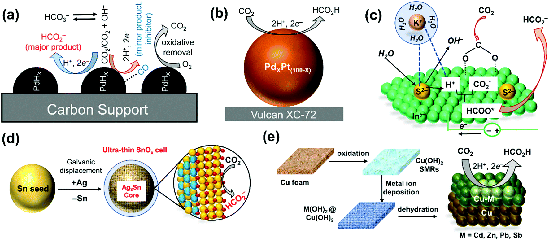 | ||
| Fig. 38 Schematic representations towards formate production during the eCO2RR by (a) PdHx species on the Pd/C surface via the electro-hydrogenation mechanism240 and (b) PdxPt(100−x) on a carbon support247 in aqueous buffer. (c) Schematic illustration of the role of S2− in promoting water dissociation and H* formation for the reduction of CO2 to formate by S-doped In surfaces.248 (d) Synthesis of an ultrathin partially oxidized tin oxide catalyst with an Ag–Sn core for the eCO2RR towards formate production.249 (e) Graphic illustration of the synthetic procedure of Cu–M (M = Cd, Zn, Pb, Sb) alloys from their hydroxide precursors on a Cu-foam electrode and electrocatalytic FA production.250 | ||
Realizing the advantages of using nanostructured materials over bulk materials because of their enhanced surface area arising from more surface-active sites and sharpness, Bi, located close to traditional formate-producing metals in the periodic table, has been recently considered as a promising electrocatalyst. Based on these ideas, Kim et al. designed an electrode of Bi nanoflakes on a Cu film by a pulse current electrodeposition method to facilitate selective CO2 reduction to formate with an FE of 79.5% at −0.4 V vs. RHE for over 10 h of stability. This FE could be maximized to 100% at −0.6 V vs. RHE.244 Later, the Li group reported an ultrathin Bi nanosheet (NS), derived from BiOI, to be a high-performance cathodic material for the eCO2RR to formate with an FE >90%, a PCD of 24 mA cm−2 at −1.74 V vs. SCE, and durability for >10 h.217 The high performance of the Bi NS can be attributed to the enlarged surface area and abundant under-coordinated Bi sites. To gain further insights into the outstanding eCO2RR performance, DFT calculations were carried out using the computational hydrogen electrode methodology. The energy profiles suggest that CO2 reduction is initiated with a PCET step, leading to the protonation of a C or O atom. It was found that, while the protonation of the C atom to form the OCHO* intermediate was mildly endothermic (+0.49 eV), the 2nd PCET was exothermic (−0.17 eV), and it finally transformed to HCOO− and spontaneously releases from the catalytic surface as formate. In contrast, not only was the protonation of the O atom in CO2 to COOH*, an intermediate to CO, significantly uphill in energy (+1.16 eV), but also the free energy of H adsorption on Bi(001) was similarly too positive (+0.95 eV) to allow an active HER. Thus, DFT calculations suggested that the high reaction selectivity is a result of its stabilized intermediate (OCHO*) on Bi(001) relative to COOH* or H*. The same group continued to fabricate a mesoporous Bi NS from Bi2O2CO3 which was also very selective and stable with an FE of ∼100%, a PCD of 18 mA cm−2 at −1.1 V vs. RHE, and stability >12 h during the course of the eCO2RR to formate.245 Interestingly, when these Bi and mesoporous Bi NS catalysts were coupled with an oxygen evolving Ir/C catalyst to achieve full-cell electrolysis, it exhibited an impressive FE and electricity-to-formate conversion efficiency. Wu et al. prepared a phase-pure 2D Bi NS with a few layers from bulk solid crystals by rapid electrochemical cathodic exfoliation.246 A cost-effective and commonly used industrial Bi ingot chunk was employed, making the catalyst preparation a greener, accessible, and up-scalable method. This cathode material maintained an FE over 80% for CO2-to-formate conversion from −0.77 to −1.17 V vs. RHE, likely due to the remarkably enhanced adsorption ability of CO2 and the corresponding intermediates. This Bi NS also displayed long-term stability for 17 h without any significant decay, stabilizing the total CD at 25 mA cm−2 at −0.97 V vs. RHE. These reports strongly suggest that judicious tailoring of the nanostructure plays a key role in developing a high performance noble-metal-free catalyst for the eCO2RR in aqueous solution.
Besides single metal materials, the use of alloys is often found to be very effective in enhancing both the activity and selectivity for the eCO2RR to FA. A significant amount of evidence supports that the combination of different types of metals can favorably control the surface chemical environment and relative binding energy with different intermediates, ultimately producing products that could not be achieved by either metal alone. Koper and co-workers prepared a Pd/Pt alloy by electrodeposition of Pd on Pt to reduce CO2 to FA starting from −0.5 V vs. RHE at pH 6.7. This onset potential was significantly lower than −1.2 V vs. RHE for a bare Pd electrode under the same conditions.251 Unfortunately, the formation of CO on the surface rapidly poisoned the catalyst with slow deactivation, resulting in diminished catalytic activity. Later on, the synthesis of PdxPt(100−x)/C NPs was also reported, which can reduce CO2 to FA at an even lower onset potential of 0 V vs. RHE (Fig. 38b).247 After screening the ratios of Pd to Pt to further evaluate the effects of Pd and/or Pt in PdPt/C during catalysis, Pd70Pt30/C was found to be the best among the others towards FA production with CDavg = ∼5 mA cm−2 and an FE of 88% at −0.4 V vs. RHE. Therefore, after hybridization of Pd and Pt at a certain ratio, the CO poisoning rate could be reduced drastically without signficantly affecting the kinetic parameters. It was hypothesized that, while fine-tuning of the d-band center by mixing Pt and Pd was important for enhancing the activity, lattice strain effects in the NPs induced by bigger Pt atoms were also beneficial.
The Sargent group introduced a sulfur-modulated Sn (Sn(S)) catalyst on an Au electrode by atomic layer deposition of SnSx and subsequent reduction.252 This modified Sn(S)/Au electrode enhanced formate generation with an FE of 93% at a geometric CD of 55 mA cm−2 at −0.75 V vs. RHE for over 40 h without deactivation, outperforming Sn NP/Au with an FE of 30.2% at a CD of 42 mA cm−2 at the same potential. This improvement in activity may come from the undercoordinated Sn sites due to the incorporation of S-atoms. Similarly, Wang and co-workers discovered a unique S-doped In catalyst, obtained by electroreduction of S-containing In2O3 precursors which grew on carbon fibers, for the eCO2RR to formate with high selectivity (FE > 85%) at a high CD (25–100 mA cm−2) in aqueous alkaline media.248 When KHCO3 was replaced with CsHCO3, the formation rate of formate increased to a record high 1449 μmol h−1 cm−2 from 1002 μmol h−1 cm−2 with a CD of 84 mA cm−2 and an FE of 93%, arguably the highest formation rate of formate reported to date for the eCO2RR. In this study, unique surface adsorbed sulfur boosting water activation was revealed where S−2 was proposed to interact with the hydrated K+/Cs+ in the double layer, contributing to the dissociation of H2O to form adsorbed H* species. This H* could form the HCOO* intermediate, the precursor for formate (Fig. 38c).
The Jiao group synthesized an Ag–Sn/SnOx core–shell nanostructure by initiating the formation of Sn seeds in the presence of PVP, followed by galvanic displacement of Sn with Ag (Fig. 38d).249 The SnOx shell thickness of 1.7 nm was identified to offer the best selectivity and activity with an FE of ∼80% and a PCD of ∼16 mA cm−2 at −0.8 V vs. RHE. CO2 activation and conversion were promoted by the high electronic conductivity and oxygen vacancies in the bimetallic Ag–Sn core. Similar to the work of Jiao, Cuenya and co-workers also reported the efficacy of the SnOx layer by fabricating SnOx/AgOx electrocatalysts through electrodepositing Sn on O2-plasma-treated Ag surfaces.253 While SnOx/AgOx displayed an enhanced CD and C1 product (CO/FA) selectivity (≥95% at −0.8 V vs. RHE) suppressing the HER below 5% after 20 h, for Sn-free AgOx the HER selectivity was increased by ∼40%. It was proposed that the Sn electrodeposition may form stable Snδ+/Sn species on the rough AgOx surface and preserve the surface roughness under the reaction conditions better than that of the uncoated AgOx surface. Bai et al. took advantage of a modified wetting chemistry reduction method to prepare activated carbon supported Pd–Sn alloy PdxSn/C and the catalyst exhibited a nearly 100% FE at the lowest overpotential of 0.26 V, outperforming the above-mentioned Ag–Sn core–shell bimetallic catalyst.254 The largest amount of PdOx species was formed on the surface of the catalyst by virtue of tuning the electronic state, resulting in superior performance for CO2-to-formate conversion. While an improved FEformate has been observed with binary Sn-based catalysts containing Au, Ag, Pd etc., their use for large-scale CO2 reduction systems may be limited because of the comparatively expensive materials used.
To make CO2-to-FA conversion more economic and practical, researchers were motivated to replace more expensive and low abundance metal catalysts. Wen et al. have designed and synthesized a bimetallic Bi–Sn catalyst with unique morphology control that converted CO2-to-formate with a remarkably high FE of 96% and a production rate of 0.74 mmol h−1 cm−2 at −1.14 V vs. RHE. The catalyst stability was maintained for over 100 h in continuous operation.245 This excellent performance can be attributed to the sub-atomic orbital interactions between Bi NPs and the underlying Sn NS, resulting in p and d orbitals of Sn electronic states being upshifted away from the Fermi level for the electron density to shift from Sn to the more electronegative Bi. These orbital interactions can also stabilize the HCOO* intermediate, thus boosting the selectivity of formate over CO and H2. Moreover, the Bi–Sn NS structure was found to be very robust with enhanced edge site exposure and could promote mass transport of CO2 and formate during the reactions. Cui and co-workers investigated the thermochemical reaction energetics of the CO2RR and the competing HER on Sn, CuSn, CuSn3 and Cu using DFT calculations.255 The corresponding free energy diagrams (FEDs) for these systems are presented in Fig. 39. In the case of CO and H2 production, COOH* and H* are the relevant intermediates, respectively. On the other hand, while the formation of COOH* has been suggested to be the potential limiting step on Cu and Sn for formate production, it is suggested to be OCHO* on CuSn and CuSn3. Both CuSn and CuSn3 show higher thermodynamic limiting potential values than Cu and Sn, suggesting that the alloying of Cu with Sn significantly enhances the formate selectivity, with CuSn3 having the lowest activity towards both CO and H2. In addition, the structures of the alloys are markedly different from those of both Cu and Sn. Hence, it was concluded that the improved selectivity of CuSn and CuSn3 alloys originates from a combination of geometric and electronic effects. Finally, this theory-guided discovery predicted CuxSny to be active electrocatalysts, among which the CuSn3 variant is suggested to be the most promising candidate, which catalyzes the eCO2RR to formate with a high selectivity of 95% at −0.5 V vs. RHE and excellent stability for over 50 h. It was observed that the incorporation of Cu into Sn facilitated the transfer of electrons from Sn to Cu, making Sn stay in the 0 and +2 oxidation state under the operating conditions for formate generation. On the same front, Ye et al. reconstructed a Sn2.7Cu catalyst and achieved a CD as high as 406.7 mA cm−2 with an FE of 98.0% at −0.70 V vs. RHE, and stability at 243.1 mA cm−2 with an FE of 99.0% over 40 h of electrolysis at −0.55 V vs. RHE.256 The in situ reconstructed Sn/SnOx interface may promote formate production by optimizing the binding of the reaction intermediate HCOO* to suppress the HER.
 | ||
| Fig. 39 FEDs for CO, HCOOH and H2 production on Sn, CuSn, CuSn3 and Cu, respectively.255 | ||
It is well-known that alloying Cu with other metals provides a useful strategy to alter the product selectivity. Mosali et al. deposited M-hydroxides (M = Cd, Sb, Pb, Zn) onto Cu(OH)2 sub-micron-sized rods (SMRs), grown on Cu foam, followed by dehydration and electrochemical reduction to form MCu on the Cu SMR surface (Fig. 38e).250 Under bulk electrolysis (BE) conditions in the presence of CO2, CdCu@Cu exhibited the highest selectivity towards formate production with an FE of 70.5% and a PCD of 30.5 mA cm−2, while ZnCu@Cu and PbCu@Cu only showed moderate selectivity with SbCu@Cu being the least. Irrespective of the composition, all alloyed structures were stable over 12 h of BE experiments.
Among various laboratory-scale metal-oxide catalysts for catalytic CO2-to-FA conversion, Sn-oxides have attracted considerable attention because their structures and chemical compositions could be strategically modified to achieve desirable catalytic performance for formate/FA formation.176 The Chen group employed a thin-film catalyst by simultaneous electrodeposition of Sn0 and SnOx on a Ti electrode and achieved an up to 8-fold higher PCD and 3-fold higher FE for CO2 conversion to FA than those of the Sn foil counterparts.257 Meyer and co-workers used SnO2 nanocrystals with a high surface area to carry out the eCO2RR to formate at η as low as ∼340 mV in aqueous NaHCO3 solution.258 The size of the SnO2 NPs could significantly influence the FE and CD. When the CB support was replaced by graphene with a higher surface area, an FE of >93% and a CD of 10.2 mA cm−2 at −1.8 V vs. SCE were achieved with good stability for 18 h. Won and co-workers investigated how the native O-content can be used as a selectivity descriptor in the eCO2RR and hence a hierarchical Sn dendrite electrode (SnOx/Sn) was synthesized with high O-content, consisting of a multi-branched conifer-like structure with an enlarged surface area.259 The reduced Sn electrode with abundant O-species, which survived under highly reductive conditions, effectively stabilizes a CO2˙− intermediate rather than a bare Sn surface and exhibited a superior formate production rate of 228.6 μmol h−1 cm−2 at −1.36 V vs. RHE without any considerable catalytic degradation over 18 h of operation. Finally, in order to explain the importance of oxide layers on top of the Sn electrode, Zhang et al. deliberately removed the oxide layer via etching followed by exposing the etched Sn electrode to the air over 24 h as a control.260 The electrochemical results indicated that, while the Sn electrode with a native oxide layer exhibited a higher CO2 reduction activity towards formate (FE ∼84% and CD ∼3.8 mA cm−2), the activity decreased for the etched Sn electrode (FE ∼43% and CD ∼5.2 mA cm−2). Meanwhile, it has been observed that the catalytic performance of the SnOx electrode was restored with an enhancement of 1.5-fold in the CD (FE ∼85% and CD ∼5.5 mA cm−2) when exposed to air compared to that for an untreated Sn electrode because the etching treatment made the electrode surface rough, thus creating a larger active surface area. To further justify the role of metal oxides in improving the performance of the eCO2RR for practical applications, Broekmann and co-workers utilized potential and time-dependent operando Raman spectroscopy to monitor the structural change involving reduction of a SnO2 NP catalyst to metallic tin.261 This reduction, in fact, resulted in a decreased FE for the production of formate at cathodic potentials where SnIV was reduced to metallic Sn0. Subsequently, to obtain detailed mechanistic insight into the electrochemical reduction of CO2 on Sn electrodes in real time, Baruch et al. employed in situ attenuated total reflectance infrared (ATR-IR) spectroscopy.262 The working electrode was a Sn film deposited onto a ZnSe crystal using ion beam sputtering and the crystal was mounted into a custom-made three-electrode cell. Using the IR spectro-electrochemical (IR-SEC) technique, 2e− reduction of the electrode from a native SnO2 NP layer to a meta-stable SnII-oxyhydroxide (Sn6O4(OH)4) species occurred under electrolysis conditions. The IR-SEC data indicated that this species then reacted with CO2 to form a surface-bound carbonate, followed by transfer of 2e−/1H+ to form formate, which was then released from the surface to regenerate the SnII-oxyhydroxide (Fig. 40).
 | ||
| Fig. 40 Proposed mechanism for the electrochemical reduction of CO2 to formate on Sn/SnOx cathodes along with an in situ ATR-IR study on the cathode film deposited on a ZnSe ATR crystal via the IR-SEC technique.262 | ||
From the discussions thus far, the potential of SnOx materials is clear for the selective production of FA. Metals in the liquid state can form a thin oxide layer when exposed to air. Although room temperature fabrication of 2D metal-oxides through gas-injection and water dispersion has been demonstrated, analogous processes in non-aqueous solvents at elevated temperatures remain challenging. The Hu group reported the mass-production of free-standing amorphous 2D SnOx nanoflakes with Bi decoration from a liquid Sn–Bi alloy by controlled exposure to oxygen in well-selected hydroxyl-rich non-aqueous solvents.263 The resulting 2D SnOx offered a high FE of >99% for the eCO2RR to FA and stable performance over 10 h. This work demonstrated how a liquid metal can form a thin layer of oxide skin via exposure to oxygen and the hydroxyl-rich solvents exhibit the best morphology control toward 2D SnOx through strong and stabilizing solvent–oxide interactions with the liquid metal-oxide surface of the nanoflakes. After the success of hierarchical 2D SnOx electrodes with high surface area for selective formation of formate with high performance, Li et al. extended this idea to synthesize 3D hierarchical mesoporous SnO2 NSs on carbon cloth (CC) to efficiently carry out CO2-to-FA conversion in aqueous media.264 The electrode, fabricated by a facile combination of hydrothermal reaction and calcination, exhibited an unprecedented PCD of ∼45 mA cm−2 at η close to 880 mV with an FE of 87% and long-term stability. This superior performance may be attributed to the robust and highly porous hierarchical structures, providing a large surface area to facilitate charge and mass transfer.
While the influence of oxide layers and/or the oxide content on Sn electrodes has been discussed thoroughly in ameliorating the performance as well as selectivity of formate production during the eCO2RR, other metals and/or their corresponding oxides remain relatively unexplored. To elucidate the roles of non-Sn metals and metal-oxides, Xie et al. fabricated two different Co materials of 4-atom-thick layers; one consisting of pure Co and the other with the co-existence of Co and CoO.265 The surface Co atoms of the atomically thin layers were found to be more reactive than those on the bulk samples for formate production by the eCO2RR at low η. Thus, the exceptional increase of the intrinsic activity by 10 times was observed by the partial oxidation of the atomic layers with a CD of 10.59 mA cm−2 over 40 h and 90.1% formate selectivity at η = 240 mV. These results strongly suggested the importance of the morphology and oxidation state(s) to the catalytic activities. Liu and co-workers recently reported the preparation of and eCO2RR to FA using an In-oxide based catalyst (In2O3@C) which was grown on CB by a two-step process of coprecipitation and pyrolysis.266 In2O3@C achieved a maximum FE of 87.6% at −0.9 V vs. RHE in aqueous electrolyte and was stable for up to 12 h, outperforming most In-based electrocatalysts.
A new sub-class of metal/metal-oxide based catalysts, termed as oxide-derived (OD) materials, has recently emerged with enhanced activity and selectivity compared to those of the parent bulk materials or NPs, presumably because of the formation of a greater number of highly active grain boundaries. These OD-materials were generally obtained after formation of thick oxide layers, formed through electrochemical oxidation.235 When OD-Bi films were prepared on Ti substrates via electrochemical and thermal oxidation from metallic Bi films by the Bertin group, a significantly higher geometric CD could be observed for OD-Bi (j = 8.3 mA cm−2) than that of Bi metal (j = 1.6 mA cm−2) only at a 100 mV larger η, although the FEs for both films were almost identical.267 Lee et al. later identified carbon supported BiOx (BiOx/C) as a promising and environmentally benign and more economic catalyst for the eCO2RR to formate with an average FE of 93.4% at potentials from −1.37 to −1.70 V (vs. Ag/AgCl). A PCD of 16.1 mA cm−2 at −1.75 V vs. Ag/AgCl could be achieved with a formate production rate of 300 μmol cm−2 h−1.268 Notably, this was the first report where dual mechanisms at different potentials were believed to be operative on BiOx/C. Specifically, a 2e−/1H+ transfer reaction to adsorbed CO2 or a chemical H+ transfer reaction to CO2− anions are the possible RDSs at low potentials, whereas a 1e− transfer reaction to CO2 is the RDS at high potentials. Recently, Rasul et al. prepared OD-Sn and an OD-Sn–Pb–Sn composite for formate production by the eCO2RR and compared their reactivity to that of the pristine compounds.269 Their results demonstrate that the pristine Sn electrodes show a higher FE for formate compared to that of the pristine Sn–Pb–Sn alloy (80% vs. 66%) at −1.4 V vs. RHE. Upon oxidation treatment of pristine Sn and the Sn–Pb–Sn composite, the FEs were improved to 84% and 91%, respectively. This improved performance can be attributed to the presence of a composite metal/metal oxide structure arising from synergistic local geometric and electronic effects of the multi-metallic centers.
 | ||
| Fig. 41 Schematic representations of the eCO2RR to formate by (a) W-containing272 and (c) Mo-containing274 FDH adsorbed on an electrode surface. (b) Structure of EcFDH-H showing the active site and the [4Fe–4S] cluster that transports electrons to and from the active site in biology.274 | ||
Several review articles have already discussed Mo- and W-containing formate dehydrogenase (FDH) enzymes as a model to understand the mechanistic strategies and vital chemical attributes to design new efficient catalysts.270,276 For M-containing (M = W, Mo) FDHs, the possible mechanism for CO2-to-formate was proposed by Moura and co-workers where CO2 is first trapped by a suitably positioned and positively charged arginine (Arg) residue followed by the attack of an H atom from M–SH to the Arg-trapped CO2 (Fig. 42).276 In the 2nd step, the metal is oxidized from +4 to +6 and finally, upon accepting proton and electron equivalents, the active site releases formate and returns to the original state with a +4 oxidation state.
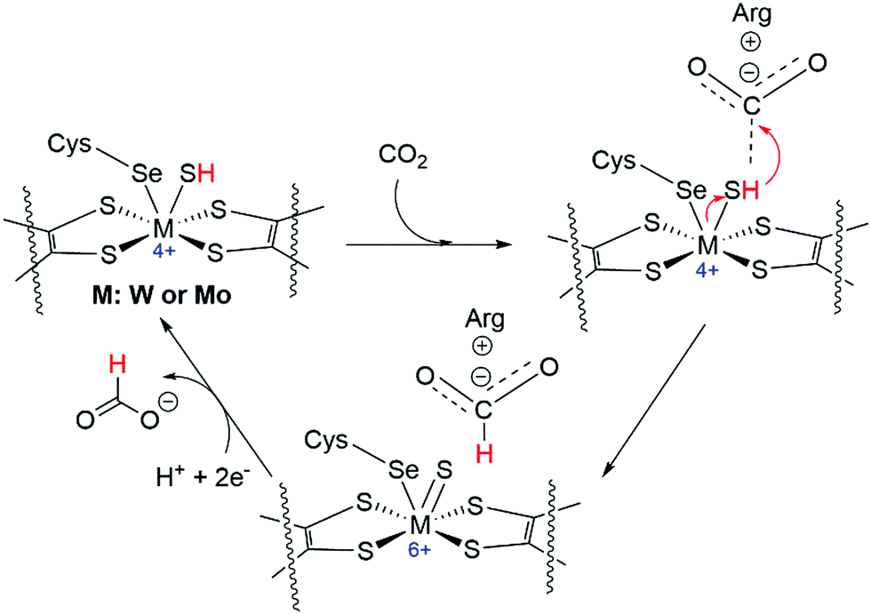 | ||
| Fig. 42 Plausible reaction mechanism for CO2 reduction to formate catalyzed by a selenocysteine-containing FDH.276 The mechanism should be similar for a cysteine-containing FDH. | ||
Inspired by the FDH models (Fig. 41b and 43), several dithiolate-based ligands were developed for the development of biomimetic catalysts, as the metal center is stabilized by two redox non-innocent pyranopterin dithiolate groups (MPT) (Fig. 43). Kim and co-workers prepared a biomimetic WIVO bis-dithiolene complex (136) for the gaseous CO2RR to formate at 90 °C in MeCN (Fig. 43).277 Although the formate production was not stoichiometric, these results were beneficial for providing insights into the importance of the secondary coordination environment and strategies for synthetic modifications. Li, Fontecave, and co-workers synthesized a Ni-complex [NiIII(qpdt)2]− (137) containing a NiS4 motif with two dithiolene ligands mimicking the MPT framework (Fig. 43).278 The catalytic eCO2RR to formate as the major product was achieved with small amounts of CO and H2 on the Hg/Au electrode (not on a GCE (glassy carbon electrode)) and remarkable stability was observed over 23 h of electrolysis with a good overall FE (∼90%; FEFA = 60%). Although 137 performs reasonably well, qpdt2− has two major drawbacks. First, it is not fully biomimetic because the central pyrazine ring is oxidized while it is reduced in MPT. Second, the imines of the qpdt2− ligand are prone to hydrogenation. To rectify these issues, the same team thus synthesized hydrogenated models, more biologically relevant to MPT and more stable.279 The best catalytic performance was obtained for derivative 138 with the reduced imine bond after hydrogenation (Fig. 43). 138 served as the active catalyst for the eCO2RR to formate with an FE of 70% and 300 mV overpotential with negligible H2 generation.
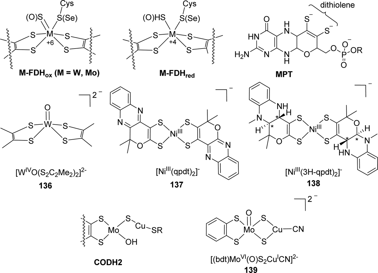 | ||
| Fig. 43 Chemical structures of the biological enzyme active sites and bio-inspired electrocatalysts. | ||
To mimic the active site of CO-dehydrogenase (CODH2) (Fig. 43) to catalyze CO oxidation to CO2 with three sulfur coordination instead of four (as seen in FDH) around the central metal (Mo) of the active site along with 2nd metal Cu, the Mougel and the Fontecave groups prepared a heterobimetallic Mo–Cu active site, [(bdt)MoVI(O)S2CuICN]2− (139; Fig. 43). Mo and Cu are bridged via two μ2-sulfides with the MPT fragment to mimic the benzenedithiolate (bdt) ligand to chelate Mo (Fig. 41).280 The reactivity of complex 139 has a close resemblance with FDH to catalyze the eCO2RR with an FE of 75% for formate generation. IR-SEC and DFT studies revealed a plausible mechanism where the catalytic species is generated via 2e− reduction of 139 in the presence of CO2, triggering the transfer of the oxo moiety to CO2 to give CO32−, and another 1e− reduction. Even though this work established the crucial role of the presence of CuI for the catalytic activity, the detailed functions and interactions between the two metal centers are awaiting further investigation.
The Yang group has demonstrated that Pt-complexes [Pt(dmpe)22+] (140) and [Pt(depe)22+] (141) (depe: 1,2-bis(diethylphosphino)ethane) showed both thermodynamic and kinetic control over metal hydrides for the eCO2RR to formate with high selectivity.172,283 A rapid protonation pathway followed by the exergonic C–H bond forming reaction of the hydride with CO2 may be responsible for the high selectivity. This reasoning was validated experimentally when these catalysts were shown to produce formate selectively upon the eCO2RR in MeCN with an FE of >90% at η < 100 mV without catalyst degradation.
In homogeneous CO2 hydrogenation, various Ir pincer-based complexes have been reported to undergo CO2 insertion into the Ir–H bond to afford Ir–formate complexes/intermediates. Two dihydrido Ir(III) pincer complexes were employed as electrocatalysts by Meyer, Brookhart and co-workers for a homogeneous eCO2RR (Fig. 44).284 (POCOP)IrH2(MeCN) (142) gave an FE of 85% for formate in a MeCN/H2O (95:5) mixture at −1.45 V vs. NHE with a rate constant (kcat) of 20 s−1 without CO. Only a small amount of H2 evolution was observed from the background reduction of water as this active complex was unreactive towards water. However, the role of water was very pronounced in this system to serve as a proton donor to generate OH− to further react with CO2 to form HCO3−. With a slight modification, another Ir complex, (POC′OP)IrH2(MeCN) (143), with an ammonium functional group was designed (Fig. 44).285143 was shown to limit the HER to ca. 7% and thus to allow the use of water as the solvent. Surprisingly, upon addition of 1% MeCN into the aqueous buffer, the over-potential was reduced, and 143 achieved an FE of 93% for formate production at −1.41 V vs. NHE with a CD of 0.6 mA cm−2 for 24 h of the CPE experiment. Mechanistic studies suggested MeCN to be an essential ancillary ligand that ionizes formate effectively to prevent catalyst deactivation. It was also noted that the catalytically active Ir–H intermediates exhibited only modest hydricity to prevent the reaction with water to give H2. Hazari, Palmore, and co-workers further used their hydrogenation catalyst 44 for the eCO2RR in 12% H2O–MeCN under 1 atm CO2 (Fig. 44).286 An FE of >99% to formate was obtained at an onset potential of −1.5 V vs. Fc/Fc+. However, the observed kcat of 0.56 s−1 was much lower than that of 142 (kcat = 20 s−1). Mechanistic studies revealed that the formate elimination from the metal–formate adduct is kinetically difficult, although the CO2 insertion into the Ir–H bond occurs readily.
 | ||
| Fig. 44 Various electrocatalysts for selective electrochemical reduction of gaseous CO2 to formate. | ||
Unlike Ir, there were hardly any rhodium-based electrocatalysts reported to date that can selectively reduce CO2 to HCOOH until the work reported by Turro and co-workers.287 The reported Rh2(II,II) complexes contained two electron-rich deprotonated 6-methyl-2-hydroxypyridine (mhp) bridging ligands and two electron-accepting diamine chelating ligands made of either 1,10-phenanthroline (phen) or dipyrido[3,2-f:2′,3′-h]quinoxaline (dpq) for 144 and 145, respectively (Fig. 44). Electrochemical results showed that selective CO2-to-FA conversion was achieved with 144 but not 145, for which a small amount of H2 was observed under similar experimental conditions. In spite of their nearly identical electronic and atomic structures around the Rh2 core, these two complexes exhibited strikingly different reductive catalysis. These findings highlighted the importance of ligand-based reduction events close to the active metal center(s) to either serve as an electron reservoir and/or to tune the hydricity of the Rh2–H (formed as an intermediate) bond to promote CO2 insertion. Moreover, the protonation of the dpq ligand after its reduction may make that electron unavailable for subsequent catalysis at the metal center. Other than Rh, another 2nd row transition metal complex, PN3–Ru (146), was investigated for the eCO2RR in a 3% H2O–MeCN mixture (Fig. 44). However, unlike Ir-pincer complexes, even though the HER was suppressed, the selectivity for FA was moderate (FEFA = 37.3%) with substantial formation of CO (FECO = 60.7%) at −1.28 V (vs. SHE).288
Development of molecular catalysts based on 1st row earth-abundant transition metals for CO2 electroreduction has been a thriving area since the discovery that [Ni(cyclam)]2+ (cyclam: 1,4,8,11-tetraazacyclotetradecane) (147) catalyzed the eCO2RR-to-formate in DMF in the late 80s by Collin et al.289 These studies have revived enormously in recent years and stimulated new results.170 The Berben group has investigated metal–metal clusters with delocalized bonding within the metal core and electron delocalization extending out to electron withdrawing CO ligands for the eCO2RR.290 An Fe-carbonyl cluster containing an interstitial nitride, [Fe4N(CO)11L]− (148), was found to show poor selectivity towards formate in the presence of a weak acid in MeCN, but good formate selectivity over H2 at a pH of 5–13 in aqueous buffer and in MeCN/H2O (95/5 v/v) (Fig. 45).291,292 The highest efficiency was observed in the neutral buffer reaching a CD up to 4 mA cm−2 with an FE of 96% and a TOF of 106 h−1. Electrolysis experiments as long as 27 h were realized without CO formation, decay in the CD or decomposition of the electrocatalyst, indicative of the exceptional stability. Interestingly, replacing one of the CO ligands with a weaker π-accepting PPh3 group resulted in a significant drop in formate selectivity from 96% to 61%.290
 | ||
| Fig. 45 Fe-based molecular electrocatalysts for selective reduction of CO2 to formate. | ||
Non-innocent redox-active ligands were often employed to achieve exceptional reactivities. Schiff base ligands with a tetradentate κ4-N2O2 coordination framework have been commonly used as catalyst platforms because they are electron-rich, synthetically accessible, and amenable to chirality at the metal center with a judicious ligand design. Machan and co-workers synthesized Fe complex 149 (Fig. 45), utilizing a 6,6′-di(3,5-di-tert-butyl-2-hydroxybenzene)-2,2′-bipyridine (tBudhbpy[H]2) ligand framework. 149 was found to be catalytically competent for the eCO2RR to formate with an FE of 68% for up to 10 h of electrolysis in the presence of 0.5 M phenol (PhOH) as a proton source at −2.5 V vs. Fc/Fc+.293 A small amount of H2 (FEH2 = 30%) along with only trace CO (FECO = 1.1%) was detected to reach mass balance. Mechanistic studies indicated that the phenoxide (PhO−) moieties coordinated to Fe were sensitive to protonation in the reduced state, suggesting the possibility of cooperative pendent proton interactions being involved in the CO2 reduction. Intrigued by these observations, other ligand derivatives, (Mecrebpy[H]2) and (tBucatbpy[H]4), containing pendant 2nd sphere H-bond donor (–OMe) and acceptor (–O−) groups were employed for complexes 150 and 151, respectively (Fig. 45).294 By tuning the ability of the secondary sphere moiety to direct the exogenous sacrificial proton donor PhOH to the proton-sensitive Fe-bound O atom, an increased CD for formate production (jHCO2−) and selectivity for formate were achieved. While a 3.3-fold enhancement of the CD with an FE of 85% was observed for 150 in comparison to that of 149, for 151, the CD increment was only 1.2-fold with no significant increase in FE (ca. 71%), suggesting that the strength of interaction between the external proton donor and the pendant relay site has a nuanced effect on the reaction control. Overall, these results indicated that the improved performance in both activity and selectivity for the –OMe derivative arises from the beneficial interactions between the secondary sphere moieties, exogenous H+ donor, and inner-sphere Fe-bound O atom, which collaboratively contribute to the preconcentration of the H+ donor and kinetic selectivity.
Fe porphyrin (Fe-porp) complexes have been extensively studied in the field of the homogeneous eCO2RR as they are efficient and robust in the low-oxidation state. However, it is noteworthy that these complexes are prone to produce CO as the only product in organic medium.295,296 Nocera and co-workers judiciously adopted an approach to introduce an external tertiary amine ligand to FeTPP (TPP = tetraphenylporphyrin) (152) in the presence of a weak proton donor to drive the reduction of CO2 to formate from Fe(0)TPP with a moderate selectivity of ca. 70% (Fig. 45). In contrast to those conventional CO2-to-formate generating organometallic systems that involve the initial formation of M–H species followed by CO2 insertion, this system preferentially forms an initial Fe–CO2 adduct followed by subsequent protonation. The advantage of such a protonation mechanism is to avoid the HER and produce formate with enhanced selectivity. The presence of the tertiary amine appears to increase the basicity of CO2 bound to the Fe center, allowing for its protonation, and facilitated dissociation of formate, consistent with a trans effect. Thus, the results open an alternative route for an unexplored CO2-to-formate conversion mechanism and shed light on the role of the trans effect in redirecting the eCO2RR from CO to formate.
Robert, Lau and co-workers studied the eCO2RR with [CoN5]2+ (N5 = 2,13-dimethyl-3,6,9,12,18-pentaazabicyclo-[12.3.1]octadeca-1(18),2,12,14,16-pentaene) (153) and obtained exclusive CO formation in DMF (Fig. 46).297 Intriguingly, the selectivity was completely changed to FA without CO when the central metal Co was replaced by Fe in [FeN5Cl2]2 (154). Experimental results along with DFT calculations revealed that, in the case of the Co–CO2H intermediate, π-back-bonding from the electron-rich, formally CoII center to π* orbitals of CO2 would weaken the C–O bond and hence facilitate its cleavage to give the CO product.
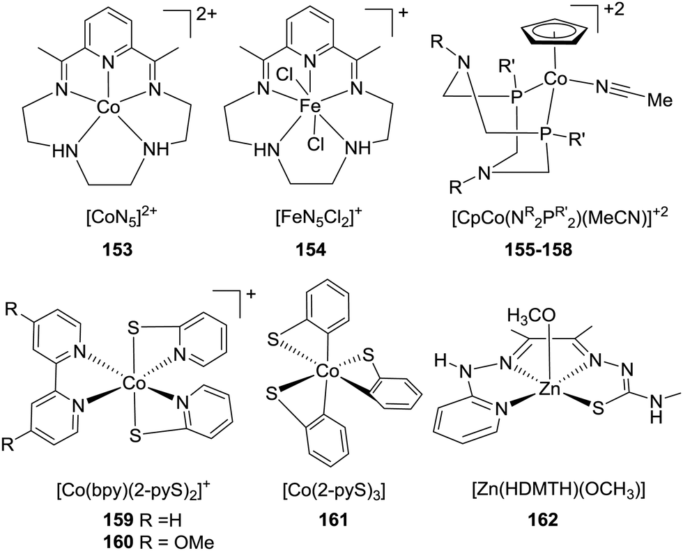 | ||
| Fig. 46 1st row transition metal-based electrocatalysts for selective reduction of gaseous CO2 to formate. | ||
Roy et al. designed a family of Co-based catalysts, [CpCo(NR2PR′2)L]n+ (L = I, MeCN; NR2PR′2: 1,5-diaza-3,7-diphosphacyclooctane) possessing four different NR2PR′2 ligands with cyclohexyl or phenyl substituents on phosphorus (PCy or PPh) and benzyl or phenyl substituents on nitrogen (NBn or NPh) (155: RPh, R′Cy; 156: RPh, R′Ph; 157: RBn, R′Cy; 158: RBn, R′Ph) (Fig. 46).298 These complexes were found to be very efficient for the eCO2RR towards FA with very high selectivity (FE = 90 ± 10%) at moderate overpotentials of 400–600 mV in DMF. An outstanding TOF of >1000 s−1 was observed for 157, likely due to the presence of the most electron-donating phosphine and basic amine groups among all 4 complexes. Mechanistic studies suggested that while the intramolecular pendant amines were not involved in the direct proton transfer to CO2, they help to stabilize key intermediates through H-bonding interactions with water molecules in the hydride transfer step.
With an idea of making the eCO2RR more energy efficient by reducing the overpotential, Fontecave, Mougel, and co-workers synthesized two variants of (bpy)bis(2-pyridinethiolato)Co(III) complexes (159–160) which were identified as highly active and selective catalysts for formate production (Fig. 46).299 The selectivity for formate production reached 57% with a TOF of 27.5 s−1 for 159 at −1.83 V vs. Fc/Fc+, and 64% with a TOF of 29.5 s−1 for 160 at −1.98 V vs. Fc/Fc+, respectively. These results indicate that the introduction of the electron-donating –OMe group on the bpy moiety does not significantly increase the rate and selectivity of the reaction despite driving the operating potential to more negative values. Furthermore, when the bpy ligand was replaced by 2-pyridinethiolate (161), a TOF of 178 s−1 was achieved but at the cost of a highly negative cathodic potential, making the overall reaction less energy efficient (Fig. 46). Benchmarking of these complexes including previously reported molecular catalysts allowed complex 159 to stand among the best reported CO2-to-FA catalysts, achieving a TOF of 10 s−1 at an η of 110 mV only, which is the lowest value reported so far.
Reduction of the metal center in the 1st step of the catalytic cycle and subsequent formation of catalytically active metal-hydride species are the common steps found within almost all the molecular electrocatalysts discussed here during the eCO2RR where metal centered catalysis is considered. Furthermore, saturated CO2 solutions are required for these complexes to obtain meaningful catalysis, which may prevent them from being used for practical purposes. Grapperhaus and co-workers have designed a redox-inactive zinc-based complex, [Zn(HDMTH)(OCH3)] (DMTH = diacetyl-2-(4-methyl-3-thiosemicarbazonate)-3-(2-pyridinehydrazonato)) (162), for converting CO2 from air to formate as the only C1 product, although the FE for formate production was unsatisfactory (ca. 15.1% based on the total charge) (Fig. 46).300 It is noteworthy that this complex utilized metal–ligand cooperativity and redox-active ligands to sequester and activate CO2 without being reduced and this may serve as a new strategy to mitigate the CO2 issue if the performance can be uplifted dramatically.
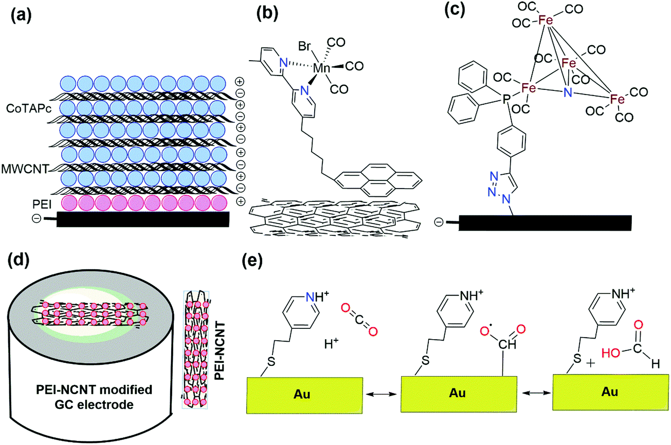 | ||
| Fig. 47 Schematics of various catalysts immobilized on modified electrode surfaces reported for electrochemical reduction of CO2 to FA: (a) GE-(MWCNT/CoTAPc)n;302 (b) pyrene functionalized Mn-modified CNTs;303 (c) alkyne-terminated [Fe4N(CO)12]− on azide functionalized GC;304 and (d) PEI–NCNT/GC.307 (e) Proposed formate formation mechanism for the 4-PEM-modified Au electrode.308 | ||
Reisner et al. installed a pyrene unit in the bpy arm of [MnBr(2,2′-bpy)(CO)3] (87) to immobilize the complex on a CNT electrode.303 Unlike the above-mentioned multilayer formation, only single layers were generated in this case with varied catalyst concentrations. While the Mn-modified CNT electrode favored the formation of formate under fully aqueous conditions at a low Mn-catalyst loading, CO was produced upon increasing the catalyst loading (Fig. 47b). The TON for this hybrid electrode reached up to 3920 for formate at an overpotential of 590 mV vs. SHE, albeit with a low FE. These observations suggest that the selectivity of the eCO2RR products is sensitive to the surface loading of the catalysts. In a similar fashion, the Berben group has modified complex 148 with a terminal alkyne to use azide alkyne cycloaddition to immobilize the complex onto an azide-terminated GC electrode to further increase the stability of the catalyst (Fig. 47c).304 Indeed, during the CPE experiment with the modified electrode, no degradation was observed for at least 4 days. An FE of 75 ± 20% and a TON of 52500 were achieved at −1.25 V vs. SCE in a pH 9 buffer.
Using the inherent surface activity of NCNT, Zhang et al. deposited SnO2 on NCNT to form a composite, which has been further used to modify a GCE (SnO2-NCNT/GCE).305 In comparison to the electrode without SnO2 (NCNT/GCE), both electrodes were capable of reducing CO2 electrochemically to formate in CO2 saturated 0.1 M KHCO3 aqueous solution, but SnO2-NCNT/GCE has much higher activity. At −0.9 V vs. Ag/AgCl, an FE of 46% was obtained for SnO2-NCNT/GCE, but an FE of only 10% was reached for NCNT/GCE. Li et al. prepared a novel Bi-MWCNT-COOH/Cu catalyst via a facile co-electrodeposition technique on Cu foil to selectively electrocatalyze CO2 reduction to produce FA.306 The as-prepared electrodes exhibited high catalytic activity, stability and selectivity toward the production of FA. FEFA could reach values up to 91.7% at −0.76 V vs. RHE, with no obvious degradation after 12 h of continuous electrolysis. The presence of an inherently conjugated-conductive body with an H-bonded sequence served as effective catalytic centers for the eCO2RR.
Similar to the work reported by Zhao et al. (vide supra) on PEI and MWCNT modified electrode surfaces,302 the Meyer group employed PEI as a co-catalyst on top of a metal-free N-doped CNT (PEI–NCNT) to conduct the eCO2RR to formate.307 This strategy unlatches a new avenue for the metal free eCO2RR. During the stepwise electrode fabrication, the homogeneous CNT suspension was first spin coated on a GC electrode followed by nitrogen doping to afford NCNT/GC. Finally, a PEI overlayer was applied to NCNT/GC by dip-coating to procure the PEI–NCNT/GC electrode (Fig. 47d). NCNT/GC is an effective electrocatalyst for CO2-to-formate, and the use of additional PEI reduced the overpotential by 200 mV with higher FE and CD for formate production. An FE of 85% for formate could be achieved with a steady-state CD of 7.2 mA cm−2 in CPE experiments at −1.8 V vs. SCE for 24 h in aqueous buffer.
Inspired by the aforementioned seminal work on metal-free catalysis, Coskum et al. reported an all-organic, metal-free electrocatalyst polydopamine (PDA) that, when immobilized on large-surface, sponge-type carbon felt, achieved impressive performance with a geometric CD of 18 mA cm−2 at a 210 mV overpotential for CO (minor) and formate production for continuous 16 h of operation with an FE of >80%.309 In this particular conjugated polymer based electrocatalyst (PDA), hydrogen bonded motifs have been observed, similar to those in enzymes. Interestingly, PDA shows a lower η than those of state-of-the-art formate selective elcetrocatalysts (e.g. 0.5 V for Ag at 18 mA cm−2) on the carbon-based nonmetallic carrier cathode. As the field of metal-free eCO2RR catalysis is flourishing, Flake and co-workers have taken advantage of the Au–S interaction to modify a blank gold electrode with monolayers of thiol-tethered ligands such as 2-mercaptoproponic acid (2-MPA), 4-pyridylethylmercaptan (4-PEM) and cysteamine (CYS) to drive the eCO2RR.308 Remarkably, Au electrodes modified with 4-PEM showed a 2-fold increase in the FE and 3-fold increase in formate production relative to the best results with untreated Au foil in 0.1 M KHCO3 buffered at pH 6.8 (Fig. 47e). Conversely, electrodes with 2-MPA showed an FE of nearly 100% towards the HER, while CYS-modified electrodes showed a 2-fold increase in both the CO and H2 production. A proton-induced desorption mechanism was proposed for the 4-PEM modified Au. At the same time, the inability of the other two electrodes to produce significant formate was believed to be associated with the pKa of the surface-tethered functional groups. These results illustrate that the product selectivity of the eCO2RR may not always be governed by the electrodes, and/or electrolytes.
After all these discoveries, several groups were working relentlessly in exploring high-performance composite materials containing other non-metals besides carbon. The Wang group first used 2D nonmetallic black phosphorus nanosheets (BP NSs) as a substrate for the eCO2RR to FA with a maximum yield rate of 22.7 cmol dm−3 h−1 and an FE of 25.8% at −1.3 V vs. RHE.310 To conquer the low-performance and enlarge the electrochemical applications of BP NSs, BP NSs were prudently utilized as the catalyst support to load metals by electrodeposition to fabricate an electrodeposited Bi dendrite/BP NS composite (ED-Bi dendrite/BP NS). This composite achieved the highest FA production rate of 440 ηmol dm−3 h−1 and an FE of 92% at a lower potential of −1.0 V vs. RHE, both significantly higher than those of ED-Bi dendrites without BP NSs. These observations suggest that BP NSs are a promising substrate to fabricate metal composite catalysts for improving CO2 electroreduction.
3.5. Design of the electrolytic cell/reactor
In addition to the aforementioned factors and parameters, reactor design is another indispensable facet that often helps to improve the overall cell performance, particularly by increasing the PCDs, FEs, and stability. The reactions occur in the electrolytic cell owing to the difference between the imposed external voltage and the open-circuit potential of the cell. With the invention and subsequent progression of CO2 reduction, different cell designs have been evolved and modified accordingly depending on the specific needs.311,312 In this section, only those cells will be discussed in detail that primarily produce FA as the main product over other CO reduction products. In this regard, the electrolytic cells can be categorized into H-type cells, bench-scale continuous reactors, undivided fixed-bed reactors, flow cell reactors, etc.To date, commercially available or customized H-type cells are still the most common and well-known lab-scale reactor for the eCO2RR, in which the working and reference electrodes are placed in the cathodic compartment while the counter electrode is placed in the anodic compartment (Fig. 48a). These two compartments are then connected through a channel (showing a typical “H” form) and separated by an ion-exchange membrane to prevent the reduction products from getting oxidized during electrolysis. CO2 gas is continuously flowed into the cathodic segment via a glass frit and then delivered into a gas chromatograph (GC) to detect the gas products. In contrast, liquid products are collected from the electrolyte after the electrolysis process and detected using NMR or HPLC. Compared to gaseous products, the FEs for liquid products such as FA are low. Hence, the electrolysis time at constant potential together with the volume of the cell should be increased to reach detection limits of HPLC or NMR. The Koper group has used a custom-made H-type cell with two compartments separated by Nafion 115 where Pd70Pt30/C NPs were loaded on a carbon substrate for the eCO2RR.247 The maximum PCD of 5 mA cm−2 could be achieved with an 88% FE at a 400 mV overpotential. In 2016, Wang and coworkers investigated the eCO2RR using a series of electrodeposited Sn catalysts on Cu film with controlled deposition current density in an H-type three-electrode cell (Fig. 48a).313 The maximum FEFA was 91.7% at −1.4 V vs. SCE with an initial CD of ∼0.9–1.4 mA cm−2 in aq. KHCO3 solution saturated with CO2. With the progression of the electrolysis time, the reaction current exhibited a slow but continuous decrease, and the FE dropped to 81.6% after 2 h. When the experiments finished after 3 h, CD decreased to 0.7 mA cm−2 with an FEFA of 69.6%. The degradation of the Sn electrode with a concomitant decrease in performance is likely due to the formation of an alkali metal intermetallic during long period electrolysis. Despite wide utilization, H-cells with metal plate electrodes often suffer from serious drawbacks including limited surface area, large interelectrode distance and poor cell performance and are not optimized for full-cell operation. In general, an H-type cell is a suitable batch reactor for catalyst screening and product quantification. However, for further industrial applications, efficient cells with lower resistance and higher mass transfer efficiency are essential.
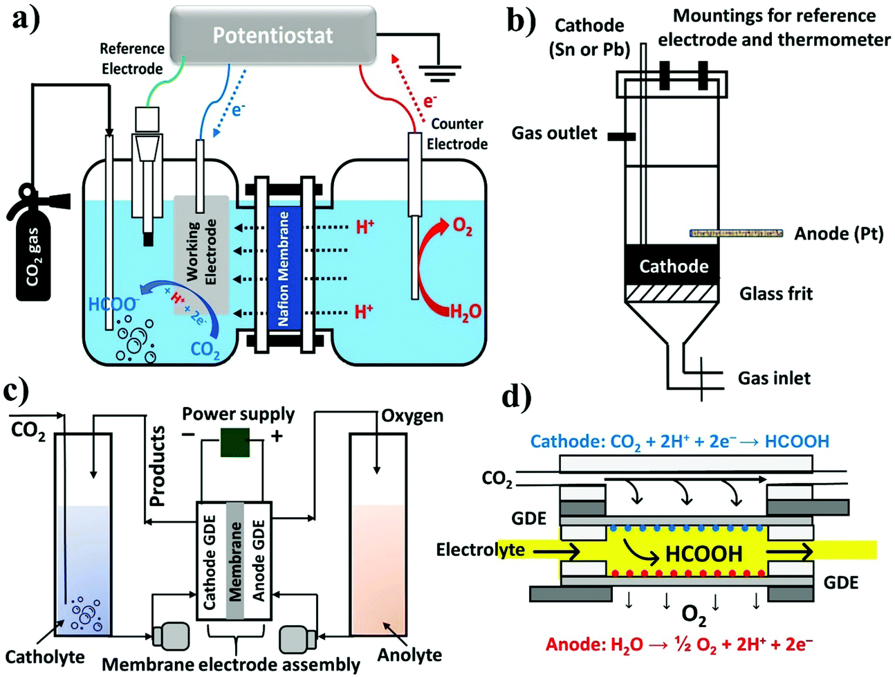 | ||
| Fig. 48 Schematic diagrams of (a) the conventional H-type electrochemical cell, (b) undivided fixed-bed reactor, (c) liquid phase flow cell consisting of an MEA and (d) microfluidic reactor for CO2 conversion to FA/formate. | ||
To overcome these shortcomings, rectangular-type reactors were introduced that can extend the electrode surface within a small cell volume and reduce the inter-electrode gap in order to minimize ohmic losses. Initially, Yamamoto et al. examined the eCO2RR in a rectangular cell with an increased electrode surface area (4 cm2) and relatively small inter-electrode gap (1–2 mm).314 Although syngas was the primary CO2 reduction product at the cathode along with O2 evolution at the anode, the design idea of a rectangular-type reactor was implemented for subsequent development in FA production. Oloman's group reported the eCO2RR in a laboratory bench-scale continuous reactor with the co-current flow of reactant gas and catholyte liquid through a fixed-bed cathode of 30# mesh tinned-copper.315 This set-up could alleviate the CO2 solubility constraint, generating formate as the primary product; however, unsatisfactory η and rapid deterioration of the cathode encouraged the development of other cell designs. While most CO2 reduction to FA using metal plate electrodes has been conducted in divided H-cells, Köleli et al. proposed to use an undivided fixed-bed reactor to reduce CO2 at Pb and Sn granules, aiming to extend the geometric surface area as much as possible within a relatively compact electrochemical cell volume with a small electrode gap and high faradaic efficiencies (Fig. 48b).188
For the eCO2RR to become an industrially feasible and profitable process, batch electrochemical cells should be upgraded to flow cells that could attain >100 mA cm−2, surmounting the mass transfer limitations of an H-cell by continuously circulating the reactants and products. Moreover, the gas-phase eCO2RR is feasible within a flow cell to conquer CO2 solubility issues and product recycling from the aqueous phase. Even the thermodynamics and kinetics of the eCO2RR within flow cells are fundamentally different compared to H-type cells. In 2013, Wu et al. reported a design of a full electrochemical flow cell featuring a buffer layer of circulating liquid-phase electrolyte.316 Incorporation of the buffer with an electrolyte significantly enhanced the formation of formate, suppressing H2, which was predominant in the absence of the buffer. FEmax toward formate was >90% at −1.7 V vs. SHE with a PCD of 9 mA cm−2 when the anode was fed with H2. When H2 was replaced with 1 M KOH solution, FEmax toward formate was 85% at −2.0 V with a PCD of 6 mA cm−2. This study proved that the circulating buffer enables the production of formate at an η of 200 mV regardless of the gaseous or aqueous reactants at the anode. Polymer electrolyte membrane (PEM) flow cells, closely related to proton exchange membrane fuel cells (PEMFCs), are one of the most explored class of CO2 flow cells, which utilize a membrane electrode assembly (MEA), developed from fuel cell systems.218,312,317,318 The MEA, a vital component of the cell, consists of a PEM, cathode GDE, and anode GDE where the electrodes are separated to prevent the contamination of products but are in close proximity to decrease the cell resistance (Fig. 48c).
Although formate production has been extensively studied with MEA reactors, particularly with Sn electrocatalysts, the obtained current density was inadequate for scalable technology.225,315,316,319 Very recently, Lee et al. reported a facile strategy of a catholyte-free MEA flow cell using vaporized CO2 gas as a reactant where a significantly high formate concentration of 41.5 g L−1 has been obtained at 343 K with a high PCD of 51.7 mA cm−2 and FEFA of 93.3% via continuous operation in a full flow cell at a low cell voltage of 2.2 V.320 Interestingly, the catholyte-free eCO2RR using a GDE with commercial Sn NPs showed higher activity compared to the 1.0 M KCl catholyte-added system. Meanwhile, He and co-workers realized the utility of a buffer layer in proton exchange membrane reactors (PEMRs).321 It was suggested that a buffer layer helps to ensure sufficient cathode potential, which is essential to CO2 activation. Notably, the cathode potential could not break through the threshold in the conventional PEMR without a buffer layer due to a large portion of potential consumption on the PEM. While when using commercial Sn with a GDE a PCD of 150 mA cm−2 with 60% current efficiency could be achieved within 0.5 h of electrolysis in 0.5 M KHCO3 buffer solution, the efficiency dropped to only 5% without the buffer layer. Although the previous examples of using MEA or PEMRs for FA/formate production have been proved beneficial, the corrosive nature of FA towards the membrane during long-term electrolysis can be a major concern that ultimately impedes commercial use.322 However, a large scale MEA cell was prepared by Oloman's group where a geometric surface of 320 cm2 for a Sn-based GDE with a concomitant jFA of 195 mA cm−2 could be attained.323 For a superficial j of 0.6–3.1 kA m−2, the formate current efficiencies varied from 91 to 63% for the applied reactor voltage of 2.7–4.3 V, which produced up to 1 M formate in the catholyte product from a single pass. Unfortunately, a gradual decrease of the catalytic activity was also observed after 100 min of operation, likely due to formate crossover through the Nafion 117 membrane. Moreover, additional operating costs would be required for this kind of large cell, which typically operates at 600 kPa and 325 K. The examples discussed in this review typically use CO2 either as a gas or dissolved in aqueous media for cathodic reduction. Unfortunately, both the feedstocks encounter challenges when CO2 electrolyzers are scaled up for pilot plant and/or industrial operations to produce chemicals and fuels. While aqueous CO2 offers significantly low solubility precluding CO2 from reaching the cathode for the reaction, gaseous CO2 feedstocks require strikingly high energy for purification and pressurization to achieve meaningful rates of product formation. To circumvent these issues, the Berlinguette group has used liquid bicarbonate feedstocks that can deliver high concentrations of CO2 to the cathode for CO2-to-FA conversion.324 Although electrochemical reduction of bicarbonate into formate was firmly established by the Hori325 and Kanan240 groups, their activities were not noticeable. On this front, the Berlinguette group has designed a continuous flow cell fitted with a BPM and a Bi cathode electrocatalyst supported on CP where bicarbonate solutions (3.0 M KHCO3(aq)), forming CO2 upon reacting with H+ at the catalyst interface, can be converted into formate at a CD of 108 mA cm−2 (FE ∼64%). This result has been benchmarked and compared with the state-of-the-art performance of gaseous-fed CO2 electrolyzers. In spite of the significant progress in the field of flow cells, further research is necessary in ameliorating the cathode lifetime, reducing formate crossover and optimizing the reactor for the eCO2RR to FA production.
Most of the aforementioned electrolytic cells, designed on the basis of fuel cells, utilize a PEM as the electrode (cathode and anode) separator. More recently, a state-of-the-art concept of the microfluidic flow cell (MFC) for the eCO2RR was first modeled and propounded by the Kenis group where a flowing electrolyte stream, instead of an ion exchange membrane, is used to separate the cathodes and anodes (Fig. 48d).326 This MFC configuration separates the oxidation and reduction products by diffusion and not by the membrane. Microfluidics is a powerful technique and offers a high surface-to-volume (S/V) ratio along with efficient heat and mass transfer rates. Hence, leveraging the benefits of microfluidics to address existing energy and environmental issues would be propitious. In 2010, Kenis reported the fabrication of an MFC as a versatile analytical tool for an efficient eCO2RR to FA using different catalysts and operating conditions, notably different pH values (pH 4–10). Furthermore, the cell, consisting of a Sn coated GDE, serves as an effective reactor with significantly high efficiencies (FE ∼89% and energetic efficiency ∼45%) and PCDs on the order of 100 mA cm−2, pH 4 being the most effective. But lower pH was deliberately avoided because Sn dissolves in a highly acidic medium. In addition to Sn catalysts, a BiOBr catalyst has already been shown by the Sargent group to exhibit good eCO2RR activity in an H-cell configuration but limited by mass transport phenomena (vide supra).227 To this end, BiOBr was deposited onto a GDE carbon electrode, which thereby achieved high formate selectivity (over 90%) with a PCD as high as 200 mA cm−2 in an MFC configuration, showing the distinct advantages and importance of gas-phase reactors over liquid-phase reactors.
Although it is evident from the discussions above that the design of the electrochemical cells and/or reactors for CO2-to-FA conversion is one of the principal parameters which has seen significant surveillance in the past two decades, the application of the eCO2RR is still in a laboratory research stage. Despite the low CO2 solubility and mass transfer limitations causing low current densities, H-type cells (liquid phase) are being tremendously used, which provide fundamental lessons for catalyst development in a flow cell (gas-phase) system. In order to obtain a high current density with enhanced long-term stability, further development of flow cells would be necessary, which can be a future gateway of the eCO2RR towards industrial application at a large scale. Besides, there are still some other determining factors related to flow cells such as the channel length, flow rate of the CO2 stream, anode materials and catalysts, easy separation of products, purity of the inlet gas, etc. that seek immediate attention for developing CO2 electrolyzers, particularly for the R&D sector.
3.6. Towards practical systems for electrochemical FA production
The ultimate goal is to develop the means to construct cheap, scalable and energy efficient systems for the eCO2RR.327–330 This will enable the wide scale adoption of this technology and a significant contribution towards carbon utilization towards value added products such as formic acid.331,332 Thus far, we have covered a range of significant advances in the eCO2RR, which have been accomplished by tuning reactions conditions such as the system, solvent/electrolyte, operating pressure, pH, electrode, and catalyst. Thus far in the literature, these conditions have been independently optimized. However, in the actual system, these are likely to be coupled and have an effect on each other. It is therefore crucial that the relationship between these conditions be considered, to guide future optimization and design efforts. Of the most commonly employed configurations for the eCO2RR as covered in the previous section, MEA systems offer the highest energy efficiencies due to the ‘zero-gap’ configuration, leading to lower ohmic losses.333,334 In addition, various engineering approaches have shown that an MEA system can be used to produce pure liquid product solutions.185,186 These factors highlight the MEA as the system of choice for future practical and large-scale application of the technology. This is analogous to proton exchange membrane (PEM) electrolyzer systems for hydrogen production,335 which have been successfully commercialized. To enable high current density, MEA systems used for the eCO2RR typically are catholyte-free, relying on the ion exchange membrane as the medium for ion transport to/from the catalyst.320,333 In such systems, the choice of catholyte is thus not a reaction condition that can be optimized. As for the anolyte, aqueous media are most commonly used to facilitate water oxidation to liberate oxygen.331 There has also been interest to replace water oxidation with organic oxidation reactions in order to reduce the energy requirements of the overall process and also to generate valuable products. Good recent examples in the literature include the partial anodic oxidation of glycerol and ethylene.336–338 Reports involving high pressure setups involving flow cell/MEA systems for the eCO2RR have been rare.339,340 In theory, such systems should enable the maximum possible availability and transport of the CO2 reactant to the catalyst. As a result, this can likely translate to unprecedented current density and selectivity. Furthermore, work by Sinton and co-workers showed that pressurization up to 10 bar enables system tolerance towards significant amounts of O2 impurities that are expected to be present in typical flue gas.341 As a result, such high-pressure gas diffusion-based systems have strong motivation for future development and are an avenue for intense research.Under conditions of high current density in gas-diffusion systems, it is expected that the local pH at the electrode surface will become highly alkaline.342 However, the high concentration of OH− can react with CO2 and form carbonate, which gives rise to two crucial issues. (1) Consumption of CO2 feedstock, thus limiting CO2 conversion yields. (2) Decreased CO2 reactant available for CO2 conversion. Thus, future research efforts should focus on solving the carbonate issue. Promising reaction directions to solve this include the use of an acidic electrolyte or development of efficient bipolar membranes.343,344 As for the design of catalyst materials, the majority of studies in the literature test their catalysts predominantly in traditional H-cells rather than using gas diffusion electrodes. However, there is a concern about how readily catalysts optimized under ‘H-cell’ conditions translate into practical MEA device systems. For example, in the fuel cell community, catalysts designed for the oxygen reduction reaction in an H-cell do not perform as well in the actual device.345 Thus, moving forward, catalyst testing and design should be carried out in gas diffusion systems. Finally, with regards to the electrode, it is crucial that designs can last for a long period of continuous operation (>10000 h and beyond). An important aspect of the gas diffusion system is the three-phase region, made possible by the hydrophobic support. Thus, future research should focus on optimizing this three-phase region and prevention of flooding by maintaining the hydrophobicity of the support. It is also crucial to increase single pass efficiencies, thus increasing CO2 conversion yields.346 Finally, there should also be a focus on scaling up (Fig. 49a)343 and developing electrolyzer cell stacks (Fig. 49b),347 towards the future practical application of this technology.
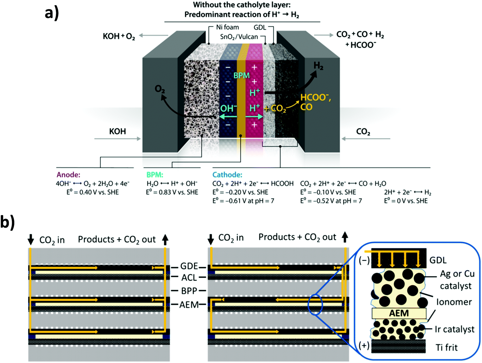 | ||
| Fig. 49 (a) Schematic of a larger scale (25 cm2 active area) CO2 electrolyzer for production of formic acid.343 (b) Illustration of an electrolzyer cell stack for electrochemical CO2 conversion.347 | ||
4. Economic analysis of formic acid synthesis from CO2
4.1. General background
Conventionally, FA is mainly manufactured using the following four resource-intensive and high carbon footprint methods: (1) methyl formate hydrolysis, (2) oxidation of hydrocarbons, (3) hydrolysis of formamide, and (4) preparation of free FA from formates.348 Method 1 is the most common route, which is based on a two-stage process (eqn (8) and (9)). The carbon emission of the conventional method is around 2.2 kgCO2 kgFA−1.| CO + CH3OH → HCOOCH3 | (8) |
| HCOOCH3 + H2O → CH3OH + HCOOH | (9) |
FA is mainly used in textiles, pharmaceuticals and food chemicals, due to its strong acidic nature and reducing properties.348,349 The current market price of 95% grade FA is around $600–$1000 per ton, and the global production in 2019 was estimated to reach 1.015 megatonne with a projected annual growth of 1–3%.350 However, this market prediction has not considered the application of FA as a hydrogen energy carrier. Under such a perspective, the size of demand could reach a multi-gigatonne scale in order to achieve a meaningful capacity for renewable energy storage and utilization.329 FA synthesis from CO2 requires both CO2 capture and utilization (CCU) processes, which can be split into three steps: (1) capture of CO2 and generation of H2 by electrolysis, (2) utilization via CO2 hydrogenation or the eCO2RR to formic acid, and (3) final FA product purification, as illustrated in Fig. 50.
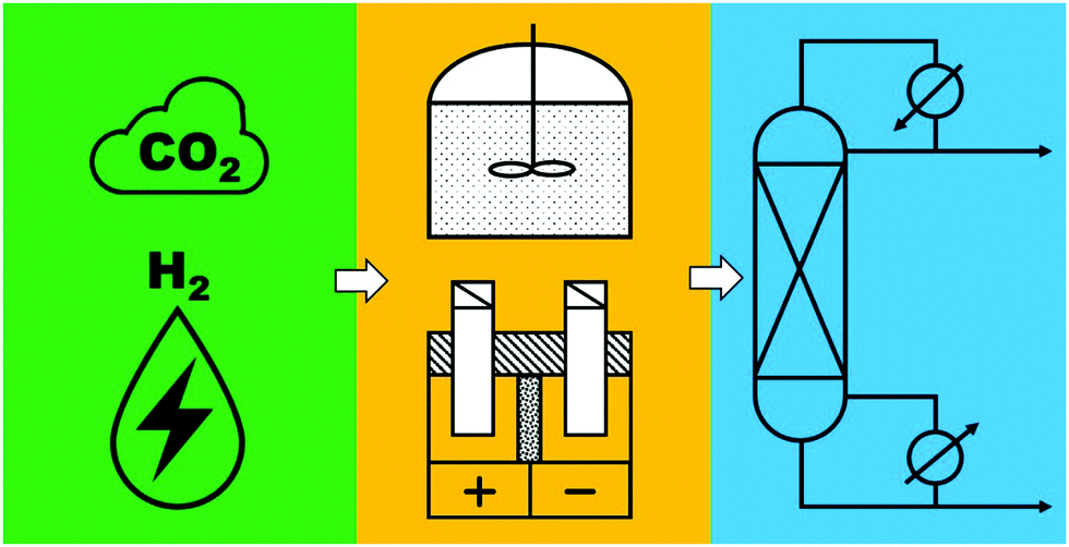 | ||
| Fig. 50 A general CCU process for converting CO2 to formic acid. | ||
For the carbon capture step, the mature technology is amine scrubbing. Many other methods are also under development, including adsorption from flue gas, direct air capture, chemical looping, membrane separation, cryogenic separation, etc. The cost for amine scrubbing is around $37–121 tonCO2−1,351–353 but, by using membrane technologies, it has the potential to reduce to $25 tonCO2−1.353,354 To achieve low carbon emission, electrolysis of water is the most common way in addition to the direct eCO2RR. If in the utilization step the CO2 hydrogenation approach is used, both CO2 and H2 may need purification to avoid catalyst poisoning, and compression to reach the reaction pressure. On the other hand, if an eCO2RR method is employed, water can feed directly as a reactant and H2 generation in the capture step is not necessary. Thus, as we discussed in the last two sections, for the utilization process, three synthetic routes can be employed for consideration: (1) homogeneous catalysis and (2) heterogeneous catalysis for CO2 hydrogenation, and (3) the eCO2RR using renewable electricity, although the maturity of all these methods is still at technology readiness levels (TRLs) of 3–5.
Comparatively, the hydrogenation process is more developed than electrochemical reduction, although two pilot-scale electrochemical reduction plants were demonstrated by Det Norske Veritas (DNV) and Mantra Venture Group.349,355–357 Thermodynamically, FA synthesis from CO2 and H2 has a positive Gibbs energy of 32.9 kJ mol−1. Therefore, controlled by chemical equilibrium to improve the yield, it is required to conduct the reaction either under a high pressure of more than 100 bar, and/or under basic conditions to form formate. As discussed earlier, homogeneous catalysts have high reactivity and selectivity, but the process requires one to recover the catalyst from the product stream. In this sense, heterogeneous catalysts are more advantageous, but their reactivity and selectivity are typically lower. Electrochemical reduction can be carried out under mild conditions, and it can be further directly coupled with renewable electricity from solar and wind power plants. While the cost of renewable energy can be as low as 2 cents kW−1 h−1, currently high FEs can only be realized under very low FA concentrations in the product stream. Therefore, a significant amount of energy may be required to purify FA to reach the application requirements. In this regard, distillation is the most common purification method. As FA has a very close boiling point to water, an amine is often used as an extraction agent and regenerated through a reactive distillation process, but it is still an energy-intensive step since the amine forms an azeotrope with FA.
4.2. Life cycle assessments
Several economic analyses and life cycle assessments (LCAs) of the CDU (carbon dioxide utilization) to FA process have been reported in the literature. As most of these studies are based on laboratory scale experimental data to estimate the process parameters, attention should be paid to the technical gaps between the laboratory and industrial processes in terms of the production scales. Nevertheless, these studies have shed light on different aspects and helped to identify the most important issues for future studies to focus on.Pérez-Fortes et al. conducted the first comprehensive techno-economic analysis of the CDU to FA process.349 In their model, CO2 is captured by amine scrubbing as a worst-case scenario and H2 is generated from water electrolysis. The FA production is conducted by homogeneous catalysis using a Ru- or phosphino-based catalyst via the formation of an amine–FA adduct based on data from a patent,358 and the final product is purified to 85 wt% through reactive distillation. The net present value (NPV), a metric to evaluate the profitability, was positive when the FA price was higher than €20141700 per ton, which is approx. twice the current market price. However, the carbon footprint (CF) of only 0.166 kgCO2 kgFA−1 is much lower than that from the conventional FA process. Notably, the major cost is the high price of the Ru catalyst. When the price of consumables (including catalysts) is decreased by a factor of 6 (achieved by future R&D), with renewable electricity, the price to make CDU to FA profitable is close to the current market reference. Realizing the high catalyst expense and the heavy energy requirement during purification, Kim and Han further studied and compared two proposed processes.359 Process A is similar to that by Pérez-Fortes, but process B uses an Au/TiO2 catalyst, to replace the more expensive Ru system, and an amine-shift process to break the azeotrope to save the purification energy. Process design simulations showed that process B increased the energy efficiency by 24.3% and reduced CO2 emission to 0.3 kgCO2 kgFA−1. However, process B has a much longer process time, which results in a slightly higher cost than that of process A. Aldaco et al. combined a dynamic LCA with economic analysis to explore the potential transition from carbon capture and sequestration (CCS) to CCU.360 The CCU process used here was again similar to what was studied by Pérez-Fortes.349 It was found that while CCS yields a greater reduction in CO2 emissions than those of CCU scenarios and the conventional FA production processes, CCU offers better economic potential and lower fossil consumption, especially when powered by renewable electricity.
Sadhukhan and co-workers considered the integration of the CDU to FA process with a bioelectrochemical system (BES) for wastewater treatment.361 The BES unit removes the chemical oxygen demand of wastewater and generates CO2 and electricity. The liberated CO2 is electrochemically reduced to FA in the CCU process. The economic analysis suggests that the production cost of FA will be around €2018500–1500 per ton. While the purification cost was not considered in this study, the process is valuable because of the integrated framework combining wastewater treatment and energy production. Baena-Moreno et al. evaluated the CCU process using CO2 captured from biogas containing 40% CO2 and 60% methane.362 A membrane technology is used for CO2 capture. H2 is generated from water electrolysis by a renewable electricity source. Similar to other analyses, FA is produced by homogeneous catalysis and purified by reactive distillation to reach 85 wt%. The economic analysis shows that at the production scale of 1000 m3 h−1, the FA price is still high at €1767 per ton. Again, the major cost in this study is the catalyst, accounting for 56% of the annualized costs.
Rumayor et al. evaluated the carbon footprint (CF) of different FA production processes using the LCA method.363 Even if H2 is produced by steam-reforming of methane, the CF of H2 will be 1.7 kgCO2 kgH2−1, and the total CF of the chemical catalysis process will be 0.26 kgCO2 kgFA−1. The CF of the electrochemical reduction process is heavily influenced by the FA concentration at the outlet of the electrolyzer. At a concentration of 1.68, 10 and 20.5 wt%, the CFs are 31.9, 5.3 and 1.6 kgCO2 kgFA−1. It is thus concluded that a minimum of 21 wt% FA concentration at the outlet of the electrolyzer is required to achieve an equivalent CF to that of conventional FA production by reducing the energy demand for purification. Han et al. also conducted a cradle-to-gate life cycle assessment of the CCU process and its comparison to conventional FA production.364 The assessment is based on two parameters: climate change and fossil resource depletion (FD). Employing CO2 captured from flue gas and even H2 produced by water electrolysis using electricity from a fossil-fuel power plant to conduct the catalysis under a pressure of 180 bar and 40 °C, it was found that, compared to the conventional process, this CCU process is able to reduce the CO2 emissions by 53.6% and FD by 28.3%. Baena-Moreno et al. considered CO2 reduction into different C1 chemicals including formic acid, carbon monoxide, methanol and methane.362 They determined the reduction of global warming and fossil depletion impacts based on 1 kg of hydrogen. The results show that reduction to formic acid can achieve the highest environmental impact reduction regardless of whether hydrogen is supplied by fossil-based processes or by water electrolysis. Similarly, Thonemann and Pizzol evaluated the environmental impact of twelve CO2 conversion technologies (carbon monoxide, FA, methanol, methane, ethanol, dimethyl ether, dimethyl carbonate, dimethoxymethane, Fischer–Tropsch products, and polyols).365 They identified that in both the near and long-term scenarios FA production may provide the highest potential to relieve the global warming impact.
Thonemann and Shulte studied the environmental impact of the eCO2RR to FA under super critical CO2 conditions.366 It was found that on the laboratory scale, the median of the global warming index (GWI) is extremely high at 9325 kgCO2 eq kgFA−1, but the GWI value can be reduced to the range of −0.4 to 6.5 kgCO2 eq kgFA−1 if the process is scaled-up. In fact, a recent analysis from Fust Energy suggested that approx. 4 kW h is needed to produce 1 kg of FA by the eCO2RR at a rate of 1 tonFA h−1.367 Although a well-established H2 production (from H2O) electrolyzer of 1 MW can cost ∼$1.2 million, their estimation suggests that the CO2-to-FA conversion reactor will cost at least 25% more due to the more complex design. Therefore, a total investment or capital expenditure (CAPEX) of ∼$7 million was estimated considering proper handling, storage, and separation. For the electrocatalytic CO2-to-FA conversion process, the prices of CO2 and electricity are one of the important factors, which primarily depend on the location, energy source(s), CCU capacity, consumption rate and scale, etc. The Jiao group described the current market prices for CO2 and electricity falling in the range of $40–70 per tonCO2 and $30–40 per MW per h, respectively.328 They also performed an economic analysis of a generalized CO2 electrolyzer system to produce different carbon products including FA, CO, methanol, ethanol, ethylene, and propanol. The system model includes a CO2 capture unit, an alkaline water electrolyzer stack and a distillation process. It was identified that CO and formic acid were the only profitable products. It was noted that for FA production the major cost is associated with the distillation process.
Different approaches were also adopted to predict a more accurate estimate for the FA production cost, including discounted cash flow, internal rate of return and net present value. While there is some uncertainty in the CAPEX due to unavailability of commercial electrolyzers for CO2 reduction to FA, the operational cost (OPEX) can be well-defined ($170–330 per tonFA) considering the electricity and CO2 costs. A simplified relation between the CAPEX and OPEX (eqn (10)) is commonly used to estimate the total cost for FA368
| OPEX = 0.15 × CAPEX | (10) |
| CAPEX/year = 0.45 × OPEX | (11) |
With continuous progress and development in the field of technology and the substantial changes in the policies related to direct air carbon capture mitigating anthropogenic CO2 emission, the implementation of more stringent regulations that can reduce the CO2 price significantly is to be expected in the near future.
5. Conclusion and outlook
Energy security and climate change is arguably the most challenging twin problem facing our society. The broad deployment of low-carbon energy generation and distribution systems is a must for our sustainable future. Energy storage and utilization technologies are needed to manage the intermittence of renewable solar and wind energies, to electrify transportation, etc. Because of several desirable properties as a liquid fuel, FA has been proposed as a hydrogen energy carrier. The potential application as a fuel may represent a manufacturing scale of multi-gigatonnes per year. However, to enable this potential, practical solutions for FA synthesis by “power to formic acid” need to be developed. In this review, we have discussed and highlighted both homogenous and heterogeneous catalysis for CO2 hydrogenation as well as systems and catalysts for approaches in the eCO2RR to FA. The pros and cons of each typical CO2-to-FA conversion process are summarized in Table 12.| Conversion processes | Pros | Cons |
|---|---|---|
| Homogeneous catalysis | (1) Catalysts dissolved in the reaction medium, allowing a high degree of interaction with the reactant(s) | (1) Catalyst and product separation, e.g., formic acid, is difficult |
| (2) Superior activity and selectivity | (2) Incomplete separation may lead to product (FA/formate) decomposition | |
| (3) The selectivity can be tuned | (3) Catalyst decomposition at high temperatures | |
| (4) Relatively easier to study/characterize reaction intermediates enabling interpretation of reaction mechanisms | (4) Not recyclable | |
| (5) High pressure and a particular ratio of CO2/H2 are needed. | ||
| (6) Often requires additional base/additives | ||
| Heterogeneous catalysis | (1) Easy separation of expensive catalyst and product(s) from the reaction mixture | (1) Reactivity is poor because the reaction occurs only at the catalysts’ surface |
| (2) Possible to recycle and reuse | (2) It often requires high surface area due to limited access of reactants over the surface adsorbed species | |
| (3) Catalysts are generally highly robust and can withstand high temperature without subsequent decomposition and/or degradation | (3) The selectivity is poor | |
| (4) Sometimes solvents are not required | (4) It is challenging to study the catalytic systems; hence, the mechanisms are often unclear. | |
| (5) CO2 hydrogenation to FA requires high pressure and a particular ratio of CO2/H2 | ||
| (6) Often requires additional base/additives | ||
| Electrocatalysis | (1) To a certain extent, both the selectivity and activity can be controlled by adjusting the electrode potentials only | (1) Difficult to distinguish different faradaic processes that occur simultaneously |
| (2) Catalysis is usually done at room temperature and an atmospheric pressure of CO2 | (2) A lot of a priori known information such as the formation of nanoparticles or other active species (mostly in the case of homogeneous electrocatalysis) should be considered to elucidate reaction mechanisms | |
| (3) Renewable electricity can be directly used, e.g., solar, wind, etc. | (3) Difficulty in the separation of liquid products or salts (FA/formate) from the electrolytic solution and/or supporting electrolyte | |
| (4) Unlike homo- and heterogeneous catalysis, electrocatalysis does not require auxiliary chemicals like H2 for CO2-to-FA conversion | (4) The competing HER often leads to a lowered FE for FA/formate production | |
| (5) The set-up is modular and easy to scale up to meet industrial requirements | (5) In most cases, the desired product, FA, is too dilute and not suitable for commercial applications | |
| (6) Can be paired with anodic organic oxidation reactions to generate valuable products at both electrodes | (6) A high purity water source is usually required | |
| (7) Allows for distributed small scale production, rather than large scale centralized production of today | (7) Long term stability (>10000 h) has not yet been demonstrated |
|
According to the literature LCAs, CDU to FA has great potential to mitigate climate issues, but all the current reaction systems are not yet profitable/practical compared to the conventional FA production process utilizing fossil fuels. The challenges and future improvements to meet the requirement for practical applications are outlined below.
For the CO2 hydrogenation approaches:
(1) The main issue is the high costs of catalysts. A cost analysis should not be focused on the price of the metal alone; the associated costs of the ligands and supports need to be considered as well. One should also take TONs and TOFs into account using the catalyst price normalized to the TON (CON) and catalyst cost normalized to the TOF (COF) for a meaningful comparison.12 Based on the preliminary CON analysis on the existing high performance catalysts in Section 2.3, even when assuming a base price of $600 per tonFA and 90% cost reduction in catalyst preparation (Table 7), most of the CON values are still exceedingly too high for large scale utilization. Hence, fundamental studies on these areas should emphasize the development of economic but highly efficient catalysts.
(2) The use of a base/amine is necessary. Thus, additional energy needs to be invested in the purification step.349 This issue is unlikely to be resolved for homogeneous systems. An ideal system may involve a gas phase reaction using a heterogeneous catalyst to allow the easy separation of FA by condensation and recycling of unreacted H2 and CO2. This process remains unknown, in sharp contrast to the well-developed CO2 hydrogenation to other oxygenates, but represents great potential to enable large-scale CO2 hydrogenation to FA.
For the electrochemical reduction methods:
(1) The CAPEX and OPEX analyses suggest that the eCO2RR to FA could be economically feasible based on the relatively mature water electrolyzer systems and foreseeable savings on low-carbon electricity (i.e., solar) and CO2. Transition from the lab scale to pilot plant must be demonstrated to identify and tackle the problems about catalyst lifetime, current density, etc.
(2) The most pressing issue is the low FA concentration in the product stream, which also requires a considerable amount of energy for purification. Thus, fundamental studies should be focused on improving the FA concentration to at least 21 wt%, along with reducing the cost of catalyst systems. Notably, a pure FA production setup by the eCO2RR has been recently demonstrated with an innovative cell design.186 At the same time, integration with solar heat devices for product purification may be further explored.
In summary, very promising and exciting signs of progress in power to FA were witnessed. As Pérez-Fortes and co-workers suggested,349 once CDU to FA using renewable electricity is workable, it has a market penetration potential of 10–30% in passenger and light commercial fuel cell vehicles, and back-up power supplies in the residential and industrial sectors by the year 2030. However, R&D efforts are required to overcome the challenges discussed above before practical and scalable applications can be realized to create a sizable positive impact on our future energy and environment.
Conflicts of interest
K.-W. H. declares the following competing financial interests: Huang is one of the inventors of EPO Patent No. 3,391,447 B1 “Electricity generation devices using formic acid” assigned to KAUST.Acknowledgements
Financial support is provided by King Abdullah University of Science and Technology (KAUST). Y. L. acknowledges support and funding from A*STAR Career Development Award (Project No. 202D800037).References
- IEA, World Energy Outlook 2019, IEA, Paris, 2019 Search PubMed.
- BP, Statistical Review of World Energy, London, British Petroleum Co., 2020 Search PubMed.
- IPCC, Fourth Assessment Report, https://www.ipcc.ch/assessment-report/ar4/.
- N. Mac Dowell, P. S. Fennell, N. Shah and G. C. Maitland, Nat. Clim. Change, 2017, 7, 243–249 CrossRef CAS.
- S. Chatterjee and K.-W. Huang, Nat. Commun., 2020, 11, 3287 CrossRef CAS.
- REN21, Renewables 2020 Global Status Report, Paris, 2020, https://www.ren21.net/reports/global-status-report/.
- J. A. Turner, Science, 2004, 305, 972–974 CrossRef CAS.
- P. Moriarty and D. Honnery, Int. J. Hydrogen Energy, 2009, 34, 31–39 CrossRef CAS.
- P. Moriarty and D. Honnery, Int. J. Hydrogen Energy, 2010, 35, 12374–12380 CrossRef CAS.
- M. Felderhoff, C. Weidenthaler, R. von Helmolt and U. Eberle, Phys. Chem. Chem. Phys., 2007, 9, 2643–2653 RSC.
- J. Alazemi and J. Andrews, Renewable Sustainable Energy Rev., 2015, 48, 483–499 CrossRef CAS.
- J. Eppinger and K.-W. Huang, ACS Energy Lett., 2017, 2, 188–195 CrossRef CAS.
- A. Boddien, C. Federsel, P. Sponholz, D. Mellmann, R. Jackstell, H. Junge, G. Laurenczy and M. Beller, Energy Environ. Sci., 2012, 5, 8907–8911 RSC.
- M. Grasemann and G. Laurenczy, Energy Environ. Sci., 2012, 5, 8171–8181 RSC.
- D. Mellmann, P. Sponholz, H. Junge and M. Beller, Chem. Soc. Rev., 2016, 45, 3954–3988 RSC.
- A. K. Singh, S. Singh and A. Kumar, Catal. Sci. Technol., 2016, 6, 12–40 RSC.
- J. Hietala, A. Vuori, P. Johnsson, I. Pollari, W. Reutemann and H. Kieczka, in Ullmann's Encyclopedia of Industrial Chemistry, Wiley-VCH Verlag GmbH & Co. KGaA, Weinheim, Germany, 2016, pp. 1–23 DOI:10.1002/14356007.a12_013.pub3.
- X. Yu and P. G. Pickup, J. Power Sources, 2008, 182, 124–132 CrossRef CAS.
- C. Guan, Y. Pan, T. Zhang, J. Ajitha Manjaly and K.-W. Huang, Chem. – Asian J., 2020, 15, 937–946 CrossRef CAS.
- K.-W. Huang and J. Zheng, Electricity Generation Devices Using Formic Acid, European Pat., EP3391447B1, 2019 Search PubMed.
- EPFL news, https://actu.epfl.ch/news/the-world-s-first-formic-acidbased-fuel-cell/, Accessed 12.06.2020.
- PHE Centre for Radiation, Chemical and Environmental Hazards: Formic Acid Incident Management 2015.
- Risk Management Option Analysis Conclusion Document by Ministry of Environment and Water, Bulgaria, 2017, https://echa.europa.eu/documents/10162/745cf276-1065-fa6f-19f3-72c69d16bc84.
- B. Davis, S. Tsang, P. J. Hall, M. G. Davidson and C. M. Rayner, A Feasibility Study into the Formic Acid Economy, EPSRC Grant EP/D023335/1, 2005 Search PubMed.
- W. Leitner, Angew. Chem., Int. Ed. Engl., 1995, 34, 2207–2221 CrossRef CAS.
- P. G. Jessop, in The Handbook of Homogeneous Hydrogenation, ed. J. G. de Vries and C. J. Elsevier, Wiley-VCH Verlag GmbH & Co., 2007, ch. 17 DOI:10.1002/9783527619382.ch17.
- T. Sakakura, J.-C. Choi and H. Yasuda, Chem. Rev., 2007, 107, 2365–2387 CrossRef CAS.
- W. Wang, S. Wang, X. Ma and J. Gong, Chem. Soc. Rev., 2011, 40, 3703–3727 RSC.
- M. Aresta, A. Dibenedetto and A. Angelini, Chem. Rev., 2014, 114, 1709–1742 CrossRef CAS.
- D. A. Bulushev and J. R. H. Ross, Catal. Rev., 2018, 60, 566–593 CrossRef CAS.
- K. Sordakis, C. Tang, L. K. Vogt, H. Junge, P. J. Dyson, M. Beller and G. Laurenczy, Chem. Rev., 2018, 118, 372–433 CrossRef CAS.
- Y. Inoue, Y. Sasaki and H. Hashimoto, J. Chem. Soc., Chem. Commun., 1975, 718–719, 10.1039/C39750000718.
- Y. Inoue, H. Izumida, Y. Sasaki and H. Hashimoto, Chem. Lett., 1976, 863–864 CrossRef CAS.
- E. Graf and W. Leitner, J. Chem. Soc., Chem. Commun., 1992, 623–624, 10.1039/C39920000623.
- F. Gassner and W. Leitner, J. Chem. Soc., Chem. Commun., 1993, 1465–1466, 10.1039/C39930001465.
- E. Graf and W. Leitner, Chem. Ber., 1996, 129, 91–96 CrossRef CAS.
- C. Yin, Z. Xu, S.-Y. Yang, S. M. Ng, K. Y. Wong, Z. Lin and C. P. Lau, Organometallics, 2001, 20, 1216–1222 CrossRef CAS.
- P. G. Jessop, T. Ikariya and R. Noyori, Nature, 1994, 368, 231–233 CrossRef CAS.
- P. G. Jessop, Y. Hsiao, T. Ikariya and R. Noyori, J. Am. Chem. Soc., 1996, 118, 344–355 CrossRef CAS.
- D. Preti, S. Squarcialupi and G. Fachinetti, Angew. Chem., Int. Ed., 2010, 49, 2581–2584 CrossRef CAS.
- P. Munshi, A. D. Main, J. C. Linehan, C.-C. Tai and P. G. Jessop, J. Am. Chem. Soc., 2002, 124, 7963–7971 CrossRef CAS.
- C.-C. Tai, J. Pitts, J. C. Linehan, A. D. Main, P. Munshi and P. G. Jessop, Inorg. Chem., 2002, 41, 1606–1614 CrossRef CAS.
- C. P. Lau and Y. Z. Chen, J. Mol. Catal. A: Chem., 1995, 101, 33–36 CrossRef CAS.
- Y. Gao, J. K. Kuncheria, H. A. Jenkins, R. J. Puddephatt and G. P. A. Yap, J. Chem. Soc., Dalton Trans., 2000, 3212–3217, 10.1039/B004234J.
- F. Joó, F. Joó, L. Nádasdi, J. Elek, G. Laurenczy and L. Nádasdi, Chem. Commun., 1999, 971–972, 10.1039/A902368B.
- F. Joó, G. Laurenczy, P. Karády, J. Elek, L. Nádasdi and R. Roulet, Appl. Organomet. Chem., 2000, 14, 857–859 CrossRef.
- Á. Kathó, Z. Opre, G. Laurenczy and F. Joó, J. Mol. Catal. A: Chem., 2003, 204–205, 143–148 CrossRef.
- G. Kovács, G. Schubert, F. Joó and I. Pápai, Catal. Today, 2006, 115, 53–60 CrossRef.
- J. Elek, L. Nádasdi, G. Papp, G. Laurenczy and F. Joó, Appl. Catal., A, 2003, 255, 59–67 CrossRef CAS.
- H. Horváth, G. Laurenczy and Á. Kathó, J. Organomet. Chem., 2004, 689, 1036–1045 CrossRef.
- C. Federsel, R. Jackstell, A. Boddien, G. Laurenczy and M. Beller, ChemSusChem, 2010, 3, 1048–1050 CrossRef CAS.
- Y. Himeda, N. Onozawa-Komatsuzaki, H. Sugihara, H. Arakawa and K. Kasuga, Organometallics, 2004, 23, 1480–1483 CrossRef CAS.
- Y. Himeda, N. Onozawa-Komatsuzaki, H. Sugihara and K. Kasuga, J. Am. Chem. Soc., 2005, 127, 13118–13119 CrossRef CAS.
- Y. Himeda, N. Onozawa-Komatsuzaki, H. Sugihara and K. Kasuga, Organometallics, 2007, 26, 702–712 CrossRef CAS.
- Y. Himeda, S. Miyazawa and T. Hirose, ChemSusChem, 2011, 4, 487–493 CrossRef CAS.
- J. F. Hull, Y. Himeda, W.-H. Wang, B. Hashiguchi, R. Periana, D. J. Szalda, J. T. Muckerman and E. Fujita, Nat. Chem., 2012, 4, 383–388 CrossRef CAS.
- S. Xu, N. Onishi, A. Tsurusaki, Y. Manaka, W.-H. Wang, J. T. Muckerman, E. Fujita and Y. Himeda, Eur. J. Inorg. Chem., 2015, 5591–5594 CrossRef CAS.
- Y. Maenaka, T. Suenobu and S. Fukuzumi, Energy Environ. Sci., 2012, 5, 7360–7367 RSC.
- N. Onishi, S. Xu, Y. Manaka, Y. Suna, W.-H. Wang, J. T. Muckerman, E. Fujita and Y. Himeda, Inorg. Chem., 2015, 54, 5114–5123 CrossRef CAS.
- K. Muller, Y. Sun and W. R. Thiel, ChemCatChem, 2013, 5, 1340–1343 CrossRef CAS.
- S. Sanz, M. Benítez and E. Peris, Organometallics, 2010, 29, 275–277 CrossRef CAS.
- A. Azua, S. Sanz and E. Peris, Chem. – Eur. J., 2011, 17, 3963–3967 CrossRef CAS.
- N. Onishi, R. Kanega, E. Fujita and Y. Himeda, Adv. Synth. Catal., 2019, 361, 289–296 CrossRef CAS.
- R. Kanega, M. Z. Ertem, N. Onishi, D. J. Szalda, E. Fujita and Y. Himeda, Organometallics, 2020, 39, 1519–1531 CrossRef CAS.
- R. Tanaka, M. Yamashita and K. Nozaki, J. Am. Chem. Soc., 2009, 131, 14168–14169 CrossRef CAS.
- R. Tanaka, M. Yamashita, L. W. Chung, K. Morokuma and K. Nozaki, Organometallics, 2011, 30, 6742–6750 CrossRef CAS.
- T. J. Schmeier, G. E. Dobereiner, R. H. Crabtree and N. Hazari, J. Am. Chem. Soc., 2011, 133, 9274–9277 CrossRef CAS.
- C. A. Huff and M. S. Sanford, ACS Catal., 2013, 3, 2412–2416 CrossRef CAS.
- G. A. Filonenko, R. van Putten, E. N. Schulpen, E. J. M. Hensen and E. A. Pidko, ChemCatChem, 2014, 6, 1526–1530 CrossRef CAS.
- G. A. Filonenko, M. P. Conley, C. Copéret, M. Lutz, E. J. M. Hensen and E. A. Pidko, ACS Catal., 2013, 3, 2522–2526 CrossRef CAS.
- G. A. Filonenko, E. J. M. Hensen and E. A. Pidko, Catal. Sci. Technol., 2014, 4, 3474–3485 RSC.
- J. B. Geri, J. L. Ciatti and N. K. Szymczak, Chem. Commun., 2018, 54, 7790–7793 RSC.
- H. Li, B. Zheng and K.-W. Huang, Coord. Chem. Rev., 2015, 293, 116–138 CrossRef.
- H. Li, T. P. Gonçalves, D. Lupp and K.-W. Huang, ACS Catal., 2019, 9, 1619–1629 CrossRef CAS.
- C. Guan, Y. Pan, E. P. L. Ang, J. Hu, C. Yao, M.-H. Huang, H. Li, Z. Lai and K.-W. Huang, Green Chem., 2018, 20, 4201–4205 RSC.
- Y. Pan, C. Guan, H. Li, P. Chakraborty, C. Zhou and K.-W. Huang, Dalton Trans., 2019, 48, 12812–12816 RSC.
- T. Schaub and R. A. Paciello, Angew. Chem., Int. Ed., 2011, 50, 7278–7282 CrossRef CAS.
- Y.-N. Li, L.-N. He, A.-H. Liu, X.-D. Lang, Z.-Z. Yang, B. Yu and C.-R. Luan, Green Chem., 2013, 15, 2825–2829 RSC.
- M. Yadav, J. C. Linehan, A. J. Karkamkar, E. van der Eide and D. J. Heldebrant, Inorg. Chem., 2014, 53, 9849–9854 CrossRef CAS.
- S. Wesselbaum, U. Hintermair and W. Leitner, Angew. Chem., Int. Ed., 2012, 51, 8585–8588 CrossRef CAS.
- J. Kothandaraman, M. Czaun, A. Goeppert, R. Haiges, J.-P. Jones, R. B. May, G. K. S. Prakash and G. A. Olah, ChemSusChem, 2015, 8, 1442–1451 CrossRef CAS.
- J. Kothandaraman, A. Goeppert, M. Czaun, G. A. Olah and G. K. Surya Prakash, Green Chem., 2016, 18, 5831–5838 RSC.
- S. Kar, A. Goeppert, V. Galvan, R. Chowdhury, J. Olah and G. K. S. Prakash, J. Am. Chem. Soc., 2018, 140, 16873–16876 CrossRef CAS.
- S. Kar, A. Goeppert and G. K. S. Prakash, Acc. Chem. Res., 2019, 52, 2892–2903 CrossRef CAS.
- C.-C. Tai, T. Chang, B. Roller and P. G. Jessop, Inorg. Chem., 2003, 42, 7340–7341 CrossRef CAS.
- C. Federsel, A. Boddien, R. Jackstell, R. Jennerjahn, P. J. Dyson, R. Scopelliti, G. Laurenczy and M. Beller, Angew. Chem., Int. Ed., 2010, 49, 9777–9780 CrossRef CAS.
- C. Ziebart, C. Federsel, P. Anbarasan, R. Jackstell, W. Baumann, A. Spannenberg and M. Beller, J. Am. Chem. Soc., 2012, 134, 20701–20704 CrossRef CAS.
- M. S. Jeletic, M. T. Mock, A. M. Appel and J. C. Linehan, J. Am. Chem. Soc., 2013, 135, 11533–11536 CrossRef CAS.
- N. Kumar, D. M. Camaioni, M. Dupuis, S. Raugei and A. M. Appel, Dalton Trans., 2014, 43, 11803–11806 RSC.
- R. Langer, Y. Diskin-Posner, G. Leitus, L. J. W. Shimon, Y. Ben-David and D. Milstein, Angew. Chem., Int. Ed., 2011, 50, 9948–9952 CrossRef CAS.
- F. Bertini, N. Gorgas, B. Stöger, M. Peruzzini, L. F. Veiros, K. Kirchner and L. Gonsalvi, ACS Catal., 2016, 6, 2889–2893 CrossRef CAS.
- F. Bertini, M. Glatz, N. Gorgas, B. Stöger, M. Peruzzini, L. F. Veiros, K. Kirchner and L. Gonsalvi, Chem. Sci., 2017, 8, 5024–5029 RSC.
- Y. Zhang, A. D. MacIntosh, J. L. Wong, E. A. Bielinski, P. G. Williard, B. Q. Mercado, N. Hazari and W. H. Bernskoetter, Chem. Sci., 2015, 6, 4291–4299 RSC.
- A. Z. Spentzos, C. L. Barnes and W. H. Bernskoetter, Inorg. Chem., 2016, 55, 8225–8233 CrossRef CAS.
- Y. Zhang, P. G. Williard and W. H. Bernskoetter, Organometallics, 2016, 35, 860–865 CrossRef CAS.
- Y. M. Badiei, W.-H. Wang, J. F. Hull, D. J. Szalda, J. T. Muckerman, Y. Himeda and E. Fujita, Inorg. Chem., 2013, 52, 12576–12586 CrossRef CAS.
- A. Dubey, L. Nencini, R. R. Fayzullin, C. Nervi and J. R. Khusnutdinova, ACS Catal., 2017, 7, 3864–3868 CrossRef CAS.
- F. Zhu, L. Zhu-Ge, G. Yang and S. Zhou, ChemSusChem, 2015, 8, 609–612 CrossRef CAS.
- S. Enthaler, A. Brück, A. Kammer, H. Junge, E. Irran and S. Gülak, ChemCatChem, 2015, 7, 65–69 CrossRef CAS.
- R. Watari, Y. Kayaki, S.-I. Hirano, N. Matsumoto and T. Ikariya, Adv. Synth. Catal., 2015, 357, 1369–1373 CrossRef CAS.
- M. M. T. Khan, S. B. Halligudi and S. Shukla, J. Mol. Catal., 1989, 57, 47–60 CrossRef CAS.
- J. C. Tsai and K. M. Nicholas, J. Am. Chem. Soc., 1992, 114, 5117–5124 CrossRef CAS.
- W. Leitner, E. Dinjus and F. Gaßner, J. Organomet. Chem., 1994, 475, 257–266 CrossRef CAS.
- H. Hayashi, S. Ogo and S. Fukuzumi, Chem. Commun., 2004, 2714–2715, 10.1039/B411633J.
- S. Moret, P. J. Dyson and G. Laurenczy, Nat. Commun., 2014, 5, 4017 CrossRef CAS.
- C. Fink, S. Katsyuba and G. Laurenczy, Phys. Chem. Chem. Phys., 2016, 18, 10764–10773 RSC.
- S.-M. Lu, Z. Wang, J. Li, J. Xiao and C. Li, Green Chem., 2016, 18, 4553–4558 RSC.
- K. Rohmann, J. Kothe, M. W. Haenel, U. Englert, M. Hölscher and W. Leitner, Angew. Chem., Int. Ed., 2016, 55, 8966–8969 CrossRef CAS.
- N. Westhues, M. Belleflamme and J. Klankermayer, ChemCatChem, 2019, 11, 5269–5274 CrossRef CAS.
- A. Weilhard, M. I. Qadir, V. Sans and J. Dupont, ACS Catal., 2018, 8, 1628–1634 CrossRef CAS.
- A. Weilhard, K. Salzmann, M. Navarro, J. Dupont, M. Albrecht and V. Sans, J. Catal., 2020, 385, 1–9 CrossRef CAS.
- C. Fellay, P. J. Dyson and G. Laurenczy, Angew. Chem., Int. Ed., 2008, 47, 3966–3968 CrossRef CAS.
- G. Bredig and S. R. Carter, Ber. Dtsch. Chem. Ges., 1914, 47, 541–545 CrossRef CAS.
- M. W. Farlow and H. Adkins, J. Am. Chem. Soc., 1935, 57, 2222–2223 CrossRef CAS.
- C. J. Stalder, S. Chao, D. P. Summers and M. S. Wrighton, J. Am. Chem. Soc., 1983, 105, 6318–6320 CrossRef CAS.
- H. Takahashi, L. H. Liu, Y. Yashiro, K. Ioku, G. Bignall, N. Yamasaki and T. Kori, J. Mater. Sci., 2006, 41, 1585–1589 CrossRef CAS.
- D. Preti, C. Resta, S. Squarcialupi and G. Fachinetti, Angew. Chem., Int. Ed., 2011, 50, 12551–12554 CrossRef CAS.
- P. R. Upadhyay and V. Srivastava, Catal. Lett., 2017, 147, 1051–1060 CrossRef CAS.
- T. Umegaki, Y. Enomoto and Y. Kojima, Catal. Sci. Technol., 2016, 6, 409–412 RSC.
- T. Wang, D. Ren, Z. Huo, Z. Song, F. Jin, M. Chen and L. Chen, Green Chem., 2017, 19, 716–721 RSC.
- Y. Wu, Y. Zhao, H. Wang, B. Yu, X. Yu, H. Zhang and Z. Liu, Ind. Eng. Chem. Res., 2019, 58, 6333–6339 CrossRef CAS.
- D. Preti, S. Squarcialupi and G. Fachinetti, ChemCatChem, 2012, 4, 469–471 CrossRef CAS.
- G. A. Filonenko, W. L. Vrijburg, E. J. M. Hensen and E. A. Pidko, J. Catal., 2016, 343, 97–105 CrossRef CAS.
- Q. Liu, X. Yang, L. Li, S. Miao, Y. Li, Y. Li, X. Wang, Y. Huang and T. Zhang, Nat. Commun., 2017, 8, 1407 CrossRef.
- J. Su, L. Yang, M. Lu and H. Lin, ChemSusChem, 2015, 8, 813–816 CrossRef CAS.
- Q.-Y. Bi, J.-D. Lin, Y.-M. Liu, X.-L. Du, J.-Q. Wang, H.-Y. He and Y. Cao, Angew. Chem., Int. Ed., 2014, 53, 13583–13587 CrossRef CAS.
- H. Song, N. Zhang, C. Zhong, Z. Liu, M. Xiao and H. Gai, New J. Chem., 2017, 41, 9170–9177 RSC.
- C. Hao, S. Wang, M. Li, L. Kang and X. Ma, Catal. Today, 2011, 160, 184–190 CrossRef CAS.
- W. Zhang, S. Wang, Y. Zhao and X. Ma, Chem. Lett., 2016, 45, 555–557 CrossRef CAS.
- N. Liu, R. J. Du and W. Li, Adv. Mater. Res., 2013, 821–822, 1330–1335 Search PubMed.
- N. Liu, J. Lei, M. Y. Li and P. Wang, Adv. Mater. Res., 2014, 881–883, 283–286 Search PubMed.
- K. Mori, T. Taga and H. Yamashita, ACS Catal., 2017, 7, 3147–3151 CrossRef CAS.
- C.-S. He, L. Gong, J. Zhang, P.-P. He and Y. Mu, J. CO2 Util., 2017, 19, 157–164 CrossRef CAS.
- L. T. M. Nguyen, H. Park, M. Banu, J. Y. Kim, D. H. Youn, G. Magesh, W. Y. Kim and J. S. Lee, RSC Adv., 2015, 5, 105560–105566 RSC.
- S. Masuda, K. Mori, Y. Kuwahara and H. Yamashita, J. Mater. Chem. A, 2019, 7, 16356–16363 RSC.
- Q. Sun, B. W. J. Chen, N. Wang, Q. He, A. Chang, C.-M. Yang, H. Asakura, T. Tanaka, M. J. Hülsey, C.-H. Wang, J. Yu and N. Yan, Angew. Chem., Int. Ed., 2020, 59 Search PubMed.
- Z. Xu, N. D. McNamara, G. T. Neumann, W. F. Schneider and J. C. Hicks, ChemCatChem, 2013, 5, 1769–1771 CrossRef CAS.
- N. D. McNamara and J. C. Hicks, ChemSusChem, 2014, 7, 1114–1124 CrossRef CAS.
- Y. Kuwahara, Y. Fujie and H. Yamashita, ChemCatChem, 2017, 9, 1906–1914 CrossRef CAS.
- Y. Zhang, J. Fei, Y. Yu and X. Zheng, Catal. Commun., 2004, 5, 643–646 CrossRef CAS.
- Y. Ying-Min, Z. Yi-Ping, F. Jin-Hua and Z. Xiao-Ming, Chin. J. Chem., 2005, 23, 977–982 CrossRef.
- Y. Yu, J. Fei, Y. Zhang and X. Zheng, Chin. Chem. Lett., 2006, 17, 1097–1100 CAS.
- Y.-M. Yu, J.-H. Fei, Y.-P. Zhang and X.-M. Zheng, Chin. J. Chem., 2006, 24, 840–844 CrossRef CAS.
- Y. P. Zhang, J. H. Fei, Y. M. Yu and X. Zheng, Chin. Chem. Lett., 2006, 17, 261–264 CAS.
- Z. Zhang, Y. Xie, W. Li, S. Hu, J. Song, T. Jiang and B. Han, Angew. Chem., Int. Ed., 2008, 47, 1127–1129 CrossRef CAS.
- Z. Zhang, S. Hu, J. Song, W. Li, G. Yang and B. Han, ChemSusChem, 2009, 2, 234–238 CrossRef CAS.
- X. Feng, X. Ding and D. Jiang, Chem. Soc. Rev., 2012, 41, 6010–6022 RSC.
- A. Nagai, Z. Guo, X. Feng, S. Jin, X. Chen, X. Ding and D. Jiang, Nat. Commun., 2011, 2, 536 CrossRef.
- Z.-Z. Yang, H. Zhang, B. Yu, Y. Zhao, G. Ji and Z. Liu, Chem. Commun., 2015, 51, 1271–1274 RSC.
- K. Park, G. H. Gunasekar, N. Prakash, K.-D. Jung and S. Yoon, ChemSusChem, 2015, 8, 3410–3413 CrossRef CAS.
- J. J. Corral-Pérez, A. Billings, D. Stoian and A. Urakawa, ChemCatChem, 2019, 11, 4725–4730 CrossRef.
- G. Gunniya Hariyanandam, D. Hyun, P. Natarajan, K.-D. Jung and S. Yoon, Catal. Today, 2016, 265, 52–55 CrossRef CAS.
- G. H. Gunasekar, J. Shin, K.-D. Jung, K. Park and S. Yoon, ACS Catal., 2018, 8, 4346–4353 CrossRef CAS.
- G. H. Gunasekar, K.-D. Jung and S. Yoon, Inorg. Chem., 2019, 58, 3717–3723 CrossRef CAS.
- J. H. Lee, J. Ryu, J. Y. Kim, S.-W. Nam, J. H. Han, T.-H. Lim, S. Gautam, K. H. Chae and C. W. Yoon, J. Mater. Chem. A, 2014, 2, 9490–9495 RSC.
- C. Mondelli, B. Puértolas, M. Ackermann, Z. Chen and J. Pérez-Ramírez, ChemSusChem, 2018, 11, 2859–2869 CrossRef CAS.
- Y. Zhou, Y. Huang, B. Jin, X. Luo and Z. Liang, Ind. Eng. Chem. Res., 2019, 58, 44–52 CrossRef CAS.
- A. Kann, H. Hartmann, A. Besmehn, P. J. C. Hausoul and R. Palkovits, ChemSusChem, 2018, 11, 1857–1865 CrossRef CAS.
- A. Jaleel, S.-H. Kim, P. Natarajan, G. H. Gunasekar, K. Park, S. Yoon and K.-D. Jung, J. CO2 Util., 2020, 35, 245–255 CrossRef CAS.
- B. An, L. Zeng, M. Jia, Z. Li, Z. Lin, Y. Song, Y. Zhou, J. Cheng, C. Wang and W. Lin, J. Am. Chem. Soc., 2017, 139, 17747–17750 CrossRef CAS.
- C. Wu, F. Irshad, M. Luo, Y. Zhao, X. Ma and S. Wang, ChemCatChem, 2019, 11, 1256–1263 CrossRef CAS.
- D. T. Whipple and P. J. A. Kenis, J. Phys. Chem. Lett., 2010, 1, 3451–3458 CrossRef CAS.
- J.-P. Jones, G. K. S. Prakash and G. A. Olah, Isr. J. Chem., 2014, 54, 1451–1466 CrossRef CAS.
- X. Lu, D. Y. C. Leung, H. Wang, M. K. H. Leung and J. Xuan, ChemElectroChem, 2014, 1, 836–849 CrossRef CAS.
- J. Qiao, Y. Liu, F. Hong and J. Zhang, Chem. Soc. Rev., 2014, 43, 631–675 RSC.
- A. Taheri and L. A. Berben, Chem. Commun., 2016, 52, 1768–1777 RSC.
- G. Zhao, X. Huang, X. Wang and X. Wang, J. Mater. Chem. A, 2017, 5, 21625–21649 RSC.
- A. Liu, M. Gao, X. Ren, F. Meng, Y. Yang, L. Gao, Q. Yang and T. Ma, J. Mater. Chem. A, 2020, 8, 3541–3562 RSC.
- W.-H. Wang, X. Feng and M. Bao, in Transformation of Carbon Dioxide to Formic Acid and Methanol, ed. W.-H. Wang, X. Feng and M. Bao, Springer Singapore, Singapore, 2018, pp. 43–52 DOI:10.1007/978-981-10-3250-9_3.
- E. Boutin, L. Merakeb, B. Ma, B. Boudy, M. Wang, J. Bonin, E. Anxolabéhère-Mallart and M. Robert, Chem. Soc. Rev., 2020, 49, 5772–5809 RSC.
- D.-H. Nam, P. De Luna, A. Rosas-Hernández, A. Thevenon, F. Li, T. Agapie, J. C. Peters, O. Shekhah, M. Eddaoudi and E. H. Sargent, Nat. Mater., 2020, 19, 266–276 CrossRef CAS.
- B. M. Ceballos and J. Y. Yang, Proc. Natl. Acad. Sci. U. S. A., 2018, 115, 12686 CrossRef CAS.
- B. M. Ceballos and J. Y. Yang, Organometallics, 2020, 39, 1491–1496 CrossRef CAS.
- Z. Sun, T. Ma, H. Tao, Q. Fan and B. Han, Chem, 2017, 3, 560–587 CAS.
- C. W. Lee, N. H. Cho, S. W. Im, M. S. Jee, Y. J. Hwang, B. K. Min and K. T. Nam, J. Mater. Chem. A, 2018, 6, 14043–14057 RSC.
- S. Zhao, S. Li, T. Guo, S. Zhang, J. Wang, Y. Wu and Y. Chen, Nano-Micro Lett., 2019, 11, 62 CrossRef.
- R. Kortlever, J. Shen, K. J. P. Schouten, F. Calle-Vallejo and M. T. M. Koper, J. Phys. Chem. Lett., 2015, 6, 4073–4082 CrossRef CAS.
- A. S. Agarwal, Y. Zhai, D. Hill and N. Sridhar, ChemSusChem, 2011, 4, 1301–1310 CrossRef CAS.
- A. J. Bard, R. Parsons and J. Jordan, Standard potentials in aqueous solutions, CRC Press, 1985 Search PubMed.
- R. Francke, B. Schille and M. Roemelt, Chem. Rev., 2018, 118, 4631–4701 CrossRef CAS.
- B. P. Sullivan, Platinum Met. Rev., 1989, 33, 2–9 CAS.
- M. König, J. Vaes, E. Klemm and D. Pant, iScience, 2019, 19, 135–160 CrossRef.
- Q. Zhu, J. Ma, X. Kang, X. Sun, H. Liu, J. Hu, Z. Liu and B. Han, Angew. Chem., Int. Ed., 2016, 55, 9012–9016 CrossRef CAS.
- H. Wu, J. Song, C. Xie, Y. Hu and B. Han, Green Chem., 2018, 20, 1765–1769 RSC.
- C. Xia, P. Zhu, Q. Jiang, Y. Pan, W. Liang, E. Stavitski, H. N. Alshareef and H. Wang, Nat. Energy, 2019, 4, 776–785 CrossRef CAS.
- L. Fan, C. Xia, P. Zhu, Y. Lu and H. Wang, Nat. Commun., 2020, 11, 3633 CrossRef CAS.
- K. S. Udupa, G. S. Subramanian and H. V. K. Udupa, Electrochim. Acta, 1971, 16, 1593–1598 CrossRef CAS.
- F. Köleli, T. Atilan, N. Palamut, A. M. Gizir, R. Aydin and C. H. Hamann, J. Appl. Electrochem., 2003, 33, 447–450 CrossRef.
- W. Paik, T. N. Andersen and H. Eyring, Electrochim. Acta, 1969, 14, 1217–1232 CrossRef CAS.
- N. Ikemiya, K. Natsui, K. Nakata and Y. Einaga, RSC Adv., 2017, 7, 22510–22514 RSC.
- J. Resasco, L. D. Chen, E. Clark, C. Tsai, C. Hahn, T. F. Jaramillo, K. Chan and A. T. Bell, J. Am. Chem. Soc., 2017, 139, 11277–11287 CrossRef CAS.
- S. Kaneco, R. Iwao, K. Iiba, K. Ohta and T. Mizuno, Energy, 1998, 23, 1107–1112 CrossRef CAS.
- Y. Tomita, S. Teruya, O. Koga and Y. Hori, J. Electrochem. Soc., 2000, 147, 4164 CrossRef CAS.
- D. Yang, Q. Zhu and B. Han, Innovation, 2020, 1, 100016 CrossRef.
- Y. Wang, M. Hatakeyama, K. Ogata, M. Wakabayashi, F. Jin and S. Nakamura, Phys. Chem. Chem. Phys., 2015, 17, 23521–23531 RSC.
- J. D. Watkins and A. B. Bocarsly, ChemSusChem, 2014, 7, 284–290 CrossRef CAS.
- X. Zhang, Y. Zhao, S. Hu, M. E. Gliege, Y. Liu, R. Liu, L. Scudiero, Y. Hu and S. Ha, Electrochim. Acta, 2017, 247, 281–287 CrossRef CAS.
- T. N. Huan, P. Simon, G. Rousse, I. Génois, V. Artero and M. Fontecave, Chem. Sci., 2017, 8, 742–747 RSC.
- N. Hollingsworth, S. F. R. Taylor, M. T. Galante, J. Jacquemin, C. Longo, K. B. Holt, N. H. de Leeuw and C. Hardacre, Angew. Chem., Int. Ed., 2015, 54, 14164–14168 CrossRef CAS.
- A. Atifi, D. W. Boyce, J. L. DiMeglio and J. Rosenthal, ACS Catal., 2018, 8, 2857–2863 CrossRef CAS.
- Y. Matsubara, D. C. Grills and Y. Kuwahara, ACS Catal., 2015, 5, 6440–6452 CrossRef CAS.
- D. Raciti, M. Mao, J. H. Park and C. Wang, J. Electrochem. Soc., 2018, 165, F799–F804 CrossRef CAS.
- M. Jitaru, D. A. Lowy, M. Toma, B. C. Toma and L. Oniciu, J. Appl. Electrochem., 1997, 27, 875–889 CrossRef CAS.
- Y. Hori, Modern Aspects of Electrochemistry, Springer, New York, 2008 Search PubMed.
- P. Bumroongsakulsawat and G. H. Kelsall, Electrochim. Acta, 2014, 141, 216–225 CrossRef CAS.
- M. Ramdin, A. R. T. Morrison, M. de Groen, R. van Haperen, R. de Kler, E. Irtem, A. T. Laitinen, L. J. P. van den Broeke, T. Breugelmans, J. P. M. Trusler, W. D. Jong and T. J. H. Vlugt, Ind. Eng. Chem. Res., 2019, 58, 22718–22740 CrossRef CAS.
- K. Hara, A. Kudo and T. Sakata, J. Electroanal. Chem., 1995, 391, 141–147 CrossRef.
- F. Proietto, B. Schiavo, A. Galia and O. Scialdone, Electrochim. Acta, 2018, 277, 30–40 CrossRef CAS.
- A. R. T. Morrison, V. van Beusekom, M. Ramdin, L. J. P. van den Broeke, T. J. H. Vlugt and W. de Jong, J. Electrochem. Soc., 2019, 166, E77–E86 CrossRef CAS.
- M. Ramdin, A. R. T. Morrison, M. de Groen, R. van Haperen, R. de Kler, L. J. P. van den Broeke, J. P. M. Trusler, W. de Jong and T. J. H. Vlugt, Ind. Eng. Chem. Res., 2019, 58, 1834–1847 CrossRef CAS.
- J. Li, Y. Kuang, Y. Meng, X. Tian, W.-H. Hung, X. Zhang, A. Li, M. Xu, W. Zhou, C.-S. Ku, C.-Y. Chiang, G. Zhu, J. Guo, X. Sun and H. Dai, J. Am. Chem. Soc., 2020, 142, 7276–7282 CrossRef CAS.
- K. Hara and T. Sakata, Bull. Chem. Soc. Jpn., 1997, 70, 571–576 CrossRef CAS.
- M. Todoroki, K. Hara, A. Kudo and T. Sakata, J. Electroanal. Chem., 1995, 394, 199–203 CrossRef.
- T. Mizuno, K. Ohta, A. Sasaki, T. Akai, M. Hirano and A. Kawabe, Energy Sources, 1995, 17, 503–508 CrossRef CAS.
- M. B. Ross, P. De Luna, Y. Li, C.-T. Dinh, D. Kim, P. Yang and E. H. Sargent, Nat. Catal., 2019, 2, 648–658 CrossRef CAS.
- F. Lei, W. Liu, Y. Sun, J. Xu, K. Liu, L. Liang, T. Yao, B. Pan, S. Wei and Y. Xie, Nat. Commun., 2016, 7, 12697 CrossRef CAS.
- N. Han, H. Yang, J. Deng, J. Wu, Y. Li, Y. Wang and Y. Li, Nat. Commun., 2018, 9, 1320 CrossRef.
- J. T. Song, H. Song, B. Kim and J. Oh, Catalysts, 2019, 9, 224 CrossRef.
- S. Lee, H. Ju, R. Machund, S. Uhm, J. K. Lee, H. J. Lee and J. Lee, J. Mater. Chem. A, 2015, 3, 3029–3034 RSC.
- Q. Wang, H. Dong and H. Yu, J. Power Sci., 2014, 271, 278–284 CrossRef CAS.
- Q. Wang, H. Dong and H. Yu, RSC Adv., 2014, 4, 59970–59976 RSC.
- D. Kopljar, A. Inan, P. Vindayer, N. Wagner and E. Klemm, J. Appl. Electrochem., 2014, 44, 1107–1116 CrossRef CAS.
- A. D. Castillo, M. Alvarez-Guerra, J. Solla-Gullón, A. Sáez, V. Montiel and A. Irabien, Appl. Energy, 2015, 157, 165–173 CrossRef.
- Y. Fu, Y. Li, X. Zhang, Y. Liu, J. Qiao, J. Zhang and D. P. Wilkinson, Appl. Energy, 2016, 175 Search PubMed.
- A. Del Castillo, M. Alvarez-Guerra, J. Solla-Gullon, A. Saez, V. Montiel and A. Irabien, J. CO2 Util., 2017, 18, 222–228 CrossRef CAS.
- H. Xiang, H. A. Miller, M. Bellini, H. Christensen, K. Scott, S. Rasul and E. H. Yu, Sustainable Energy Fuels, 2020, 4, 277–284 RSC.
- F. P. G. D. Arquer, O. S. Bushuyev, P. D. Luna, C. T. Dinh, A. Seifitokaldani, M. I. Saidaminov, C. S. Tan, L. N. Quan, A. Proppe, M. G. Kibria, S. O. Kelley, D. Sinton and E. H. Sargent, Adv. Mater., 2018, 30, 1802858 CrossRef.
- S. Min, X. Yang, A.-Y. Lu, C.-C. Tseng, M. N. Hedhili, L.-J. Li and K.-W. Huang, Nano Energy, 2016, 27, 121–129 CrossRef CAS.
- Y. Wang, J. Zhou, W. Lv, H. Fang and W. Wang, Appl. Surf. Sci., 2016, 362, 394–398 CrossRef CAS.
- X. An, S. Li, A. Yoshida, T. Yu, Z. Wang, X. Hao, A. Abudula and G. Guan, ACS Appl. Mater. Interfaces, 2019, 11, 42114–42122 CrossRef CAS.
- X. Zhang, X. Sun, S.-X. Guo, A. M. Bond and J. Zhang, Energy Environ. Sci., 2019, 12, 1334–1340 RSC.
- F. Pan and Y. Yang, Energy Environ. Sci., 2020, 13, 2275–2309 RSC.
- T. E. Teeter and P. Van Rysselberghe, J. Chem. Phys., 1954, 22, 759–760 CrossRef CAS.
- Y. Hori, in Modern Aspects of Electrochemistry, ed. C. G. Vayenas, R. E. White and M. E. Gamboa-Aldeco, Springer, New York, 2008, vol. 42, pp. 89–189 Search PubMed.
- C. H. Lee and M. W. Kanan, ACS Catal., 2015, 5, 465–469 CrossRef CAS.
- Z. Tao, Z. Wu, Y. Wu and H. Wang, ACS Catal., 2020, 10, 9271–9275 CrossRef CAS.
- Y. Hori, H. Wakebe, T. Tsukamoto and O. Koga, Electrochim. Acta, 1994, 39, 1833–1839 CrossRef CAS.
- B. I. Podlovchenko, E. A. Kolyadko and S. Lu, J. Electroanal. Chem., 1994, 373, 185–187 CrossRef CAS.
- C. J. Stalder, S. Chao and M. S. Wrighton, J. Am. Chem. Soc., 1984, 106, 3673–3675 CrossRef CAS.
- X. Min and M. W. Kanan, J. Am. Chem. Soc., 2015, 137, 4701–4708 CrossRef CAS.
- M. Rahaman, A. Dutta and P. Broekmann, ChemSusChem, 2017, 10, 1733–1741 CrossRef CAS.
- M. Liu, Y. Pang, B. Zhang, P. De Luna, O. Voznyy, J. Xu, X. Zheng, C. T. Dinh, F. Fan, C. Cao, F. P. Garcia de Arquer, T. S. Safaei, A. Mepham, A. Klinkova, E. Kumacheva, T. Filleter, D. Sinton, S. O. Kelley and E. H. Sargent, Nature, 2016, 537, 382–386 CrossRef CAS.
- H. Jiang, Z. Hou and Y. Luo, Angew. Chem., Int. Ed., 2017, 56, 15617–15621 CrossRef CAS.
- S. Kim, W. J. Dong, S. Gim, W. Sohn, J. Y. Park, C. J. Yoo, H. W. Jang and J.-L. Lee, Nano Energy, 2017, 39, 44–52 CrossRef CAS.
- G. Wen, D. U. Lee, B. Ren, F. M. Hassan, G. Jiang, Z. P. Cano, J. Gostick, E. Croiset, Z. Bai, L. Yang and Z. Chen, Adv. Energy Mater., 2018, 8, 1802427 CrossRef.
- D. Wu, X. Shen, J. Liu, C. Wang, Y. Liang, X.-Z. Fu and J.-L. Luo, Nanoscale, 2019, 11, 22125–22133 RSC.
- R. Kortlever, I. Peters, S. Koper and M. T. M. Koper, ACS Catal., 2015, 5, 3916–3923 CrossRef CAS.
- W. Ma, S. Xie, X.-G. Zhang, F. Sun, J. Kang, Z. Jiang, Q. Zhang, D.-Y. Wu and Y. Wang, Nat. Commun., 2019, 10, 892 CrossRef.
- W. Luc, C. Collins, S. Wang, H. Xin, K. He, Y. Kang and F. Jiao, J. Am. Chem. Soc., 2017, 139, 1885–1893 CrossRef CAS.
- V. S. S. Mosali, X. Zhang, Y. Zhang, T. Gengenbach, S.-X. Guo, G. Puxty, M. D. Horne, A. M. Bond and J. Zhang, ACS Sustainable Chem. Eng., 2019, 7, 19453–19462 CrossRef CAS.
- R. Kortlever, C. Balemans, Y. Kwon and M. T. M. Koper, Catal. Today, 2015, 244, 58–62 CrossRef CAS.
- X. Zheng, P. De Luna, F. P. Garcia de Arquer, B. Zhang, N. Becknell, M. B. Ross, Y. Li, M. N. Banis, Y. Li, M. Liu, O. Voznyy, C. T. Dinh, T. Zhuang, P. Stadler, Y. Cui, X. Du, P. Yang and E. H. Sargent, Joule, 2017, 1, 794–805 CrossRef CAS.
- Y.-W. Choi, F. Scholten, I. Sinev and B. Roldan Cuenya, J. Am. Chem. Soc., 2019, 141, 5261–5266 CrossRef CAS.
- X. Bai, W. Chen, C. Zhao, S. Li, Y. Song, R. Ge, W. Wei and Y. Sun, Angew. Chem., Int. Ed., 2017, 56, 12219–12223 CrossRef CAS.
- X. Zheng, Y. Ji, J. Tang, J. Wang, B. Liu, H.-G. Steinruck, K. Lim, Y. Li, M. F. Toney, K. Chan and Y. Cui, Nat. Catal., 2019, 2, 55–61 CrossRef CAS.
- K. Ye, Z. Zhou, J. Shao, L. Lin, D. Gao, N. Ta, R. Si, G. Wang and X. Bao, Angew. Chem., Int. Ed., 2020, 59, 4814–4821 CrossRef CAS.
- Y. Chen and M. W. Kanan, J. Am. Chem. Soc., 2012, 134, 1986–1989 CrossRef CAS.
- S. Zhang, P. Kang and T. J. Meyer, J. Am. Chem. Soc., 2014, 136, 1734–1737 CrossRef CAS.
- D. H. Won, C. H. Choi, J. Chung, M. W. Chung, E.-H. Kim and S. I. Woo, ChemSusChem, 2015, 8, 3092–3098 CrossRef CAS.
- R. Zhang, W. Lv and L. Lei, Appl. Surf. Sci., 2015, 356, 24–29 CrossRef CAS.
- A. Dutta, A. Kuzume, M. Rahaman, S. Vesztergom and P. Broekmann, ACS Catal., 2015, 5, 7498–7502 CrossRef CAS.
- M. F. Baruch, J. E. Pander, J. L. White and A. B. Bocarsly, ACS Catal., 2015, 5, 3148–3156 CrossRef CAS.
- T. Yuan, Z. Hu, Y. Zhao, J. Fang, J. Lv, Q. Zhang, Z. Zhuang, L. Gu and S. Hu, Nano Lett., 2020, 20, 2916–2922 CrossRef CAS.
- F. Li, L. Chen, G. P. Knowles, D. R. MacFarlane and J. Zhang, Angew. Chem., Int. Ed., 2017, 56, 505–509 CrossRef CAS.
- S. Gao, Y. Lin, X. Jiao, Y. Sun, Q. Luo, W. Zhang, D. Li, J. Yang and Y. Xie, Nature, 2016, 529, 68–71 CrossRef CAS.
- K. Mou, Z. Chen, S. Yao and L. Liu, Electrochim. Acta, 2018, 289, 65–71 CrossRef CAS.
- E. Bertin, S. Garbarino, C. Roy, S. Kazemi and D. Guay, J. CO2 Util., 2017, 19, 276–283 CrossRef CAS.
- C. W. Lee, J. S. Hong, K. D. Yang, K. Jin, J. H. Lee, H.-Y. Ahn, H. Seo, N.-E. Sung and K. T. Nam, ACS Catal., 2018, 8, 931–937 CrossRef CAS.
- S. Rasul, A. Pugnant, H. Xiang, J.-M. Fontmorin and E. H. Yu, J. CO2 Util., 2019, 32, 1–10 CrossRef CAS.
- Y. Amao, J. CO2 Util., 2018, 26, 623–641 CrossRef CAS.
- A. R. Oliveira, C. Mota, C. Mourato, R. M. Domingos, M. F. A. Santos, D. Gesto, B. Guigliarelli, T. Santos-Silva, M. J. Romao and I. A. Cardoso Pereira, ACS Catal., 2020, 10, 3844–3856 CrossRef CAS.
- T. Reda, C. M. Plugge, N. J. Abram and J. Hirst, Proc. Natl. Acad. Sci. U. S. A., 2008, 105, 10654–10658 CrossRef CAS.
- F. A. Armstrong and J. Hirst, Proc. Natl. Acad. Sci. U. S. A., 2011, 108, 14049 CrossRef CAS.
- A. Bassegoda, C. Madden, D. W. Wakerley, E. Reisner and J. Hirst, J. Am. Chem. Soc., 2014, 136, 15473–15476 CrossRef CAS.
- K. Sakai, Y. Kitazumi, O. Shirai, K. Takagi and K. Kano, Electrochem. Commun., 2016, 73, 85–88 CrossRef CAS.
- L. B. Maia, I. Moura and J. J. G. Moura, Inorg. Chim. Acta, 2017, 455, 350–363 CrossRef CAS.
- J. Seo, J. Shearer, P. G. Williard and E. Kim, Dalton Trans., 2019, 48, 17441–17444 RSC.
- T. Fogeron, T. K. Todorova, J.-P. Porcher, M. Gomez-Mingot, L.-M. Chamoreau, C. Mellot-Draznieks, Y. Li and M. Fontecave, ACS Catal., 2018, 8, 2030–2038 CrossRef CAS.
- T. Fogeron, P. Retailleau, M. Gomez-Mingot, Y. Li and M. Fontecave, Organometallics, 2019, 38, 1344–1350 CrossRef CAS.
- A. Mouchfiq, T. K. Todorova, S. Dey, M. Fontecave and V. Mougel, Chem. Sci., 2020, 11, 5503–5510 RSC.
- C. Finn, S. Schnittger, L. J. Yellowlees and J. B. Love, Chem. Commun., 2012, 48, 1392–1399 RSC.
- C. Costentin, M. Robert and J.-M. Savéant, Chem. Soc. Rev., 2013, 42, 2423–2436 RSC.
- D. W. Cunningham, J. M. Barlow, R. S. Velazquez and J. Y. Yang, Angew. Chem., Int. Ed., 2020, 59, 4443–4447 CrossRef CAS.
- P. Kang, C. Cheng, Z. Chen, C. K. Schauer, T. J. Meyer and M. Brookhart, J. Am. Chem. Soc., 2012, 134, 5500–5503 CrossRef CAS.
- P. Kang, T. J. Meyer and M. Brookhart, Chem. Sci., 2013, 4, 3497–3502 RSC.
- S. T. Ahn, E. A. Bielinski, E. M. Lane, Y. Chen, W. H. Bernskoetter, N. Hazari and G. T. R. Palmore, Chem. Commun., 2015, 51, 5947–5950 RSC.
- H. D. Manamperi, S. E. Witt and C. Turro, ACS Appl. Energy Mater., 2019, 2, 7306–7314 CrossRef CAS.
- S. Min, S. Rasul, H. Li, D. C. Grills, K. Takanabe, L.-J. Li and K.-W. Huang, ChemPlusChem, 2016, 81, 166–171 CrossRef CAS.
- J. P. Collin, A. Jouaiti and J. P. Sauvage, Inorg. Chem., 1988, 27, 1986–1990 CrossRef CAS.
- N. D. Loewen, T. V. Neelakantan and L. A. Berben, Acc. Chem. Res., 2017, 50, 2362–2370 CrossRef CAS.
- M. D. Rail and L. A. Berben, J. Am. Chem. Soc., 2011, 133, 18577–18579 CrossRef CAS.
- A. Taheri, E. J. Thompson, J. C. Fettinger and L. A. Berben, ACS Catal., 2015, 5, 7140–7151 CrossRef CAS.
- A. W. Nichols, S. Chatterjee, M. Sabat and C. W. Machan, Inorg. Chem., 2018, 57, 2111–2121 CrossRef CAS.
- A. W. Nichols, S. L. Hooe, J. S. Kuehner, D. A. Dickie and C. W. Machan, Inorg. Chem., 2020, 59, 5854–5864 CrossRef CAS.
- C. Costentin, M. Robert and J.-M. Savéant, Acc. Chem. Res., 2015, 48, 2996–3006 CrossRef CAS.
- B. Mondal, P. Sen, A. Rana, D. Saha, P. Das and A. Dey, ACS Catal., 2019, 9, 3895–3899 CrossRef CAS.
- L. Chen, Z. Guo, X.-G. Wei, C. Gallenkamp, J. Bonin, E. Anxolabehere-Mallart, K.-C. Lau, T.-C. Lau and M. Robert, J. Am. Chem. Soc., 2015, 137, 10918–10921 CrossRef CAS.
- S. Roy, B. Sharma, J. Pecaut, P. Simon, M. Fontecave, P. D. Tran, E. Derat and V. Artero, J. Am. Chem. Soc., 2017, 139, 3685–3696 CrossRef CAS.
- S. Dey, T. K. Todorova, M. Fontecave and V. Mougel, Angew. Chem., Int. Ed., 2020, 59, 15726–15733 CrossRef CAS.
- S. P. Cronin, J. M. Strain, M. S. Mashuta, J. M. Spurgeon, R. M. Buchanan and C. A. Grapperhaus, Inorg. Chem., 2020, 59, 4835–4841 CrossRef CAS.
- M. Isaacs, F. Armijo, G. Ramirez, E. Trollund, S. R. Biaggio, J. Costamagna and M. J. Aguirre, J. Mol. Catal. A: Chem., 2005, 229, 249–257 CrossRef CAS.
- H. Zhao, Y. Zhang, B. Zhao, Y. Chang and Z. Li, Environ. Sci. Technol., 2012, 46, 5198–5204 CrossRef CAS.
- B. Reuillard, K. H. Ly, T. E. Rosser, M. F. Kuehnel, I. Zebger and E. Reisner, J. Am. Chem. Soc., 2017, 139, 14425–14435 CrossRef CAS.
- D. B. Cluff, A. Arnold, J. C. Fettinger and L. A. Berben, Organometallics, 2019, 38, 1230–1235 CrossRef CAS.
- R. Zhang, W. Lv, G. Li and L. Lei, Mater. Lett., 2015, 141, 63–66 CrossRef CAS.
- Q. Li, X. Zhang, X. Zhou, Q. Li, H. Wang, J. Yi, Y. Liu and J. Zhang, J. CO2 Util., 2020, 37, 106–112 CrossRef CAS.
- S. Zhang, P. Kang, S. Ubnoske, M. K. Brennaman, N. Song, R. L. House, J. T. Glass and T. J. Meyer, J. Am. Chem. Soc., 2014, 136, 7845–7848 CrossRef CAS.
- Y. Fang and J. C. Flake, J. Am. Chem. Soc., 2017, 139, 3399–3405 CrossRef CAS.
- H. Coskun, A. Aljabour, P. De Luna, D. Farka, T. Greunz, D. Stifter, M. Kus, X. Zheng, M. Liu, A. W. Hassel, W. Schöfberger, E. H. Sargent, N. S. Sariciftci and P. Stadler, Sci. Adv., 2017, 3, e1700686 CrossRef.
- J. Huang, X. Guo, J. Yang and L. Wang, J. CO2 Util., 2020, 38, 32–38 CrossRef CAS.
- R. Lin, J. Guo, X. Li, P. Patel and A. Seifitokaldani, Catalysts, 2020, 10, 473 CrossRef CAS.
- S. Liang, N. Altaf, L. Huang, Y. Gao and Q. Wang, J. CO2 Util., 2020, 35, 90–105 CrossRef CAS.
- C. Zhao and J. Wang, Chem. Eng. J., 2016, 293, 161–170 CrossRef CAS.
- T. Yamamoto, D. A. Tryk, A. Fujishima and H. Ohata, Electrochim. Acta, 2002, 47, 3327–3334 CrossRef CAS.
- H. Li and C. Oloman, J. Appl. Electrochem., 2005, 35, 955–965 CrossRef CAS.
- J. J. Wu, F. G. Risalvato, P. P. Sharma, P. J. Pellechia, F. S. Ke and X. D. Zhou, J. Electrochem. Soc., 2013, 160, F953–F957 CrossRef CAS.
- Y. C. Li, D. Zhou, Z. Yan, R. H. Gonçalves, D. A. Salvatore, C. P. Berlinguette and T. E. Mallouk, ACS Energy Lett., 2016, 1, 1149–1153 CrossRef CAS.
- S. Pérez-Rodríguez, F. Barreras, E. Pastor and M. J. Lázaro, Int. J. Hydrogen Energy, 2016, 41, 19756–19765 CrossRef.
- D. Kopljar, A. Inan, P. Vindayer, N. Wagner and E. Klemm, J. Appl. Electrochem., 2014, 44, 1107–1116 CrossRef CAS.
- W. Lee, Y. E. Kim, M. H. Youn, S. K. Jeong and K. T. Park, Angew. Chem., Int. Ed., 2018, 57, 6883–6887 CrossRef CAS.
- L. Ma, S. Fan, D. Zhen, X. Wu, S. Liu, J. Lin, S. Huang, W. Chen and G. He, Ind. Eng. Chem. Res., 2017, 56, 10242–10250 CrossRef CAS.
- Y.-N. Li, L.-N. He, X.-D. Lang, X.-F. Liu and S. Zhang, RSC Adv., 2014, 4, 49995–50002 RSC.
- H. Li and C. Oloman, J. Appl. Electrochem., 2007, 37, 1107–1117 CrossRef CAS.
- T. Li, E. W. Lees, Z. Zhang and C. P. Berlinguette, ACS Energy Lett., 2020, 5, 2624–2630 CrossRef CAS.
- Y. Hori, J. Electrochem. Soc., 1983, 130, 2387 CrossRef CAS.
- D. T. Whipple, E. C. Finke and P. J. A. Kenis, Electrochem. Solid-State Lett., 2010, 13, B109 CrossRef CAS.
- S. Nitopi, E. Bertheussen, S. B. Scott, X. Liu, A. K. Engstfeld, S. Horch, B. Seger, I. E. L. Stephens, K. Chan, C. Hahn, J. K. Nørskov, T. F. Jaramillo and I. Chorkendorff, Chem. Rev., 2019, 119, 7610–7672 CrossRef CAS.
- M. Jouny, W. Luc and F. Jiao, Ind. Eng. Chem. Res., 2018, 57, 2165–2177 CrossRef CAS.
- P. D. Luna, C. Hahn, D. Higgins, S. A. Jaffer, T. F. Jaramillo and E. H. Sargent, Science, 2019, eaav3506 CrossRef.
- Y. Yang and F. Li, Curr. Opin. Green Sustain. Chem., 2020, 100419, DOI:10.1016/j.cogsc.2020.100419.
- R. G. Grim, Z. Huang, M. T. Guarnieri, J. R. Ferrell, L. Tao and J. A. Schaidle, Energy Environ. Sci., 2020, 13, 472–494 RSC.
- A. J. Martín and J. Pérez-Ramírez, Joule, 2019, 3, 2602–2621 CrossRef.
- L.-C. Weng, A. T. Bell and A. Z. Weber, Energy Environ. Sci., 2019, 12, 1950–1968 RSC.
- C. M. Gabardo, C. P. O’Brien, J. P. Edwards, C. McCallum, Y. Xu, C.-T. Dinh, J. Li, E. H. Sargent and D. Sinton, Joule, 2019, 3, 2777–2791 CrossRef CAS.
- Z. Yan, J. L. Hitt, J. A. Turner and T. E. Mallouk, Proc. Natl. Acad. Sci. U. S. A., 2020, 117, 12558 CrossRef CAS.
- Y. Lum, J. E. Huang, Z. Wang, M. Luo, D.-H. Nam, W. R. Leow, B. Chen, J. Wicks, Y. C. Li, Y. Wang, C.-T. Dinh, J. Li, T.-T. Zhuang, F. Li, T.-K. Sham, D. Sinton and E. H. Sargent, Nat. Catal., 2020, 3, 14–22 CrossRef CAS.
- S. Verma, S. Lu and P. J. A. Kenis, Nat. Energy, 2019, 4, 466–474 CrossRef CAS.
- W. R. Leow, Y. Lum, A. Ozden, Y. Wang, D.-H. Nam, B. Chen, J. Wicks, T.-T. Zhuang, F. Li, D. Sinton and E. H. Sargent, Science, 2020, 368, 1228 CrossRef CAS.
- J. P. Edwards, Y. Xu, C. M. Gabardo, C.-T. Dinh, J. Li, Z. Qi, A. Ozden, E. H. Sargent and D. Sinton, Appl. Energy, 2020, 261, 114305 CrossRef CAS.
- C. M. Gabardo, A. Seifitokaldani, J. P. Edwards, C.-T. Dinh, T. Burdyny, M. G. Kibria, C. P. O’Brien, E. H. Sargent and D. Sinton, Energy Environ. Sci., 2018, 11, 2531–2539 RSC.
- Y. Xu, J. P. Edwards, J. Zhong, C. P. O’Brien, C. M. Gabardo, C. McCallum, J. Li, C.-T. Dinh, E. H. Sargent and D. Sinton, Energy Environ. Sci., 2020, 13, 554–561 RSC.
- C.-T. Dinh, T. Burdyny, M. G. Kibria, A. Seifitokaldani, C. M. Gabardo, F. P. García de Arquer, A. Kiani, J. P. Edwards, P. De Luna, O. S. Bushuyev, C. Zou, R. Quintero-Bermudez, Y. Pang, D. Sinton and E. H. Sargent, Science, 2018, 360, 783 CrossRef CAS.
- Y. Chen, A. Vise, W. E. Klein, F. C. Cetinbas, D. J. Myers, W. A. Smith, T. G. Deutsch and K. C. Neyerlin, ACS Energy Lett., 2020, 5, 1825–1833 CrossRef CAS.
- S. Z. Oener, M. J. Foster and S. W. Boettcher, Science, 2020, 369, 1099 CrossRef CAS.
- L. Pan, S. Ott, F. Dionigi and P. Strasser, Curr. Opin. Electrochem., 2019, 18, 61–71 CrossRef CAS.
- E. Jeng and F. Jiao, React. Chem. Eng., 2020, 5, 1768–1775 RSC.
- B. Endrődi, E. Kecsenovity, A. Samu, F. Darvas, R. V. Jones, V. Török, A. Danyi and C. Janáky, ACS Energy Lett., 2019, 4, 1770–1777 CrossRef.
- J. Hietala, A. Vouri, J. Pekka, P. Ilkka, W. Reutemann and K. Heinz, Ullmann's Encyclopedia of Industrial Chemistry, Wiley-VCH, Weinheim, Germany, 2000 Search PubMed.
- M. Pérez-Fortes, J. C. Jan, C. Schoneberger, A. Boulamanti, G. Harrison and E. Tzimas, Int. J. Hydrogen Energy, 2016, 41, 16444–16462 CrossRef.
- Global Formic Acid Market Report, https://dataintelo.com/report/formic-acid-market/, Accessed September 18, 2020.
- G. T. Rochelle, Science, 2009, 325, 1652–1654 CrossRef CAS.
- E. S. Rubin, J. E. Davison and H. J. Herzog, Int. J. Greenhouse Gas Control, 2015, 40, 378–400 CrossRef CAS.
- S. Roussanaly, R. Anantharaman, K. Lindqvist and B. Hagen, Sustainable Energy Fuels, 2018, 2, 1225–1243 RSC.
- M. T. Ho, G. W. Allinson and D. E. Wiley, Ind. Eng. Chem. Res., 2008, 47, 1562–1568 CrossRef CAS.
- G. D. Surywanshi, B. B. K. Pillai, S. V. Patnaikuni, R. Vooradi and S. B. Anne, Energy Sources, Part A, 2019, 7036, 1–16 Search PubMed.
- DNV, Carbon Dioxide Utilisation: Electrochemical Conversion of CO2 – Opportunities and Challenges, https://issuu.com/dnv.com/docs/dnv-position_paper_co2https://issuu.com/dnv.com/docs/dnv-position_paper_co2_utilization.
- Mantra Releases Update on Demonstration Projects, https://www.marketscreener.com/MANTRA-VENTURE-GROUP-LTD-11095543/news/Mantra-Venture-Releases-Update-on-Demonstration-Projects-19806540/, Accessed September 18, 2020.
- T. Schaub, D. M. Fries, R. Paciello, K.-D. Mohl, M. Schäfer, S. Rittinger and D. Schneider, Process for Preparing Formic Acid by Reaction of Carbon Dioxide with Hydrogen, US Pat., US8791297B2, 2014 Search PubMed.
- D. Kim and J. Han, Appl. Energy, 2020, 264, 114711 CrossRef CAS.
- R. Aldaco, I. Butnar, M. Margallo, J. Laso, M. Rumayor, A. Dominguez-Ramos, A. Irabien and P. E. Dodds, Sci. Total Environ., 2019, 663, 738–753 CrossRef CAS.
- M. Shemfe, S. Gadkari, E. Yu, S. Rasul, K. Scott, I. M. Head, S. Gu and J. Sadhukhan, Bioresour. Technol., 2018, 255, 39–49 CrossRef CAS.
- F. M. Baena-Moreno, L. Pastor-Perez, Z. Zhang and T. R. Reina, Appl. Energy, 2020, 268, 115033 CrossRef CAS.
- M. Rumayor, A. Dominguez-Ramos and A. Irabien, Appl. Sci., 2018, 8, 914 CrossRef.
- Y. Ahn, J. Byun, D. Kim, B.-S. Kim, C.-S. Lee and J. Han, Green Chem., 2019, 21, 3442–3455 RSC.
- N. Thonemann and M. Pizzol, Energy Environ. Sci., 2019, 12, 2253–2263 RSC.
- N. Thonemann and A. Schulte, Environ. Sci. Technol., 2019, 53, 12320–12329 CrossRef CAS.
- R. van Haperen, Formic Acid as Energy Carrier, Topsector Energie, 2016 Search PubMed.
- J. M. Douglas, Conceptual design of chemical processes, McGraw-Hill, 1988 Search PubMed.
Footnote |
| † These authors contributed equally. |
| This journal is © The Royal Society of Chemistry 2021 |