
 Open Access Article
 This Open Access Article is licensed under a
 Creative Commons Attribution 3.0 Unported Licence
Evaluation of Ga0.2Li6.4Nd3Zr2O12 garnets: exploiting dopant instability to create a mixed conductive interface to reduce interfacial resistance for all solid state batteries†
M. P.
Stockham
 *a,
B.
Dong
a,
M. S.
James
a,
Y.
Li
b,
Y.
Ding
b,
E.
Kendrick
c and
P. R.
Slater
*a
*a,
B.
Dong
a,
M. S.
James
a,
Y.
Li
b,
Y.
Ding
b,
E.
Kendrick
c and
P. R.
Slater
*a
aSchool of Chemistry, University of Birmingham, Birmingham B15 2TT, UK. E-mail: mps846@bham.ac.uk
bSchool of Chemical Engineering, University of Birmingham, Birmingham B15 2TT, UK
cSchool of Metallurgy and Materials, University of Birmingham, Birmingham B15 2TT, UK
First published on 6th September 2021
Abstract
The next major leap in energy storage is thought to arise from a practical implementation of all solid-state batteries, which remain largely confined to the small scale due to issues in manufacturing and mechanical stability. Lithium batteries are amongst the most sought after, for the high expected energy density and improved safety characteristics, however the challenge of finding a suitable solid-state electrolyte remains. Lithium rich garnets are prime contenders as electrolytes, owing to their high ionic conductivity (>0.1 mS cm−1), wide electrochemical window (0–6 V) and stability with Li metal. However, the high Young's modulus of these materials, poor wetting of Li metal and rapid formation of Li2CO3 passivating layers tends to give a detrimentally large resistance at the solid–solid interface, limiting their application in solid state batteries. Most studies have focused on La based systems, with very little work on other lanthanides. Here we report a study of the Nd based garnet Ga0.2Li6.4Nd3Zr2O12, illustrating substantial differences in the interfacial behaviour. This garnet shows very low interfacial resistance attributed to dopant exsolution which, when combined with moderate heating (175 °C, 1 h) with Li metal, we suggest forms Ga–Li eutectics, which significantly reduces the resistance at the Li/garnet interface to as low as 67 Ω cm2 (much lower than equivalent La based systems). The material also shows intrinsically high density (93%) and good conductivity (≥0.2 mS cm−1) via conventional furnaces in air. It is suggested these garnets are particularly well suited to provide a mixed conductive interface (in combination with other garnets) which could enable future solid-state batteries.
Introduction
Lithium ion batteries (LIBs) are the electrochemical system of choice for many energy storage applications. To further increase energy density the move to lithium metal negative electrodes, or anodes, is required. This is a particular challenge for cells containing liquid based electrolytes due to hazardous dendritic lithium growth and numerous safety implications.1–3 Liquid electrolytes are also toxic, flammable, and unable to be employed with high V cathode materials due to their relatively narrow electrochemical window.4–9 Therefore, the replacement of these electrolytes is a pre-requisite for the next major leap in energy storage.4,10–13Solid state batteries (SSB) enable safer, higher energy density and (theoretically, assuming a perfectly dense structure) are able to block Li dendrite growth, however a practical solid state electrolyte (SSE) remains an intense research challenge.14–16 Most SSEs, based on oxide and sulphide chemistries, often have either a poor electrochemical window or low ionic conductivity, while also requiring time consuming, energy demanding and/or complex synthesis routes.17–25 Furthermore, many SSEs also suffer from large interfacial resistance due to poor wetting at the solid–solid interface, thus limiting the practical use of many SSBs.25–28
Amongst the oxide SSEs, lithium rich garnet materials have seen enormous interest due to their high room temperature conductivity (rivalling liquid electrolytes at >0.1 mS cm−1), a wide electrochemical window (0–6 V) and stability with lithium metal.18,29–35 This, therefore, positions these garnet materials relatively uniquely amongst other SSEs, making them promising SSB candidates.
Typical garnets have the general formula A3B2X3O12 (e.g. A = Fe, Mg, B = Al, Cr, Fe, and X = Si, Fe, Al, Ga).36–39 An example of such a Li3 based garnet system is Li3Nd3W2O12, with lithium fully occupying the 24d tetrahedral site, although this garnet shows minimal Li ion mobility.38,40 Through modifying this system with lower valent cations, increased Li content results in order to maintain charge neutrality. This gives increased conductivity, with lithium occupying additional interstitial octahedral sites.37,39,41,42 At the upper maximum of 7 Li per formula unit (pfu), Li ordering occurs to reduce short Li–Li distances as all Li sites are fully occupied, which gives an elongation of an axis in the cubic cell. Therefore, Li garnets present with two distinct crystal systems: cubic and tetragonal.43–47 Tetragonal garnets have 7 Li pfu and poor conductivity with the I41/ACD space group (no. 142).43–46 Conversely cubic garnets have <7 Li pfu and show high conductivity and either Ia![[3 with combining macron]](https://www.rsc.org/images/entities/char_0033_0304.gif) d (no. 230) or I
d (no. 230) or I![[4 with combining macron]](https://www.rsc.org/images/entities/char_0034_0304.gif) 3d (no. 220) symmetry.39,48,49 Lithium garnets are usually most conductive when the Li content is between ∼6.2–6.6, as some vacant interstitial sites are required to provide an effective migration pathway.24,29,32,34,37,41–43,50–63
3d (no. 220) symmetry.39,48,49 Lithium garnets are usually most conductive when the Li content is between ∼6.2–6.6, as some vacant interstitial sites are required to provide an effective migration pathway.24,29,32,34,37,41–43,50–63
One of the garnet systems that has attracted considerable attention is Li7−3xGaxLa3Zr2O12 (Ga-LLZO),29,55,59,64 however, there are still challenges with this system to achieve the highest conductivity, which typically requires the powder to be fully synthesised/processed under argon or O2 to enable high densities and minimize atmospheric proton exchange.29 Similarly complex procedures are often required to reduce the high interfacial resistance encountered at the interface with the Li metal anode, which is currently one of the key limiting factors toward practical garnet battery applications. This issue is compounded by the rapid formation of a Li2CO3 passivating layer, with reports suggesting it forms within minutes of air exposure.65–67 Therefore, a need arises to investigate other potential garnet systems which can offer improved conductivity, densification and, crucially, intrinsically low interfacial resistance.
Several reports have previously discussed the potential instability of Al and Ga doped LLZO, with dopant exsolution shown to plate the grain boundaries in oxide form after densification.53,68 Although this has been shown to be advantageous for pellet densification, it also creates Li deficient grain boundaries which can impede overall ionic conductivity. Dopant exsolution, however, has yet to be explored as a potential way to decrease interfacial resistance at the Li–garnet interface. This could be accomplished by enhancing dopant exsolution to enable alloying with Li metal, particularly with Ga doped garnets in the form of Ga–Li eutectics. In doing so, this could create a low impedance interface and remove the need for additional coatings/interlayers/complex techniques post SSE membrane formation. Most reports of dopant exsolution relate more to the Al substituted garnets rather than Ga, however the latter is far more favourable to form Li based eutectics at temperatures >28 °C.69–71
Therefore, to examine this possibility a Ga doped garnet must be designed which has enhanced dopant site instability (to enable increased exsolution). In this work, we examine whether replacing La by Nd can generate such an effect, as a result of strain created by the reduced lattice parameters associated with the smaller Nd3+ ion. As Ga–Li eutectics form above 28 °C, subsequent heating of a Ga doped Nd garnet in the presence of Li metal may enable enhanced site instability (due to reactivity of Li) and favour formation of the eutectic alloy.69,71
Herein, we report the synthesis of Li6.4Ga0.2Nd3Zr2O12 (Ga-NLZO) for the first time, which demonstrates Ga-exsolution which has been considerably enhanced post Li symmetry cell formation, when compared to reports of Ga-LLZO/Ga-LLHO.32,55 Significantly Ga-NLZO demonstrates exceptionally low interfacial resistance of 67 Ω cm2 intrinsic to the garnet material and pellets/powder can be prepared in air. Furthermore, sintered Ga-NLZO has high density (93%), good room temperature conductivity (∼0.3 mS cm−1), a wide electrochemical window and cycling stability.
To ascertain if Ga–Li alloying occurs we have performed post cycling analysis and investigate the reaction between purchased Ga2O3 and Li metal under similar circumstances. Ga-NLZO is shown to have promising applications as a conductive interface (CI) with proof-of-concept lithium garnet “sandwich” type cells constructed in the form of Ga-NLZO/Li6.5La3Zr1.25Ce0.25Ta0.5O12 (Ta-LLZCO)/Ga-NLZO. As there have been few reports of Nd based garnet systems3,38,72 we also extended this study to structural and impedance evaluation of Li5+xNd3Nb2−xZrxO12 (0 ≤ x ≥ 2) and Li6.4Al0.2Nd3Zr2O12 (Al-NLZO).
Methods
Synthesis
Li5+xLa3Nb2−xZrxO12 (0 ≤ x ≥ 2) and Li6.4Ga0.2/Al0.2Nd3Zr2O12 were prepared via the solid-state route from stochiometric quantities of Li2CO3, Nd2O3, Nb2O5, ZrO2, Al2O3 and Ga2O3 in air. A 20–40% mol excess of lithium was added to compensate for lithium loss during high temperature sintering. All powders were ball milled for 1 h with ZrO2 balls (500 rpm) with hexane, pressed into pellets and heated to 1050 °C (6 hours) at 5 °C min−1. Post sintering, pellets were sanded to remove any Al contamination from the Al crucible. Al-NLZO and Li6.4Nd3Nb0.6Zr1.4O12 required a second heat treatment with 20% wt. Li excess to achieve single phase samples. Li6.5La3Zr1.25Ce0.25Ta0.5O12 (Ta-LLZCO) was synthesised similarly (using CeO2), but at 950 °C (12 h), for use in the layered cells as previous reports suggest Ce assists with low interfacial resistance, hence may assist in the layered structure.47Characterisation
All samples were stored in an argon glove box to prevent proton-Li exchange in the garnet, which is also thought to occur in Nd based garnets.3,73 Scanning electron microscopy (SEM) was performed on a Hitachi TM4000plus instrument, with the elemental distribution confirmed by the corresponding AZtecOne energy dispersive X-ray (EDX) attachment. Samples were prepared by applying the powders to a carbon tape and analysed at 15 kV in backscattered electron mode. Pellets were also examined in this manner, which were polished with silicon carbide sandpaper from 240 to 4000 grit to form a flat surface. Phase analysis was performed by X-ray diffraction (XRD) using a Bruker D8 diffractometer with a Cu X-ray source. Experimental pellet densities were determined and compared to theoretical values from Rietveld refinement results (performed using GSAS II software).74Impedance spectroscopy
All Nd garnets (for impedance spectroscopy and cell testing) were pelletised and densified in a dry room with a dewpoint between −45 °C to −64 °C (the elimination of humidity was found to be necessary to prepare good quality samples: it is known that moisture can be an issue in the synthesis of Li garnet systems).75–77 Pellets were prepared as follows: approx. 10 mm diameter pellets were pressed to ca. 1.5 tonnes and heated to 1150 °C for 13 hours (1.9 °C min−1). In all cases sacrificial powders were used to protect pellets from Al contamination via the Al2O3 crucible and to minimize Li loss. In order to examine the potential of Ga-NLZO as a Li metal contact layer, layered Ga-NLZO pellets, in the form of Ga-NLZO/Ta-LLZCO/Ga-NLZO, were prepared in a similar manner, but at 0.4 °C min−1. Post-sintering, the pellets were polished and were sputtered with Au for room temperature impedance spectroscopy measurements, which were performed with a Solartron 1260 impedance analyser from 1 Hz to 10 MHz with a 20 mV potential. Variable temperature measurements were undertaken by painting the polished pellet with Au electrodes, which required heating to 800 °C for 1 hour in air to cure the Au paste. The pellets were then air quenched to room temperature from >700 °C (to limit H/Li exchange56,78,79). The variable temperature impedance measurements were measured from 5 Hz to 13 MHz using a Hewlett Packard 4192A LF instrument with a 100 mV applied potential from 50–143 °C.Cell assembly
All cell tests were performed on a biologic VMP3 or SP50 instrument. Li|Ga-NLZO|Li symmetric cells were assembled in an Ar glove box. Firstly, the pellets (∼1.7 mm thickness) were polished using silicon carbide sandpaper from 240 to 4000 grit, then lithium metal foil was applied to each side of the pellet. The cell was then heated to 175 °C under a constant pressure for 1 h using a commercially and readily available steel 3-way G clamp (see ESI†) and were secured under light pressure via hand tightening the clamp. The cell was subsequently secured within a Swagelok type cell. Cells were examined via impedance spectroscopy before (and after) cell testing from 10 MHz to 0.1 Hz with a 20 mV potential on a Solartron 1260 impedance analyser. These symmetric cells were then cycled under constant current conditions at various current densities to assess cycling stability at room temperature on an open lab bench (between 15–21 °C throughout the day) as well as at a constant temperature (50 °C) in a fire-proof thermal abuse test chamber (MTI). Cells were also cycled with increasing current density, in increments of 10 μA cm−2, until a short circuit formed to assess CCD at room temperature on an open lab bench. The ASR was analysed as a function of temperature via impedance measurements for Ga-NLZO. Li/Ga-NLZO/Ta-LLZCO/Ga-NLZO/Li sandwich type cells were assembled similarly, with Li stripping and plating assessed on an open lab bench (15–27 °C) and at 43 °C (to confirm voltage stability).Au|Ga-NLZO|Li cells, for cyclic voltammetry (C.V.), were formed by polishing a NLZO pellet as above and hand pressing the pellet into Li foil in an Ar glovebox. The cell was placed in a Swagelok cell with Au foil as the working electrode. Cyclic voltammetry was subsequently run from −0.4 to 5 V at a scan rate of 1 mV s−1.
Post cycling analysis
Post cycled Ga-NLZO pellets, which had short circuited, were analysed by SEM and EDX and compared to freshly prepared pellets. For SEM/EDX, pellets were thermally etched in a manner similar to the densification steps above and analysed on the same SEM/EDX instrumentation as above (see ESI† for pellet analysis prior to thermal etching). Cross sectional areas were also analysed via SEM/EDX after the pellet was snapped into smaller segments. The pellet surface and re-ground powder were also analysed via XRD.Results and discussion
X-Ray diffraction results
The powder XRD patterns of Li5+xNd3Nb2−xZrxO12 (0 ≤ x ≥ 2), Ga/Al-NLZO and Li7Nd3Zr2O12 (NLZO) are shown in Fig. 1. All patterns correspond to the expected garnet symmetry and could be indexed on a cubic Iad (Li5+xNd3Nb2−xZrxO12/Al-NLZO) or I3d (Ga-NLZO) cell.39,44,48 All Nd garnets were blue under artificial lighting but instantly turned neodymium glass purple when placed in sunlight, corresponding to the Alexandrite effect as noted previously.80
 | ||
| Fig. 1 Powder XRD patterns of Li5+xNd3Nb2−xZrxO12 (0 ≤ x ≥ 2) and Li6.4Al0.2Nd3Zr2O12 indexed on Iad type symmetry and Li6.4Ga0.2Nd3Zr2O12 on I3d symmetry (see ESI† for magnified pattern at ∼22 2θ). The small peak ∼20 2θ for Al-NLZO and x = 2 is attributed to a small Li2ZrO3 impurity. | ||
Rietveld refinements on the Li5+xNd3Nb2−xZrxO12 (0 ≤ x ≥ 1.4) systems were based on the structural model by Cussen39 and showed a linear increase in lattice parameters (see Fig. 2), in agreement with Vegard's law, thus further confirming the solid solution range. This increase is attributed to the larger ionic radius of Zr4+ over Nb5+. Lattice parameters were smaller than the La counterparts reported elsewhere, consistent with the smaller radius of Nd3+vs. La3+. Fractional occupancies of Zr and Nb were set to the intended ratio, as the similarities in scattering factors preclude accurate refinement using XRD alone (see ESI† for example refinement). For x = 1.4 small Nd/Zr based impurities were present which were unable to be removed. These worsened significantly for samples with x = 1.6 and 1.8 (see ESI†).
 | ||
| Fig. 2 Lattice parameters vs. Li content of Li5+xLa3Nb2−xZrxO12 (0 ≤ x ≥ 1.4), Li6.4Al0.2Nd3Zr2O12 and Li6.4Ga0.2Nd3Zr2O12, as determined from Rietveld refinements. | ||
The Ga-NLZO and Al-NLZO samples had larger lattice parameters compared to Li6.4Nd3Zr1.4Nb0.6O12, see Fig. 1 and 2, with much higher conductivity and improved density for Ga-NLZO (see later). These lattice parameters are still far smaller, however, than Ga-LLZO and Ga-LLHO due to the smaller size of Nd3+.29,32,55 For Ga-NLZO both the Iad and I3d space groups were considered. The sample has an additional peak ∼22° 2θ which is attributed to the acentric cubic space group I3d, therefore it was assumed to adopt this symmetry as per reports for Ga-LLZO (see ESI† for narrow 2θ range XRDs). I3d Ga-LLZO systems are thought to possess a La occupancy <1, however attempts to similarly refine the Nd site occupancy for Ga-NLZO yielded an unstable refinement, hence the Nd occupancy was set to 1. Future work will be needed to ascertain if a fractional occupancy occurs and to what extent. Attempts to reduce the Ga content and so prepare Ga0.15NLZO were unsuccessful giving a mixed cubic/tetragonal phase with low conductivity, see ESI.† The Al-NLZO sample did not have any additional peaks, and hence was assumed to have Iad symmetry, as per the report from Howard et al.3
The undoped NLZO demonstrated significant peak splitting when compared to the cubic counterparts, consistent with the expected reduction in symmetry from a cubic to a tetragonal cell, hence was indexed on the structural model from Howard et al. (space group I41/acd) giving similar lattice parameters, see Table 1.
| Sample (x =) | Lattice parameters (a) (Å) | Lattice parameters (c) (Å) | ρ rel (%) | σ total (S cm−1) (50 °C) | Activation energy (eV) (20–143 °C) |
|---|---|---|---|---|---|
| 0 | 12.6100(1) | 71 | 6.1 × 10⁻⁶ | 0.53 | |
| 0.5 | 12.6587(5) | 69 | 6.9 × 10⁻⁶ | 0.40 | |
| 0.75 | 12.6791(2) | 74 | 2.0 × 10⁻⁵ | 0.41 | |
| 1.2 | 12.7282(1) | 91 | 1.4 × 10⁻⁴ | 0.38 | |
| 1.4 | 12.7437(1) | 78 | 1.2 × 10⁻⁴ | 0.41 | |
| 2 | 12.9221(7) | 12.5503(6) | 59 | 6.2 × 10⁻⁷ | 0.48 |
| Al0.2 | 12.7994(7) | 78 | 8.7 × 10⁻⁶ | 0.39 | |
| Ga-NLZO | 12.7945(1) | 88 | 3.1 × 10⁻⁴ | 0.25 | |
| Ga-NLZO* | 12.7945(1) | 93 | 6.6 × 10⁻⁴ | 0.32 (18–73 °C) |
SEM (EDX)
Fig. 3 displays SEM images and EDX maps of Ga-NLZO powders. Images illustrate similar grain characteristics throughout with no discernible changes in contrast across individual grains, indicating single phase materials. EDX maps show a uniform distribution of the expected elements across the analysed grains, thus confirming elemental composition and a lack of Al contamination from the crucible. Fig. 4 also shows the surface of a Ga-NLZO pellet, showing closely packed grains, indicating high density materials, and similar EDX results as the corresponding powder. | ||
| Fig. 3 SEM image and EDX map of elemental distribution in Ga0.2Li6.4Nd3Zr2O12 in powder form. | ||
 | ||
| Fig. 4 SEM image and EDX map of elemental distribution in from the pellet surface of Ga0.2Li6.4Nd3Zr2O12. | ||
Conductivity measurements
The conductivities of the Nd garnet systems were shown, in general, to increase in line with increased Li content and larger lattice parameters. A typical Nyquist plot with Au blocking electrodes is shown in Fig. 5; these were fit to a single R/CPE component in parallel, illustrative of overlapping bulk and grain boundary contributions. Capacitance values and dielectric constants fall within the range expected for bulk materials, see ESI.† The measurements for Ga-NLZO at ∼20 °C displayed a buried contribution in the double layer capacitance spike relating to the Au electrodes, perhaps relating to a small grain boundary component. However, this was unable to be fitted to the corresponding R/CPE element, see Fig. 5 inlay. Highly conductive samples, such as Ga-NLZO, demonstrated a high frequency inductance (∼10−6 H), hence an additional inductive element was included in the equivalent circuit model, see Fig. 8. This corresponds to previous reports and likely arises from the system wiring and/or limitations of the impedance equipment.34,68,81 | ||
| Fig. 5 Typical Nyquist plot of Li5.75Nd3Nb1.25Zr0.75O12 at 63 °C with Au blocking electrodes. The plots were fit to a single R/CPE component, illustrative of overlapping bulk and grain boundary contributions. More conductive plots, such as those in Fig. 8, required the addition of an inductive element. Inlay is Ga-NLZO at 18 °C, demonstrating buried grain boundary contribution in the double layer capacitance spike. | ||
The conductivity of Li5+xNd3Nb2−xZrxO12 garnets reached a maximum of 7 × 10⁻⁵ S cm−1 (22 °C) for Li6.2Nd3Zr1.2Nb0.8O12 before falling noticeably for Li6.4Nd3Zr1.4Nb0.6O12 attributed to decreased densification of the latter. The conductivity of Al-NLZO was considerably lower at 6 × 10⁻⁶ S cm−1 (22 °C), however Ga-NLZO showed a much higher conductivity at 2 × 10⁻⁴ S cm−1 (20 °C), and was the only Nd based garnet to demonstrate room temperature conductivity in the 10−4 S cm−1 range.
Arrhenius plots, see Fig. 6 and 7, demonstrate a mostly linear trend, with activation energies given in Table 1. NLZO shows some deviation from linearity which is attributed to water loss, as a result of proton-Li exchange. However, non-linearity is present for the high Li content cubic phase Nd garnets between the room temperature measurements and 50 °C, which cannot be explained similarly.
 | ||
| Fig. 6 Arrhenius plots of Li5+xNd3Nb2−xZrxO12 (0 ≤ x ≥ 2). The non-linearity observed is a result of quenching degrading the microstructure. The non-linearity of the tetragonal sample is attributable to water loss, as although samples were stored in a Ar glovebox, it was not possible characterise fully under Ar. The lower temperatures measurement for Li6.4Nd3Nb0.6Zr1.4O12 is due to lower temperature experienced in the Lab. Note – x = 0–0.75 were not Au sputtered first as conductivity was expected to be low, hence linear trend. | ||
 | ||
| Fig. 7 Arrhenius plots of Al0.2Li6.4Nd3Zr2O12 and Ga0.2Li6.4Nd3Zr2O12. As bending of the plots were noted between room temperature and 50 °C, a fresh Ga0.2Li6.4Nd3Zr2O12 pellet was Au sputtered, secured in a Swagelok cell and measured from 18–73 °C (blue stars), gave a linear plot and confirmed the degradation encountered with Nd garnets when subjected to quenching. | ||
As the room temperature measurements, particularly in the high content Li Nd garnets, were Au sputtered and 50 °C measurements were taken post quenching while curing the Au paste, it can be concluded that the heating step to cure the Au paste (and/or subsequent quenching from >700 °C) may be responsible. Comparative impedance spectra analysis of pre/post quenched Ga-NLZO pellets revealed a newly resolved grain boundary contribution post quenching, which fits to two parallel R/CPE components connected in series rather than one, see Fig. 8. This additional grain boundary contribution reduced the conductivity, with this being so even if the buried contribution in Fig. 5 inlay is considered. As Ga-NLZO is the focus of this work, a pellet was sputtered with Au, cooled naturally and analysed further between 18–73 °C. The Arrhenius plots demonstrate near perfect linearity, thus indicating quenching negatively affects the conductivity of Nd based garnets, see Fig. 7.
 | ||
| Fig. 8 Nyquist plot of Ga0.2Li6.4Nd3Zr2O12 at 22 °C where (a) is Au sputtered and fit to a single R/CPE component and (b) is the post quenched plot of the same sample after drying of Au paste, now showing a grain boundary contribution and fitting to two parallel R/CPE components connected in series. The new features in b, which lower total system conductivity, relate to degradation of the pellet microstructure from quenching. This is suspected to relate to thermal shock and shows that Nd based garnets respond less favourably to quenching than other lithium garnets, whereupon increased conductivity is commonly observed. | ||
In order to try to evaluate the origin of this detrimental effect of quenching, fresh Ga-NLZO pellets were quenched for microstructural evaluation, however these violently shattered indicating thermal shock. Hence the results suggest that Nd garnets are degraded by quenching, although more work is needed to confirm the origin of this affect. In contrast, a furnace cooled Ga-NLZO pellet demonstrated an improved 93% relative density and ionic conductivity of 0.3 mS cm−1 at 20 °C, (1.34 mS cm−1 at 73 °C). See Table 1.
Overall the evaluation of Nd based garnets has revealed that, despite many having rather low room temperature conductivity, the conductivity of Ga-NLZO is similar to other lithium garnets prepared under similar conditions, despite the smaller lattice parameters.34,42,50,52,55,82–85 The high conductivity observed for Ga-NLZO is likely due, in part, to the good sinterability of this composition leading to higher density (93% theoretical).
The high-density of Ga-NLZO pellets (93%) is notable as it is accomplished relatively simply, and are higher than our previous reports for La based garnets prepared under similar conditions, where densities ≤90% are more commonly observed.32,53,54,86
Cell testing – interfacial resistance
To assess the ASR in contact with Li metal, a sintered Ga-NLZO pellet was assembled into Li metal symmetric cells. Li stripping and plating was then investigated to assess cycling and ASR stability (see later). Cells were analysed via impedance spectroscopy prior to (and after) cell testing. A typical Nyquist impedance plot is shown in Fig. 9. The impedance spectrum was fit to three parallel R/CPE components, with the bulk and grain boundary contribution being present in the high to mid-frequency range, which is now more resolved than the data from the earlier conductivity measurements (Fig. 5 inlay). The conductivity values obtained from this plot are in good agreement with those values obtained prior (∼2.5 × 10⁻⁴ S cm−1, all pellets ∼93% density). Several pellets were analysed, which demonstrated similar characteristics. The semi-circle observed at low frequency in Fig. 9 corresponds to the resistance encountered at the Li metal/garnet interface. The area specific resistance (ASR) is hence determined from this semi-circle. | ||
| Fig. 9 Li symmetry cell Nyquist plot of Ga0.2Li6.4Nd3Zr2O12, which was fit to three R/CPE components connect in series, illustrative of bulk, grain and Li/garnet interface contributions. The absence of Au has revealed the entire grain boundary contribution, previously thought buried in the charging spike. Blue line is representative of a cell after short circuit. | ||
As a wide variety of potential Ga–Li eutectics can be formed from room temperature to 175 °C, impedance analysis was undertaken after hand pressing the Li foils only (20 °C), using the G clamp pressure (20 °C) and at different temperatures under the clamp pressure (60–175 °C), with ASR values being taken after pressing and cooling to room temperature. These results are shown in Fig. 10a. Hand pressing the Li foil yielded relatively large ASR values, however these were lower than expected at 4175 Ω cm2 (typically values of ∼10![[thin space (1/6-em)]](https://www.rsc.org/images/entities/char_2009.gif) 000 Ω cm2 are found for other garnets analysed similarly).26,68,87 This fell considerably by applying the force of the clamp but remained quite high at 865 Ω cm2. Increased temperature reduced the ASR further, with the ASR after pressing at 110 °C being 274 Ω cm2 (at 20 °C), which is in the range of many garnet reports which use complex techniques and/or additional coatings. However, heating to 175 °C was required to enable the lowest possible ASR for Ga-NLZO at 67 Ω cm2, with cells commonly being in the 130–80 Ω cm2 range due to limitations of the 3-way G-clamp. To confirm the low ASR is due to the presence of Ga, a tetragonal NLZO symmetry cell was assembled and pressed in the same manner. This cell demonstrated a high ASR (∼1000 Ω cm2, see ESI†). Therefore, this result supports the conclusion that the relatively low ASR encountered with Ga-NLZO arises from the Ga dopant, with results indicating additional reactions occur outside of enhanced Li metal plastic deformation at increased temperature. Therefore, all cells were heated to 175 °C under pressure from the G-clamp and left to cool before removing. Impedance was subsequently further analysed on a Li/Ga-NLZO/Li cell at 20 and 40 °C, with the slightly elevated temperature showing almost complete removal of the Li/Ga-NLZO contribution, hence indicating nominal resistance at the interface. See Fig. 10b.
000 Ω cm2 are found for other garnets analysed similarly).26,68,87 This fell considerably by applying the force of the clamp but remained quite high at 865 Ω cm2. Increased temperature reduced the ASR further, with the ASR after pressing at 110 °C being 274 Ω cm2 (at 20 °C), which is in the range of many garnet reports which use complex techniques and/or additional coatings. However, heating to 175 °C was required to enable the lowest possible ASR for Ga-NLZO at 67 Ω cm2, with cells commonly being in the 130–80 Ω cm2 range due to limitations of the 3-way G-clamp. To confirm the low ASR is due to the presence of Ga, a tetragonal NLZO symmetry cell was assembled and pressed in the same manner. This cell demonstrated a high ASR (∼1000 Ω cm2, see ESI†). Therefore, this result supports the conclusion that the relatively low ASR encountered with Ga-NLZO arises from the Ga dopant, with results indicating additional reactions occur outside of enhanced Li metal plastic deformation at increased temperature. Therefore, all cells were heated to 175 °C under pressure from the G-clamp and left to cool before removing. Impedance was subsequently further analysed on a Li/Ga-NLZO/Li cell at 20 and 40 °C, with the slightly elevated temperature showing almost complete removal of the Li/Ga-NLZO contribution, hence indicating nominal resistance at the interface. See Fig. 10b.
 | ||
| Fig. 10 (a) Impedance spectra demonstrating ASR dependence on heat with the interfacial resistances of 4175 (black, hand pressed), 865 (red, clamp pressure only), 518 (green, 60 °C), 274 (blue (110 °C) and 128 (teal, 175 °C) Ω cm2. (b) Impedance spectroscopy of Li/Ga-NLZO/Li symmetry cell at room temperature and 40 °C, showing nearly complete removal the Li/garnet interface contribution, indicating minimal interfacial resistance at slightly elevated temperature. The ASR at room temperature was 67 Ω cm2, and was the lowest recorded in this work. The pellet in (b) had decreased density (91%), hence has also revealed the grain boundary component more clearly. | ||
Ga-NLZO cells thus exhibited much decreased ASR values when compared to the Ga-LLHO, Ce-doped LLZO and Ce-doped Li5+xLa3Nb2−xCexO12 cells we reported earlier (ASR values ∼400 Ω cm2).32,47,54 As cells were pressed in a similar manner, this is a considerable reduction in ASR which can only be attributed to an interfacial reaction between Li metal and Ga-NLZO.
Furthermore, these ASR values are lower than those reported for several LLZO based samples processed fully under Ar in a glove box environment. For example, work by Brugge et al. (and follow up work by Pesci et al.) determined that thermal etching of Ga-LLZO, under controlled conditions (e.g. glovebox polishing and transferring via vacuum for heating), can reduce ASR values from ∼12372.2 to 148.9 Ω cm2, with the main difference being Li foils were cold pressed on to the garnet surface and left for 24 h rather than heating to 175 °C for 1 h. This etched value is still higher than that achieved by Ga-NLZO (67 Ω cm2) and does not require glovebox connected furnaces.55,68,81 Work by Tsai et al. using similar cell making procedures, but employing Au sputtered buffer layers between garnet and Li foil, were also shown to reduce interfacial resistance, however were still significantly higher than Ga-NLZO (380 vs. 67 Ω cm2).68,88 Many other works also detail interfacial modifications (e.g. polymers, pulsed laser deposition)/complex procedures/expensive alloying reactions (e.g. Au, Ag) which give higher resistances than the as prepared Ga-NLZO cells87,89–100 and many others which are similar.87,101–103 Hence it can be concluded that this Nd based garnet does indeed possess intrinsically lower ASR values than other (La based) garnet materials.
These ASR values could, perhaps, be much improved if the material were able to be processed fully in an Ar glovebox or if the pressure could be accurately controlled/increased to much higher values. However, such low resistances intrinsic to lithium garnets are rare without compromising other desirable qualities, and if Ga-NLZO were used as a conductive interface (CI) layer, it could be co sintered with other SSEs (hence not requiring any additional energy intensive techniques), thus considerably reducing costs.
Cyclic voltammetry
Before analysing the interfacial stability of Ga-NLZO, the electrochemical stability window was assessed via cyclic voltammetry, see Fig. 11. Peaks are present at ∼0.3 V and ∼−0.4 which indicate Li stripping and Li plating respectively, the small peaks ∼1–1.5 V is attributed to Li/Au alloying.34 Outside of this region, the peak profile remains flat with an absence of redox peaks, thus confirming the stability up to 5 V (vs. Li/Li+). A negligible current response is present throughout the rest of the voltammogram, indicating low electronic conductivity.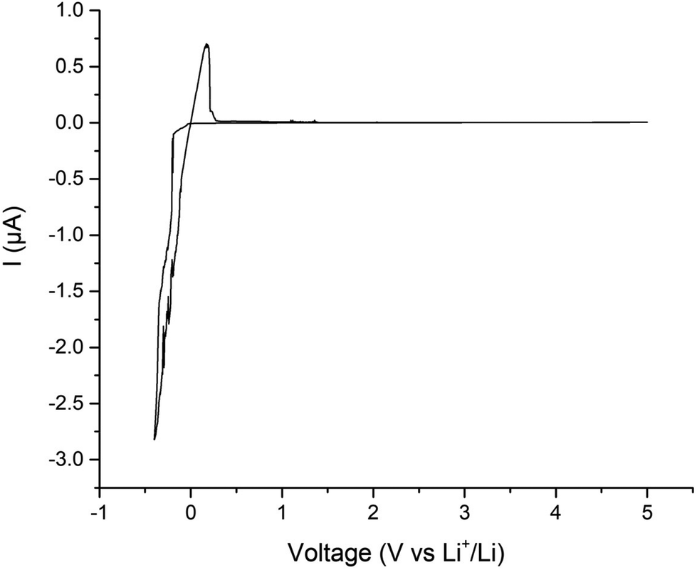 | ||
| Fig. 11 Cyclic voltammetry between −0.4 to 5 V vs. Li+/Li of Ga-NLZO at 1 mV s−1. Small peaks ∼1–1.5 V are attributed to Au/Li alloying. | ||
Cell testing – Li stripping and plating
Li stripping/plating were investigated for the assembled symmetric cells to assess cycling and ASR stability. The cell was left on an open lab bench to approximate real world use, hence small temperature variations were present (between 15–21 °C). The results showed that Ga-NLZO exhibits excellent cycling stability at room temperature at 12.5 and 25 μA cm−2, see Fig. 12. The small fluctuations in the voltage profile relate to the slight alterations in the temperature, with slightly higher voltages occurring overnight and lower voltages during the day. To confirm the voltage stability, a cell was cycled at 50 °C, which shows mostly flat voltage profiles for ∼83 hours. Therefore, no interface degradation is apparent and voltage fluctuations are due to real life temperature variations. However, a large voltage drop is present in Fig. 12 when the current density is increased to 50 μA cm−2, which indicates a short circuit due to dendrite propagation. This dendrite propagation at low current densities suggest that the reaction between Li and the Ga dopant must propagate through the pellet.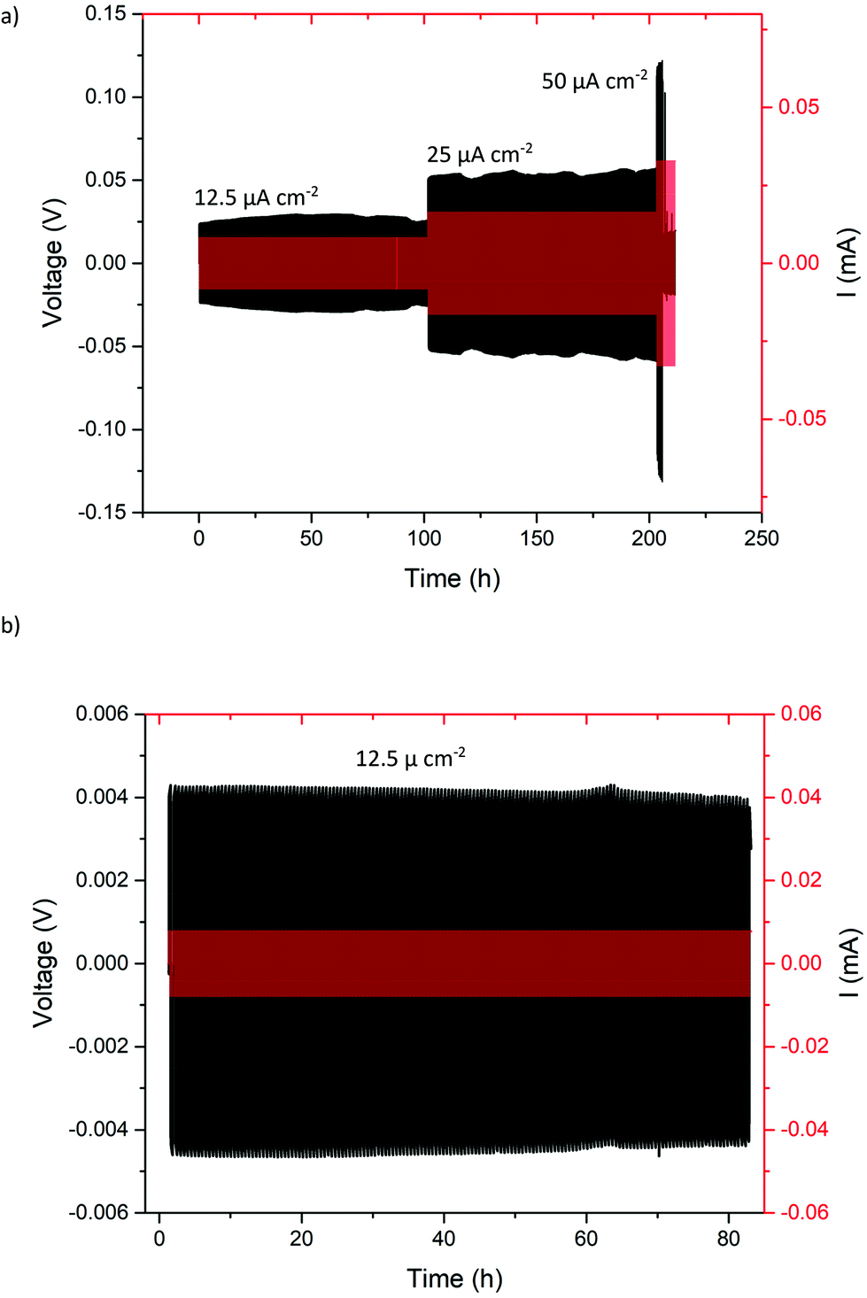 | ||
| Fig. 12 Lithium stripping and plating of Li/Ga-NLZO/Li cell (a) at different current densities at room temperature on open lab bench (between 15–21 °C throughout the day) and (b) at 50 °C to demonstrate flat voltage profile at controlled temperature. | ||
To confirm the short circuit, critical current density (CCD) analysis was conducted on a fresh cell (where CCD is defined as the maximum current which can be applied to a cell before dendritic lithium propagation and short circuiting occurs). CCDs of the lithium garnet systems are thought to depend primarily upon the pellet density (which should be as high as possible), grain boundary characteristics, conductivity, and the ASR (which should be as low as possible).26,31,55,104–106 ASR for this cell was calculated at 95 Ω cm2, pellet density at ∼90% and conductivity in the 0.2 mS cm−1 range. The cell was left on an open lab bench where temperature fluctuated between 20–22 °C. As shown in Fig. 13, the cell follows ohmic current–voltage behaviour up to 50 μA cm−2, at which point a small voltage drop is noted indicative of a short circuit. The short circuit was confirmed by impedance spectroscopy, giving a similar Nyquist plot to Fig. 9. Efforts were made to improve this value by ball milling Ga-NLZO powders for 10 h to improve particle size distribution post sintering. This gave the same CCD value. This is indicative of the processes involved in the low ASR values, which we attribute to the formation of a Ga–Li eutectic at the grain boundary, propagating through the SSE during Li stripping and plating. This, therefore suggests that Ga-NLZO cannot be utilized as an electrolyte on its own with Li metal anodes, but may find use as a CI layer in conjunction with another garnet electrolyte.
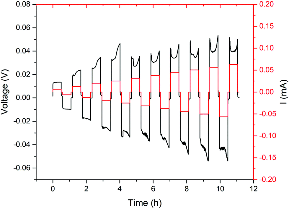 | ||
| Fig. 13 Critical current density analysis, starting at 10 μA cm−2, and increasing in increments of 10 μA cm−2. A small voltage drop is noted at 50 μA cm−2 which corresponded to short circuit. This was confirmed via impedance spectroscopy and was analogous the impedance spectrum found in Fig. 9. | ||
Therefore, a proof-of-concept Li/Ga-NLZO/Ta-LLZCO/Ga-NLZO/Li layered cell was assembled and can be found in Fig. 14. This pellet was prepared and densified via a similar procedure, which resulted in a dense pellet with fused interfaces. The pellet was then analysed via impedance spectroscopy with Au electrodes and assembled into symmetric cells, with the latter demonstrating no mechanical interfacial issues while sanding to a mirror finish, see Fig. 14. All Impedance analysis yielded no additional interface contributions, hence indicating well sintered and connected interfaces. This symmetric cell demonstrated a low ASR value of 102 Ω cm2, similar to Ga-NLZO on its own, with a conductivity at 21 °C of 2.5 × 10⁻⁴ S cm−1. The layered cells showed extended cycling stability, over multiple current densities (up to at least 100 μA cm−2, ∼500 h), significantly beyond the CCD noted solely for the Ga-NLZO garnets. The large voltage drop (indicative of a short circuit) seen for the Ga-NLZO materials in Fig. 12 is absent from the layered cell data, indicating no short circuit over the analysed current densities. Hence Ga-NLZO can be readily co-sintered with other garnets as an interface layer to increase the CCD while maintaining the low ASR values.
 | ||
| Fig. 14 Li/Ga-NLZO/Ta-LLZCO/Ga-NLZO/Li sandwich cells, where (a) is the impedance spectrum of a symmetry cell, fit to three R/CPE parallel components connected in series. Considering the lack of any additional features in the spectrum only three R/CPE components were used, irrespective of the layered structure. Inlay photographs are of the formed pellet, where purple is Ga-NLZO, and white is Ta-LLZCO. (b) is the Li striping and plating stability of the cell at different current densities. The cell was cycled at room temperature on an open lab bench to approximate real world use during summer (15–27 °C), hence fluctuations in the voltage profile. These are more noticeable compared to Fig. 12 due to larger temperature differential, lower voltage troughs occur overnight, whereas high voltage peaks occur in the day. (c) confirms voltage stability when cycled at a fixed temperature (43 °C). | ||
Post cycling analysis
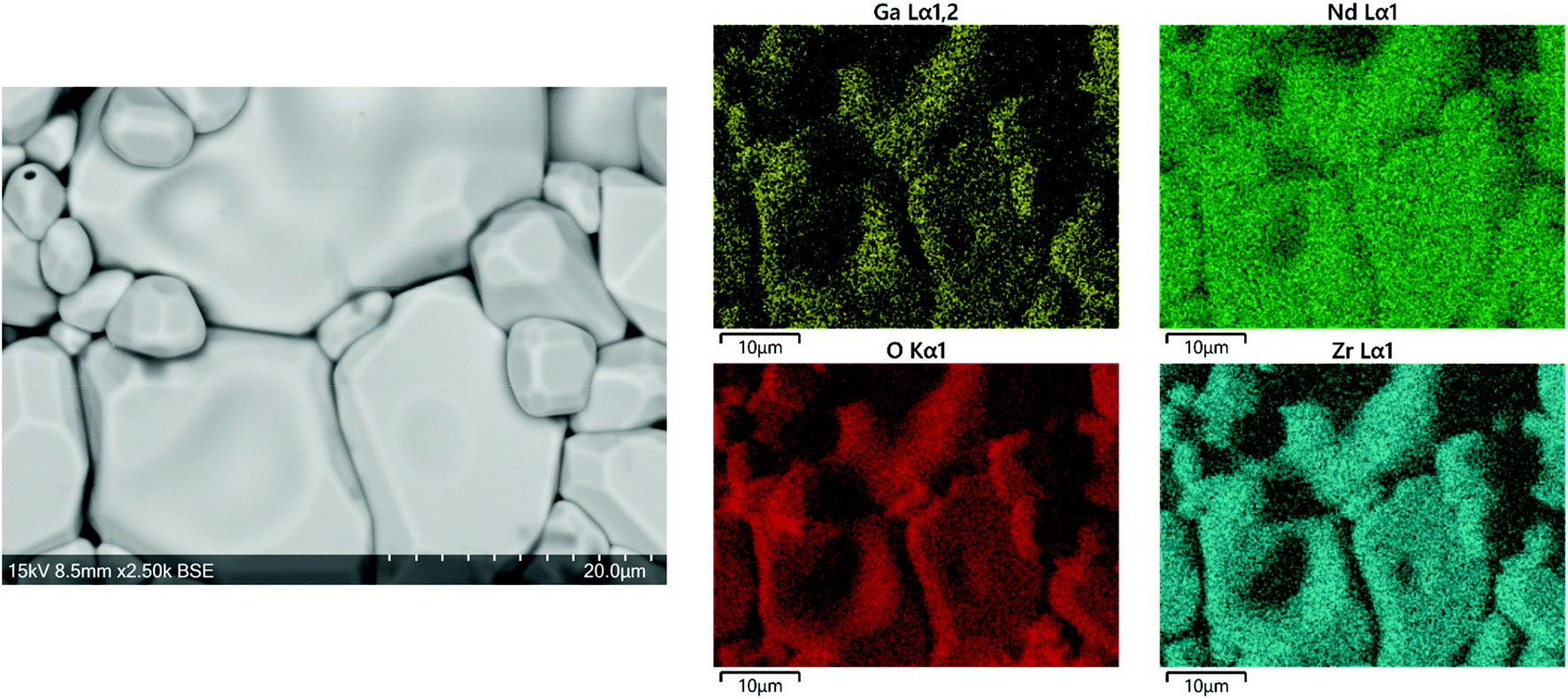
In order to gain more information on the short circuited Ga-NLZO cells, a short-circuited symmetric cell was disassembled, and Li metal removed by melting to reveal the pellet surface, which were subsequently analysed by SEM/EDX and compared with a freshly prepared Ga-NLZO pellet. As the polishing procedure does not yield a surface from which SEM/EDX was able to distinguish any unusual features (see ESI†), the short-circuited pellet was thermally etched via the densification procedure used for fresh Nd garnet pellets, with the aim of also regenerating the pellet. After this heat treatment, individual grains were well resolved (no mother powder was used). The SEM images of the pellet surface revealed unusual elemental clusters, as distinguished from differences in contrast from the BSE image, with grain boundaries showing clear changes in morphology, see Fig. 15. These features were largely present across the entire pellet surface, but were only sparingly present on fresh pellets prior to cycling, and hence they have dramatically increased post Li metal adhesion and cycling. EDX of these clusters revealed accumulations of Zr, encased by Nd surround by Ga plated grain boundaries, see Fig. 15. This yields evidence of Ga exsolution on the pellet surface, which we attribute as contributing to the low CCD by way of Ga–Li eutectic alloys. | ||
| Fig. 15 SEM and EDX images of Ga-NLZO post regeneration, whereby pellet was heated to 1150 °C for 13 hours without protective powder and placed un-polished onto the SEM stub to examine any surface changes compared to Fig. 4. Al signal is thought to arise from Al stub, or perhaps crucible related Al/Li exchange, as this is the same pellet seen in Fig. 3, where no Al signal was detected. | ||
A cross section of the pellet was examined and some areas of altering contrast were seen, particularly in Fig. 16, with EDX demonstrating some corresponding evidence of elemental separation in some areas. This indicates these elemental clusters propagate through the pellet and could be related to the observed low CCD. However, further work is needed to provide confirmation.
 | ||
| Fig. 16 Side SEM images of Ga-NLZO pellet interior after regeneration. Pellet was measured side on after being broken into fragments. Left image shows potential area where dendrite propagated, and right image (and corresponding EDX) shows some elemental separation as in Fig. 15. Al signal is thought to arise from Al stub, or perhaps Al/Li exchange from crucible, as this is the same pellet as in Fig. 3. | ||
As large quantities of these surface impurities were present, the pellet was analysed by XRD which showed that it still appeared to be a mostly pure cubic garnet, see Fig. 17. The pellet surface (pre thermal etching) demonstrated some small background peaks corresponding to Ga–Li eutectics, however these peaks are difficult to resolve due to the weak scattering ability of Li/Ga and will require use of Li sensitive techniques, such as time of flight secondary ion mass spectroscopy, for further confirmation.
 | ||
| Fig. 17 XRD of Ga-NLZO pellet surface from symmetry cell with Li metal removed (prior to thermal etching), and of the pellet powder taken from re-grinding pellet fragment after regenerating the pellet. | ||
To provide some confirmation of our hypothesis concerning Li–Ga eutectic formation through Ga exsolution, we examined the effect of placing Li metal discs in contact with a Ga2O3 pellet and heating to 175 °C (1 h) and also left a Ga2O3 pellet in contact with the metal at room temperature for two days. XRD analysis was subsequently undertaken under inert conditions, with freshly scratched Li metal also analysed for comparison. Both cases indicated a clear reaction with Li metal, with the heated sample fully decomposing Li metal into a black powder. In the heated sample, phases were matched to both Li2Ga and Li–Ga eutectics (see ESI†). Comparing these data to the XRD of the Ga-NLZO pellet surface shows corresponding peaks, hence providing some further evidence of a similar reaction occurring at the Ga-NLZO interface. However, some peaks are overlapping with garnet, whereas others are possibly lost in the background, therefore additional work is required to confirm Ga–Li eutectic formation more absolutely. But, nonetheless, it is clear that Ga-NLZO garnets present with exceptionally low ASR values that are intrinsic to the garnet material, a rare feature.
Finally, the regenerated pellet was sputtered with Au and the conductivity remeasured to assess the recoverability of the Ga-NLZO garnet materials after a short circuit event. As shown in Fig. 18, the pellet was mostly regenerated back to its original properties, demonstrating a comparable conductivity of 0.2 mS cm−1 (20 °C), with the corresponding XRD of the ground powder displayed in Fig. 17.
 | ||
| Fig. 18 Impedance spectrum of regeneration pellet (red) overlaid with a fresh pellet (black), illustrating little change outside a small increase in temperature. | ||
Conclusion
In summary, a range of Nd based Li garnet materials have been synthesised for the first time, with Ga-NLZO in particular having room temperature ionic conductivity (≥2 × 10⁻⁴ S cm−1) similar to La based garnets, despite having significantly smaller lattice parameters. Ga-NLZO also appears relatively straightforward to sinter reproducibly, giving pellets with a high density in lower processing times than equivalent La based garnets. Significantly, we have demonstrated that Ga-NLZO enables very low ASR values in contact with Li metal which remain stable during cell cycling, a feature which is intrinsic to the garnet material itself rather than requiring additional coatings. It is proposed this is due to Ga–Li eutectic formation, which is enhanced by Ga-NLZO due to its much smaller lattice parameters (compared to Ga-LLZO) increasing Ga exsolution when combined with Li metal/heating. Somewhat surprisingly despite the very low ASR value, a comparatively low CCD was observed which requires future work to understand fully, but we propose that it relates to the same Ga exsolution process which enables low ASR values. Despite this issue, the high density and low ASR of Ga-NLZO allows it to be utilized in conjunction with a La based garnet as an interfacial modification to overcome the latter's high Li/electrode interfacial resistance, whereupon Ga-NLZO would act as a CI layer between the Li electrode and the garnet electrolyte.Raw experimental data
https://doi.org/10.25500/edata.bham.00000716.Conflicts of interest
There are no conflicts of interest to declare.Acknowledgements
We would like to thank the University of Birmingham for the studentship funding of Mark Stockham and Matthew James, and the EPSRC for funding the GENESIS project (under EP/R024006/1) and the EPSRC Capital Award for Core Equipment (EP/T02349X/1).Notes and references
- S. Wang, K. Rafiz, J. Liu, Y. Jin and J. Y. S. Lin, Sustainable Energy Fuels, 2020, 4, 2342–2351 RSC.
- B. S. Vishnugopi, F. Hao, A. Verma and P. P. Mukherjee, ACS Appl. Mater. Interfaces, 2020, 12, 23931–23938 CrossRef CAS PubMed.
- M. A. Howard, O. Clemens, K. S. Knight, P. A. Anderson, S. Hafiz, P. M. Panchmatia and P. R. Slater, J. Mater. Chem. A, 2013, 1, 14013–14022 RSC.
- J. M. Tarascon and M. Armand, Nature, 2001, 414, 359 CrossRef CAS PubMed.
- C.-X. Zu and H. Li, Energy Environ. Sci., 2011, 4, 2614–2624 RSC.
- V. A. Agubra and J. W. Fergus, J. Power Sources, 2014, 268, 153–162 CrossRef CAS.
- N. Nitta, F. Wu, J. T. Lee and G. Yushin, Mater. Today, 2015, 18, 252–264 CrossRef CAS.
- M. Winter and R. J. Brodd, Chem. Rev., 2004, 104, 4245–4270 CrossRef CAS PubMed.
- T. Kim, W. Song, D.-Y. Son, L. K. Ono and Y. Qi, J. Mater. Chem. A, 2019, 7, 2942–2964 RSC.
- M. Armand and J. M. Tarascon, Nature, 2008, 451, 652 CrossRef CAS PubMed.
- H. Yang, C. Guo, A. Naveed, J. Lei, J. Yang, Y. Nuli and J. Wang, Energy Storage Mater., 2018, 14, 199–221 CrossRef.
- L. Wang, Z. Zhou, X. Yan, F. Hou, L. Wen, W. Luo, J. Liang and S. X. Dou, Energy Storage Mater., 2018, 14, 22–48 CrossRef.
- H. Wu, D. Zhuo, D. Kong and Y. Cui, Nat. Commun., 2014, 5, 5193 CrossRef CAS PubMed.
- Y. Zhu, X. He and Y. Mo, ACS Appl. Mater. Interfaces, 2015, 7, 23685–23693 CrossRef CAS PubMed.
- J. Li, C. Ma, M. Chi, C. Liang and N. J. Dudney, Adv. Energy Mater., 2015, 5, 1401408 CrossRef.
- H. Liu, X.-B. Cheng, J.-Q. Huang, H. Yuan, Y. Lu, C. Yan, G.-L. Zhu, R. Xu, C.-Z. Zhao, L.-P. Hou, C. He, S. Kaskel and Q. Zhang, ACS Energy Lett., 2020, 5, 833–843 CrossRef CAS.
- B. Dong, J. Yan, B. Walkley, K. K. Inglis, F. Blanc, S. Hull and A. R. West, Solid State Ionics, 2018, 327, 64–70 CrossRef CAS.
- V. Thangadurai, S. Narayanan and D. Pinzaru, Chem. Soc. Rev., 2014, 43, 4714–4727 RSC.
- W. D. Richards, L. J. Miara, Y. Wang, J. C. Kim and G. Ceder, Chem. Mater., 2016, 28, 266–273 CrossRef CAS.
- Y. G. Kim and H. N. G. Wadley, J. Power Sources, 2011, 196, 1371–1377 CrossRef CAS.
- Y. Zhao and L. L. Daemen, Superionic Conductivity in Lithium-Rich Anti-Perovskites, 2012 Search PubMed.
- Y. Zheng, Y. Yao, J. Ou, M. Li, D. Luo, H. Dou, Z. Li, K. Amine, A. Yu and Z. Chen, Chem. Soc. Rev., 2020, 49, 8790–8839 RSC.
- Y. Zhang, F. Chen, R. Tu, Q. Shen and L. Zhang, J. Power Sources, 2014, 268, 960–964 CrossRef CAS.
- M. Botros, R. Djenadic, O. Clemens, M. Möller and H. Hahn, J. Power Sources, 2016, 309, 108–115 CrossRef CAS.
- E. Kazyak, K.-H. Chen, K. N. Wood, A. L. Davis, T. Thompson, A. R. Bielinski, A. J. Sanchez, X. Wang, C. Wang, J. Sakamoto and N. P. Dasgupta, Chem. Mater., 2017, 29, 3785–3792 CrossRef CAS.
- A. Sharafi, H. M. Meyer, J. Nanda, J. Wolfenstine and J. Sakamoto, J. Power Sources, 2016, 302, 135–139 CrossRef CAS.
- L. Cheng, W. Chen, M. Kunz, K. Persson, N. Tamura, G. Chen and M. Doeff, ACS Appl. Mater. Interfaces, 2015, 7, 2073–2081 CrossRef CAS PubMed.
- L. Cheng, C. H. Wu, A. Jarry, W. Chen, Y. Ye, J. Zhu, R. Kostecki, K. Persson, J. Guo, M. Salmeron, G. Chen and M. Doeff, ACS Appl. Mater. Interfaces, 2015, 7, 17649–17655 CrossRef CAS PubMed.
- C. Bernuy-Lopez, W. Manalastas, J. M. Lopez del Amo, A. Aguadero, F. Aguesse and J. A. Kilner, Chem. Mater., 2014, 26, 3610–3617 CrossRef CAS.
- Q. Liu, Z. Geng, C. Han, Y. Fu, S. Li, Y.-b. He, F. Kang and B. Li, J. Power Sources, 2018, 389, 120–134 CrossRef CAS.
- N. J. Taylor, S. Stangeland-Molo, C. G. Haslam, A. Sharafi, T. Thompson, M. Wang, R. Garcia-Mendez and J. Sakamoto, J. Power Sources, 2018, 396, 314–318 CrossRef CAS.
- M. P. Stockham, B. Dong, M. S. James, Y. Li, Y. Ding and P. R. Slater, Dalton Trans., 2021, 50, 2364–2374 RSC.
- Y. Jin and P. J. McGinn, J. Power Sources, 2013, 239, 326–331 CrossRef CAS.
- R. H. Brugge, J. A. Kilner and A. Aguadero, Solid State Ionics, 2019, 337, 154–160 CrossRef CAS.
- H. Duan, H. Zheng, Y. Zhou, B. Xu and H. Liu, Solid State Ionics, 2018, 318, 45–53 CrossRef CAS.
- A. F. Wells, Structural inorganic chemistry, Clarendon Press, 1984 Search PubMed.
- V. Thangadurai, S. Adams and W. Weppner, Chem. Mater., 2004, 16, 2998–3006 CrossRef CAS.
- E. J. Cussen and T. W. S. Yip, J. Solid State Chem., 2007, 180, 1832–1839 CrossRef CAS.
- E. J. Cussen, Chem. Commun., 2006, 412–413, 10.1039/B514640B.
- M. P. O'Callaghan, D. R. Lynham, E. J. Cussen and G. Z. Chen, Chem. Mater., 2006, 18, 4681–4689 CrossRef.
- V. Thangadurai, H. Kaack and W. J. F. Weppner, J. Am. Ceram. Soc., 2004, 86, 437–440 CrossRef.
- R. Murugan, V. Thangadurai and W. Weppner, Angew. Chem., Int. Ed., 2007, 46, 7778–7781 CrossRef CAS PubMed.
- C. A. Geiger, E. Alekseev, B. Lazic, M. Fisch, T. Armbruster, R. Langner, M. Fechtelkord, N. Kim, T. Pettke and W. Weppner, Inorg. Chem., 2011, 50, 1089–1097 CrossRef CAS PubMed.
- J. Awaka, N. Kijima, K. Kataoka, H. Hayakawa, K.-i. Ohshima and J. Akimoto, J. Solid State Chem., 2010, 183, 180–185 CrossRef CAS.
- J. Awaka, N. Kijima, H. Hayakawa and J. Akimoto, J. Solid State Chem., 2009, 182, 2046–2052 CrossRef CAS.
- J. Percival, E. Kendrick, R. I. Smith and P. R. Slater, Dalton Trans., 2009, 5177–5181, 10.1039/b907331k.
- B. Dong, S. R. Yeandel, P. Goddard and P. R. Slater, Chem. Mater., 2020, 32, 215–223 CrossRef CAS.
- R. Wagner, G. J. Redhammer, D. Rettenwander, A. Senyshyn, W. Schmidt, M. Wilkening and G. Amthauer, Chem. Mater., 2016, 28, 1861–1871 CrossRef CAS PubMed.
- J. Percival and P. R. Slater, Solid State Commun., 2007, 142, 355–357 CrossRef CAS.
- R. Murugan, V. Thangadurai and W. Weppner, Appl. Phys. A, 2008, 91, 615–620 CrossRef CAS.
- M. A. Howard, O. Clemens, E. Kendrick, K. S. Knight, D. C. Apperley, P. A. Anderson and P. R. Slater, Dalton Trans., 2012, 41, 12048–12053 RSC.
- J. L. Allen, J. Wolfenstine, E. Rangasamy and J. Sakamoto, J. Power Sources, 2012, 206, 315–319 CrossRef CAS.
- B. Dong, L. L. Driscoll, M. P. Stockham, E. Kendrick and P. R. Slater, Solid State Ionics, 2020, 350, 115317 CrossRef CAS.
- B. Dong, M. P. Stockham, P. A. Chater and P. R. Slater, Dalton Trans., 2020, 49, 11727–11735 RSC.
- F. M. Pesci, R. H. Brugge, A. K. O. Hekselman, A. Cavallaro, R. J. Chater and A. Aguadero, J. Mater. Chem. A, 2018, 6, 19817–19827 RSC.
- M. A. Howard, O. Clemens, E. Kendrick, K. S. Knight, D. C. Apperley, P. A. Anderson and P. R. Slater, Dalton Trans., 2012, 41, 12048–12053 RSC.
- S. Narayanan and V. Thangadurai, J. Power Sources, 2011, 196, 8085–8090 CrossRef CAS.
- S. Narayanan, F. Ramezanipour and V. Thangadurai, J. Phys. Chem. C, 2012, 116, 20154–20162 CrossRef CAS.
- J.-F. Wu, E.-Y. Chen, Y. Yu, L. Liu, Y. Wu, W. K. Pang, V. K. Peterson and X. Guo, ACS Appl. Mater. Interfaces, 2017, 9, 1542–1552 CrossRef CAS PubMed.
- X. Wang, J. Liu, R. Yin, Y. Xu, Y. Cui, L. Zhao and X. Yu, Mater. Lett., 2018, 231, 43–46 CrossRef CAS.
- J. Gai, E. Zhao, F. Ma, D. Sun, X. Ma, Y. Jin, Q. Wu and Y. Cui, J. Eur. Ceram. Soc., 2018, 38, 1673–1678 CrossRef CAS.
- N. Janani, C. Deviannapoorani, L. Dhivya and R. Murugan, RSC Adv., 2014, 4, 51228–51238 RSC.
- V. Thangadurai and W. Weppner, J. Am. Ceram. Soc., 2005, 88, 411–418 CrossRef CAS.
- L. Robben, E. Merzlyakova, P. Heitjans and T. M. Gesing, Acta Crystallogr., Sect. E, 2016, 72, 287–289 CAS.
- Y. Ren, Y. Shen, Y. Lin and C.-W. Nan, Electrochem. Commun., 2015, 57, 27–30 CrossRef CAS.
- D. Wang, K. Peng, Y. Fu, C. Zhu and Y. Yang, J. Power Sources, 2021, 487, 229421 CrossRef CAS.
- Y. Zhu, J. G. Connell, S. Tepavcevic, P. Zapol, R. Garcia-Mendez, N. J. Taylor, J. Sakamoto, B. J. Ingram, L. A. Curtiss, J. W. Freeland, D. D. Fong and N. M. Markovic, Adv. Energy Mater., 2019, 9, 1803440 CrossRef.
- R. H. Brugge, F. M. Pesci, A. Cavallaro, C. Sole, M. A. Isaacs, G. Kerherve, R. S. Weatherup and A. Aguadero, J. Mater. Chem. A, 2020, 8, 14265–14276 RSC.
- J. Saint, M. Morcrette, D. Larcher and J. M. Tarascon, Solid State Ionics, 2005, 176, 189–197 CrossRef CAS.
- J. Sangster and A. D. Pelton, J. Phase Equilib., 1991, 12, 33–36 CrossRef CAS.
- H. Okamoto, J. Phase Equilib. Diffus., 2006, 27, 200–200 CAS.
- H. Xie, K.-S. Park, J. Song and J. B. Goodenough, Electrochem. Commun., 2012, 19, 135–137 CrossRef CAS.
- M. A. Howard, O. Clemens, A. S. Parvathy, P. A. Anderson and P. R. Slater, J. Alloys Compd., 2016, 670, 78–84 CrossRef CAS.
- B. Toby and R. Dreele, J. Appl. Crystallogr., 2013, 46, 544–549 CrossRef CAS.
- R. H. Brugge, A. K. O. Hekselman, A. Cavallaro, F. M. Pesci, R. J. Chater, J. A. Kilner and A. Aguadero, Chem. Mater., 2018, 30, 3704–3713 CrossRef CAS.
- G. Larraz, A. Orera and M. L. Sanjuán, J. Mater. Chem. A, 2013, 1, 11419–11428 RSC.
- C. Galven, J. Dittmer, E. Suard, F. Le Berre and M.-P. Crosnier-Lopez, Chem. Mater., 2012, 24, 3335–3345 CrossRef CAS.
- J. Percival, D. Apperley and P. R. Slater, Solid State Ionics, 2008, 179, 1693–1696 CrossRef CAS.
- H. Peng, Y. Zhang, L. Li and L. Feng, Solid State Ionics, 2017, 304, 71–74 CrossRef CAS.
- I. P. Roof, M. D. Smith, E. J. Cussen and H.-C. zur Loye, J. Solid State Chem., 2009, 182, 295–300 CrossRef CAS.
- F. M. Pesci, A. Bertei, R. H. Brugge, S. P. Emge, A. K. O. Hekselman, L. E. Marbella, C. P. Grey and A. Aguadero, ACS Appl. Mater. Interfaces, 2020, 12, 32806–32816 CrossRef CAS PubMed.
- A. Gupta, R. Murugan, M. P. Paranthaman, Z. Bi, C. A. Bridges, M. Nakanishi, A. P. Sokolov, K. S. Han, E. W. Hagaman, H. Xie, C. B. Mullins and J. B. Goodenough, J. Power Sources, 2012, 209, 184–188 CrossRef CAS.
- Y. Wang, P. Yan, J. Xiao, X. Lu, J.-G. Zhang and V. L. Sprenkle, Solid State Ionics, 2016, 294, 108–115 CrossRef CAS.
- M. P. Stockham, B. Dong, Y. Ding, Y. Li and P. R. Slater, Dalton Trans., 2020, 49, 10349–10359 RSC.
- S. Song, B. Chen, Y. Ruan, J. Sun, L. Yu, Y. Wang and J. Thokchom, Electrochim. Acta, 2018, 270, 501–508 CrossRef CAS.
- M. P. Stockham, B. Dong, Y. Ding, Y. Li and P. R. Slater, Dalton Trans., 2020, 49, 10349–10359 RSC.
- G. V. Alexander, S. Patra, S. V. Sobhan Raj, M. K. Sugumar, M. M. Ud Din and R. Murugan, J. Power Sources, 2018, 396, 764–773 CrossRef CAS.
- C.-L. Tsai, V. Roddatis, C. V. Chandran, Q. Ma, S. Uhlenbruck, M. Bram, P. Heitjans and O. Guillon, ACS Appl. Mater. Interfaces, 2016, 8, 10617–10626 CrossRef CAS PubMed.
- N. C. Rosero-Navarro, R. Kajiura, R. Jalem, Y. Tateyama, A. Miura and K. Tadanaga, ACS Appl. Energy Mater., 2020, 3, 5533–5541 CrossRef CAS.
- B. Liu, Y. Gong, K. Fu, X. Han, Y. Yao, G. Pastel, C. Yang, H. Xie, E. D. Wachsman and L. Hu, ACS Appl. Mater. Interfaces, 2017, 9, 18809–18815 CrossRef CAS PubMed.
- W. Zhou, Y. Zhu, N. Grundish, X. Sen, S. Wang, Y. You, N. Wu, J. Gao, Z. Cui, Y. Li and J. B. Goodenough, Nano Energy, 2018, 53, 926–931 CrossRef CAS.
- B. Xu, W. Li, H. Duan, H. Wang, Y. Guo, H. Li and H. Liu, J. Power Sources, 2017, 354, 68–73 CrossRef CAS.
- A. Sharafi, E. Kazyak, A. L. Davis, S. Yu, T. Thompson, D. J. Siegel, N. P. Dasgupta and J. Sakamoto, Chem. Mater., 2017, 29, 7961–7968 CrossRef CAS.
- Y. Shao, H. Wang, Z. Gong, D. Wang, B. Zheng, J. Zhu, Y. Lu, Y.-S. Hu, X. Guo, H. Li, X. Huang, Y. Yang, C.-W. Nan and L. Chen, ACS Energy Lett., 2018, 3, 1212–1218 CrossRef CAS.
- W. Luo, Y. Gong, Y. Zhu, K. K. Fu, J. Dai, S. D. Lacey, C. Wang, B. Liu, X. Han, Y. Mo, E. D. Wachsman and L. Hu, J. Am. Chem. Soc., 2016, 138, 12258–12262 CrossRef CAS PubMed.
- W. Luo, Y. Gong, Y. Zhu, Y. Li, Y. Yao, Y. Zhang, K. Fu, G. Pastel, C.-F. Lin, Y. Mo, E. D. Wachsman and L. Hu, Adv. Mater., 2017, 29, 1606042 CrossRef PubMed.
- K. Fu, Y. Gong, B. Liu, Y. Zhu, S. Xu, Y. Yao, W. Luo, C. Wang, S. D. Lacey, J. Dai, Y. Chen, Y. Mo, E. Wachsman and L. Hu, Sci. Adv., 2017, 3, e1601659 CrossRef PubMed.
- R. Sudo, Y. Nakata, K. Ishiguro, M. Matsui, A. Hirano, Y. Takeda, O. Yamamoto and N. Imanishi, Solid State Ionics, 2014, 262, 151–154 CrossRef CAS.
- C. Wang, Y. Gong, B. Liu, K. Fu, Y. Yao, E. Hitz, Y. Li, J. Dai, S. Xu, W. Luo, E. D. Wachsman and L. Hu, Nano Lett., 2017, 17, 565–571 CrossRef CAS PubMed.
- W. Feng, X. Dong, P. Li, Y. Wang and Y. Xia, J. Power Sources, 2019, 419, 91–98 CrossRef CAS.
- M. He, Z. Cui, C. Chen, Y. Li and X. Guo, J. Mater. Chem. A, 2018, 6, 11463–11470 RSC.
- J.-F. Wu, B.-W. Pu, D. Wang, S.-Q. Shi, N. Zhao, X. Guo and X. Guo, ACS Appl. Mater. Interfaces, 2019, 11, 898–905 CrossRef CAS PubMed.
- Y. Li, X. Chen, A. Dolocan, Z. Cui, S. Xin, L. Xue, H. Xu, K. Park and J. B. Goodenough, J. Am. Chem. Soc., 2018, 140, 6448–6455 CrossRef CAS PubMed.
- F. Flatscher, M. Philipp, S. Ganschow, H. M. R. Wilkening and D. Rettenwander, J. Mater. Chem. A, 2020, 8, 15782–15788 RSC.
- R. Hongahally Basappa, T. Ito, T. Morimura, R. Bekarevich, K. Mitsuishi and H. Yamada, J. Power Sources, 2017, 363, 145–152 CrossRef CAS.
- X. Huang, Y. Lu, H. Guo, Z. Song, T. Xiu, M. E. Badding and Z. Wen, ACS Appl. Energy Mater., 2018, 1, 5355–5365 CrossRef CAS.
Footnote |
| † Electronic supplementary information (ESI) available. See DOI: 10.1039/d1dt02474d |
| This journal is © The Royal Society of Chemistry 2021 |