 Open Access Article
Creative Commons Attribution 3.0 Unported Licence
Water based synthesis of highly conductive GaxLi7−3xLa3Hf2O12 garnets with comparable critical current density to analogous GaxLi7−3xLa3Zr2O12 systems†
M. P.
Stockham
 *a,
B.
Dong
a,
M. S.
James
a,
Y.
Li
b,
Y.
Ding
b and
P. R.
Slater
 *a
*a
aSchool of Chemistry, University of Birmingham, Birmingham B15 2TT, UK. E-mail: p.r.slater@bham.ac.uk
bSchool of Chemical Engineering, University of Birmingham, Birmingham B15 2TT, UK
First published on 16th December 2020
Abstract
Next generation lithium ion batteries are envisaged as those which feature an all solid-state architecture. This will enable the higher energy density storage required to meet the demands of modern society, especially for the growing electric vehicle market. Solid state batteries have, however, proved troublesome to implement commercially due to the lack of a suitable solid-state electrolyte, which needs to be highly conductive, have a low interfacial resistance and a suitably wide electrochemical stability window. Garnet materials are potential contenders for these batteries, demonstrating many of the desired properties, although there remain challenges to overcome. Here we report a facile synthesis of Li7La3Hf2O12 and Ga/AlxLi7−3xLa3Hf2O12 garnets, with the synthesis of Ga0.2Li6.4La3Hf2O12 requiring only dissolution of precursors in water and heating to 700 °C. Ga0.2Li6.4La3Hf2O12 was shown to display a high room temperature conductivity (0.373 mS cm−1 at 28 °C). Moreover, in Li|garnet|Li cells, we observed a comparable critical current density compared to Ga0.2Lai6.4La3Zr2O12, despite a lower density and higher area specific resistance compared to literature values, suggesting Hf systems may be further engineered to deliver additional improvements for use in future solid state batteries.
Introduction
High energy density secondary lithium ion batteries (LIB) with lithium metal anodes remain the goal of LIB based energy storage research. Li metal has the highest theoretical capacity (3860 mA h g−1) and the lowest electrochemical potential (−3.04 V vs. the standard hydrogen electrode) of all possible anode materials.1,2 However, modern day LIBs use liquid-based electrolytes that enable propagation of lithium dendrites, and so pose significant safety concerns with the use of a Li metal anode.3 Despite intensive research to prevent dendritic growth,4–10 a practical solution to eliminate this issue remains elusive. Furthermore, these electrolytes are flammable, toxic, non-renewable and often have a limited electrochemical window (preventing use of high V cathode materials), hence they are not ideal for the high energy demands of modern-day society.2,11–14Overcoming these issues in LIBs can potentially be solved by new battery architectures which negate the need of a liquid electrolyte, such as an all solid-state battery (ASSB). The solid-state electrolyte (SSE) in such batteries in theory should block dendrite growth, and can be non-flammable and non-toxic. Therefore ASSBs are often described as the next major leap in LIB based energy storage.15
There have been numerous reports of solid state electrolytes showing Li ion conductivity. However, many of these potential LIB electrolytes, such as LISICON, LiPON and sulphides/glass, are limited by either low ionic conductivity or poor electrochemical stability.16–19 Of these materials, the lithium garnet type systems have good conductivity (0.1–1 mS cm−1) to approach conventional LIB electrolytes and also have a wide electrochemical stability window. However, these materials do suffer from poor interfacial contact at the solid–solid interface and an issue of dendritic growth along the grain boundaries between particles.17,20–26 Hence, although garnet materials are promising SSEs for ASSBs, more work is required before they find a practical use as an energy storage system.
A traditional garnet material has the general formula A3B2X3O12 (e.g. A = Mg, Fe, B = Al, Cr, Fe, and X = Si, Fe, Al, Ga).17,27–29 Replacement of the X site with Li yields a lithium garnet system such as Li3Ln3W2O12, with lithium fully occupying the tetrahedral (24d) site. Further modification by changing the A, B cations, e.g. La (A) and Nb, Zr, Hf (B), enables increased lithium content to maintain charge neutrality, with partial lithium occupation of the octahedral interstitial sites 96h and 48g.30,31 Garnets with <7 lithium atoms per formula unit (pfu) can be indexed on a cubic cell with space group Ia![[3 with combining macron]](https://www.rsc.org/images/entities/char_0033_0304.gif) d (no. 230) or in the case of GaxLi7−3xLa3Zr2O12 with <3 La pfu, potentially, I
d (no. 230) or in the case of GaxLi7−3xLa3Zr2O12 with <3 La pfu, potentially, I![[4 with combining macron]](https://www.rsc.org/images/entities/char_0034_0304.gif) 3d.32–34 When the lithium content is increased to 7 atoms pfu, the upper limit, lithium ordering occurs with full occupancy of the octahedral and tetrahedral sites. This cation ordering is necessary to prevent short Li–Li distances and it leads to a reduction of the symmetry from a cubic to a tetragonal cell (I41/acd, no. 142), which reduces conductivity by two orders of magnitude, as the migration mechanism is based upon the need for vacant interstitial sites.
3d.32–34 When the lithium content is increased to 7 atoms pfu, the upper limit, lithium ordering occurs with full occupancy of the octahedral and tetrahedral sites. This cation ordering is necessary to prevent short Li–Li distances and it leads to a reduction of the symmetry from a cubic to a tetragonal cell (I41/acd, no. 142), which reduces conductivity by two orders of magnitude, as the migration mechanism is based upon the need for vacant interstitial sites.
For cubic garnets, such as Li6.4Ga0.2La3Zr2O12, ionic migration pathways have been attributed to two tetrahedral sites bridged by a single face sharing octahedron. As lithium partially occupies the interstitial sites, this gives a disordered Li sublattice and a migration pathway which affords ionic conductivity via the Li+ charge carrier, which is thought to follow the hopping mechanism of 24 d → 96 h → 48 g → 96 h → 24 d, as determined by high temperature neutron diffraction and high resolution nuclear magnetic resonance,35,36 albeit some debate persists as to the exact hopping path.
While highly conducting lithium garnet materials have now been known for some time,37 current synthesis routes for these highly conducting garnets (ionic conductivity >0.1 mS cm−1) are time consuming, energy demanding and require complex procedures, such as field assisted sintering, to enable high enough densities to give high conductivities, as is the situation for the most conductive system Ga0.15Li6.55La3Zr2O12 (Ga0.15-LLZO).20,38,39 Hence a need arises to find a more suitable synthesis strategy for industrialisation which reduces the synthesis and sintering temperature. This will reduce the production costs, and will also help prevent Li+/Al3+ exchange from alumina crucibles, which can be detrimental to conductivity if not correctly controlled.40
Critical current density (CCD), defined as the current density at which lithium dendrites form and short circuit a cell, is another major concern for solid state batteries. High CCDs are dependent on a SSE achieving a high enough density to resist dendrite formation as well as a low area specific resistance (ASR) at the garnet/Li interface. It has been shown that garnet systems such as Ga0.15-LLZO form dendrites at current densities as low as ∼0.16 mA cm−2 (∼95% relative density, ASR of 16.7 Ω cm2).21 CCD can be increased to 2.8 mA cm−2 when employing single crystal Ga0.2-LLZO with an ASR of 13 Ω cm2, but this was demonstrated to be the natural CCD limit for Ga0.2-LLZO, and unfortunately it is impractical to form single crystal garnets on a large scale to be employed in solid state batteries.41
CCDs have been further improved with a variety of additional interlayers, high pressures and in mixed SSE systems.42,43 However, investigations of other systems are required which have increased CCDs intrinsic to their natural form. Of the garnet systems, much attention has been paid to the Li7−3xMxLa3Zr2O12 (M = Al/Ga), however less so to the Hf analogue. This is despite computational studies that indicate Hf based garnets may have increased electrochemical stability over LLZO garnets, while also having been experimentally shown to have increased stability with respect to carbon-related decomposition during battery charging.44–46
Herein we report the first synthesis of cubic Li6.4Ga0.2La3Hf2O12 (Ga-LLHO) an attractive alternative to Ga-LLZO. Ga-LLHO is shown to be not only highly conductive but can be synthesised at only 700 °C. Additionally, an investigation into the electrochemical properties of Ga-LLHO is reported with respect to CCD and cycling stability, both of which show promising results in comparison to Ga-LLZO. Conventional SSE densification processes were used with the results demonstrating a total conductivity of 1.04 mS cm−1 at 63 °C. The synthesis of tetragonal Li7La3Hf2O12 (t-LLHO) and Al0.28-LLHO (Al-LLHO) is also reported by the same method, however the conductivity is lower and higher temperatures and increased dopant ratios are required to form the cubic Al-LLHO phase.
Methods
Stoichiometric quantities of La(NO3)3, Cl2HfO·8H2O, Ga(NO3)3·8H2O, Al(NO3)3·9H2O and LiNO3 were added to ∼10 ml of distilled water separately, waiting for each to dissolve before the next powder was added. A 10% mol excess of Li was added to account for lithium volatility. Ga(NO3)3·8H2O was assumed octahydrate as based on work here.47 The water was heated to 80 °C and constantly stirred. After approximately 1 h of stirring, the stirrer bar was removed, and the solution (total volume ∼10 ml) heated to 350 °C for 1 hour (0.5 °C min−1) in a fume hood to remove the nitrate content. The product was stored ∼100 °C to prevent the atmospheric moisture absorption which occurs once the nitrates are removed; if not stored in this manner the white powder will form a paste like material within 10 min. The product was ground rapidly (to avoid cooling) and placed in a preheated furnace at 100 °C and heated to 700 °C for 12 hours (5 °C min−1). The product was subsequently ball milled (500 rpm, 1 hour, 10 mm ZrO2 balls) with a further 15–20 wt% Li excess and reheated to 700 °C–950 °C. This yielded phase pure t-LLHO, Ga0.2Li6.4La3Hf2O12 (Ga-LLHO) and Al0.28Li6.16La3Hf2O12 (Al-LLHO). Lower Ga contents, e.g. Ga0.15Li6.55La3Hf2O12 (Ga0.15-LLHO), were shown not to lead to formation of the desired pure cubic phase, but rather a mixed cubic/tetragonal system with impurities (see ESI†).Characterisation
All samples were stored in an argon glove box to prevent proton-Li exchange in the garnet.48 Scanning electron microscopy (SEM) was performed on a Hitachi TM4000plus instrument, with the elemental distribution confirmed by the corresponding AZtecOne energy dispersive X-ray (EDX) attachment. Samples were prepared by applying the powders to a carbon tape and analysed at 15 kV in backscattered electron mode. Pellets were also examined in this manner, which were polished with silicon carbide sandpaper from 800 to 4000 grit to form a flat surface. Elemental composition was also analysed via XRF (Bruker Tiger XRF X8), where powders/pellets were placed on mylar film, in a plastic XRF sample cup and examined under He atmosphere. Phase analysis was performed by X-ray diffraction (XRD) using a Bruker D8 diffractometer with Cu source. Experimental pellet densities were determined and compared to theoretical values from Rietveld refinement results (performed using GSAS II software49).Impedance spectroscopy
Samples for Electrochemical impedance spectroscopy (EIS) were prepared as follows: approx. 10 mm diameter pellets were pressed to ca. 3 tonnes and, subsequently, heated to 1100 °C for 12 hours under dry N2 or O2 (1.6 °C min−1). In both cases sacrificial powders were used to protect pellets from Al contamination via the Al2O3 crucible and to prevent Li loss (pellets were thermally etched in a similar manner for SEM images). After sintering, the pellets were polished, painted with gold electrodes and heated to 800 °C for 1 hour in air to cure the Au paste. The pellets were then air quenched to room temperature from >700 °C (to limit H/Li exchange).34,50 A.C. impedance measurements were taken from 5 Hz to 13 MHz using a Hewlett Packard 4192A LF instrument with a 100 mV applied potential from 50–250 °C. Room temperature impedance data were evaluated with a Solartron 1260 impedance analyser from 1 Hz to 10 MHz with a 100 mV potential.Cell assembly
All cell tests were performed on biologic VMP3 and SP50 instruments. Li|Ga-LLHO|Li symmetric cells were assembled in an Ar glove box. Firstly, the pellets (∼1 mm thickness) were polished using silicon carbide sandpaper from 800 to 4000 grit, then lithium metal foil was applied to each side of the pellet. The cell was then heated to 175 °C under a constant pressure for 1 h and secured within a Swagelok cell. Cells were examined via impedance spectroscopy before (and after) cell testing from 10 MHz to 0.1 Hz with a 10 mV potential on a Solartron 1260 impedance analyser. These symmetric cells were then cycled under constant current conditions at various current densities to assess cycling stability at room temperature on an open lab bench (between 10–20 °C throughout the day) and at a constant temperature (60 °C). Cells were also cycled with increasing current density, in increments of 10 μA cm−2, until a short circuit formed to assess CCD at room temperature on an open lab bench.Au|Ga-LLHO|Li cells, for cyclic voltammetry (C.V.), were formed by polishing a Ga-LLHO pellet as above and hand pressing the pellet into Li foil in an Ar glovebox. The cell was placed in a Swagelok cell with Au foil as the working electrode. Cyclic voltammetry was subsequently run from −0.4 to 5 V at a scan rate of 1 mV s−1.
Results and discussion
X-Ray diffraction results
The powder XRD patterns of t-LLHO, Ga-LLHO, and Al-LLHO are shown in Fig. 1. All patterns could be indexed on a tetragonal (I41/acd) and cubic (Ia![[3 with combining macron]](https://www.rsc.org/images/entities/char_0033_0304.gif) d) garnet cell for t-LLHO and Al/Ga-LLHO respectively. After dissolution of the precursors and completion of the first 700° C heating cycle, a small La2O3 impurity was present in addition to an unknown phase, these were overcome by addition of a 15–20 wt% Li excess and a further 700 °C heating cycle. This yielded phase pure t-LLHO and Ga-LLHO. Al-LLHO was prepared similarly, but a higher temperature, further Li excess and increased dopant ratios were needed after the 700 °C stage (950 °C, 14 h) to form the cubic phase, see Table 1. This suggests increased favourability for the formation of the Ga-LLHO and t-LLHO systems in comparison to Al-LLHO. See ESI† for XRD data at different temperatures.
d) garnet cell for t-LLHO and Al/Ga-LLHO respectively. After dissolution of the precursors and completion of the first 700° C heating cycle, a small La2O3 impurity was present in addition to an unknown phase, these were overcome by addition of a 15–20 wt% Li excess and a further 700 °C heating cycle. This yielded phase pure t-LLHO and Ga-LLHO. Al-LLHO was prepared similarly, but a higher temperature, further Li excess and increased dopant ratios were needed after the 700 °C stage (950 °C, 14 h) to form the cubic phase, see Table 1. This suggests increased favourability for the formation of the Ga-LLHO and t-LLHO systems in comparison to Al-LLHO. See ESI† for XRD data at different temperatures.
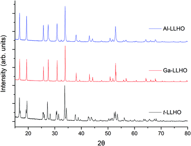 | ||
| Fig. 1 Powder XRD patterns of Al0.28Li6.16La3Hf2O12, Ga0.2Li6.4La3Hf2O12 and Li7La3Hf2O12 synthesised by the dissolution method at 700 °C (Ga-LLHO and LLHO) and 950 °C (Al-LLHO). | ||
| Samples | Quantity of dopant | Lattice parameters (a) (Å) | Lattice parameters (c) (Å) | ρ rel (%) |
|---|---|---|---|---|
| t-LLHO (Lit)51 | — | 13.1056 | 12.6303 | — |
| t-LLHO | — | 13.1097(13) | 12.6513(11) | 60 |
| Ga-LLHO | 0.2 | 12.9663(2) | 87 | |
| Al-LLHO | 0.28 | 12.9820(1) | 88 |
The phase pure XRD patterns of t-LLHO, see Fig. 1, demonstrated peak splitting consistent with the expected reduction in symmetry from a cubic cell to a tetragonal cell. The lattice parameters obtained via Rietveld refinements correspond well to the structural model by Awaka et al.,51 see Table 1. The c/a cell ratio of t-LLHO is c/a = 0.9650, which is similar to the ratio of tetragonal LLZO (0.9641).52
While the facile synthesis of undoped tetragonal LLHO and Ga doped cubic LLHO were readily achieved, synthesis of the corresponding Al doped LLHO proved more challenging, requiring reheating numerous times to higher temperatures (950 °C). For Al-LLHO, Al0.28 pfu was required but this still demonstrated broad peaks likely masking a tetragonal component, see ESI† for details on synthesis steps of this phase.
Ga-LLHO has not been investigated prior, hence reference data are not available, however the pattern corresponds well to the cubic doped LLHO patterns reported by Baklanova46 (Al doped) and Hamao53 (Ta doped). From past work on the analogous Ga-LLZO garnets, two possible cubic space groups have been proposed, with reports that this phase may potentially crystallise with the acentric cubic space group I![[4 with combining macron]](https://www.rsc.org/images/entities/char_0034_0304.gif) 3d rather than Ia
3d rather than Ia![[3 with combining macron]](https://www.rsc.org/images/entities/char_0033_0304.gif) d.32,33 As the XRD patterns do not demonstrate any additional peaks which correspond to the I
d.32,33 As the XRD patterns do not demonstrate any additional peaks which correspond to the I![[4 with combining macron]](https://www.rsc.org/images/entities/char_0034_0304.gif) 3d space group it is assumed the Ga-LLHO garnets possess Ia
3d space group it is assumed the Ga-LLHO garnets possess Ia![[3 with combining macron]](https://www.rsc.org/images/entities/char_0033_0304.gif) d type symmetry, although more detailed neutron diffraction studies would be required to add further confirmation. Attempts to lower the Ga content and so prepare Ga0.15-LLHO were also performed, however this did not yield a pure garnet at any temperature, see ESI,† and so Ga0.2-LLHO appears to be the lowest Ga content to stabilise the cubic garnet phase.
d type symmetry, although more detailed neutron diffraction studies would be required to add further confirmation. Attempts to lower the Ga content and so prepare Ga0.15-LLHO were also performed, however this did not yield a pure garnet at any temperature, see ESI,† and so Ga0.2-LLHO appears to be the lowest Ga content to stabilise the cubic garnet phase.
The dissolution method was also investigated with co-doping Ga (Li site) and Ce (Hf site), Pr (Hf site) and La replacement with Nd, Eu, Gd and Er, with only Nd-LLHO showing some promise, while all others were either impure or did not form the garnet phase (see ESI†). Therefore, it would appear that the Ga-LLHO phase produced via this method is considerably easier to form, with t-LLHO also being formed ∼260 °C below prior reports by Awaka et al.51 for the tetragonal modification. The synthesis conditions for Al-LLHO, although requiring higher temperatures using this method, are still ∼200 °C below previous reports of doped LLHO and with shorter heating times.46,54 Furthermore, this method can also be applied to other garnet systems, with Li7La3Zr2O12 having been successfully made via this route (see ESI†).
XRF, SEM (EDX) results
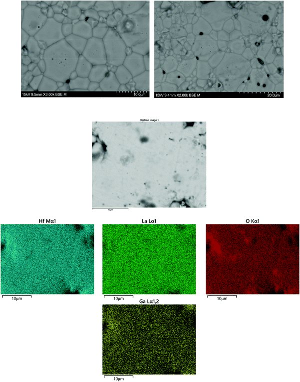
SEM and EDX images of Ga-LLHO synthesised phases are shown in Fig. 2, with SEM/EDX results for other samples found in the ESI.† All phases demonstrate a uniform distribution of elements across all examined grains, indicative of a phase pure sample. In all cases, a small but notable presence of Cl is detected, while other elements are present in expected quantities. No Al emission signals were detected. To further confirm Cl presence and lack of Al contamination, X-ray fluorescence spectroscopy (XRF) was employed. In accordance with the EDX results, in all LLHO phases <1% Cl content was detected by XRF. Furthermore, no Al content was detected by XRF in LLHO or Ga-LLHO, despite no attempt being made to provide protection from the alumina crucible. This is most likely due to the low temperature synthesis preventing the Li+/Al3+ exchange, demonstrating another benefit of this synthesis route. The presence of Cl in the sample can most likely be explained as being from the hafnium oxychloride starting material.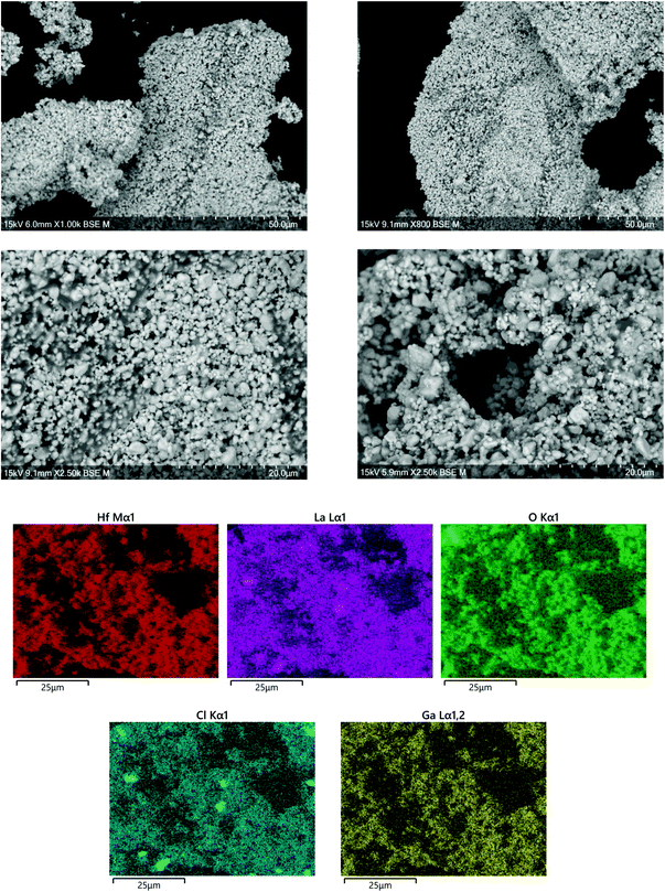 | ||
| Fig. 2 SEM and EDX images of Ga-LLHO, illustrating homogenous distribution of elements throughout the analysed grains, with a presence of Cl detected. Further SEM and EDX data are available in the ESI.† | ||
In order to confirm whether Cl was indeed present in the structure, Cl was added to the oxygen site during Rietveld refinement, and the results suggested a small amount of Cl present after the 700 °C synthesis of t-LLHO. A fractional Cl occupancy of 0.0369 on the 32 g O(1) was present, hence suggesting a Cl content of 0.148 pfu for t-LLHO. The t-LLHO garnets have slightly larger a and c axis dimensions to those reported elsewhere, which is consistent with this small degree of Cl incorporation, see Table 1. Addition of Cl to more than one site did not yield a stable refinement.
Although the addition of Cl to the structure refinements for the Al-LLHO samples gave unstable results, a small amount of Cl was found to be present in Rietveld refinements for the Ga-LLHO phase (Cl occupancy of O site = 0.0163), thus indicating a Cl content of 0.1956 pfu. Further work would be needed to accurately ascertain Cl content and the degree to which this occurs in the structure, as the level of incorporation is uncontrolled during the reaction.
However, analysis via XRF and EDX of garnet pellets after densification under N2 showed Cl was removed, hence Cl incorporation may well be beneficial to formation of the LLHO phases but is unrelated to conductivity or the cell testing data below, see Fig. 3. No Al contamination was detected after pelletisation.
Conductivity measurements
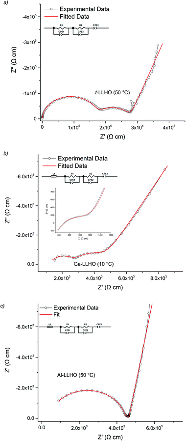
The lithium ion conductivity of the garnets was evaluated via impedance spectroscopy. Nyquist impedance plots for t-LLHO and the dopant phases are shown in Fig. 4. A characteristic spike relative to the semi-circle is present in all plots and is attributed to charging of the electrolyte–electrode interface. This spike represents the Li-ion transfer resistance between the garnet electrolyte and the Au electrode and corresponds to the capacitive behaviour of the gold electrodes which block Li-ion diffusion. The observed semi-circles and tail were obtained in high and low frequency regions respectively, therefore it can be considered that conduction is primarily ionic in nature.55For t-LLHO two semi circles are observed which correspond to bulk and grain boundary contributions, the high intercept of the latter relating to total system conductivity. Al-LLHO has overlapping semi-circles indicating combined bulk and grain boundary contributions. Nyquist plots for t-LLHO and Al-LLHO were fit to two R/CPE parallel components in connected in series, illustrative of bulk and grain boundary resistance, and are similar to those plots for LLZO systems elsewhere.23,42,43,55–60 The Al-LLHO plots demonstrated a small inductive effect, hence an additional inductive component was added. Capacitance values and dielectric constants for the bulk component correspond to values expected for bulk ionic transport within oxide materials,56,59–61 see Table 2. Conductivity values for t-LLHO and Al-LLHO are similar to those reported elsewhere by Awaka et al.51 and Baklanova et al.46 respectively, however the Al-LLHO synthesis reported by the latter group required three heating cycles (900–1200 °C) and over 40 hours to form the material.
| t-LLHO (50 °C) | Ga-LLHO (10 °C) | Al-LLHO (50 °C) | |
|---|---|---|---|
| σ total (S cm−1) | 3.4 × 10⁻⁶ | 1.7 × 10⁻⁴ | 6.6 × 10⁻⁵ |
| σ bulk (S cm−1) | 5.8 × 10⁻⁶ | 3.6 × 10⁻⁴ | 2.2 × 10⁻⁴ |
| C bulk (F cm−1) | 5.08 × 10⁻¹² | 5.99 × 10⁻¹² | 6.18 × 10⁻¹² |
| ε r | 57 | 67 | 70 |
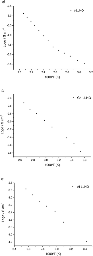
| Activation energy (eV) | 0.52 (50–210 °C) | 0.27 (10–90 °C) | 0.33 (19–117 °C) |
The Ga-LLHO samples showed higher conductivities and the bulk component in the Nyquist plots was largely masked by an inductive effect at room temperature (and above), see Fig. 4b inlay. In order to see the bulk response, the pellet was cooled to 10 °C and in these low temperature data, we can observe bulk and grain boundary contributions, hence the data were fitted with two R/CPE components in parallel.
Ga-LLHO systems demonstrate high total ionic conductivity of 0.382 mS cm−1 at 28 °C, and 1.04 mS cm−1 at 63 °C, which represents an impressive value, especially since the pellet only achieved 87% relative density. The conductivity values are in line with many cubic LLZO (and other garnet) phases and are similar to Ga-LLZO values with higher relative densities.55,56,58,59,62–65 These values therefore represent notably higher conductivities for a doped LLHO garnet compared to the Al, Ta doped samples reported in the literature, while the fact that it has also been synthesised at considerably lower temperature is also significant.46,51,53 An examination into sintering of pellets of Ga-LLHO under O2 at the same temperature led to no difference in relative density or conductivity. Hence N2 or O2 sintering can be employed for these garnets (see ESI†).
Arrhenius plots for t-LLHO, Ga-LLHO and Al-LLHO can be found in Fig. 5 and activation energies in Table 2. The deviation from linearity observed with t-LLHO around 100 °C is attributed to water loss (as a result of some H/Li exchange for this sample) which, despite being quenched from >750 °C and measured, is still present. This can be most likely explained by the fact that for t-LLHO the low conductivity enables even a very low amount of H/Li exchange to give a noticeable change in conductivity.
Cell testing
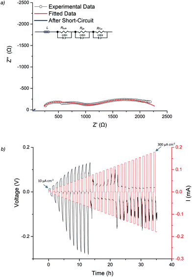
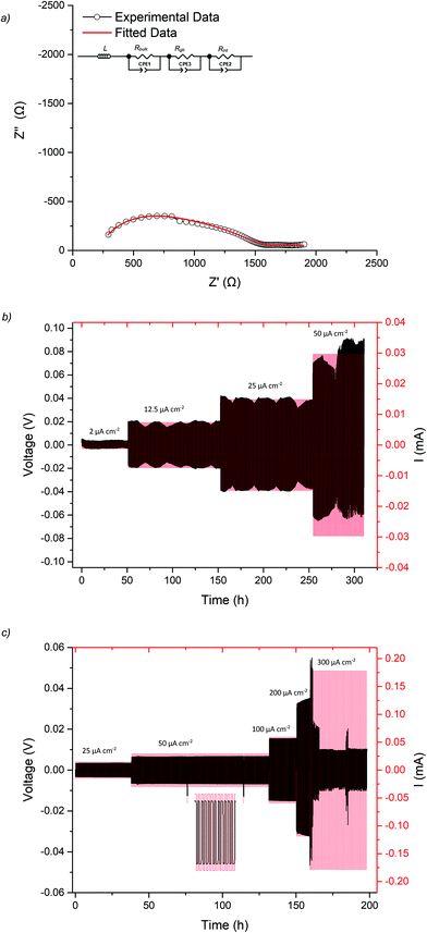
As the Ga-LLHO phase demonstrated the highest conductivity, it represents the most attractive alternative to Ga-LLZO as a potential SSE. Therefore, this Ga-LLHO sample was investigated for cell testing. Li symmetric cells were prepared by hot pressing Li foil onto the pellet surface as described in the experimental section. Impedance spectroscopy was performed prior to cell testing to examine the interfacial resistance properties of the garnet | Li interface after the hot-pressing technique, see Fig. 6a and 7a. The conductivity values obtained from the Nyquist plot for the Ga-LLHO pellet are in agreement with previous results, albeit the values are slightly lower at 0.175 mS cm−1 at 18 °C (compared to 0.270 mS cm−1 at the same temperature for the prior conductivity pellet), despite the slightly higher density for the cell test pellet: ρrel of 90.5%. The slightly lower conductivity values likely arose due to the volatility of lithium during densification; however, the improved sintering has enabled a more well resolved bulk component to be revealed at room temperature. Hence the impedance spectrum was fit with three CPE/R components, representing bulk, grain boundary and Li|garnet interface contributions.CCD was evaluated at room temperature as shown in Fig. 6b. The symmetric cell was cycled at room temperature, on an open lab bench, with increasing current densities from 10 μA cm−2 to 300 μA cm−2. The cell had an ASR value of 464 Ω cm2. The Li|Ga-LLHO|Li symmetric cell demonstrated ohmic current–voltage behaviour up to 120 μA cm−2 with some overpotentials observed above 40 μA cm−2. These overpotentials increase in line with increased current densities until a large voltage drop occurred at 120 μA cm−2, indicating cell short circuit and propagation of Li dendrites, with this confirmed by impedance spectroscopy in Fig. 6a. When the cell is cycled at 60 °C, see Fig. 7c, a voltage drop is noted at 300 μA cm−2 which indicates a higher CCD of the Ga-LLHO cell at 60 °C.
CCDs of the lithium garnet systems are thought to depend primarily upon the density of the pellet (which should be as high as possible), grain boundary characteristics, conductivity and the ASR (which should be as low as possible).21,41,42,66–69 The dependency of CCDs on ASR was systematically evaluated by Flatscher et al. with Ga0.2Li6.4La3Zr2O12 (Ga0.2-LLZO) using single crystals (hence relative density is 100%). As this system is analogous to Ga-LLHO comparisons can be drawn. Flatscher et al. demonstrated that a Ga0.2-LLZO cell with 100% relative density and an ASR of 253 Ω cm2 would form a short circuit at 120 μA cm−2; this is the same CCD observed for the Ga-LLHO cell which has considerably lower density (90.5%), a higher ASR (464 Ω cm2) and decreased conductivity (0.175 mS cm−1vs. 1 mS cm−1).41
Work by Pesci et al. found that with high density (>95%), high conductivity (0.74 mS cm−1) and low ASR (16.7 Ω cm2) pellets of Li6.55Ga0.15La3Zr2O12 had a CCD of 0.16 mA cm−2. This CCD is slightly higher than the reported CCD of Ga-LLHO, but is nonetheless comparable, despite lower Li content, lower density and a much higher ASR.21 Hence the Ga-LLHO system suggests an increased CCD over the Ga-LLZO phase, however more comparative work is needed to confirm. Although the work by Flatscher et al. and Pesci et al. is amongst the most exhaustive when considering Ga-LLZO CCDs, it should also be noted that irrespective of density, ASR and conductivity the CCD values of Ga-LLHO are often higher, or at least very similar, to those reported for Al doped LLZO phases synthesised by conventional methods (e.g. without hot pressing and using alumina crucibles).21,66,70,71 As of yet no CCD studies have been performed on LLHO garnets, hence a direct comparison is not possible. Nevertheless, we propose that these Ga doped LLHO systems offer significant promise if improvements to the sintering and reductions in the interfacial resistance can be made.
To assess cycling and interface stability, a Li|Ga-LLHO|Li symmetry cell was examined under constant current conditions while galvanostatically plating and stripping Li metal. Fig. 7b and c shows the time dependant voltage profile where Li|Ga-LLHO|Li symmetric cells were cycled at room temperature (between 10 and 19 °C) and at 60 °C at various current densities. Positive voltage indicates Li stripping, whereas negative indicates Li plating.72 Cells were cycled for 30 minutes for each charge/discharge cycle for a total of 310 hours at room temperature. The repeating fluctuation in the voltage profile for the room temperature data is ascribed to temperature variations during cell cycling, as the cell was left on an open bench in a non-air-conditioned lab to approximate general temperature alterations found in real world use. This is confirmed as the peaks in voltage occurred overnight, whereas lower voltage troughs occurred in the daytime, corresponding to warmer temperatures and increased conductivity. Cycling stability improves considerably at 60 °C with mostly flat voltage profiles observed when the cell was cycled at the varying current densities (Fig. 7c).
Finally, cyclic voltammetry was performed to assess the electrochemical stability of the Ga-LLHO phase from −0.4 to 5 V, see Fig. 8. As can be seen, clear peaks are present at ∼0.3 V and ∼−0.4 which indicate Li stripping and Li plating respectively. The small peaks on the tail of ∼0.3 V peak are indicative of alloying between Au and Li. Outside of this, the voltage profile remains mostly flat throughout the scan with an absence of clear redox peaks, indicating stability of the Ga-LLHO phase across this range in the presence of Li metal.
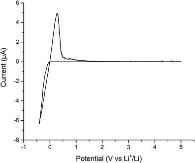 | ||
| Fig. 8 Cyclic voltammetry of Au|Ga-LLHO|Li cell, showing Li stripping and plating peaks at ∼0.3 V and ∼−0.4 V respectively, with peaks at lower potentials indicative of Au/Li alloying. | ||
Conclusion
In this work we have shown a low temperature (700 °C) route to a variety of LLHO garnets which eliminates Al contamination from the alumina crucible. Of particular interest was to illustrate a potential attractive alternative to Ga-LLZO which has garnered significant attention over recent years. In doing so we have found that Ga-LLHO is relatively simple to prepare and it appears that this particular phase is far easier to form than other variations of the LLHO system. Furthermore, a high CCD is demonstrated compared to the comparable Ga0.2-LLZO system, in addition to room temperature stable cycling and excellent cycling stability at 60 °C. We have also demonstrated that Al-LLHO can also be synthesised via this route, albeit at a higher temperature. Furthermore, this synthesis method could likely be applied to a wide range of garnet materials, in particular those which have a dichloride octahydrate precursor.Conflicts of interest
There are no conflicts of interest to declare.Acknowledgements
We would like to thank the University of Birmingham for the studentship funding of Mark Stockham and Matthew James and the EPSRC for funding the GENESIS project (under EP/R024006/1). Raw experimental data can be found at: https://doi.org/10.25500/edata.bham.00000576References
- M. Armand and J. M. Tarascon, Nature, 2008, 451, 652 CrossRef CAS.
- J. M. Tarascon and M. Armand, Nature, 2001, 414, 359 CrossRef CAS.
- Y. Zhu, X. He and Y. Mo, ACS Appl. Mater. Interfaces, 2015, 7, 23685–23693 CrossRef CAS.
- C. Yang, K. Fu, Y. Zhang, E. Hitz and L. Hu, Adv. Mater., 2017, 29, 1701169 CrossRef.
- H. Yang, C. Guo, A. Naveed, J. Lei, J. Yang, Y. Nuli and J. Wang, Energy Storage Mater., 2018, 14, 199–221 CrossRef.
- H. Yuan, J. Nai, H. Tian, Z. Ju, W. Zhang, Y. Liu, X. Tao and X. W. Lou, Sci. Adv., 2020, 6, eaaz3112 CrossRef CAS.
- N.-W. Li, Y.-X. Yin, C.-P. Yang and Y.-G. Guo, Adv. Mater., 2016, 28, 1853–1858 CrossRef CAS.
- L. Wang, Z. Zhou, X. Yan, F. Hou, L. Wen, W. Luo, J. Liang and S. X. Dou, Energy Storage Mater., 2018, 14, 22–48 CrossRef.
- H. Dai, X. Gu, J. Dong, C. Wang, C. Lai and S. Sun, Nat. Commun., 2020, 11, 643 CrossRef CAS.
- S. Liang, Y. Shi, T. Ma, W. Yan, S. Qin, Y. Wang, Y. Zhu, H. Wang and Y. Wu, ChemElectroChem, 2019, 6, 5413–5419 CrossRef CAS.
- C.-X. Zu and H. Li, Energy Environ. Sci., 2011, 4, 2614–2624 RSC.
- V. A. Agubra and J. W. Fergus, J. Power Sources, 2014, 268, 153–162 CrossRef CAS.
- N. Nitta, F. Wu, J. T. Lee and G. Yushin, Mater. Today, 2015, 18, 252–264 CrossRef CAS.
- M. Winter and R. J. Brodd, Chem. Rev., 2004, 104, 4245–4270 CrossRef CAS.
- J. Li, C. Ma, M. Chi, C. Liang and N. J. Dudney, Adv. Energy Mater., 2015, 5, 1401408 CrossRef.
- B. Dong, J. Yan, B. Walkley, K. K. Inglis, F. Blanc, S. Hull and A. R. West, Solid State Ionics, 2018, 327, 64–70 CrossRef CAS.
- V. Thangadurai, S. Narayanan and D. Pinzaru, Chem. Soc. Rev., 2014, 43, 4714–4727 RSC.
- W. D. Richards, L. J. Miara, Y. Wang, J. C. Kim and G. Ceder, Chem. Mater., 2016, 28, 266–273 CrossRef CAS.
- Y. G. Kim and H. N. G. Wadley, J. Power Sources, 2011, 196, 1371–1377 CrossRef CAS.
- C. Bernuy-Lopez, W. Manalastas, J. M. Lopez del Amo, A. Aguadero, F. Aguesse and J. A. Kilner, Chem. Mater., 2014, 26, 3610–3617 CrossRef CAS.
- F. M. Pesci, R. H. Brugge, A. K. O. Hekselman, A. Cavallaro, R. J. Chater and A. Aguadero, J. Mater. Chem. A, 2018, 6, 19817–19827 RSC.
- Q. Liu, Z. Geng, C. Han, Y. Fu, S. Li, Y.-b. He, F. Kang and B. Li, J. Power Sources, 2018, 389, 120–134 CrossRef CAS.
- H. Buschmann, J. Dölle, S. Berendts, A. Kuhn, P. Bottke, M. Wilkening, P. Heitjans, A. Senyshyn, H. Ehrenberg, A. Lotnyk, V. Duppel, L. Kienle and J. Janek, Phys. Chem. Chem. Phys., 2011, 13, 19378–19392 RSC.
- S. Ohta, T. Kobayashi and T. Asaoka, J. Power Sources, 2011, 196, 3342–3345 CrossRef CAS.
- T. Thompson, J. Wolfenstine, J. L. Allen, M. Johannes, A. Huq, I. N. David and J. Sakamoto, J. Mater. Chem. A, 2014, 2, 13431–13436 RSC.
- X. Xiong, Q. Zhou, Y. Zhu, Y. Chen, L. Fu, L. Liu, N. Yu, Y. Wu and T. van Ree, Energy Fuels, 2020, 34, 10503–10512 CrossRef CAS.
- A. F. Wells, Structural inorganic chemistry, Clarendon Press, 1984 Search PubMed.
- E. J. Cussen and T. W. S. Yip, J. Solid State Chem., 2007, 180, 1832–1839 CrossRef CAS.
- D. Mazza, Mater. Lett., 1988, 7, 205–207 CrossRef CAS.
- J. Percival, E. Kendrick, R. I. Smith and P. R. Slater, Dalton Trans., 2009, 5177–5181, 10.1039/b907331k.
- J. Percival and P. R. Slater, Solid State Commun., 2007, 142, 355–357 CrossRef CAS.
- R. Wagner, G. J. Redhammer, D. Rettenwander, A. Senyshyn, W. Schmidt, M. Wilkening and G. Amthauer, Chem. Mater., 2016, 28, 1861–1871 CrossRef CAS.
- L. Robben, E. Merzlyakova, P. Heitjans and T. M. Gesing, Acta Crystallogr., Sect. E, 2016, 72(3), 287–289 CAS.
- J. Percival, D. Apperley and P. Slater, Solid State Ionics, 2008, 179, 1693–1696 CrossRef CAS.
- J. Han, J. Zhu, Y. Li, X. Yu, S. Wang, G. Wu, H. Xie, S. C. Vogel, F. Izumi, K. Momma, Y. Kawamura, Y. Huang, J. B. Goodenough and Y. Zhao, Chem. Commun., 2012, 48, 9840–9842 RSC.
- D. Wang, G. Zhong, W. K. Pang, Z. Guo, Y. Li, M. J. McDonald, R. Fu, J.-X. Mi and Y. Yang, Chem. Mater., 2015, 27, 6650–6659 CrossRef CAS.
- V. Thangadurai, H. Kaack and W. J. F. Weppner, J. Am. Ceram. Soc., 2004, 86, 437–440 CrossRef.
- M. Botros, R. Djenadic, O. Clemens, M. Möller and H. Hahn, J. Power Sources, 2016, 309, 108–115 CrossRef CAS.
- C. Loho, R. Djenadic, M. Bruns, O. Clemens and H. Hahn, J. Electrochem. Soc., 2017, 164, A6131–A6139 CrossRef CAS.
- C. A. Geiger, E. Alekseev, B. Lazic, M. Fisch, T. Armbruster, R. Langner, M. Fechtelkord, N. Kim, T. Pettke and W. Weppner, Inorg. Chem., 2011, 50, 1089–1097 CrossRef CAS.
- F. Flatscher, M. Philipp, S. Ganschow, H. M. R. Wilkening and D. Rettenwander, J. Mater. Chem. A, 2020, 8, 15782–15788 RSC.
- N. J. Taylor, S. Stangeland-Molo, C. G. Haslam, A. Sharafi, T. Thompson, M. Wang, R. Garcia-Mendez and J. Sakamoto, J. Power Sources, 2018, 396, 314–318 CrossRef CAS.
- T. Deng, X. Ji, Y. Zhao, L. Cao, S. Li, S. Hwang, C. Luo, P. Wang, H. Jia, X. Fan, X. Lu, D. Su, X. Sun, C. Wang and J.-G. Zhang, Adv. Mater., 2020, 32, 2000030 CrossRef CAS.
- R. Jalem, Y. Morishita, T. Okajima, H. Takeda, Y. Kondo, M. Nakayama and T. Kasuga, J. Mater. Chem. A, 2016, 4, 14371–14379 RSC.
- A. Gupta, R. Murugan, M. P. Paranthaman, Z. Bi, C. A. Bridges, M. Nakanishi, A. P. Sokolov, K. S. Han, E. W. Hagaman, H. Xie, C. B. Mullins and J. B. Goodenough, J. Power Sources, 2012, 209, 184–188 CrossRef CAS.
- Y. V. Baklanova, A. P. Tyutyunnik, N. V. Tarakina, A. D. Fortes, L. G. Maksimova, D. V. Korona and T. A. Denisova, J. Power Sources, 2018, 391, 26–33 CrossRef CAS.
- V. Berbenni, C. Milanese, G. Bruni and A. Marini, J. Therm. Anal. Calorim., 2005, 82, 401–407 CrossRef CAS.
- J. Percival, D. Apperley and P. R. Slater, Solid State Ionics, 2008, 179, 1693–1696 CrossRef CAS.
- B. Toby and R. Dreele, J. Appl. Crystallogr., 2013, 46, 544–549 CrossRef CAS.
- M. A. Howard, O. Clemens, E. Kendrick, K. S. Knight, D. C. Apperley, P. A. Anderson and P. R. Slater, Dalton Trans., 2012, 41, 12048–12053 RSC.
- J. Awaka, N. Kijima, K. Kataoka, H. Hayakawa, K.-i. Ohshima and J. Akimoto, J. Solid State Chem., 2010, 183, 180–185 CrossRef CAS.
- J. Awaka, N. Kijima, H. Hayakawa and J. Akimoto, J. Solid State Chem., 2009, 182, 2046–2052 CrossRef CAS.
- N. Hamao, K. Kataoka and J. Akimoto, Li-ion conductivity and crystal structure of garnet-type Li6.5La3M1.5Ta0.5O12 (M = Hf, Sn) oxides, 2017 Search PubMed.
- L. Ladenstein, S. Simic, G. Kothleitner, D. Rettenwander and H. M. R. Wilkening, J. Phys. Chem. C, 2020, 124, 16796–16805 CrossRef CAS.
- R. Murugan, V. Thangadurai and W. Weppner, Angew. Chem., Int. Ed., 2007, 46, 7778–7781 CrossRef CAS.
- R. H. Brugge, J. A. Kilner and A. Aguadero, Solid State Ionics, 2019, 337, 154–160 CrossRef CAS.
- S. Song, B. Chen, Y. Ruan, J. Sun, L. Yu, Y. Wang and J. Thokchom, Electrochim. Acta, 2018, 270, 501–508 CrossRef CAS.
- J. L. Allen, J. Wolfenstine, E. Rangasamy and J. Sakamoto, J. Power Sources, 2012, 206, 315–319 CrossRef CAS.
- B. Dong, L. L. Driscoll, M. P. Stockham, E. Kendrick and P. R. Slater, Solid State Ionics, 2020, 350, 115317 CrossRef CAS.
- B. Dong, S. R. Yeandel, P. Goddard and P. R. Slater, Chem. Mater., 2020, 32, 215–223 CrossRef CAS.
- R. H. Brugge, A. K. O. Hekselman, A. Cavallaro, F. M. Pesci, R. J. Chater, J. A. Kilner and A. Aguadero, Chem. Mater., 2018, 30, 3704–3713 CrossRef CAS.
- M. P. Stockham, B. Dong, Y. Ding, Y. Li and P. R. Slater, Dalton Trans., 2020, 49(30), 10349–10359 RSC.
- J. Wolfenstine, J. Ratchford, E. Rangasamy, J. Sakamoto and J. L. Allen, Mater. Chem. Phys., 2012, 134, 571–575 CrossRef CAS.
- D. Rettenwander, G. Redhammer, F. Preishuber-Pflügl, L. Cheng, L. Miara, R. Wagner, A. Welzl, E. Suard, M. M. Doeff, M. Wilkening, J. Fleig and G. Amthauer, Chem. Mater., 2016, 28, 2384–2392 CrossRef CAS.
- B. Dong, M. P. Stockham, P. A. Chater and P. R. Slater, Dalton Trans., 2020, 49, 11727–11735 RSC.
- A. Sharafi, H. M. Meyer, J. Nanda, J. Wolfenstine and J. Sakamoto, J. Power Sources, 2016, 302, 135–139 CrossRef CAS.
- X. Huang, Y. Lu, H. Guo, Z. Song, T. Xiu, M. E. Badding and Z. Wen, ACS Appl. Energy Mater., 2018, 1, 5355–5365 CrossRef CAS.
- R. Hongahally Basappa, T. Ito, T. Morimura, R. Bekarevich, K. Mitsuishi and H. Yamada, J. Power Sources, 2017, 363, 145–152 CrossRef CAS.
- Y. Song, L. Yang, W. Zhao, Z. Wang, Y. Zhao, Z. Wang, Q. Zhao, H. Liu and F. Pan, Adv. Energy Mater., 2019, 9, 1900671 CrossRef.
- L. Cheng, W. Chen, M. Kunz, K. Persson, N. Tamura, G. Chen and M. Doeff, ACS Appl. Mater. Interfaces, 2015, 7, 2073–2081 CrossRef CAS.
- E. J. Cheng, A. Sharafi and J. Sakamoto, Electrochim. Acta, 2017, 223, 85–91 CrossRef CAS.
- K. Fu, Y. Gong, G. T. Hitz, D. W. McOwen, Y. Li, S. Xu, Y. Wen, L. Zhang, C. Wang, G. Pastel, J. Dai, B. Liu, H. Xie, Y. Yao, E. D. Wachsman and L. Hu, Energy Environ. Sci., 2017, 10, 1568–1575 RSC.
Footnote |
| † Electronic supplementary information (ESI) available. See DOI: 10.1039/d0dt03774e |
| This journal is © The Royal Society of Chemistry 2021 |

