
 Open Access Article
 This Open Access Article is licensed under a Creative Commons Attribution-Non Commercial 3.0 Unported Licence
Gamma-radiation induced synthesis of freestanding nickel nanoparticles†
Yi
Yang
 a,
M.
Johansson
a,
A.
Wiorek
a,
N. V.
Tarakina
b,
F.
Sayed
c,
R.
Mathieu
c,
M.
Jonsson
a and
I. L.
Soroka
*a
a,
M.
Johansson
a,
A.
Wiorek
a,
N. V.
Tarakina
b,
F.
Sayed
c,
R.
Mathieu
c,
M.
Jonsson
a and
I. L.
Soroka
*a
aDepartment of Chemistry, School of Engineering Sciences in Chemistry, Biotechnology and Health, KTH Royal Institute of Technology, S-100 44 Stockholm, Sweden. E-mail: soroka@kth.se
bMax-Planck-Institut für Kolloid-und Grenzflächenforschung, 14476 Potsdam, Germany
cDepartment of Materials Sciences and Engineering, Uppsala University, Box 35, SE-751 03, Uppsala, Sweden
First published on 15th December 2020
Abstract
A versatile method to produce metallic nickel nanoparticles is demonstrated. Metallic Ni nanoparticles have been synthesized from aqueous solution of NiCl2 using γ-radiation induced reduction. To prevent Ni re-oxidation, post-irradiation treatment was elaborated. Structural and compositional analyses were executed using X-ray diffraction, transmission electron microscopy and X-ray photoelectron spectroscopy. These studies reveal that the synthesized material consists of fcc Ni particles having size of 3.47 ± 0.71 nm. The nanoparticles have a tendency to agglomerate to the larger clusters. The latter are partially oxidized to form thin amorphous/poor-crystalline Ni(OH)2/NiO layers at the surface. Magnetization measurements demonstrate that the nanomaterial exhibit ferromagnetic-like behaviour with magnetization 30% lower than that in bulk Ni. The large active surface area (ECSA, 39.2 m2 g−1) and good electrochemical reversibility, confirmed by the electrochemical studies, make the synthesized material a potential candidate as an active component for energy storage devices.
Introduction
Ni and Ni-based materials have attracted much attention due to their variable potential applications, such as non-noble catalysts for hydrogen generation1–3 and oxygen reduction reactions (ORR).4,5 Ni can also be used as an absorbent of chemicals, such as sulphates and nitrates, for the waste water treatment6 and has good antimicrobial activity.7 These applications require large surface area and stability towards degradation. Moreover, a green approach with respect to material processing and utilization implies a reduction in the amount of materials used upon an increase of their efficiency. The use of nanostructured materials for which the surface to volume ratio is large and the catalytic efficiency may be enhanced due to quantum effects constitute an important step in this direction.In the last decades, different chemical routes to synthesize free-standing and supported Ni based nanomaterials have been developed. These routes include chemical reduction,8,9 micro-emulsion,10 thermal decomposition11 and sol–gel12 methods. Another possible demonstrated approach to synthesize Ni-based nanomaterials is γ-radiation induced synthesis.13 Nanoparticle synthesis induced by ionizing radiation (high energy electrons, γ- and X-ray photons) has been proven quite versatile in engineering metal- and metal–oxide-based nanomaterials at the laboratory scale.14,15,16–19 Although the method is less common it has some clear advantages: it allows engineering of nanomaterials with uniform size and well defined composition using relatively simple synthesis schemes;20 it is a room temperature process and requires minimal use of potentially harmful chemicals21 and it allows to obtain a final product (for example, supported nanoparticles) in situ and parallel sterilization of the product can be done if required. The use of this method is limited mainly by the availability of a radiation source.
As shown in the literature, nickel oxidize readily even under ambient conditions. When exposed to air, Ni2+, Ni3+ oxide/hydroxide layers tend to form at the metallic Ni surface,22–25 while ultrafine Ni particles may be fully oxidized to form NiO.22 Formation of oxide layers on the surface of Ni either during the synthesis or in the final application should be considered since it influences the properties and may deteriorate the performance of the material.
Several attempts have been made to synthesize metallic Ni by using aqueous radiolysis. Formation of nickel oligomers in solution by pulse radiolysis in the presence of surfactants was reported earlier.26–28 These oligomers were readily oxidized within one day in aqueous solutions exposed to air. Although free-standing Ni nanoparticles, obtained by radiolytic methods appeared to be unstable, those deposited on an oxide or carbon support were rather stable and demonstrated catalytic activity for various reactions.13,29–31
In our previous study31 we made an attempt to produce freestanding nickel nanoparticles from aqueous solution using γ-radiation induced reduction of Ni2+. In this process, a black precipitate was formed. We concluded that the precipitate contains metallic Ni particles since it was attracted by a strong magnet, forming quaint shapes in solution. The size of the obtained particles, as confirmed by TEM, was about 2 nm. However, after a fairly short time in solution exposed to air, the precipitate changed its colour and consistency to a light green jelly-like mass of Ni hydroxide that was not attracted by the magnet any longer. Nickel deposited on carbon black using the same synthesis parameters was shown to possess ferromagnetic properties and increased activity for ORR. Since the amount of Ni on carbon was negligibly small, in ref. 31 we managed to prove the presence of metallic Ni in the samples by an in-direct method, using magnetic measurements (SQUID).
The aim of the current study is to investigate the conditions, which influence the Ni particles formation during γ-radiation-induced synthesis, and elaborate a synthesis route as well as post-irradiation treatment to produce freestanding (unsupported) metallic nickel nanoparticles. In addition, the structural, magnetic and electrochemical properties of the obtained material are studied.
Experimental
Gamma irradiation
Gamma irradiation was performed using a MDS Nordion 1000 Elite Cs-137 gamma source with a dose rate 0.12 Gy s−1.X-ray diffraction
X-ray diffraction measurements were carried out using a PANalytical X'Pert PRO diffractometer in Bragg–Brentano geometry with CuKα radiation at a wavelength λ = 1.54 Å.X-ray photo electron spectroscopy (XPS)
X-ray photo electron spectroscopy (XPS) spectra were recorded with a Kratos Axis Ultra electron spectrometer with a delay line detector. A monochromatic Al Kα source operated at 150 W, a hybrid lens system with a magnetic lens, providing an analysed area of 0.3 × 0.7 mm2, and a charge neutralizer was used for the measurements. The base pressure in the analysis chamber was below 3 × 10⁻⁹ Torr. The binding energy (BE) scale was referenced to the C 1s of aliphatic carbon, set at 285.0 eV. Processing of the spectra was accomplished with Kratos software using Gaussian and Lorenzian functions in the ratio of about 70% to 30%. A Shirley background was applied. The depth of analysis for metal oxides/hydroxides was about 6 nm. The element detection limit was typically 0.1 at%.Transmission electron microscopy (TEM)
Transmission electron microscopy (TEM) study was performed using a JEOL ARM 200F microscope operated at 80 kV. Prior to analysis, the sample was dispersed in ethanol, and sonicated for 5 minutes. Several droplets of dispersions were casted onto TEM copper grids with a holey carbon film and dried at room temperature.Magnetic characterization
Magnetic characterization was performed on an MPMS Superconducting Quantum Interference Device (SQUID) magnetometer (Quantum Design, USA). The fine powder of the material was tightly packed and compacted in a parafilm tape prior to placing the sample into the magnetometer.Electrochemical characterization
Electrochemical characterization was performed in a three-electrode system using a EG&G Model 363A potentiostat/galvanostat with a graphite rod as a counter electrode and an Hg/HgO as a reference electrode. Details about the ink preparation and modification of the working electrode are given in ESI.† All the potentials reported here were iR-corrected (85% automatic iR compensation) and calibrated to reversible hydrogen electrode (RHE) according to E(RHE) = E(Hg/HgO) + 0.865 V in 0.1 M KOH.Results and discussion
γ-Radiation induced synthesis of Ni nanoparticles
Radiation induced synthesis of inorganic nanoparticles is in general based on redox reactions between the aqueous radiolysis products and soluble precursors of the metal or metal oxide of choice. The details of radiolysis of water can be found elsewhere.32,33 Upon absorption of ionizing radiation, water is decomposed to OH˙, eaq−, H˙, H2, H2O2, and H3O+. The main radical products formed in radiolysis of water are OH˙ and eaq−. The hydroxyl radical, OH˙, is a very strong oxidant while the hydrated electron, eaq−, is a very strong reductant. When synthesizing metal nanoparticles, the only possible route is via reduction of soluble metal ions. In addition to the hydrated electron, the hydrogen atom will also contribute to the reduction of metal ions. For monovalent metal ions the process can be described as follows:26
| Me+ + eaq− → Me0 | (1) |
| Me+ + H˙ → Me0 + H+ | (2) |
Since the binding energy between metal atoms is larger than that between a metal atom and the solvent, the metal atoms tend to form dimers and subsequently clusters. This process is referred to as coalescence and the kinetics of this process is key to the nucleation step in the metal nanoparticle synthesis. Metal ions in solution can also adsorb to the clusters and be reduced on the cluster surface.34
In γ-radiolysis of water, the yields of solvated electrons and hydroxyl radicals are both equal to 0.28 μmol J−1.14,32 Hence, at some point the hydroxyl radicals will start to interfere with the metal nanoparticle synthesis by oxidizing the metal back to higher oxidation states. To avoid this and to enhance the reducing power of the system, hydroxyl radical scavengers can be added to the system. Some of these scavengers, such as 2-propanol and formate ions produce strongly reducing radicals upon reaction with the hydroxyl radical. The reaction between formate anions and OH radicals yields the strongly reducing radical CO2˙−, E°(CO2/CO2˙−) = −1.9 VNHE:35
| HCOO− + OH˙ → CO2˙− + H2Ok = 2.2 × 10⁹ L mol−1 s−1 | (3) |
The synthesis of metallic Ni is assumed to proceed via the following reactions:
| Ni2+ + eaq−/CO2˙− → Ni+ | (4) |
Ni+ may undergo further reduction by eaq−/CO2˙−
| Ni+ + eaq−/CO2˙− → Ni0 | (5) |
| Ni+ + Ni+ → Ni0 + Ni2+ | (6) |
The two reduction reactions, eqn (4) and (5) are assumed to be close to diffusion controlled.
At pH above 6, Ni(OH)2(s) is formed and the precursor for Ni0 thereby precipitates. It is therefore important to keep the pH below 6. In general, radiolysis of water produces H3O+ and the pH is consequently expected to decrease with irradiation time. To make sure that the initial pH of the solution is below 6, a small amount of formic acid is added to the solution containing Ni2+ and formate. The solution was prepared using 11 mM NiCl2 (98% Sigma Aldrich) and 0.68 M sodium formate (≥99%, Sigma Aldrich). Formic acid (≥95%, Sigma Aldrich) was added to adjust the initial pH to below 6. MilliQ water is used for the solutions preparation. After preparation, the solution was deaerated with nitrogen gas (99.999% purity) for 30 min, sealed and subjected to γ-radiation. The solution was continuously irradiated for 100 h to a total dose of 43.2 kGy which is a slightly higher dose than what is estimated to be required to quantitatively convert all the Ni2+ to Ni0.
The irradiated solution was a black colloidal suspension. To separate the particles from the solution, sedimentation was induced by adding NaCl to increase the ionic strength. After sedimentation of the particles, the solution was decanted and de-aerated MilliQ water was added and subsequently decanted to wash the particles. When using NaCl to increase the ionic strength, the particles were easily re-dispersed upon addition of MilliQ water in the subsequent washing steps. This problem was circumvented by replacing NaCl with NiCl2. When adding 50 mM of NiCl2, the particles remained as sediment throughout the washing procedure. After adding six portions of water, the wet powder was left to dry in the glovebox. The use of NiCl2 instead of NaCl implies that the addition of Ni2+ has a much more specific effect than just altering the ionic strength. As mentioned above, metal ions usually display affinity for metal surfaces and it is quite probable that Ni2+ adsorbs to the Ni0-particles or to the thin oxide layer that is present on the surface of the particles. Divalent metal ions can have a bridging effect between particles and thereby display a much stronger influence on aggregation than expected from DLVO-theory.36 In addition, the excess of Ni2+ is expected to contribute to the formation of a protective oxide layer.
Structure, morphology and composition
Structural properties and composition of the synthesized material are studied using XRD, TEM and XPS.Typical X-ray powder diffraction pattern shown in Fig. 1, corresponds to a metallic fcc Ni.37 No other peaks were detected in the 2θ range from 20° to 110°. Thus, according to XRD studies metallic Ni is the only crystalline phase present in the sample. However, the presence of other phases such as amorphous/poor-crystalline NiO/Ni(OH)2 can not be excluded, as confirmed further by TEM and XPS studies. The lattice parameter of Ni calculated from XRD pattern is 0.353 ± 0.001 nm, which is slightly larger than that of a bulk fcc Ni, a = 0.3517 nm.37 The FWHM of the diffraction peaks is rather broad, which indicates the short coherence length. The latter was calculated using Scherrer formula and is equal to 2.86 ± 0.51 nm.
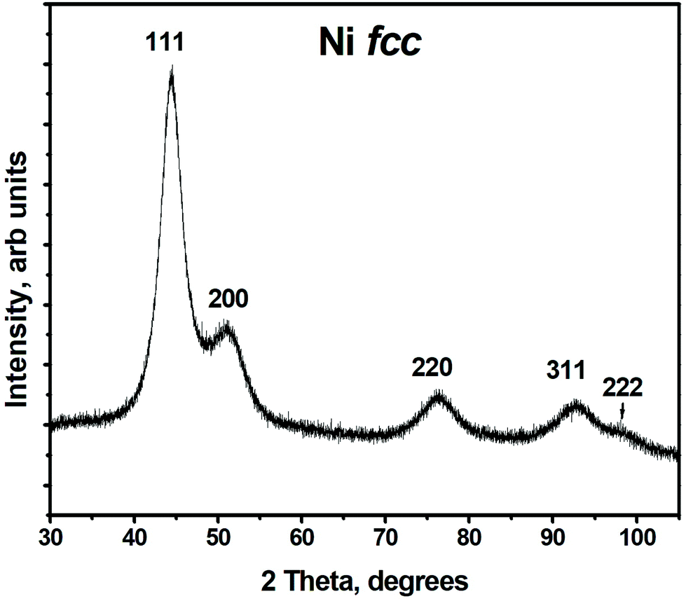 | ||
| Fig. 1 X-ray diffraction pattern of Ni nanoparticles, peaks are denoted with Miller indices corresponding to reflections from the respective planes for fcc Ni. | ||
High resolution transmission electron microscopy (HRTEM) study reveals that the precipitate consists of nanoparticles which form aggregates of irregular size and shape, see Fig. 2(A and B), more images are shown in ESI (Fig. S2†). The average particle size of 3.47 ± 0.71 nm, is determined using HRTEM images and considering 270 particles. The histogram of the particle size distribution is presented in Fig. 2D. Selected area electron diffraction (SAED) pattern was taken from the area highlighted in Fig. S2B (ESI†) and is presented in Fig. 2C. Note, the electron diffraction pattern reveals the presence of both fcc Ni and NiO compounds. The lattice parameter of fcc Ni is determined to 0.352 ± 0.001 nm. This value is in a good agreement with that determined from the XRD pattern. The structural characterization of NiO is a bit complicated since the SAED diffraction rings which correspond to the oxide are diffuse and very broad. The diffraction pattern shown in the figure may correspond to NiO, having both fcc cubic and rhombohedral structures, since the positions of the main peaks are very close to each other.38 Moreover, as shown in the literature, rhombohedral to cubic transformation in NiO may occur at room temperature due to a lattice contraction along the [111] direction caused by magnetic interactions.39 Indeed the interatomic distance between the planes in the [111] direction is about 0.238 nm in the studied sample, this is shorter than the interatomic distance in the same direction for a bulk cubic NiO (d(111) = 0.241 nm).38 Thus, TEM studies reveal that the synthesized material consist of metallic fcc Ni and NiO which structure undergoes rhombohedral distortions.
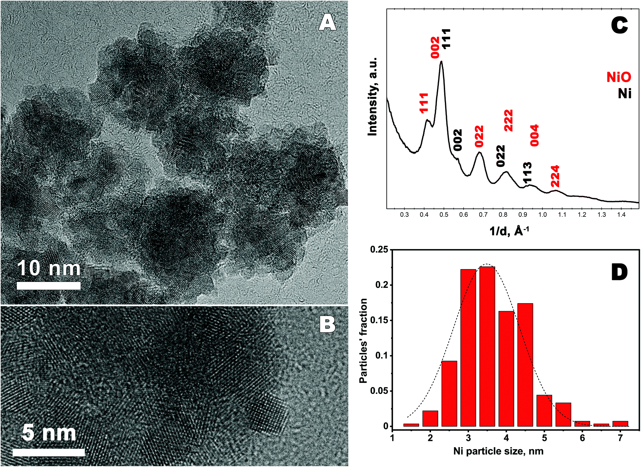 | ||
| Fig. 2 (A) and (B) High-resolution transmission electron microscopy images of Ni particles. (C) Azimuthal average profile obtained from the SAED pattern, indexed in fcc Ni and fcc NiO lattices. Miller indices of the corresponding reflections are denoted. (D) Ni particles size distribution obtained from HRTEM images. | ||
XPS is a surface sensitive spectroscopic technique that allows identification and determination of the chemical state of the elements which the material consist of. The geometry of the setup allows a maximum penetration depth of about 6 nm that is used in the current studies. Thus, the “bulk” composition of the synthesized nanomaterial can be obtained. In the current study XPS is used as a complementary study to XRD and TEM since it allows to determine the composition/presence of amorphous/poor-crystalline compounds. XPS results, in particular Ni 2p spectrum are shown in Fig. 3. As seen in the figure, there are sharp peaks at binding energies (BE) 852.3 eV and 869.3 eV, which correspond to metallic Ni.40 Other spectral maxima, such as Ni 2p3/2 peak with energy 855.5 eV and O 1s peak at 531.3 eV (not shown here) can be attributed to Ni(OH)2.41 There is also another peak for oxygen, O 1s, having binding energy at 529.2 eV present in the spectra. This peak can be attributed to NiO. Moreover, the Ni 2p3/2 binding energies for NiO is about 854.1 eV and 856.2 eV.42 These values are overlapping with BE values for Ni(OH)2, therefore the synthesized nanoparticles may contain both NiO and Ni(OH)2 in addition to metallic Ni.
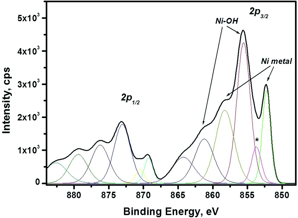 | ||
| Fig. 3 XPS spectra of Ni 2p line. Binding energies (BE) for metallic Ni, are 852.3 eV, 858.3 eV; and 869.3 eV, 876.3 eV for Ni 2p3/2 and 2p1/2 lines, respectively. BE which correspond to Ni(OH)2 are 855.5 eV, 861.3 eV and 873.0 eV; 879.5 eV, for Ni 2p3/2 and 2p1/2 lines, respectively. The line labelled with asterisk may originate as a tail from Ni 2p3/2 line or from Ni–C bonding. | ||
Thus, the investigation of the composition and the structure reveal that the obtained material consists of fcc metallic Ni particles with the diameter of 3.47 ± 0.71 nm, aggregated into larger clusters. The synthesized material also contains amorphous/poor-crystalline Ni(OH)2/NiO, as determined by TEM and XPS. Possible sources of Ni oxide/hydroxide formation may be oxidation of metallic Ni by water43 under filtering procedure, or/and in air, when the dry precipitate is removed from the glove-box. The further oxidation of the Ni precipitate outside glove-box can be affected by, for example, the air humidity and the temperature inside the laboratory.
Magnetic properties
The magnetic properties of Ni nanoparticles is characterized by recording both the magnetization (M) vs. temperature (T) and sample magnetization (M) vs. magnetic field strength (H) measurements. The results are presented in Fig. 4. In Fig. 4A field-cooled (FC) and zero-field cooled (ZFC) magnetization curves are plotted as a function of temperature. For ZFC measurements the sample is cooled down to 2 K in the absence of a magnetic field. Then a small field of μ0H = 5 mT is applied and the magnetization is recorded every 2 K while the sample is reheated up to 300 K at 2 K min−1. The FC magnetization is measured while cooling the samples to 2 K in the presence of a μ0H = 5 mT magnetic field. As seen in the figure, the ZFC-FC curves suggest a ferromagnetic-like behaviour and thus a significant magnetic interaction between the particles yielding a bulk like response.44 This behaviour may be attributed to the aggregation of small particles (3.47 ± 0.71 nm) to larger clusters, the existence of the latter is confirmed by TEM studies. As shown in the literature, aggregation favours the magnetic interactions between the particles inside the cluster.45,46 A magnetization hysteresis loop, shown in Fig. 4B, confirms the ferromagnetic behaviour, with a low coercive force (∼6 mT). The loop reveals that saturation magnetization is not completely reached at 5 T. The magnetisation, M, amounts at 5 T to about 34 Am2 kg−1. This value is significantly lower than that for the bulk Ni (55 Am2 kg−1).47 This may reflect the presence of Ni oxide/hydroxide layers (confirmed by XPS and TEM studies) which have lower magnetization.48 Moreover, the ferromagnetic-like behaviour and the decreased magnetization value indicate that the paramagnetic/antiferromagnetic Ni(OH)2/NiO layers49 form just on the surface of the aggregates while inside the clusters the nanoparticles are oxide-free and, therefore, are held together by the exchange interactions. The existence of significant magnetic interaction between the Ni nanoparticles is confirmed by the fact that the blocking temperature for the synthesized Ni (TB ≥ 300 K), shown in Fig. 4(A), is much higher than that for non-interacting Ni nanoparticles (TB ≈ 12 K) of the same size, reported in the literature.50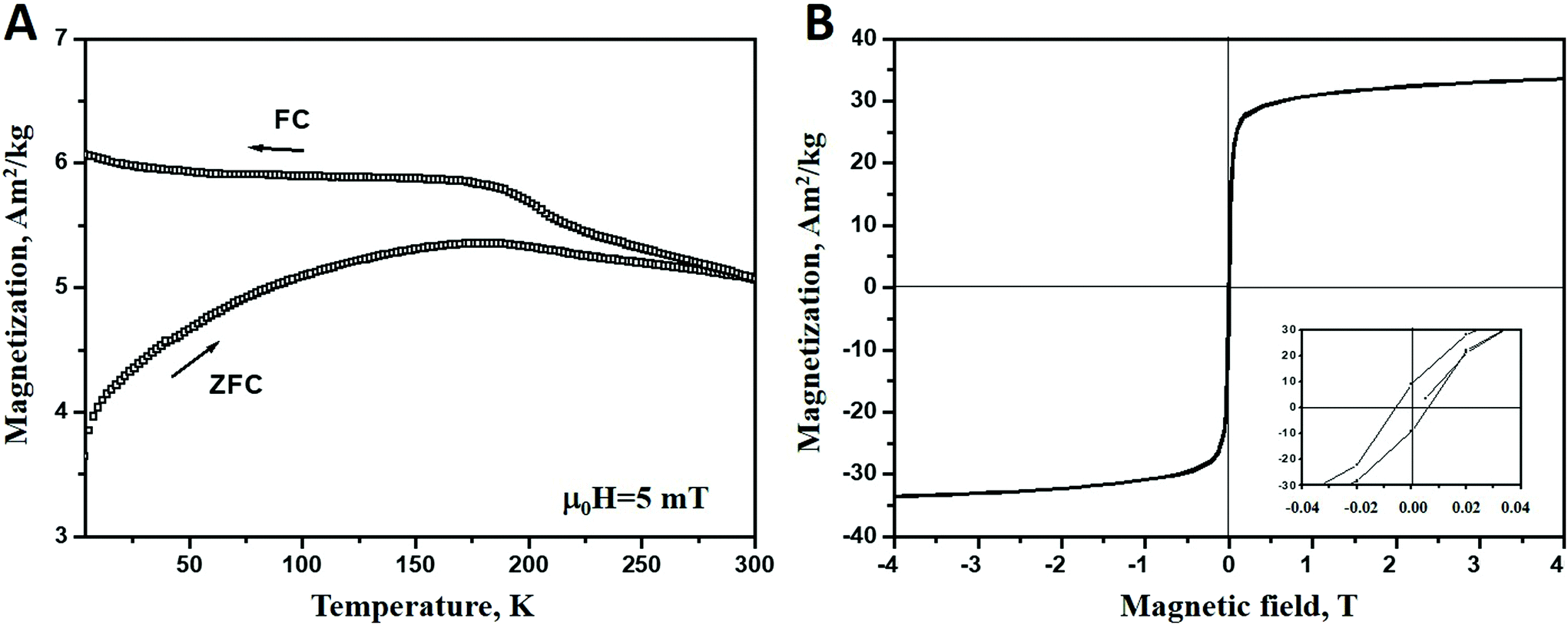 | ||
| Fig. 4 (A) Zero-field-cooled (ZFC) and field-cooled (FC) magnetization vs. temperature at an applied field of 4 kA m−1. The ordering temperature is above room temperature; (B) magnetization hysteresis loop measured at 2 K for fcc Ni particles. The insert shows hysteresis details at a low field. | ||
Electrochemical properties
Cyclic voltammetry (CV) is used to probe the oxidation state of the species as well as catalytic performance of the synthesized nanomaterial. CV curves of the synthesized Ni particles were recorded in 0.1 M N2 saturated KOH solution at different scan rates and shown in Fig. 5.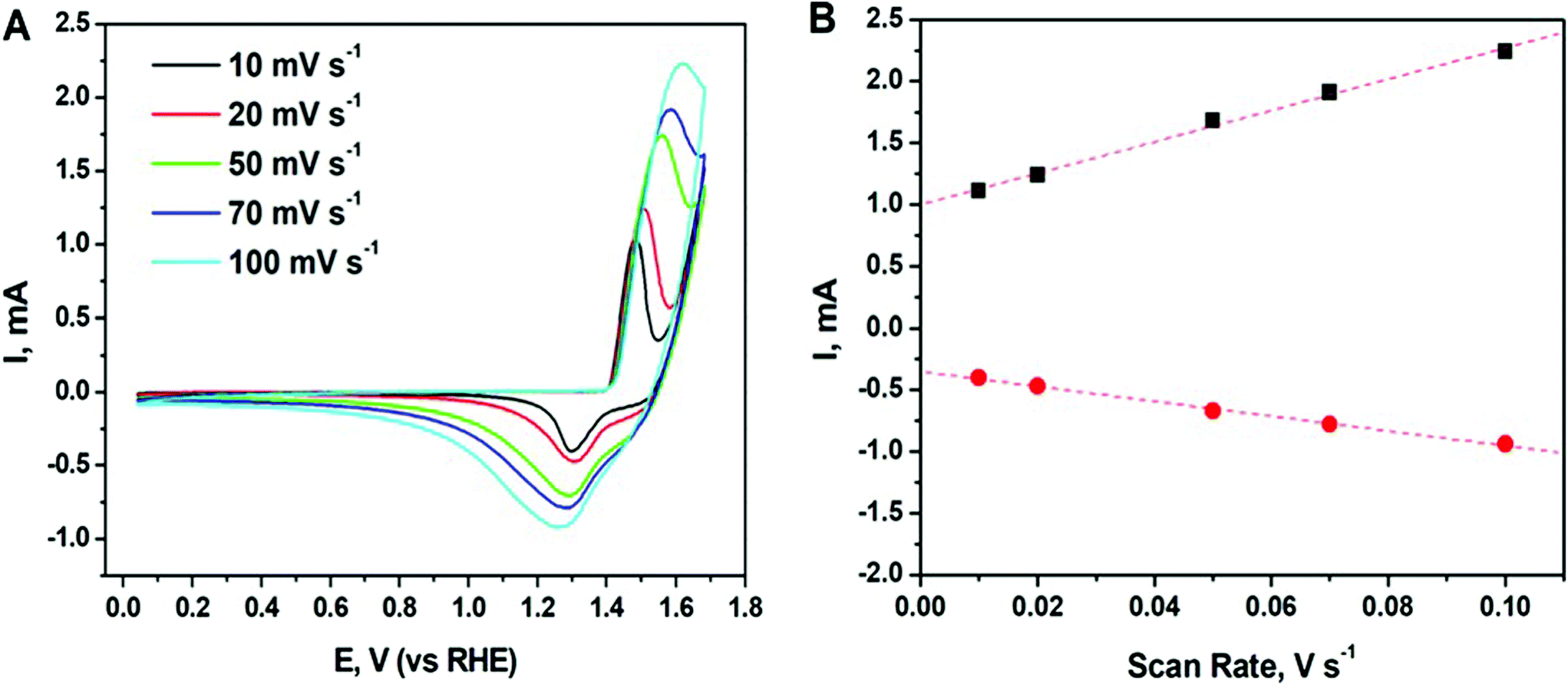 | ||
| Fig. 5 (A) Cyclic voltammetry (CV) curves of the synthesized Ni particles recorded in 0.1 M N2 saturated KOH solution at different scan rates; (B) cathodic (red solid circle) and anodic (black solid square) currents plotted as a function of scan rate. | ||
As seen in the figure, all CV curves exhibit a pair of well-defined redox peaks corresponding to the reversible conversion between Ni2+ and Ni0. Note, Ni can possess a mixed valence Ni2+/Ni3+ on the surface due to its partial oxidation. Oxidation peak appears at around 1.5 V at 10 mV s−1 and slightly shift to higher potentials at around 1.6 V when increasing the scan rate to 100 mV s−1. This peak may correspond to formation of Ni(OH)2/NiOOH.51 While the reduction peak of the reforming Ni appears at around 1.3 V at 10 mV s−1 and shift to the lower potentials at around 1.25 V. The measured potentials are consistent with the values reported in literature for Ni-based catalysts.52 Moreover, there is a linear dependence of both cathodic and anodic current on scan rate (see Fig. 5B), which indicates the good reversibility of the processes and the presence of diffusion-controlled faradaic redox reactions in Ni.53 Thus, the enhanced electrochemical performance of the Ni nanoparticles enables their use as efficient electrochemically active materials in pseudo-capacitors for the energy storage devices.52
Since the synthesized material consists of Ni nanoparticles agglomerated into larger clusters, the electrochemical surface area (ECSA) is one of the crucial parameters that governs its real electrochemical performance. In the current study, a double-layer capacitance (Cdl) method54,55 was applied to measure and calculate the ECSA of Ni nanoparticles, a commercial Ni powder (KEBO, diameter < 10 μm) was used as a reference. The experimental details and results are given in ESI.† The ECSA was calculated to be 39.15 m2 g−1 and 3.52 m2 g−1 for the Ni nanomaterial obtained in the current study and for the commercial Ni powder, respectively. As a result, the ECSA of the synthesized Ni is more than 10 times larger than that of the commercial Ni powder. This indicates a good potential for using the obtained nanomaterial for catalysis applications.
The presented material could also be employed as a precursor to fabricate Ni-based complexes with noble metals, such as Pt, Pd and Ag, to achieve increased electro-catalytic activity of the latter and decrease the amount of rare and expensive metals, such as Pt and Pd, in catalysts materials.7,56
Conclusions
γ-Radiation induced synthesis of unsupported, metallic Ni nanoparticles from aqueous solution of NiCl2 has been successfully performed. The particles are produced using γ-radiation induced reduction. To prevent re-oxidation of nickel the filtering and drying procedures were performed in protective atmosphere. Structural and compositional analyses are performed using XRD, TEM and XPS techniques. Those studies exhibit that the particles consist of fcc Ni nanoparticles with the average size of 3.47 ± 0.71 nm. These particles have a tendency to aggregate to larger clusters. Compositional analysis reveals that the material is partially oxidized and form amorphous/poor-crystalline Ni(OH)2/NiO. Considering magnetic characterization, performed by SQUID, that reveals that the synthesized particles exhibit ferromagnetic-like behaviour with significant magnetic interactions, we suggest that the existence of Ni(OH)2/NiO layers at the surface of the magnetic clusters decreases the material's overall magnetization value. Electrochemical measurements demonstrate that the synthesized nanomaterial has good electrochemical reversibility in the base electrolyte solutions, and its electrochemical surface area (of 39.15 m2 g−1) is at least 10 times higher than that for the commercial Ni powder. Thus, metallic Ni nanoparticles performed in the current study can be good candidates for the use as catalysts for energy storage devices.Conflicts of interest
There is no conflict of interest to declare.Acknowledgements
Y. Y. and I. L. S. acknowledge Swedish Foundation for Strategic Research (SSF) for the financial support of the current study and A. Shchukarev for XPS measurements. R. M. and F. S. acknowledge the support from Swedish Research Council (VR).References
- P.-Z. Li, A. Aijaz and Q. Xu, Angew. Chem., Int. Ed., 2012, 51, 6753–6756 CrossRef CAS PubMed.
- D. J. C. Yates, W. F. Taylor and J. H. Sinfelt, J. Am. Chem. Soc., 1964, 86(15), 2996–3001 CrossRef CAS.
- T. Umegaki, J.-M. Yan, X.-B. Zhang, H. Shioyama, N. Kuriyama and Q. Xu, J. Power Sources, 2009, 191(2), 209–216 CrossRef CAS.
- H. Huang, Z. Zhao, L. Cao, Y. Chen, E. Zhu, Z. Lin, M. Li, A. Yan, A. Zettl, Y. M. Wang, X. Duan, T. Mueller and Y. Huang, Science, 2015, 348(6240), 1230–1233 CrossRef PubMed.
- B. Li and J. Prakash, Electrochem. Commun., 2009, 11, 1162–1165 CrossRef CAS.
- K. Ravindhranath and M. Ramamoorty, Orient. J. Chem., 2017, 33(4), 1603–1613 CrossRef CAS.
- R. S. Nicholson and I. Shain, Anal. Chem., 1964, 36(4), 706–723 CrossRef CAS.
- Y. Hou, H. Kondoh, T. Ohta and S. Gao, Appl. Surf. Sci., 2001, 241(1–2), 218–222 Search PubMed.
- Y. Hou and S. Gao, J. Mater. Chem., 2003, 13(7), 1510–1512 RSC.
- D.-H. Chen and S.-H. Wu, Chem. Mater., 2000, 12(5), 1354–1360 CrossRef CAS.
- Y. Chen, D.-L. Peng, D. Lin and X. Luo, Nanotechnology, 2007, 18(50), 505703 CrossRef.
- F. L. Jia, L. Z. Zhang, X. Y. Shang and Y. Yang, Adv. Mater., 2008, 20, 1050–1054 CrossRef CAS.
- V. M. Rao, C. H. Castano, J. Rojas and A. J. Abdulghani, Radiat. Phys. Chem., 2013, 89, 51–56 CrossRef CAS.
- C. Dispenza, N. Grimaldi, M. A. Sabatino, I. L. Soroka and M. Jonsson, J. Nanosci. Nanotechnol., 2015, 15, 3445–3467 CrossRef CAS PubMed.
- H. Remita and S. Remita, Recent Trends in Radiation Chemistry, Chapter 13, Metal Clusters and Nanomaterials: Contribution of Radiation Chemistry, World Scientific Publishing Co., Singapore, 2010, pp. 347–383 Search PubMed.
- P. H. Borse, J. M. Yi, J. H. Je, W. L. Tsai and Y. Hwu, J. Appl. Phys., 2004, 95(3), 1166–1170 CrossRef CAS.
- A. Yamaguchi, I. Sakurai, I. Okada, H. Izumi, M. Ishihara, T. Fukuoka, S. Suzuki and Y. Utsumi, J. Synchrotron Radiat., 2020, 27(4), 1008–1014 CrossRef CAS PubMed.
- G. R. Dey, Radiat. Phys. Chem., 2005, 74(3–4), 172–184 CrossRef CAS.
- A. Yamaguchi, I. Okada, I. Sakurai, H. Izumi, M. Ishihara, T. Fukuoka, S. Suzuki, K. Elphick, E. Jackson, A. Hirohata and Y. Utsumi, J. Synchrotron Radiat., 2019, 26, 1986–1995 CrossRef CAS PubMed.
- J. Belloni, Contribution of radiation chemistry to metal clusters studies, in Centennial of Radioactivity Discovery, Special Issue of Radiation Research, ed. K. A. Mason and E. L. Travis, 1998, 150(suppl.), 9–20 Search PubMed.
- A. J. Berejka, Radiat. Phys. Chem., 1995, 46(4–6), 429–437 CrossRef CAS.
- A. Johgo, E. Ozawa, H. Ishida and K. Shoda, J. Mater. Sci. Lett., 1987, 6, 429–430 CrossRef CAS.
- E. A. Gulbransen and K. F. Andrew, J. Electrochem. Soc., 1954, 101, 128–140 CrossRef CAS.
- T. Uchikoshi, Y. Sakka, M. Yoshitake and K. Yoshihara, Nanostruct. Mater., 1994, 4(2), 199–206 CrossRef CAS.
- P. Song, D. Wen, Z. X. Guo and T. Korakianitis, Phys. Chem. Chem. Phys., 2008, 10, 5057–5065 RSC.
- J. Belloni, M. Mostafavi, H. Remita, J.-L. Marignier and M.-O. Delcourt, New J. Chem., 1998, 1239–1255 RSC.
- M. L. Hioul, M. Lin, J. Belloni, N. Keghouche and J.-L. Marignier, J. Phys. Chem. A, 2014, 118(40), 9319–9329 CrossRef CAS PubMed.
- J. Belloni, J.-L. Marignier and M. Mostafavi, Radiat. Phys. Chem., 2020, 169, 107972 CrossRef.
- S. Chettibi, Y. Benguedouar and N. Keghouche, Phys. Procedia, 2009, 2(3), 707–712 CrossRef CAS.
- S. Chettibi, N. Keghouche, Y. Benguedouar, M. M. Bettahar and J. Belloni, Catal. Lett., 2013, 143, 1166–1174 CrossRef CAS.
- I. L. Soroka, N. V. Tarakina, A. Hermansson, L. Bigum, R. Widerberg, M. S. Andersson, R. Mathieu, A. R. Paulraj and Y. Kiros, Dalton Trans., 2017, 46(30), 9995–10002 RSC.
- J. W. T. Spinks and R. J. Woods, An Introduction to Radiation Chemistry, Wiley, New York, 1990 Search PubMed.
- H. A. Schwarz, J. Chem. Educ., 1981, 58(2), 101–105 CrossRef CAS.
- J. Belloni, Catal. Today, 2006, 113, 141–156 CrossRef CAS.
- H. A. Schwarz and R. W. Dodson, J. Phys. Chem., 1989, 93(1), 409–414 CrossRef CAS.
- H. Wang, X. Zhao, X. Han, Z. Tang, S. Liu, W. Guo, C. Deng, Q. Guo, H. Wang, F. Wu, X. Meng and J. P. Giesy, Sci. Total Environ., 2017, 586(15), 817–826 CrossRef CAS PubMed.
- E. R. Jette and F. Foote, J. Chem. Phys., 1935, 3, 605–616 CrossRef CAS.
- I. Hotovy, J. Huran and L. Spiess, J. Mater. Sci., 2004, 39, 2609–2612 CrossRef CAS.
- M. W. Vernon, Phys. Status Solidi, 1970, 37, K1, DOI:10.1002/pssb.19700370153.
- P. T. Andrews, T. Collins and P. Weightman, J. Phys. C: Solid State Phys., 1981, 14, L957–L960 CrossRef CAS.
- K. Lian, S. J. Thorpe and D. W. Kirk, Electrochem. Acta, 1992, 37(11), 2029–2041 CrossRef CAS.
- A. N. Mansour, Surf. Sci. Spectra, 1994, 3(3), 231–238, DOI:10.1116/1.1247751.
- B. P. Payne, M. C. Biesinger and N. S. Mcintyre, J. Electron Spectrosc. Relat. Phenom., 2009, 175, 55–65 CrossRef CAS.
- Y. T. Jeon, J. Y. Moon, G. H. Lee, J. Park and Y. Chang, J. Phys. Chem. B, 2006, 110, 1187–1191 CrossRef CAS PubMed.
- L. Gutierrez, L. de la Cueva, M. Moros, E. Mazario, S. de Bernardo, J. M. de la Fuente, M. P. Morales and G. Salas, Nanotechnology, 2019, 30, 112001 CrossRef CAS PubMed (14pp).
- S. Tomita, P. E. Jönsson, K. Akamatsu, H. Nawafune and H. Takayama, Phys. Rev. B: Condens. Matter Mater. Phys., 2007, 76, 174432 CrossRef.
- V. Rodriguez-Gonzalez, E. Marceau, P. Beaunier, M. Che and C. Train, J. Solid State Chem., 2007, 180, 22–30 CrossRef CAS.
- K. H. Ang, I. Alexandrou, N. D. Mathur, G. A. J. Amaratunga and S. Haq, Nanotechnology, 2004, 15, 520–524 CrossRef CAS.
- J. Zhao, M. Yang and Z. Hua, J. Magn. Magn. Mater., 2014, 371, 10–13 CrossRef CAS.
- Y. Hou and S. Gao, J. Mater. Chem., 2003, 13, 1510–1512 RSC.
- K. Lian, S. J. Thorpe and D. W. Kirk, Electrochem. Acta, 1992, 37(11), 2029–2041 CrossRef CAS.
- J. Lin, H. Jia, H. Liang, S. Chen, Y. Cai, J. Qi, C. Qu, J. Cao, W. Fei and J. Feng, Adv. Sci., 2018, 5, 1700687 CrossRef PubMed (1–8).
- Z. Zhao, H. Liu, W. Gao, W. Xue, Z. Liu, J. Huang, X. Pan and Y. Huang, J. Am. Chem. Soc., 2018, 140(29), 9046–9050 CrossRef CAS PubMed.
- C. C. L. McCrory, S. Jung, J. C. Peters and T. F. Jaramillo, J. Am. Chem. Soc., 2013, 135(45), 16977–16987 CrossRef CAS PubMed.
- Z. Li, Y. Yang, A. Relefors, X. Kong, G. M. Siso, B. Wickman, Y. Kiros, I. L. Soroka and J. Colloid, Interface Sci., 2021, 583, 71–79 CrossRef CAS PubMed.
- D. Bhalothia, P.-C. Chen, C. Yan, K.-W. Wang and T.-Y. Chen, J. Phys. Chem. C, 2020, 124(4), 2295–2306 CrossRef CAS.
Footnote |
| † Electronic supplementary information (ESI) available. See DOI: 10.1039/d0dt03223a |
| This journal is © The Royal Society of Chemistry 2021 |