Amorphous Co3S4 nanoparticle-modified tubular g-C3N4 forms step-scheme heterojunctions for photocatalytic hydrogen production†
Yuanpeng
Wang
abc,
Xuqiang
Hao
abc,
Lijun
Zhang
abc,
Zhiliang
Jin
 *abcd and
Tiansheng
Zhao
 *d
*d
aSchool of Chemistry and Chemical Engineering, North Minzu University, Yinchuan 750021, P.R. China. E-mail: zl-jin@nun.edu.cn
bNingxia Key Laboratory of Solar Chemical Conversion Technology, North Minzu University, Yinchuan 750021, P.R. China
cKey Laboratory for Chemical Engineering and Technology, State Ethnic Affairs Commission, North Minzu University, Yinchuan 750021, P.R. China
dState Key Laboratory of High-efficiency Utilization of Coal and Green Chemical Engineering, Ningxia University, Yinchuan, 750021, P.R. China. E-mail: zhaots@nxu.edu.cn
First published on 18th November 2020
Abstract
An effective method to reduce the recombination rate of photogenerated electron–hole pairs was developed by the construction of heterojunctions with rationally designed photocatalysts having a matched band structure. Herein, g-C3N4 hexagonal tubes possessing a lower conduction band were coupled with Co3S4 ultra-fine nanoparticles having relatively higher positions for their conduction band. A step-scheme heterojunction was constructed between these two materials, and through this heterojunction, the spatial charge separation was boosted. The boosted spatial charge separation led to more useful electrons with a higher reduction ability that participated in a photocatalytic H2 evolution reaction. The Co3S4 ultra-fine nanoparticles act as a mirror to repeatedly scatter and reflect incident light and thus enhance light utilization, and they also accelerate the spatial charge separation. The photocatalytic H2 evolution activity of the composite catalyst reached 2120 μmol g−1 h−1, which was 176 times higher than that of pristine g-C3N4 tubes. A series of characteristics were determined to investigate the interaction that occurred between the g-C3N4 hexagonal tubes and the Co3S4 ultra-fine nanoparticles, and to study the mechanism of the formed step-scheme. This work will guide the design of step-scheme heterojunction-based photocatalysts to produce H2 from photocatalytic water splitting.
1. Introduction
The energy shortage and crisis have severely restricted sustainable development. Hydrogen (H2) is a clean and environmentally friendly energy that can be produced from photocatalytic water splitting using inexhaustible solar energy, and hydrogen has been regarded as a promising renewable energy to meet the energy shortage and crisis.1,2 Therefore, there has been an intense effort to discover an inexpensive, stable, and robust photocatalyst. Many photocatalysts such as metal-contained catalysts3–14 and graphdiyne (GD)15–17 or new members of carbon families or other metal-free catalysts18 have been widely researched. g-C3N4 is a new member of photocatalysts that is metal-free and shows great prospect in practical applications because it was first applied to produce H2 from water splitting by photocatalysis.19 Even though it possesses high thermal and chemical stability and it is a metal-free photocatalyst that can be easily obtained, bulk g-C3N4 is subjected to intrinsic drawbacks, such as low specific surface area, and severe recombination of photo-generated electron–hole pairs.20,21 Therefore, ongoing efforts have been devoted to solve these problems by resolving the deficiencies of bulk g-C3N4. Acquiring unique morphology and structure by adjusting synthetic methodologies will increase the specific surface area or make some adjustment to the band structure of g-C3N4 and increase the transfer efficiency of electron–holes in g-C3N4. Thus far, a host of different morphologies of g-C3N4, such as nanorods,22 seaweeds,23 nanosheets24 and tubular g-C3N4 (ref. 25–28) have been rationally designed to increase the light harvesting ability of g-C3N4 or to adjust its band structure to overcome the intrinsic drawbacks of bulk g-C3N4. Surprisingly, results can be obtained by constructing a certain morphology of photocatalysts. For instance, g-C3N4 with a nanotube shape can contribute a large specific surface area to provide a large number of active sites, and it also shortens the transfer distance of photo-induced carriers in g-C3N4 from the phase to its surface. In addition, tubular g-C3N4 with a hollow structure can enhance light absorption and increase the separation and transfer kinetics of photo-generated charge carriers by the multiple light scattering/reflection effect in the inner cavity of g-C3N4.Even though the different morphologies of g-C3N4 are rationally designed and all of them exhibit increased photocatalytic performance, the synthesis methods are time-consuming, expensive, and require hazardous reagents that are harmful to environment in the process of removing the template. Certain structured micro- or nano-materials are designed and obtained by treating supermolecular precursors that self-assemble through hydrogen bonding among molecules, and these materials are applied to many fields such as photocatalysis because the hydrogen bonding possesses features of strong direction and saturation.29,30 It is well known that using water as the solvent in the process of synthesis is more beneficial for the self-assembly of molecules based on hydrogen bonding because they can acquire precursors that are stable and large. Additionally, there are quite a few advantages such as inexpensive, easily obtained, and environmentally friendly when choosing water as the solvent to obtain supermolecular precursors.
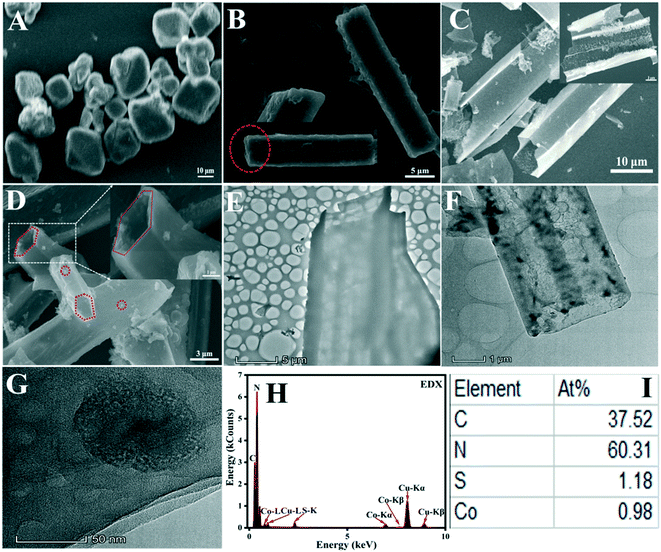
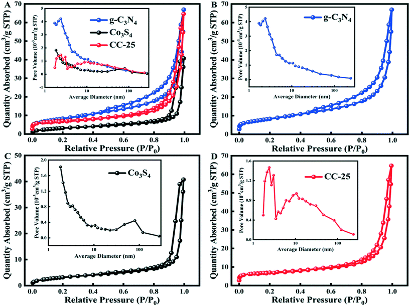
In this work, g-C3N4 with a tubular shape was fabricated by choosing deionized water as the solvent to synthesize supermolecular precursors and then calcine the precursors. Then, ultrafine Co3S4 nanoparticles were anchored on the surface of tubular g-C3N4 as cocatalyst to enhance the photocatalytic performance of g-C3N4. The results of emission scanning electron microscopy and transmission electron microscopy showed that the supermolecular precursors derived from melamine formed hollow g-C3N4 tubes, and ultrafine Co3S4 nanoparticles were distributed on the surface of the g-C3N4 tubes. The hollow structure enhances the light absorbed by g-C3N4, which is beneficial for the multiple light scattering/reflection effect in the inner cavity of g-C3N4. Even though the multiple light scattering/reflection effect in the inner cavity of g-C3N4 enhances its light absorption, light utilization is still inefficient in the outward wall because light entering into the tube can be utilized on both tails of the tube. The ultrafine Co3S4 nanoparticles distributed on the surface of the tube alter the relatively smooth surface of g-C3N4 so that it becomes uneven, resulting in the same scattering/reflection effect. The scattering/reflection effect occurring on the surface of g-C3N4 can enhance light utilization because ultrafine Co3S4 nanoparticles can act as a hole in an uneven mirror to scatter and reflect light irradiating to the surface of Co3S4 nanoparticles, and some light can be reflected to the surface of the g-C3N4 tube, which is the reason for the enhanced light absorption of g-C3N4.
2. Results and discussion
2.1 Structural and morphological analysis
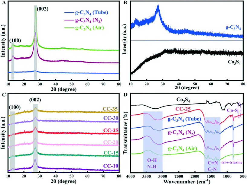
The chemical structures of g-C3N4 (synthesized with different methods), Co3S4, and CC-25 were analyzed employing the FT-IR spectra presented in Fig. 1D. The tubular g-C3N4 synthesized with a two-step hydrothermal method maintained a core structure that is similar to that of bulk g-C3N4 (prepared in air and nitrogen). The absorption band located at approximately 807 cm−1 can be assigned to the tri-s-triazine unit,26 which indicates a complete skeleton g-structure of g-C3N4. The absorption peaks located from 1200 to 1700 cm−1 are indexed to the C![[double bond, length as m-dash]](https://www.rsc.org/images/entities/char_e001.gif) N and C–N stretching vibration modes.32,33 The weak absorption peaks situated in the range from 3000 to 3600 cm−1 are the O–H and N–H stretching vibration modes.34 FTIR spectroscopy of Co3S4 shows a weak absorption peak that is centered at approximately 620 cm−1, and it can be indexed to the stretching vibrations of cobalt–sulphur bonds.35,36 In addition, the absorption peak of cobalt–sulphur bonds can be found in the FTIR pattern of CC-25, which indicates that g-C3N4 tubes and Co3S4 nanoparticles were successfully combined, and this can also be proved by the EDX results.
N and C–N stretching vibration modes.32,33 The weak absorption peaks situated in the range from 3000 to 3600 cm−1 are the O–H and N–H stretching vibration modes.34 FTIR spectroscopy of Co3S4 shows a weak absorption peak that is centered at approximately 620 cm−1, and it can be indexed to the stretching vibrations of cobalt–sulphur bonds.35,36 In addition, the absorption peak of cobalt–sulphur bonds can be found in the FTIR pattern of CC-25, which indicates that g-C3N4 tubes and Co3S4 nanoparticles were successfully combined, and this can also be proved by the EDX results.
![[double bond, length as m-dash]](https://www.rsc.org/images/entities/char_e001.gif) C (–N)2 group and the graphitic adventitious C
C (–N)2 group and the graphitic adventitious C![[double bond, length as m-dash]](https://www.rsc.org/images/entities/char_e001.gif) C/C–C bond in g-C3N4.37 The high-resolution XPS spectrum of N 1s (Fig. 3B) can be deconvoluted into four peaks, and these peaks with bonding energies of 404.3, 400.8, 399.7, and 398.6 eV can be indexed to π excitation of the C
C/C–C bond in g-C3N4.37 The high-resolution XPS spectrum of N 1s (Fig. 3B) can be deconvoluted into four peaks, and these peaks with bonding energies of 404.3, 400.8, 399.7, and 398.6 eV can be indexed to π excitation of the C![[double bond, length as m-dash]](https://www.rsc.org/images/entities/char_e001.gif) N, C–N–H, N–(C)3, and C–N
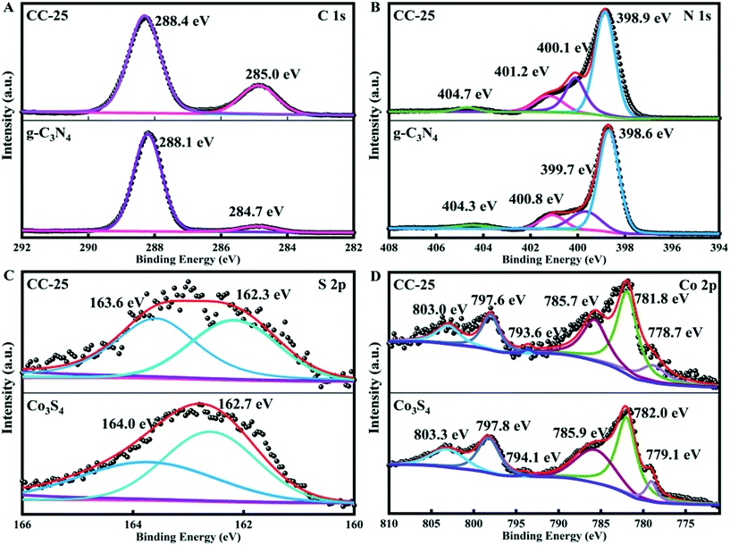
N, C–N–H, N–(C)3, and C–N![[double bond, length as m-dash]](https://www.rsc.org/images/entities/char_e001.gif) C conjugated structures in g-C3N4, respectively.38 There are two peaks with binding energies of 162.7 and 164.0 in the spectrum of S 2p (Fig. 3C), and the two peaks can be indexed to S (−II) in sulfide (CoSx).39 The high-resolution XPS spectrum of Co 2p presented in Fig. 3D contains six peaks. Those peaks with binding energies of 779.1 and 794.1 eV belong to Co 2p3/2 and Co 2p1/2, which are attributed to Co2+. The peaks centered at 782.0 and 797.8 eV can be assigned to Co 2p3/2 and Co 2p1/2, and indicate the existence of Co3+.40–42 The other two peaks with binding energies of 785.9 and 803.3 eV belong to satellites.41 In addition, the spectra of C 1s, N 1s, S 2p, and Co 2p of CC-25 were obtained, and the results are shown in Fig. 3. All binding energies of C 1s and N 1s in CC-25 shift towards higher energy, and binding energies of S 2p and Co 2p in CC-25 shift towards lower energy, which indicates that electrons are transferred from g-C3N4 tubes to Co3S4 ultrafine nanoparticles.
C conjugated structures in g-C3N4, respectively.38 There are two peaks with binding energies of 162.7 and 164.0 in the spectrum of S 2p (Fig. 3C), and the two peaks can be indexed to S (−II) in sulfide (CoSx).39 The high-resolution XPS spectrum of Co 2p presented in Fig. 3D contains six peaks. Those peaks with binding energies of 779.1 and 794.1 eV belong to Co 2p3/2 and Co 2p1/2, which are attributed to Co2+. The peaks centered at 782.0 and 797.8 eV can be assigned to Co 2p3/2 and Co 2p1/2, and indicate the existence of Co3+.40–42 The other two peaks with binding energies of 785.9 and 803.3 eV belong to satellites.41 In addition, the spectra of C 1s, N 1s, S 2p, and Co 2p of CC-25 were obtained, and the results are shown in Fig. 3. All binding energies of C 1s and N 1s in CC-25 shift towards higher energy, and binding energies of S 2p and Co 2p in CC-25 shift towards lower energy, which indicates that electrons are transferred from g-C3N4 tubes to Co3S4 ultrafine nanoparticles.
2.2 Optical absorption properties
The photocatalytic performance is affected to some extent by the optical absorption properties of catalysts. Fig. 5A shows the optical properties of bulk g-C3N4 prepared by calcining melamine in air (denoted as g-C3N4 (air)), bulk g-C3N4 prepared by calcining melamine in N2 atmosphere (denoted as g-C3N4 (N2)), and tubular g-C3N4. The absorption edge and the absorbance of the tubular g-C3N4 were lower than those of the two bulk-g-C3N4 samples when lower than 430 nm in the visible light region. However, the absorption edge of the g-C3N4 tubes shifts to a longer wavelength, and the absorbance becomes stronger than that of the counterparts of bulk g-C3N4 (air) when the incident light is located between 430 and 521 nm. Then, the absorbance of the tubular g-C3N4 continues to strengthen when the incident light increases its wavelength, and eventually, it becomes the strongest among the three samples, which is indicative of the enhanced light harvesting ability of tubular g-C3N4 itself. The enhanced light harvesting ability of tubular g-C3N4 can be attributed to the multiple light scattering/reflection effect in the inner cavity of tubular g-C3N4 (Scheme S2A†).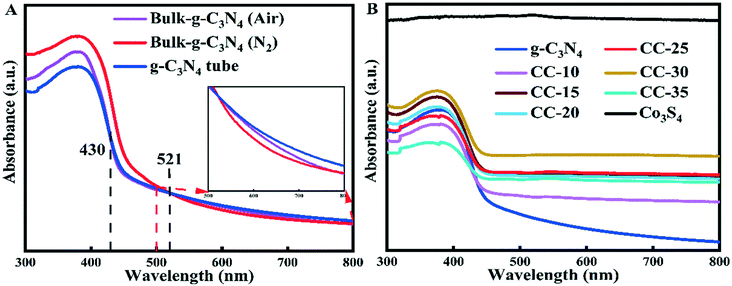 | ||
| Fig. 5 UV-vis diffuse reflectance spectra of (A) g-C3N4 (prepared under different conditions), (B) g-C3N4 tubes, Co3S4, and CC-x (x = 10, 15, 20, 25, 30, 35). | ||
The optical properties of g-C3N4 tubes, Co3S4, and CC-x (x = 10, 15, 20, 25, 30, 35) were studied using UV-vis diffuse reflectance spectra, as shown in Fig. 5B. The absorption edges of all composite samples shifted to a longer wavelength compared with the tubular g-C3N4, and the absorbance of these composite samples was higher than that of g-C3N4 tubes. The absorbance of the composite increases with an increase in the Co3S4 ultrafine nanoparticles loaded on the surface of g-C3N4 tubes. As depicted in Scheme S2B,† the ultrafine Co3S4 nanoparticles loaded on the surface of g-C3N4 tubes can act as a mirror with a rough surface to scatter and reflect the incident light. The incident light can be scattered and repeatedly reflected among the ultrafine Co3S4 nanoparticles. The light can also be reflected by the ultrafine Co3S4 nanoparticles toward different directions, and the scattered and reflected light will eventually irradiate to the surface of g-C3N4 tubes, which enhances the light harvesting ability of tubular g-C3N4, and this is the reason for the enhanced light absorbance of all composites. However, loading too many Co3S4 nanoparticles on the surface of g-C3N4 tubes will lead to a decrease in light absorbance because too many Co3S4 nanoparticles will hinder the incident light from irradiating to the surface of tubular g-C3N4 (Scheme S2C†).
2.3 Hydrogen evolution performance and stability
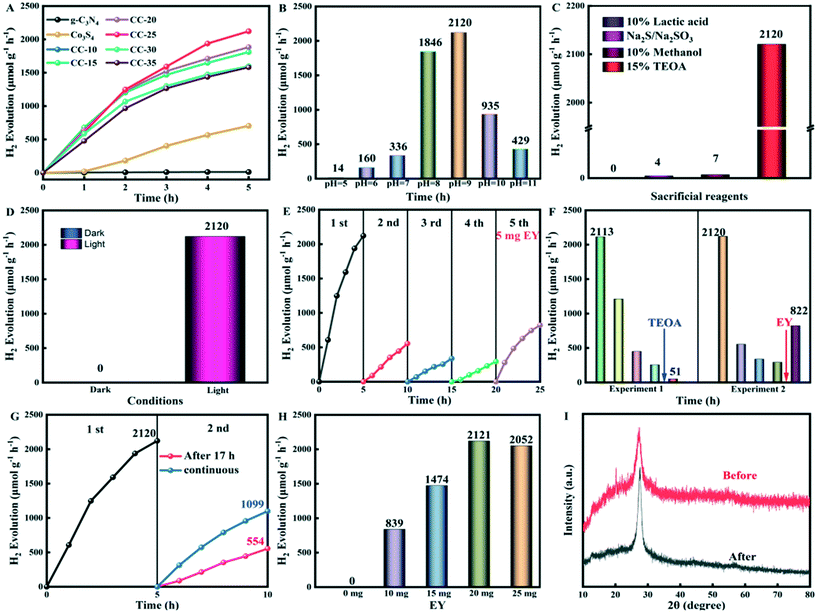
The photocatalytic H2 evolution performance of g-C3N4, Co3S4, and CC-x (x = 10, 15, 20, 25, 30, 35) at pH 9 was evaluated and is shown as Fig. 6A. The photocatalytic hydrogen evolution of tubular g-C3N4 is 12 μmol g−1 h−1. When the ultrafine Co3S4 nanoparticles are anchored on the surface of g-C3N4 tubes, the photocatalytic hydrogen evolution drastically increases. The photocatalytic hydrogen evolution of CC-25 is 2120 μmol g−1 h−1, which is 176 times higher than that of pure tubular g-C3N4. The photocatalytic hydrogen evolution of CC-25 at different pH values was carried out, and the results are shown in Fig. 6B, from which it can be seen that the highest hydrogen evolution performance occurred at pH 9, which is indicative that it is an appropriate pH value that is suitable for hydrogen evolution. The hydrogen evolution of CC-25 decreases when the pH value is higher than 9, which likely occurs due to the decreased concentration of H+, and thus, a decreased thermodynamic driving force for hydrogen evolution. It also was likely due to the strengthened electrostatic repulsion forces between the deprotonated EY and the negatively charged g-C3N4 tubes. However, lowering the pH to 8 also leads to a decrease in the hydrogen evolution of CC-25, and the H2 evolution performance is drastically decreased when the pH value is lowered to 5. This can be explained in that an overly acidic environment will result in the protonation of triethanolamine (TEOA). Then, TEOA becomes an ineffective electron donor, and as a consequence, the H2 evolution performance decreases. Fig. 6C shows the H2 evolution performance of CC-25 in different sacrificial reagents, including 10% lactic acid, Na2S/Na2SO3 (0.35 M/0.25 M), 15% methanol, and 15% TEOA (pH 9). The photocatalytic activity of CC-25 in 15% TEOA (pH 9) in the presence of EY is the highest and is far beyond that of other sacrificial reagents, demonstrating that the composite catalyst CC-25 is selective of sacrificial reagents, and 15% TEOA (pH 9) is the most suitable for photocatalytic H2 evolution among these four sacrificial reagents. EY was added to the system as a sensitizer to enhance the photocatalytic hydrogen evolution activity of CC-25. TEOA (15%), as the sacrificial reagent, not only can consume photogenerated holes at the valence band of g-C3N4 tubes, but it also provides electrons for the transformation of EY from the triplet excited state (EY3*) to the transition state (EY˙−), and at last, the transition state EY can provide electrons to photocatalysts to participate in the H2 evolution reaction. For the other three sacrificial reagents, they can act as hole consumers instead of playing the role of electron donor to provide electrons to EY for its transformation between different excited states. Therefore, the photocatalytic hydrogen evolution of CC-25 in TEOA is much higher than that in other three sacrificial reagents. The hydrogen evolution of CC-25 in the dark and under the irradiation of visible light conditions was performed and is presented in Fig. 6D. There was no H2 produced when the lights were turned off, and it lasted for 5 h because electron–hole pairs cannot be excited.The photocatalytic hydrogen evolution stability test of CC-25 was implemented in TEOA (pH 9) in the presence of EY, and the result is displayed in Fig. 6E. The hydrogen evolution performance of the composite catalyst was excellent in the first run, which lasted for 5 h. However, it drastically decreased when the test proceeded to the second run, and then decreased by inches in the third and the fourth runs. The drastic decrease in the second, third, and fourth runs compared with the first run can probably be attributed to two aspects. The sacrificial reagent (TEOA) in the reaction bottle was consumed because no extra TEOA was added to the reaction bottle. However, EY was degraded under the illumination of visible light in the presence of TEOA. Some extra experiments were conducted (presented in Fig. 6F) to confirm the proposed hypothesis above. In the first control experiment, the sacrificial reagent was changed in the fifth run but without adding any EY, and the hydrogen performance did not recover, but instead, continued to fall. In the second control experiment, five milligrams of EY were added to the reaction bottle in the fifth run without changing or adding the sacrificial reagent (TEOA). Then, the hydrogen evolution recovered, and it was almost 3 times higher than that of the fourth run. These results indicate that a drastic decrease in the photocatalytic hydrogen performance of CC-25 is not irrelevant to the consumption of TEOA. The hydrogen evolution performance of CC-25 in the stability test sharply decreased during the second run, which can probably be attributed to the degradation of EY under visible light because there was an interval of 17 h between the first and second runs. A control experiment was carried out to clarify what we surmised above, and the result is displayed in Fig. 6G. The hydrogen performance of CC-25 at the second run decreased almost 74% from 2120 to 554 when there was an interval of 17 h between the first and the second runs. However, the hydrogen performance of CC-25 at the second run only decreased 49% from 2120 to 1099 when the second run was carried out immediately after the first run. These results indicate that the drastic decrease in the hydrogen evolution performance of CC-25 is attributed to the degradation of EY. Also, Fig. 6I shows the XRD patterns of CC-25 before and after the photocatalytic hydrogen evolution stability tests were conducted, and there is no obvious shift in characteristic peaks, which indicates that the composite is stable. The SEM image of CC-25 after photocatalytic hydrogen evolution was implemented is shown in Fig. S4,† which also confirms the stability of the composite. Fig. 6H shows the experiment where different amounts of EY were added to the reaction system to determine the most suitable amount for photocatalytic hydrogen evolution. No H2 can be produced when the amount of EY is 0 mg. Then, the hydrogen evolution increases with increasing amounts of added EY, but hydrogen performance decreases when excessive amounts of EY were added to the system. When the amount of EY is insufficient, it cannot provide enough electrons for the hydrogen evolution reaction. Conversely, excessive EY in the reaction system will create a shielding effect that is not beneficial for the hydrogen evolution reaction.
2.4 Transfer kinetics of charges
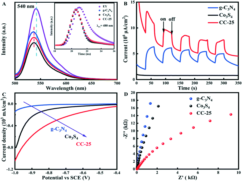
The transfer kinetics of photo-generated charge carriers were studied by obtaining photoluminescence (PL) and time-resolved photoluminescence (TRPL) spectra, transient photocurrent response (IT) and electrochemical impedance (EIS) spectra, and linear scan voltammetry (LSV) spectra (Fig. 7). The intensity of the fluorescence can reflect the recombination rate of the electron–hole pairs because the recombination of photo-induced electron–hole pairs will emit fluorescence, and the fluorescence can be recorded. As depicted in Fig. 7A, the EY solution (1 × 10⁻⁶ mol L−1) exhibits a typical emission peak at approximately 540 nm when excited at 480 nm, being assigned to the conjugated xanthene structure with severe recombination of photogenerated electron–hole pairs. However, the emission peaks of EY-sensitized g-C3N4, Co3S4, and CC-25 exhibited a blueshift compared with pristine EY, which can be attributed to the strong interaction that occurred between EY and each pristine sample. The intensity of the emission peak decreased when tubular g-C3N4 was added to EY solution, and that of EY-sensitized Co3S4 ultrafine nanoparticles decreased to a lower status, which revealed that photogenerated electrons from EY* are easily transferred to Co3S4 nanoparticles. The estimated potential of EY* (−3.45 eV)43 is more negative than that of the conduction bands of tubular g-C3N4 (−1.02 eV) and Co3S4 (−1.41 eV) ultrafine nanoparticles, which creates a difference in the energy levels, and this enables electrons to be transferred from EY to g-C3N4 tubes and Co3S4 nanoparticles. Additionally, the PL intensity of CC-25 tested in EY aqueous solution further decreased compared to pristine g-C3N4 after introducing Co3S4 ultrafine nanoparticles. This indicated that electrons from the photoexcited EY* can be separated and transferred to g-C3N4 tubes and Co3S4 nanoparticles, which resulted in PL quenching of EY. Fig. 7B shows that the photocurrent intensity of CC-25 was the lowest among the three samples, demonstrating that EY-sensitized CC-25 exhibited the lowest recombination rate of photogenerated electron–hole pairs. A more efficient transfer and separation can be obtained by introducing Co3S4 ultrafine nanoparticles to form heterojunctions with tubular g-C3N4. The polarization curves of CC-25 (Fig. 7C) exhibited the lowest onset potential among these three samples, revealing an excellent performance in lowering the H2-evolution overpotential. In addition, the electrochemical impedance spectroscopy (Fig. 7D) of CC-25 carried out in 0.2 M Na2SO4 solution showed a lower arc radius compared with those of pristine g-C3N4 tubes and Co3S4 ultrafine nanoparticles, which indicated that the introduction of Co3S4 accelerated the transfer and separation of electrons between these two components, thus promoting photocatalytic hydrogen evolution. The enhanced transfer and separation of photogenerated charge carriers leads to additional electrons that can be utilized in the hydrogen evolution reaction (Table 2).2.5 Band structure
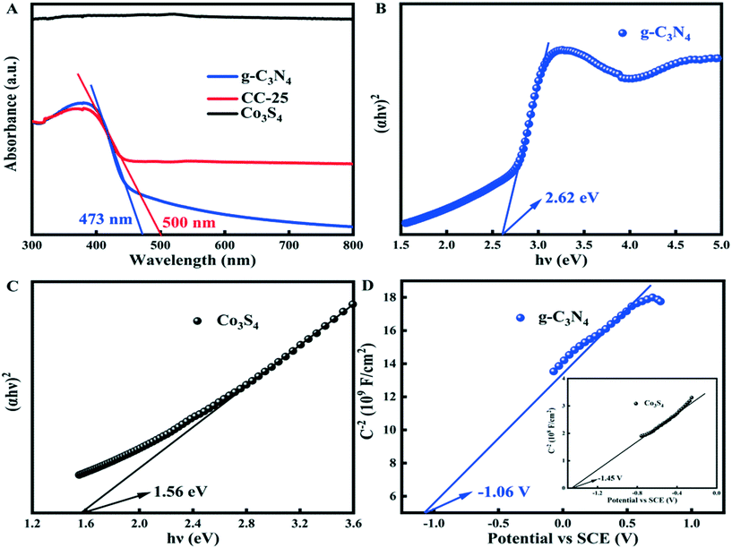
The UV-vis diffuse reflectance spectra of g-C3N4, Co3S4, and CC-25 (Fig. 8A) show that the absorption edge and absorbance of CC-25 shift toward larger wavelengths and become stronger after coupling with Co3S4 ultrafine nanoparticles and g-C3N4 tubes. Fig. 8B and C show the band gaps of g-C3N4 tubes and Co3S4 nanoparticles, and Fig. 8D shows the Mott–Schottky curves of g-C3N4 tubes and Co3S4 nanoparticles. It is well known that the conduction band of an n-type semiconductor is more negative by approximately −0.2 or −0.1 eV than its flat band.44,45 Hence, the conduction bands of g-C3N4 and Co3S4 were calculated to be −1.26 and −1.65 V vs. SCE (saturate calomel electrode), and the conduction bands of these two components can also be presented as −1.02 and −1.41 V vs. NHE (normal hydrogen electrode) (ENHE = ESCE + 0.241 V).46–48 In addition, the valance band of g-C3N4 and Co3S4 was determined to be 1.6 and 0.15 V by the equation: EVB = ECB + Eg.2.6 Reaction mechanism
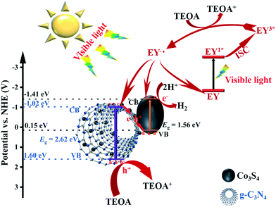
The light-harvesting performance of tubular g-C3N4 can be enhanced through the multiple scatter/reflection effect that occurs in the inner cavity of g-C3N4. Additionally, the amorphous Co3S4 ultrafine nanoparticles anchored on the outside surface of g-C3N4 tubes can act as a mirror to scatter and reflect light, thus enhancing the light-harvesting performance of the composite catalyst. A possible mechanism for the photocatalytic hydrogen evolution is proposed (Fig. 9) to more optimally understand the entire process of photocatalysis based on all the results discussed in the above sections. Singlet excited states of EY1* can be produced after absorbing light by EY, and then, the singlet excited states will produce triplet excited states EY3* through fast intersystem crossing (ISC).49 The triplet excited states EY3* are reductively quenched when TEOA is added to the system, producing EY˙−. Electrons from EY˙− can be transferred to the conduction bands of the Co3S4 ultrafine nanoparticles and g-C3N4 tubes, and at the same time, parts of EY˙− return to the ground state. Additionally, g-C3N4 itself can be excited by absorbing light with energy that exceeds its band gap. Then, electron–hole pairs are excited, and electrons are later transferred to the conduction band (CB) of g-C3N4 tubes. Co3S4 ultra-fine nanoparticles can also be excited by visible light in a process similar to that which g-C3N4 tubes undergo. Electrons from the CB of g-C3N4 tubes and holes from the valence band (VB) of Co3S4 ultrafine nanoparticles recombine in the interface after these two semiconductors are excited by visible light, and through this, the recombination rate of electron–hole pairs in both of the materials is reduced. The solid–solid contact between these two materials forms a “Step-scheme” transfer route between them, in which electrons from the CB of g-C3N4 and holes from the VB of Co3S4 recombine in their interface. For g-C3N4 tubes, electrons are excited and transferred to its CB, and then subsequently transferred to the VB of Co3S4 to recombine with photoexcited holes. For Co3S4, photoexcited holes are consumed by electrons from the CB of g-C3N4, and electrons are transferred to the CB where H2 is produced.3. Conclusion
In summary, we successfully synthesized a heterojunction composed of ultrafine Co3S4 nanoparticles on g-C3N4 tubes. The light harvesting of g-C3N4 was enhanced due to the scatter and reflect effect in the inner cavity of the g-C3N4 tubes. The introduced Co3S4 ultrafine nanoparticles act as a mirror to repeatedly scatter and reflect incident light, which enhances light utilization. The composite catalyst performed a photocatalytic hydrogen evolution activity that was significantly improved (176 times) compared with pristine g-C3N4 tubes in the visible light region. Such a significant improvement in the performance of photocatalytic H2 production can be attributed to the formation of a step-scheme heterojunction between the two materials. This work will provide guidance for studying the step-scheme photocatalysts.Author contributions
Yuanpeng Wang and Xuqiang Hao designed the experiments, Zhiliang Jin and Tiansheng Zhao contributed reagents/materials and analysis tools, and Yuanpeng Wang and Lijun Zhang wrote the paper.Conflicts of interest
The authors declare that they have no conflicts of interest.Acknowledgements
This work was financially supported by the Natural Science Foundation of the Ningxia Hui Autonomous Region (2020AAC03204 and 2020AAC03208 and 2020AAC02026), the Open Project of State Key Laboratory of High-efficiency Utilization of Coal and Green Chemical Engineering, Ningxia University (2019-KF-36).References
- L. Yin, S. Wang, C. Yang, S. Lyu and X. Wang, Modulation of Polymeric Carbon Nitrides through Supramolecular Preorganization for Efficient Photocatalytic Hydrogen Generation, ChemSusChem, 2019, 12, 3320–3325 CrossRef CAS.
- J. Fu, Q. Xu, J. Low, C. Jiang and J. Yu, Ultrathin 2D/2D WO3/g-C3N4 step-scheme H2-production photocatalyst, Appl. Catal., B, 2019, 243, 556–565 CrossRef CAS.
- X. Meng, C. Zhang, C. Dong, W. Sun, D. Ji and Y. Ding, Carbon quantum dots assisted strategy to synthesize Co@NC for boosting photocatalytic hydrogen evolution performance of CdS, Chem. Eng. J., 2020, 389, 124432 CrossRef CAS.
- M. Zhang, Q. Hu, K. Ma, Y. Ding and C. Li, Pyroelectric effect in CdS nanorods decorated with a molecular Co-catalyst for hydrogen evolution, Nano Energy, 2020, 73, 104810 CrossRef CAS.
- H. Gong, Z. Li, Z. Chen, Q. Liu, M. Song and C. Huang, NiSe/Cd0.5Zn0.5S Composite Nanoparticles for Use in p–n Heterojunction-Based Photocatalysts for Solar Energy Harvesting, ACS Appl. Nano Mater., 2020, 3, 3665–3674 CrossRef CAS.
- Z. Chen, H. Gong, Q. Liu, M. Song and C. Huang, NiSe2 Nanoparticles Grown in Situ on CdS Nanorods for Enhanced Photocatalytic Hydrogen Evolution, ACS Sustainable Chem. Eng., 2019, 7, 16720–16728 CrossRef CAS.
- Y. Li, H. Li, Y. Li, S. Peng and Y. H. Hu, Fe-B alloy coupled with Fe clusters as an efficient cocatalyst for photocatalytic hydrogen evolution, Chem. Eng. J., 2018, 344, 506–513 CrossRef CAS.
- Y. Li, Z. Jin, L. Zhang and K. Fan, Controllable design of Zn-Ni-P on g-C3N4 for efficient photocatalytic hydrogen production, Chin. J. Catal., 2019, 40, 390–402 CrossRef CAS.
- T. Jia, F. Fu, J. Li, Z. Deng, F. Long, D. Yu, Q. Cui and W. Wang, Rational construction of direct Z-scheme SnS/g-C3N4 hybrid photocatalyst for significant enhancement of visible-light photocatalytic activity, Appl. Surf. Sci., 2020, 499, 143941 CrossRef CAS.
- T. Jia, F. Fu, D. Yu, J. Cao and G. Sun, Facile synthesis and characterization of N-doped TiO2/C nanocomposites with enhanced visible-light photocatalytic performance, Appl. Surf. Sci., 2018, 430, 438–447 CrossRef CAS.
- T. Jia, F. Fu, J. Li, W. Wang and X. Hu, Constructing a novel Zn2SnO4/C/AgBr nanocomposite with extended spectral response and improved photocatalytic performance, J. Alloys Compd., 2019, 783, 687–696 CrossRef CAS.
- L. Su, L. Luo, H. Song, Z. Wu, W. Tu, Z.-j. Wang and J. Ye, Hemispherical shell-thin lamellar WS2 porous structures composited with CdS photocatalysts for enhanced H2 evolution, Chem. Eng. J., 2020, 388, 124346 CrossRef CAS.
- F. Yang, D. Liu, Y. Li, L. Cheng and J. Ye, Lithium incorporation assisted synthesis of ultra-small Mo2C nanodots as efficient photocatalytic H2 evolution cocatalysts, Chem. Eng. J., 2020, 399, 125794 CrossRef CAS.
- H. Lin, K. Zhang, G. Yang, Y. Li, X. Liu, K. Chang, Y. Xuan and J. Ye, Ultrafine nano 1T-MoS2 monolayers with NiOx as dual co-catalysts over TiO2 photoharvester for efficient photocatalytic hydrogen evolution, Appl. Catal., B, 2020, 279, 119387 CrossRef CAS.
- Q. Xu, B. Zhu, B. Cheng, J. Yu, M. Zhou and W. Ho, Photocatalytic H2 evolution on graphdiyne/g-C3N4 hybrid nanocomposites, Appl. Catal., B, 2019, 255, 117770 CrossRef CAS.
- Z. Jin, L. Zhang, G. Wang, Y. Li and Y. Wang, Graphdiyne formed a novel CuI-GD/g-C3N4 S-scheme heterojunction composite for efficient photocatalytic hydrogen evolution, Sustainable Energy Fuels, 2020, 4, 5088–5101 RSC.
- Y. Li, H. Yang, G. Wang, B. Ma and Z. Jin, Distinctive Improved Synthesis and Application Extensions Graphdiyne for Efficient Photocatalytic Hydrogen Evolution, ChemCatChem, 2020, 12, 1985–1995 CrossRef CAS.
- X. Li, J. Xiong, X. Gao, J. Ma, Z. Chen, B. Kang, J. Liu, H. Li, Z. Feng and J. Huang, Novel BP/BiOBr S-scheme nano-heterojunction for enhanced visible-light photocatalytic tetracycline removal and oxygen evolution activity, J. Hazard. Mater., 2020, 387, 121690 CrossRef CAS.
- X. Wang, K. Maeda, A. Thomas, K. Takanabe, G. Xin, J. M. Carlsson, K. Domen and M. Antonietti, A metal-free polymeric photocatalyst for hydrogen production from water under visible light, Nat. Mater., 2008, 8, 76–80 CrossRef.
- H. Wang, X. Li and J. Yang, The g-C3N4/C2N Nanocomposite: A g-C3N4-Based Water-Splitting Photocatalyst with Enhanced Energy Efficiency, ChemPhysChem, 2016, 17, 2100–2104 CrossRef CAS.
- Z. Zeng, H. Yu, X. Quan, S. Chen and S. Zhang, Structuring phase junction between tri-s-triazine and triazine crystalline C3N4 for efficient photocatalytic hydrogen evolution, Appl. Catal., B, 2018, 227, 153–160 CrossRef CAS.
- Z. You, Y. Su, Y. Yu, H. Wang, T. Qin, F. Zhang, Q. Shen and H. Yang, Preparation of g-C3N4 nanorod/InVO4 hollow sphere composite with enhanced visible-light photocatalytic activities, Appl. Catal., B, 2017, 213, 127–135 CrossRef CAS.
- Q. Han, B. Wang, Y. Zhao, C. Hu and L. Qu, A Graphitic-C3N4 “Seaweed” Architecture for Enhanced Hydrogen Evolution, Angew. Chem., Int. Ed., 2015, 54, 11433–11437 CrossRef CAS.
- Y. Li, R. Jin, Y. Xing, J. Li, S. Song, X. Liu, M. Li and R. Jin, Macroscopic Foam-Like Holey Ultrathin g-C3N4 Nanosheets for Drastic Improvement of Visible-Light Photocatalytic Activity, Adv. Energy Mater., 2016, 6, 1601273 CrossRef.
- Y. Li, M. Gu, T. Shi, W. Cui, X. Zhang, F. Dong, J. Cheng, J. Fan and K. Lv, Carbon vacancy in C3N4 nanotube: Electronic structure, photocatalysis mechanism and highly enhanced activity, Appl. Catal., B, 2020, 262, 118281 CrossRef CAS.
- S. Wan, M. Ou, Y. Wang, Y. Zeng, Y. Xiong, F. Song, J. Ding, W. Cai, S. Zhang and Q. Zhong, Protonic acid-assisted universal synthesis of defect abundant multifunction carbon nitride semiconductor for highly-efficient visible light photocatalytic applications, Appl. Catal., B, 2019, 258, 118011 CrossRef CAS.
- D. Long, W. Chen, S. Zheng, X. Rao and Y. Zhang, Barium- and Phosphorus-Codoped g-C3N4 Microtubes with Efficient Photocatalytic H2 Evolution under Visible Light Irradiation, Ind. Eng. Chem. Res., 2020, 59, 4549–4556 CrossRef CAS.
- Y. Hong, L. Wang, E. Liu, J. Chen, Z. Wang, S. Zhang, X. Lin, X. Duan and J. Shi, A curly architectured graphitic carbon nitride (g-C3N4) towards efficient visible-light photocatalytic H2 evolution, Inorg. Chem. Front., 2020, 7, 347–355 RSC.
- N. A. Wasio, R. C. Quardokus, R. P. Forrest, C. S. Lent, S. A. Corcelli, J. A. Christie, K. W. Henderson and S. A. Kandel, Self-assembly of hydrogen-bonded two-dimensional quasicrystals, Nature, 2014, 507, 86–89 CrossRef CAS.
- T. Jordan, N. Fechler, J. Xu, T. J. K. Brenner, M. Antonietti and M. Shalom, “Caffeine Doping” of Carbon/Nitrogen-Based Organic Catalysts: Caffeine as a Supramolecular Edge Modifier for the Synthesis of Photoactive Carbon Nitride Tubes, ChemCatChem, 2015, 7, 2826–2830 CrossRef CAS.
- J. Zhang, X. Chen, K. Takanabe, K. Maeda, K. Domen, J. D. Epping, X. Fu, M. Antonietti and X. Wang, Synthesis of a Carbon Nitride Structure for Visible-Light Catalysis by Copolymerization, Angew. Chem., Int. Ed., 2010, 49, 441–444 CrossRef CAS.
- H. Ye, Z. Wang, F. Yu, S. Zhang, K. Kong, X. Gong, J. Hua and H. Tian, Fluorinated conjugated poly(benzotriazole)/g-C3N4 heterojunctions for significantly enhancing photocatalytic H2 evolution, Appl. Catal., B, 2020, 267, 118577 CrossRef CAS.
- Y. Chen, F. Su, H. Xie, R. Wang, C. Ding, J. Huang, Y. Xu and L. Ye, One-step construction of S-scheme heterojunctions of N-doped MoS2 and S-doped g-C3N4 for enhanced photocatalytic hydrogen evolution, Chem. Eng. J., 2021, 404, 126498 CrossRef CAS.
- M. Wu, J. Zhang, B.-b. He, H.-w. Wang, R. Wang and Y.-s. Gong, In-situ construction of coral-like porous P-doped g-C3N4 tubes with hybrid 1D/2D architecture and high efficient photocatalytic hydrogen evolution, Appl. Catal., B, 2019, 241, 159–166 CrossRef CAS.
- W. Li, Y. Li, C. Yang, Q. Ma, K. Tao and L. Han, Fabrication of 2D/2D nanosheet heterostructures of ZIF-derived Co3S4 and g-C3N4 for asymmetric supercapacitors with superior cycling stability, Dalton Trans., 2020, 49, 14017–14029 RSC.
- V. Shrivastav, S. Sundriyal, P. Goel, V. Shrivastav, U. K. Tiwari and A. Deep, ZIF-67 derived Co3S4 hollow microspheres and WS2 nanorods as a hybrid electrode material for flexible 2V solid-state supercapacitor, Electrochim. Acta, 2020, 345, 136194 CrossRef CAS.
- Z. Liang, S. Yang, X. Wang, H. Cui, X. Wang and J. Tian, The metallic 1T-phase WS2 nanosheets as cocatalysts for enhancing the photocatalytic hydrogen evolution of g-C3N4 nanotubes, Appl. Catal., B, 2020, 274, 119114 CrossRef CAS.
- X. Han, D. Xu, L. An, C. Hou, Y. Li, Q. Zhang and H. Wang, Ni-Mo nanoparticles as co-catalyst for drastically enhanced photocatalytic hydrogen production activity over g-C3N4, Appl. Catal., B, 2019, 243, 136–144 CrossRef CAS.
- J. Fu, C. Bie, B. Cheng, C. Jiang and J. Yu, Hollow CoSx Polyhedrons Act as High-Efficiency Cocatalyst for Enhancing the Photocatalytic Hydrogen Generation of g-C3N4, ACS Sustainable Chem. Eng., 2018, 6, 2767–2779 CrossRef CAS.
- C. Liang, X. Zhang, P. Feng, H. Chai and Y. Huang, ZIF-67 derived hollow cobalt sulfide as superior adsorbent for effective adsorption removal of ciprofloxacin antibiotics, Chem. Eng. J., 2018, 344, 95–104 CrossRef CAS.
- H. Yang, J. Yin, R. Cao, P. Sun, S. Zhang and X. Xu, Constructing highly dispersed 0D Co3S4 quantum dots/2D g-C3N4 nanosheets nanocomposites for excellent photocatalytic performance, Sci. Bull., 2019, 64, 1510–1517 CrossRef CAS.
- Y. Du, X. Zhu, X. Zhou, L. Hu, Z. Dai and J. Bao, Co3S4 porous nanosheets embedded in graphene sheets as high-performance anode materials for lithium and sodium storage, J. Mater. Chem. A, 2015, 3, 6787–6791 RSC.
- S. Min and G. Lu, Enhanced Electron Transfer from the Excited Eosin Y to mpg-C3N4 for Highly Efficient Hydrogen Evolution under 550 nm Irradiation, J. Phys. Chem. C, 2012, 116, 19644–19652 CrossRef CAS.
- Y. Wang, X. Hao, L. Zhang, Y. Li and Z. Jin, Rational Design of All-Solid-State 0D/2D Mn0.2Cd0.8S/CeO2 Direct Z-Scheme for Photocatalytic Hydrogen Evolution, Energy Fuels, 2020, 34, 2599–2611 CrossRef CAS.
- L. Zhang, X. Hao, Y. Wang, Z. Jin and Q. Ma, Construction strategy of Mo-S@Mo-P heterojunction formed with in-situ phosphating Mo-S nanospheres toward efficient photocatalytic hydrogen production, Chem. Eng. J., 2020, 391, 123545 CrossRef CAS.
- Y. Wang, G. Wang, L. Zhang, Z. Jin and T. Zhao, Hydroxides Ni(OH)2&Ce(OH)3 as a novel hole storage layer for enhanced photocatalytic hydrogen evolution, Dalton Trans., 2019, 48, 17660–17672 RSC.
- X. Hao, J. Zhou, Z. Cui, Y. Wang, Y. Wang and Z. Zou, Zn-vacancy mediated electron-hole separation in ZnS/g-C3N4 heterojunction for efficient visible-light photocatalytic hydrogen production, Appl. Catal., B, 2018, 229, 41–51 CrossRef CAS.
- H. Liu, T. Yan, Z. Jin and Q. Ma, CoP nanoparticles as cocatalyst modified the CdS/NiWO4 p–n heterojunction to produce hydrogen efficiently, New J. Chem., 2020, 44, 1426–1438 RSC.
- L. Yang, J. Huang, L. Shi, L. Cao, W. Zhou, K. Chang, X. Meng, G. Liu, Y. Jie and J. Ye, Efficient hydrogen evolution over Sb doped SnO2 photocatalyst sensitized by Eosin Y under visible light irradiation, Nano Energy, 2017, 36, 331–340 CrossRef CAS.
Footnote |
| † Electronic supplementary information (ESI) available. See DOI: 10.1039/d0cy02009e |
| This journal is © The Royal Society of Chemistry 2021 |

