
 Open Access Article
 This Open Access Article is licensed under a Creative Commons Attribution-Non Commercial 3.0 Unported Licence
Recent advances in hydrogenation of CO2 into hydrocarbons via methanol intermediate over heterogeneous catalysts
Poonam
Sharma
,
Joby
Sebastian
,
Sreetama
Ghosh
,
Derek
Creaser
and
Louise
Olsson
 *
*
Competence Centre for Catalysis, Chemical Engineering, Chalmers University of Technology, SE-412 96 Gothenburg, Sweden. E-mail: louise.olsson@chalmers.se
First published on 6th January 2021
Abstract
The efficient conversion of CO2 to hydrocarbons offers a way to replace the dependency on fossil fuels and mitigate the accumulation of surplus CO2 in the atmosphere that causes global warming. Therefore, various efforts have been made in recent years to convert CO2 to fuels and value-added chemicals. In this review, the direct and indirect hydrogenation of CO2 to hydrocarbons via methanol as an intermediate is spotlighted. We discuss the most recent approaches in the direct hydrogenation of CO2 into hydrocarbons via the methanol route wherein catalyst design, catalyst performance, and the reaction mechanism of CO2 hydrogenation are discussed in detail. As a comparison, various studies related to CO2 to methanol on transition metals and metal oxide-based catalysts and methanol to hydrocarbons are also provided, and the performance of various zeolite catalysts in H2, CO2, and H2O rich environments is discussed during the conversion of methanol to hydrocarbons. In addition, a detailed analysis of the performance and mechanisms of the CO2 hydrogenation reactions is summarized based on different kinetic modeling studies. The challenges remaining in this field are analyzed and future directions associated with direct synthesis of hydrocarbons from CO2 are outlined.
1. Introduction
Global warming and dwindling fossil fuels have been a huge and growing recent concern for the human community. The excessive use of fossil fuels increases the emissions of CO2 into the atmosphere and contributes to global warming.1–3 Therefore, the conversion of CO2 to value-added products is a very attractive method to use a non-toxic, renewable and abundant source of carbon4 (Fig. 1). The synthesis of electrofuels also offers the possibility to produce carbon-based fuels from CO2 and H2O using renewable electricity as the primary source of energy.5 There are two main sources of CO2 emissions: 1) biogenic sources and 2) fossil sources. Biogenic emissions are from either natural or human harvesting, combustion, fermentation and decomposition of biomaterials. It involves carbon that is already in the biosphere and is thus part of the natural carbon cycle. Fossil carbon is derived from largely human driven combustion and processing of fossil resources, like natural gas, coal, and petroleum, and involves an unsustainable transfer of carbon that has been stored in the earth's crust for hundreds of millions of years into the biosphere.6,7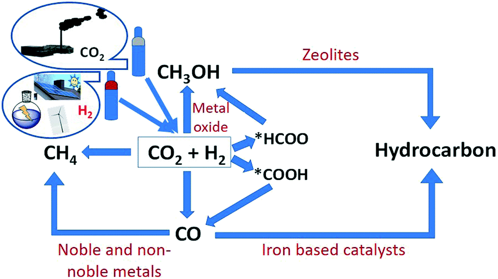 | ||
| Fig. 1 Pictorial representation of regeneration of CO2 to value-added products via hydrogenation. | ||
Carbon capture is the main technology to obtain CO2 from different sources before and after its release into the atmosphere. The captured CO2 can thereafter be either stored, i.e. carbon capture and storage (CCS), or utilized further in carbon capture and utilization (CCU). Pre-combustion, post-combustion, and oxyfuel combustion are the three main CO2 capture systems related to different combustion processes.8,9 Out of them, the post-combustion technology offers a way to capture CO2 from flue gases that come from the combustion of fossil fuels. There are many separation technologies such as wet scrubbing, dry regenerable adsorption, membrane separation, cryogenic distillation, pressure and temperature swing adsorption that can be used to isolate CO2 from flue gases.8 CCS could face many challenges concerning transportation and storage of CO2, as there is a possibility for leakage and contamination of groundwater if geological storage is used.10
The utilization of CO2 after capturing is an attractive way to mitigate CO2 emissions. There are several processes where CO2 can be utilized such as enhanced oil recovery,11 mineralization,12 and conversion into value-added chemicals and fuels.13 However, CCU needs a large amount of energy for the conversion of CO2 due to its kinetic inertness and thermodynamic stability, but it could function as a part of the sustainable natural carbon cycle in the biosphere, if the cost of the produced materials is equal to the cost of their production as well as possible offset costs for emissions while reducing the excess CO2 emitted into the atmosphere.14 The second main reagent for CO2 transformation is hydrogen. Hydrogen itself is a renewable source of energy if it is produced from water splitting and using electricity from resources like wind, hydro and solar at low cost15 but its handling, storage, and transportation are challenging, considering its explosiveness and low-energy density. It is therefore a large advantage to use hydrogen for the reduction of CO2 and in this way to store energy in the form of chemicals and fuels, which are easier to store and transport. Therefore, the current focus of this review is the production of chemicals like CH3OH (methanol) and value-added hydrocarbons such as lower olefins, gasoline, aromatics and petroleum gas from the hydrogenation (HYD) of CO2.
The hydrocarbon synthesis could be possible via direct and indirect routes (Scheme 1).16
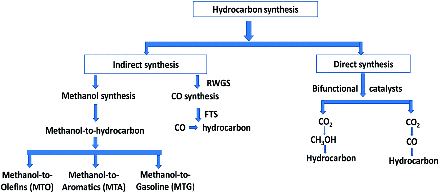 | ||
| Scheme 1 A schematic overview of hydrocarbon synthesis. | ||
1. Indirect CO2 hydrogenation to hydrocarbons
2. Direct CO2 hydrogenation to hydrocarbons
There are two main routes in indirect synthesis of hydrocarbons from CO2 which are (i) synthesis of CH3OH and subsequent transformation into hydrocarbons (olefins, gasolines, aromatics, alkanes, and so on) in different stages and (ii) synthesis of CO via reverse water gas shift (RWGS) and then formation of hydrocarbons using a modified Fischer–Tropsch synthesis (FTS) process based on two reactor stages. Hydrocarbons can be synthesized by a direct route which could be more economically favourable and environmentally benign compared to indirect routes.17,18 The direct route also includes two routes: (i) hydrocarbon synthesis over bifunctional catalysts in which CO2 is first hydrogenated into CH3OH and then hydrocarbon, and (ii) reduction of CO2 to CO via the RWGS reaction followed by hydrogenation of CO to hydrocarbons via FTS. There are various possible reactions between CO/CO2 and H2 (Scheme 2), which could occur during CO/CO2 hydrogenation.
 | ||
| Scheme 2 Possible reaction between CO/CO2 and H2. | ||
Some reviews have explored the catalytic hydrogenation of CO2 including various factors related to catalyst activity, selectivity and conversion of CO2.19–21 These reviews mainly focus on various aspects of CO2 hydrogenation over noble and non-noble metal catalysts.19–25 In this review, the objective is to focus on recent advances in CO2 hydrogenation to hydrocarbons via methanol as an intermediate. In recent studies, CO2 hydrogenation over bifunctional catalysts was found to be an efficient method to synthesize hydrocarbons. In addition, metal and metal oxide-based catalysts have been developed for the synthesis of CH3OH and hydrocarbons directly from CO2 reduction. Thus, this review includes these recent studies where hydrocarbons are synthesized directly from CO2 in a single step combining CO2 to methanol, and methanol to hydrocarbons reaction steps. The mechanisms, catalyst preparation methods, and proximity effects are discussed based on results from in situ experiments and DFT studies over bifunctional catalysts to understand the one-step process for the synthesis of hydrocarbons. To gain a flavor of how each process performs separately, detailed studies of CO2 to methanol and methanol to hydrocarbons are also discussed in this review. More specifically, for the methanol to hydrocarbons process, we review the process from the perspective of the CO2 to hydrocarbons process itself. Thus, the performance of catalysts in the presence of H2, CO2, and H2O (the reactants and byproducts of the direct conversion of CO2 to hydrocarbons process) is discussed in detail. Furthermore, this section also incorporates a review of the methanol to hydrocarbons process, reaction mechanism based on experimental evidence, shape selectivity, catalyst deactivation, and regeneration pathways for a better understanding of the direct conversion of CO2 to hydrocarbons process discussed in detail in the following section. In addition, this review also provides an outline of various aspects like catalyst synthesis, catalytic activity and reaction mechanisms from experiments, DFT calculations, and a kinetic modeling section discussing the reaction kinetics for the conversion of CO2 to methanol and methanol to hydrocarbons using advanced heterogeneous catalysts.
Thus, this review consists of four major sections which cover (1) CO2 to methanol, (2) methanol to hydrocarbons, (3) CO2 to hydrocarbons, and (4) kinetic modeling.
2. Indirect CO2 hydrogenation
A variety of chemicals such as CH3OH, dimethyl ether (DME), formic acid, ethanol, and hydrocarbons like methane, liquid fuels, aromatics and lower olefins are the products of CO2 hydrogenation. There are many reports and reviews on the synthesis of these products from CO2.24,26 For example, Yang et al. reported the catalytic hydrogenation of CO2 to value-added hydrocarbons.20 Recently, Li et al. reviewed the recent advances in CO2 hydrogenation to CH4 and C2+ hydrocarbons over Ni, Co, Ru, Ir, Fe and Rh catalysts and discussed the metal–support interaction, effect of metal particle size, process integration, reaction mechanism, and catalyst deactivation during CO2 hydrogenation.27 This review section covers the indirect route of CO2 hydrogenation into hydrocarbons which includes (1) CO2 hydrogenation to CH3OH and (2) CH3OH to hydrocarbons (MTH). A detailed study of catalyst performance and reaction mechanisms is discussed below.2.1 CO2 hydrogenation to CH3OH
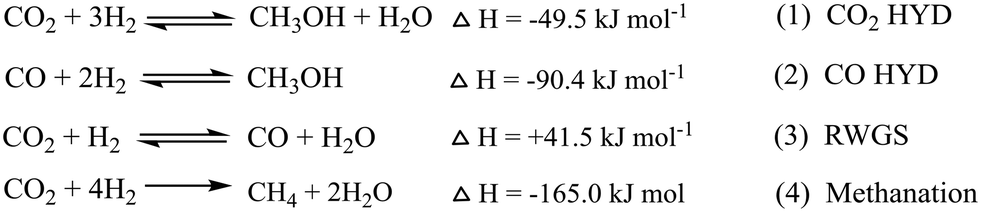
This section gives an overview of the various reports on CH3OH synthesis (Table 1). Methanol has been synthesized by heterogeneous and homogeneous catalysis, as well as electrochemical and photocatalytic processes.28–34 In earlier studies, syngas was the main source for the production of CH3OH as it can be produced from various sources such as biomass, natural gas, coal, and wastes, but in recent studies, CO2 transformation into value added chemicals is found to be an important theme to use surplus CO2 present in the environment. The main chemical reactions include direct CO2 hydrogenation to CH3OH according to:CO2 + 3H2 ⇌ CH3OH + H2O, ΔH298K = −49.5![[thin space (1/6-em)]](https://www.rsc.org/images/entities/char_2009.gif) kJmol−1 kJmol−1 | (5) |
| CO2 + H2 ⇌ CO + H2O, ΔH298K = 41.5kJmol−1 | (6) |
| Catalysts | P (MPa) | Preparation method | T (K) | GHSV (h−1) | CO2 conv. (%) | CH3OH select. (%) | Ref. |
|---|---|---|---|---|---|---|---|
| na = not available. | |||||||
| Cu/ZrO2 | 1.7 | Co-precipitation | 493 | — | 6.0 | 67.0 | 46 |
| Cu–ZnO | 5 | Co-precipitation | 523 | — | 11.7 | 36.1 | 51 |
| Cu/ZnO/Al2O3 | 4.9 | Co-precipitation | 523 | — | 19.7 | 48.1 | 47 |
| Cu/ZrO2 | 1.7 | Sequential precipitation | 623 | — | 6.9 | 70.0 | 48 |
| Cu/ZrO2 | 2 | Deposition–precipitation | 513 | 5400 | 6.3 | 48.8 | 64 |
| Cu/Zn/Ga/SiO2 | 2 | Co-precipitation | 543 | — | 5.6 | 99.5 | 83 |
| Cu/Ga/ZnO | 2 | Co-precipitation | 543 | — | 6.0 | 88.0 | 84 |
| Cu/YDC/γ-Al2O3 | 3 | Co-precipitation | 523 | — | na | 78.6 | 87 |
| Cu/ZnO/ZnO | 2 | Gel co-precipitation | 513 | 7200 | 17.3 | 32.4 | 88 |
| Cu–ZnO–ZrO2 | 8 | Co-precipitation | 493 | 3300 | 21.0 | 68.0 | 81 |
| Mn–Cu/Zn/ZrO2 | 10 | Thermal decomposition | 553 | 3400 | 16.0 | 91.0 | 85 |
| Cu/Ga/ZrO2 | 2 | Deposition–precipitation | 523 | 2500 | 13.7 | 75.5 | 86 |
| Cu/B/ZrO2 | 2 | Deposition–precipitation | 523 | 2500 | 15.8 | 67.2 | 86 |
| Cu/Zn/Ga/ZrO2 | 8 | Co-precipitation | 523 | 3300 | na | 75.0 | 55 |
| Cu/Zn/Al/ZrO2 | 4 | Co-precipitation | 513 | 9742 | 18.7 | 47.2 | 89 |
| Cu–ZnO–Al2O3 | 5 | Co-precipitation | 443 | — | 14.3 | 54.8 | 90 |
| Cu–ZnO–ZrO2 | 1.0–3.0 | Co-precipitation | 473 | 8800 | 5.8 | 55.2 | 91 |
| Cu–ZnO–ZrO2 | 3 | Co-precipitation | 503 | — | 15.2 | 35.1 | 82 |
| Cu/Zn/ZrO2 | 3 | Co-precipitation | 523 | — | 19.4 | 29.3 | 82 |
| Cu/Zn/ZrO2 | 3 | Urea–nitrate combustion | 513 | 3600 | 17.0 | 56.2 | 92 |
| Cu/Zn/ZrO2 | 3 | Glycine–nitrate combustion | 493 | 3600 | 12.0 | 71.1 | 93 |
| Cu/plate ZnO/Al2O3 | 4.5 | Precipitation | 543 | — | 10.9 | 72.7 | 69 |
| Cu/Ga2O3/ZrO2 | 3 | Ion exchange/impregnation | 523 | 20000 |
1.3 | 74.0 | 54 |
| Cu/Al2O3 | 95 | Impregnation | 553 | 11900–25000 |
30.0 | 80.0 | 78 |
| Cu–ZnO–ZrO2 | 4 | Co-precipitation | 513 | 4000 | na | na | 94 |
| Cu–ZnO–Al2O3 | 36 | Co-precipitation | 533 | 10471 |
65.8 | 77.3 | 79 |
| Cu/ZnO/Al2O3 | 3 | Co-precipitation | 503 | — | 18.3 | 43.0 | 80 |
| Cu/ZnO/ZrO2/Al2O3 | 3 | Co-precipitation | 503 | — | 23.2 | 60.3 | 80 |
| Cu–ZnO–ZrO2 | 3 | Co-precipitation | 513 | 3600 | 12.1 | 54.1 | 95 |
| Cu–ZnO–ZrO2 | 5 | Co-precipitation | 553 | 10000 |
23.0 | 33.0 | 96 |
| Cu/ZrO2 | 3 | Impregnation | 553 | — | 12.0 | 32.0 | 97 |
| Cu/ZrO2 | 0.1 | Deposition–precipitation | 493 | — | 0.53 | 19.8 | 98 |
| Cu–ZnO–ZrO2 | 5 | Co-precipitation | 553 | 10000 |
21.0 | 34.0 | 99 |
| Cu–ZnO–Al2O3 | 44.2 | Co-precipitation | 553 | 10000 |
65.3 | 91.9 | 77 |
| Cu–ZnO–ZrO2 | 3.9 | Co-precipitation | 473 | 7800 | 3.9 | 70.0 | 100 |
| Pd/SiO2 | 0.95 | Incipient wetness | 548 | — | 0.8 | 9.5 | 49 |
| Pd/CeO2 | 3 | Impregnation | 533 | — | 5.2 | 84.7 | 50 |
| Pd/SiO2 | 5 | Co-precipitation | 523 | — | 0.05 | 100 | 51 |
| Pd/Ga2O3 | 5 | Co-precipitation | 523 | — | 19.6 | 51.5 | 51 |
| PdZn/h-CNTs | 3 | Impregnation | 523 | 1800 | na | 99.6 | 101 |
| Pd/β-Ga2O3 | 3 | Incipient impregnation | 523 | — | 0.9 | 52.0 | 102 |
| PdGa/(β-Ga2O3) | 0.7 | Incipient wetness impregnation | 523 | — | ≤1 | 5.2 | 103 |
| Pd/plate Ga2O3 | 5 | Deposition | 523 | — | 17.3 | 51.6 | 104 |
| PdGa/(rod-Ga2O3) | 5 | Impregnation | 523 | — | 11.0 | 41.3 | 105 |
| Pd–Cu/SiO2 | 4.1 | Impregnation | 573 | 3600 | 6.6 | 34.0 | 52 |
| Pd/ZnO | 2 | Sol-immobilization | 523 | — | 10.7 | 60.0 | 106 |
| PdZnAl/hydrotalcite | 3 | Co-precipitation | 523 | — | 0.6 | 60.0 | 107 |
| Au/ZnO/ZrO2 | 8 | Co-precipitation | 493 | 3300 | 1.5 | 100 | 81 |
| Au/Cu–ZnO–Al2O3 | 1–6 | Co-precipitation | 533 | 7000–13200 |
28.0 | 55.0 | 56 |
| Au/ZnO | 0.5 | Deposition–precipitation | 493 | — | 0.2 | 56.2 | 108 |
| Au/ZnO | 0.5 | Deposition–precipitation | 513 | — | 1.0 | 70.0 | 109 |
| Ni5Ga3/SiO2 | 1 | Impregnation | 483 | 6000 | na | na | 110 |
| PtW/SiO2 | 3 | Impregnation | 473 | — | 2.6 | 92.2 | 111 |
| Re/ZrO2 | 1 | Impregnation | 433 | — | na | 73.2 | 112 |
| Rh/TiO2 | 1 | Impregnation | 513 | 2400 | na | 60.7 | 113 |
| Rh/SiO2 | 5 | Impregnation | 473 | — | 0.5 | 6.8 | 114 |
| Rh/TiO2 | 2 | Incipient wetness impregnation | 543 | 3000–6000 | 7.9 | 0.8 | 53 |
| Rh–Fe/TiO2 | 2 | Incipient wetness impregnation | 543 | 3000–6000 | 9.2 | 1.2 | 53 |
| Ag/ZnO/ZrO2 | 8 | Co-precipitation | 493 | 3300 | 2.0 | 97.0 | 81 |
| La–Zr–Cu–ZnO | 5 | Sol–gel | 523 | 3600 | 13.0 | 52.5 | 115 |
From the above chemical reaction, it can be seen that CH3OH synthesis from CO2 and the direction of the reaction depends upon temperature, pressure and reactant ratio as the CO2 hydrogenation to CH3OH reaction is exothermic (eqn (5)), whereas the competitive RWGS reaction is endothermic (eqn (6)). Generally, a lower reaction temperature and higher reaction pressure favor the synthesis of CH3OH. However, a high reaction temperature is helpful for CO2 activation whereas the lower temperature is thermodynamically favorable for CH3OH formation and this condition may create a kinetic limitation for the reaction. Under the reaction conditions, there are other competing reactions that occur in addition to RWGS that can produce many side products like methane, formaldehyde, and formic acid.32 The water vapor and other side products inhibit the reaction and may cause catalyst deactivation.35–37 To avoid the formation of side products and increase the stability of the catalyst, an efficient catalyst system is required.
Cu/ZnO/Al2O3 catalysts have been used and studied for the synthesis of CH3OH from syngas at the industrial scale while at the laboratory scale, the Cu–ZnO system with various support materials has been studied extensively for CH3OH synthesis.38–40 A number of research groups have developed a wide variety of heterogeneous catalysts for the synthesis of CH3OH from CO2 hydrogenation. There are various reports in which Cu, Pd, Ag and Pt have been used as active catalysts and as promotors, and oxygen-deficient materials like In2O3 have been employed as active catalysts.41–44
At the industrial scale, BASF was the first to produce CH3OH from syngas.57,58 The Cu/ZnO/Al2O3 catalyst, which was developed by ICI (Imperial Chemical Industries), allowed for industrial operation under milder reaction conditions.59–61 In many reports, Cu has been used as an active catalyst and later it was modified with other metals and non-metal promoters. Activity and selectivity for CO2 hydrogenation over Cu alone were not enough for large scale CH3OH synthesis; thus appropriate changes were made to increase the activity and selectivity of catalysts.62,63 No doubt, the achievable activity and selectivity depend on other factors as well like the catalyst composition, catalyst preparation method and reaction conditions which also affect the surface structure of the catalyst.64 ZnO has been found to be most preferably combined with Cu, as it facilitates the dispersion and stability of the active Cu sites by providing a close contact between itself and the Cu phase.23,25,65 The interface between Cu and ZnO plays a crucial role in preparing a highly active catalyst and it can be optimized by various factors like temperature, hydrogen partial pressure, and heating rate.66,67 In addition, the exposed phase of ZnO which is in contact with Cu regulates the catalytic activity of the Cu/ZnO system.68,69 Lei et al. studied the morphology effect of ZnO and found that the (002) face of ZnO gave good results in CH3OH synthesis due to its higher concentration of oxygen vacancies.68 Several efforts have been made to increase the activity of the Cu/ZnO system by fabricating new structures of the catalyst like a core–shell design of Cu–ZnO, graphitic-like ZnO and nano-alloy layers of Cu–Zn.66,67,70,71 Further, Cu/ZnO-based catalysts have been modified with promotors and stabilizers to increase the activity and stability.72,73 Later, it has been reported that the addition of Al2O3 increases the stabilization of the Cu active site.74 Another method to increase activity is to focus on the synthesis process. The conventional synthesis process for Cu/ZnO/Al2O3 is co-precipitation in which the synthesis of hydroxycarbonates of Cu, Zn and Al2O3 is a crucial stage. This stage can alter the surface area of Cu and the interaction between ZnO and Cu that are the important factors to define/change the activity of the catalysts.29,75 The synthesis of the hydroxycarbonates can be controlled by pH, temperature and precipitate washing.76
Gaikwad et al. studied the effect of pressure, temperature, and GHSV (gas hourly space velocity) on CO2 hydrogenation to CH3OH over a commercial Cu/ZnO/Al2O3 catalyst.77 Excellent results were observed at 44.2 MPa with a low GHSV in the range of 533–553 K (Table 1). In this study, the authors achieved the highest CH3OH selectivity compared to the other Cu/ZnO/Al2O3-based studies mentioned in Table 1 along with high CO2 conversion. Cu/Al2O3 has also been screened for CH3OH synthesis at 95 MPa to get a higher product yield and CO2 conversion.78 Tidona et al. reported a higher space-time yield at 95 MPa compared to 3 MPa.78 In both studies, it can be noted though that the extreme pressures which are thermodynamically favorable played an important role in obtaining higher conversion and selectivity rather than the catalyst performance. To get higher CH3OH selectivity, Bansode and Urakawa reported the effect of high H2 partial pressure by decreasing the molar ratio of CO2/H2 from 1:3 to 1:10 and they found good CH3OH selectivity and CO2 conversion with excess CO2.79 Li et al. doped Zr into commercial Cu/ZnO/Al2O3 catalysts and studied the activity, stability and poisoning effect of water on the active sites of the catalysts.80 The authors found excellent performance for the Zr-doped catalyst compared to the commercial catalyst with excellent tolerance for water vapor. Considering the positive effect of Zr in CO2 hydrogenation, Al2O3 has been replaced with ZrO2 in recent years. Słoczyński et al. synthesized a series of catalysts in which crystalline ZnO and amorphous ZrO2 were co-precipitated with Cu, Ag, and Au.81 The Cu-containing ZnO/ZrO2 catalyst exhibited higher activity than Ag and Au. The effect of suspension ageing on a co-precipitated Cu/ZnO/ZrO2 catalyst was studied by Raudaskoski et al. and as a result, they found higher CO2 conversion and selectivity to CH3OH with increasing ageing time. With a longer ageing time, a fine crystallite structure of the catalyst was obtained with a high surface area and less sodium content as Na2CO3 was used as the precipitating agent. The longer ageing time also helped in the reduction of Cu.82
In addition, different modifiers are used to increase the activity and stability of the Cu-based system. Toyir et al. prepared a Ga-promoted Cu-based system in which SiO2 and ZnO were used as supports. The hydrophilic nature of SiO2 along with smaller particles of Ga2O3 enhanced the catalytic activity. The hydrophilic support increased the dispersion of the catalyst whereas the small Ga2O3 particles favor the formation of Cu+.83 Further, the same group studied the influence of metallic precursors on the catalytic performance of the Ga-promoted Cu-based system and found that the use of methanolic solutions of methoxide–acetic acid precursors in the Ga-promoted catalyst preparation played a key role in obtaining a high performance catalyst in CO2 hydrogenation to CH3OH.84 Lachowska and Skrzypek investigated the effect of Mn as a promoter on Cu/Zn/Zr systems.85 Later from the same group, Słoczyński et al. studied the effect of metal and metal oxides (Mn, B, In, Ga, Gd, Y, and Mg oxides) on the stability and activity of Cu/ZnO/ZrO2 systems.55 Among the various oxides, the Ga2O3 additive with the catalyst gave the highest CH3OH selectivity. Liu et al. prepared Cu/Ga2O3/ZrO2 and CuO/B2O3/ZrO2 catalysts and in this study, they discussed the effect of the nanocrystalline Zr size on the catalytic performance.86 It was observed that the nanocrystalline Zr changed various properties of the catalyst such as the electronic structure and the interaction between the metal and support, leading to more corner defects, facile reduction, and more oxygen vacancies on the surface, and all these changes were found to be beneficial for CH3OH synthesis. Fornero et al. synthesized Cu–GaOx/ZrO2 catalysts and observed higher CH3OH selectivity with a high Ga/Cu atomic ratio.54 Besides Cu, other transition metals have been used for CH3OH synthesis. In the literature, Pd-based catalysts are the most commonly studied for hydrogenation of CO2 to CH3OH after Cu. Erdöhelyi et al. reported various Pd-based catalysts supported on SiO2, TiO2, Al2O3, and MgO and concentrated on the surface species during the reaction.49 It was observed that the dispersion of Pd plays an important role in controlling the direction of the CO2 + H2 reaction. Pd catalysts supported on CeO2, SiO2, Ga2O3 and carbon nanotubes (CNTs) were used for CH3OH synthesis.50,51 Bahruji et al. prepared Pd/ZnO catalysts by different methods and screened them for hydrogenation of CO2. Their study includes the structure–activity relationship and they found the PdZn alloy to be the active site, where a high surface area, smaller alloy size, and less metallic Pd surface are favorable conditions to increase the selectivity for CH3OH.106 Liang et al. developed PdZn alloys supported on multiwalled CNT catalysts for CH3OH synthesis where CNTs function as a promoter and catalyst support.101 Pd–ZnO/CNT catalysts were successful in providing a micro-environment with a higher concentration of active H-adspecies at the surface, whereas herringbone-type CNTs helped in the promotion of the catalysts.
Collins et al. studied Ga2O3 supported Pd catalysts and explained the function of Ga2O3 and Pd.102 It is proposed in this catalytic system that gallium oxide provides a surface for adsorption of CO2 as carbonate species and Pd dissociates the hydrogen molecule to hydrogen atoms that spillover to the oxide surface converting the adsorbed carbonate to formate species. Further, the same function and interaction between Pd and Ga were identified using quasi-in situ transmission electron microscopy by the same group.103 The effect of the shape of Ga2O3 on interactions was explained by Zhou et al., where the (002) surface of Ga2O3 was found to be highly unstable, which readily provided more O-defect sites and electrons in the conduction band than other surfaces. It gave higher metal dispersion that led to the formation of PdGax which was found to be more active for CH3OH production.104,105 In another metal series, Ni, Rh, Re, and Pt have been used for CH3OH selectivity as they have higher activity towards the hydrogenation reaction.53,112,113 Studt et al. explored the activity of Ni-based alloys (NiGa, Ni3Ga and Ni5Ga3) for hydrogenation of CO2 at ambient pressure.110 Importantly, these alloys were superior to the Cu/ZnO/Al2O3 catalyst due to their ability to reduce the RWGS activity and favor CH3OH production.116,117 The structure effect of the alloys on the reaction was studied by Sharafutdinov et al.,118 where a series of Ni–Ga catalysts were prepared with different compositions. Later, the catalysts were screened, and it was found that the reactivity depended on the catalysts' intermediate phase, particle size or structure. The Ni5Ga3 composition was found to be more active for CH3OH selectivity among the various compositions.110
Many studies have reported the high reactivity of Au and Ag towards CH3OH selectivity.81,108,119 Hartadi et al. studied the pressure and CO effect over Au/ZnO catalysts and observed that high temperature and pressure inhibit the activity of the RWGS reaction and improve the product selectivity, whereas an increase in the CO concentration decreases the formation of CH3OH.119 Słoczyński et al. prepared Au and Ag-based catalysts with a support composition of 3ZnO–ZrO2 and studied the morphology, surface composition and activity of the catalysts for CH3OH synthesis from CO2.81 In the Au–Cu/ZnO/Al2O3 system, the hydrogen spillover on the Au–Cu surface reduced the reaction selectivity towards CO.56 Hartadi et al. reported about various Au supported catalysts (Au/Al2O3, Au/ZnO, Au/TiO2, and Au/ZrO2) and studied their activity for CH3OH synthesis.108 The Au/ZnO system was found to be more selective for CH3OH synthesis and the authors extended this study to examine the effect of the catalyst size, total pressure, support, and influence of CO on the reaction activity.119
Frauenheim and Xiao reported first principles calculations for CO2 hydrogenation on the ZnO supported Ag (111) monolayer.120 The CO2 adsorption on the pristine and stretched surface of Ag (111) was weak and the ZnO support increased the binding ability of CO2 and catalytic activity due to a strong metal–support interaction. Furthermore, the phase diagram for the Ag-doped ZnO surface was investigated under hydrogen and oxygen atmospheres and found stable in a hydrogen atmosphere. Also, the Zn impurities do not affect the reactivity for CO2 adsorption and reduction.
2.1.1.1 Reaction intermediates and mechanism over Cu-based systems. Since many reports are based on Cu-based systems, the reaction mechanism has been more explored on Cu-containing catalysts by means of experiments, analytical techniques, and DFT calculations.89,121–124 Many studies have reported two key intermediates formed during the synthesis of CH3OH.125,126 Some research groups found the formate (HCOO*) intermediate127,128 whereas others the hydrocarboxyl species (COOH*) on the surface of the catalysts. These intermediate species divide the mechanism into two routes: (1) formate route and (2) hydrocarboxyl route.129,130Scheme 3 below illustrates different possible reaction intermediates and steps during the hydrogenation of CO and CO2 into CH3OH over Cu.131 Here, we will only elaborate on the intermediates that formed during CO2 hydrogenation. Nakatsuji and Hu explained the formation of formate on Cu (100) and Zn/Cu (100) surfaces employing ab initio calculations and found that CO2 reacts with surface hydrogen to form formate via either a Langmuir–Hinshelwood (LH) or an Eley–Rideal (ER) mechanism.132 In the formate route, first CO2 reacts with atomic hydrogen to form HCOO*. Further, this species again hydrogenates to HCOOH* (ref. 63) which is further hydrogenated making H2COOH* followed by cleavage into H2CO* and *OH. Further, the subsequent hydrogenation of this species forms H3COH. In the above route, the first atomic hydrogen attached with carbon (HCOO*) and the second hydrogen has two ways to attach: (A) it could attach again to carbon and form H2COO* (ref. 40) and (B) it could bind with oxygen to make HCOOH* (ref. 133) which further could take hydrogen on the carbon atom whereas H2COO* could take hydrogen on the oxygen atom before cleavage. Larmier et al. determined the surface intermediates on the surface of Cu–ZrO2 using kinetics, in situ IR, NMR, and DFT.121 The combined results showed the formation of the HCOO* intermediate and the Cu–ZrO2 interface plays a crucial role in converting HCOO* to CH3OH. Kattel et al. identified the same intermediate by kinetic Monte Carlo simulations, DFT, and X-ray photoemission spectroscopy (XPS) on the Cu–ZnO synergic interface.129
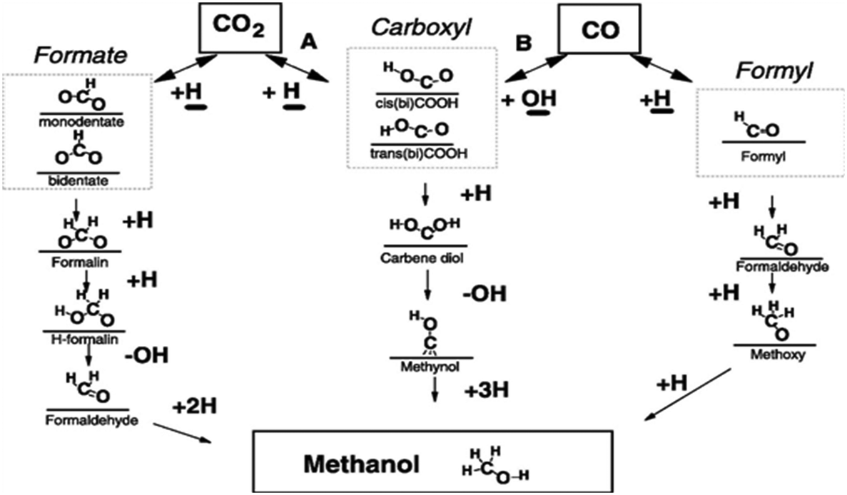 | ||
| Scheme 3 Mechanistic pathways for conversion of CO and CO2 to CH3OH over Cu. Reprinted from J. Catal., 298, Y. Yang, C. A. Mims, D. Mei, C. H. Peden and C. T. Campbell, Mechanistic studies of methanol synthesis over Cu from CO/CO2/H2/H2O mixtures: the source of C in methanol and the role of water, page no. 10–17, Copyright (2013), with permission from Elsevier. | ||
The second route favors the first attachment of atomic hydrogen with an oxygen of the CO2 molecule rather than carbon to form *COOH. Further, the second atomic hydrogen also binds with the second oxygen of CO2 followed by the formation of *OH and *COH. Then the third, fourth and fifth hydrogen atoms bond with carbon to finally yield CH3OH.126 In this route, there is one more possibility for successive hydrogenation. In this possible alternative, *COOH (cis-COOH) first dissociates into CO and OH and a further hydrogen atom binds with carbon to form methoxy which then forms CH3OH by the addition of hydrogen with oxygen. This intermediate was observed on Cu (111) and proposed based on a DFT study. The authors claimed based on their DFT calculations that CO2 hydrogenation to methanol on Cu (111) via the hydrocarboxyl (trans-COOH) intermediate is kinetically more favorable than formate in the presence of H2O via a unique hydrogen transfer mechanism. It was reported that the formate intermediate on Cu (111) is not feasible due to the high activation barriers for some of the elementary steps.126
Instead of the above two intermediates, Grabow et al. presented a model for CH3OH synthesis that includes reaction intermediates such as hydroxymethoxy (CH3O2) and formic acid (HCOOH) on a commercial Cu/ZnO/Al2O3 catalyst.133
| Catalysts | Preparation method | T (K) | P (MPa) | GHSV (h−1) | CO2 conv. (%) | CH3OH select. (%) | Ref. |
|---|---|---|---|---|---|---|---|
| na = not available. | |||||||
| In2O3 | Calcination | 543/603 | 4 | 15000 |
1.1/7.1 | 54.9/39.7 | 44 |
| In2O3/ZrO2 | Impregnation | 573 | 5 | 16000 |
5.2 | 99.8 | 142 |
| ZnO–ZrO2 | Co-precipitation | 588 | 5 | 24000 |
>10 | 91.0 | 147 |
| Pd/In2O3 | Incipient wetness impregnation | 573 | 5 | >21000 |
>20 | >70 | 146 |
| Pd–P/In2O3 | Impregnation | 498/573 | 5 | — | 3/20 | 6.01/27.81 | 146 |
| In5/ZrO2 | Impregnation | 553 | 5 | 24000 |
na | 60.0 | 143 |
| Cu–In–Zr–O | Co-precipitation | 523 | 2.5 | 18000 |
1.48 | 79.7 | 148 |
| Ga0.4In2–xO3 | Co-precipitation | 593 | 3 | — | 12.5 | 26.4 | 149 |
| In:Pd (2:1)/SiO2 |
Incipient wetness impregnation | 573 | 5 | — | na | 61.0 | 150 |
| Pd–In2O3 | Co-precipitation | 553 | 5 | — | na | 78.0 | 151 |
| Pt/In2O3 | Impregnation | 303 | 0.1 | — | 37.0 | 62.6 | 152 |
| Pd/In2O3/SBA-15 | Wetness impregnation | 533 | 4 | — | 12.6 | 83.9 | 153 |
Luo et al. developed a porous 3D hierarchical indium-based catalyst for selective CO2 reduction via electrodeposition and they showed that it exhibits an extremely high HCOO production rate and excellent selectivity with high stability.144 The reduction of CO2 to formate is explained by DFT calculations. In this study, Pd/In-nano particles (NP) having different compositions were screened in the liquid phase hydrogenation of CO2 and they were found to have higher CH3OH synthesis activity than Cu/ZnO/Al2O3, Pd (0) and In2O3. Microkinetic modeling and DFT calculations were conducted to examine the reaction mechanism on the Pd4/In2O3 catalyst.145 They found that the strong interaction between In2O3 and Pd occurs during reduction and forms bimetallic species that change the nature of interfacial sites which were found detrimental to CH3OH synthesis. Later, Rui et al. used a Pd loaded In2O3 catalyst for CH3OH synthesis in which they used a Pd–peptide composite to prevent the formation of Pd–In bimetallic species during mixing with In2O3.146 The peptide templates bond to Pd ions through electrostatic interaction between peptide sites (negative charge) and Pd2+, which control the facet and size of catalysts under mild conditions. After confinement of Pd NPs on In2O3, the peptide composite was removed by thermal treatment. Recently, Frei et al. reported a different method to stop the formation of Pd–In bimetallic species, in which the Pd clusters were anchored on the In2O3 lattice by coprecipitation and stabilized by Pd atoms which were embedded into the In2O3 matrix.151 This preparation method helped to modify the electronic properties of the catalyst which increased the formation and dispersion of Pd atoms. The CH3OH formation rate on this catalyst was found to be higher than Pd–P/In2O3.146 García-Trenco et al. prepared unsupported PdIn (Pd:In = 1:1) intermetallic nanoparticles using a thermal decomposition method for liquid phase CH3OH synthesis under the reaction conditions of 5 MPa at 483 K with a ratio of 3:1 of H2:CO2.42 The catalyst exhibited around 70% higher CH3OH rates and higher stability than the conventional Cu/ZnO/Al2O3 catalyst. Recently, the promotional effect of Pd on the In2O3 catalyst was investigated using in situ X-ray spectroscopy, microkinetic modeling, and ex situ characterization.150 Silica (SiO2) supported catalysts were prepared and tested for CH3OH synthesis by varying In:Pd ratios on SiO2 (0:1, 1:0, 1:1, 2:1, 1:2). Out of the various catalysts, the In:Pd catalyst having a 1:2 ratio on SiO2 showed the highest activity and selectivity towards CH3OH. It was observed from characterization that the catalyst has an In2O3 phase and In–Pd intermetallic compounds gave the highest CH3OH formation. Further, DFT and experimental results suggested that the active phases were formed due to the synergistic interaction between the In2O3 phase and a bimetallic In–Pd particle.
The authors found a similar composition–activity behavior in the case of In–Ni systems.150 Recently, Men et al. prepared Pt NP incorporating In2O3 catalysts for CH3OH synthesis using a dielectric barrier discharge plasma reactor.152 The catalyst presented good activity and selectivity to CH3OH at 303 K and 0.1 MPa. A composition of Cu–In–Zr–O was reported by Yao et al. to act as a bifunctional catalyst, where defective In2O3 adsorbs CO2 and Cu-sites adsorb and provide active hydrogen to adjacently adsorbed CO2.148 Commercial CH3OH synthesis occurs in a temperature range of 473–533 K but recently, Akkharaphattawon et al. reported CH3OH synthesis over GaxIn−xO3 at a higher temperature range (593–673 K).149 Fan's group reported various multiple-metal catalysts including In2O3, like Ni–In–Al/SiO2 and La–Ni–In–Al/SiO2 for the synthesis of CH3OH at low-pressure.154,155 Wang et al. synthesized a ZnO–ZrO2 catalyst for CH3OH synthesis which showed good CH3OH selectivity and sulfur resistance.147 In addition, the high CH3OH selectivity was due to the synergetic effect between Zr and Zn sites.
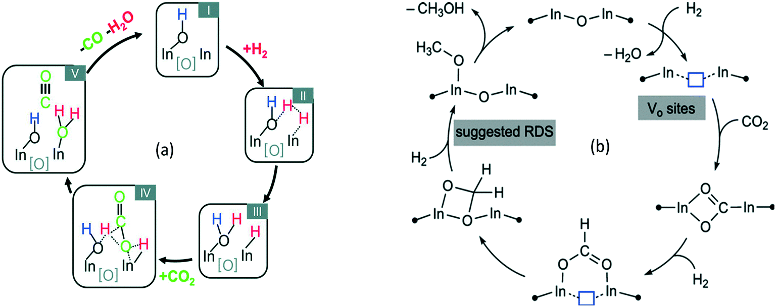
2.1.2.1 Reaction intermediates and mechanism over oxide-based catalysts. Before methanol synthesis, In2O3 and its composites have been studied for CH3OH steam reforming, dehydrogenation of propane156 and other chemical transformations.157–159 In this section, a plausible reaction mechanism based on DFT and in situ infrared Fourier transform spectroscopy DRIFT studies over In-based catalysts is discussed. Ghuman et al. investigated the role of surface hydroxy groups and oxygen vacancies in the photochemical and thermal reduction of CO2 to CO on In-based catalysts (Fig. 2a).160 The kinetic study, in situ spectroscopy, and DFT calculations showed that the oxygen vacancies and hydroxy groups both assist the RWGS reaction (Fig. 2a). The activation energy estimated for the RWGS reaction was 86 kJ mol−1 for photochemical reduction whereas it was 107 kJ mol−1 for thermal reduction. This study has opened a way to understand the surface conditions that can increase the activity of the catalyst towards the RWGS reaction, which is a concurrent reaction in the case of CH3OH synthesis. A similar activity towards the RWGS reaction was reported by other groups.137,138,161 Ye et al. investigated the adsorption and hydrogenation of CO2 on the (110) surface of In2O3via DFT calculations.140 Later, the same group found that the oxygen vacancy on the surface of In2O3 could act as an active site for CH3OH synthesis via computational modeling.141 A mechanism was proposed from various reports as shown in Fig. 2b by Tsoukalou et al.,162 in which oxygen vacancies termed as Vo sites were formed on the In2O3 surface. The presence of Vo sites was verified by various experiments based on electron paramagnetic resonance spectroscopy (EPR), X-ray photoelectron spectroscopy (XPS), and temperature-programmed desorption (CO2-TPD) of In2O3-based catalysts.140–142,159 These Vo sites assisted CO2 hydrogenation and activation by stabilizing the HCOO*, H2COO* and H2CO* species and the hydrogenation of H2CO* was found to be the rate determining step. It was observed that these sites could be recovered during hydrogenation of CO2. Later, Sun et al. experimentally confirmed the activity of In2O3 and reported 54.9% CH3OH selectivity at 543 K.44 It was observed that CO2 conversion increases and CH3OH selectivity decreases with rising temperature. Oxygen vacancies were found to be the active sites which were generated using thermal treatment or diluted hydrogen by the Pérez-Ramírez group.142 It was reported that thermally-induced oxygen vacancies had a higher CH3OH space time yield (STY) than H2-induced vacancies and it was found that hydrogen treatment reduced the surface area of In2O3. In addition, operando diffuse reflectance (DRIFTS) showed that adsorbed CO2 bridges with two In-atoms around thermally induced oxygen vacancies and hydrogenated intermediates formed thereof. The CH3OH selectivity was also increased by Cu addition to In2O3 where it was proposed that Cu helped to generate atomic hydrogen which was transferred to CO2 adsorbed on the surface of In2O3.148 In some reports, oxygen vacancy formation was increased by CO co-feeding and introducing Pd nanoparticles.142,145,146 Recently, a few reports discussed the positive synergetic effect between Pd and In for CH3OH synthesis.42,150 The adsorption, reactivity of hydrogen, defect formation, and bonding on different In2O3 samples were studied and as a result, the surface reduction, bonding of hydrogen, and formation of oxygen vacancies were observed after exposure to hydrogen at 573 K.163
 | ||
| Fig. 2 A proposed mechanism for (a) the CO2 + H2 → CO + H2O reaction on In2O3−x(OH)y. Reproduced from ref. 160 with permission from the Royal Society of Chemistry. (b) The hydrogenation of CO2 to CH3OH on Vo sites of In2O3. Reprinted (adapted) with permission from A. Tsoukalou, P. M. Abdala, D. Stoian, X. Huang, M.-G. Willinger, A. Fedorov and C. R. Müller, J. Am. Chem. Soc., 2019, 141, 13497–13505. Copyright (2019) American Chemical Society. | ||
A DFT study proposed a mechanism for CO2 hydrogenation on In2O3 where oxygen vacancies were created on the indium surface which aided the heterolytic cleavage of hydrogen. Further, the hydrogen atom was transferred to chemisorbed CO2 to start the hydrogenation and formation of various intermediates. According to this study, the route for CH3OH synthesis on In2O3 is shown below:140,141 (eqn (7))
| CO2 → *HCOO → *H2CO → *H3CO → CH3OH | (7) |
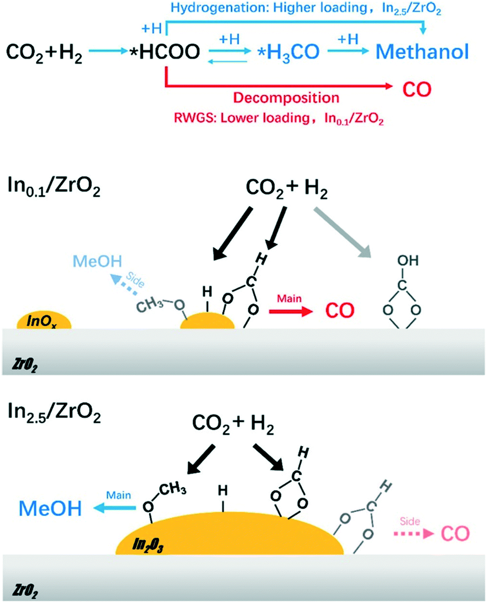 | ||
| Fig. 3 CO2 hydrogenation pathways and schematic–structure–performance relationships over Inx/ZrO2. Reprinted (adapted) with permission from T.-y. Chen, C. Cao, T.-b. Chen, X. Ding, H. Huang, L. Shen, X. Cao, M. Zhu, J. Xu and J. Gao, ACS Catal., 2019, 9, 8785–8797. Copyright (2019) American Chemical Society. | ||
2.2 Methanol to hydrocarbons (MTH)
One of the earliest discoveries of the conversion of methanol to hydrocarbons (MTH) was reported by Mobil researchers in the late 1970s.165,166 A zeolite-based catalyst (ZSM-5) was used for the reaction. This was then followed by the second oil crisis in 1979 which initiated extensive and systematic research on the conversion of methanol to hydrocarbon-range product molecules, eventually leading to the commissioning of a methanol to gasoline (MTG) plant by 1985 in New Zealand (14500 barrels per day).166,167 Methanol can also be utilized as the starting chemical for the synthesis of light olefins (methanol to olefins, MTO process), branched alkanes, aromatics (methanol to aromatics, MTA process), etc., generally designated as the methanol to hydrocarbons (MTH) process. The choice of a given product depends largely on the selection of catalyst and the operating conditions, usually in the temperature range of 623 to 773 K and atmospheric pressure. The selectivity to olefins increases with a decrease in pressure (kinetic effect) and an increase in temperature (partly thermodynamic). The conventional starting material for methanol is coal and natural gas; however, nowadays sustainable resources like biomass and CO2 are of increasing interest. Since the MTH process is a mature field of research, many excellent reviews are available in the literature covering the various aspects of the process including fundamental understanding, catalysts, structures, etc.168–173 Here we attempt to provide a description of the MTH process in the context of the direct conversion of CO2 to hydrocarbons (CTH process, both direct and indirect) as it represents an intermediate and final step of the CTH process itself. Therefore, in this section, we limit our focus to an introduction to the reaction mechanism of the MTH process as a preamble solely based on experimental evidence, shape selectivity of zeolites in the MTH reaction, and performance of catalysts and their deactivation trends in the presence of CO2, H2 and H2O as these molecules are involved in the CTH process. Moreover, a brief guide to the various approaches to regenerate the deactivated catalysts is also presented.
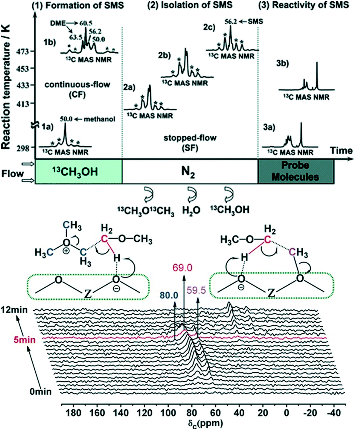
2.2.1.1 Experimental evidence for the first C–C bond formation mechanism. Brønsted acid sites on the zeolite catalyst are the active sites for the MTH process. The reaction initiates by the adsorption of methanol on these acid sites generating the surface methoxy species. The presence of these surface methoxy species has now been experimentally verified with the help of in situ MAS NMR spectroscopy (Fig. 4).174,175 The next step is the generation of trimethyl oxonium ions. These can be generated by the reaction of surface methoxy species/methanol with dimethyl ether, formed via the dehydration of two methanol molecules at the Brønsted acid sites. Wu et al.,176 with the help of the in situ solid-state 13C MAS NMR spectroscopic technique, identified the presence of trimethoxy oxonium species on the catalyst surface (Fig. 4 (bottom panel)). Both the surface methoxy species and trimethoxy oxonium species can act as potential methylating agents via the carbene ylide mechanism. They can methylate dimethyl ether with the help of the Lewis acidic surface oxygen atom of the zeolite framework to generate the first C–C bond, i.e., a surface adsorbed methoxyethane (Fig. 4 (bottom panel)). The methoxyethane's further transformation through the elimination of methanol generates the first C–C bond containing the ethene molecule. The surface methoxy species and trimethyl oxonium ion can also methylate methanol to form a surface adsorbed ethanol molecule, which upon further dehydration can also generate the ethene molecule.176
 | ||
| Fig. 4 Experimental evidence for surface methoxy species in different reaction environments (top panel), reprinted (adapted) with permission from W. Wang and M. Hunger, Acc. Chem. Res., 2008, 41, 895–904, Copyright (2008) American Chemical Society, and the first C–C bond formation route involving the trimethoxy oxonium species (bottom panel), Copyright (2017) Wiley, used with permission from X. Wu, S. Xu, W. Zhang, J. Huang, J. Li, B. Yu, Y. Wei and Z. Liu, Direct mechanism of the first carbon–carbon bond formation in the methanol-to-hydrocarbons process, Angew. Chem. Int. Ed., 2017, 56, 9039–9043, Wiley. 55, 15840–15845, Wiley. | ||
According to Li et al.,177 the mechanism of the first C–C bond formation over SAPO-34 occurs through the formation of the methoxymethyl cation intermediate (+CH2OCH3). The cation intermediate is formed from surface methoxy species and dimethyl ether. The methoxymethyl cation then reacts with another molecule of dimethyl ether or methanol to form 1,2-dimethoxyethane and 2-methoxyethanol, respectively, the compounds containing the first C–C bonds. The formation of the methyl cation was both theoretically and experimentally verified (Fig. 5).177
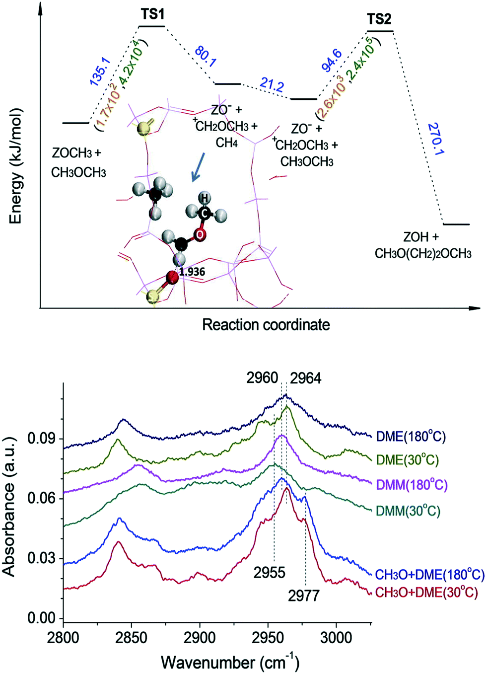 | ||
| Fig. 5 Theoretical (top panel) and experimental (bottom panel) evidence for the methoxymethyl cation route, the band at 2960 cm−1 is assigned to the CH2 group in CH3OCH2O-zeolite, DME = dimethyl ether, CH3O = surface methoxy species, DMM = dimethoxymethane. This article was published in Journal of Catalysis, J. Li, Z. Wei, Y. Chen, B. Jing, Y. He, M. Dong, H. Jiao, X. Li, Z. Qin, J. Wang, and W. Fan, A route to form initial hydrocarbon pool species in methanol conversion to olefins over zeolites, J. Catal., 2014, 317, 277–283, Copyright Elsevier (2014). | ||
Chowdhury et al.178 presented experimental (MAS NMR) evidence for the involvement of acetate species in the first C–C bond formation over the SAPO-34 catalyst. In the proposed mechanism, the surface methoxy species undergo carbonylation (CO being derived via the decomposition of methanol) to form a surface-bound acetate species (the first C–C bond) which upon addition of a methanol molecule generates a surface adsorbed methyl acetate species (Fig. 6).178
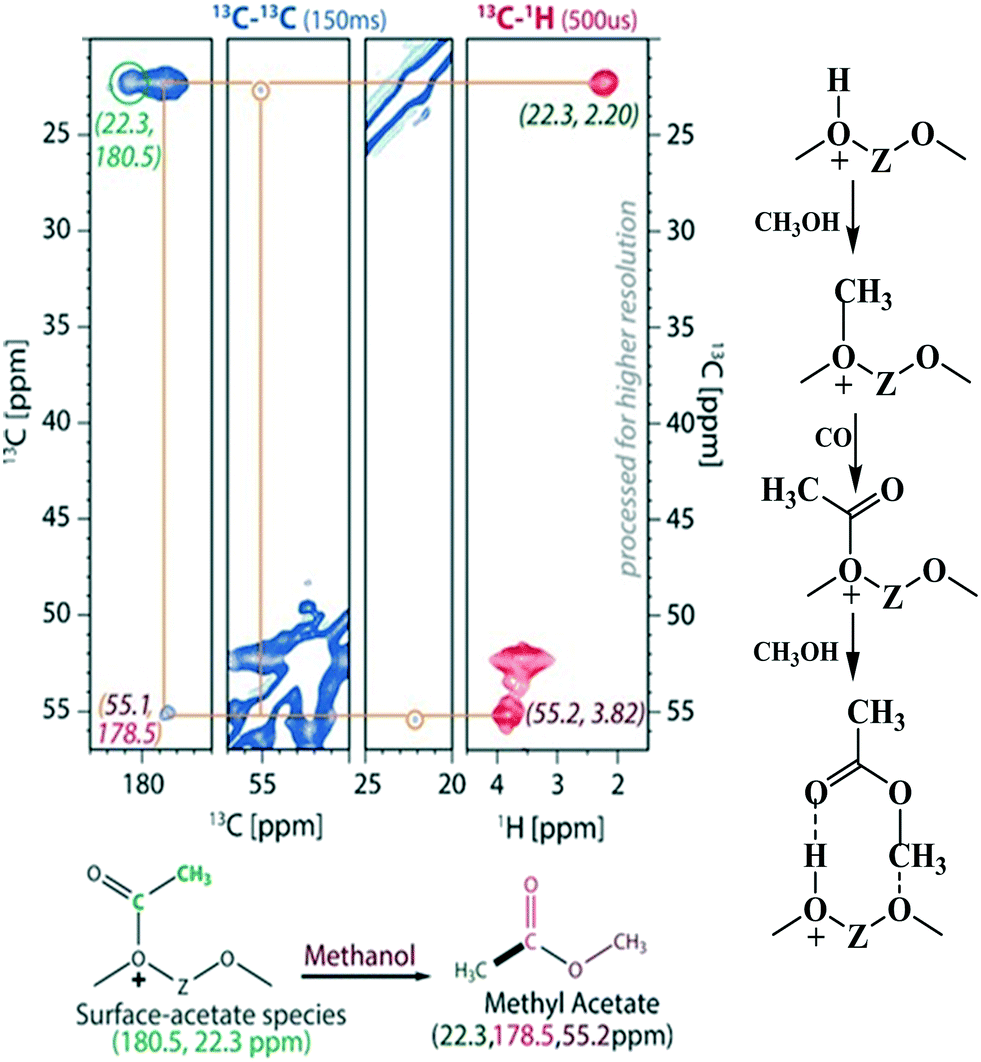 | ||
| Fig. 6 Experimental evidence for the acetate route and the reaction pathway for the first C–C bond formation involving acetate species, Copyright (2016) Wiley, used with permission from A. D. Chowdhury, K. Houben, G. T. Whiting, M. Mokhtar, A. M. Asiri, S. A. Al-Thabaiti, S. N. Basahel, M. Baldus and B. M. Weckhuysen, Initial carbon–carbon bond formation during the early stages of the methanol-to-olefin process proven by zeolite-trapped acetate and methyl acetate, Angew. Chem., Int. Ed., 2016, 55, 15840–15845, Wiley. | ||
2.2.1.2 Dual (arene and alkene) cycle mechanism – the hydrocarbon pool (HCP) mechanism. The dual cycle mechanism deals with the formation of reaction products (selectivity) after the first C–C bond formation. According to Dessau et al.,179 various aliphatic and aromatic hydrocarbons in the MTH reaction can be considered to generate through the consecutive methylation by methanol as shown in Fig. 7 (top left panel). In principle, ethylene is methylated to form propylene. Further methylation of propylene yields butylene and the process carries on generating higher hydrocarbons. Cyclization of the C6 alkenes and further methylation produces various substituted aromatics.
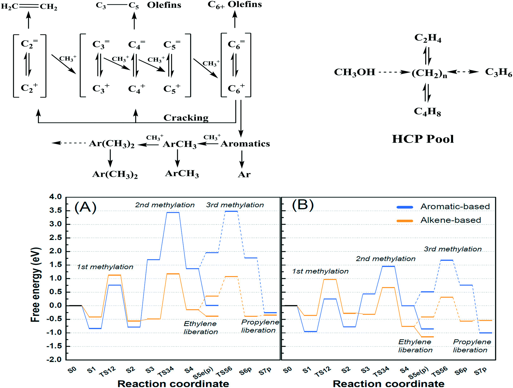 | ||
| Fig. 7 Top left panel: Consecutive methylation scheme for higher hydrocarbons, this article was published in Journal of Catalysis, R. Dessau and R. LaPierre, On the mechanism of methanol conversion to hydrocarbons over HZSM-5, 1982, 78, 136–141, Copyright Elsevier (1982). Top right panel: The HCP pathway, this article was published in Journal of Catalysis, I. M. Dahl and S. Kolboe, On the reaction mechanism for hydrocarbon formation from methanol over SAPO-34: I. Isotopic labeling studies of the co-reaction of ethene and methanol, J. Catal., 1994, 149, 458–464, Copyright Elsevier (1994). Bottom panel: Free energies of alkene- and aromatics-based MTO reactions at Al atoms situated at the straight channel – alpha position (A), and those situated at the channel intersection – beta position (B) of ZSM-5 zeolite,169 reprinted (adapted) with permission from S. Kim, G. Park, M. H. Woo, G. Kwak and S. K. Kim, ACS Catal., 2019, 9, 2880–2892, Copyright (2019) American Chemical Society. | ||
Dahl et al.180 used 13C labeled methanol and 12C labeled ethene over a SAPO-34 catalyst to verify the probable routes to higher hydrocarbon formation. The authors considered two mechanistic pathways; the first one was the previously suggested consecutive methylation path, and the second one was the “hydrocarbon pool” (HCP) type mechanism. The HCP is a pool of adsorbates having many characteristics similar to ordinary coke, represented as (CHx)n with 0 < x < 2. In the latter mechanism, methanol is continuously added to the pool of (CHx)n species, causing their growth. The (CHx)n species also undergo splitting/cracking to generate the product molecules (Fig. 7, top right panel). According to the experimental results (13C and 12C), only a minor part of propylene was formed from ethene and methanol, indicating that the HCP mechanism is more prevalent than the consecutive mechanism.
Arstad et al.181 also supported the HCP mechanism, suggesting that the reaction proceeds through penta- and hexamethyl benzene intermediates (the hydrocarbon pool). 13C labelled methanol and detailed analysis of the trapped molecules inside the SAPO-34 catalyst were used to verify the reaction route. In the early stages of the reaction, methylated benzenes were formed inside the large cavities of SAPO-34. Because of their large molecular size, they could not diffuse through the small pore openings, hence undergoing cracking to form smaller hydrocarbons such as ethylene and propylene – called the aromatic or arene cycle.181 In addition, higher alkenes are formed via the methylation of lower alkenes and their interconversions (methylation, water-assisted hydrogen transfer, alkyl transition, and olefin liberation) – called the alkene or olefin cycle.182 In short, the olefins meet with methylation and cracking in the alkene cycle, and the aromatics meet with methylation and dealkylation in the aromatic cycle. These two cycles are interconnected by the dealkylation of aromatics to olefins and dehydrocyclization of olefins to aromatics.183 Among these steps, the methylation step is regarded as the most difficult step and hence the rate-determining step of the entire process.
2.2.1.3 Control over arene versus alkene cycles. There are various factors that influence which cycle operates for product generation. For instance, the position of Al in the zeolite can control the alkene and aromatic cycles. Kim et al.184 reported a larger amount of Al in the straight channels of their hierarchical mesoporous ZSM-5 than in the microporous ZSM-5. Free energy calculations showed that over the hierarchical ZSM-5, olefins were generated mainly through the alkene cycle (largely propylene) whereas, on the microporous ZSM-5, both alkene and aromatic cycles contributed almost equally to the olefins (both ethylene and propylene) (Fig. 7, bottom panel).
The pore diameter of the zeolites also influences the alkene and aromatic cycles. For instance, small-pore zeolites like SSZ-13 and SSZ-39 having large cages follow the aromatic cycle, only permitting the effusion of small hydrocarbons in the range of C2–C4. In contrast, the medium and large-pore zeolites, FER and BEA, respectively, favor the concurrent propagation of both the olefin cycle and the aromatic cycle, also favoring the effusion of C4+ hydrocarbons through their pore mouth.185
Over time, the olefin and aromatic cycles start to produce polycyclic compounds that no longer serve as reaction intermediates for the generation of hydrocarbons but stay as spectators (a nonactive hydrocarbon pool). With reaction time, they polymerize to form macromolecules that block the accessibility of reactant molecules to the active sites. This situation, which is unavoidable, leads to the deactivation of the catalyst.
2.2.1.4 Effect of zeolite topology on product selectivity. A small pore zeolite, SAPO-34 (CHA topology) having ellipsoidal cavities (10.4 × 12.0 Å) interconnected via narrow 8-membered ring apertures (3.8 × 3.8 Å), allows only the effusion of small chain molecules. The large cavities in it cause the HCP mechanism (arene cycle) to prevail, permitting only small molecules to escape through the pore aperture at the same time retaining the bulky reaction intermediates (the hydrocarbon pool). Therefore, it gives high selectivities to smaller olefins for instance ethylene and propylene. The effect of cavity sizes with the same ring apertures has also been reported. Bhawe et al.186 chose zeolites with LEV, CHA, and AFX topologies for this investigation. These zeolites have different cavity sizes (LEV < CHA < AFX) with the same 8-membered ring apertures. It was found that the ethylene selectivity decreased with increased cavity size. However, the CHA topology gave higher selectivity to propylene than AFX. The AFX material showed the lowest carbon yield. An increase in cavity dimension leads to the formation of larger polyaromatics via successive methylation, which no longer serve as active intermediates in the HCP mechanism, but leads rather to deactivation of the catalyst by polymerization to coke.187 An intermediate cavity size appeared to be ideal for high olefin selectivity.186
On the other hand, a medium pore zeolite, ZSM-5 (MFI topology) with channel dimensions 5.3 × 5.6 Å (straight) and 5.1 × 5.5 Å (sinusoidal) having 10-membered ring apertures, can allow the effusion of larger molecules. Therefore, it can yield both lower olefins and gasoline range olefins.188
The large pore zeolite BEA (7.7 × 6.6 Å, 12-membered ring aperture) can give products ranging from C2 alkanes/alkenes to C12 aromatics. This induces a limitation to the selectivity. Therefore, 12-ring aperture zeolites show little or no product shape selectivity in the MTH reaction.189
Fig. 8 shows a relation between the largest pore cross-section of zeolite versus the kinetic diameter of the largest hydrocarbon product, and the product distribution at various conversions. Zeolites with an 8-membered ring aperture give only linear alkanes during the reaction. If the ring aperture size is made up of 10-membered rings, the zeolite can give branched alkanes and/or aromatics. A further increase in the aperture size to 12-membered rings could produce heavily methylated benzenes. Bulky polymethyl benzene favors the formation of propene and butene, rather than ethene. The situation becomes more complex if the cavity size and the dimensionality of the pore system are taken into consideration.169,189
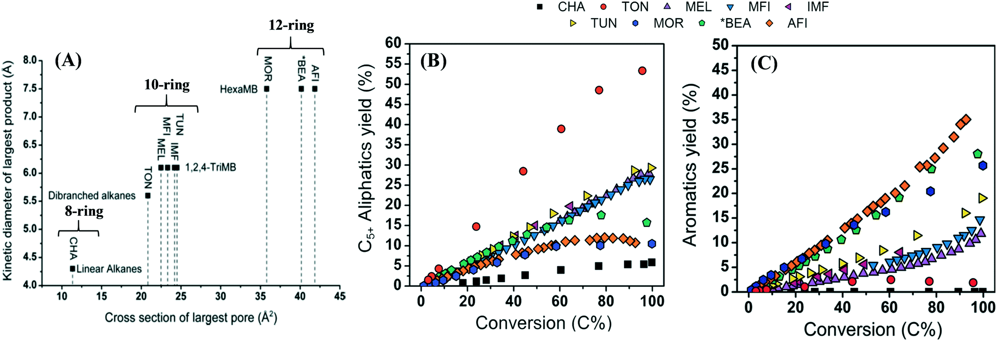 | ||
| Fig. 8 (A) Cross-section of the largest pore of zeolites versus kinetic diameter of the largest product. (B) C5+ aliphatic yield over various zeolites as a function of conversion, 423 K, P (methanol) = 0.01 MPa. (C) Aromatics yield over various zeolites as a function of conversion, 423 K, P (methanol) = 0.01 MPa,174 Bleken, S. Svelle, K. P. Lillerud and U. Olsbye, Catalysis, 2014, 26, 179–217, reproduced by permission of The Royal Society of Chemistry. | ||
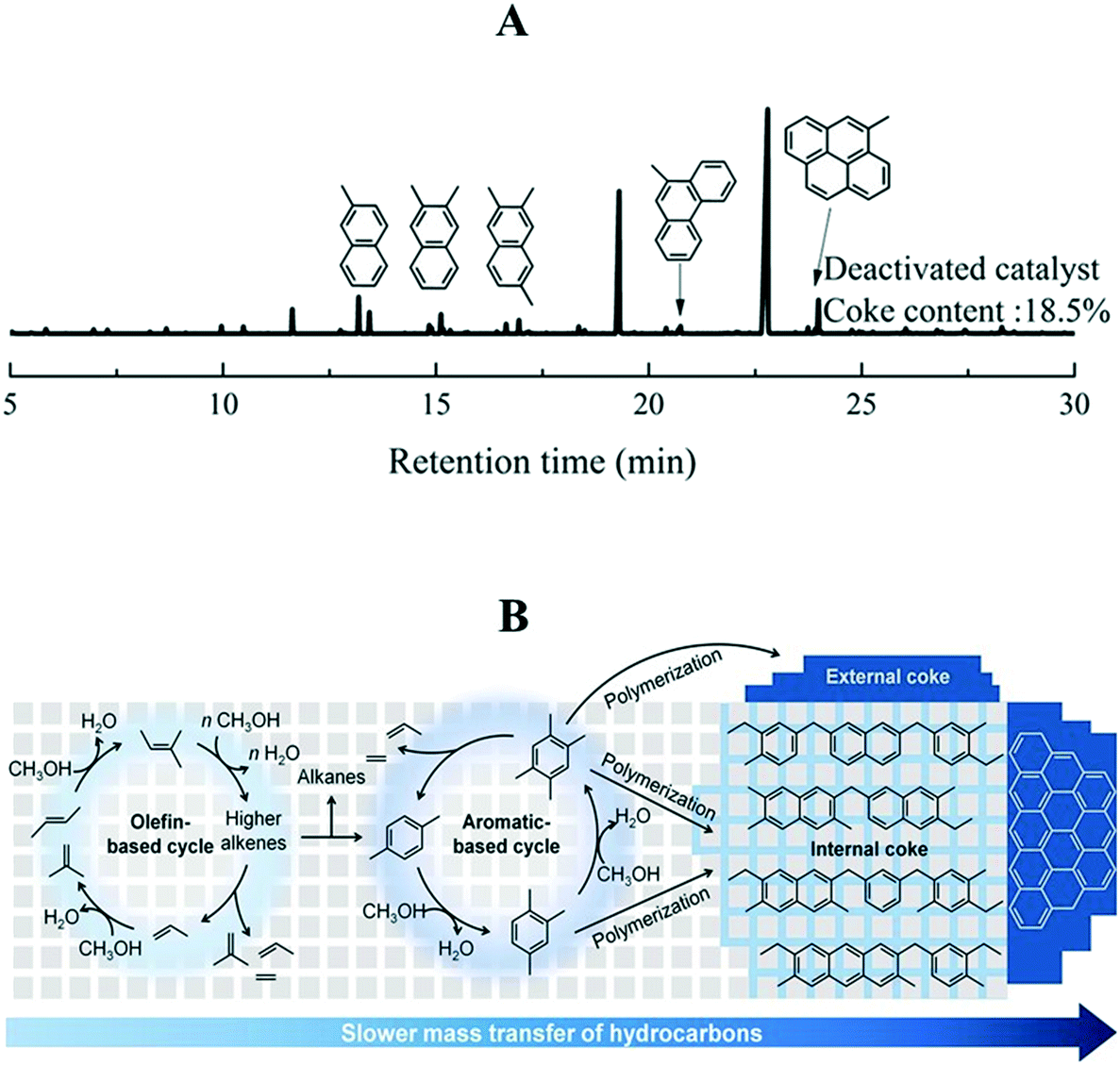 | ||
| Fig. 9 (A) GC-MS chromatogram of organic species occluded in the deactivated SAPO-34 catalyst, reprinted (adapted) with permission from X. Zhao, J. Li, P. Tian, L. Wang, X. Li, S. Lin, X. Guo and Z. Liu, ACS Catal., 2019, 9, 3017–3025, Copyright (2019) American Chemical Society. (B) Internal and external coke formation mechanism, 673 K, P (methanol) = 0.025 MPa, WHSV = 6.46 to 86.1 h−1, this article was published in Journal of Catalysis, S. Lee and M. Choi, Unveiling coke formation mechanism in MFI zeolites during methanol-to-hydrocarbons conversion, J. Catal., 2019, 375, 183–192, Copyright Elsevier (2019). | ||
Deactivation by coke demands frequent regeneration of the catalyst by burning off the coke. Therefore, it is highly recommended to increase the lifetime of catalysts either by modifying the reaction environments or via the catalyst design.
2.2.2.1 Effect of co-feeding H2, H2O, and CO2 on catalyst lifetime. Arora et al.192 investigated the effect of H2 co-feeding (0.4–3 MPa) on catalyst lifetime (SAPO-34) during the MTH reaction (673 K and 0.013 MPa of methanol). Almost 2.8 to 70 times greater catalyst lifetime was observed in the presence of H2. Similar catalyst stability was also observed when ZSM-5 and SSZ-13 catalysts were used (3 and 4.5 times increase in stability for ZSM-5 and SSZ-13, respectively). It was rationalized that H2 participated in the hydrogen transfer reactions to intercept the pathways promoting the formation of polycyclic compounds inside the zeolite cage. For instance, the intermediate 1,3-butadiene can undergo hydrogenation in the presence of H2, thus limiting its chances to form aromatic and polycyclic compounds susceptible to coke formation.185 Zeolites have been reported to perform the hydrogenation/dehydrogenation reactions to a limited extent.193,194 At a certain methanol partial pressure, the dehydrogenation of methanol to formaldehyde can occur. Formaldehyde can undergo Prins condensation with olefins and aromatics in the HCP to generate inactive polycyclic aromatic species. Co-feeding of H2 is presumed to reduce the formaldehyde induced polycyclic aromatics formation. Analysis of the occluded reaction species in the completely deactivated SAPO-34 showed that H2 co-feeding did not change the composition of chemical species (pyrene species), but only delayed the deactivation rate.192 This delayed deactivation behavior caused by H2 co-feeding was also observed by others when other zeolite catalysts such as SSZ-39, FER, and BEA were used for the reaction.185 The only detrimental effect of H2 co-feeding is the formation of saturated products when used at very high pressures.192
The effect of co-feeding of both H2 and H2O was reported by Zhao et al.195 The authors reported a synergetic effect of H2O and H2 in improving the lifetime of the SAPO-34 catalyst (Fig. 10A). Protonation of H+ sites by H2O generates H3O+ ions.196 These H3O+ ions have been reported to reduce the activation energy for hydrogenation reactions.197 As a result, the carbenium ions generated from the aromatics, confined in SAPO-34, can easily undergo hydrogenation, inhibiting the coke formation, at the same time, hydrogenating the heavy aromatic deposits to active aromatic intermediates (HCP mechanism), thereby increasing the catalyst lifetime. The main advantage of co-feeding H2O along with H2 is that the propylene selectivity could be improved.195 And the main disadvantage of H2O co-feeding is that, at a high amount of H2O, the zeolite can undergo dealumination leading to irreversible deactivation.198,199
 | ||
| Fig. 10 (A) Effects of different reaction environments (N2, H2, H2O, and H2–H2O mixture, 723 K, 4 MPa, methanol WHSV = 4.0 h−1, GHSV = 13069 h−1) on the lifetime of a SAPO-34 catalyst, reprinted (adapted) with permission from X. Zhao, J. Li, P. Tian, L. Wang, X. Li, S. Lin, X. Guo and Z. Liu, ACS Catal., 2019, 9, 3017–3025, Copyright (2019) American Chemical Society. (B) Effect of diffusion path length on catalyst lifetime, reprinted (adapted) with permission from Y. Shen, T. T. Le, D. Fu, J. E. Schmidt, M. Filez, B. M. Weckhuysen, and J. D. Rimer, ACS Catal., 2018, 8, 12, 11042–11053, Copyright (2018) American Chemical Society. | ||
Zachariou et al.200 also found the positive effect of H2O in improving the catalyst lifetime. The authors used methanol and dimethyl ether as reactants. Rapid deactivation was observed when dimethyl ether was used as a reactant. The deactivation was delayed when methanol was used instead of dimethyl ether. This was ascribed to the presence of H2O that aided the regeneration of acid sites required for the methylation of aromatic compounds (HCP mechanism). The composition of coke also changed in the presence of H2O. In its presence, the ratio of aromatic to aliphatic species in the coke was found to be lower.200
The effect of CO2 co-feeding (0.1 MPa) during the MTH reaction has also been reported. Magzoub et al.201 employed a 3D-printed monolith ZSM-5 catalyst doped with various elements like Ga, Cr, Cu, Zn, Mo, and Y. The CO2 co-feeding slightly improved the lifetime of the catalysts (673 K, WHSV = 0.35 h−1), probably via the reverse Boudouard reaction. A consequence of CO2 co-feeding is that it promoted cracking and dehydrocyclization, leading to the production of light alkanes (methane and ethane) and benzene–toluene–xylene compounds.201
Overall, the co-feeding of H2, CO2, and H2O was found to be conducive in delaying the deactivation rate thereby improving the catalyst lifetime. Hence during the CTH process, these gases (CO2 and H2) and H2O are anticipated to impart a positive effect on the catalyst lifetime.
2.2.2.2 Effect of catalyst structure and composition on deactivation. An alternative approach to improve the catalyst lifetime is to modify the catalyst structure, for instance, introduce mesoporosity. Kim et al.184 reported the use of hierarchical ZSM-5 with intracrystalline mesopores for the MTO reaction. In the synthesized catalyst, the Al atoms were predominantly positioned in the straight channels as compared to the conventional ZSM-5 catalyst, where the Al atoms are found in the intersections between sinusoidal and straight channels. The lifetime of the catalyst with hierarchical mesopores was almost 3 times longer than the microporous ZSM-5 catalyst (673 K, WHSV = 4.75). The presence of mesopores served as a carbon reservoir to accommodate the coke and thus minimize the blockage of micropores.184 The presence of mesopores enhanced the diffusion of coke precursors out of the micropores, allowing the zeolite to accommodate more coke with large structures, and thereby increasing its lifetime.
Another factor contributing to the deactivation of zeolite catalysts during industrial applications is the presence of binders (non-zeolitic materials used to improve the mechanical properties of the zeolite catalysts). Binders can block the pore accessibility, thereby accelerating the propensity of intermediate molecules to form coke precursors.202 To circumvent this issue, Bingre et al.203 introduced pore-forming agents (surfactants) to a boehmite binder before extruding it with ZSM-5. Calcination of the extrudate catalyst burned off the pore-forming agents leaving meso/macro pores within the extrudate. These meso/macropores solely existed in the binder leaving the zeolite structure intact. Meso/macro pores in the binder favored improved mass transfer of molecules and were able to trap and hold larger quantities of coke as compared to the conventional extrudate catalyst (723 K, WHSV = 2.0). The coke's ideal position in the meso/macro pores was beneficial to retain the exposure of active sites of the zeolite for a longer reaction time, thus indirectly improving the catalyst lifetime to almost double.203
In the case of the ZSM-5 catalyst, the coke deposition is usually observed at the outer rim of the zeolite crystal because aromatic products diffusing out the micropores are condensed at the external surfaces of the crystals. Over time, the pore entrance becomes blocked by the coke, causing the accumulation of hydrocarbons at the channel intersections completely limiting access to internal active sites. Acid sites on the external surface of the zeolites deactivate more quickly than those located inside the crystals due to a lack of shape selectivity. Therefore, to improve the catalyst lifetime, Goodarzi et al.191 attempted a surface passivation technique involving the introduction of an inert porous shell of silicalite-1 with a thickness of 15 nm on the surface of a mesoporous ZSM-5 catalyst, thus replicating a core–shell structure. In comparison to the mesoporous ZSM-5 without the protective shell, the one with the protective shell had 10 times longer catalyst lifetime extending up to 70 hours of reaction as compared to 7 hours, and 12 times higher conversion capacity based on the acid sites (from 27 to 63%).
To unravel the effect of catalyst composition on deactivation, Chowdhury et al.204 compared the performance of Ca-modified and unmodified ZSM-5 in the MTH reaction (773 K, WHSV = 8 h−1). The Ca-modification significantly improved the lifetime of the catalyst. This was attributed to the fact that the Lewis acid site may promote (imparted by Ca-incorporation) suppression of the aromatic cycle. The Ca-incorporation isolated the Brønsted acid sites, thereby inhibiting the carbene/ylide species.
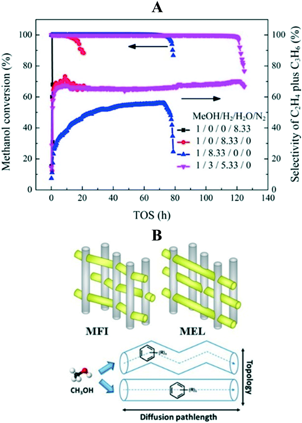
In order to investigate the effect of framework topology and diffusion path length on deactivation, Shen et al.205 used a series of ZSM-5 and ZSM-11 catalysts with different crystallite sizes for the reaction (623 K, WHSV = 9 h−1). As compared to ZSM-5 with a sinusoidal micropore structure, the ZSM-11 with straight micropore structure had almost a two-fold improved catalyst stability (from 4.5 to 8.5 hours) due to higher diffusivity (Fig. 10B). When the crystallite size of ZSM-11 was reduced from 750 nm to 150 nm, an 8-fold increase in catalyst lifetime was observed (from 1.7 to 13.5 hours), owing to the decrease in the diffusion path length. An increase in diffusion limitation favors the aromatic cycle to produce ethylene as the major product.205 A general conception regarding the effect of zeolite topology on catalyst lifetime is that the shorter the diffusion length or the smaller the crystallite size, the longer the catalyst lifetime.206–211
Zhang et al.213 applied room temperature methanol leaching as a regeneration technique for the deactivated ZSM-5 catalyst. After 2 hours of methanol leaching, the regenerated catalyst showed textural properties similar to the fresh ZSM-5 catalyst. However, the authors found that regeneration by calcination was more efficient in removing the coke than methanol leaching. One of the main disadvantages of methanol leaching in practical application is the requirement of cooling down the reactor for the leaching process.213
Li et al.212 introduced a rejuvenating process to the ZSM-5 catalyst bed during the MTH process to reactivate the catalyst. Toluene or H2O was fed to the reactor under the same experimental conditions for a certain period. After this, the methanol feeding was continued. The rejuvenation process decreased the pore volume and surface area (textural properties), and the acidity of the catalyst. Rejuvenation by toluene had generated new polyalkylbenzene species in the catalyst. These species could act as HCP intermediates to partially recover the activity of the catalyst. When H2O was used, the catalyst was found to be less effective, mainly due to the loss of acidity by dealumination.212 Altogether, the most efficient way to regenerate a deactivated catalyst is the calcination process and it is successfully practiced in industry via the use of fluidized bed reactors.169
3. Direct hydrogenation of CO2 to hydrocarbons
Hydrocarbons from CO2 have been synthesized using two processes; the first is a CO-mediated process and the second is a CH3OH-mediated process (Fig. 11). The focus here will be on the CH3OH-mediated process, as the CO-mediated process is out of scope of this review. Generally, CO-based hydrocarbon synthesis, called the Fischer–Tropsch process (FT), produces hydrocarbons with a statistical distribution, named Anderson–Schulz–Flory (ASF). The maximum selectivity for a desired hydrocarbon is limited by the ASF model. Apart from this route, the CH3OH-mediated hydrocarbon synthesis process has the advantage that the hydrocarbon yield does not follow the ASF model. In recent years, many studies report on the direct conversion of CO2 to hydrocarbons in a one stage reactor via a CH3OH-mediated process (Table 3). Direct CO2 hydrogenation is an efficient way to produce hydrocarbons using bifunctional catalysts. Bifunctional catalysts are a combination of CH3OH synthesis and CH3OH to hydrocarbon (MTH) catalysts. Up to now, various Cu, Pd, and oxide-based catalysts (In2O3 and ZnO) have been used for CH3OH synthesis from CO2, and different types of zeolites have been used for the synthesis of hydrocarbons from CH3OH.17,214,215 The direct route would be more economically and energy-efficient compared to the indirect two-stage route. In the case of the two-stage process, two reactors need to operate separately and in addition to the extra capital costs for another reactor stage there is a need to carry out separation processes between stages to separate the undesired intermediates from the process which requires additional energy. There are also efficiency advantages that a single stage process can offer since the equilibrium limitation of methanol synthesis is alleviated by the fact that methanol is directly converted to hydrocarbon products. CO is a major byproduct from CO2 hydrogenation, but in a one stage CO2 hydrogenation process, the selectivity for CO can be reduced since the methanol removal will be positive for the equilibrium limitation for the methanol synthesis from CO2, as will be explained below in greater detail. Inui et al. investigated the synthesis of gasoline with lower olefins from CO2 + H2via the CH3OH route in a two stage reactor.216,217 In the first reactor, CO2-rich syngas was converted to CH3OH on Cu–Zn–Cr–Al-oxides; further the total reaction mixture was directly fed to a second reactor connected in series, packed with a protonated Fe-silicate crystalline catalyst. Gasoline with 50% selectivity was formed in the second reactor from the CH3OH synthesized in the first reactor. As a side product, lower olefins were produced with gasoline, which could be an intermediate compound during gasoline synthesis.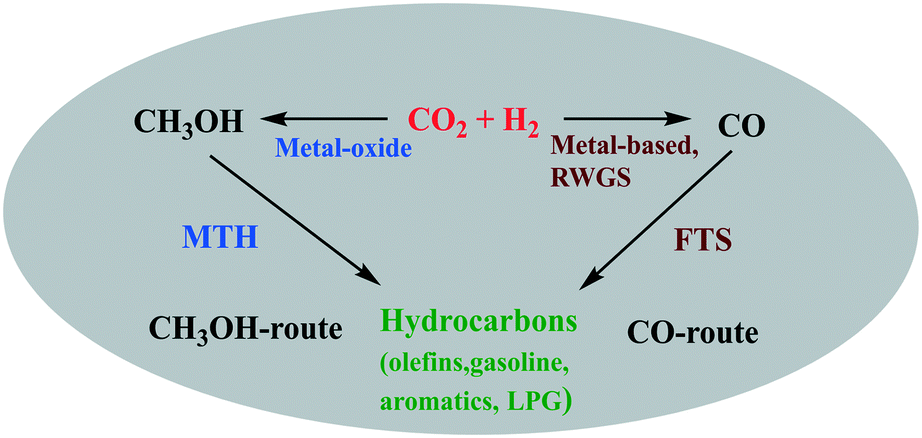 | ||
| Fig. 11 Pictorial representation of CH3OH-mediated or CO-mediated routes for direct hydrocarbon synthesis. | ||
| Catalysts | H2:CO2 |
T (K) | P (MPa) | CO2 conv. (%) | GHSV (h−1) | Major productsa | Selectivity for major products among hydrocarbonsb (%) | CO selectivityc (%) | S MeOH/DME (%) | Ref. |
|---|---|---|---|---|---|---|---|---|---|---|
| a Major hydrocarbon product among hydrocarbons. b Major hydrocarbon product selectivity among hydrocarbons. c CO selectivity based on CO2 feed. d Selectivity for methanol and DME based on CO2 feed, n.r. = not reported. | ||||||||||
| Zr–In2O3/SAPO-34 | 3 | 673 | 3 | 35.5 | 9000 | C2=–C4= | 76.4 | 85.0 | 0/n.r. | 222 |
| Zn–ZrO2/SAPO-34 | 3 | 653 | 2 | 12.6 | 3600 | C2–C4= | 80.0 | 47.0 | n.r./n.r. | 227 |
| In2O3–ZrO2/SAPO-34 | 3 | 673 | 1.5 | 19.0 | 3000 | C2= + C3= | 80–90 | >80 | n.r/n.r. | 225 |
| In2O3/H-ZSM-5 | 3 | 613 | 3 | 13.1 | 9000 | C5+ | 78.6 | <45 | 0/n.r. | 221 |
| ZnGa2O4/SAPO-34 | 3 | 643 | 3 | 13.0 | 5400 | C2=–C4= | 86.0 | 46.0 | 0/0 | 229 |
| In2O3–ZrO2/SAPO-34 | 3 | 653 | 3 | 26.2 | 9000 | C2=–C4= | 74.5 | 63.9 | 0.2/n.r. | 223 |
| In2O3–ZrO2/SAPO-5 | 3 | 573 | 3 | 6.7 | 4000 | C2–C4 | 83.0 | 43.0 | <0.5/n.r. | 226 |
| ZnAlOx/H-ZSM-5 | 3 | 593 | 3 | 9.1 | 2000 | Aromatics | 73.9 | 57.4 | <0.5/<0.2 | 232 |
| In2O3–ZnZrOx/SAP-34 | 3 | 653 | 3 | 17.0 | 9000 | C2–C4= | 85.0 | 54.0 | 0/n.r. | 224 |
| Cu–CeO2–SAPO-34 | 3 | 669 | 2 | 13.2 | 5800 | C2=–C4= | 61.8 | 56.8 | n.r./n.r. | 231 |
| ZnZrO/HZSM-5 | 3 | 593 | 4 | 14.1 | 1200 | Aromatics | 73.0 | 44.0 | n.r./n.r. | 233 |
| Cr2O3/HZSM-5 | 3 | 623 | 3 | 33.6 | 1200 | Aromatics | 70.5 | 41.2 | 0/0 | 234 |
| CuZnZr@Zn–SAPO-34 | 3 | 673 | 2 | 19.6 | 3000 | C2=–C4= | 60.5 | 58.6 | n.r./n.r. | 228 |
There are various reports on the synthesis of lower olefins (butylenes, propylene, and ethylene) which are used industrially as chemical intermediates and also produced from the dehydration of lower alkanes218 and cracking of hydrocarbon feedstocks.219 At the lab scale, lower olefins have been synthesized using two stage processes and as a carbon source, syngas is used for CH3OH synthesis and further converted to lower olefins. Meanwhile in the case of CO2 to CH3OH, the formation of water is unavoidable which can lead to deactivation of both catalysts (for CO2 to CH3OH catalysts as well as CH3OH to olefin catalysts like zeolite). In addition, water can cause zeolite dealumination if present in too large quantities; however, as mentioned in section 2.2.2.1 of this review, it also prolongs the lifetime of the MTO catalysts by preventing coke deposition. Thus, it is a challenging task to synthesize hydrocarbons from CO2 in one stage.
Recently, In2O3-based catalysts have shown their excellent activity for CH3OH synthesis in the temperature range of 473–573 K (ref. 44, 142 and 143) (Table 2). While in this temperature range, zeolites are not active for C–C coupling. Generally, it is found that high temperature is more kinetically favorable for C–C coupling from methanol. For the synthesis of lower olefins from methanol, the temperature range of 673–723 K was found optimal over SAPO-34 which is a more favorable temperature range for the RWGS reaction too, but not for methanol yield (Tables 1 and 2).171,220 Thus, the big challenge is how to combine the two processes, which have different optimum operating conditions while mitigating the undesired side reactions. Many efforts have been made to synthesize such combined catalysts to achieve stable and excellent catalytic performance. Note that in all cases in the following paragraphs the reported selectivities for certain hydrocarbon products (or major hydrocarbon products) are based only among all hydrocarbon products whereas the reported CO/CH3OH/DME selectivities are based on total carbon from the CO2 feed.
Gao et al. prepared a bifunctional catalyst by mixing In2O3 and zeolite (ZSM-5) that showed 78.6% selectivity towards C5+ (based on hydrocarbons) with only 1% selectivity for CH4 at a CO2 conversion of 13.1%.221 In addition, less than 45% CO selectivity was observed. Moreover, when using beta zeolite, liquefied petroleum gas products (C3 and C4 paraffins) were formed and an enhanced CO2 conversion was observed at higher pressure and H2/CO2 ratio while the CO selectivity was decreased. Later, the same group reported 76.4% selectivity for lower olefins (C2=–C4=) with ∼35% CO2 conversion over a composite catalyst of In–Zr oxide and SAPO-34 zeolite.222 However, the CO selectivity over this composite was above 80% under different reaction conditions. The CO2 activation occurred on the In–Zr oxide, whereas the zeolite was responsible for C–C coupling. The authors studied the effect of reaction pressure and the feed ratio of H2/CO2 and found that CO2 conversion increased with the H2/CO2 ratio while the selectivity for C2=–C4= decreased with increasing pressure and H2/CO2 ratio. It was also observed that when the space velocity was increased from 4500 to 15750 mL gcat−1 h−1, the selectivity for lower olefins increased from 68% to 84% and the selectivities for C5+ and CH4 were decreased.
To understand the role of ZrO2, a series of bifunctional catalysts composed of In–Zr composite oxides having different atomic ratios of In and Zr, and SAPO-34 zeolite were prepared by Dang et al. and screened for direct CO2 hydrogenation into lower olefins.223 The catalysts gave 15–27% conversion of CO2 with 96% selectivity for C2–C4 among the hydrocarbon products (65–80% for C2=–C4= and 13–30% for C20–C40), and the selectivity for CH4 was merely 2.5%. The selectivity for CO via the RWGS reaction was less than 70%. The authors demonstrated by combined experimental and computational studies that In1−xZrxOy mixed oxide was formed after the incorporation of Zr into In2O3. This mixed oxide was found to contain more oxygen vacancies with higher binding energies for the reaction intermediates compared to pure In2O3. Further, the CO2 adsorption behavior was studied on the mixed oxide using DFT calculations and it was found that the CO2 and reaction intermediates were adsorbed more strongly on the oxygen vacancy sites which were situated near the Zr dopant than that on pure In2O3. Thus, the presence of a certain amount of Zr in In2O3 (In:Zr = 4:1) increased the selectivity for CH3OH from CO2 and decreased the RWGS activity. Consequently, the formation of hydrocarbons also increased with the incorporation of Zr. However, it was also observed that an excess amount of Zr in In2O3 significantly decreased the olefin selectivity due to the smaller pore size of the oxides and longer average distance between the metal-oxide and zeolite.
Recently, a composite of In2O3–ZnZrOx oxides and SAPO-34 was prepared in which In2O3 (8 nm) was supported on ZnZrOx and mechanically mixed with a series of SAPO-34 zeolites having different crystal sizes and pore structures.224 The composite catalyst was used for direct CO2 hydrogenation to lower olefins and a 85% selectivity for C2=–C4= was found among all the hydrocarbons with a CO2 conversion of 17% and CO selectivity of 54%. It was found that the selectivity for C2=–C4= increased with decreasing pore size. The reason for this was that the diffusion length can be shortened from the surface to the acid sites inside the pores of the zeolite and this helps to provide an efficient mass transfer of intermediate species for C–C coupling to produce lower olefins, whereas the pore structure and the crystal size of the zeolite did not influence the equilibrium of the RWGS reaction. A similar type of composite was synthesized by Gao et al., fabricated from In2O3/ZrO2 and SAPO-34 for direct conversion of CO2 to light olefins (ethylene and propene).225 The authors reported the selectivity for light olefins in the range of 80–90% with ∼20% CO2 conversion. The influence of composition on the selectivity for hydrocarbons and conversion of CO2 was studied and it was found that equal mass of In2O3/ZrO2 to SAPO-34 gives a relatively high yield of light olefins, whereas higher content of In2O3/ZrO2 in the composite increased the CO2 conversion and selectivity for CO (>80%) which is a side product during CH3OH synthesis over In2O3/ZrO2. Recently, Wang et al. reported results for the same type of catalyst in which SAPO-34 was replaced with SAPO-5.226 This bifunctional catalyst integrated In2O3/ZrO2 and SAPO-5 and exhibited an excellent selectivity towards C2–C4 (83%) lower hydrocarbons with a lower yield of CH4 at 6.7% conversion of CO2. A comparison study for hydrocarbon selectivity over SAPO-34 and SAPO-5 was carried out and it was found that the total selectivity for C2–C4 (83% in hydrocarbons) over SAPO-5 was higher than that over SAPO-34. The selectivity for CO was found to be between 40 and 60% over this composite and it decreased by increasing the space velocity and granule mixing of In2O3/ZrO2 and SAPO-5 while it increased with temperature.
Li et al. fabricated a tandem catalyst that was a composite of ZnO–ZrO2 and a Zn-modified SAPO-34 and over this catalyst, they found 12.6% CO2 conversion with 80% selectivity for lower olefins (C2=−C4=) which was the highest among all the hydrocarbon products (3% CH4, 14% C2–C40, and 3% C5+).227 It was concluded that the ZnZrO produced CH3OH from CO2 hydrogenation and the lower olefins occurred on the SAPO catalyst from CH3OH with 47% CO selectivity. This catalyst was found to be promising for industrial applications, since it has good sulfur and thermal resistance under the mentioned reaction conditions (Table 3). The highly efficient conversion of CO2 to lower olefins on tandem catalysts can be attributed to the thermodynamic and kinetic coupling.
To obtain high selectivity towards light olefins from CO2 hydrogenation, a core–shell structural (CuZnZr)CZZ@SAPO-34 composite catalyst was prepared and compared with CZZ/SAPO-34 which was prepared by physical mixing.228 CZZ/SAPO-34 (mass ratio of 4:1) gave 9.7% CO2 conversion with 34.7% olefins selectivity and 58.5% CO selectivity. It was found that the physically mixed CZZ/SAPO-34 with a mass ratio of 4:1 reduced the acidity of the catalyst which is a factor that could increase the selectivity for lower olefins, but surprisingly the catalyst gave lower selectivity to olefins and higher selectivity for CH4 compared to CZZ/SAPO-34 with a mass ratio of 2:1. This could be due to the strong hydrogenation ability of CZZ at the reported temperature. Meanwhile in the case of the core–shell composite (CZZ@SAPO-34), the higher mass ratio (CZZ@SAPO-34 (4:1)) gave higher selectivity for olefins with lower selectivity for CH4 compared to the lower mass ratio of CZZ@SAPO-34 (2:1). This is possibly due to the reduced interface between CZZ and SAPO-34, because of the great difference in the particle size of CZZ in CZZ@SAPO-34 and CZZ/SAPO-34 catalysts. In addition, it was stated that the hydrogenation activity was weakened in the case of CZZ@SAPO-34, which was found beneficial for lower olefins as the selectivity for lower olefins was increased via restraining the secondary hydrogenation reaction. It was also found that the acid density of SAPO-34 affected significantly the selectivity for the product. The authors reduced the acid density and total acidity of SAPO-34 by Zn-modification which then greatly increased the CO2 conversion and selectivity for lower olefins on the CZZ@Zn–SAPO-34 (4:1) catalyst (see Table 3). No change was observed in CO selectivity due to the interface or the acidity of CZZ@Zn–SAPO-34 (4:1), CZZ@SAPO-34 (2:1), and CZZ/SAPO-34 (4:1).
Another new oxide-based catalyst was reported recently by Liu et al.229 This bifunctional catalyst was composed of a spinel structure of ZnGa2O4 and SAPO-34 which gave 86% C2–C4 olefins and 46% CO selectivity with a CO2 conversion of 13%. It was reported that the molar ratio of Zn/Ga in ZnGa2O4 plays an important role in adsorption, activation and conversion of CO2 as it influenced the density of oxygen vacancies in the catalyst.230
Sedighi et al. reported a new composite for direct hydrogenation of CO2 to lower olefins (C2=–C4=) via CH3OH as an intermediate.231 A crystalline hybrid catalyst (CuCe/SAPO-34) was prepared by a physical coating process in which the outside surface of the SAPO-34 powder was covered with Cu/CeO2. The CO and olefin selectivity were found to be 57.8 and 61.8% (based on hydrocarbons), respectively, with 13.2% CO2 conversion at 669 K. The CO2 conversion and CO selectivity were promoted by high temperature.
Several aromatic hydrocarbons have been successfully synthesized by CO2 hydrogenation. A composite catalyst of ZnAlOx and H-ZSM-5 was synthesized and tested for CO2 hydrogenation.232 The catalyst yielded 57.4% selectivity for CO, 73.9% selectivity for aromatics (among the HCs) with 9.1% CO2 conversion, and 0.4% CH4 selectivity. It was found that Zn2+ activated the CO2 hydrogenation in ZnAlOx whereas Si–H-ZSM-5, containing the composite zeolite, was selective for p-xylene (58.1%), ethylene and propylene. During the reaction, DME, CH3OH, and olefins were found as reaction intermediates. The RWGS reaction was suppressed by increasing the ratio of H2/CO2 and introducing CO without affecting the aromatization.
A tandem catalyst ZnZrO/ZSM-5 was prepared and screened for the hydrogenation of CO2 to aromatics.233 The catalyst exhibited 14% conversion of CO2 with an aromatics selectivity of up to 73% (based on HCs) and 44% CO selectivity. Thermodynamic coupling was observed on the tandem catalyst where CHxO intermediates were formed on the surface of ZnZrO from CO2 hydrogenation and then the intermediates transferred to the pores of H-ZSM-5 and produced aromatics. It was found that the presence of H2O in H-ZSM-5, produced from CO2 hydrogenation over ZnZrO, helped stabilize the ZnZrO/ZSM-5 catalyst by suppressing the production of polycyclic aromatics.
Wang et al. presented a novel tandem catalytic process for CO2 hydrogenation to aromatics in a single-step (Fig. 12).234 A CH3OH-mediated pathway was found to occur over Cr2O3/H-ZSM-5 catalysts, which were prepared by physical mixing of Cr2O3 and H-ZSM-5. The catalyst yielded 70.5% selectivity for aromatics among all the hydrocarbons and 41% CO selectivity with 33.6% conversion of CO2. Meanwhile, the selectivity for CH4 and CO was successfully suppressed to 1.5% and 11.4%, respectively, by co-feeding 5.4 vol% CO in the feed gases whereas the aromatics selectivity and the CO2 conversion increased up to 75.9 and 34.5%, respectively. In addition, to enhance the selectivity towards benzene, xylene, and toluene, a structural change was carried out to form a core–shell type catalyst. The core–shell structured zeolite catalyst enhanced the selectivity for benzene, toluene and xylene from 13.2% to 43.6% (in aromatics) while the CO2 conversion was decreased from 34.5 to 27.6%. In addition, by tuning the mass ratio of both components of the tandem catalyst and the acid strength of zeolites, the catalytic performance could be influenced. The developed catalyst exhibited excellent stability for a 100 h reaction run. Most studies discussed the effect of space velocity on selectivity. An enhancement in selectivity to hydrocarbons was observed by increasing the space velocity, whereas the selectivity for CO was suppressed after the combination of zeolite with a metal oxide catalyst. The method used to combine catalysts also affects the catalyst activity and selectivity for products which is termed as proximity and will be discussed in section 3.3. In other words, reducing the contact time between the catalyst bed, feed gas and CH3OH is favorable for timely diffusion into the zeolite pores for conversion to hydrocarbons.
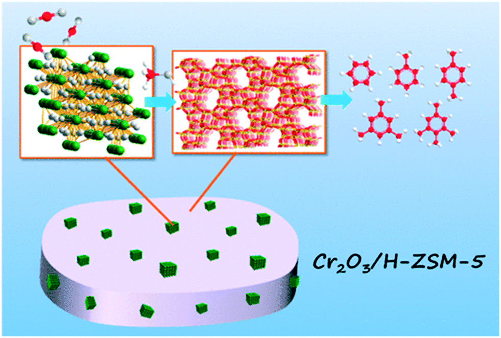 | ||
| Fig. 12 A pictorial representation on the direct conversion of CO2 to aromatics over Cr2O3/H-ZSM-5. “Reprinted (adapted) with permission from Y. Wang, L. Tan, M. Tan, P. Zhang, Y. Fang, Y. Yoneyama, G. Yang and N. Tsubaki, ACS Catal., 2018, 9, 895–901. Copyright (2019) American Chemical Society”. | ||
In most of the studies listed in Table 3, lower olefins are the major products among the hydrocarbons. The synthesis of lower olefins was explained based on the synergic interaction between two catalysts which were responsible for methanol synthesis and the MTO reaction. However, it is challenging to selectively synthesize lower olefins from CO2 using the reaction coupling strategy, since the MTO reaction is more favorable at higher temperatures (>623 K)235 whereas the CO2 to methanol reaction is thermodynamically unfavorable at higher temperature. It was found that after mixing the two catalysts (methanol synthesis catalyst and MTH catalyst), the bifunctional catalyst shows a unique property which shifts the CH3OH synthesis equilibrium and decreases the selectivity for CO and CH4. The immediate conversion of methanol into lower olefins might be a driving force for the higher reactivity to methanol and lower selectivity towards CO. Methanol has been reported as an intermediate in most of the studies (Table 3) while DME was also found with methanol in a few studies. It was observed that methanol and CO were the main products with the metal-oxide catalyst alone, but when the metal oxide was mixed with zeolite, then the selectivity for methanol was found to be near zero or less than detectable under the reaction conditions listed in Table 3, whereas the CO selectivity was also reduced. It means that all produced methanol/DME could be converted into hydrocarbons. In some cases, small amounts of methanol were found unreacted when reaction conditions such as the mass ratio of metal oxide and zeolite catalysts, space velocity, pressure, and temperature were changed. For example, aromatics synthesis was examined on a ZnAlOx/H-ZSM catalyst, and CH3OH and DME were observed as intermediates.232 A higher selectivity for methanol (above 98%, excluding CO) was obtained with ZnO alone, whereas the selectivity for CH3OH was reduced (to below 60%) after the addition of AlOx and DME was found with CH3OH with almost equal selectivity. Further, with the addition of H-ZSM, the selectivity for both CH3OH and DME dropped. The preparation method and the packing method of ZnAlOx and H-ZSM also changed the selectivity for CH3OH and DME. For example, the selectivity for CH3OH + DME was higher than 0.5% when they were prepared by grinding mixing, whereas the selectivity dropped to below 0.5% when both catalysts were mixed by granule mixing. Only DME was observed when both catalysts were packed in a dual-bed configuration in the reactor with ZnAlOx upstream from H-ZSM.
The selectivities for CH3OH and DME were also increased with higher space velocity in the case of the ZnAlOx/H-ZSM catalyst. It was stated that the rate of formation of CH3OH from CO2 hydrogenation is higher than the hydrogenation of CO. Thus, there is less chance to obtain CH3OH from CO over metal oxides.229 The reason for the lower CO selectivity with combined metal oxide and zeolite catalysts might be because both methanol and CO formation compete for consumption of the same reactants (CO2 and H2). At the high temperature used for direct CO2 hydrogenation to hydrocarbons, methanol synthesis should be strongly equilibrium limited and this reaction is favored by high reactant and low product (methanol and water) concentrations. The progress of the competing CO formation reaction lowers the reactant concentration and increases water, which favors reverse methanol synthesis. However, if methanol is immediately consumed by its conversion into hydrocarbons, then methanol synthesis can proceed with less restrictive equilibrium limitations and the negative effects that CO formation would have on its equilibrium. In addition, unhindered methanol formation consumes more reactants which reduces the driving force for the CO formation reaction. However, detailed studies of this are still lacking in the literature.
3.1 Catalyst preparation methods
We have seen in the sections above and as evident in Table 3 that direct CO2 hydrogenation to hydrocarbons always involves bifunctional catalyst systems, so in this section, the methods of preparation of these catalysts are discussed, with the intent to achieve varying degrees of contact between the two catalysts. Also, below in section 3.3, the importance of the proximity of the catalysts will be discussed. Most of the bifunctional catalysts are prepared by the solid mixing of methanol synthesis and hydrocarbon synthesis catalysts. Generally, this process is called granulation, which can be categorized into two parts, dry granulation and wet granulation. In the case of dry granulation, a mechanical compression can be used to mix the solid particles, while granulation with a liquid plays a role in facilitating the agglomeration.236 As most of the studies in the case of bifunctional catalysts use a dry granulation process to prepare catalysts, only this method will be explained in detail here to keep this section brief.A bifunctional catalyst was prepared using dry granule mixing, in which In2O3 and HZSM-5 were pressed and crushed to obtain 250 to 400 μm granule sizes and then both granule samples were mixed in an agate mortar. Further, the mixed sample was again pressed, crushed and sieved to obtain the above-mentioned particle size.221 A similar method was used to prepare In2O3/SAPO-34 and In–Zr/SAPO-34 by the same group.222 Another group prepared a mixed hybrid catalyst of In2O3/ZrO2 and SAPO-34 by mixing these samples in a certain ratio. Then this mixed powder was compressed, crushed, and sieved to 10–20 mesh particles.225 The In2O3/ZrO2 sample was prepared by a deposition–precipitation method. Bifunctional catalysts were reported to be prepared by shaking In2O3–ZnZrOx and SAPO-34 granules in a vessel.224 In2O3/ZnZrOx was synthesized using an impregnation method and ZnZrOx was prepared by a co-precipitation method. A tandem catalyst, namely ZnZrO/SAPO-34, was synthesized using physical mixing in which smaller size solid solutions of ZnZrO were scattered on the outer surface of the zeolite and both components retained their individual structure.227 Recently, a crystalline CuCe/SAPO-34 composite was prepared using a physical coating method.231 In this process, the outside surface of SAPO-34 was covered with Cu/CeO2, with the help of an alkaline-silica sol binder. Further, the sample was calcined at 823 K for 4 h. A core–shell structure of the (CuZnZr)CZZ@SAPO-34 composite catalyst was prepared with a physical coating method.228 In this method, the outer surface of CuO–ZnO–ZrO2 was covered with zeolite SAPO-34 with the help of an alkaline silica binder. Further, the catalyst was calcined at 773 K for 2 h.
3.2 Reaction mechanism and intermediates for direct CO2 hydrogenation to hydrocarbons
One key challenge for the selective synthesis of hydrocarbons from CO2 is the selection of a suitable CO2-to-CH3OH active catalyst that appropriately matches with the MTH reaction catalyst. As described above, bifunctional catalysts are effective for the synthesis of hydrocarbons. They are composed of a metal-oxide like In2O3–ZrO2, ZnO–ZrO2, Cr2O3, ZnCrOx, ZnGa2O4 and ZnAlOx which could activate CO2 and catalyze CO2 to CH3OH and/or DME in the temperature range of 573–673 K and zeolites such as HZSM, SAPO, and beta have been used to control the hydrocarbon selectivity due to their strong acidity and unique pore structure.225,237,238 It could be possible that the active sites and the intermediates should be mostly the same in the bifunctional catalysts as for the individual catalysts when they are used separately to perform CH3OH and hydrocarbon synthesis. However, the product selectivity and catalyst activity were found to be different when both catalyst components were combined and used as a bifunctional catalyst. Some groups have studied the reaction mechanism by DRIFT and DFT calculations.141,230DFT calculations were carried out to study the catalytic cycle of CO2 to CH3OH over In2O3 oxygen vacancies as discussed earlier in this review.221 Further the formed CH3OH transfers to the zeolite where C–C coupling occurs at the acidic site of the zeolite and produces various hydrocarbons via the hydrocarbon-pool mechanism which is discussed earlier in section 2.2.1.2. The surface oxygen vacancies are increased by doping Zr into In2O3.222 Similar observations were reported by Dang et al. after Zr doping into In2O3.223 Later, the same group performed various experiments with an empty reactor, bare In2O3–ZnZrO and SAPO-34 to explain the reaction mechanism of CO2 hydrogenation over In2O3–ZnZrOx/SAPO-34 catalysts under the same reaction conditions.224 Over the In2O3–ZnZrO catalyst, CH3OH and CO were the major products. But after combination with the zeolite, the selectivity for CO decreased, and the selectivity for hydrocarbons increased. It was observed that the CHxO species generated over In2O3–ZnZrOx further transferred to the zeolite for C–C coupling on the Brønsted acid sites to produce hydrocarbons.
Li et al. proposed a reaction mechanism based on in situ DRIFT spectroscopy coupled with a mass spectrometer and found mainly HCOO* and CH3O* intermediates on the surface of ZnZrO but the IR studies showed a weak interaction of CH3O* on ZnZrO that favored the transfer of these species onto SAPO-34 for the formation of olefins.227 It was concluded that the CH3O*, HCOO* species, and gas-phase CH3OH were produced first via CO2 hydrogenation on ZnZrO and then the formed CH3OH transferred to acidic sites of SAPO-34 for lower olefins production. The authors found that the CO selectivity was significantly suppressed and the CH3OH selectivity was much higher in the case of a tandem catalyst compared with that for ZnZrO alone. These results indicated an effective coupling of these reactions (thermodynamic and kinetic coupling), where reactions over the tandem catalyst were more effective than the sum of reactions over individual catalysts (CO2 to CH3OH and MTH). Later, a similar mechanism was observed by the same group over a ZnZrO/HZSM-5 catalyst.233 In this case, HCOO*, CHO*, and CH3O* species were detected over the tandem catalysts during CO2 hydrogenation where CH3O* species most probably diffuse to zeolite HZSM-5 to make first light olefins and then aromatics from the lower olefins.
Liu et al. conducted in situ infrared (IR) spectroscopic measurements to propose a possible reaction mechanism for CO2 hydrogenation on a ZnGa2O4 catalyst.229 The authors demonstrated that the oxygen vacancy sites on ZnGa2O4 account for CO2 activation to a CH3OH intermediate and interaction with SAPO-34 can suppress the undesirable CO formation via the RWGS reaction, and was also responsible for the synthesis of hydrocarbons from CH3OH. Carbonate species were observed on the pre-reduced ZnGa2O4 after the adsorption of CO2 and after the introduction of H2, HCOO* and CH3O* were generated on the surface of ZnGa2O4 (Fig. 13). It was found that the –Zn–O– and –Ga–O– pairs were responsible for generating H species (H*) by activating H2 and then these H species bind with activated CO2 to form CH3O* species. The CH3O* species further formed CH3OH that can be transferred into the pores of SAPO-34 and could produce lower olefins. The effect of oxygen-vacancies and water on CO2 adsorption on the (111), (110), and (100) surfaces of ZnGa2O4 was studied using DFT slab calculations.230 In some reports, the mesoporous ZnGa2O4 was found to be an effective photocatalyst for the photoreduction of CO2 to CH4.239
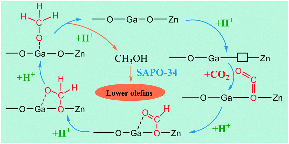 | ||
| Fig. 13 Possible mechanism of CO2 conversion into hydrocarbons via CH3OH intermediates over Zn–Ga–O catalysts. Reproduced from ref. 218 with permission from the Royal Society of Chemistry. | ||
Ni et al. proposed a mechanism for CO2 hydrogenation to aromatics over ZnAlOx/H-ZSM-5 based on the catalytic results and DRIFTS studies.232 According to this mechanism, surface formate species were formed on ZnAlOx and further hydrogenated to form CH3O* species. Then, the methoxy species dissociated to intermediates including CH3OH and DME which when transferred to H-ZSM-5 were further transformed to olefin intermediates. Finally, the formed olefins were converted to aromatics inside the micropores of H-ZSM-5. In addition, CO2 hydrogenation over ZnAlOx generates more surface formate species compared to CO hydrogenation.
The mechanism of aromatics synthesis directly from CO2 over Cr2O3/HZSM-5 was studied by in situ DRIFTS to gain more insights into the reaction pathway.234 On Cr2O3, symmetric and asymmetric vibrations were observed related to HCOO* species which have been recognized as an intermediate for CH3OH synthesis. Meanwhile in the case of Cr2O3/HZSM-5, the vibrations linked to HCOO* almost disappeared, but the CH3O* vibrations on the other hand appeared, indicating the formation of C–C coupling after the addition of HZSM-5. In addition, the vibrations related to the benzene ring and the substituted benzene ring were also observed in the spectra. Thus, the DRIFTS findings confirmed that a CH3OH-mediated pathway applies over the Cr2O3/HZSM-5 catalyst for CO2 hydrogenation to aromatics. It was found that the selectivity for aromatics over H-ZSM-5 was lower than that for Cr2O3/HZSM-5 composites which was used for direct synthesis of aromatics from CO2.
3.3 Proximity effect
The proximity and integration of the two-components play a crucial role in the catalytic performance of bifunctional catalysts for CO2 hydrogenation. The effect of proximity and integration on product distribution has been studied in previous reports.221,222,226,227,229,237,240Fig. 14 and 15 show that there are three main methods to study the effect of proximity which include the following: (1) dual-bed mode in which the metal oxide and zeolite are positioned in series inside the reactor without mixing and separated by quartz sand; (2) granule mixing that could be obtained by the mixing of micrometer size granules of both components of a bifunctional catalyst. In some reports, quartz sand is also mixed as a third component to moderate the proximity, and (3) powder mixing (mortar mixing) in which both components are ground to nanometer size and mixed properly to increase their proximity. We have discussed more about granule and mortar mixing in section 3.1.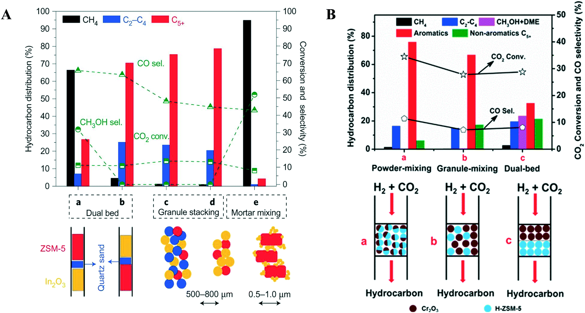 | ||
| Fig. 14 Influence of the integration manner of the active components in various studies (A) over the In2O3/HZSM-5 composite. Reprinted with permission from ref. 221. (B) over Cr2O3/H-ZSM-5. “Reprinted (adapted) with permission from Y. Wang, L. Tan, M. Tan, P. Zhang, Y. Fang, Y. Yoneyama, G. Yang and N. Tsubaki, ACS Catal., 2018, 9, 895–901. Copyright (2019) American Chemical Society”. (B) Over ZnZrO/SAPO. “Reprinted (adapted) with permission from Z. Li, J. Wang, Y. Qu, H. Liu, C. Tang, S. Miao, Z. Feng, H. An and C. Li, ACS Catal., 2017, 7, 8544–8548. Copyright (2017) American Chemical Society”. | ||
Gao et al. reported maximum conversion and selectivity for CO2 and C2–C4 respectively over In2O3/ZSM-5 in the case of granule mixing whereas minimum in the case of mortar mixing, indicating that the proximity decreases the active sites for methanol synthesis as well as hydrocarbon synthesis (Fig. 14A).221 In another experiment, the catalyst was packed in a dual-bed configuration in which two configurations were compared, one in which HZSM-5 was packed above the oxide and second below In2O3. In the first case, the authors found good selectivity for CH4 (66.3%) and CH3OH (31.8%) whereas the C5+ hydrocarbons selectivity was only 26.7%. However, in the latter case, the selectivity for CH4 decreased to 4.5% while the selectivity for C5+ increased to 70.4%. The CO selectivity was found to have a maximum of 65% in the case of dual-bed packing.
Furthermore, in the case of granule stacking, the C5+ selectivity enhanced and the selectivity for CO (<45%) and CH4 decreased significantly, whereas the CO2 conversion only changed slightly. The catalyst performance was the same with and without addition of quartz sand in the case of granule stacking. Further, the distance between In2O3 and ZSM-5 was decreased by grinding them in an agate mortar into powder form to explore the effect of their intimate contact. In the case of mortar mixing, the much smaller In2O3 particles having a particle size of 10 nm were in a much closer contact with the 500–800 nm HZSM-5 particles. The authors found very low selectivity (4.2%) for C5+ hydrocarbons and high selectivity for CH4 (94.3%) among the hydrocarbons excluding alcohols and CH3OH (51.9%) with 8% CO2 conversion. The results suggested that close contact decreased the synergistic effect between In2O3 and ZSM-5 and caused a significant deactivation of HZSM-5. Similar observations were found over In–Zr/SAPO-34 and Na–Fe3O4/HZSM-5 catalysts,237,241 whereas other studies suggest that it may occur due to the poisoning of the acid sites of the zeolite by In species.
ZnZrO/SAPO-34, Cr2O3/H-ZSM-5 and ZnZrO/H-ZSM-5 gave higher selectivity towards hydrocarbons when both components are packed via powder mixing.227,233,240 The effect of ball milling and granule stacking styles of In2O3/ZrO2 and SAPO-34 catalysts was studied.225 It was found that the activity of the catalysts was reduced in the case of ball milling as it damaged the structure of the SAPO-34 zeolite, which was observed from characterization techniques. In addition, when the mixture of In2O3/ZrO2 and SAPO-34 powder was packed in a granule stacking manner, the selectivity for light olefins was increased, due to a timely diffusion of CH3OH into the zeolite to convert to hydrocarbons.
The best catalytic performance for aromatics production was found when Cr2O3 and ZSM-5 were in close proximity (Fig. 14B).234 Further, the closeness of Cr2O3 and ZSM-5 was increased by ball milling and no change was observed in the selectivity for aromatics. When a prolonged distance was maintained between the two components it was difficult for the intermediate species formed on the metal oxide surface to reach ZSM-5 active sites to begin the subsequent MTA step. In the dual-bed configuration, the CH3OH selectivity was high when the Cr2O3 catalyst was placed above the zeolite and quartz wool was loaded between them. Thus, the results suggested that the arrangement of Cr2O3 and ZSM-5 inside the reactor plays an important role in direct CO2 conversion to aromatics or hydrocarbons.
The catalytic performance of a ZnZrO/SAPO-34 catalyst was determined by changing the two individual catalysts' positions and distance inside a tubular fixed bed reactor (Fig. 15).227 The selectivity for lower olefins was decreased abruptly from 80% to 40%, whereas the selectivity for CO increased from 43% to 62% when the 250–450 nm granules of ZnZrO and zeolite were in mixed form in the reactor, compared to other integrated methods. No change was found in the results when quartz sand particles with the same size were mixed with ZnZrO and zeolite. This suggests that the spatial separation between ZnZrO and SAPO was the main factor influencing the selectivity. Further, when a quartz sand layer was situated between ZnZrO and SAPO-34 particles, the C2=–C4= selectivity dropped sharply, and CO became the major product. The authors found that the excellent performance of the tandem catalyst was due to the effective synergy interaction between ZnZrO and SAPO-34.
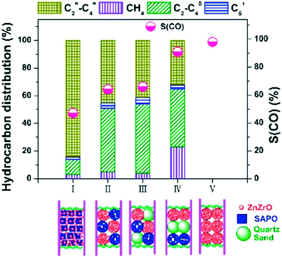 | ||
| Fig. 15 Over ZnZrO/SAPO. “Reprinted (adapted) with permission from Z. Li, J. Wang, Y. Qu, H. Liu, C. Tang, S. Miao, Z. Feng, H. An and C. Li, ACS Catal., 2017, 7, 8544–8548. Copyright (2017) American Chemical Society”. | ||
4. Kinetic modeling
Detailed knowledge of the performance and mechanisms of CO2 hydrogenation reactions can be obtained from kinetic modeling. The kinetic models can have widely different levels of detail and are mainly based on different approximations related to the rate determining steps and the nature of surface intermediates of the reaction.4.1 Kinetics of CO2 hydrogenation to methanol
In continuation of the discussion about the reaction intermediates and mechanisms related to copper-based and different oxide-based catalysts in sections 2.1.1 and 2.1.2, in this section, an overview of the kinetic models for the synthesis of methanol from CO2 hydrogenation will be discussed in detail. Methanol is produced on an industrial scale from synthesis gas mixtures consisting of CO/CO2/H2 over commercial Cu/ZnO/Al2O3 catalysts under typical reaction conditions of 503–553 K and 5–12 MPa.133 Kinetic modeling for methanol synthesis has been conducted for many years. Initially, most of the kinetic studies focused on macrokinetic modeling based on the Langmuir–Hinshelwood mechanism over Cu–Zn–Al catalysts. Later, the increasing efficiency of DFT and other electronic structure modeling techniques has led to the development of sophisticated microkinetic models with the introduction of kinetic equations including concentration and temperature effects using the DFT results as an initiation point for the estimation of model parameters.Different types of kinetic models for methanol synthesis have been reported in the literature.242–245 Some older models have mostly focused on methanol synthesis from CO over copper-based catalysts, whereas newer studies focus mainly on direct hydrogenation of CO2 to form methanol. Villa et al. used the Langmuir–Hinshelwood technique considering the non-dissociative adsorption of CO and H2 to model the kinetics of methanol synthesis at low pressure from carbon monoxide and hydrogen over a Cu/ZnO/Al2O3 catalyst.246 A kinetic model that quantitatively described the influence of concentration of carbon dioxide on methanol synthesis was introduced by Klier et al.247 They proposed that the highest rate can be obtained by a balance between the promoting effect of CO2 that can maintain the catalyst in an active state via its oxidizing ability and the decelerating effect from the strong adsorption of CO, when present at higher concentrations.247 Later, a comprehensive kinetic study on methanol synthesis at low pressure utilizing CO, CO2 and hydrogen over a Cu/ZnO/Al2O3 catalyst was introduced by Graaf et al.248 which later has been refitted and reused by several other authors to understand their models with rates calculated under industrial conditions with commercially available catalysts.100,247,249–251 Graaf et al.248 explained their experimental results for methanol synthesis kinetics using a two-site Langmuir–Hinshelwood mechanism depending on dissociative hydrogen adsorption and three independent overall reactions: methanol synthesis from CO and CO2 and the reverse water gas shift reaction. The results from the model suggested that methanol could be formed from both CO and CO2, and that hydrogen was adsorbed dissociatively. One site was devoted to the competitive adsorption of CO and CO2, while the other site was committed to the competitive adsorption of H2 and water. The adsorption of methanol was supposed to be insignificant. The reactions were studied in a spinning basket reactor at a pressure of 15–50 bar and temperature of 483–518 K.248,252,253
A recent study by Diaz et al. shows the kinetics of CO2 hydrogenation to methanol at atmospheric pressure utilizing a Pd–Cu–Zn/SiC catalyst. They developed three types of Langmuir–Hinshelwood (LH) kinetic models where the adsorption term was changed accordingly (competitive vs. two-site vs. three-site adsorption mechanisms). The hydrogenation of formate has been proposed as the rate determining step. The first model considered competitive adsorption of the reactants on the catalyst surface, the second model considered Pd and ZnO as two different adsorption sites and finally a three-site kinetic model was suggested where PdZn or PdCu along with ZnO had been considered as the adsorption sites. Finally, the proposed models were compared, and proper model differentiation was performed. It was established that the three-site LH kinetic model bestowed the minimum unweighted residual sum of squares and satisfied all the confirmed restrictions and fitted well with the experimental results. Therefore, this was concluded to be the most suitable kinetic model.254 The reaction rate equations for methanol synthesis from CO2 and the RWGS reaction (eqn (8) and (9)) proposed by Díaz et al.254 are as follows:
CO2 hydrogenation:
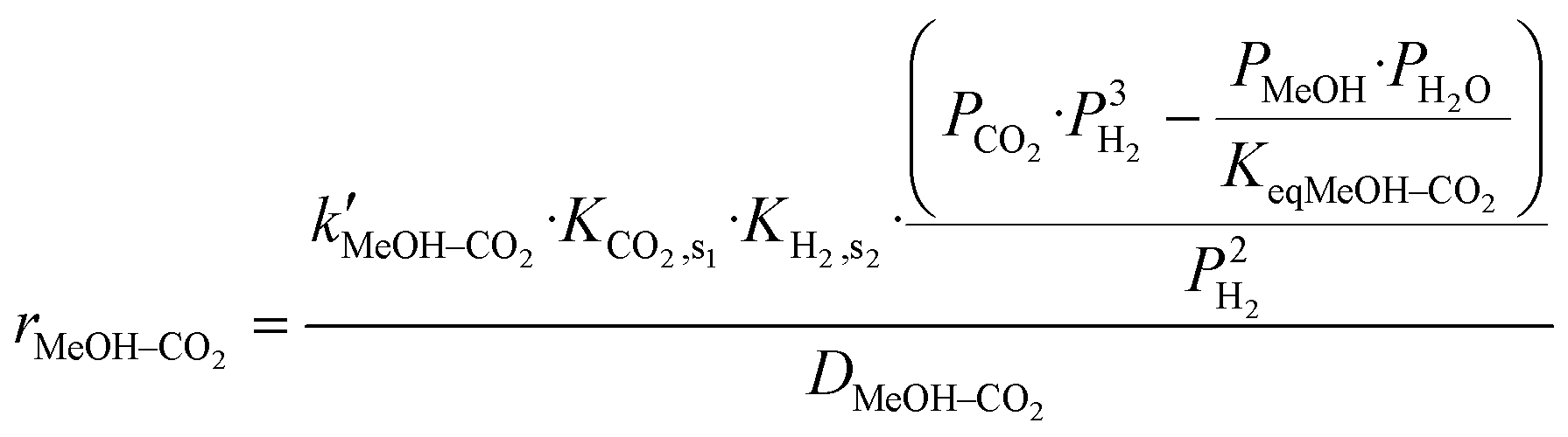 | (8) |
RWGS reaction:
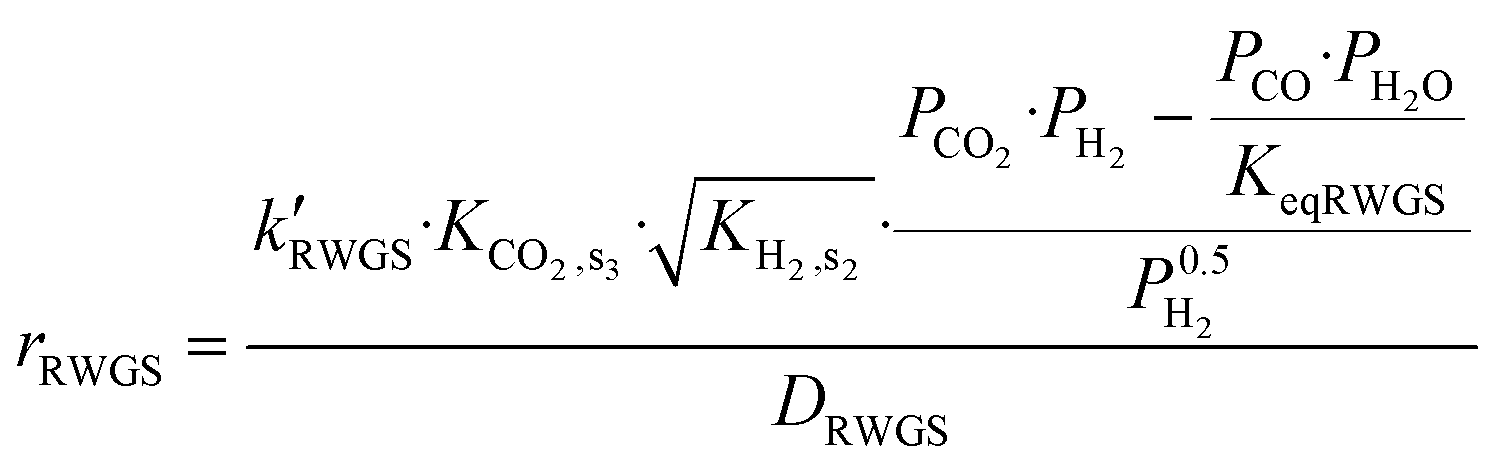 | (9) |
| Models | Conditions | Adsorption term |
|---|---|---|
| s = active sites. | ||
| Competitive adsorption | D MeOH–CO2 = DRWGS = Dx |
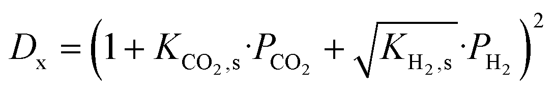
|
| s1 = s2 = s3 = s | ||
| Two-site mechanism | D MeOH–CO2 = DRWGS = Dx |
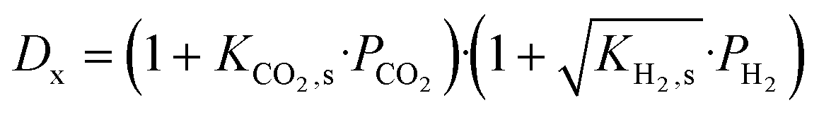
|
| s1 = s3 = s | ||
| Three-site mechanism | — |
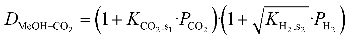
|
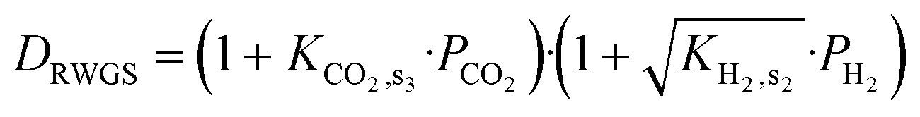
|
||
As mentioned above, recent studies have focused more on microkinetic modeling for methanol synthesis from CO2 hydrogenation considering various presumptions regarding the mechanism and the rate determining steps. A detailed mean-field microkinetic model for methanol synthesis and water–gas-shift reactions that included reaction intermediates e.g. HCOOH* and  and allowed for the development of formic acid (HCOOH), formaldehyde (CH2O), and methyl formate (HCOOCH3) as byproducts has been considered by Grabow and Mavrikakis.133 All the initial model parameters were deduced from periodic density functional theory (DFT) calculations on the Cu (111) surface and thereafter fitted to the experimental results performed under standard conditions using a Cu/ZnO/Al2O3 catalyst. It was observed that the WGS reaction mainly proceeds following the carboxyl pathway (that was explained above in sections 2.1.1. and 2.1.2) whereas both CO and CO2 hydrogenation pathways are mostly operative for methanol synthesis.133
Indium oxide has been considered as a highly efficient catalyst for methanol synthesis by direct CO2 hydrogenation as discussed in section 2.2. Pérez-Ramírez et al.159 explained in detail the mechanistic and kinetic aspects of CO2 hydrogenation on In2O3. Microkinetic modeling based on DFT simulations performed on In2O3(111) supplied values for temperature and concentration-dependent rate expressions, which were shown to be in good agreement with the experimental results. Microkinetic simulations were used to predict apparent activation energies and reaction orders and these agreed well with the experimental measurements. This is the only report, to date, on the kinetic modeling for CO2 hydrogenation based on an indium oxide catalyst.159 Another mean-field microkinetic model was used to forecast the reaction kinetics of different catalyst compositions on CO2 hydrogenation, based on 33 reversible preliminary steps.255 The model incorporates all the reaction pathways as calculated utilizing DFT without any assumptions on the rate determining step. First-principles multiscale modeling was achieved for a commercial-like catalyst (Zn3O3/Cu) and three other Cu/metal oxide-based catalysts (Cr3O3/Cu, Fe3O3/Cu, and Mg3O3/Cu). From the micro-kinetic modeling, methanol selectivity and conversion were acquired for each of the catalysts under various experimental conditions.255 Apart from the well-reported static microkinetic models, a dynamic microkinetic model for methanol synthesis was proposed by Norskov et al. over a Cu/ZnO catalyst. The model contains the dynamic changes in particle morphology and the active surface area and also describes the kinetic behaviour under transient conditions.249
Having discussed both macro- as well as micro-kinetic modeling techniques for CO2 hydrogenation to methanol, it is necessary to discuss the strengths and weaknesses of these modeling techniques. Macro-kinetic modeling deals with simple models built on power law kinetics or empirical Langmuir–Hinshelwood–Hougen–Watson (LHHW) kinetics predict reaction rates directly from the composition of the feed gas, temperature and pressure. Macrokinetic modeling is very practical and highly used in designing chemical reactors, quality control in catalyst synthesis, evaluating catalyst preferences and studies of catalyst deactivation. The models used in macro-kinetic calculations are therefore very robust for the fitting of kinetic data. However, the robustness that makes them so practical when used as empirical expressions makes them less useful for the determination of the mechanism of the reactions. These models do not explain the elementary reaction steps at the molecular level and different model formulations can often adequately describe the same experimental data. Therefore, a more comprehensive inspection of the reaction kinetics can be performed using microkinetic modeling, where an elementary reaction scheme and the molecular states of reactants and intermediates are utilized in simulating the reaction at the molecular level.256 Also, kinetic parameters in microkinetic models (like preexponential factors and activation energies) can be predicted from quantum mechanical modeling methods like DFT calculations. These aid in the identification of possible rate determining steps. The verification of microkinetic models depends on more elaborate surface measurement techniques and hence they can potentially make accurate predictions over a wide range of reaction conditions. Microkinetic modeling is computationally more demanding and hence not as robust as macrokinetic modeling. Hence both the modeling techniques have their importance in their own ways and are therefore considered significant in studying the kinetic modeling for catalytic hydrogenation reactions.
4.2 Kinetics of CO2 hydrogenation from methanol to hydrocarbons
Section 2.2.1 introduced the basic conceptual mechanisms behind the MTH reactions; in this section, we discuss how they are formulated in terms of rate expressions with varying detail. Kinetic modeling of MTH reactions has been studied over many years mostly over ZSM-5 and SAPO. The incorporation of C6+ compounds in the models with the ZSM-5 zeolite marks the difference between the models based on ZSM-5 and SAPO.Detailed kinetic models were formulated by Froment et al.257,258 for the methanol to olefins (MTO) conversion over HZSM-5 catalysts with a Si/A1 molar ratio of 200. The primary products (ethylene and propylene) formed from methanol and DME were modeled accurately using the Hougen–Watson model. The emergence of higher olefins was demonstrated with the help of the carbenium ion mechanism. The Evans–Polanyi relation was used to determine the activation energies of each step that considers the different energy levels of the carbenium ions and the olefin isomers.257 In a continuation of this work, the authors tested eight kinetic models based on the fundamental steps for the conversion of methanol via dimethyl ether into olefins and determined 33 parameters. Nonlinear regression was used to minimize the function used for parameter estimation.258 Zhou et al.259 worked with ethylene, propylene, and n-butylene over the SAPO-34 catalyst at 723 K using a fixed-bed reactor with a weight hourly space velocity (WHSV) varying from 1 to 424 h−1. The proposed kinetic model showed that the olefin concentrations were in equilibrium using a carbenium intermediate lump. The model was able to predict their results adequately.259
Gayubo et al. presented extensive modeling on MTO reaction kinetics with SAPO catalysts.260–263 They proposed a kinetic model for the conversion of methanol to olefins over a SAPO-34 catalyst and further extended their studies on a SAPO-18 catalyst for a wide range of experimental conditions. Fig. 16 shows the kinetic reaction scheme for the methanol to olefins process that is used by Gayubo et al.262 The kinetic model consists of three basic steps that develop gradually over time: an initiation period (formation of the active intermediate compounds), olefin formation, and finally deactivation stage (coke formation). Through this kinetic model, the authors predicted the experimental progress of the formation of olefins with time. Initially the production rate increases, later it passes through a maximum, where the concentration of the active intermediates reaches the maximum, followed by a reduction when deactivation causes a degeneration of the intermediates to form coke.260–263 The same group also proposed a kinetic model including the effect of water on the MTG reaction kinetics on the HZSM-5 catalyst. They further extended the study by considering the effect of water in the kinetic model for catalyst deactivation.264,265
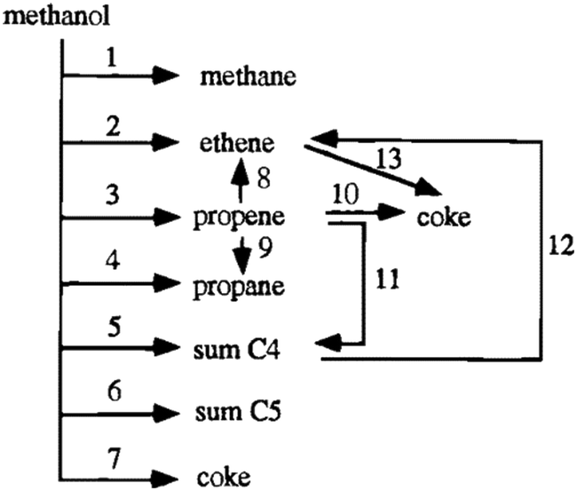 | ||
| Fig. 16 Kinetic scheme proposed by Bos et al.268 for transformation of methanol on SAPO-34. Reprinted (adapted) with permission from A. G. Gayubo, A. T. Aguayo, A. E. Sánchez del Campo, A. M. Tarrío and J. Bilbao, Ind. Eng. Chem. Res., 2000, 39, 292–300, Copyright (2000) American Chemical Society. | ||
On the basis of the hydrocarbon pool mechanism (as explained in section 2.2.1.2), Kaarsholm et al.266 proposed a model in which high molecular weight hydrocarbons were formed along with olefins inside the pores of the catalysts. The MTO reaction was studied for a phosphorus modified ZSM-5 catalyst in a fluidized bed reactor. The model involved 15 main reaction steps where, at equilibrium, all olefins are formed inside the pores of the catalyst. Fig. 17A shows the schematic for the reactions accounted for in this model by Kaarsholm et al.266 This model fits well with the experimental data for the olefins but requires modifications in the case of paraffin and C6+ species (Fig. 17B). The olefinic species formed as products all through the temperature interval explored were well verified by the model.266 Recently a new lumped kinetic model was established by Ryu et al.267 with 9 reactions consisting of 7 lumps of products and intermediates that include methane, ethylene, propylene, butenes, propane, C4 (that includes butane and 1,3-butadiene) and C5+ (including hydrocarbons with five or more carbon atoms and ethane) to investigate the catalytic activity of SAPO-34 for MTO reactions under various process conditions. This simple kinetic model is based on the hydrocarbon pool mechanism that has been developed from a detailed kinetic model by Bos et al.268 The model is developed based on the assumption that all the reaction rate expressions are first order.267
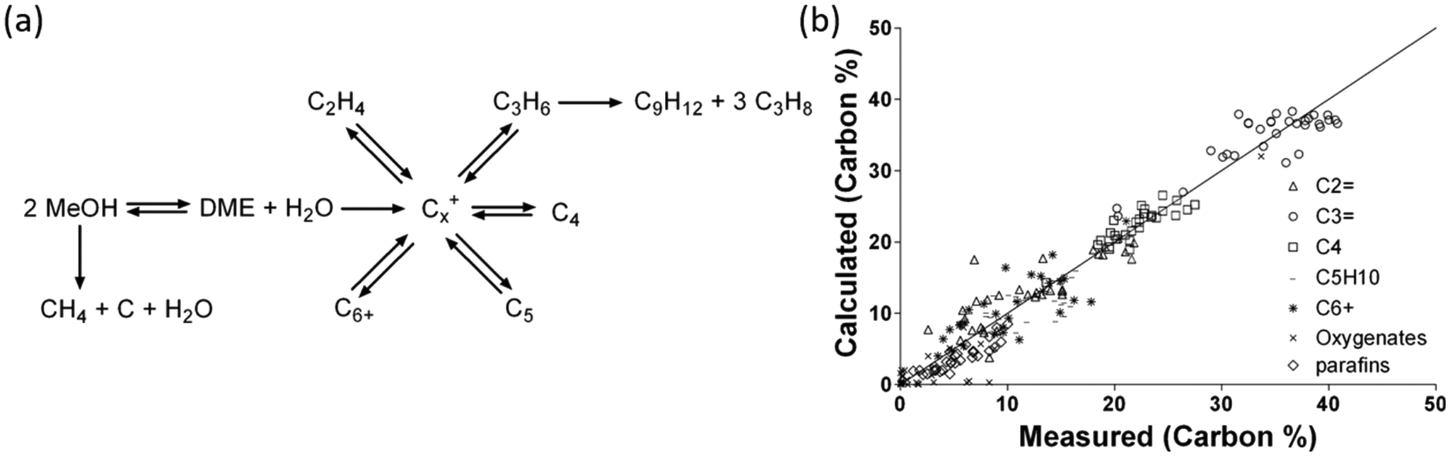 | ||
| Fig. 17 (a) Schematic drawing of the kinetic model and (b) parity plot showing the comparison of the calculated product distribution to the measured data by Kaarsholm et al. Reprinted (adapted) with permission from M. Kaarsholm, B. Rafii, F. Joensen, R. Cenni, J. Chaouki and G. S. Patience, Ind. Eng. Chem. Res., 2010, 49, 29–38, Copyright (2010) American Chemical Society. | ||
4.3 Kinetics of direct CO2 hydrogenation using bifunctional catalysts
To increase the CO2 conversion rate to methanol by coupling with MTO reactions, direct CO2 hydrogenation using bifunctional catalysts has become recently prominent as described in section 3. But there are, to our knowledge, no kinetic modeling studies, as such, for direct CO2 hydrogenation to hydrocarbons with methanol as an intermediate. It would seem possible to combine the standard models for CO2 hydrogenation to methanol and MTO (as discussed in sections 4.1 and 4.2 in detail) together to describe the performance of the direct CO2 hydrogenation procedure. However, it is noted from the experimental studies, as discussed in section 3.1, that with direct CO2 hydrogenation, the performance of the combined catalyst was greater than the sum of the individual catalysts. Perhaps, this is due simply to coupling the reactions and its favourable effect on methanol synthesis thermodynamics perhaps, or there are other combined synergy effects of the catalysts. It was, for example, presumed that for Cr2O3/HZSM-5, this combination of catalysts allowed the surface diffusion of methanol intermediates from the oxide to the zeolite. A kinetic modeling study could be used to explore these possibilities and to identify possibly improved operating conditions for direct CO2 hydrogenation.5. Conclusion and future perspectives
Urgent action is needed in terms of decreasing CO2 emissions in order to mitigate the challenges given by global warming. Currently, one promising action is to capture CO2 and recycle it to useful chemicals and fuels. In this review, we have summarized the recent progress in producing chemicals and fuels, like methanol and hydrocarbons, by using CO2 as a feedstock. The most studied reactions are the catalytic hydrogenation of CO2 to methanol and hydrocarbons. In the case of indirect production of hydrocarbons, the CO2 to methanol conversion is explored on Cu, Pd, Pt, Zn, In, Ga, Ag, Au, ZnO, In2O3, Ga2O3 and ZrO2. Methanol synthesis from CO2 is facing some challenges such as the excessive formation of CO which affects the selectivity for the desired product. There are many aspects where future research could be focused, for example, increasing the yield of fuels and chemicals by catalyst development; the uncertainty about the intermediates on the surface of the catalysts; the exact role of support materials; mechanisms of catalyst deactivation; interface composition; structure of active sites if catalysts have more than one active site for example in the case of bimetallic catalysts and when the support material also contains an active site; and different types of modelling such as kinetic modelling.In recent years, advanced developments have been made by various research groups by developing bifunctional catalysts to convert CO2 to hydrocarbons and fuels. In the case of bifunctional catalysts, two different catalysts are combined to form hydrocarbons in a one stage process. The mechanism, preparation methods and proximity effects were discussed using various in situ experiments and DFT studies. It has been seen that the intimate contact between the catalysts could increase the selectivity for hydrocarbons but the mechanism for this is unclear as intimate intra-particle contact was found to be negative in a few studies. In a few studies, it was concluded that close contact helped to promote the timely diffusion of methanol into zeolites and this increased the selectivity for hydrocarbons while in other studies the zeolites were poisoned by the metal/metal-oxide catalyst used for methanol synthesis. Thus, it is difficult to say exactly what proximity between the catalyst materials is optimal for the highest selectivity and conversion. The thermodynamics and reaction kinetics are different for the reactions (CO2 to methanol and MTH) as the active site needs different temperatures for the activation of CO2 and C–C coupling. A mean temperature, that is somewhere between the temperature most often used and favorable for the individual methanol synthesis and MTH processes, was used in recent reports for the activation of the catalysts. However, the temperature was found a limiting factor for bifunctional catalysts as higher temperature is favorable for the RWGS reaction and CO2 activation whereas low temperature decreases the CO2 conversion. Yet, studies have shown that the two reactions could be coupled efficiently to produce hydrocarbons from CO2 in a single step. Moreover, it was noticed that the lifetime of zeolite catalysts in the MTH reaction could be slightly improved in the presence of H2, CO2 and H2O co-feeds, which are the reactants and byproducts of the CO2 to methanol reaction step. A suitable choice/modification of the zeolite catalyst could be used to steer the production of hydrocarbons of different carbon numbers.
Most of the studies reported that a decrease in the selectivity for CO and CH4 could be achieved for bifunctional catalysts due to a synergetic interaction between both catalysts. But the mechanism and factors behind this are still unclear and deserve further research. However, bifunctional catalysts suffer from a low one-pass conversion efficiency and high selectivity towards CO in the case of direct synthesis. Also, the reported methanol selectivity in most studies for bi-functional systems is zero or very minimal and thus it can be concluded that for many systems it is possible to operate under conditions such that the rate of conversion of CO2 and CO to methanol is limiting, whereas the conversion of methanol to hydrocarbons is relatively fast. Thus, it is possible for the equilibrium limitations for the methanol synthesis reaction to be avoided, which can be a factor allowing for somewhat lower selectivity for CO as compared to the process without further conversion of methanol to hydrocarbons. There is a gap in understanding of the mechanism after methanol synthesis and before C–C coupling in the case of bifunctional catalysts that needs to be addressed. For example, more than one intermediate is observed on the surface of catalysts but only one of them is likely responsible for forming the product, so it is unclear what the rest of the intermediates form and what/how they affect the selectivity and activity of the catalyst. In most cases, the selectivity for longer hydrocarbons is very low due to kinetic limitations of the C–C coupling. Efforts could focus to producing longer hydrocarbons from these bifunctional catalysts by modifications in catalyst structure and composition, changing the synthesis method of catalysts, and modifications in the packing method to obtain an efficient contact between both catalysts. We have assessed the reaction kinetics of both CO2 to methanol and MTO reactions with a view of developing new kinetic models that couple these reactions and their catalysts for direct CO2 hydrogenation to higher hydrocarbons with methanol as an intermediate, which warrants investigation.
Thus, we suggest that further research could emphasize the development of highly active catalysts for methanol synthesis as well as selective hydrocarbon synthesis and higher CO2 conversion under industrially relevant conditions with better understanding of the fundamental activity–structure–composition relationship in bifunctional catalysts.
Conflicts of interest
There are no conflicts to declare.Acknowledgements
We would like to acknowledge the funding from the Swedish Energy Agency (P47450-1).References
- J. Rogelj, M. Den Elzen, N. Höhne, T. Fransen, H. Fekete, H. Winkler, R. Schaeffer, F. Sha, K. Riahi and M. Meinshausen, Nature, 2016, 534, 631–639 CrossRef CAS PubMed.
- S. J. Davis, K. Caldeira and H. D. Matthews, Science, 2010, 329, 1330–1333 CrossRef CAS PubMed.
- G. Energy, International Energy Agency: Paris, France, 2018 Search PubMed.
- G. A. Olah, G. S. Prakash and A. Goeppert, J. Am. Chem. Soc., 2011, 133, 12881–12898 CrossRef CAS PubMed.
- S. Brynolf, M. Taljegard, M. Grahn and J. Hansson, Renewable Sustainable Energy Rev., 2018, 81, 1887–1905 CrossRef.
- E. V. Kondratenko, G. Mul, J. Baltrusaitis, G. O. Larrazábal and J. Pérez-Ramírez, Energy Environ. Sci., 2013, 6, 3112–3135 RSC.
- J. Hansson, R. Hackl, M. Taljegard, S. Brynolf and M. Grahn, Front. Energy Res., 2017, 5, 4 Search PubMed.
- K. M. K. Yu, I. Curcic, J. Gabriel and S. C. E. Tsang, ChemSusChem, 2008, 1, 893–899 CrossRef CAS PubMed.
- D. Y. Leung, G. Caramanna and M. M. Maroto-Valer, Renewable Sustainable Energy Rev., 2014, 39, 426–443 CrossRef CAS.
- R. L. Newmark, S. J. Friedmann and S. A. Carroll, Environ. Manage., 2010, 45, 651–661 CrossRef PubMed.
- C. M. Oldenburg, Greenhouse Gases: Sci. Technol., 2012, 2, 1–2 CrossRef.
- W. Seifritz, Nature, 1990, 345, 486–486 CrossRef.
- S. C. Roy, O. K. Varghese, M. Paulose and C. A. Grimes, ACS Nano, 2010, 4, 1259–1278 CrossRef CAS PubMed.
- E. Alper and O. Y. Orhan, Petroleum, 2017, 3, 109–126 CrossRef.
- S. E. Hosseini and M. A. Wahid, Renewable Sustainable Energy Rev., 2016, 57, 850–866 CrossRef CAS.
- M. Liu, Y. Yi, L. Wang, H. Guo and A. Bogaerts, Catalysts, 2019, 9, 275 CrossRef.
- M. Fujiwara, R. Kieffer, H. Ando and Y. Souma, Appl. Catal., A, 1995, 121, 113–124 CrossRef CAS.
- S. Abelló and D. Montané, ChemSusChem, 2011, 4, 1538–1556 CrossRef PubMed.
- R.-P. Ye, J. Ding, W. Gong, M. D. Argyle, Q. Zhong, Y. Wang, C. K. Russell, Z. Xu, A. G. Russell and Q. Li, Nat. Commun., 2019, 10, 1–15 CrossRef PubMed.
- H. Yang, C. Zhang, P. Gao, H. Wang, X. Li, L. Zhong, W. Wei and Y. Sun, Catal. Sci. Technol., 2017, 7, 4580–4598 RSC.
- Z. Ma and M. D. Porosoff, ACS Catal., 2019, 9, 2639–2656 CrossRef CAS.
- M. M.-J. Li and S. C. E. Tsang, Catal. Sci. Technol., 2018, 8, 3450–3464 RSC.
- I. U. Din, M. S. Shaharun, M. A. Alotaibi, A. I. Alharthi and A. Naeem, J. CO2 Util., 2019, 34, 20–33 CrossRef CAS.
- A. Álvarez, A. Bansode, A. Urakawa, A. V. Bavykina, T. A. Wezendonk, M. Makkee, J. Gascon and F. Kapteijn, Chem. Rev., 2017, 117, 9804–9838 CrossRef PubMed.
- S. Dang, H. Yang, P. Gao, H. Wang, X. Li, W. Wei and Y. Sun, Catal. Today, 2019, 330, 61–75 CrossRef CAS.
- M. Aresta, A. Dibenedetto and A. Angelini, Chem. Rev., 2013, 114, 1709–1742 CrossRef PubMed.
- W. Li, H. Wang, X. Jiang, J. Zhu, Z. Liu, X. Guo and C. Song, RSC Adv., 2018, 8, 7651–7669 RSC.
- V. Ipatieff and G. Monroe, J. Am. Chem. Soc., 1945, 67, 2168–2171 CrossRef CAS.
- M. Behrens, Angew. Chem., Int. Ed., 2016, 55, 14906–14908 CrossRef CAS PubMed.
- K.-i. Tominaga, Y. Sasaki, T. Watanabe and M. Saito, Bull. Chem. Soc. Jpn., 1995, 68, 2837–2842 CrossRef CAS.
- S. Bebelis, H. Karasali and C. Vayenas, Solid State Ionics, 2008, 179, 1391–1395 CrossRef CAS.
- D. Theleritis, M. Makri, S. Souentie, A. Caravaca, A. Katsaounis and C. G. Vayenas, ChemElectroChem, 2014, 1, 254–262 CrossRef.
- M. Hoque and M. Guzman, Materials, 2018, 11, 1990 CrossRef PubMed.
- K. Li, B. Peng and T. Peng, ACS Catal., 2016, 6, 7485–7527 CrossRef CAS.
- M. Mikkelsen, M. Jørgensen and F. C. Krebs, Energy Environ. Sci., 2010, 3, 43–81 RSC.
- S. G. Jadhav, P. D. Vaidya, B. M. Bhanage and J. B. Joshi, Chem. Eng. Res. Des., 2014, 92, 2557–2567 CrossRef CAS.
- J. Wu, M. Saito, M. Takeuchi and T. Watanabe, Appl. Catal., A, 2001, 218, 235–240 CrossRef CAS.
- Y. Jiang, H. Yang, P. Gao, X. Li, J. Zhang, H. Liu, H. Wang, W. Wei and Y. Sun, J. CO2 Util., 2018, 26, 642–651 CrossRef CAS.
- C. Tisseraud, C. Comminges, A. Habrioux, S. Pronier, Y. Pouilloux and A. Le Valant, Mol. Catal., 2018, 446, 98–105 CrossRef CAS.
- Y. Yang, J. Evans, J. A. Rodriguez, M. G. White and P. Liu, Phys. Chem. Chem. Phys., 2010, 12, 9909–9917 RSC.
- R. A. Köppel, C. Stöcker and A. Baiker, J. Catal., 1998, 179, 515–527 CrossRef.
- A. García-Trenco, A. Regoutz, E. R. White, D. J. Payne, M. S. Shaffer and C. K. Williams, Appl. Catal., B, 2018, 220, 9–18 CrossRef.
- S. Li, Y. Wang, B. Yang and L. Guo, Appl. Catal., A, 2019, 571, 51–60 CrossRef CAS.
- K. Sun, Z. Fan, J. Ye, J. Yan, Q. Ge, Y. Li, W. He, W. Yang and C.-j. Liu, J. CO2 Util., 2015, 12, 1–6 CrossRef CAS.
- R. Guil-López, N. Mota, J. Llorente, E. Millán, B. Pawelec, J. Fierro and R. Navarro, Materials, 2019, 12, 3902 CrossRef PubMed.
- R. Koeppel, A. Baiker and A. Wokaun, Appl. Catal., A, 1992, 84, 77–102 CrossRef CAS.
- T. Fujitani, M. Saito, Y. Kanai, M. Takeuchi, K. Moriya, T. Watanabe, M. Kawai and T. Kakumoto, Chem. Lett., 1993, 22, 1079–1080 CrossRef.
- M. Kilo, J. Weigel, A. Wokaun, R. Koeppel, A. Stoeckli and A. Baiker, J. Mol. Catal. A: Chem., 1997, 126, 169–184 CrossRef CAS.
- A. Erdöhelyi, M. Pásztor and F. Solymosi, J. Catal., 1986, 98, 166–177 CrossRef.
- L. Fan and K. Fujimoto, Appl. Catal., A, 1993, 106, L1–L7 CrossRef CAS.
- T. Fujitani, M. Saito, Y. Kanai, T. Watanabe, J. Nakamura and T. Uchijima, Appl. Catal., A, 1995, 125, L199–L202 CrossRef CAS.
- X. Jiang, N. Koizumi, X. Guo and C. Song, Appl. Catal., B, 2015, 170, 173–185 CrossRef.
- M. R. Gogate and R. J. Davis, Catal. Commun., 2010, 11, 901–906 CrossRef CAS.
- E. L. Fornero, P. B. Sanguineti, D. L. Chiavassa, A. L. Bonivardi and M. A. Baltanás, Catal. Today, 2013, 213, 163–170 CrossRef CAS.
- J. Słoczyński, R. Grabowski, P. Olszewski, A. Kozłowska, J. Stoch, M. Lachowska and J. Skrzypek, Appl. Catal., A, 2006, 310, 127–137 CrossRef.
- N. Pasupulety, H. Driss, Y. A. Alhamed, A. A. Alzahrani, M. A. Daous and L. Petrov, Appl. Catal., A, 2015, 504, 308–318 CrossRef CAS.
- L. BASF, Germany, https://www.basf.com/global/en/who-we-are/history/chronology/1902-1924.html.
- D. Sheldon, Johnson Matthey Technol. Rev., 2017, 61, 172–182 CrossRef CAS.
- M. Behrens, S. Zander, P. Kurr, N. Jacobsen, J. r. Senker, G. Koch, T. Ressler, R. W. Fischer and R. Schlögl, J. Am. Chem. Soc., 2013, 135, 6061–6068 CrossRef CAS PubMed.
- P. Davies, F. F. Snowdon, G. W. Bridger, D. O. Hughes and P. W. Young, U.K. Pat., GB1010871, 1962 Search PubMed.
- J. T. Gallagher and J. M. Kidd, U.K. Pat., GB 1159035, 1969 Search PubMed.
- F. Studt, M. Behrens, E. L. Kunkes, N. Thomas, S. Zander, A. Tarasov, J. Schumann, E. Frei, J. B. Varley and F. Abild-Pedersen, ChemCatChem, 2015, 7, 1105–1111 CrossRef CAS.
- E. L. Kunkes, F. Studt, F. Abild-Pedersen, R. Schlögl and M. Behrens, J. Catal., 2015, 328, 43–48 CrossRef CAS.
- J. Liu, J. Shi, D. He, Q. Zhang, X. Wu, Y. Liang and Q. Zhu, Appl. Catal., A, 2001, 218, 113–119 CrossRef CAS.
- T. Fujitani, M. Saito, Y. Kanai, T. Kakumoto, T. Watanabe, J. Nakamura and T. Uchijima, Catal. Lett., 1994, 25, 271–276 CrossRef CAS.
- C. Tisseraud, C. Comminges, S. Pronier, Y. Pouilloux and A. Le Valant, J. Catal., 2016, 343, 106–114 CrossRef CAS.
- T. Lunkenbein, J. Schumann, M. Behrens, R. Schlögl and M. G. Willinger, Angew. Chem., Int. Ed., 2015, 54, 4544–4548 CrossRef CAS PubMed.
- H. Lei, R. Nie, G. Wu and Z. Hou, Fuel, 2015, 154, 161–166 CrossRef CAS.
- F. Liao, Y. Huang, J. Ge, W. Zheng, K. Tedsree, P. Collier, X. Hong and S. C. Tsang, Angew. Chem., Int. Ed., 2011, 50, 2162–2165 CrossRef CAS PubMed.
- J. Sun, G. Yang, Q. Ma, I. Ooki, A. Taguchi, T. Abe, Q. Xie, Y. Yoneyama and N. Tsubaki, J. Mater. Chem. A, 2014, 2, 8637–8643 RSC.
- S. Kuld, M. Thorhauge, H. Falsig, C. F. Elkjær, S. Helveg, I. Chorkendorff and J. Sehested, Science, 2016, 352, 969–974 CrossRef CAS PubMed.
- J. Toyir, R. Miloua, N. Elkadri, M. Nawdali, H. Toufik, F. Miloua and M. Saito, Phys. Procedia, 2009, 2, 1075–1079 CrossRef CAS.
- O. Martin, C. Mondelli, D. Curulla-Ferré, C. Drouilly, R. Hauert and J. Pérez-Ramírez, ACS Catal., 2015, 5, 5607–5616 CrossRef CAS.
- M. Behrens, F. Studt, I. Kasatkin, S. Kühl, M. Hävecker, F. Abild-Pedersen, S. Zander, F. Girgsdies, P. Kurr and B.-L. Kniep, Science, 2012, 336, 893–897 CrossRef CAS PubMed.
- S. A. Kondrat, P. J. Smith, J. H. Carter, J. S. Hayward, G. J. Pudge, G. Shaw, M. S. Spencer, J. K. Bartley, S. H. Taylor and G. J. Hutchings, Faraday Discuss., 2017, 197, 287–307 RSC.
- N. Mota, R. Guil-Lopez, B. Pawelec, J. Fierro and R. Navarro, RSC Adv., 2018, 8, 20619–20629 RSC.
- R. Gaikwad, A. Bansode and A. Urakawa, J. Catal., 2016, 343, 127–132 CrossRef CAS.
- B. Tidona, C. Koppold, A. Bansode, A. Urakawa and P. R. von Rohr, J. Supercrit. Fluids, 2013, 78, 70–77 CrossRef CAS.
- A. Bansode and A. Urakawa, J. Catal., 2014, 309, 66–70 CrossRef CAS.
- C. Li, X. Yuan and K. Fujimoto, Appl. Catal., A, 2014, 469, 306–311 CrossRef CAS.
- J. Słoczyński, R. Grabowski, A. Kozłowska, P. Olszewski, J. Stoch, J. Skrzypek and M. Lachowska, Appl. Catal., A, 2004, 278, 11–23 CrossRef.
- R. Raudaskoski, M. V. Niemelä and R. L. Keiski, Top. Catal., 2007, 45, 57–60 CrossRef CAS.
- J. Toyir, P. R. r. de la Piscina, J. L. G. Fierro and N. s. Homs, Appl. Catal., B, 2001, 29, 207–215 CrossRef CAS.
- J. Toyir, P. R. r. de la Piscina, J. L. G. Fierro and N. s. Homs, Appl. Catal., B, 2001, 34, 255–266 CrossRef CAS.
- M. Lachowska and J. Skrzypek, React. Kinet. Catal. Lett., 2004, 83, 269–273 CrossRef CAS.
- X.-M. Liu, G. Lu and Z.-F. Yan, Appl. Catal., A, 2005, 279, 241–245 CrossRef CAS.
- J. B. Wang, H.-K. Lee and T.-J. Huang, Catal. Lett., 2002, 83, 79–86 CrossRef CAS.
- Z.-s. Hong, Y. Cao, J.-f. Deng and K.-n. Fan, Catal. Lett., 2002, 82, 37–44 CrossRef CAS.
- X. An, J. Li, Y. Zuo, Q. Zhang, D. Wang and J. Wang, Catal. Lett., 2007, 118, 264–269 CrossRef CAS.
- Y. Liu, Y. Zhang, T. Wang and N. Tsubaki, Chem. Lett., 2007, 36, 1182–1183 CrossRef CAS.
- F. Arena, K. Barbera, G. Italiano, G. Bonura, L. Spadaro and F. Frusteri, J. Catal., 2007, 249, 185–194 CrossRef CAS.
- X. Guo, D. Mao, S. Wang, G. Wu and G. Lu, Catal. Commun., 2009, 10, 1661–1664 CrossRef CAS.
- X. Guo, D. Mao, G. Lu, S. Wang and G. Wu, J. Catal., 2010, 271, 178–185 CrossRef CAS.
- E. Frei, A. Schaadt, T. Ludwig, H. Hillebrecht and I. Krossing, ChemCatChem, 2014, 6, 1721–1730 CrossRef CAS.
- L. Li, D. Mao, J. Yu and X. Guo, J. Power Sources, 2015, 279, 394–404 CrossRef CAS.
- L. Angelo, K. Kobl, L. M. M. Tejada, Y. Zimmermann, K. Parkhomenko and A.-C. Roger, C. R. Chim., 2015, 18, 250–260 CrossRef CAS.
- T. Witoon, J. Chalorngtham, P. Dumrongbunditkul, M. Chareonpanich and J. Limtrakul, Chem. Eng. J., 2016, 293, 327–336 CrossRef CAS.
- S. Kattel, B. Yan, Y. Yang, J. G. Chen and P. Liu, J. Am. Chem. Soc., 2016, 138, 12440–12450 CrossRef CAS PubMed.
- L. Angelo, M. Girleanu, O. Ersen, C. Serra, K. Parkhomenko and A.-C. Roger, Catal. Today, 2016, 270, 59–67 CrossRef CAS.
- J.-F. o. Portha, K. Parkhomenko, K. Kobl, A.-C. c. Roger, S. Arab, J.-M. Commenge and L. Falk, Ind. Eng. Chem. Res., 2017, 56, 13133–13145 CrossRef CAS.
- X.-L. Liang, X. Dong, G.-D. Lin and H.-B. Zhang, Appl. Catal., B, 2009, 88, 315–322 CrossRef CAS.
- S. E. Collins, M. A. Baltanás and A. L. Bonivardi, J. Catal., 2004, 226, 410–421 CrossRef CAS.
- S. E. Collins, J. J. Delgado, C. Mira, J. J. Calvino, S. Bernal, D. L. Chiavassa, M. A. Baltanás and A. L. Bonivardi, J. Catal., 2012, 292, 90–98 CrossRef CAS.
- X. Zhou, J. Qu, F. Xu, J. Hu, J. S. Foord, Z. Zeng, X. Hong and S. C. E. Tsang, Chem. Commun., 2013, 49, 1747–1749 RSC.
- J. Qu, X. Zhou, F. Xu, X.-Q. Gong and S. C. E. Tsang, J. Phys. Chem. C, 2014, 118, 24452–24466 CrossRef CAS.
- H. Bahruji, M. Bowker, G. Hutchings, N. Dimitratos, P. Wells, E. Gibson, W. Jones, C. Brookes, D. Morgan and G. Lalev, J. Catal., 2016, 343, 133–146 CrossRef CAS.
- A. Ota, E. L. Kunkes, I. Kasatkin, E. Groppo, D. Ferri, B. Poceiro, R. M. N. Yerga and M. Behrens, J. Catal., 2012, 293, 27–38 CrossRef CAS.
- Y. Hartadi, D. Widmann and R. J. Behm, ChemSusChem, 2015, 8, 456–465 CrossRef CAS PubMed.
- Y. Hartadi, D. Widmann and R. J. Behm, Phys. Chem. Chem. Phys., 2016, 18, 10781–10791 RSC.
- F. Studt, I. Sharafutdinov, F. Abild-Pedersen, C. F. Elkjær, J. S. Hummelshøj, S. Dahl, I. Chorkendorff and J. K. Nørskov, Nat. Chem., 2014, 6, 320–324 CrossRef CAS PubMed.
- C. Shao, L. Fan, K. Fujimoto and Y. Iwasawa, Appl. Catal., A, 1995, 128, L1–L6 CrossRef CAS.
- T. Iizuka, M. Kojima and K. Tanabe, J. Chem. Soc., Chem. Commun., 1983, 638–639 RSC.
- T. Inoue, T. Iizuka and K. Tanabe, Appl. Catal., 1989, 46, 1–9 CrossRef CAS.
- H. Kusama, K. K. Bando, K. Okabe and H. Arakawa, Appl. Catal., A, 2001, 205, 285–294 CrossRef CAS.
- H. Zhan, F. Li, P. Gao, N. Zhao, F. Xiao, W. Wei, L. Zhong and Y. Sun, J. Power Sources, 2014, 251, 113–121 CrossRef CAS.
- I. Kasatkin, P. Kurr, B. Kniep, A. Trunschke and R. Schlögl, Angew. Chem., Int. Ed., 2007, 46, 7324–7327 CrossRef CAS PubMed.
- M. Behrens, J. Catal., 2009, 267, 24–29 CrossRef CAS.
- I. Sharafutdinov, C. F. Elkjær, H. W. P. de Carvalho, D. Gardini, G. L. Chiarello, C. D. Damsgaard, J. B. Wagner, J.-D. Grunwaldt, S. Dahl and I. Chorkendorff, J. Catal., 2014, 320, 77–88 CrossRef CAS.
- Y. Hartadi, D. Widmann and R. J. Behm, J. Catal., 2016, 333, 238–250 CrossRef CAS.
- J. Xiao and T. Frauenheim, J. Phys. Chem. C, 2013, 117, 1804–1808 CrossRef CAS.
- K. Larmier, W. C. Liao, S. Tada, E. Lam, R. Verel, A. Bansode, A. Urakawa, A. Comas-Vives and C. Copéret, Angew. Chem., Int. Ed., 2017, 56, 2318–2323 CrossRef CAS.
- S.-i. Fujita, M. Usui, H. Ito and N. Takezawa, J. Catal., 1995, 157, 403–413 CrossRef CAS.
- L. Gao and C. Au, J. Catal., 2000, 189, 1–15 CrossRef CAS.
- Y. Yang, D. Mei, C. H. Peden, C. T. Campbell and C. A. Mims, ACS Catal., 2015, 5, 7328–7337 CrossRef CAS.
- M. D. Porosoff, B. Yan and J. G. Chen, Energy Environ. Sci., 2016, 9, 62–73 RSC.
- Y.-F. Zhao, Y. Yang, C. Mims, C. H. Peden, J. Li and D. Mei, J. Catal., 2011, 281, 199–211 CrossRef CAS.
- J. Tabatabaei, B. Sakakini and K. Waugh, Catal. Lett., 2006, 110, 77–84 CrossRef CAS.
- Y. Yang, C. A. Mims, R. S. Disselkamp, J.-H. Kwak, C. H. Peden and C. Campbell, J. Phys. Chem. C, 2010, 114, 17205–17211 CrossRef CAS.
- S. Kattel, P. J. Ramírez, J. G. Chen, J. A. Rodriguez and P. Liu, Science, 2017, 355, 1296–1299 CrossRef CAS PubMed.
- F. Arena, G. Italiano, K. Barbera, S. Bordiga, G. Bonura, L. Spadaro and F. Frusteri, Appl. Catal., A, 2008, 350, 16–23 CrossRef CAS.
- Y. Yang, C. A. Mims, D. Mei, C. H. Peden and C. T. Campbell, J. Catal., 2013, 298, 10–17 CrossRef CAS.
- H. Nakatsuji and Z. M. Hu, Int. J. Quantum Chem., 2000, 77, 341–349 CrossRef CAS.
- L. Grabow and M. Mavrikakis, ACS Catal., 2011, 1, 365–384 CrossRef CAS.
- X. Zhang, J.-X. Liu, B. Zijlstra, I. A. Filot, Z. Zhou, S. Sun and E. J. Hensen, Nano Energy, 2018, 43, 200–209 CrossRef CAS.
- K. Chen, H. Fang, S. Wu, X. Liu, J. Zheng, S. Zhou, X. Duan, Y. Zhuang, S. C. E. Tsang and Y. Yuan, Appl. Catal., B, 2019, 251, 119–129 CrossRef CAS.
- E. Lam, K. Larmier, P. Wolf, S. Tada, O. V. Safonova and C. Copéret, J. Am. Chem. Soc., 2018, 140, 10530–10535 CrossRef CAS PubMed.
- W. Wang, Y. Zhang, Z. Wang, J.-m. Yan, Q. Ge and C.-j. Liu, Catal. Today, 2016, 259, 402–408 CrossRef CAS.
- Q. Sun, J. Ye, C. j. Liu and Q. Ge, Greenh Gases, 2014, 4, 140–144 CrossRef CAS.
- J. Ye, Q. Ge and C.-j. Liu, Chem. Eng. Sci., 2015, 135, 193–201 CrossRef CAS.
- J. Ye, C. Liu and Q. Ge, J. Phys. Chem. C, 2012, 116, 7817–7825 CrossRef CAS.
- J. Ye, C. Liu, D. Mei and Q. Ge, ACS Catal., 2013, 3, 1296–1306 CrossRef CAS.
- O. Martin, A. J. Martín, C. Mondelli, S. Mitchell, T. F. Segawa, R. Hauert, C. Drouilly, D. Curulla-Ferré and J. Pérez-Ramírez, Angew. Chem., Int. Ed., 2016, 55, 6261–6265 CrossRef CAS.
- T.-y. Chen, C. Cao, T.-b. Chen, X. Ding, H. Huang, L. Shen, X. Cao, M. Zhu, J. Xu and J. Gao, ACS Catal., 2019, 9, 8785–8797 CrossRef CAS.
- W. Luo, W. Xie, M. Li, J. Zhang and A. Züttel, J. Mater. Chem. A, 2019, 7, 4505–4515 RSC.
- J. Ye, C.-j. Liu, D. Mei and Q. Ge, J. Catal., 2014, 317, 44–53 CrossRef CAS.
- N. Rui, Z. Wang, K. Sun, J. Ye, Q. Ge and C.-j. Liu, Appl. Catal., B, 2017, 218, 488–497 CrossRef CAS.
- J. Wang, G. Li, Z. Li, C. Tang, Z. Feng, H. An, H. Liu, T. Liu and C. Li, Sci. Adv., 2017, 3, e1701290 CrossRef PubMed.
- L. Yao, X. Shen, Y. Pan and Z. Peng, J. Catal., 2019, 372, 74–85 CrossRef CAS.
- N. Akkharaphatthawon, N. Chanlek, C. K. Cheng, M. Chareonpanich, J. Limtrakul and T. Witoon, Appl. Surf. Sci., 2019, 489, 278–286 CrossRef CAS.
- J. L. Snider, V. Streibel, M. A. Hubert, T. S. Choksi, E. Valle, D. C. Upham, J. Schumann, M. S. Duyar, A. Gallo and F. Abild-Pedersen, ACS Catal., 2019, 9, 3399–3412 CrossRef CAS.
- M. S. Frei, C. Mondelli, R. García-Muelas, K. S. Kley, B. Puértolas, N. López, O. V. Safonova, J. A. Stewart, D. C. Ferré and J. Pérez-Ramírez, Nat. Commun., 2019, 10, 1–11 CrossRef.
- Y.-L. Men, Y. Liu, Q. Wang, Z.-H. Luo, S. Shao, Y.-B. Li and Y.-X. Pan, Chem. Eng. Sci., 2019, 200, 167–175 CrossRef CAS.
- H. Jiang, J. Lin, X. Wu, W. Wang, Y. Chen and M. Zhang, J. CO2 Util., 2020, 36, 33–39 CrossRef CAS.
- A. R. Richard and M. Fan, ACS Catal., 2017, 7, 5679–5692 CrossRef CAS.
- A. R. Richard and M. Fan, Fuel, 2018, 222, 513–522 CrossRef CAS.
- M. Chen, J. Xu, Y.-M. Liu, Y. Cao, H.-Y. He and J.-H. Zhuang, Appl. Catal., A, 2010, 377, 35–41 CrossRef CAS.
- D. Liu, Y. Men, J. Wang, G. Kolb, X. Liu, Y. Wang and Q. Sun, Int. J. Hydrogen Energy, 2016, 41, 21990–21999 CrossRef CAS.
- C. Rameshan, H. Lorenz, L. Mayr, S. Penner, D. Zemlyanov, R. Arrigo, M. Haevecker, R. Blume, A. Knop-Gericke and R. Schlögl, J. Catal., 2012, 295, 186–194 CrossRef CAS PubMed.
- M. S. Frei, M. Capdevila-Cortada, R. García-Muelas, C. Mondelli, N. López, J. A. Stewart, D. C. Ferré and J. Pérez-Ramírez, J. Catal., 2018, 361, 313–321 CrossRef CAS.
- K. K. Ghuman, T. E. Wood, L. B. Hoch, C. A. Mims, G. A. Ozin and C. V. Singh, Phys. Chem. Chem. Phys., 2015, 17, 14623–14635 RSC.
- L. B. Hoch, T. E. Wood, P. G. O'Brien, K. Liao, L. M. Reyes, C. A. Mims and G. A. Ozin, Adv. Sci., 2014, 1, 1400013 CrossRef PubMed.
- A. Tsoukalou, P. M. Abdala, D. Stoian, X. Huang, M.-G. Willinger, A. Fedorov and C. R. Müller, J. Am. Chem. Soc., 2019, 141, 13497–13505 CrossRef CAS PubMed.
- T. Bielz, H. Lorenz, W. Jochum, R. Kaindl, F. Klauser, B. Klotzer and S. Penner, J. Phys. Chem. C, 2010, 114, 9022–9029 CrossRef CAS.
- A. Posada-Borbón and H. Grönbeck, Phys. Chem. Chem. Phys., 2019, 21, 21698–21708 RSC.
- C. D. Chang and A. J. Silvestri, J. Catal., 1977, 47, 249–259 CrossRef CAS.
- C. D. Chang, Catal. Rev.: Sci. Eng., 1983, 25, 1–118 CrossRef CAS.
- C. D. Chang, Catal. Today, 1992, 13, 103–111 CrossRef CAS.
- I. Yarulina, A. D. Chowdhury, F. Meirer, B. M. Weckhuysen and J. Gascon, Nat. Catal., 2018, 1, 398 CrossRef CAS.
- U. Olsbye, S. Svelle, M. Bjørgen, P. Beato, T. V. Janssens, F. Joensen, S. Bordiga and K. P. Lillerud, Angew. Chem., Int. Ed., 2012, 51, 5810–5831 CrossRef CAS PubMed.
- F. J. Keil, Microporous Mesoporous Mater., 1999, 29, 49–66 CrossRef CAS.
- P. Tian, Y. Wei, M. Ye and Z. Liu, ACS Catal., 2015, 5, 1922–1938 CrossRef CAS.
- V. Van Speybroeck, K. De Wispelaere, J. Van der Mynsbrugge, M. Vandichel, K. Hemelsoet and M. Waroquier, Chem. Soc. Rev., 2014, 43, 7326–7357 RSC.
- E. Kianfar, S. Hajimirzaee, S. S. Musavian and A. S. Mehr, Microchem. J., 2020, 104822 CrossRef CAS.
- W. Wang and M. Hunger, Acc. Chem. Res., 2008, 41, 895–904 CrossRef CAS PubMed.
- W. Wang, M. Seiler and M. Hunger, J. Phys. Chem. B, 2001, 105, 12553–12558 CrossRef CAS.
- X. Wu, S. Xu, W. Zhang, J. Huang, J. Li, B. Yu, Y. Wei and Z. Liu, Angew. Chem., Int. Ed., 2017, 56, 9039–9043 CrossRef CAS PubMed.
- J. Li, Z. Wei, Y. Chen, B. Jing, Y. He, M. Dong, H. Jiao, X. Li, Z. Qin and J. Wang, J. Catal., 2014, 317, 277–283 CrossRef CAS.
- A. D. Chowdhury, K. Houben, G. T. Whiting, M. Mokhtar, A. M. Asiri, S. A. Al-Thabaiti, S. N. Basahel, M. Baldus and B. M. Weckhuysen, Angew. Chem., Int. Ed., 2016, 55, 15840–15845 CrossRef CAS PubMed.
- R. Dessau and R. LaPierre, J. Catal., 1982, 78, 136–141 CrossRef CAS.
- I. M. Dahl and S. Kolboe, J. Catal., 1994, 149, 458–464 CrossRef CAS.
- B. Arstad and S. Kolboe, J. Am. Chem. Soc., 2001, 123, 8137–8138 CrossRef CAS.
- S. Svelle, F. Joensen, J. Nerlov, U. Olsbye, K.-P. Lillerud, S. Kolboe and M. Bjørgen, J. Am. Chem. Soc., 2006, 128, 14770–14771 CrossRef CAS PubMed.
- A. Hwang and A. Bhan, Acc. Chem. Res., 2019, 52, 2647–2656 CrossRef CAS PubMed.
- S. Kim, G. Park, M. H. Woo, G. Kwak and S. K. Kim, ACS Catal., 2019, 9, 2880–2892 CrossRef CAS.
- S. S. Arora, Z. Shi and A. Bhan, ACS Catal., 2019, 6407–6414 CrossRef CAS.
- Y. Bhawe, M. Moliner-Marin, J. D. Lunn, Y. Liu, A. Malek and M. Davis, ACS Catal., 2012, 2, 2490–2495 CrossRef CAS.
- G. Sastre, Front. Chem. Sci. Eng., 2016, 10, 76–89 CrossRef CAS.
- X. Li and J. Jiang, Phys. Chem. Chem. Phys., 2018, 20, 14322–14330 RSC.
- S. Teketel, M. W. Erichsen, F. L. Bleken, S. Svelle, K. P. Lillerud and U. Olsbye, Catalysis, 2014, 26, 179–217 CAS.
- S. Lee and M. Choi, J. Catal., 2019, 375, 183–192 CrossRef CAS.
- F. Goodarzi, I. P. Herrero, G. N. Kalantzopoulos, S. Svelle, A. Lazzarini, P. Beato, U. Olsbye and S. Kegnæs, Microporous Mesoporous Mater., 2020, 292, 109730 CrossRef CAS.
- S. S. Arora, D. L. Nieskens, A. Malek and A. Bhan, Nat. Catal., 2018, 1, 666–672 CrossRef CAS.
- S. Senger and L. Radom, J. Am. Chem. Soc., 2000, 122, 2613–2620 CrossRef CAS.
- R. Gounder and E. Iglesia, J. Catal., 2011, 277, 36–45 CrossRef CAS.
- X. Zhao, J. Li, P. Tian, L. Wang, X. Li, S. Lin, X. Guo and Z. Liu, ACS Catal., 2019, 9, 3017–3025 CrossRef CAS.
- L. Smith, A. Cheetham, R. Morris, L. Marchese, J. Thomas, P. Wright and J. Chen, Science, 1996, 271, 799–802 CrossRef CAS.
- J. C. Siria, M. Duran, A. Lledos and J. Bertran, J. Am. Chem. Soc., 1987, 109, 7623–7629 CrossRef CAS.
- I. G. Economou, Ind. Eng. Chem. Res., 2002, 41, 953–962 CrossRef CAS.
- A. T. Aguayo, A. G. Gayubo, A. M. Tarrío, A. Atutxa and J. Bilbao, J. Chem. Technol. Biotechnol., 2002, 77, 211–216 CrossRef CAS.
- A. Zachariou, A. Hawkins, D. Lennon, S. F. Parker, S. K. Matam, C. R. A. Catlow, P. Collier, A. Hameed, J. McGregor and R. F. Howe, Appl. Catal., A, 2019, 569, 1–7 CrossRef CAS.
- F. Magzoub, X. Li, J. Al-Darwish, F. Rezaei and A. A. Rownaghi, Appl. Catal., B, 2019, 245, 486–495 CrossRef CAS.
- H. Hernando, C. Ochoa-Hernández, M. Shamzhy, I. Moreno, J. Fermoso, P. Pizarro, J. M. Coronado, J. Čejka and D. P. Serrano, Catal. Sci. Technol., 2019, 9, 789–802 RSC.
- R. Bingre, R. Li, Q. Wang, P. Nguyen, T. Onfroy and B. Louis, Catalysts, 2019, 9, 545 CrossRef CAS.
- A. D. Chowdhury, I. Yarulina, E. Abou-Hamad, A. Gurinov and J. Gascon, Chem. Sci., 2019, 10, 8946–8954 RSC.
- Y. Shen, T. T. Le, D. Fu, J. E. Schmidt, M. Filez, B. M. Weckhuysen and J. D. Rimer, ACS Catal., 2018, 8, 11042–11053 CrossRef CAS.
- M. Choi, K. Na, J. Kim, Y. Sakamoto, O. Terasaki and R. Ryoo, Nature, 2009, 461, 246 CrossRef CAS PubMed.
- W. Dai, G. Wu, L. Li, N. Guan and M. Hunger, ACS Catal., 2013, 3, 588–596 CrossRef CAS.
- B. P. Hereijgers, F. Bleken, M. H. Nilsen, S. Svelle, K.-P. Lillerud, M. Bjørgen, B. M. Weckhuysen and U. Olsbye, J. Catal., 2009, 264, 77–87 CrossRef CAS.
- D. Chen, K. Moljord, T. Fuglerud and A. Holmen, Microporous Mesoporous Mater., 1999, 29, 191–203 CrossRef CAS.
- H.-G. Jang, H.-K. Min, J. K. Lee, S. B. Hong and G. Seo, Appl. Catal., A, 2012, 437, 120–130 CrossRef.
- R. Khare, D. Millar and A. Bhan, J. Catal., 2015, 321, 23–31 CrossRef CAS.
- M. Li, Y. Zhang, Y. Luo and X. Shu, Catal. Commun., 2019, 132, 105805 CrossRef CAS.
- J. Zhang, H. Zhang, X. Yang, Z. Huang and W. Cao, J. Nat. Gas Chem., 2011, 20, 266–270 CrossRef CAS.
- M. Fujiwara, H. Ando, M. Tanaka and Y. Souma, Appl. Catal., A, 1995, 130, 105–116 CrossRef CAS.
- K. Fujimoto and T. Shikada, Appl. Catal., 1987, 31, 13–23 CrossRef CAS.
- T. Inui, T. Takeguchi, A. Kohama and K. Tanida, Energy Convers. Manage., 1992, 33, 513–520 CrossRef CAS.
- T. Inui, Catal. Today, 1996, 29, 329–337 CrossRef CAS.
- R. Diercks, J. D. Arndt, S. Freyer, R. Geier, O. Machhammer, J. Schwartze and M. Volland, J. Chem. Technol. Biotechnol., 2008, 31, 631–637 CAS.
- A. Corma, F. Melo, L. Sauvanaud and F. Ortega, Catal. Today, 2005, 107, 699–706 CrossRef.
- Y.-J. Lee, S.-C. Baek and K.-W. Jun, Appl. Catal., A, 2007, 329, 130–136 CrossRef CAS.
- P. Gao, S. Li, X. Bu, S. Dang, Z. Liu, H. Wang, L. Zhong, M. Qiu, C. Yang and J. Cai, Nat. Chem., 2017, 9, 1019–1024 CrossRef CAS PubMed.
- P. Gao, S. Dang, S. Li, X. Bu, Z. Liu, M. Qiu, C. Yang, H. Wang, L. Zhong and Y. Han, ACS Catal., 2017, 8, 571–578 CrossRef.
- S. Dang, P. Gao, Z. Liu, X. Chen, C. Yang, H. Wang, L. Zhong, S. Li and Y. Sun, J. Catal., 2018, 364, 382–393 CrossRef CAS.
- S. Dang, S. Li, C. Yang, X. Chen, X. Li, L. Zhong, P. Gao and Y. Sun, ChemSusChem, 2019, 12, 3582–3591 CrossRef CAS PubMed.
- J. Gao, C. Jia and B. Liu, Catal. Sci. Technol., 2017, 7, 5602–5607 RSC.
- J. Wang, A. Zhang, X. Jiang, C. Song and X. Guo, J. CO2 Util., 2018, 27, 81–88 CrossRef CAS.
- Z. Li, J. Wang, Y. Qu, H. Liu, C. Tang, S. Miao, Z. Feng, H. An and C. Li, ACS Catal., 2017, 7, 8544–8548 CrossRef CAS.
- J. Chen, X. Wang, D. Wu, J. Zhang, Q. Ma, X. Gao, X. Lai, H. Xia, S. Fan and T.-S. Zhao, Fuel, 2019, 239, 44–52 CrossRef CAS.
- X. Liu, M. Wang, C. Zhou, W. Zhou, K. Cheng, J. Kang, Q. Zhang, W. Deng and Y. Wang, Chem. Commun., 2018, 54, 140–143 RSC.
- C. Jia, W. Fan, X. Cheng, X. Zhao, H. Sun, P. Li and N. Lin, Phys. Chem. Chem. Phys., 2014, 16, 7538–7547 RSC.
- M. Sedighi and M. Mohammadi, J. CO2 Util., 2019, 35, 236–244 CrossRef.
- Y. Ni, Z. Chen, Y. Fu, Y. Liu, W. Zhu and Z. Liu, Nat. Commun., 2018, 9, 1–7 CrossRef PubMed.
- Z. Li, Y. Qu, J. Wang, H. Liu, M. Li, S. Miao and C. Li, Joule, 2019, 3, 570–583 CrossRef CAS.
- Y. Wang, L. Tan, M. Tan, P. Zhang, Y. Fang, Y. Yoneyama, G. Yang and N. Tsubaki, ACS Catal., 2018, 9, 895–901 CrossRef.
- Y. Wei, C. Yuan, J. Li, S. Xu, Y. Zhou, J. Chen, Q. Wang, L. Xu, Y. Qi and Q. Zhang, ChemSusChem, 2012, 5, 906–912 CrossRef CAS.
- S. Shanmugam, BioImpacts, 2015, 5, 55 CrossRef PubMed.
- J. Wei, Q. Ge, R. Yao, Z. Wen, C. Fang, L. Guo, H. Xu and J. Sun, Nat. Commun., 2017, 8, 15174 CrossRef PubMed.
- X. Wang, G. Yang, J. Zhang, S. Chen, Y. Wu, Q. Zhang, J. Wang, Y. Han and Y. Tan, Chem. Commun., 2016, 52, 7352–7355 RSC.
- S. C. Yan, S. X. Ouyang, J. Gao, M. Yang, J. Y. Feng, X. X. Fan, L. J. Wan, Z. S. Li, J. H. Ye and Y. Zhou, Angew. Chem., Int. Ed., 2010, 49, 6400–6404 CrossRef CAS PubMed.
- K. Cheng, W. Zhou, J. Kang, S. He, S. Shi, Q. Zhang, Y. Pan, W. Wen and Y. Wang, Chem, 2017, 3, 334–347 CAS.
- J. Zecevic, G. Vanbutsele, K. P. de Jong and J. A. Martens, Nature, 2015, 528, 245–248 CrossRef CAS PubMed.
- T. Askgaard, J. Norskov, C. Ovesen and P. Stoltze, J. Catal., 1995, 156, 229–242 CrossRef CAS.
- K. V. Bussche and G. Froment, J. Catal., 1996, 161, 1–10 CrossRef.
- J. Skrzypek, M. Lachowska and H. Moroz, Chem. Eng. Sci., 1991, 46, 2809–2813 CrossRef CAS.
- H.-W. Lim, M.-J. Park, S.-H. Kang, H.-J. Chae, J. W. Bae and K.-W. Jun, Ind. Eng. Chem. Res., 2009, 48, 10448–10455 CrossRef CAS.
- P. Villa, P. Forzatti, G. Buzzi-Ferraris, G. Garone and I. Pasquon, Ind. Eng. Chem. Process Des. Dev., 1985, 24, 12–19 CrossRef CAS.
- K. Klier, V. Chatikavanij, R. Herman and G. Simmons, J. Catal., 1982, 74, 343–360 CrossRef CAS.
- G. Graaf, E. Stamhuis and A. Beenackers, Chem. Eng. Sci., 1988, 43, 3185–3195 CrossRef CAS.
- C. Ovesen, B. Clausen, J. Schiøtz, P. Stoltze, H. Topsøe and J. K. Nørskov, J. Catal., 1997, 168, 133–142 CrossRef CAS.
- P. Rasmussen, P. Holmblad, T. Askgaard, C. Ovesen, P. Stoltze, J. Nørskov and I. Chorkendorff, Catal. Lett., 1994, 26, 373–381 CrossRef CAS.
- P. Rasmussen, M. Kazuta and I. Chorkendorff, Surf. Sci., 1994, 318, 267–280 CrossRef CAS.
- G. Graaf, P. Sijtsema, E. Stamhuis and G. Joosten, Chem. Eng. Sci., 1986, 41, 2883–2890 CrossRef CAS.
- G. Graaf, H. Scholtens, E. Stamhuis and A. Beenackers, Chem. Eng. Sci., 1990, 45, 773–783 CrossRef CAS.
- J. Díez-Ramírez, J. Díaz, F. Dorado and P. Sánchez, Fuel Process. Technol., 2018, 173, 173–181 CrossRef.
- M. Huš, D. Kopač, N. S. Štefančič, D. L. Jurković, V. D. Dasireddy and B. Likozar, Catal. Sci. Technol., 2017, 7, 5900–5913 RSC.
- A. G. Hansen, W. J. van Well and P. Stoltze, Top. Catal., 2007, 45, 219–222 CrossRef CAS.
- T.-Y. Park and G. F. Froment, Ind. Eng. Chem. Res., 2001, 40, 4172–4186 CrossRef CAS.
- T.-Y. Park and G. F. Froment, Ind. Eng. Chem. Res., 2001, 40, 4187–4196 CrossRef CAS.
- H. Zhou, Y. Wang, F. Wei, D. Wang and Z. Wang, Appl. Catal., A, 2008, 348, 135–141 CrossRef CAS.
- A. Gayubo, A. Aguayo, A. Alonso and J. Bilbao, Ind. Eng. Chem. Res., 2007, 46, 1981–1989 CrossRef CAS.
- A. Gayubo, A. Aguayo, A. Alonso, A. Atutxa and J. Bilbao, Catal. Today, 2005, 106, 112–117 CrossRef CAS.
- A. G. Gayubo, A. T. Aguayo, A. E. Sánchez del Campo, A. M. Tarrío and J. Bilbao, Ind. Eng. Chem. Res., 2000, 39, 292–300 CrossRef CAS.
- A. G. Gayubo, A. T. Aguayo, M. Castilla, M. Olazar and J. Bilbao, Chem. Eng. Sci., 2001, 56, 5059–5071 CrossRef CAS.
- A. G. Gayubo, A. T. Aguayo, A. L. Morán, M. Olazar and J. Bilbao, AIChE J., 2002, 48, 1561–1571 CrossRef CAS.
- A. G. Gayubo, A. T. Aguayo, M. Castilla, A. L. Moran and J. Bilbao, Chem. Eng. Commun., 2004, 191, 944–967 CrossRef CAS.
- M. Kaarsholm, B. Rafii, F. Joensen, R. Cenni, J. Chaouki and G. S. Patience, Ind. Eng. Chem. Res., 2010, 49, 29–38 CrossRef CAS.
- M.-K. Lee, J. Kim, J.-H. Ryu, Y.-S. Yoon, C.-U. Kim, S.-Y. Jeong and I.-B. Lee, Ind. Eng. Chem. Res., 2019, 58, 13227–13238 CrossRef CAS.
- A. R. Bos, P. J. Tromp and H. N. Akse, Ind. Eng. Chem. Res., 1995, 34, 3808–3816 CrossRef CAS.
| This journal is © The Royal Society of Chemistry 2021 |