[FeFe]-Hydrogenases: maturation and reactivity of enzymatic systems and overview of biomimetic models
Julian T.
Kleinhaus†
a,
Florian
Wittkamp†
a,
Shanika
Yadav†
a,
Daniel
Siegmund
 b and
Ulf-Peter
Apfel
 *ab
*ab
aInorganic Chemistry I, Ruhr University Bochum, Universitätsstraße 150, 44801 Bochum, Germany. E-mail: ulf.apfel@rub.de
bDepartment of Electrosynthesis, Fraunhofer UMSICHT, Osterfelder Str. 3, 46047 Oberhausen, Germany. E-mail: ulf.apfel@umsicht.fraunhofer.de
First published on 11th December 2020
Abstract
While hydrogen plays an ever-increasing role in modern society, nature has utilized hydrogen since a very long time as an energy carrier and storage molecule. Among the enzymatic systems that metabolise hydrogen, [FeFe]-hydrogenases are one of the most powerful systems to perform this conversion. In this light, we will herein present an overview on developments in [FeFe]-hydrogenase research with a strong focus on synthetic mimics and their application within the native enzymatic environment. This review spans from the biological assembly of the natural enzyme and the highly controversial discussed mechanism for the hydrogen generation to the synthesis of multiple mimic platforms as well as their electrochemical behaviour.
I Introduction
Hydrogen plays an ever-increasing role in our modern society and is anticipated to serve as a green and sustainable energy carrier as well as storage in future. While already produced on a large scale, current production of hydrogen is industrially realized by reforming of fossil fuels. Notably, only a small fraction is currently generated by water splitting.Contrary to the industrial generation of hydrogen and the political as well as societal demands to use more hydrogen, nature has almost perfected the handling of this small molecule. In a small number of eukaryotes (green algae) but more importantly in specialised anaerobe microorganisms (bacteria as well as archaea) hydrogen can act as the primary energy carrier. Among the enzymes that allow for hydrogen transformation, [FeFe]-hydrogenases are the most competent. The active site of these enzymes commonly comprises a hexanuclear Fe-cofactor, consisting of a [4Fe–4S]- and a [2Fe–2S]-cluster. The most commonly investigated [FeFe]-hydrogenases are from Clostridium pasteurianum (Cp), Desulfovibrio desulfuricans (Dd) and Chlamydomonas reinhardtii (Cr).1,2 Notably, these enzymes can be regarded as “fuel and electrolysis cells” and allow for the reversible interchange of protons to hydrogen with a turnover frequency of up to over 10![[thin space (1/6-em)]](https://www.rsc.org/images/entities/char_2009.gif) 000 μmol (H2) min mg−1 (enzyme) under mild conditions (−0.413 V vs. standard hydrogen electrode, pH 7).3 It is thus very plausible that this enzyme system received increased attention and scientists all over the world have taken the active centres of hydrogenases as a template to design mimetics which display a comparable activity for the hydrogen evolution reaction. We will herein attempt to provide a complete picture on developments in this field in the last two decades since the structure of the active site of [FeFe]-hydrogenases was revealed. Starting out from recent advances in artificial maturation of fully functional enzymes, we will continue in describing the reactivity of the natural H-cluster. Going further, we will present synthetic pathways towards [FeFe]-hydrogenase mimics, show the plentiful chemical alterations and their impact on the structure as well as their electrochemical properties. As a subject of growing interest, our discussion will furthermore shed light on the possibility of photocatalytic hydrogen evolution using hydrogenase mimics.
000 μmol (H2) min mg−1 (enzyme) under mild conditions (−0.413 V vs. standard hydrogen electrode, pH 7).3 It is thus very plausible that this enzyme system received increased attention and scientists all over the world have taken the active centres of hydrogenases as a template to design mimetics which display a comparable activity for the hydrogen evolution reaction. We will herein attempt to provide a complete picture on developments in this field in the last two decades since the structure of the active site of [FeFe]-hydrogenases was revealed. Starting out from recent advances in artificial maturation of fully functional enzymes, we will continue in describing the reactivity of the natural H-cluster. Going further, we will present synthetic pathways towards [FeFe]-hydrogenase mimics, show the plentiful chemical alterations and their impact on the structure as well as their electrochemical properties. As a subject of growing interest, our discussion will furthermore shed light on the possibility of photocatalytic hydrogen evolution using hydrogenase mimics.
Part A: the chemistry of [FeFe]-hydrogenases
II Maturation of natural and semi-artificial [FeFe]-hydrogenases
2.1 Native in vivo maturation
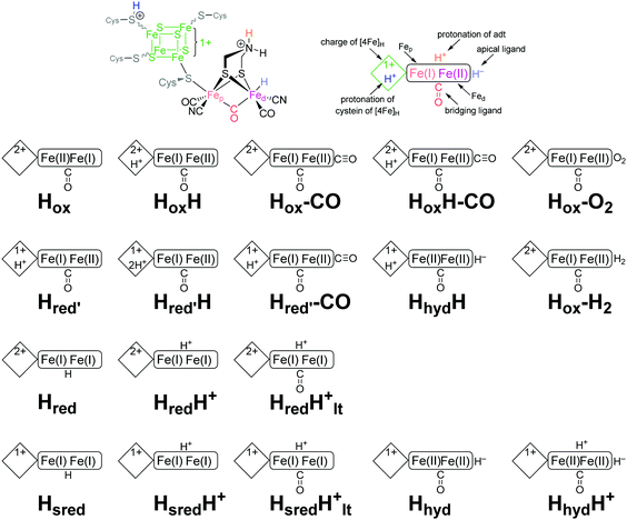
The biosynthesis and assembly of the complete active site of [FeFe]-hydrogenases, called H-cluster, requires the interaction of several maturase proteins HydG, HydE and HydF (see Fig. 1 for an overview). Its whole structure is rather uncommon in biology and consist of two individual iron–sulphur clusters, which are linked by a cysteine sidechain. The first is a [4Fe–4S]-cluster, herein abbreviated with [4Fe]H, which is responsible for electron delivery and serves as electron reservoir by switching between an oxidized and reduced state during the catalytic cycle. The second iron-sulphur cluster is a [2Fe–2S]-cluster. This subsite will be abbreviated [2Fe]H and represents the actual active centre, being the site of catalytic turnover. Depending on the position relative to [4Fe]H, the single iron atoms are termed proximal iron (Fep) and distal iron (Fed), respectively. Fep is octahedrally coordinated by the cysteine's thiolate, a terminal CO and CN− ligand each, two bridging sulphides that form the [2Fe–2S]-cluster and an additional μ-CO ligand, which is in a bridging binding mode between both iron atoms. Fed shows identical ligands but lacks the thiolate of the cysteine therefore showing a square-pyramidal coordination sphere. At the open binding site substrates, e.g. H+ in the Hhyd state and H2 in the Hox–H2 state, as well as inhibiting diatomic gases like CO (Hox-CO) and O2 (Hox–O2) may bind. [2Fe]H is further coordinated by a secondary amine via the bridging sulphides, why this ligand is mostly called adt (azadithiolate, precisely: bis(sulfidomethyl)amine). The whole [2Fe]H cluster, bearing the adt ligand, is therefore casually called ADT. For a complete graphical representation of the H-cluster see Fig. 1, red box.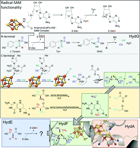 | ||
| Fig. 1 Overview of biological maturase machinery of [FeFe]-hydrogenases. White: N-terminal radical SAM functionality in HydG to initiate the degradation of tyrosine. Grey: reactions performed by HydG yielding a Fe2S2(CO)4(CN)2 core or a FeS(CO)2CN synthon. Yellow: putative PLP dependent conversion of serine by serine dehydratase and serine hydroxymethyltransferase to ammonia and 5,10-methylene tetrahydrofolate. Blue: putative reactivity of HydE. Green: possible substrates of HydF and assembled [2Fe]H-precursor on HydF. Red: completely maturated HydA. PDB entries: HydA: 4XDC, apo-HydF: 3QQ5.2. | ||
In 2010, Mulder and coworkers showed that without HydG, HydE and HydF, the H-cluster contains only the [4Fe]H-cluster (apo-HydA) leading to a change of the quaternary structure of the enzyme. This change results in a positively charged channel leading directly to the active centre, which is used to incorporate [2Fe]H and is closed in the presence of the complete H-cluster.4 HydG is part of the radical S-adenosyl-L-methionine (SAM) enzyme superfamily and accordingly has the usual reactivity:5 SAM chelates an iron atom of a [4Fe–4S]+-cluster via the carboxy and amine function of methionine. The remaining iron atoms are bound to the protein environment by cysteine residues. The Fe–S cluster induces a reductive cleavage of the bound SAM by an inner-sphere electron transfer, resulting in a highly reactive 5′-deoxyadenosyl radical (5′-DA˙) and methionine remains on the now oxidised [4Fe–4S]2+-cluster. 5′-DA˙ abstracts a hydrogen radical of an enzyme specific substrate, forming 5′-DAH and enabling various downstream reactions. In the case of HydG, 5′-DA˙ abstracts one of the hydrogens of a tyrosine amine group.6 The resulting tyrosine radical (Tyr˙) undergoes a homolytic bond cleavage between Cα and Cβ and decomposes into a 4-hydroxybenzyl radical (4-HOB˙) and dehydroglycine (DHG). DHG can subsequently undergo a base-assisted decomposition to form CO as well as CN− and thus serves as a potential source of the biologically unusual ligands for [2Fe]H.7–9
Besides the N-terminal radical SAM functionality, HydG has another Fe–S cluster in C-terminal position: An auxiliary [5Fe–5S]-cluster, which was investigated by EPR spectroscopy and X-ray crystallography.10 The g-values of 9.5, 4.7, 4.1, and 3.7, which are unusual for biological Fe–S clusters, represent an S = 5/2 spin. This unusual observation is caused by a ferromagnetic coupling between a [4Fe–4S]+-cluster (S = 1/2) and an additional high-spin Fe2+ (S = 2). Both are connected by a bridging sulphide of a nonproteinic cysteine (Cys). The additional iron is further coordinated by a histidine (His) residue and two water molecules.11
The CO and CN− ligands obtained by the radical SAM functionality first substitute the aqua ligands of the additional iron resulting in a [4Fe–4S][(Cys)Fe(CO)(CN)(His)]− complex. Subsequently, histidine can also be exchanged by a further CO with the remaining second cyanide binding to the [4Fe–4S]+-cluster and liberating the [(Cys)Fe(CO)2(CN)]− complex which serves as a synthon for [2Fe]H. This cyanide-induced release mechanism explains the 4![[thin space (1/6-em)]](https://www.rsc.org/images/entities/char_2009.gif) :
:![[thin space (1/6-em)]](https://www.rsc.org/images/entities/char_2009.gif) 2 CO
2 CO![[thin space (1/6-em)]](https://www.rsc.org/images/entities/char_2009.gif) :
:![[thin space (1/6-em)]](https://www.rsc.org/images/entities/char_2009.gif) CN ratio of the putative [2Fe]H-precursor. Four tyrosine molecules are required to assemble the putative [2Fe]H-precursor and converted into four CO and four CN−, two of which are cyanides responsible for the release of the synthon [(Cys)Fe(CO)2(CN)]−.6,11
CN ratio of the putative [2Fe]H-precursor. Four tyrosine molecules are required to assemble the putative [2Fe]H-precursor and converted into four CO and four CN−, two of which are cyanides responsible for the release of the synthon [(Cys)Fe(CO)2(CN)]−.6,11
The role of the synthon has recently been further investigated by Britt and Rauchfuss.12 Therein, a biomimetic synthon [FeI2(CO)3CN]− together with cysteine was added to a HydA maturation solution consisting of apo-HydA, HydE and HydF only. In the absence of HydG, this mixture was able to completely activate HydA. Furthermore, with 13C and 15N labels and by using selenocysteine, cysteine was unequivocally shown to be the source of the bridging sulphides within the [2Fe–2S]-cluster but does not provide the NH(CH2)2 bridge.12
Like HydG, HydE is an enzyme of the radical SAM family with two [4Fe–4S]-clusters, as demonstrated by EPR spectroscopy,13 or one [4Fe–4S]- and one [2Fe–2S]-cluster, according to X-ray studies.14 Notably, due to the one-week duration of crystal growth in the X-ray study conducted by Fontecilla-Camps, a degradation of the C-terminal [4Fe–4S]-cluster may have occurred and potentially results in the observed [2Fe–2S]-cluster. However, the [4Fe–4S]-cluster can be removed by mutation without loss of maturase-specific activity and is therefore considered functionally irrelevant for in vivo maturation.14
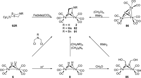
Notably, the role of HydE in the HydA maturase machinery has not yet been finally clarified.7 However, due to its C–S bond formation activity15 it is assumed that the enzyme is involved in the biosynthesis of the adt ligand.13 Serine has recently been identified as the source of the NH(CH2)2 moiety. More specifically, 13C and 15N labels in combination with EPR, HYSCORE- and ENDOR spectroscopy showed that the NH2 and β-CH2 groups are incorporated into the adt bridge.16 It could, however, not be clarified if a further substrate is involved, since possibly only one of the CH2 groups is derived from serine, or whether two serine molecules are needed for the complete construction of the bridge. HydE might therefore use serine to assemble the adt bridge. Here, the serine dehydratase and serine hydroxymethyltransferase were also considered as potentially involved enzymes that convert serine to pyruvate and NH4+ and subsequently with tetrahydrofolate (H4folate) to glycine and 5,10-methylene-H4folate, respectively. Glycine and pyruvate were excluded as possible building blocks of the H-cluster.12,16 However, NH4+ and 5,10-methylene-H4folate, a biological methyl group donor, came into consideration as potential intermediates. With NH4+ and 5,10-methylene-H4folate as reagents, the adt moiety could potentially be introduced into the precursor, [Fe2S2(CO)4(CN)2]2−, comparable to the artificial establishment of the [2Fe]H-cluster by Li and Rauchfuss in 2002 (Fig. 2).17
 | ||
| Fig. 2 Synthesis of Fe2(adt)(CO)6 (2) and Fe2(adt)(CO)4(CN)2 (3) presented by Li and Rauchfuss in 2002. | ||
Furthermore, apo-HydA is activated by HydF, if the latter was expressed together with HydE and HydG.18,19 As EPR and IR spectroscopy as well as XRD and XAS studies have shown, HydF already contains a [2Fe–2S]-cluster alike [2Fe]H. Thus, this maturase enzyme is at the end of the activation chain and passes along the almost completed cluster to HydA.20 HydF serves as a scaffold for the iron–sulphur synthon, which was inferred from co-purification of HydE and HydG with HydF and confirmed in vitro through a combination of surface plasmon resonance and co-purification experiments using recombinant proteins of C. acetobutylicum.18,21–25
2.2 In vitro maturation with artificial H-clusters
In 2013, the groups of Happe, Lubitz and Fontecave showed that chemically synthesised [2Fe–2S]-models with modified bridging dithiols can replace the native [2Fe]H and were successfully incorporated into the apo-enzyme (Fig. 3).26,27 In contrast to the biological process (see above), maturation was achieved utilising a mixture of apo-CrHydA1 and HydF from T. maritima, which was first incubated with the synthetic cluster [Fe2(SCH2XCH2S) (CO)4(CN)2]2− (X = NH (adt), CH2 (pdt), O (odt)). The successful incorporation into HydA1 of Chlamydomonas reinhardtii was demonstrated by the specific CO and CN− bands in the enzyme's IR spectrum. Notably, only the variant with X = NH revealed enzyme-specific hydrogen evolution in the presence of methyl viologen and sodium dithionite at 37 °C.27 With this study, two major uncertainties in [FeFe]-hydrogenases were finally resolved. First, X equals NH in the native [FeFe]-hydrogenase. Previous XRD studies were only capable to narrow down the options to adt, pdt and odt due to the identical electron count.3,28 Thus, early suggestions by Fontecilla and coworkers from 2001 and results obtained from 14N-HYSCORE measurements by the group of Lubitz in 2009 were once and for all proven right.29,30 Second, it was shown that although the [FeFe]-hydrogenases were obtained from different organisms, T. maritima and C. reinhardtii, the maturase enzymes are identical in function. | ||
| Fig. 3 Overview of HydF depended semi-artificial maturation of HydA. PDB entries: Apo-HydA: 4XDD, HydA: 4XDC, apo-HydF: 3QQ5. | ||
Even more remarkable – the very same groups showed that CrHydA1 can be activated without the use of the maturase HydF and is spectroscopically indistinguishable from naturally produced enzymes.26 Herein, the apo-hydrogenase itself is incubated with the synthetic [2Fe]H-precursor (Fig. 4).
 | ||
| Fig. 4 Schematic representation of the artificial maturation of HydA. PDB entries: Apo-HydA: 4XDD, HydA: 4XDC. | ||
This completely artificial process further simplifies the complicated biological maturation process and enables the production and isolation of significantly larger amounts of mature enzymes.9,26 Especially for spectroscopic applications, large quantities of high-purity and fully matured enzymes are required. The development of semi-artificial hydrogenases therefore enabled the deciphering of the catalytic mechanism and mode of action of [FeFe]-hydrogenases and thus the possibility to gain information for a new generation of biomimetic [FeFe]-hydrogenase catalysts.
Using this artificial approach, however, only 14 different non-native diiron sites were tested so far for their ability to mature apo-HydA1 from C. reinhardtii.31 Although mimics of the binuclear subcluster with an altered bridging dithiolate ligand (propanedithiolate, oxadithiolate, thiadithiolate, N-methylazadithiolate (adtMe), dimethyl-azadithiolate) and three variants containing only one CN− ligand were successfully inserted into the apo-enzyme, the activity of those semi-artificial enzymes was below 1% of the native enzyme. In all cases, the insertion process was followed by IR-spectroscopy and the incorporation of the [2Fe]H-mimics is visible by significant line narrowing of the CO/CN− bands compared to measurements of the sole cluster-mimics in solution. This narrowing indicates a loss of vibrational freedom of the ligands and also implies interaction with the protein backbone. This effect was likewise observed for apo-HydA1 maturated with adt-loaded HydF or solely adt.26,27 Upon isolation of the corresponding adt maturated enzyme, multiple signals in the CO region are present indicating a mix of Hox, Hred′, Hred, Hsred and minor amounts of Hhyd. Contrary, enzymes maturated with odt, adtMe and sdt show only Hox and odt is present in Hhyd directly indicating varied H-cluster reactivities of the respective semi-artificial enzymes.
Using the same approach, artificial active sites that were modified at the metal or chalcogenide positions were introduced to apo-CrHydA1 and apo-Cp1.32,33 In 2017, Kertess et al. presented the semi-artificial enzymes CrHydA1 and CpI that were maturated with the selenium derivative of the native cluster, ADSe (4). Remarkably, these enzymes showed up to native-like activity regarding proton reduction, but less stability against O2-degradation and cannibalisation. Thus, significant amounts of Hox-CO were found directly after maturation, which influenced the activity in F-cluster bearing CpI (see Section 3.9) more than in HydA1.32
Later in 2018, Sommer et al. presented a hybrid-enzyme with a [RuRu]-analogue of ADT, which was investigated due to the interesting reactivity of the noble metal towards hydrogen. Both versions, [Ru2(adt)(CO)4(CN)2]2− (5) and the protonated species bearing a bridging hydride (5-μH) were found to be in the same state, namely Hhyd, after incorporation into the protein environment.33 Especially the isomerization of the hydride shows the remarkable influence of the protein backbone on the structure of the diiron subsite, stabilizing the thermodynamically less stable terminal hydride (Fig. 5).
 | ||
| Fig. 5 Synthetic subsite models with chalcogen or metal exchange that has been implemented into apo-enzymes. | ||
2.3 In vivo maturation with artificial H-clusters
A more recent approach regarding [FeFe]-hydrogenase maturation and, especially, its modification and in vivo investigation was presented by Berggren and coworkers in 2017.34 The researches transferred the results of the in vitro maturation experiments (Section 2.2) to an in vivo system consisting of apo-CrHydA1 that was heterologously overexpressed in E. coli (Fig. 6). In opposition to former experiments, the hydrogenase was not extracted from its host but left inside the living cells. Since E. coli lacks the maturation machinery HydEFG, the hydrogenases inside the cells remain inactive. However, in analogy to the in vitro experiments, addition of 1 mg 3 to the cell cultures (O.D. = 0.2 ± 0.02) resulted in a 35- to 40-fold increase over the background H2 evolution activity, indicating successful activation of the apo-enzymes.34 The described results represent the first intracellular activation of an apo-enzyme not including improved cellular import functions and opens up the field for in vivo spectroscopic investigation of [FeFe]-hydrogenases by e.g. EPR and FTIR.35,36 Even more remarkable is the follow-up study as a joint research of the groups of Berggren and Lindblad, who targeted the modification of the photoautotrophic cyanobacterium Synechocystis PCC 6803. This bacterium harbours a bidirectional [NiFe]-hydrogenase for energy household. However, for biotechnological energy applications, high rates of hydrogen evolution are wanted. Here, the [NiFe]-hydrogenase is by far surpassed by [FeFe]-hydrogenases. Therefore, the hydrogenase CrHydA1 was expressed in a hydrogenase deficient mutant of Synechocystis PCC 6803 (Δhox) as well as in the wild type (WT) organism, containing the native [NiFe]- and the additional [FeFe]-hydrogenase. Upon addition of compound 3, Synechocystis Δhox CrHydA1 and WT-CrHydA1 showed a hydrogen evolution activity of approx. 62 and 48 (nmol O.D.−1 mL−1), respectively, whereas the organisms without 3 showed almost zero activity (Synechocystis Δhox CrHydA1) and 17 (nmol O.D.−1 mL−1) for WT-CrHydA1. This nice work of bio-engineering underlines that the hydrogen production rates of Synechocystis can be increased by enzyme optimization and opens a new field of artificially improved enzymes for biotechnological hydrogen production.37III Reactivity of the H-cluster within the enzyme
The hydrogenase activity of green algae was investigated already 80 years ago by Gaffron and coworkers, who found S. obliquus to metabolize H2 upon reduction of CO2 in photosynthesis.38,39 Among all algae, C. reinhardtii with an in vitro activity of 200 nmol H2 (μg Cr a h)−1 bears by far the most investigated [FeFe]-hydrogenase HydA1.40–42 This hydrogenase contains solely one Fe–S cluster assembly, called H-cluster, and no additional accessory Fe–S cluster for e.g. electron transport as in hydrogenases from D. desulfuricans and C. pasteurianum.43–47 Its simplicity thus makes HydA1 most convenient for researching the molecular proceedings of H2 turnover during catalysis.The H-cluster consists of a [4Fe–4S]- and a [2Fe–2S]-cluster, which are linked and electronically coupled via a cysteinyl thiolate.1,3,28,48,49 The cubic iron cluster, embedded into the protein by three additional cysteine residues, is part of the electron chain and, more importantly, is the midpoint of a proton coupled electron transfer (PCET) at the beginning of the catalytic cycle.50–52 The diiron subsite conducts the catalytic proton reduction and is the focal point on mimics of the [FeFe]-hydrogenases as we will discuss in Section IV. The diiron site consists of a proximal iron that has an octahedral ligand environment and a distal iron in a square pyramidal coordination with an open binding site for substrates (H+/H2) and exogenous ligands such as CO and O2 (Fig. 8). This geometry of the H-cluster in its Hox state is called “rotated state”, which refers to the rotation of the distal iron relative to the C2v symmetric Fe2S2(CO)6 core. This special geometry opens a vacant binding site for catalytic turnover and is a unique feature of this active site and was a dominant motif for the design of H-cluster mimics for hydrogen evolution (Fig. 8, Section 5.1).53
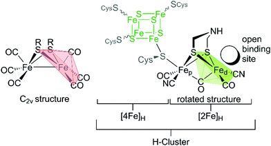 | ||
| Fig. 8 H-cluster of [FeFe]-hydrogenases with indicated rotated motif of the distal iron atom (green) vs. the Fe2S2(CO)6 core in C2v symmetry (red). | ||
We now want to review the reactivity of the H-cluster within the native protein environment. This will include the natural [FeFe]-hydrogenase HydA1 from C. reinhardtii, but also hydrogenases from other organisms like C. pasteurianum, D. desulfuricans, the sensory hydrogenase HydS from T. maritima as well as the half-synthetically obtained hydrogenases. Besides different organisms, we will especially highlight the man-made alterations within the [FeFe]-hydrogenases, ranging from different [2Fe–2S]-cluster to mutants, for spectroscopic or stability reasons.
3.1 ADT-bridged [FeFe]-hydrogenase from C. reinhardtii
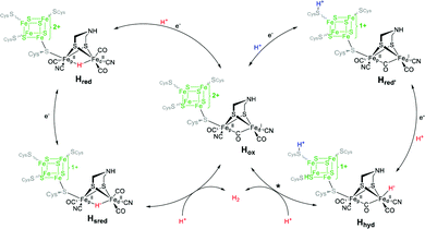
CrHydA1(ADT) is the active enzyme version of the [FeFe]-hydrogenase from C. reinhardtii (therefore denoted Cr), in which all intermediates of the catalytic cycle are generally available. Note that more than ten different redox states of the enzyme are nowadays accessible, in which protonation and reduction may occur at different moieties of the H-cluster during catalysis (Fig. 7). As shown in the experiments on CrHydA1(ADT) with NaDT (sodium dithionite) or H2, selective enrichment of the intermediate states is challenging, often resulting in blurred spectroscopic results, which impede the exact determination of the nature of each redox state. Using difference spectra is one potential option to handle this problem in IR-spectroscopy. However, for this approach specific equipment is required, which is not accessible in all laboratories.Therefore, hybrid enzymes, having a bridgehead moiety that differs from adt, as well as mutants providing selectively exchanged amino acids within the peptide backbone are promising options to influence the activity of the enzyme and therefore the accessibility of the H-clusters’ redox states. In the next section, we therefore discuss those modifications and highlight the differences towards CrHydA1(ADT) and their opportunities for spectroscopic applications.
3.2 Reactivity of CrHydA1(ADT) towards oxidising conditions
H ox is the oxidised resting state of the H-cluster and therefore starting point of most conducted experiments. This state can be enriched by treating the enzyme with mildly oxidising reagents such as thionine buffered at pH 8 (E0 = 60 mV vs. SHE at pH 7). However, due to cannibalisation under these conditions, a mixture of Hox and Hox-CO (Section 3.3) is achieved.54,55 The cannibalisation process is based on the degradation of a fraction of the enzyme sample under influence of e.g. light or oxygen.54,56,57 Thereby, the released CO binds to the intact H-cluster from a non-degraded enzyme and blocks the active site while forming Hox-CO.58 Therefore, Hox can be better enriched by auto-oxidation under inert conditions (e.g. N2), which results in a near quantitative enrichment of this state.55,59The electronic structure of the enzymes resting state Hox from CrHydA1 was investigated by different techniques. EPR spectroscopy (Table 1) on native CrHydA1 which was not treated with any oxidant or reductant (termed “as-isolated”) shows a rhombic 2.1 signal (g = 2.100, 2.037, 1.996) and an axial 2.05 signal (g = 2.052, 2.007).55,57,60 The former signal resembles the EPR signal of Hox that is known from measurements on hydrogenases from D. desulfuricans (DdH).49,54 The axial signal accounts for the presence of Hox-CO in the as-isolated samples, likewise known from DdH,56,62,63 and is absent in auto-oxidised samples.55 ENDOR-spectroscopy (ENDOR = electron nuclear double resonance) on native DdH in combination with Mössbauer spectroscopy on hydrogenase II from C. pasteurianum (CpII)48 concluded that Hox is best described as a mixed-valent paramagnetic [4Fe–4S]2+–[Fep1+Fed2+] complex with the net spin density on the proximal iron atom.29,49 Due to close similarity of EPR signals from DdH and CrHydA1, Hox was assigned to a [4Fe–4S]2+–[Fep1+Fed2+] state.55,60 The development of artificial H-cluster maturation (Section 2.2) enabled access to higher amounts of pure CrHydA1, which is especially advantageous for spectroscopic applications and crystallisation experiments. Likewise, the site-selective labelling with 57Fe, i.e. labelling either [4Fe]H or [2Fe]H, became possible with the in vitro approach for the first time. Based on this artificially maturated CrHydA1, recent studies using site-selective X-ray absorption and emission spectroscopy (XAE-spectroscopy) came to opposing results as compared to ENDOR spectroscopy and suggested a [4Fe–4S]2+–[Fep2+Fed1+] cluster with the net spin density at the distal instead of the proximal iron.64 As a result, XAE- and EPR spectroscopy remain inconclusive regarding the oxidation states of iron within the diiron site. However, it cannot be concluded, if this discrepancy is a result of technical insufficiencies or is even related to the different enzymes used (DdH and CpI/II exhibit additional Fe-clusters besides the H-cluster that might account for the inconclusive results).
| state | CrHydA1 | DdH | CpI | CpII | TmHydS | |||||
|---|---|---|---|---|---|---|---|---|---|---|
| g-Value | Ref. | g-Value | Ref. | g-Value | Ref. | g-Value | Ref. | g-Value | Ref. | |
| a Not reported. | ||||||||||
| H ox | 2.10, 2.037, 1.996 | 60 | 2.100, 2.040, 1,999 | 49 | 2.10, 2.04, 2.00 | 49 | 2.078, 2.027, 1.999 | 49 | 2.113, 2.045, 2.001 | 61 |
| H ox -CO | 2.052, 2.007 | 60 | 2.065, 2.007, 2.001 | 49 | 2.07, 2.01, 2.01 | 49 | 2.032, 2.017, 1.997 | 49 | 2.045, 2.918, 2.007 | 61 |
| H red | Silent | Silent | Silent | Silent | Silent | |||||
| H sred | 2.076, 1.943, 1.868 | 60 | ||||||||
| H red′ | Silent | Silent | Silent | Silent | Silent | |||||
| H hyd | Broad signal centred between 2.3 and 2.07 | 55 | ||||||||
Since the ligand environment of Hox is build up from three CO and two CN− ligands,3,28 IR spectroscopy is yet another strong method for its characterisation and the exact position of ligand vibrations is very sensitive to the electron density and cluster geometry.26,27,29,65 Typically, vibrations of terminally bound carbonyl ligands are found between 2020 cm−1 and 1940 cm−1, whereas their bridging relatives show less intense signals between 1850 cm−1 and 1750 cm−1. In addition, terminally bound cyanide ligands characteristically reveal bands between 2120 cm−1 and 2020 cm−1.
For example, Hox has a very characteristic IR-spectrum revealing two cyanide bands at 2088 cm−1 and 2072 cm−1, two terminal CO bands at 1964 cm−1 and 1940 cm−1 and the bridging carbonyl at 1800 cm−1.55,56,60,64,66 In 2016, Stripp and coworkers presented a method to selectively label the H-cluster with 13CO by controlling the hydration of a protein film and exposing it to 13CO gas under light irradiation.56,59 This enabled the CO band assignment to the specific ligands. Furthermore, DFT calculations on all isotope labelled H-cluster variants further suggested largely uncoupled CO vibrations of the Fe–Fe bridging carbonyl (μ-CO, band α, 1800 cm−1) as well as the terminal ligands at the distal (dCO, band β, 1940 cm−1) and proximal (pCO, band γ, 1964 cm−1) iron atoms.59
While the experimentally supported DFT-model and the observed structure from protein crystallography are well in line,3,28 a second structure with an apical CN− was likewise found to be a suitable state (Fig. 9, Hoxb).59,67 However, while Hoxa was obtained based on XRD measurements at low temperature (approx. 80 K),3,28 the structure Hoxb stems from a DFT calculation/IR spectra analysis conducted at room temperature. Thus, Hoxb might be a higher energy state of Hox. While the reason for this discrepancy is not known, H-cluster flexibility might be an important feature in order to stabilise redox states with additional ligands at the distal iron (i.e.Hox-CO and Hhyd, Section 3.5).67,68 The exact assignment of the spectroscopic bands furthermore enabled insight into the electronic structure as well and allowed to resolve the discrepancy from EPR and XAE-spectroscopy, which remained inconclusive regarding the oxidation states of the diiron site. According to IR-spectroscopy, the [Fep2+Fed1+] configuration should be favoured, since the CO band of the proximal ligand is shifted to higher wavenumbers compared to the signal of dCO thus supporting the EPR analysis and hints towards a decreased electron density at the proximal iron centre.
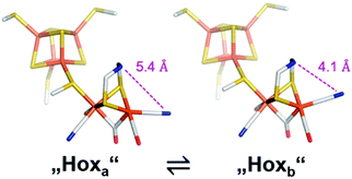 | ||
| Fig. 9 Conceivable isomers of Hox. Out of two structural isomers of the active-ready oxidised state, “Hoxa” represents the crystallized geometry while “Hoxb” is characterized by a partly rotated, distal CN− ligand. Reprinted from ref. 67 with permission from the American Chemical Society, Copyright 2019. | ||
3.3 Reactivity of CrHydA1(ADT) towards CO
As mentioned in the previous section, cannibalisation by treatment with thionine leads to Hox-CO besides Hox. Intentionally, this state can be enriched by treatment of Hox with exogenous CO gas.62,66 Hammerström, Lubitz and coworkers reported that the additional carbonyl within Hox-CO can be released by a laser pulse with an energy of 355 nm. Using time-resolved FTIR spectroscopy, a half-life of t1/2 = 13 ± 5 ms of the dissociated CO could be determined, before rebinding occurs.69 The molecular structure of the H-cluster in its Hox-CO state was likewise investigated by X-ray crystallography of the CO inhibited hydrogenase I from C. pasteurianum (CpI). As expected, electron density that arises from a diatomic ligand was found in apical position of the distal iron, which is accompanied by an elongation of the Fe–Fe distance from 2.56 Å in Hox to 2.71 Å in Hox-CO.49,62 The IR spectrum of Hox-CO likewise accounts for the extra CO by an additional band in the region of terminal carbonyl ligands (Table 2, d2CO, band δ, 2012 cm−1), while bands β and γ shift to 1962 cm−1 and 1968 cm−1, respectively.56,58–60,64,70 These band positions reveal a vibrational coupling of the carbonyl ligands, as already reported by Albracht and coworkers.66 A pronounced vibrational coupling between all terminal CO ligands was later uncovered by DFT calculations.59 The nature of the diatomic apical ligand, however, cannot be determined by XRD analyses due to the close geometric and electronic resemblance of CO and CN−. While an apical CO is favoured by most research groups, IR spectroscopy accompanied by DFT analysis suggested a rotation of the distal iron, enabled by the cluster flexibility (see above) and resulting in an apical CN− instead of an apical CO.59,64 The electronic structure of Hox-CO is thus still under rigorous debate. The [4Fe–4S]-cluster, consisting of two antiferromagnetically coupled hs-FeIIFeIII (S = 9/2) subclusters, is overall in a +2 (S = 0) state, similar to Hox. Interestingly, although for singlet spin states such as observed for [4Fe]H no hyperfine coupling (hfc) should be observed, a pronounced spin exchange between [4Fe]H and [2Fe]H results in a strong hfc that differentiates Hox-CO from Hox, where no hfc is observed. Mössbauer,48,71,72 EPR,49,71 and X-ray spectroscopy64,73 as well as computational studies,64,73 agree well with this finding and suggest a S ≠ 0 state for [2Fe]H. However, the electronic structure has to be different than in Hox due to the observed hfc of [4Fe]H. Here, early Mössbauer studies by Popescu and Münck favoured a paramagnetic FeIIFeIII state, whereas a FeIFeII could not be excluded.48 The latter description was, however, favoured by Lubitz and coworkers performing ENDOR measurements on 57Fe enriched DdH and suggesting an electronic configuration with a paramagnetic FeI in proximal position.49 Although most of the spin density is at Fed, a substantial spin delocalisation over the whole cluster was reported as well, which is induced by the binding of the additional CO.63 Due to the spin coupling between [4Fe]H and [2Fe]H and the resulting spin distribution, the EPR spectrum of Hox-CO differs from Hox although the redox state seems to be the same. This coupling results in an axial 2.07 signal (g = 2.065, 2.007, 2.001).49,54,63 The strong spin distribution was also detected by XAE spectroscopy on HydA1 from C. reinhardtii that assigned Hox-CO as [4Fe–4S]2+–[Fe1.5+Fe1.5+]3−, corroborated by DFT calculations.64| State | ν(CN−)/cm−1 | ν(CO)/cm−1 | Ref. |
|---|---|---|---|
| H ox | 2088, 2070 | 1964, 1940, 1802 | 75 |
| H ox H | 2092, 2074 | 1970, 1946, 1812 | 75 |
| H ox -CO | 2091, 2081 | 2012, 1968, 1962, 1808 | 51 |
| H ox H-CO | 2094, 2086 | 2006, 1972, 1966, 1816 | 51 |
| H red′ | 2084, 2066 | 1962, 1933, 1792 | 51 |
| H red′ H | 2086, 2068 | 1966, 1938, 1800 | 51 |
| H red′ -CO | 2086, 2076 | 2002, 1967, 1951, 1793 | 70 |
| H red | 2070, 2033 | 1961, 1915, 1891 | 75 |
| H red H + | 2071, 2032 | 1968, 1917, 1891 | 76 |
| H red H + lt | 2079, 2041 | 1916, 1894, 1810 | 77 |
| H sred | 2068, 2026 | 1953, 1918, 1882 | 75 |
| H sred H + | 2067, 2027 | 1953, 1917, 1881 | 76 |
| H sred H + lt | 2070, 2026 | 1919, 1882, 1803 | 77 |
| H hyd | 2082, 2068 | 1978, 1960, 1860 | 75 |
3.4 Reactivity of CrHydA1(ADT) towards reducing reagents – A: sodium dithionite (NaDT)
Relative to Hox, multiple single and double reduced H-cluster redox states are known. These can be accessed by treatment of the as isolated or Hox enriched species with chemical reducing agents. At first, we want to consider treatment of Hox with sodium dithionite (NaDT), which has a potential of −660 mV vs. SHE at pH 7 and is one of the most frequently used reducing agents in the hydrogenase community. In these assays, NaDT compensates the lack of a physiological electron donor and enables the formation of hydrogen.Treatment of as-isolated CrHydA1 with a 17-fold concentration of NaDT at pH 8, followed by direct freeze quenching of the samples in liquid N2 results in the loss of Hox specific IR bands in favour of multiple signals (Fig. 10, entry A).60 Those signals were originally attributed to the single reduced [4Fe–4S]2+–[FeIFeI] complex and a double reduced species that is called Hsred (= “super reduced”). However, due to the presence of a second bridging CO signal, the existence of Hox in this assembly cannot be excluded. Especially the corresponding EPR spectrum (Q-band, FID detected) points to the presence of unreacted Hox, showing the characteristic rhombic 2.1 signal. In addition, a broad signal with lower g values (g = 2.076, 1.943, 1.868) is present in the resulting spectrum. This signal resembles a reduced [4Fe–4S]-cluster, which has to stem from a double reduced H-cluster, since [4Fe–4S]2+–[FeIFeI] (Hred) and [4Fe–4S]+–[FeIIFeI] (Hred′) are EPR silent.74 Therefore, the double reduced Hsred has to be denoted as [4Fe–4S]+–[FeIFeI] rather than a [4Fe–4S]2+–[FeIFe0].60
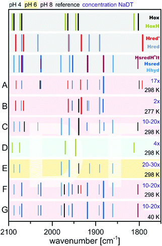 | ||
| Fig. 10 Schematic representation of IR band positions of NaDT reduced CrHydA1 (colored background) in comparison with currently known states (grey background). The concentration factor (x) of NaDT is related to the protein concentration. IR signatures of known states are taken from Table 3. References for entries A–G: A,60 B and C,55 D,51 E,78 F and G.77 | ||
Contrary, King and coworkers observed different results in their IR and EPR spectroscopic investigation under reducing conditions. While a 2-fold NaDT concentration and incubation at 4 °C overnight led to the same states as observed by Lubitz and coworkers (Fig. 10, entry B), a 10- to 20-fold NaDT concentration and incubation at room temperature for one minute led to decreasing bands at 1933 cm−1, 1883 cm−1 and emerging bands at 1979 cm−1, 1803 cm−1 as well as 1861 cm−1 (Fig. 10, entry C), which were not observed in the spectra of Lubitz and coworkers.55
Subsequently, EPR spectroscopy was used to disentangle the mixture of states found by IR spectroscopy. Samples reduced with 2 equiv. NaDT at 4 °C afford the Hred, Hred′ and Hsred states according to IR spectroscopy. The corresponding EPR spectrum shows a broad signal between g = 2.3 and 2.07. Since Hsred should be the only EPR active state, this broad signal must occur from this double reduced species. In addition, the temperature and power properties of the broad EPR signal was found to fit best to a reduced [4Fe–4S]-cluster consistent with the findings of Lubitz and coworkers for Hsred. Contrary, utilizing 10- to 20-fold concentrated NaDT reduced samples (Fig. 10, entry C), signals of a hitherto unknown state were observed. The EPR spectrum shows a 90% contribution of a broad rhombic signal of g = 2.077, 1.935, 1.880 and minor contributions from rhombic 2.1 signal (Hox). Again, a reduced [4Fe–4S]-cluster was suggested to be the origin of this signal. Notably, according to a post hoc IR analysis, the dominant species in this sample is Hhyd, which was postulated as an intermediate species within the native reaction cycle, e.g. a [4Fe–4S]+–[FeIFeI]–H+ or a [4Fe–4S]+–[FeIIFeII]–H−.55 Therefore, Hhyd seems to accumulate under strongly reducing conditions, whereas Hred′ cannot be found. Both possible Hhyd species are uncharacterized intermediates at the beginning of the H2 splitting cycle or at the very end of the H+ reduction cycle, respectively.
The experiments described so far were all performed at pH 8. However, the interconversion of protons and molecular hydrogen is according to the law of mass action always dependent on the pH. Therefore, accumulation of intermediate states was thought to be easier when increasing or decreasing the proton concentration and thus, shifting the equilibrium to a specific H-cluster state. Following this approach, treatment of CrHydA1 in its Hox state with a 4-fold concentration of NaDT at pH 4 resulted in an unknown species with upshifted CO/CN− frequencies by 4 to 6 cm−1vs.Hox instead of accumulation of a reduced species that would have been accompanied with downshifted CO and CN− frequencies (Fig. 10, entry D). The formation of this species was shown to be reversible when switching back to pH 8.51 This new species was denoted as HoxH, indicating a tentative protonation event at the H-cluster but an overall similar redox state as Hox. Interestingly, no change in the IR pattern could be observed in the absence of NaDT, which points to the necessity of reducing (“turn-over”) conditions. Although the transition from Hox to HoxH is not a PCET, since both, [4Fe]H and [2Fe]H remain in the same oxidation state according to IR-supported DFT calculations, the pH and NaDT dependent formation of HoxH suggests involvement of a PCET in its formation. Potentially, HoxH is the endpoint of the catalytic cycle, which is PCET based.51 Deprotonation of HoxH is thus the last step of the H2 formation cycle and results in the regain of Hox. DFT calculations along with IR spectroscopy were performed to investigate the presence of an additional proton within HoxH. The band correlation agreed best with a protonation at the cysteine S9 at [4Fe]H, whereas protonation at one of the four bridging sulphides of the [4Fe–4S]-cluster led to strong cluster distortions and protonation at the first ligand sphere or at [2Fe]H led to substantial stronger shifts of the CO and CN− frequencies.51 Experiments at pH 8 show that Hhyd can be found alongside with Hox, Hred and Hsred under strongly reducing conditions.55 Drastically increasing the concentration of NaDT (20- to 30-fold) while simultaneously increasing the proton concentration to pH 6 yields almost pure Hhyd with minor amounts of Hred and Hox (Fig. 10, entry E).78 This sample was further analysed by NRVS (nuclear resonance vibrational spectroscopy), providing vibrational information only for Mössbauer active elements, e.g. iron. The resulting spectrum shows two high energy bands at 675 cm−1 and 744 cm−1, characteristic for a terminal bound hydride. Upon changing the medium from H2O to D2O both signals are replaced by a new signal at lower energy (629 cm−1), in line with H/D exchange of this terminal hydride.78 The NRVS spectra were taken as basis for sophisticated DFT calculations to determine a possible structure for Hhyd. The best overall agreement between calculated and measured spectra was obtained for a [4Fe–4S]+–[FeIIFeII]–H− species, in which the amine is neutral and with the amine proton pointing towards the hydride forming an internal hydrogen bond.78 Another hydrogen bond is formed between the lone pair of the amine and the adjacent thiol group of Cys169, which is believed to be the last amino acid in a proton channel towards the H-cluster.79 Besides the proposed Hhyd structure, arrangements with a protonated bridge structure (R2NH2+) were tested as well with very low agreement between the calculated and observed spectra. However, such a state was not completely ruled out but considered as potential intermediate species between Hhyd and the H2 releasing/uptaking state.78
Besides the influence of the pH value, the relevance of the temperature at which the experiments are performed was highlighted as well. Incubation with an approx. 10- to 20-fold concentration of NaDT (a 20 mM solution NaDT was used for reduction of CrHydA1; however the concentration of the enzyme is not stated) gave a mixture of Hhyd, Hsred, Hred and in minor amounts Hred′ and Hox both, at 280 K and 40 K.77 However, at 40 K the intensity of the signal at 1803 cm−1 increases strongly. This signal was assigned to a double reduced H-cluster state, which bears a bridging CO that is not detected in Hsred60,80 (bridging hydride) or HsredH+![[thin space (1/6-em)]](https://www.rsc.org/images/entities/char_2009.gif) 76 (semi-bridging CO and adt-H+). This assignment is based on the concomitant increase of Hsred signals at 40 K. We therefore denote this species as HsredH+-lt that is claimed as [4Fe–4S]+–[FeIFeI] with protonation at the amine, to distinguish between low- and high-temperature states. The low-temperature IR measurements were further strengthened by NRVS measurements and DFT calculations in which both a μ-CO and a μ-H were considered. Models including μ-H produced a high-energy signal around 740 cm−1 which was observed in synthetic μ-H models and experiments of [NiFe]-hydrogenases as well,81 but not found in experiments on [FeFe]-hydrogenases.77 A μ-H ligand under these conditions was therefore rendered unlikely, while in conclusion a μ-CO ligand was favoured. However, the unchanged frequency of μ-CO compared to Hox is not explained and remains inconclusive from our point of view. The reduction of [4Fe]H within the Hox ↔ Hred′ transition results in a downshift of the μ-CO frequency of 8 cm−1.51,74,76,82 The same IR band in HsredH+-lt does not shift compared to Hox, although it should result in a larger shift of the μ-CO frequency vs.Hox due to the reduction of [2Fe]H. However, it must be considered that the measurements at 40 K are under non-physiological conditions, which shows that the temperature at which [FeFe]-hydrogenases are investigated, indeed can influence the outcome of the experiment by means of trapping the H-cluster in different states compared to measurements at room temperature.
76 (semi-bridging CO and adt-H+). This assignment is based on the concomitant increase of Hsred signals at 40 K. We therefore denote this species as HsredH+-lt that is claimed as [4Fe–4S]+–[FeIFeI] with protonation at the amine, to distinguish between low- and high-temperature states. The low-temperature IR measurements were further strengthened by NRVS measurements and DFT calculations in which both a μ-CO and a μ-H were considered. Models including μ-H produced a high-energy signal around 740 cm−1 which was observed in synthetic μ-H models and experiments of [NiFe]-hydrogenases as well,81 but not found in experiments on [FeFe]-hydrogenases.77 A μ-H ligand under these conditions was therefore rendered unlikely, while in conclusion a μ-CO ligand was favoured. However, the unchanged frequency of μ-CO compared to Hox is not explained and remains inconclusive from our point of view. The reduction of [4Fe]H within the Hox ↔ Hred′ transition results in a downshift of the μ-CO frequency of 8 cm−1.51,74,76,82 The same IR band in HsredH+-lt does not shift compared to Hox, although it should result in a larger shift of the μ-CO frequency vs.Hox due to the reduction of [2Fe]H. However, it must be considered that the measurements at 40 K are under non-physiological conditions, which shows that the temperature at which [FeFe]-hydrogenases are investigated, indeed can influence the outcome of the experiment by means of trapping the H-cluster in different states compared to measurements at room temperature.
3.5 Reactivity of CrHydA1(ADT) towards reducing reagents – B: hydrogen (H2)
Notably, comparable reactivity alterations were observed upon exchange of the reducing agent – e.g. substituting NaDT as reductant with H2. Under physiological conditions, the former results in formation of H2 and oxidation of an external electron donor, while the latter variant results in the final reduction of an electron acceptor and formation of protons. This interplay is of utmost importance for balancing energy levels of hydrogenases in living organisms. As an additional benefit from changing to H2 as reducing agent is the determination of the reversibility of catalytic states. If the respective states are accessible from both approaches, H2 formation and oxidation, theses states are most likely part of a catalytic cycle, while states that are accessible only by one method might lead to biologically less-relevant resting states or artificial, naturally non-appearing states.According to IR spectroscopy, flushing of CrHydA1 with 100% H2 for 15 minutes at 4–24 °C and pH 8 yields Hsred with minor amounts of Hred, Hred′ and eventually very small amounts of Hox (Fig. 11, entries A, B).55,60 All reduced states can also be accessed by reduction with NaDT, rendering these three states potential intermediate candidates for a H2 formation cycle. It seems that, depending on the applied temperature, either Hsred (higher temperatures, entry B) or Hred (lower temperatures, entry A) are favoured. However, due to the opposed measurement temperatures, i.e. 100 K for samples flushed with H2 at 24 °C and 294 K for samples prepared at 4 °C, a qualitative analysis of this trend cannot be deduced.
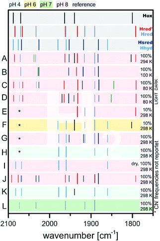 | ||
| Fig. 11 Schematic representation of IR band positions of H2 reduced CrHydA1 (coloured background) in comparison with currently known states (grey background). IR signatures of known states are taken from Table 2. References for entries: A,55 B,60 C and D,82 E and F,51 G to I,75 J and K,67 L.72 | ||
It is worth mentioning that under 100% H2, all single and double reduced species are observed. Here, lower amounts of reducing agents, i.e. 10% H2 in N2, result in formation of the single reduced species Hred and Hred′ at the expanse of Hox, while Hsred seems to be absent in those samples according to IR spectroscopy (Fig. 11, entries E, F).51
The absence of Hsred in 10% H2 treated samples is an advantage compared to all NaDT reduced species. Herein, persistent contributions from Hsred crowding the IR spectrum were reported, impeding an evaluation of the resulting spectra. Moving from alkaline pH 8 to more acidic pH 6 (Fig. 11, entries E, F)51 at constant H2 concentrations (10%) favoured the formation of Hred, Hox and minor amounts of Hhyd over Hred′ and Hsred and vice versa.51,72 This behaviour was also observed in a redox titration experiment of CrHydA1(ADT) at different pH values (Section 3.6) and was accounted to a “non-classical” intra H-cluster PCET, i.e. as transition from a [4Fe–4S]+–[FeIFeII] (Hred′) to a [4Fe–4S]2+–[FeIFeI] (Hred) cluster.76 Simultaneously to the decrease of the Hred′ marker band at 1933 cm−1, switching from alkaline to acidic pH decreases the signal of the bridging carbonyl at 1972 cm−1 with the same rate and indicates that Hred′ most likely bears a μ-CO, ligand as opposed to Hred.51,76 Therefore, the PCET from Hred′ to Hred was suggested to be coupled to a ligand rearrangement, which has been considered challenging to merge with the large hydrogen turnover rates of [FeFe]-hydrogenases.51,68,83
The previously described conditions used by Stripp and coworkers gave small amounts of Hhyd upon increasing the proton concentration to pH 6. This work was later revisited by Winkler and coworkers: upon changing the pH from 8 to 4 while purging a sample of HydA1 with 100% H2 led to IR bands at 1978 cm−1, 1960 cm−1, 1891 cm−1 and 1860 cm−1.75 While the signal at 1891 cm−1 stems most likely from Hred, the remaining bands were assigned to Hhyd (Fig. 11, entries G, H). This example shows, how Le Chatelier's principle can be applied to enrich specific catalytic states of [FeFe]-hydrogenases within the complex biological environment.67,75 The simultaneous increase of starting material (H2) and proton concentration (i.e. pH < 6) prevents deprotonation of the H-cluster and traps Hhyd. The deprotonation step is therefore presumably involved in the Hhyd → Hred′ or Hhyd → HsredH+ conversion.
However, there is an ongoing discussion about the importance and the assignment of specific states leading to sometimes severe alterations of suggested mechanistic schemes. Nevertheless, and independent of the preferred reaction scheme, Hhyd was unequivocally suggested to be a key intermediate in the hydrogen cycle.
Identical results were observed using a dry H2 stream (Fig. 11, entry I) explained by the loss of proton acceptors, i.e. the aqueous medium, and therefore accumulation of H+ within the enzyme. It was suggested that the lost proton acceptors are equivalent to an increase of the proton concentration by lowering the pH, which yields Hhyd as well.75 A similar effect was observed upon impairing the proton transfer path by e.g. disrupting it via mutagenesis or exchanging the bridgehead of [2Fe]H (Sections 3.7 and 3.8).64,75,78,84,85
3.6 FTIR spectroelectrochemistry of CrHydA1(ADT)
As shown in the previous section, treatment of CrHydA1(ADT) with reducing agents generally results in a mix of various redox states depending on the redox potential of the used reductants (Fig. 10 and 11). Importantly, preparing specific desired redox states can be controlled by using electrochemical approaches. In addition, since the redox potentials can be selectively adjusted, each redox state of the H-cluster can be enriched to almost complete purity. Especially in combination with IR or EPR spectroscopy (spectroelectrochemistry, SEC), electrochemical measurements become a powerful tool to investigate e.g. proton coupled electron transfers or the redox states in general.52,58,70,74,76,80,86At −300 mV vs. NHE or more anodic potentials and broadly independent of pH, Hox is populated according to SEC-IR experiments (Fig. 12, entries A, E, L).74,76,80 First experiments on CrHydA1 at open circuit potential (OCP) and pH 8 (Fig. 12, entry J) afforded Hox-CO from the cannibalisation process besides Hox. The amount of Hox-CO increased upon switching to −260 mV indicating additional enzyme damage, while the concentration of Hox decreases. Interestingly, going to even more cathodic potentials (−430 mV) led to a complete loss of Hox-CO, while Hred′ was enriched to almost purity with only minor impurities (Fig. 12, entry N).58 This behaviour shows that inactive Hox-CO can be reactivated by applying a sufficient reducing potential as long as no exogenous CO is added to the sample. Applying a potential of −300 mV at pH 8 in the presence of exogenous CO yields Hox-CO instead of Hox (Fig. 12, entries Q, T) as well as Hred′-CO if more reducing conditions are applied (Fig. 12, entries R, S, U).70,74 Nevertheless, Hox-CO can be found at potentials as low as −600 mV (Fig. 12, entry U). The midpoint potential of the Hox-CO → Hred′-CO conversion was determined to be −360 ± 10 mV at pH 5 (Fig. 12, entries V, W) and −530 ± 30 mV at pH 8 (Fig. 12, entries T, U),70 which is in line with earlier experiments determining a midpoint potential.74 A similar pH dependent behaviour was likewise found for the Hox → Hred′ couple in CrHydA1(PDT) (Section 3.7). A shift of 60 mV per pH unit indicates a proton dependent formation of Hred′-CO according to the Nernst equation (PCET).70 This protonation event was also assigned to the Hox → HoxH transition. It was claimed that the proton herein is located at the [4Fe]H stabilizing cysteine S9.51 This protonation decreases the electron density of [4Fe]H and facilitates the reduction of the [4Fe–4S]-cluster, which is in line with the more anodic midpoint potential at pH 5 (protonated Cys S9) vs. pH 8 (unprotonated Cys S9). Supposedly, the electronic structure of Hred′-CO is therefore best described as [4Fe–4S]+–[FeIFeII] comparable to the electronic state of Hred′.70 The molecular structure of Hred′-CO is comparable to Hox-CO with an apical vacancy, blocked by CO.70 According to a DFT-FTIR correlation, rotational freedom of the diiron site can lead to an apical CN− ligand stabilised by the adjacent NH bridgehead. Notably, no CO-inhibited form of a reduced [2Fe]H state (Hred or Hsred) was found under the tested conditions, i.e. 100% CO, pH 5 or 8 and −100 to −800 mV vs. NHE, which was attributed to a saturated coordination sphere of Fed.70 Therefore, the coordination sphere of the double reduced diiron sites has to be saturated by another ligand, such as a hydride.80
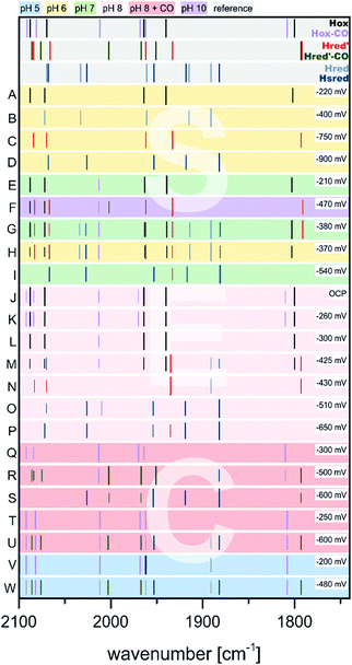 | ||
| Fig. 12 Schematic representation of IR band positions of electrochemically reduced CrHydA1 (coloured background) in comparison with currently known states (grey background). IR signatures of known states are taken from Table 2. References to entries: (A to D),80 (E to I),76 (J, K, N, O),58 (L, M, P to S),74 (T to W).70 | ||
Another transition of interest is Hred′ → Hred, which was addressed via H2 reduction experiments at different pH values by Stripp51 as well as Lubitz and coworkers.76 In these experiments, protein films of CrHydA1(ADT) were investigated for their IR band signatures at different pH values upon scanning the potential from −200 mV to −600 mV (Fig. 12, entries E to I). The IR signals at 1933 cm−1 and 1891 cm−1 were both found to have a maximum at −380 mV at pH 7, while being absent at −210 mV and −540 mV, respectively (Fig. 12, entries E, G, I). Originally, both IR bands were assigned to the same intermediate.58,60,74 However, at pH 10 the band at 1891 cm−1 cannot be found in the IR spectra during the potential scan, while the band at 1933 cm−1 occurs upon shifting to more reducing potentials (Fig. 12, entry F) and indicates a pH dependency of these IR bands. On the other hand, acidic conditions were shown to favour the species responsible for the band at 1891 cm−1 (Fig. 12, entry H). Due to the acidic conditions at which the latter species was observed, it was subsequently attributed to a reduced protonated form HredH+. (Note: HredH+ and Hred show the same IR band signature. We herein use both abbreviations to account for their different protonation state, which is not finally clarified and under severe debate within the community; for additional discussion see Section 3.10 ‘The catalytic cycle’ at the end of this section). Consequently, the band at 1933 cm−1 was assigned to an unprotonated reduced form, Hred′ (called Hred in the original literature). As a result of this study, the IR signatures of the single reduced H-cluster states Hred′ and Hred/HredH+ were assigned as 2084, 2066, 1962, 1933 and 1792 cm−1 for Hred′ and 2070, 2033, 1961, 1915 and 1891 cm−1 for Hred, respectively.76Hred′, the species assembling at alkaline pH, exhibits very small downshifts within the IR spectrum (3 to 7 cm−1) of the CO and CN− vibrations compared to Hox. A reduction of [4Fe]H in Hred′ is therefore more feasible than a reduced diiron site and is associated with higher shifts of the CO/CN− frequencies compared to Hox and Hred. Thus, transition from Hred′ to Hred is seemingly coupled to an electron transfer from [4Fe]H to [2Fe]H, which is orchestrated by the pH. If the proton pressure is sufficiently high to protonate the diiron site of Hred′ ([4Fe–4S]+–[FeIFeII]), the electron migrates from [4Fe]H to [2Fe]H, resulting in [4Fe–4S]2+–[FeIFeI]. According to Sommer et al., this value is pH 6, whereas Hred′ dominates already at pH 8 and both are equally present at pH 7.76 This delicate behaviour might be suitable for pH sensing, inducing subtle changes within the protein backbone upon going from Hred′ (alkaline) to Hred (acidic).72,76 The midpoint potential of the Hox → Hred′ transition was found to be −375 ± 10 mV vs. SHE with a strong pH-dependency determined by the protonation event at [2Fe]H. The latter event results in a plateau of the midpoint potential for high or low pH. For lower pH, the midpoint potential shifts by −50 mV from pH 7 to 6. This observation is also in line with the Hox-CO → Hred′-CO transition, which shows a linear behaviour with a potential shift of 55 mV pH−1 between pH 5 and 8. Both processes are consistent with a PCET from Hox to Hred′. While the molecular structure of Hred is thoroughly discussed in literature, up to now its structure was not finally confirmed.52,61,76,77,80,87,88
If the potential is swept to more reducing conditions as required for the Hred′ → Hred transition, a set of IR bands at 2068, 2026, 1953, 1918 and 1882 cm−1 that is similar to the pattern of Hred is observed. However, this set is slightly downshifted and better resembles the Hsred state that is known from NaDT and H2 reduction experiments.55,60 The small average downshift of about 5 cm−1 of the CO/CN− frequencies is in line with a reduction of [4Fe]H, as was observed for the Hox → Hred′ transition. The electronic structure of Hsred is therefore most likely a [4Fe–4S]+–[FeIFeI] state, which was already found by EPR spectroscopy as well (Section 3.4).55,60 The potential needed to accumulate Hsred is likewise pH dependent. At pH 7 and 8, Hsred is obtained as the major species at potentials <−510 mV vs. NHE (Fig. 12, entries O, P). Notably, at less cathodic potentials minor Hsred amounts are still present next to Hox and the single reduced species Hred′ and Hred (Fig. 12, entries G, I, M). If the proton concentration is increased to pH 5, i.e. conditions that favour the formation of Hred, Hsred is accessed more easily and found already at potentials of −480 mV. However, at pH 10, i.e. conditions that favour Hred′ over Hred, Hsred cannot be found.76 This behaviour of Hsred indicates that it is potentially formed from Hred in the reaction cycle, whereas it cannot be accessed from Hred′.
3.7 Influence of alternative dithiolate bridges on the reactivity of the H-cluster
One of the most striking advantages of the (semi-)artificial maturation process (Section 2.2) is the possibility to implement H-cluster mimics that are different from native CrHydA1(ADT) enabling altered reactivity patterns of the hybrid-enzymes.31 These differences in reactivity can then be utilised to target specific H-cluster states and transitions that are otherwise not observable within the native enzymes due to rival reaction pathways, e.g.Hred′ → Hredvs.Hred′ → Hhyd or the simultaneous enrichment of multiple states. Such an enrichment of multiple states severely hampers a precise analysis and leads to discrepancies when putting together all the mechanistic puzzle pieces. However, only in case of a similar electronic structures of both, native ADT and the semiartificial enzymes, respectively, proper statements on the various pathways and intermediates are valid. Otherwise the spectroscopically obtained results cannot be transferred from the semiartificial enzyme to the native ADT containing enzyme. For example, a comparable electronic structure of CrHydA1(PDT) compared to the native enzyme can be anticipated due to the similar IR band positions of their CO stretching frequencies, e.g. in the Hox resting state.74 Likewise, the molecular structures of the semiartificial enzyme variants PDT, EDT, ODT and SDT with a propanedithiolate, ethanedithiolate, oxadithiolate and a thiadithiolate bridge are presented in Fig. 13. In all cases, the artificial H-clusters closely resemble the native [FeFe]-hydrogenase with a bridging carbonyl and an open binding site at the distal iron atom under cryogenic conditions of the XRD experiments.89 The principle of CO-ligand rearrangement that occurs upon artificial maturation, i.e. loss of one carbonyl and adopting the rotated structure, is therefore independent of the bridging moiety and seems to be a general feature of [2Fe]H mimics – at least as long as the steric bulk within the mimic does not prevent accessing the maturation channel.31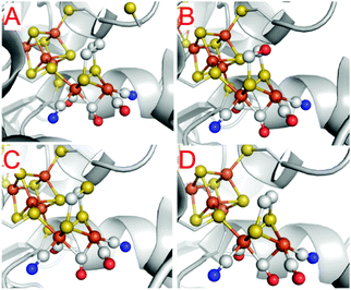 | ||
| Fig. 13 Molecular structures of the H-cluster from C. pasteurianum artificially maturated with (A) propanedithiolate (PDT), (B) ethanedithiolate (EDT), (C) thiadithiolate (SDT) and (D) oxadithiolate (ODT) containing [2Fe]H clusters. PDB entries 5BYR (PDT), 6H63 (EDT), 5BYQ (ODT), 5BYS (SDT). | ||
One of the most frequent alteration of [FeFe]-hydrogenases in literature concerning bridgehead variations in the enzyme and likewise in biomimetic catalysts (see Section 4) is the utilization of the PDT variant (Fig. 13A). Depending on the maturation conditions, it exclusively adopts either Hox or Hred′ upon maturation. Notably, the PDT variants lack the possibility to enter the Hred, Hsred as well as Hhyd states due to the missing amine functionality and therefore the possibility to undergo an intramolecular PCET from Hred′ to Hred or a classical PCET to Hhyd.31,51,76,90
The Hox state of PDT shows an IR spectrum that is equal to that of HADTox showing overall similar electronic situations as well as symmetry and thus support the identical structural features found by XRD experiments in their solid state.51,52,74,90 Likewise, the EPR spectrum of HPDTox resembles that of HADTox, showing a rhombic signal centred at 2.1 (g = 2.094, 2.039, 1.998) further supporting the anticipated [4Fe–4S]2+–[FeIIFeI] state already deduced from FTIR/DFT studies.74 Under 100% H2 at pH 8, HPDTox undergoes a one-electron reduction and fully converts a single product, namely HPDTred′. This observation is in stark contrast to the ADT samples, in which Hred and Hsred are found as well.55,59,60,67 Furthermore, the IR spectrum of HPDTred′ shows CN− vibrations at 2084 cm−1 and 2065 cm−1 as well as vibrations of the CO ligands at 1962, 1934 cm−1 and 1798 cm−1 which are comparable to those of the HADTred′ spectrum.51 Increasing the proton concentration from pH 8 to 4 while keeping H2 reducing conditions led in case of ADT to the formation of Hhyd.75 However, since the PDT analogue is not capable to adopt the Hhyd state, another state accumulates under these conditions that shows minor upshifted IR frequencies of all CN−/CO vibrations as compared to Hred′, i.e. 2084, 2068, 1966, 1938 and 1802 cm−1. A similar shift was observed for ADT upon reducing HydA1 at pH 4 with 2 equiv. NaDT and was denoted to a protonation of cysteine S9 at the [4Fe]H. This state was called HoxH accounting for the additional protonation (Fig. 7). According to DFT calculations, the same protonation was suggested for Hred′. The new upshifted band pattern found in PDT is therefore best explained by a second protonation at one of the [4Fe]H binding cysteines. According to DFT studies, cysteine S9 is highly favoured as potential protonation site.51 Due to the additional proton, the new double protonated state is called Hred′H. Notably, this state cannot be found in ADT, since then only Hhyd is found under otherwise identical conditions as reported for Hred′H.75
Furthermore, H2 reduction experiments on CrHydA1(PDT) show that the Hox and Hred′ analogues can be very easily enriched to purity. While high purity Hox samples can also be obtained in case of HydA1(ADT), Hred′ commonly comes along with Hred and Hsred, especially at pH ≤ 7. Nevertheless, Lubitz and coworkers were capable to determine the potential of the Hox → Hred′ transition of HydA1(ADT) to be −375 ± 10 mV vs. SHE.76 A linear correlation between Hox and Hred′ was found for the CO inhibited species, which are not able to form a reduced [2Fe]H-cluster species.70 Contrary, utilising PDT enzyme derivatives enables a direct investigation of the Hox → Hred′ transition e.g. by SEC-IR techniques without the need of CO inhibition and without side reactions.
Fig. 14 presents the Pourbaix diagram of the transition potentials for Hox → Hred′ (black) and HoxH → Hred′H (blue) as function of pH value following the peak intensity of the respective marker bands at 1941 cm−1 (Hox), 1934 cm−1 (Hred′), 1945 cm−1 (HoxH) and 1938 cm−1 (Hred′H) as well as subsequent lowering the applied potential from −100 mV to −800 mV vs. NHE.52 The E/pH-slopes of 55 ± 5 mV pH−1 (Hox → Hred′, black) and 50 ± 3 mV pH−1 (HoxH → Hred′H, blue) indicate a proton coupled reduction of the H-cluster (PCET). Furthermore, the 50 mV lowered reduction potential required for the HoxH → Hred′H transition suggests a protonation of [4Fe]H directly affecting the transition potential. This pH dependent transition from HoxH to Hred′H is clearly located above the H/H2 reference line (red), which also explains the spontaneous reduction of HoxH in the presence of H2.52 These results are in contrast to the earlier results on the Hox → Hred′ transition in CrHydA1(PDT) revealing a midpoint potential of −345 mV at pH 8.74 The respective transition potentials deviate by approximately 130 mV. This discrepancy was, however, hitherto not addressed in the literature afterwards and remains undissolved so far.
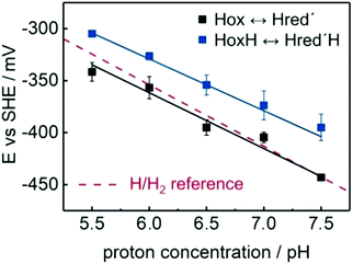 | ||
| Fig. 14 Pourbaix diagram showing the transition potentials for Hox → Hred′ (black) and HoxH → Hred′H (blue) as function of pH value. The slopes are 55 ± 5 mV pH−1 (black) and 50 ± 3 mV pH−1 (blue) with an approximate off-set of 50 mV that elevates the HoxH → Hred′H potential above the H/H2 reference (red traces, 59 mV pH−1). Error bars illustrate the quality of the Nernstian fit. Figure and caption are adopted with permission from reference. Reprinted from ref. 52 with permission from John Wiley and Sons, Copyright 2017. | ||
The results of these spectroelectrochemical experiments on CrHydA1(PDT) support the assumption of a proton dependent reduction of the [4Fe–4S]-cluster in Hred′.51 Whereas the formation of Hred requires the protonation of the native adt bridge, the very same protonation is inhibited due to the absence of the amine in PDT samples.76 In both cases, a PCET step directs the additional charge either to the [4Fe]H or [2Fe]H. The results on CrHydA1(PDT) are in line with the findings for a CO inhibited species of CrHydA1(ADT), which shows a 60 mV pH−1 linear correlation between the Hox-CO → Hred′-CO midpoint potential and pH. However, the transition to Hred′, in case of the CO inhibited species, is overall 70 mV more cathodic, showing the influence of the additional CO ligand substitution and leads to an increased electron density at [4Fe]H and therefore an inhibited reducibility.64,91 The Hox → Hred′ transition in non-inhibited CrHydA1(ADT) was determined to be −353 ± 10 mV vs. SHE at pH 7. Compared to the results of CrHydA1(PDT), the midpoint potential of the native enzyme is approx. 50 mV more anodic.76 The selective conversion from Hox to Hred′ was further utilized to address the concentration dependency of the formation rate of Hred′. Diluting the enzyme within bovine serum albumin (BSA) results in a severe drop of the Hox → Hred′ conversion rate.51 This behaviour was explained by an intermolecular electron transfer (disproportionation) between different [FeFe]-hydrogenase enzymes via two-electron reduced species formed upon treatment with H2. Likewise, a comparable behaviour was found in whole cell experiments utilising CrHydA1 expressed in E. coli. Monitoring the IR signatures of the H-cluster while purging E. coli cells with 1% H2 (99% N2), did neither reveal the specific marker band of Hred′ (1933 cm−1) nor Hsred (1882 cm−1). Both states possess a reduced [4Fe–4S]-cluster, which obviously is hardly trappable in living cells.35
Contrary to such reduced states, CrHydA1(PDT) and other hybrids (e.g. CrHydA1(SDT), CrHydA1(EDT) and CrHydA1(ODT)) enabled the selective formation of Hox upon prolonged exposure to N2 at pH ≥ 8 (auto-oxidation). The CN− and CO frequencies (Table 3) of EDT and SDT resemble those of the ADT and PDT variants, indicating an equal electron density at the Fe-centres. According to quantum chemical calculations at QM/MM and DFT levels of theory, the overall electronic configuration of all hybrid-enzymes was likewise suggested to be equal to ADT.67
| State | ν(CN−)/cm−1 | ν(CO)/cm−1 | Ref. | State | ν(CN−)/cm−1 | ν(CO)/cm−1 | Ref. |
|---|---|---|---|---|---|---|---|
| PDT | EDT | ||||||
| H ox | 2090, 2073 | 1965, 1941, 1810 | 52 | H ox | 2090, 2074 | 1965, 1941, 1809 | 67 |
| H ox -CO | 2094, 2083 | 2014, 1972, 1965, 1812 | H ox -CO | 2094, 2081 | 2019, 1975, 1967, 1812 | 67 | |
| H ox H | 2090, 2075 | 1969, 1945, 1814 | 52 | H ox H | 2094, 2076 | 1969, 1945, 1814 | 67 |
| H ox H-CO | 2095, 2086 | 2013, 1974, 1968, 1816 | H ox H-CO | 2098, 2087 | 2071, 1974, 1968, 1819 | 67 | |
| H red′ | 2084, 2066 | 1963, 1934, 1798 | 52 | H red′ | 2085, 2067 | 1961, 1933, 1798 | 67 |
| H red′ -CO | Not observed | H red′ -CO | 2091, 2080 | 2015, 1971, 1956, 1807 | 67 | ||
| H red′ H | 2084, 2068 | 1966, 1938, 1802 | 52 | ||||
| ODT | SDT | ||||||
| H ox | 2086, 2070 | 1972, 1948, 1812 | 75 | H ox | 2088, 2070 | 1969, 1942, 1810 | 67 |
| H ox -CO | 2096, 2085 | 2038, 1979, 1967, 1811 | 67 | H ox -CO | 2094, 2081 | 2019, 1975, 1967, 1812 | 67 |
| H ox H | 2093, 2078 | 1974, 1950, 1813 | 67 | H ox H | 2091, 2076 | 1974, 1950, 1814 | 67 |
| H ox H-CO | 2096, 2087 | 2032, 1980, 1971, 1815 | 67 | H ox H-CO | 2096, 2085 | 2020, 1978, 1971, 1816 | 67 |
| H red′ | 2083, 2070 | 1964, 1943, 1804 | 67 | H red′ | Not observed | 67 | |
| H red′ -CO | 2095, 2081 | 2011, 1978, 1930, 1806 | 67 | H red′ -CO | Not attempted | 67 | |
| H hyd | 2081, 2076 | 1978, 1962, 1862 | 75 | ||||
Under an atmosphere of 1% CO, all hybrid-enzymes in their oxidised forms adopt the Hox-CO state with the known IR band signature. However, while ADT, ODT and EDT immediately form Hox-CO with near quantitative yields, SDT and PDT revealed slower kinetics and adopt the Hox-CO state only in 65% and 20% yield, respectively. Even in an atmosphere of 100% CO, those two hybrids do not fully convert to the CO inhibited form. In line with those CO inhibition experiments, the decay of Hox-CO to Hox is very fast for SDT and PDT, while it is slow for EDT and very slow and incomplete for ODT and the native ADT forms. In Section 3.3, we already discussed the CO inhibition of CrHydA1 and mentioned the possibility of an apical CN− ligand in Hox-CO based on a partial rotation of dCN− in Hox.59 The rotation of Fed to an apical cyanide ligand in its CO inhibited form might explain the different reactivity of the hybrid enzymes towards CO: While ADT stabilises negatively charged ligands in apical position such as CN− or H−![[thin space (1/6-em)]](https://www.rsc.org/images/entities/char_2009.gif) 78 and thus explains the fast CO inhibition and slow decay of Hox-COADT, the other hybrids lack the possibility to form this hydrogen bond. Instead, destabilisation of an apical cyanide leading to an altered kinetic was suggested. Further influences of the non-ADT bridgeheads are the steric repulsion in case of SDT and PDT or electrostatic attractions for ODT and likewise SDT. EDT seems to be unbiased due to the missing bridgehead. Therefore, no stabilising or destabilising effects occur resulting in fast CO inhibition and decelerated Hox-CO decay.67 Although obvious differences regarding the distal cyanide ligand between native ADT and the hybrid enzymes are present, the CN− frequencies within their IR spectra do not change. This observation cannot be explained from inner sphere ligand coordination and supports the necessity to also discuss outer sphere coordination, i.e. towards the protein environment. This potential influence will be discussed in a separate section concerning the proton transfer pathway (Section 3.8).
78 and thus explains the fast CO inhibition and slow decay of Hox-COADT, the other hybrids lack the possibility to form this hydrogen bond. Instead, destabilisation of an apical cyanide leading to an altered kinetic was suggested. Further influences of the non-ADT bridgeheads are the steric repulsion in case of SDT and PDT or electrostatic attractions for ODT and likewise SDT. EDT seems to be unbiased due to the missing bridgehead. Therefore, no stabilising or destabilising effects occur resulting in fast CO inhibition and decelerated Hox-CO decay.67 Although obvious differences regarding the distal cyanide ligand between native ADT and the hybrid enzymes are present, the CN− frequencies within their IR spectra do not change. This observation cannot be explained from inner sphere ligand coordination and supports the necessity to also discuss outer sphere coordination, i.e. towards the protein environment. This potential influence will be discussed in a separate section concerning the proton transfer pathway (Section 3.8).
Like for CrHydA1(PDT), hybrid enzymes containing ODT, EDT and SDT bridgeheads were tested for their ability to oxidise H2, thereby adopting the reduced H-cluster states. We already discussed, that PDT does not adopt a diiron-site-reduced form (Hred, Hred, Hhyd) but is trapped in Hred′ upon reduction with H2.31,51,52,67 Whereas SDT stays in the Hox state, indicating no reaction with H2, EDT accumulates the Hhyd state after initial formation of Hred′ but returns to Hox very fast in case of dwindling H2. Contrary, the ODT version accumulates Hhyd under H2 at a very low reaction rate, which was explained by the diminished ability of the ether headgroup to heterolytically support cleavage of H2, while for ADT Hhyd was accumulated at low pH and simultaneous H2 or NaDT reduction.75,78 Likewise, the regain of Hox from ODT upon switching from H2 to N2, is slower compared to ADT, but faster compared to EDT. In retrospect, it was shown that the amine base of the native H-cluster is of substantial importance, not only for the H2 development, but also for H2 oxidation, by stabilising the apical hydride via a hydrogen bond between NH and H−.75,78 As in Hox-CO, with a proposed apical CN− ligand, this stabilisation is the reason for the different formation and decay rates of ADT vs. hybrid-enzymes, in which an outer-sphere coordination was suggested to stabilise Hhyd and Hox-CO.
The IR spectrum of HODThyd (2081, 2068, 1978, 1962 and 1868 cm−1) shows blue shifted CO bands compared to HODTox, which indicates a decreased electron density within the [2Fe]H-cluster. A FeIIFeII configuration and a reduced [4Fe–4S]+-cluster most accurately explains this finding and is further supported by the characteristic EPR signal of reduced [4Fe–4S]-clusters adopting the same redox state as found in HADThyd.84 The Hhyd state is best described with a terminal H− at the apical position of Fed and was indirectly observed by the different kinetics of hybrid-enzymes and further exploited from H/D exchange experiments revealing the bridging CO in trans position to the apical ligand of Fed. Due to the trans effect, an H/D exchange trans to μ-CO, results in a downshifted frequency of the bridging CO and indeed this shift is observed in FTIR experiments performed on CrHydA1(ODT). The bands of the terminal CO and CN− did not shift upon the H/D exchange.75,84 Likewise, NRVS measurements on CrHydA1(ODT) displayed high energy bands at 670 cm−1 and 727 cm−1 for the bending of a terminally bound hydride (Fed–H), which shifts towards lower energy (564 cm−1 and 625 cm−1) in case of a D2O/D2 environment.84 Notably, the results from nuclear resonance vibrational spectroscopy (NRVS) experiments on CrHydA1(ODT) differ from those on ADT, which gave significantly different bands for Fed–H at 675 cm−1 and 744 cm−1, respectively.78 The DFT based model of Hhyd from the NRVS measurements on CrHydA1(ADT) suggests a hydrogen bond between the terminal hydride and the amine headgroup, which cannot be formed in case of the ether moiety of ODT. Although serving as good model for the terminal hydride due to the accumulation of Hhyd, the ODT variant of the H-cluster is not able to correctly mimic the hydrogen bonding network between Cys169, NH and Fed–H, which is of eminent importance for the reactivity of [FeFe]-hydrogenases.78 A further possibility to enrich pure Hhyd is to impair the proton transfer activity within the enzyme. This can be performed by site directed mutagenesis (SDM) of amino acids within the proton transfer pathway (PTP).64,75,84–86,92
3.8 Influence of the proton transfer pathway and mutations thereof on the reactivity of the H-cluster
The main trajectory for protons between bulk water and the H-cluster is formed by an H-bond network between the side chains of the five amino acids R286, E282, S319, E279 and C299 (from the surface to the H-cluster, numbering corresponds to CpI), two water molecules Wat826 and Wat1120 (cumulated as W1 in Fig. 15, PDB-ID 4XDC, chain B) and the secondary amine of [2Fe]H.79,93,94 In order to address all amino acids to an individually adequate extend, we will start discussing the most inner located amino acid C299 (C169 in CrHydA1) and its mutants and continue going outwards residue by residue. The first amino acid that undergoes a weak hydrogen bond to the NH moiety of the H-cluster is cysteine C299/C169 (CpI/CrHydA1). This side chain is 3.5 Å away from the amine based on the crystal structure 4XDC of CpI. A second hydrogen bond (3.2 Å) is formed between the thiol moiety of C299/C169 and W1.79 This inner core of the H-bond network stays rigid during proton uptake and release independent of the H-cluster redox state as shown by IR spectrocopy.95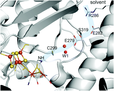 | ||
| Fig. 15 Proton Transfer Pathway (PTP) of [FeFe]-hydrogenase I from Clostridium pasteurianum between bulk water and the H-cluster via R286(R148), E282(E144), S319(S189), E279(E141), water complex W1 and C299(C169). Amino acid codes in parentheses are the respective residues in CrHydA1. Protein structure from PDB entry 4XDC. | ||
Due to the direct interaction of C299/C169 and the amine of [2Fe]H, this amino acid was the target of numerous mutagenesis studies.64,67,79,85,86,92,96 All performed modifications result in a diminished hydrogenase specific activity, which reflects the importance of the interplay between the cysteine's thiol group, the adjacent water complex and the amine bridge. Most modifications at this position were performed to enrich the H-cluster redox state Hhyd. Since it was found that a lack of the proton shuttling ability of the [FeFe]-hydrogenases, e.g. by changing ADT to ODT75,84 or blocking the proton transfer pathway Hhyd can be enriched, C299A/C169A64,85 and C299S/C169S86,92,96 mutants of CpI or CrHydA1 were used to trap the enzyme in Hhyd for further spectroscopic investigations of this state. Remarkably, the crystal structure of the C299ACpI mutant (Fig. 16A, green) shows an additional water molecule WC299A occupying the vacant space of the cysteine's thiol. However, this water molecule is not capable to restore the complete enzymatic activity of the mutant but accepts a proton from the H-cluster upon H2 oxidation also leading to an enrichment of the Hhyd state.79 In contrast to alanine and serine mutants, which show less than 0.2% of the hydrogenase specific activity, the C299D/C169D mutants show 25% and 65% remaining activity, respectively (Table 4). The pH-dependent activity optimum of C299DCpI, however, is shifted from pH 8 (native) to pH 6.5 and shows an altered but intact protonation equilibrium within the PTP.79
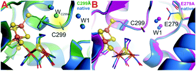 | ||
| Fig. 16 Native CpI(ADT) in comparison with its mutants CpI-C299A (A, green) and CpI-E279A (B, magenta). In case of the C299A mutant, water W* adopts the position of the absent thiol. Protein structures from PDB entries 4XDC (native), 6GLY (C299A) and 51A3 (E279A). | ||
| CpI mutant | H2-Production activity/% | CrHydA1 mutant | H2-Production activity/% |
|---|---|---|---|
| C299A | 0 | C169A | 0 |
| C299D | 30 | C169D | 65 |
| C299S | 0.05 | C169S | 0.1 |
| E279Q | 0.65 | E279Q | 0.2 |
| E279A | 0.06 | E279A | 0.1 |
| E279D | 30 | E279D | 5 |
| S319A | 5 | S189A | 10 |
| E282Q | 5 | E144Q | 0.45 |
| E282A | 60 | E144A | 45 |
| E282D | 80 | E144D | 50 |
| R286A | 90 | R148A | 55 |
| R286L | 300 |
The next amino acid of the proton transfer path is glutamic acid E279/E141, which strongly interacts with W1 (2.5 Å) via a stable trans complex.97,98 Furthermore, it only weakly interacts with S319/S189 (3.6 Å), indicating a discontinued proton transfer in the Hox state. Stripp and coworkers determined E279/E141 as the key residue upon switching from proton release to its uptake.95 Adjusting the CrHydA1 to Hred requires a proton from the PTP to enter the H-cluster, i.e. proton uptake reactivity.51,76 According to IR spectroscopy, E141 of CrHydA1 thereby forms an H-bond to S189 closing the gap between the inner and outer core of the PTP and enables a more continuous proton transport. In line with these results, E141DCrHydA1 loses 90% of its activity due to the longer distances between D141 and W1 and S189, respectively (Table 4).79 The remaining activity of glutamine and alanine mutants at this position is below 1%, indicating the complete loss of the proton transfer ability. In contrast to C299A, the crystal structure of E279A does not show an additional water molecule rescuing the proton transport (Fig. 16B), which explains the low residual remaining activity. In line, the mutant E279A adopts the Hhyd state under H2 oxidising conditions, since the proton transport pathway is interrupted at this position.79
S319/S189 is the first residue of the outer PTP and its side chain is 3.6 Å apart from E279/E141 and serves as H-bond acceptor during proton uptake. It further tightly interacts with E282/E144, which is only 2.8 Å apart, as H-bond acceptor and donor during proton release and uptake, respectively.95 Both mutants, S319A of CpI and S189A of CrHydA1 show approx. 5% activity regarding H2 evolution at pH 6.8 relative to the respective native enzymes (Table 4). The crystal structure of S319A from CpI (Fig. 17A) shows an additional water molecule WS319A, which does not exactly occupy the vacant –OH site of serine but is in proximity to E279 and E282 and closes the proton transfer path. As seen before in C299A, the makeshift water molecule changes the pH-dependent activity of the mutant to the highest activity between pH 6.5 and 7. However, in contrast to the C299A mutant, this modification does not lead to the accumulation of Hhyd under H2 oxidizing conditions but shows the reduced species Hred, Hsred and Hred′ besides Hox.
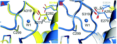 | ||
| Fig. 17 Native CpI(ADT) in comparison with its mutants CpI-S319A (A, yellow) and CpI-E282A (B, grey). In case of the S319A mutant, water WS319A adopts a position near the serine vacancy, closing the PTP. The crystal structure of E282A shows to invaded water molecules WE282A1 and WE282A2, one at the vacancy of the carboxylic acid and one more outwards, forming a makeshift proton pathway between bulk solvent and S319. Protein structures from PDB entries 4XDC (native), 6GM4 (S319A) and 6GM1 (E282A). | ||
Due to the missing possibility of S319A to form H-bonds to its neighbours, the next amino acid residue in the PTP, glutamic acid E282, points more towards the arginine residue R286 at the edge between enzyme and solvent. In native [FeFe]-hydrogenases, E282/E144 and S319/S189 interact via a hydrogen bond of 2.8 Å length. The deprotonated side chain might further form a salt bridge to the guanidine moiety of arginine R286.99 Mutants of E282/E144 show overall diminished activity regarding H2 evolution, which is, however, less pronounced as observed for e.g. E279/E141. Like for the more inwards positioned glutamic acid, E282Q/E144Q show only 5% and 0.5% remaining H2 release activity and a pH-dependent activity maximum between pH 6 and 6.5 according to the altered pKa value of the glutamine residue (Table 4). Remarkably, the aspartic acid mutants E282D/E144D show 80% and 50% remaining activity, respectively (Table 4). This contrasts the respective E279D/E141D mutants, which show significantly less activity. This discrepancy demonstrates the significance of the distinct amino acid residues for the catalytic PTP. However, the importance of proper amino acids within PTP appears to decrease from the H-cluster to the enzyme's surface. Interestingly, the E282A/E144A mutants show 60% and 50% residual activity, which again drastically differentiates E282/E144 from the inner laying E279/E144 (Table 4). The remarkable activity of these mutants most likely stems from two water molecules invading from the bulk solvent into the PTP (Fig. 17B). One is located directly at the vacancy of native E282, 2.5 Å away from the hydroxyl moiety of S319, and another one is placed more outwards in proximity to the bulk solvent, as revealed by XRD studies of E282A from CpI. Therefore, those water molecules build up an H-bond network from the solvent to S319, taking care of proton transfer in the outer core of the PTP. However, as previously described for other mutants, this is well in line with a slight shift of the maximal activity from pH 8 to pH 7.79 Besides its H-bond towards S319/S189, the side chain of the glutamic acid residue E282/E144 interacts with R286/R148, which is positively charged/protonated under physiological conditions and therefore forms a salt bridge with negatively charged/deprotonated E282/E144 of 2.8–3.1 Å.79,95 IR spectroscopic investigations on the R148 from CrHydA1 propose a neutral side chain during proton uptake (formation of Hred), which renders the arginine residue the first proton donor.95 A permanently neutral charge at the position of R286/R148 was achieved by the R286L mutant.93 Surprisingly, under conditions of non-rate limiting electron transport, i.e. using methyl viologen as mediator, the R286L mutant from CpI surpasses its native counterpart by the factor of three and is therefore the only mutant with increased activity in comparison to the native enzyme. This interesting finding was explained by the absence of the salt bridge between R286 and E282 that neutralises the negative charge of the carboxylic acid. In R286L, this charge is still present increasing the driving force for protons to enter the PTP.93,99 Furthermore, E282 is more exposed to the bulk solvent in R286L, as seen from Zn2+-inhibition experiments.
3.9 Influence of an additional F-domain on the reactivity of the H-cluster
The reactivity discussed so far is based on results from [FeFe]-hydrogenases HydA1 from C. reinhardtii. Especially due to the possibility to artificially maturate this enzyme, most research concentrates on this “blueprint” for H-cluster reactivity. The main difference between HydA1 and other [FeFe]-hydrogenases is the electron supporting chain of two [4Fe–4S]-clusters, so called F-clusters, which are absent in eukaryotic CrHydA1 but present in prokaryotic hydrogenases, e.g. DdH and CpI. The F-clusters will be denoted as d[4Fe]F (distal F-cluster, relative from the H-cluster) and p[4Fe]F (proximal F-cluster). We will stress the resulting differences in reactivity after describing the similarities between HydA1 and prokaryotic hydrogenases. The Hox state of CrHydA1, i.e. the smallest possible [FeFe]-hydrogenase, exhibits only the H-domain and is characterized by a rhombic EPR signal (g = 2.10, 2.037, 1.996), an IR signature with uncoupled vibrations for each CO/CN− ligand (2088, 2070, 1964, 1940, 1802 cm−1) and an electronic structure with an oxidised [4Fe–4S]2+ cluster and a bi-valent diiron site (FeIIFeI). Upon CO binding, the IR pattern changes to 2091, 2081, 2012, 1968, 1962 and 1808 cm−1, respectively, accounting for the additional CO ligand and the EPR spectrum changes from a rhombic to an axial signal (g = 2.052, 2.007). The IR spectra of Hox and Hox-CO from DdH (hydrogenase from D. desulfuricans) show characteristic signatures similar to Hox and Hox-CO from CrHydA1 (see Tables 2 and 3).56 Likewise, the EPR spectrum of DdH in the oxidised state agrees with the observed spectrum of HydA1 (see Table 1) but shows additional signals for the F-cluster.54,91 In case of Hox, a broad rhombic signal (g = 2.059, 1.935, 1.877) is present in the spectrum as well. This was assigned to d[4Fe]F since a spin coupling between the H-cluster and p[4Fe]F is expected and would result in an overall EPR silent state if the distal H-cluster is reduced.91 The overall electronic and molecular structure of the H-cluster in Hox and Hox-CO from CrHydA1 and DdH can therefore considered as identical, which is also in line with matching 57Fe hyperfine values, examined by HYSCORE spectroscopy, from both enzymes.49,71 However, differences occur for reduced enzymes.91 Under slightly reducing conditions, i.e. 50 μM NaDT, the IR spectrum of DdH(PDT) shows a mixture of HPDTox and HPDTred′. However, the typical rhombic signal of Hox in the EPR disappears, whereas the broader rhombic signal (g = 2.059, 1.935, 1.877) remains in the spectrum and another broad signal around g = 2.01 appears. This result was explained by an equilibrium between a state, in which both F-clusters are reduced and the H-cluster is oxidised (Fred/Fred/Hox), and a state in which the H-cluster and d[4Fe]F are reduced while p[4Fe]F is oxidised (Fred/Fox/Hred). In the former state, p[4Fe]F and the H-cluster combine to an electronically coupled cluster pair, resulting in an altered EPR spectrum compared Hox (broad g = 2.01), while in the latter state both, the H-cluster and the proximal F-cluster are EPR silent.91 To account for this equilibrium, the respective states are called Fred/Hox and Fox/Hred′ with both states bearing an EPR active reduced distal F-cluster. Notably, the IR maxima of e.g.Fred/Hox shift by approx. 1 cm−1 compared to Fox/Hox, which was observed in high-res SEC-IR experiments.91 Based on these EPR results, an effect of the cluster pairing regarding the transition potentials of the H-cluster is likely. The apparent midpoint potential of the Hox → Hred′ transition in DdH(PDT) is −500 mV vs. SHE at pH 8, which is certainly more negative than that observed for CrHydA1(PDT) (depending on the reference: 25 mV52 or 155 mV74 more negative). Furthermore, the two-state population, followed by IR spectroscopy, does not show a Nernstian behaviour. This is a result of redox anti-cooperativity, which was rationalised by simulating the resulting population curves. Therein, the extra electron upon reduction of Fox/Hox was allowed to equilibrate between p[4Fe]F (Fred/Hox) and [4Fe]H (Fox/Hred′), where the ratio was determined by the respective cluster potential. Taking the small IR band deviation of 1 cm−1 for reduced p[4Fe]F into account, the new four-state population curves became strictly Nernstian. The new model includes a reduction potential of [4Fe]H, which depends on the redox state of p[4Fe]F. If p[4Fe]F is already reduced, a more negative potential for [4Fe]H was observed and vice versa, i.e. redox anti-cooperative behaviour.91In CrHydA1, CO inhibition leads to increased electron density at [4Fe]H and results in a more negative reduction potential compared to non-inhibited species (Section 3.3). The same observation was found for DdH(ADT) as well. The potential shift of [4Fe]H is strong enough to prevent an equilibrium between Fred/Hox-CO and Fox/Hred′-CO due to the much more positive reduction potential of p[4Fe]F. Therefore, Fred/Hox-CO is exclusively present. To achieve Hred′-CO, a second electron is needed to enter the Fred/Hred′-CO state, which is again, as observed for DdH(PDT), formed at much more negative potential due to anti-cooperativity (Fig. 18). These findings explain why Hred′-CO in DdH cannot be observed under the conditions of CrHydA1.91
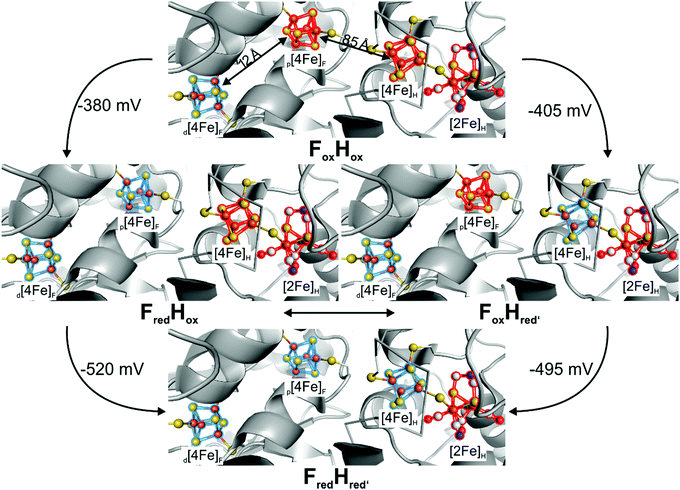 | ||
| Fig. 18 Four-state model of the redox-anticooperative effect, which results from the additional F-clusters in [FeFe]-hydrogenases (except HydA1). Clusters coloured in red are oxidized, clusters coloured in blue are reduced. Model depicted from ref. 91. | ||
Even more interesting is the comparison of CrHydA1(ADT) and DdH(ADT) since former shows a fascinating pH-dependent behaviour regarding single-electron reduced species: at alkaline pH (i.e. pH ≥ 8) Hred′ is favoured, while at acidic pH Hred is preferred (see Section 3.6).76 Due to the amine bridge, such a behaviour can be expected for DdH as well but is observed to another extent. At pH 6, Hred dominates upon reducing the potential, while Hred′ is not observed. This is in line with the findings from HydA1. Interestingly, Hsred, which replaces Hred at even more negative potentials in CrHydA1 cannot be found in DdH under the same conditions. The hypothesis explaining the absence of Hsred in DdH is that the second electron, required to form Hsred and finally liberate H2 can be stored in the F-clusters instead of the H-cluster. Due to the anti-cooperative effect of the additional [4Fe–4S]-cluster, the H-cluster's pKa shifts towards a value close to that of Hsred in HydA1. Therefore, bacterial hydrogenases may be able to skip Hsred (the participation of Hsred in the catalytic cycle is, however, anyway under debate) and directly form Hhyd. Hhyd was found in DdH under the same conditions as in CrHydA1, being low pH and constant H2 supply, showing the importance of this state in both organisms.80 Decreasing the proton concentration to pH 8 results in Hred′ being formed in HydA1. However, in DdH Hred is still the dominant species. Although the amount of both species in DdH increases simultaneously at potentials between −200 and −400 mV, Hred′ vanishes beyond this potential. According to simulations, the proximal F-cluster is reduced at approximately −400 mV, which results in an anti-cooperative effect and renders the reduction of [4Fe]H less likely to occur. Apparently, the pKa of the amine bridgehead shifts from ≈7.7 for HydA1 to ≈9.3 in DdH due to the redox anti-cooperativity.91 However, the influence of a protonation at the stabilising cysteine residue S9 of the [4Fe]H, which might be influenced by the reduction of the proximal F-cluster, was considered as possible explanation. This should be addressed in an additional study since the formation of HoxH under similar conditions as in CrHydA1 was reported for DdH as well. HoxH is associated with the H-cluster in oxidised form with an additional proton at cysteine S9, which causes minor (4 to 6 cm−1) IR band shifts.51 The complex situation of two different protonation events (cysteine S9 and adt) besides the three different reducible clusters (p[4Fe]F, [4Fe]H and [2Fe]H) makes the interplay of protons and electrons in DdH a very interesting topic to study albeit a challenging one.
Like DdH, hydrogenase I from C. acetobutylicum (CaI) bears two additional F-clusters next to the H-cluster within the protein frame. Compared to CrHydA1 and DdH, the IR spectrum from auto-oxidised CaI in the Hox state shows slightly downshifted CN− (2082 cm−1 and 2070 cm−1) and upshifted CO stretching frequencies (1969, 1646 and 1800 cm−1). The EPR spectrum, however, closely resembles that of DdH and CrHydA1 showing a rhombic 2.1 signal (g = 2.009, 2.039, 1.999).100 At acidic pH, the IR bands slightly shift towards higher wavenumbers, as was observed for CrHydA1 and DdH in the Hox → HoxH conversion as well, which indicates a similar reactivity at this point.51,101 Due to the accessory F-clusters, the reactivity of CaI seems to be very close to that of DdH.91 At pH 8, upon reducing the enzyme by NaDT or by photocatalytic electron supply, Hred is formed indicated by the marker band at 1899 cm−1 within the IR spectrum, whereas Hred′ is dominant under these conditions in HydA1. The reduction is likewise accompanied with a seemingly broad rhombic signals within the EPR spectrum that can be assigned to the reduced F-clusters (g = 2.043, 1.941, 1.911 and g = 2.073, 1.930, 1.868), which was also observed in DdH.91,100
At 13 K, the IR spectrum of NaDT reduced CaI shows bands at 2055, 2040, 1921, 1899 and 1801 cm−1. More interestingly, a μ-CO band is observed under these conditions. As previously described for CrHydA1, this may arise from the cryogenic conditions at which the spectrum was recorded.77,102 Changing conditions to D2O did not yield any observable shifts, which renders a terminal bound hydride at Fed unlikely. Unfortunately, no room temperature data are available to discuss the existence of a bridging CO vs. a bridging H−, which is proposed as one possible structure of a single-reduced H-cluster intermediate as well.80
Experiments on CrHydA1, in which specific amino acids were exchanged by site directed mutagenesis showed that e.g.Hhyd is enriched without the need of increasing both, proton concentration and H2 pressure.75 This is also true for CaI, whose IR spectrum shows the presence of two formerly unobserved species at room temperature upon changing C298 to Serine. Decreasing the temperature to 10 K results in the vanishing of bands at 2042 cm−1, 2022 cm−1, 1892 cm−1, 1978 cm−1 and 1781 cm−1, which were assigned to Hsred. The remaining bands at 2083 cm−1, 2067 cm−1, 1977 cm−1, 1964 cm−1 and 1851 cm−1 were assigned to Hhyd. The fact that both states, Hhyd and Hsred, are only observed if the proton path is blocked, renders them possible tautomers and endpoints of the catalytic H2 oxidation. As discussed above for DdH, the existence of reduced F-clusters can compensate the second reduction step from a single reduced to a double reduced H-cluster species before Hhyd is formed. There, Hsred is not observed and a proposed transient state in the HredH+ → Hhyd transition. Most likely, this is also the case for CaI since the F-clusters should show the same effect here. Additionally, H/D exchange experiments showed that the HredH+ → Hhyd transition is slower in case of D2O, resulting in accumulation of HredH+. The slowed kinetics implicate an intramolecular proton transfer for the transition from HredH+ to Hhyd. Both enzymes, DdH and CaI, exhibit additional F-clusters for electron relay and most likely changing the H-cluster's electronics. To determine the general function of these additional clusters, all enzymes excluding CrHydA1 should be investigated regarding their redox anti-cooperativity as performed on DdH. This includes enzymes from Clostridiae (CaI and CpI) and eventually HydS from T. maritima, which exhibits F-clusters as well and is known as sensory [FeFe]-hydrogenase.61 Sensory-type hydrogenases exhibit a third accessory [4Fe–4S]-cluster at the C-terminus, which is ligated by a Cx2Cx4Cx16C motif. Although the H-cluster of TmHydS is structurally the same as in CrHydA1, CaI and DdH, the reactivity of the sensory-type hydrogenase is dramatically different from the prototypical-type hydrogenases, which were described above. First indication of the altered reactivity is the 100-fold and 5-fold lower activity in H2 production and oxidation, respectively, of TmHydS compared to CrHydA1.61 This can be explained by the altered amino acid ligation of the H-cluster compared to e.g. CpI. While Cysteine (C299) is the endpoint of the PTP in prototypical CpI, an alanine (A131) occupies this position in TmHydS. Likewise, methionine residues M353 and M497, which are part of the H-cluster's coordination sphere in CpI, are replaced by G177 and S267 in TmHydS, respectively.103 Mutagenesis experiments of CpI showed that variants of respective amino acids, i.e. C299S, 353L and M497L, led to diminished activity as well.104 In addition, upon maturation of apo-HydS with an artificially synthesised H-cluster (under 2% H2), an IR spectrum with CN− bands at 2055 and 2022 cm−1 and CO bands at 1894, 1871 and 1763 cm−1 is observed (Table 5). While this pattern is not changed under reductive conditions (H2 or NaDT), oxidation with thionine led to an altered spectrum of 2088, 2079, 1971, 1947 and 1806 cm−1 that resembles Hox spectra of e.g. DdH and CaI. In conclusion, HydS exclusively adopts a reduced state under already minor amounts of reducing agents, which is not observed for other [FeFe]-hydrogenases. The latter shows major amounts of Hox upon maturation under the same conditions. The 30 to 80 cm−1 downshift vs.Hox of IR bands in the reduced state implies a reduction of [2Fe]H as in Hred of CrHydA1. However, the observed CO/CN− frequencies do not match those from Hred in HydA1, especially the observed μCO band in TmHydS cannot be associated to an Hred-like state (compare Tables 2 and 5). Therefore, the reduced state in TmHydS is called Hred*.
| State | ν(CN−)/cm−1 | ν(CO)/cm−1 | Ref. | State | ν(CN−)/cm−1 | ν(CO)/cm−1 | Ref. |
|---|---|---|---|---|---|---|---|
| DdH | Tm HydS | ||||||
| H ox | 2093, 2079 | 1965, 1940, 1802 | 75 | H ox | 2087, 2079 | 1971, 1947, 1806 | 61 |
| H ox H | 2097, 2082 | 1965, 1940, 1802 | 75 | H ox -CO | 2090 | 2016, 1973, 1964, 1805 | 61 |
| H ox -CO | 2096, 2089 | 2017, 1972, 1963, 1812 | 91 | H red* | 2055, 2022 | 1894, 1971, 1763 | 61 |
| H red | 2079, 2040 | 1915, 1892, 1962 | 75 | H sred* | 2047, 2013 | 1900, 1861, 1751 | 61 |
| H hyd | 2089, 2079 | 1980, 1963, 1860 | 75 | ||||
| Ca I | CpI | ||||||
| H ox | 2082, 2070 | 1969, 1646, 1800 | 101 | H ox | 2082, 2071 | 1970, 1947, 1800 | 75 |
| H red | 2052, 2035 | 1914, 1894 | 101 | H ox H | 2084, 2073 | 1975, 1953, 1809 | 75 |
| H red H + | 2055, 2040 | 1921, 1899, 1801 | 101 | H red | 2071, 2053 | 1915, 1899, 1962 | 75 |
| H hyd | 2080, 2063 | 1975, 1960, 1849 | 101 | H sred | 2065, 2039 | 1922, 1894, 1958 | 75 |
| H hyd | 2082, 2068 | 1984, 1968, 1856 | 75 | ||||
3.10 The catalytic cycle(s) of [FeFe]-hydrogenases
Despite the intensive investigation on the catalytic cycle of [FeFe]-hydrogenases in the last decades, up to today, not “one and only” working mechanism of this enzyme family is known. However, based on the reactivity described in this section, some cycles were suggested, which will be briefly described in this section. Especially, we aim at identifying similarities and major discrepancies of those cycles, which are mainly based on inconsistent findings on the reduced H-cluster states Hred and Hsred. It is evident from the results presented in this section that the exact nature of the states involved in the catalytic cycles is an ongoing matter of a lively debate in the community and hence we will leave the final judgement to the reader as we do believe that all of those currently reported mechanisms have strengths and weaknesses. We anticipate that future theoretical and experimental insights will lead to continuous reassessments and changes in the catalytic cycles.In Fig. 19–21, three proposed catalytic cycles are presented, which are adapted from a recent joint publication of the groups of Lubitz, Birrell and Dyer.105 From sub-turnover time-resolved IR spectroscopy, the authors derived cycle C, since all contained states were identified in their experiments. However, mechanisms A and B are very similar to C, considering the main H-cluster states Hox, Hred and Hhyd. All cycles start with Hox, which is the overall accepted entry point of the catalytic cycle. Hox is characterised by many different techniques (see above) as a [4Fe–4S]2+–[Fep2+Fed1+]-cluster with a bridging μ-CO ligand and an apical vacancy at the distal iron, with an eventually slightly apical rotated CN− ligand.29,49,64,67 From here, the first reduction event occurs at the [4Fe–4S]-cluster, which is especially plausible in hydrogenases with additional F-clusters as electron delivery chain but also true for HydA1, which lacks this chain of [4Fe–4S]-clusters.41,51,57,82 However, the exact mechanisms of the electron transfer are different in cycles A versus B and C. While in cycle B and C a simple electron transfer forms Hred, a PCET is responsible for Hred′ formation in cycle A. Hred′ is described similar to Hred, as a [4Fe–4S]1+–[Fep2+Fed1+]-complex with an Hox like molecular structure, but with an additional proton at one of the [4Fe–4S]-cluster stabilising cysteines (in blue colour in Fig. 20).51,52,88
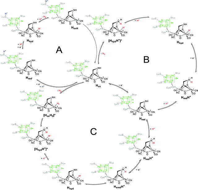 | ||
| Fig. 19 Main proposed catalytic cycles A–C adapted from ref. 87 and 105. | ||
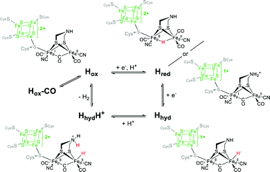 | ||
| Fig. 21 Schematic representation of the catalytic cycle of [FeFe]-hydrogenase, based on the states observed under whole-cell conditions including the protonated hydride species (HhydH+). Figure and caption from ref. 35. | ||
PCETs are common in nature and advantageous for a multi-electron process due to the balanced charge of the reduced moiety.106 In all cycles the next state, which could be trapped and thoroughly investigated by numerous different techniques is Hhyd. However, the mechanism to get there differentiates the cycles. While in cycle A a second PCET from Hred′ directly results in Hhyd, cycles B and C follow a successive mechanism of separate proton- and electron-transfer steps. A proton transfer to Hred results in the formation of HredH+, which electronic structure was characterized by Lubitz and coworkers as [4Fe–4S]2+–[Fep1+Fed1+] with a protonated amine bridgehead, which is why the additional electron from the four-iron cluster has to migrate to the diiron site.76 In cycle C, the following electron transfer forms HsredH+, that isomerises to Hhyd. In cycle B, the latter state is directly formed upon electron transfer. Considering the functionality of the amine bridge within the PTP, an intermediate with a protonated bridgehead is feasible – at least as very short-lived transient state – even in cycle A. This shows the hen-and-egg problem of a PCET, which may be facilitated via an electron–proton-transfer or an proton–electron-transfer.107
Starting from Hhyd, the second protonation of the H-cluster via the catalytic PTP results in the formation of H2 and the regain of Hox. In cycle A, the H-cluster passes through HoxH, an Hox-like state that still holds the non-catalytic proton near the [4Fe–4S]-cluster. Cycles B and C further contain the intermediate species Hox-H2 and/or HhydH+, which is feasible considering the role of the amine bridge. The HhydH+ state was recently observed in in vivo studies on HydA1 containing E. coli cells and is a plausible intermediate in the Hhyd → Hox conversion.35
Blanking out the non-catalytic proton in cycle A, cycles B and C can be considered as more detailed mechanisms of cycle A. All used H-cluster states share the Hox-like geometry with a bridging CO, which was supposed to be a prerequisite for fast turn over. However, in recent literature, structures containing a bridging hydride instead of a bridging CO were discussed as well.80,88 Those structures are thermodynamically more stable and therefore might not justify fast turn-over rates as observed for [FeFe]-hydrogenases, hence they were placed in a secondary cycle (Fig. 20) with exclusively bridging hydrides, which was formerly denoted as “slow cycle”.87 We already discussed that both single-electron-reduced states Hred′ and Hred can be formed upon reducing Hox and that pH dictates whether the electron resides at the [4Fe–4S]-cluster, stabilising the Hox-like structure at more alkaline pH, or migrates to the diiron subsite forming Hred (HredH+) at pH ≤ 6. At this point, a problem regarding the nomenclature of the specific states arises. The state which is entered as first species in all cycles, i.e. [4Fe–4S]1+–[Fep2+Fed1+], is called Hred76,77,105 or Hred′,51,72,87,88 depending on the additional proton near the [4Fe–4S]-cluster. The single-electron-reduced [4Fe–4S]2+–[Fep1+Fed1+] state is called Hred80,87,88 or HredH+,76,77,102,105 depending on the described intermediate and considered mechanism. The same is true for the double reduced state Hsred/HsredH+.
Unfortunately, no XRD studies that would give hints towards the spatial structure of those single reduced states are present. Therefore, EPR and vibrational spectroscopy in combination with computational techniques are the methods of choice to characterise the molecular structure of each Hcluster state. While EPR spectroscopy can electronically distinguish between [4Fe–4S]1+–[Fep2+Fed1+] and [4Fe–4S]2+–[Fep1+Fed1+], the determination of the actual structure requires better suited techniques. Along this line, Lubitz and coworkers proposed the structure of HredH+ in 2017 based on the pH dependency of this state (Section 3.6).76 Since the secondary amine is the most basic site within the H-cluster and simultaneously the endpoint of the catalytic PTP, a structure with a protonated bridge (NH2+) and a (semi-)bridging CO was justified. Later, this structure was further strengthened by IR und NRVS measurements. There, a bridging CO signal at 1810 and 1803 cm−1 was found within the IR spectrum of HredH+ and HsredH+, respectively. The absence of a high energy μ-H− band in the respective NRVS supported the assumption of a protonated amine bridge for these structures.77 As mentioned in Section 3.4, these measurements were, however, conducted at 40–70 K, rendering a direct comparison with spectroscopic results obtained at room temperature cumbersome. IR spectroscopy at room temperature did not show a bridging or semi-bridging CO ligand.51,72 However, in models without μ-CO ligands, the clear pH-dependent formation of Hred was addressed via a bridging hydride for Hred and Hsred incoming from the catalytic PTP (Fig. 20 left cycle).
Computational simulations on those structures were in overall good agreement with observed spectra.80Hox − Hred NRVS difference spectra revealed major differences at the [2Fe–2S]-subsite for Hred, whereas the [4Fe–4S]-cluster in Hred and Hox is identical. Again, simulations were carried out for a structure with a μ-H− ligand, which agreed well with the found spectra.80 Interestingly, a high energy band at approx. 750 cm−1 for a bridging hydride was absent in these simulation and present in simulation of Birrell and coworkers.77
The current data situation does not allow to favour one of the proposed structures for Hred/HredH+ and Hsred/HsredH+ in an unbiased fashion. However, the discussion on these H-cluster states indeed improved the knowledge on the working mechanism of [FeFe]-hydrogenases – at least, if in vitro measurements of isolated enzymes are considered. Recently, in vivo measurements on living E. coli cells that were genetically modified to express the hydrogenase HydA1 and artificially maturated with a synthetic precursor of the diiron site, were performed.35 Here, no [4Fe–4S]1+–[Fep2+Fed1+]-like state was found, instead Hred was enriched under 1% H2 (99% N2). Addition of 2 mM NaDT and acidification of the cells led to formation of HoxH. Additional treatment with H2 afforded Hhyd. Increasing the NaDT concentration to 100 mM enabled the detection of Hhyd even at pH 8. When the pH was lowered at these conditions, a new species with approx. 15 cm−1 upshifted CO bands compared to previously reported CO signals of Hhyd occurred. These signals were attributed to the HhydH+ species, comprising a protonated amine bridge, which was hard to enrich in isolated HydA1 and was therefore not characterised – although postulated (Fig. 20). This state is the missing link between Hhyd and Hox (Fig. 21) and provides insight into the H2 formation and cleavage.35
Part B: structural and functional models of [FeFe]-hydrogenases
IV Synthesis of H-cluster models – bridge alterations, metal exchange and ligand substitution
4.1 From enzymes to biomimetic H-cluster models
The pioneering progress in the analysis of natural systems led to the identification of the crucial framework and functional properties of the active site of [FeFe]-hydrogenases. Since the detailed structural characterisation of the natural system at the end of the last century,28,108 synthetic chemists have constantly devoted efforts towards mimicking the enzyme subsite. These mimics range from small transition metal dinuclear carbonyl clusters to elaborate artificial protein replications.31–33 However, it should herein be mentioned that [2Fe–2S]-mimics were already described in the early 20th century without the knowledge of the hydrogenases’ active site but paved the way towards the fundamental synthetic strategies to assemble these cluster mimics. It is furthermore noteworthy that with the exceptional work of Rauchfuss, Darensbourg and Pickett after the elucidation of the enzyme structure, the iron sulphur chemistry underwent a renaissance and became a significant part of bioorganometallic chemistry. The tremendous modification efforts to the catalytic subsite are mainly driven to either achieve ideal catalytic efficiency approaching that of the natural enzyme or to understand the underlaying catalytic mechanism which results in a hitherto unmatched proton reduction activity of the natural system. The diiron subsite can be modified in multiple ways, including e.g. the modification of the bridging S–S linker length, exchanging the bridging sulphur-atoms with other chalcogens or pnictogens, substitution of carbonyl ligands or even the incorporation of other metals. We herein attempt to provide a comprehensive overview on the plentiful modification options.4.2 H-cluster models with altered dithiolate bridges
![[double bond, length as m-dash]](https://www.rsc.org/images/entities/char_e001.gif) CR2 linker. Following this route, Fe2(μ-S2C
CR2 linker. Following this route, Fe2(μ-S2C![[double bond, length as m-dash]](https://www.rsc.org/images/entities/char_e001.gif) CHPh)(CO)6 (9) was obtained by the reaction of Fe3(CO)12 (10) and 2-phenylethenethione as well as its tautomer (2-phenylethyne-1-thiol). The low yield (4%) of the model yet remains unexplained due to the extensive and complicated chemistry of thiols with Fe3(CO)12.
CHPh)(CO)6 (9) was obtained by the reaction of Fe3(CO)12 (10) and 2-phenylethenethione as well as its tautomer (2-phenylethyne-1-thiol). The low yield (4%) of the model yet remains unexplained due to the extensive and complicated chemistry of thiols with Fe3(CO)12.
In that direction, Fe2(C8H12S3)(CO)6 (11, C8H12S3 = 3,3-dimethyl-4-(propan-2-ylidene)-thietane-2,2-bis(thiolate)) was obtained via the reaction of tetramethyl-1,3-cyclobutanedithione with Fe3(CO)12. A plausible synthetic mechanism for the formation of 11 involves the rearrangement of the dithione to a beta-thiolactone followed by sulphur insertion to yield the respective thiolene, which upon reacting with Fe3(CO)12 yields 11.
Furthermore, Fe2(μ-S2C![[double bond, length as m-dash]](https://www.rsc.org/images/entities/char_e001.gif) CHC(O)C6H4R)(CO)6 (12R, R = F, OMe) with unsaturated functionalities at the thiolate linker were described by Zamora and coworkers.111,112 While the reaction of Fe2(CO)9 (13) and (HS)2C
CHC(O)C6H4R)(CO)6 (12R, R = F, OMe) with unsaturated functionalities at the thiolate linker were described by Zamora and coworkers.111,112 While the reaction of Fe2(CO)9 (13) and (HS)2C![[double bond, length as m-dash]](https://www.rsc.org/images/entities/char_e001.gif) CHC(O)C6H4R in diethyl ether gave the respective saturated products (14R), a 1
CHC(O)C6H4R in diethyl ether gave the respective saturated products (14R), a 1![[thin space (1/6-em)]](https://www.rsc.org/images/entities/char_2009.gif) :
:![[thin space (1/6-em)]](https://www.rsc.org/images/entities/char_2009.gif) 1 molar ratio of Fe3(CO)12 and corresponding ligand in THF yielded the unsaturated product (12R) (Fig. 23). Upon further increasing the ligand amount, a mixture of both products was obtained. Although these models show structural similarities with the active site of the enzyme, they generally lack further investigations on their catalytic activity.
1 molar ratio of Fe3(CO)12 and corresponding ligand in THF yielded the unsaturated product (12R) (Fig. 23). Upon further increasing the ligand amount, a mixture of both products was obtained. Although these models show structural similarities with the active site of the enzyme, they generally lack further investigations on their catalytic activity.
 | ||
| Fig. 23 Influence of the reaction conditions on the product obtained as described by Toledano et al.111,112 | ||
With these synthetic possibilities at hand, various modifications have been carried out. Donovan et al. reported the modified analogues Fe2((SCHR)2)(CO)6 (16R, R = CH3, CH2OH) wherein methyl and hydroxymethyl groups were introduced to the ethanedithiolate linker.117 In the absence of any acid, the complexes displayed cathodic shifts in their reduction potential increasing with the number of methyl groups incorporated within the thiolate linker. When studied in the presence of e.g. 4-tert-butylphenol as a proton source, a catalytic peak was observed at approximately −2.2 V vs. Fc/Fc+ for all complexes. Along this line, Fe2(SCH2CH(CH2OH)S)(CO)6 (17) providing an additional hydroxyl group at the ethane bridge was synthesised to study the influence of hydrogen bonding within the protonation experiments. It was expected that the hydroxyl group can act as a proton shuttle. While Pickett and coworkers revealed a high degree of hydrogen bonding, which results in self-polymerised cyclic hexamers,118 the model was, however, catalytically inactive.117 In addition, the edt complex was modified with a sulfonate moiety to enable catalysis in water. Using ascorbic acid as a proton donor and [Ru(bpy)3]2+ as photosensitizer, the modified edt-complex was reported to generate 88 equivalents of H2 per catalyst equivalent.119
Edt-complexes can likewise be obtained by reaction of Fe2(SH)2(CO)6 and diketones – here, reactions e.g. with glyoxal or benzil resulted in the formation of Fe2((SC(OH)R)2)(CO)6 (18R, R = H or Ph, Fig. 24). The rigid unsaturated dithiolate linkers have been broadly known to assist in the facile reduction of the [2Fe–2S]-models via delocalisation of the charge density from the iron centres through p–π interaction.120
Likewise, the edt-model Fe2(SCH2C(S)![[double bond, length as m-dash]](https://www.rsc.org/images/entities/char_e001.gif) C
C![[double bond, length as m-dash]](https://www.rsc.org/images/entities/char_e001.gif) CH2)(CO)6 (19, Fig. 24) was synthesised by the reaction of Li2Fe2S2(CO)6 with excess 1,4-dichloro-2-butyne. Herein, the electron withdrawing nature of the substituent, reduces the electron density at the iron centre thereby resulting in slightly milder potentials for electrochemical reduction (−1.60 V vs. −1.66 V of Fe2(pdt)(CO)6 (20)). The unsubstituted diiron buta-2,3-diene-1,2-dithiolato model was found to be capable of proton reduction of CH3COOH with a low overpotential of −0.65 V in MeCN.121
CH2)(CO)6 (19, Fig. 24) was synthesised by the reaction of Li2Fe2S2(CO)6 with excess 1,4-dichloro-2-butyne. Herein, the electron withdrawing nature of the substituent, reduces the electron density at the iron centre thereby resulting in slightly milder potentials for electrochemical reduction (−1.60 V vs. −1.66 V of Fe2(pdt)(CO)6 (20)). The unsubstituted diiron buta-2,3-diene-1,2-dithiolato model was found to be capable of proton reduction of CH3COOH with a low overpotential of −0.65 V in MeCN.121
Since the rotated structure of the complexes bearing a bridging carbonyl group is a catalytically relevant key intermediate, studies were also conducted to estimate the influence of steric bulk at the dithiolate linker on stability of the rotated state. Here, model 21 with a rigid norbornane structure was synthesised from norbornyltrithiolane (exo-3,4,5-trithiatricyclo[5.2.1.0]decane) and Fe2(CO)9 and was subsequently studied using photoelectron spectroscopy in comparison to Fe2(pdt)(CO)6, Fe2(bdt)(CO)6 and 2,3-pyridinedithiolato analogues.122 While the reorganization energies of the 1,2-benzenedithiolate, 2,3-pyridinedithiolate, and 1,3-propanedithiolate complexes are comparable, the norbornane model revealed the largest overall reorganization energy. However, the reorganization energies of all models are small compared to the enzymatic active site and further corroborates the importance of the secondary coordination sphere on the proton reduction at unmatched biological rates.122
The PDT model was originally prepared from Fe(CO)5 by a reaction with tetrathiacyclophane in 30% yield.123 Later, this method was modified, and 1,3-dithianes were employed leading to an increased yield of 42%.124 Nowadays, the synthetic methodology of employing Fe3(CO)12 as the starting material along with propanedithiol enables excellent yields of up to 92% (Fig. 25).116
In general, Fe2(pdt)(CO)6 based analogues can be synthesised from the oxidative addition of cyclic disulphides to Fe2(CO)9 or by the reaction of the respective dithiols with Fe3(CO)12 (Fig. 25). These facile pathways usually lead to the desired complexes in high yields. Alternatively, reaction of Fe2S2(CO)6 with LiEt3BH, CF3COOH along with a suitable dihalide compound (R1R2C(CH2X)2 where X = Cl, Br) can be carried out as shown in Fig. 25. However, usually this method gives lower yields as compared to the first two pathways.
Examples of early modified Fe2(pdt)(CO)6 complexes date back to 1982, when Seyferth et al. investigated the reaction of Fe2(SH)2(CO)6 with mesityl oxide and α,β-unsaturated ketones in the presence of amines (e.g. triethylamine or piperidine) to afford complex 22.125 Another early report of this class of complexes described the synthesis of a model bearing valeric acid and its C1-functionalized derivatives. Comparably, complexes 23 to 25 were obtained upon treating Fe2(CO)9 with α-lipoic acid or its ester/amide derivatives in THF.126 Also, the unsymmetrical complex 26 bearing a cyclohepta-4,6-diene unit in the bridge has been reported and was obtained upon treating Fe2(CO)9 with the respective trithiolane compound (i.e. 2,3,4-trithiabicyclo[4,3,1]deca-6.8-diene) in THF.127
Likewise, as the nature of the bridging ligands exerts significant influence on the electrochemical properties of the models, their systematic study was thought to be essential. Hereby, models with longer (–S(CH2)nS–) (n = 4–8) dithiolate linkers were reported. Prior to reaction, however, disulphide formation was performed to suppress the formation of polymeric complexes and to favour the formation of the [2Fe–2S]-mimics. The required cyclic disulphides were obtained upon reacting the respective dithiols (HS(CH2)nSH) (n = 4 to 8) and iodine in a Et3N solution. Upon refluxing the disulphides with Fe3(CO)12, the respective sub-site mimics 27 to 31 were obtained. It was shown that oligomerization can hardly be suppressed leading to di-, tetra- as well as hexametallic complexes. Likewise, the increased length of the dithiolate linker had negligible influence on the electrochemical properties of the corresponding complexes.128
4.2.3.1 PDT models with C2-modifications at the dithiolate linker. Most alkyl chain C2-modifications of the dithiolate linker were – and still are – performed at the C2 position of the pdt-ligand. Although the general catalytic properties of the resulting model compounds cannot be altered to a significant extent, modified bridges do enable the alteration of physical properties, e.g. solubility, size and adhesive capabilities as well as the introduction of additional functional groups for the linking to surfaces or macromolecules.
Solubility is a key issue in HER-catalyst research and especially in larger scale, solvation in aqueous media is preferred for environmental reasons along with the parallel use of water as solvent and substrate. However, Fe2(pdt)(CO)6-like compounds comprise a bad solubility in water due to their non-polar character. Addressing this issue, the solubility of models is usually increased through CO-ligand substitution in favour of phosphines129,130 or by encapsulating the models in a water-soluble framework (e.g. dextrins131 or micelles132). The introduction of polar headgroups at the C2 position of the dithiolate linker is a further possibility to improve the solubility of the [2Fe]H-subsite models.
Weigand and coworkers showed that upon introducing sugar residues to the C2 position of 20 (Fig. 26) and Fe2(pdSe)(CO)6 (32) the biomimetic catalysts became water soluble.133 The synthesis of those compounds (33 and 34) followed the well-established route via reacting Fe3(CO)12 with the respective protected dithiol or diselenolane in tetrahydrofuran under reflux and a follow up deprotection of the sugar moiety with sodium methoxide. Interestingly, the selenium version shows an improved stability as well as activity regarding HER in aqueous media, which was explained by the increased electron-donating properties of selenium and therefore stronger π-backdonation to the CO ligand from the iron centres, resulting in a stronger Fe–C bond. Both models provided good solubility in H2O![[thin space (1/6-em)]](https://www.rsc.org/images/entities/char_2009.gif) :
:![[thin space (1/6-em)]](https://www.rsc.org/images/entities/char_2009.gif) MeCN (5
MeCN (5![[thin space (1/6-em)]](https://www.rsc.org/images/entities/char_2009.gif) :
:![[thin space (1/6-em)]](https://www.rsc.org/images/entities/char_2009.gif) 1) and acted as proton reducing catalysts using acetic acid or water as substrate.133
1) and acted as proton reducing catalysts using acetic acid or water as substrate.133
Besides sugar residues at the pdt-bridge, more simple models comprising a hydroxy group at the bridge exist as well. This model (35) was synthesised to gain information on the influence of the hydrogen bonding network between the single complexes in solution and to mimic the natural environment of the H-cluster.134 Using 1,3-disulfanylpropan-2-ol, a binuclear Fe2(pdt)(CO)6-like structure (35) was obtained, which is arranged in a helical structure in solid state forming H-bonds between the single hydroxy groups. For the longer butane linker 1,4-dithiothreitol, however, a cyclic tetranuclear complex (36) was formed, in which two dithiolate bridges coordinate two different Fe2(CO)6 moieties. In a follow up study, the hydroxy group in 35 was modified via two ways: (a) masked by a methyl group to investigate the influence of the oxygen atom without the hydrogen bonding network to neighbouring complexes (37) or (b) by adding an additional alkyl group to the C2 position of the pdt-bridge (38).135
Notably, such modifications do not alter the catalytic properties of the resulting cluster compared to the hydroxy derivative 35. These results once again show that derivatisation of the pdt-linker does not necessarily influence the catalytic mechanism of [FeFe]-hydrogenase models, unless pKa and electron density are dramatically changed. A change in reactivity, however, can be achieved by elongation of the C2–OH distance e.g. by implementing an additional methylene group in the bis(hydroxymethyl)-functionalised Fe2((ECH2)2C(CH2OH)2)(CO)6 (E = S (39), Se (40)) complexes.136 The solid state structure of those complexes also revealed a significant intermolecular H-bonding network, forming a rod-shaped cluster with tetrahedrally arranged OH groups. Notably, the reduction potential determined as E44 = −1.53 V and E45 = −1.49 V vs. Fc+/0, respectively, which is significantly anodically shifted due to facilitated structural changes upon reduction compared to PDT that exhibits its averaged first reduction at −1.66 V vs. Fc+/0 (see Section VI). Furthermore, as the resulting anionic species in solution is potentially stabilised via intermolecular hydrogen bonding from the hydroxymethyl moiety to either the Fe or the chalcogen atom, respectively. The anion was found to be capable of H2 production from CH3COOH via a proposed ECEC mechanism.136
Another way to modify OH-functionalized complexes is the subsequent derivatisation with a carboxylic chloride in presence of Et3N and offers a wide range of possible alterations. Song et al. described an alternative synthesis of 35 from Li2Fe2S2(CO)6 and 1,3-dibromo-2-propanol and further derivatised the OH-modified bridge (41 to 43R) as described in Fig. 27 to explore their influence on the catalytic properties.137 Herein, model 42 is of special interest, as the pendant phosphine coordinates to one of the iron centres, thereby resembling a closer [2Fe–3S] H-cluster model.138,139 However, electrocatalytic activity regarding proton reduction was yet solely reported for model 41 bearing the ketone group.137
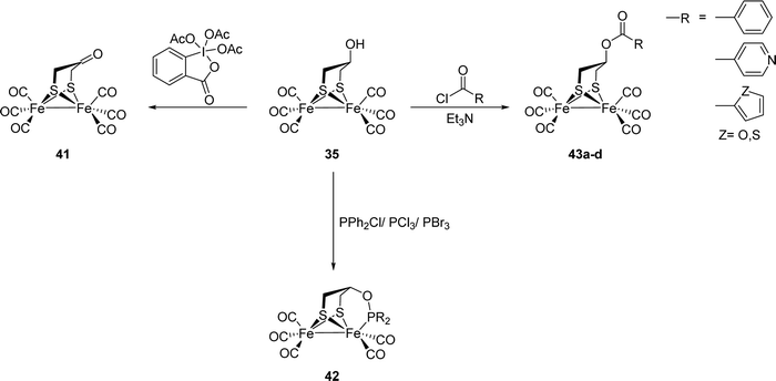 | ||
| Fig. 27 Representative modifications of OH-derivatized complexes.137 | ||
The structural features of a headgroup-bound ligand, which can coordinate to the iron centres as shown in complex 42, was also addressed by Pickett and coworkers.140 A series of models of the type Fe2((SCH2)2C(CH3)(CH2S-p-C6H4X)(CO)5) (X = CN (44), NO2 (45), NH2 (46)) and Fe2((SCH2)2C(CH3)(Y))(CO)5 (Y = 2-pyridine (47), CH2OH (48), CH2NH2 (49), CH2SMe (50)) was subsequently synthesised.138–140 It is worth mentioning that models 47 to 50 display a pH dependent CO-binding (“on” or “off”). The labile bridgehead substituent acts either as a chelating ligand or as a base. Upon protonation under CO-atmosphere the hexacarbonyl compound is generated, which can be reversed with addition of bases wherein ligand to CO displacement occurs. The influence of the coordination of the pendant thioether on the reactivity of 50 is discussed in Section 5.2.
Following organometallic advances, the interest to develop [2Fe]H analogues displaying better catalytic behaviour or which could be strategically integrated into electrocatalytic systems gained tremendous popularity.141–143 Thus, models with easily transformable functionalities such as carboxylic acid groups (51) were introduced to Fe2(pdt)(CO)6-like models by reacting Fe3(CO)12 with e.g. 1,2-dithiolane-4-carboxylic acid. The carboxyl group enables the functional binding of suitable amines via amide bond formation e.g. with aniline, and therefore allows the covalent attachment to amino-functionalized pyrolytic graphite electrode surfaces – interesting candidates for the design of heterogeneous electrocatalysts.141,144 The catalytic mechanisms and potentials after attachment of the Fe2(pdt)(CO)6-like model to the surface, seem to be unchanged compared to a “free” complex.
4.2.3.2 Chalcogenide and pnictogenide substituted PDT models. As mentioned in the previous section, the selenium version of a sugar-substituted Fe2(pdt)(CO)6-like complex shows a higher proton reduction activity and improved stability in aqueous media. To this end, various Se-substituted models (32, 52 to 55) were reported, which can be obtained by refluxing Fe3(CO)12 with either 1,3-diselenocyanatopropane, a modified diselenolane or 1,3,5-triselanacyclohexane (Fig. 28).145
In the same manner, models 56 to 58 bearing an oxetane ring were synthesized.146 The subsequent investigation of these chalcogenide substituted models regarding their proton reduction capabilities revealed a decreasing activity on moving from S- to Te-analogues owing to an increased Fe–Fe distance and hence disfavouring a bridging ligand, e.g. a hydride from direct protonation or a CO ligand from the so called “rotated state”.145,146 A further trend that can be observed upon changing sulphur to selenium or even tellurium is a decreasing reorganization energy for the reduction from a FeIFeI to a FeIFe0 cluster, which balances the increasing electron density at the iron centres due to the sulphur exchange with stronger electron donors.
Along this line, models with additional methylene groups inside the linker were synthesised via reaction of Fe3(CO)12 and the respective 1,2-thiaselenane or 1,2-thiatellurane (59 and 60).147 Using these models, likewise the change of the reorganization energy upon exchange of sulphur by its heavier homologues was studied and lowered energies were observed.148
Additionally, to study the influence of the steric bulk on the reduction properties, methyl substituents (61 and 62) were introduced on the bridgehead carbon of the diselenide linker.148 The altered reduction behaviour along with catalytic abilities of these complexes will be discussed in Section 6.3.
In addition to the above presented synthesis pathways, the reaction of dihalides and Fe2E2(CO)6 (E = S, Se, Te) is a further valuable approach (compare with Fig. 25). Following this synthetic scheme, Fe2((TeCH2)2CH2)(CO)6 (63) was obtained from the reaction of Fe2Te2(CO)6 and Br(CH2)3Br.149
Motivated by a lower acidity of phosphines (R2PH) as compared to the corresponding thiols, it was likewise postulated that diiron diphosphido models display an enhanced basicity of the iron centres resulting in stable terminal hydrides upon protonation.141,150–154 To achieve diiron diphosphido analogues, the diphosphines (CH2)n(PPhH)2 (n = 2, 3) were refluxed in the presence of Fe3(CO)12 affording complexes 64 and 65. Furthermore, these models were transformed to the diphosphine substituted analogues Fe2{(CH2)3(PPh)2)}(CO)4(κ2-dppv) (66a) and Fe2{(CH2)3(PPh)2)}(CO)4(κ2-dppbz) (66b). Due to the increased metal basicity they were predicted to undergo protonation at the metal centre. However, slow protonation at the metal centre resulting in a bridging hydride state was observed in low temperature experiments (−90 °C).155 For a detailed discussion of the protonation behaviour of H-cluster mimics see Section 5.3.
4.2.3.3 H-cluster models with other group 14 elements in the bridgehead position. The exchange of the C2 carbon for its heavier homologues (Fig. 29) strongly influences the properties of the resulting complexes. A report by Glass et al., for example, described the synthesis of a tin substituted hydrogenase analogue – Fe2((SCH2)2SnMe2)(CO)6 (67).156 The complex was obtained from Fe2(SH)2(CO)6, Me2Sn(CH2I)2 and Et3N. Later on, studies on a series of silicon modified dithiolato diiron models were described by Apfel et al.157 The Fe2((SCH2)2SiR1R2)(CO)6 (68 to 70, R1 = R2 = Me, (CH2)nn = 4, 5) complexes were obtained by reacting Fe3(CO)12 and the corresponding bis(mercaptomethyl)silanes. Moreover, the Si-bridged tetranuclear model (CO)6Fe2(SCH2)2Si(CH2S)2Fe2(CO)6 (71) was synthesised from Si(CH2SH)4 and Fe3(CO)12. Due to C/Si exchange, the basicity of the sulphur centres increased resulting in a higher probability of S protonation. The group of Weigand and coworkers continued the study on such Si-substituted models and further reported a series of Fe2((SCH2)2SiR)(CO)6 models with bulky Si-bridgehead substituents (R = Si-substituted fluorene (72), xanthene (73) and thioxanthene (74)).158,159 Furthermore, to investigate the role of bulky dithiolato linkers and their influence on redox properties, models with Ge- and Sn-containing linkers were reported. Adapting the synthetic approach, reaction of R2Sn(CH2I)2 (R = Me, Ph) as well as Me2Ge(CH2Cl)2 and Fe2(SLi)2(CO)6 resulted in the corresponding complexes Fe2((SCH2)2ER2)(CO)6 (E = Sn (67, 75), R = Me, Ph; Ge (76), R = Me). In case of Sn, the cyclic tetraiiron models 77 and 78 were also obtained alongside in low yields (<9%). Notably, while for E(CH2S−)2, (E = S, O, NR’, CR2, Si) the bridge adopts a chair/boat geometry, in case of Ge- and Sn-substituted models, the FeSCECS ring preferentially adopts an almost planar geometry indicating the deformability of these rings due to less torsional strain.160 These studies were further extended and models with selenium substituted Sn-bridges were reported.161 Fe2((Se2(CH2)nSnMe2)(CO)6 (n = 1 (79), 2 (80)) were obtained from Me2Sn(CH2Se)2 or Me2Sn(CH2Se)Se and Fe3(CO)12 and the desired complexes were obtained in moderate yields (20 to 30%). Herein, also the chalcogenide substitution along with C/Sn exchange causes an increased basicity of the metal core thereby facilitating its protonation.
Notably, the silicon bearing aromatic system possesses light harvesting properties.162,163 The [FeFe]-hydrogenase model 72 with the covalently attached photosensitizer 1-silafluorene was synthesised via the reaction of 1,1′-bis(chloromethyl)-1-silafluorene and Fe2S2(CO)6. Photochemical H2 evolution experiments were then performed in acetonitrile using trifluoroacetic acid as proton donor and triethylamine as electron donor revealing a turnover number (TON) of 29 and a turnover frequency (TOF) of 2.2 h−1.164
4.2.3.4 PDT models with secondary sphere modifications. In Section 4.2.3.1, we already presented mimics that were easily modified by amide bond formation between a carboxylic acid at the C2 position of the dithiolate bridge and a modified amine. Along this line, [2Fe–2S]-clusters were also incorporated into larger matrices such as e.g. (bio-)polymers. Incorporating the previously highlighted mimics into a larger matrix was shown to enable its protection from undesired influences of foreign substrates and higher complex stability was anticipated. Fe2(pdt)(CO)6 models were immobilized on various polymers (e.g. polyacrylic acid132,165 and polystyrene–polyethylene glycol166) through an amide bond between 81 and amines of the proteins or a redox active group enabling a study of electron transfer processes in such systems. Contrary to those expectations, the PEG environment facilitated degradation of the iron cluster by CO loss and subsequent binding of the ether-oxygen. Likewise, a more unstable behaviour against acidic media was found caused by the surrounding ether moieties in the polymer.166
The synthesis of Fe2(adt)(CO)6-like models was first reported in 2001. Here, the dilithium salt of Fe2S2(CO)6 was obtained via reaction of Fe2S2(CO)6 with Li[BEt3H] and afforded the N-functionalized models Fe2(adtR)(CO)6 (R = Me (82), allyl (83), (CH2)2SMe (84)) upon reaction with the respective bis(chloromethyl)amine precursor bridges.168,169 It was further reported that the bridges can be generated via chloromethylation of various primary amines by a successive reaction with paraformaldehyde in CH2Cl2 and the following addition of SOCl2.169 This method opened up the field for easily accessible N-functionalized models of the [2Fe–2S]-subsite hydrogenases mimics.
Subsequently, Li and Rauchfuss synthesized the cofactor mimic 2 bearing a secondary amine.17 Here, condensation of Fe2(SH)2(CO)6, which was obtained via protonation of Li2Fe2S2(CO)6, and urotropine ((CH2)6N4) gave the desired complex in moderate yields of 24%. The yield could be improved to ca. 40% when using a premixed solution of (NH4)2CO3 and paraformaldehyde instead of urotropine.17 As shown in Fig. 31, the reaction might proceed via the formation of intermediate Fe2(SCH2OH)2(CO)6 (85), which feasibility and reactivity was later studied by Stanley et al.120 Another route to obtain 2 in 28% yield was the reaction of Fe3S2(CO)9 (86) with ammonium carbonate ((NH4)2CO3) and paraformaldehyde.17
A further method to prepare Fe2(adt)(CO)6 was presented by Wang et al. who reported on the synthesis of this complex using organosilicon protecting groups (Fig. 32). The group employed alkylsilylchlorides (iPr3SiCl (87), Et3SiCl (88), tBuMe2SiCl (89)) along with ammonia and paraformaldehyde, which was reacted with Fe2(SH)2(CO)6 resulting in the highest yield of 36% after deprotection with TFA in case of 87.170
In 2010, Rauchfuss et al. investigated a rather unusual pathway to obtain Fe2(adtR)(CO)6 (R = Me (82), Ph (90), Bn (91)). Herein, the organotitanium complex (MeC5H4)2Ti(adtR) (92R) was used as an azadithiolate transfer agent to [Fe(bda)(CO)3] (bda = benzylideneacetone) giving Fe2(adtPh)(CO)6 in 42% yield.171
In 2015, a synthesis for isotope-labelled 57Fe2(adt)(CO)6 starting from 57FeBr2 was reported (Fig. 33).71 Analogous to the synthesis of 1 reported by Hieber,172571 is formed from the reaction of [H57Fe(CO)4]− (5793) and elemental sulphur. Since the established routes towards the native cofactor are based on iron carbonyl chemistry, and labelling of Fe(CO)5 with 57Fe is challenging on laboratory scale, this new route was developed to avoid Fe(CO)5 (or derivatives thereof) as starting material. This allowed for explicit spectroscopic investigations by NRVS and Mössbauer of [257Fe]H first in its Hox-CO state and later in Hox, Hhyd and Hox-O2 as well (see Section III).64,71
Extending the chalcogenide exchange to the adt models as well, the enzyme cofactor was synthesised with selenium. The straightforward synthetic route comprises of coupling of carbamate protected amine with Li2Fe2Se2(CO)6 (94) followed by deprotection with BF3 and Me2S (Fig. 34).32,173 Deprotection of 95 afforded the target product 96 in 20% yield, which was further subjected to ligand exchange resulting in [Fe2(adSe)(CO)4(CN)2]2− (4). This complex could also be embedded into apo-CrHydA1 and apo-CpI (see Section 2.2).32
4.2.4.1 N-Alkyl modified ADT models. The conceptually most obvious modification of the amine-linker is a simple alkyl chain, which is, however, not much reported in literature.17,168,174–176 The shortest version, model 82 bearing a methyl moiety, can be synthesized according Fig. 31 or by salt-elimination using Li2Fe2S2(CO)6 and methylbis(chloromethyl)amine.17,168 The methyl group resides either in axial or equatorial position, which is dependent on a balance between the anomeric effect (favours an axial position) and steric repulsions between the methyl group and the carbonyl ligands (favours an equatorial positions).168 Compared to Fe2(adt)(CO)6, the methyl substitution changes the catalytic properties in two ways: (1) the inductive effect of the methyl group increases the electron density and therefore the basicity of the amine bridge and (2) the electron density of the iron centres is increased via hyperconjugation of the N1p and C–S σ* orbitals. This changed electron density is, however, not visible by a shift of the CO-frequencies within the IR spectra, but results in a shift of the first reduction potential from −1.58 V for NH (2) to −1.72 V for the NMe derivative (82) (vs. Fc/Fc+). As a result, the methyl substitution allows for the use of less acidic proton sources during the proton reduction while the potential that has to be applied to reduce the system is more negative.17,168,170,176
Along this line, Fe2(adtR)(CO)6 (97, R = (CH2)2NHTs) was synthesised but amine deprotection was unsuccessful, thereby restricting its further application. In addition, the tetranuclear model 98 was reported containing two linked adt-units.177
Lengthening the alkyl chain substituents increases the steric bulk around the metal centres and is advantageous in terms of mimicking specific H-cluster redox states. Modifications with longer alkyl chains range from simple ethyl groups to more complex cyclic alkyls.17,120,174,176,178–185 The synthetic protocols are similar to those for Fe2(adtR)(CO)6 (R = H, Me). Both strategies, condensation of the respective amine with (para)formaldehyde and the following reaction with Fe2(SH)2(CO)6 or the salt-elimination method can be regularly found in literature. The electron donor abilities of the alkyl-moieties increase from ethyl to isopropyl/sec-butyl to tert-butyl, which is reflected by a more cathodic potential, decreasing average CO-frequencies, as well as an increasing Fe–Fe bond distance.176,182 However, the differences in electronic parameters between the respective alkyl chain modifications are almost non-significant.179–183,186
To shed light into the protonation behaviour of the active site, the acid base chemistry between the adt moiety and BH3 was investigated with model system 2 and 82.175 Treating Fe2(adtMe)(CO)6 with one equivalent of BH3·THF, wherein the N-coordinating BH3 group of model 99 binds to the Fe upon decarbonylation afforded complex 100 (Fig. 35). This study served as an illustration for the analogous binding of H2 to the iron centre in the enzyme.175
4.2.4.2 N-Modification of ADT models by esters and amides. In Section 4.2.3, we reported on modifications of Fe2(pdt)(CO)6-like complexes with hydroxy- or carboxylic acid-functional groups via esterification reactions or formation of amides. The same methodology can be applied to Fe2(adt)(CO)6-like structures as well. These functional and structural models have been extensively studied to reveal the mechanism of the enzyme.187–189
Song et al. as well as Sun and coworkers reported on the functionalization of hydroxy-modified Fe2(adtR)(CO)6 (101, R = CH2CH2OH) to various N-modified complexes (Fig. 36).186,190 As observed for hydroxy-modified pdt-models,134 the hydroxy group of 101 forms an intermolecular H-bond network.186Via addition of derivatised carboxylic chlorides, aromatic groups (102 to 105) can be added to the bridge. In addition, a terephthalic acid bridged dimer (106) and a thioacetate derivate (107) have been reported.186,190 However, as also observed for pdt-models, the catalytic properties of these models cannot be altered by changing the substituents at the nitrogen atom.190 Extending this concept to adSe derivatives, Gao et al. reported a series of double as well as triple cluster cores by linking multiple molecules of Fe2(SeCH2)2NR(CO)6 (R = (CH2)2OH) (108).173
Instead of hydroxy alkyl-modified amines, the introduction of carboxylic acids was performed with the same overall aim. Fe2((SCH2OH)2(CO)6 was reacted with the corresponding amino acids ((2-aminomethyl)benzoic acid, 2- or 4-aminobutyric acid) and afforded the desired hexacarbonyl products 109 to 111.191
The group of Song reported an additional modification scheme with diverse models bearing N-acyl functionalities (112 to 116) (Fig. 37).192 For example, model 116 was obtained upon reaction of 2 with 2-chloroacetic acid or chloroacetyl chloride and subsequent treatment with potassium thioacetate. Due the electron withdrawing substituents, these complexes display first reduction potentials in the range of −1.49 V to −1.54 V vs. Fc+/0, which is milder than for unmodified complex 2 (−1.58 V).170 Likewise, these models serve as a template for designing systems suitable for photocatalytic studies by modifying the acyl group.192
4.2.4.3 N-Aryl modified ADT models. Subsequently, an ADT model series of substituted N-phenyl complexes (117 to 121) was established.193 Crystal structures of the ortho-substituted models show sp3-hybridisation of the bridgehead nitrogen, while the para-substituted models 119 and 120 display a rather sp2-behavior at the nitrogen. Due to the steric influence of the substituents, the lone pair of the nitrogen is unable to delocalise into the aromatic ring and hence these substituted models are capable of conducting proton reduction at near neutral pH 5.5 with low overpotentials in aerobic conditions. On the other hand, ortho unsubstituted models with electron withdrawing substituents (Br and NO2) at the para position, required harsher acidic conditions for proton reduction due to the diminished basic nature of the nitrogen.193
In view of developing the ADT models, the nitro functionalized model 120 model was established by treating Fe2S2(CO)6 with N,N-bis(chloromethyl)-4-nitroaniline followed by reduction with Pd/H2. This procedure yields the corresponding amine derivative Fe2((adtR)(CO)6 (122, R = p-C6H4NH2).194 Additionally, condensation of N,N-bis(chloromethyl)-p-methoxyaniline with Li2Fe2S2(CO)6 afforded Fe2((adtR)(CO)6 (123, R = p-C6H4OMe).195 The different electronic effects of the ring substituents are evident in the reductive behaviour of these models. Due to the electron withdrawing nature, the nitro-substituted model 120 is reduced at more positive potential as compared to the amino 122 and the methoxy derivative 123 (E120 = −1.42 V vs. E122 = −1.56 V and E123 = −1.61 V).194,195 As these previous studies on aromatic substituents suggested a decreased reduction potential, Jiang et al. introduced furan, thiophene and pyridine substituents on the Fe2(adtR)(CO)6 models (124 to 126).196,197 Herein, the electronic interactions between the heterocycles and the metal centre via linking C, N, S atoms, influences the redox behaviour. Additionally, bromine was introduced at the thiophene ring in 127 to facilitate functionalization. This bromothiophene model is catalytically active with HClO4 at a potential of −1.09 V vs. Fc/Fc+, which is significantly lower as reported for other ADT models.196
Extending the study to ADSe mimics, complexes with N-aryl diselenide bridges were synthesised (128 to 130).198 Introduction of different substituents (CH3, NO2, H) at the para positions of the aryl ring aimed at studying the inductive effects. Electrochemical results were in accordance with the trends observed for sulphur bearing models, i.e. the nitro substituted complex was more easily reduced than the alkyl substituted complex. Also, crystallographic studies show that sulphur to selenium replacement is responsible for slight elongation of the Fe–Fe bond.198
In a more recent approach, the [2Fe–2S]-cluster was attached to a variety of molecules such as nucleosides, redox active fragments (ferrocene and ruthenocene), and luminescent markers (boron-dipyrromethenes–BODIPYs) by introducing an azide functionality (131) and subsequent Cu-catalysed Huisgen cycloaddition (Click-reaction) between terminal alkynes and azides. Advantages of this strategy are high tolerance towards sensitive substrates and a broad range of various functional groups. It was further shown that the resulting triazole rings from the click-reaction can be protonated by strong acids such as H2SO4 and therefore serve as model for the native adt bridge.199
4.2.4.4 N/P exchange in ADT models. Even though phosphorus is the heavier analogue of nitrogen, little effort has been conducted to establish active site mimics of [FeFe]-hydrogenases bearing phosphorus in the linker (Fig. 38). A preceding attempt to introduce a tertiary phosphine bridge resulted in ligand substitution in complex 132R (R = Ph, CH2Fc) due to the high nucleophilicity of the phosphine.200 Therefore, models 133R wherein phosphorus is incorporated into the bridging position were synthesized from Li2Fe2S2(CO)6 and phosphine oxides O
![[double bond, length as m-dash]](https://www.rsc.org/images/entities/char_e001.gif) P(R)(CH2Cl)2 (R = Ph, OEt) to avoid interaction of the lone pair phosphorus with the iron centre.201,202 Furthermore, this O
P(R)(CH2Cl)2 (R = Ph, OEt) to avoid interaction of the lone pair phosphorus with the iron centre.201,202 Furthermore, this O![[double bond, length as m-dash]](https://www.rsc.org/images/entities/char_e001.gif) P functionality was identified as the protonation site in this model system. Recently, a new strategy to synthesize complexes wherein the phosphorus occupies the bridgehead position was reported. There, Fe3(CO)12 and the respective dithiols O
P functionality was identified as the protonation site in this model system. Recently, a new strategy to synthesize complexes wherein the phosphorus occupies the bridgehead position was reported. There, Fe3(CO)12 and the respective dithiols O![[double bond, length as m-dash]](https://www.rsc.org/images/entities/char_e001.gif) PR(CH2SH)2 (R = OEt, OMe, OPh, OH, Me) were reacted in THF at room temperature to obtain the desired compounds 133R in moderate yields of approx. 40%.202
PR(CH2SH)2 (R = OEt, OMe, OPh, OH, Me) were reacted in THF at room temperature to obtain the desired compounds 133R in moderate yields of approx. 40%.202
Another aza-diphosphido model 134 was synthesized via deprotonation of a Fe2(PPhH)2(CO)6 precursor with MeLi and further incorporation of a (Cl(CH)2)2NR (R = CH2CH2OMe) linker (Fig. 39). Notably, protonation of these aza-diphosphido analogues occurs exclusively at the amine bridgehead.203
For the oxadithiolate models, sulphur to heavier homologue exchange was carried out and Fe2(odSe)(CO)6 (137) and Fe2(odTe)(CO)6 (138) complexes were reported. While 137 was obtained in 45% yield from addition of (HSeCH2)2O to Fe3(CO)12,205138 was synthesised in 21% yield from Fe2Te2(CO)6 and (ClCH2)2O.206
As already reported for the model counterparts 2 and 20, substitution of CO with more electron donating ligands such as CN−, PR3, NHCs and Cp(CO)2FeSPh was carried out to further influence the electron density at the iron centres.181,185,207–210 Additionally, tetranuclear models wherein the modified ligand system (dppf, (Ph2PCH2)2NCH2)2, (Ph2PCH2CH2OCH2)2 and 1,4-(CN)2C6H4) connect two [2Fe–2S]-cores have been synthesised and crystallographically elucidated.204
4.2.5.1 O/S exchange in ODT models. In contrast to the little explored N–P exchange in adt, incorporation of the heavier homologue sulphur is much more common in odt complexes. According to IR spectroscopy, both models do not show significant electronic differences although sulphur is less electron withdrawing than oxygen.204,211 The first reduction potential of Fe2(sdt)(CO)6 (139), however, is shifted from E146 = −1.58 V to E150 = −1.51 V vs. Fc/Fc+, showing a more severe change in the electron density at the iron centre.204,211
The synthesis of 139 was reported initially by Song et al. in 2007, using 1,2,4-trithiolane as starting material, which was reacted with Fe3(CO)12 in refluxing THF to yield the desired complex in 42% yield.211 In parallel, Windhager et al. reported various model complexes (140 to 142) containing S-substituted bridge structures obtained by reacting Fe2(CO)9 with different sulphur substituted heterocycles. It was observed that larger heterocycles yield trinuclear clusters (141 and 142). The flexibility of the linker strongly affects the structure of the resulting models, e.g. the 7- and 8-membered heterocycles yield triiron clusters wherein the thioether moieties coordinate to one of the Fe centres each. Applying the 9-membered thio compounds affords the diiron complex 140 (Fig. 41).212
The treatment of diiron thiadithiolate with Cp(CO)2Fe(BF4), prepared in situ from Cp(CO)2FeI and AgBF4, led to cationic model 143a (Fig. 43). This model corroborates the ability of the bridgehead sulphur atom to likewise coordinate to metal centres.211 Taking advantage of this coordinating capability, the parent Fe2(sdt)(CO)6 model was reacted with M(CO)5(THF) (M = Cr, W) (prepared in situ by photolysis of M(CO)6 in THF) and afforded the multi-metallic complexes 143b and 143c.213 These complexes were designed to profit from combined redox properties of the different metals involved; however, they were unstable under electrochemical conditions and hence could not be studied for their catalytic properties.213
Additionally, the introduction of substituted 1,2,4-trithiolanes leads to various di-, tri- and tetranuclear models and is exemplarily shown for the diadamantyl-substituted trithiolane in Fig. 42. The synthesis proceeds through an oxidative addition of the disulphide bond to Fe2(CO)9 yielding models 144 to 146.214
4.2.5.2 Oxidation of SDT-like models. The Fe2(sdt)(CO)6 models were likewise studied for their chemical oxidation response, as it was reasoned that the activity of [FeFe]-hydrogenases is hampered under aerobic conditions due to oxidation of the cofactor.215 Sulphur-oxidation was achieved through reaction of varying equivalents of dimethyldioxirane (DMD) with SDT and derived precursors, yielding S-oxidised models (Fig. 44A).216 These oxidation investigations were carried out on models 139, 147 and 148 with different substituents on the methylene carbons (R = H, Me, 1/2Cy). An increasing susceptibility for oxidation products with decreasing steric bulk of the substituents was observed. Also, the triiron model 141 was subjected to oxidizing conditions yielding the oxidized thiolate and thioether metal cluster models 141Oa and 141Ob (Fig. 44B).216 Such oxidations were also reported for the Fe2(edt)(CO)6 models using m-chloroperbenzoic acid.217 Chemical oxidation of Fe2(pdt)(CO)(6−n)Ln (L = CO, PPh3, PMe3) also shed light into the site specificity of the oxygenation. DFT calculations suggested that oxidation of the Fe–Fe bond is thermodynamically favoured resulting in μ-oxo species. Contrastingly, the experimental studies revealed oxygenation at the dithiolate sulphur resulting in S-oxygenate products which were crystallographically ellucidated.215 Recently, Berggren, Hammerström and coworkers conducted oxidative degradation studies on Fe2(adt)(CO)6 and Fe2(pdt)(CO)6 complexes.218 They showed that the interaction of Fe2(adt)(CO)6 with molecular oxygen in presence of chemical reductants leads to a transient degenerated state. Although Fe2(pdt)(CO)6 showed similar oxygen reactivity as compared with the above-mentioned complexes, the reaction speed was slow. The experiments thus highlight the importance of the secondary sphere on oxidative degradation pathways. The final steps of the oxidative cofactor degradation, however, are still unknown and further experiments are required to pinpoint this important aspect. Likewise, the influence of the cyanides is not understood yet.
These factors stimulated synthetic efforts and led to dedicated research to elucidate the influence of rigid and aromatic bridges on reactivity and electrochemical properties of such [FeFe]-hydrogenase model compounds. Strikingly, 149 was also reported to catalyse the reduction of CO2 to formate.223
A recent review224 on [FeFe]-hydrogenase mimics with aryldithiolate ligands covers many aspects of the design and application of these complexes as electro- or photocatalysts. Moreover, also monometallic bdt complexes are discussed, while we strictly focused on complexes with a [2Fe–2S]-core.
The electron withdrawing effect of the benzene moiety in Fe2(bdt)(CO)6 was the starting point of several additional studies, aiming at introducing further electron withdrawing groups to shift the reduction potential to more anodic potentials. Hence, the Fe2(S2C6H4−xClx)(CO)6 type complexes 150 to 152 (X = 2 to 4) were investigated in-depth and compared with Fe2(bdt4Me)(CO)6 (153, bdt4Me = 4-methylbenzene-1,2-dithiolate).222,225–227 While the methyl group causes a +I effect, the chlorines possess a strong −I effect.226 As expected, 152 shows a strongly shifted CO IR pattern (approx. +10 cm−1) compared to the methyl-substituted derivative. This observation reveals a decreased electron density at the diiron centre. Likewise, the reduction potential shifts towards more anodic values from −1.34 V (153) to reach −1.13 V (152).226 Other substituents at the benzene ring, e.g. hydroxy-moieties, or electron deficient heteroaromatic rings, e.g. pyrazine, were also tested and shown to facilitate the reduction of the diiron centre.228,229
Models 154R were synthesized via reaction of substituted 1,4-benzoquinones with Fe2(SH)2(CO)6 in the presence of piperidine (Fig. 45).230 These models were expected to undergo facile reduction, as it was proposed that hydroxyl substituents would aid in the stabilization of the accumulated negative charge on sulphur upon Fe–S bond cleavage. Electrocatalytic investigations of these analogues revealed that these models conduct catalysis at 44 mV lower overpotentials than Fe2(bdt)(CO)6. However, these hydroquinone models were also found to be less active for proton reduction from weak acids due to internal hydrogen bonding.228 The hydroquinone was further functionalised with pyridine carboxylic acid chloride to introduce a basic proton relay231 or with ferrocenoyl chloride to afford 155. This model exhibits three isomers depending on the orientation of the Fc moieties.232 The ferrocene unit, however, did not possess any interaction with the diiron core.
Another option to alter the properties of the hydroquinones 154R was demonstrated by the oxidation with DDQ (2,3-dichloro-5,6-dicyano-1,4-benzoquinone). The respective models 156R possessing non-innocent quinones as ligands were compared to models 157 (1,4-naphthoquinone) and 158 (1,4-anthraquinone) with increased π-systems.230 It was anticipated that the extended π-systems would favour the electron transfer to the [2Fe–2S]-centres and further anodically shift the reduction potential. However, protonation occurs at the quinone oxygen rather than the metal centre and consequently no H2 evolution was observed.230
Similarly, functionalization of the carboxylic acid in the cbdt ligand of complex 159 allows for the introduction of a phosphine ligand tethered to the bridging dithiol, exemplarily shown in complex 160 (Fig. 46). This linkage was shown to increase the rotation barrier of the rotation of the respective Fe(L)3 fragment. Thereby, kinetically labile, terminal hydrides were proposed to be stabilised.233
The effect of increased π-systems, as performed in case of 1,4-quionones, was also investigated for N-heterocycles 161 (quinoxaline-6,7-dithiol), 162 (2,3-diphenyl-6,7-quinoxaline dithiol) and 163 (2,1,3-benzothiadiazole-5,6-dithiol) (Fig. 47). These heterocycles withdraw electron density from the metal centres and thereby cause an anodic shift of the reduction potentials (E161 = −1.23 V, E162 = −1.24 V, E163 = −1.25 V vs. E149 = −1.33 V vs. Fc/Fc+). Despite related structures, the models 162 and 163 follow different catalytic mechanisms. Due to the electron delocalisation within 161 caused by the additional S-atom, the nitrogen is unable to act as basic site and hence the complex follows an EC mechanism during proton reduction. Due to the absence of such an electron delocalization, protonation at the ring nitrogen of 162 occurs and leads to a CEEC mechanism.234
Chen et al. designed tetra- and hexametallic clusters (164 to 166, Fig. 48) that undergo two or three consecutive two-electron reduction reactions and can act as stable multi-electron relays. The multi-electron reduction steps take place in the range of −1.33 to −1.81 V vs. Fc/Fc+. Such consecutive reductions are relevant to natural systems, hence these models were suggested to be valuable templates to design robust catalyst systems.235,236 Further experiments to investigate the potential of such models are, however, still missing.
4.2.6.1 BDT models with secondary sphere modifications. To improve the water solubility and to overcome the oxygen sensitivity and high overpotential the hydroquinone 167 was modified to afford the bis(2-bromo-2-methylpropionate) species 168 (Fig. 49). This complex was then co-polymerized with methyl methacrylate (MMA) and 2-(dimethylamino)ethyl methacrylate (DMAEMA) via atom transfer radical polymerization (ATRP). Here, The flexible –NMe2 side chains at the DMAEMA monomer, along with improving the water solubility and stability of the model, also enhance the complexes’ catalytic activity and overcome the aforementioned challenges of water solubility and oxygen-sensitivity.237
Another polymerization technique to produce metallopolymers is the copper-catalysed click-reaction between azides and alkynes (Fig. 50).238 Depending on the azide used, the general properties of the obtained polymer can be adjusted. Thus, polymer 169Pb bearing an acetate-substituted backbone, reveals an improved catalytic activity compared to complexes 169Pa and 169Pc. The different activity can be explained by enhanced proton shuttle properties of the acetate in 169Pb.238 This example shows, that in complex systems not only the catalyst itself is decisive for the overall HER performance, but also the network in which the catalyst is embedded.
Besides iron–sulphur clusters, iron–selenium clusters were reported with a naphthalene bridge as well. Figliola et al. reported an extensive study of such naphthalene and phenanthrene modified dichalcogenide models (170, 172 to 175, Fig. 51).240 The selenium substituted models displayed catalysis at lower overpotentials as compared to their sulphur congeners.239,250 Likewise, the synthesis and investigation of series comprising naphthalene modified systems with an imide functionality in para-position were reported by Weigand and coworkers (176a–c and 177a–c, Fig. 53).244 The modifications increased the stability of the reduced monoanion. Increasing the aromatic system by a further naphthalene moiety resulted in the formation of perylene monoamide-bridged hydrogenase models 178a–c.247 These analogues show an anodically shifted reduction potential due to the increased π-system. The first reduction potentials (FeIFeI → FeIFe0) of these species are in the range −0.99 V to −1.04 V and the shift can be attributed to an increased electron withdrawing nature of the perylene linker and an enhanced stability of the reduced species.247
Another increased π-system was reported by Topf et al. who designed the acenaphthylene-based complex 179 (Fig. 52) which acts as redox relay for accelerated electron transfers to the diiron site.241 By modification of the varying linker substituents, the bis(arylimino)acenaphthene (BIAN-R) models allow for tuneable electronic properties and solubility.
The robust naphthalene derivatives of the diiron dithiolates can be considered a major example of photocatalytically active mimics. Herein, the functionalization of the naphthalene ring with e.g. imides (180) or amines (181) provides a useful method to attach a photosensitizer.248,251–253
Instead of increasing the naphthalene π-system, a change to an intrinsically larger aromatic system such as phenanthrene likewise enables the modification of the electronic properties of the [FeFe]-hydrogenase models. Thus, oxidative addition of phenanthro[4,5-cde][1,2]dithiin to Fe2(CO)9 gave the phenanthrene-bridged model 182 (Fig. 53).250 Compared to analogous naphthalene counterparts, the reduction potential was found to be more anodic due to the larger electron withdrawing ability of the dithiolate linker along with better stabilization of the anionic species.250
4.3 H-cluster models lacking the dithiolate bridge
Already in 1928, Reihlen et al. first described the synthesis of Fe2(SEt)2(CO)6 (183) without any knowledge on [FeFe]-hydrogenases.254,255 Also, in late 1930s Hieber et al. reported on the complex of the type Fe2(SR)2(CO)6 (R = Ph (184), Et (183)) by refluxing Fe2(CO)9 and the respective dithiol.256,257 Further, the synthetic organometallic chemistry flourished and lead to various diiron(I) dithiolate complexes starting from Fe2S2(CO)6 (1).258 As illustrated in Fig. 54, 1 can be modified to obtain a variety of derivatives.These complexes are commonly low spin, diamagnetic complexes which exist in three isomeric forms aa, ae and ee (Fig. 55) depending on the orientation of the R substituents on sulphur. Contrary to the chemistry displayed in the previous sections, the chelating thiolates lack such steric freedom and hence exist in the aa form.
Owing to the significant role of the cysteinyl ligands in both [NiFe]-hydrogenases and [FeFe]-hydrogenases, the introduction of cysteine as a bridging thiolate was pursued. However, unlike most other derivatives, this model could not be obtained through refluxing cysteine (or its methyl ester) with Fe3(CO)12. Employing the Boc-protected methyl ester of cysteine afforded the target product 185. When 185 was refluxed in MeOH or in toluene containing CH3COOH, intramolecular cyclization occurred leading to the EDT-like model 186 (Fig. 56).259
Furthermore, 185 was attached to α-helical peptides resulting in a prototype to replicate the second coordination sphere of the active site.260 Furthermore, a ferrocene was incorporated and linked the two cysteinyl arms in 187 (Fig. 57).261
Since H-bonding interactions between NH and S are crucial for electron transfer processes in the metalloenzymes such as rubredoxin262 and ferredoxins263 and also influence their redox behaviour, complexes 188R (R = CH3, CF3, C6H5, p-C6H4F) were synthesised revealing NH⋯S interactions. This interaction decreased the electron donating capability of the S atom and is visible by an anodic potential shift of 370 and 470 mV as compared to Fe2(pdt)(CO)6 and Fe2(SPh)2(CO)6.264
As described earlier, complexes with aromatic dithiolate linkers conduct proton reduction at more positive potentials. Therefore, the models 189R (R = o-OMe, p-OMe, p-Cl) were synthesized with varying ligand substitution patterns and showing varying electron donating capacities (see Section VI).265
In addition, models 190 to 192 were synthesized comprising pendant pyridine and quinoline groups and were supposed to facilitate an internal proton transfer. Notably, the N-heterocyclic groups were shown to dynamically coordinate to an iron atom. When a solution of these models is subjected to CO, the Fe–N bond is cleaved giving the hexacarbonyl complexes.266
4.4 Metal exchange in H-cluster models
Although numerous synthetic models of the active site have been synthesized and studied, less efforts have been directed towards development of mimics with different transition metals. Indeed, inspiration to realize this goal can be taken from natural systems, wherein a mixed-metal hydrogenase, i.e. the [NiFe]-hydrogenase exists. Some synthetic studies described organometallic clusters with structural similarities to the active site of [FeFe]-hydrogenases, which will be discussed in this section.Subsequently, Ru models with pdt (195) and adt (196) bridges were reported (Fig. 58). Thereby, RuCl3·nH2O was carbonylated and in situ reacted with the dithiol as well as zinc.33,267 In the case of adt, the secondary amine was protected with a carbamate (CBz) protecting group (Fig. 59) when introduced as a dithiol (197).33 In 2015, Wu et al.268 reported the synthesis of the diruthenium complex via reaction of 1,3-propanedithiol and Ru3(CO)12. Ru2(pdt)(CO)6 was obtained as major product along with the multimetallic side product {(μ-H)Ru3(CO)10}2(pdt). The Ru2(pdt)(CO)6 model along with tri(o-tolyl)phosphine in the presence of formic acid and triethylamine reports photocatalytic H2 production activity with turnover frequencies of 5500 h−1 and a turnover number over 24![[thin space (1/6-em)]](https://www.rsc.org/images/entities/char_2009.gif) 700 h−1.268
700 h−1.268
The ligand exchange properties of the ruthenium models are very similar to those of the corresponding iron complexes (see Section 4.6). Phosphines and cyanides are likewise easily incorporated.220,267–269 Still, it was reported that the cyanation reaction proceeds at faster rates as compared to the [FeFe]-analogues due to increased electrophilicity of the Ru–Ru bond.269 In contrast, the protonation chemistry of the heavier homologues is distinctly different (see Section 5.3 for a detailed discussion of the protonation chemistry of the iron complexes). While the Os and Ru models (193 and 194) form a bridging hydride upon treatment with HBF4, the corresponding Fe complex remains unaffected.192
Along this line, Rauchfuss and coworkers studied the photohydrogenation of Ru2(pdt)(CO)4(PCy3)2 (198). Notably, a terminal as well as a bridging hydride were observed in the very same complex, HRu2(pdt)(μ-H)(CO)3(PCy3)2 (198-μHtH).270 Contrarily, when a solution of 198 was subjected to HOTs, only the bridging hydride [Ru2(pdt)(μ-H)(CO)3(PCy3)2]+ ([198-μH]+) was observed.270
Interestingly, the non-inertness of the conjugated acid [Ru2(pdt)(μ-H)(CO)4(CN)2]− (199) of the dicyanide model was shown in terms of ligand substitution and the complex readily undergoes decarbonylation when reacted with PMe3. Although showing a labile ligand binding, 199 reveals a hampered H2 evolution activity as compared to the diiron analogues (−1.6 V vs. −1.0 V for Fe2(pdt)(μ-H)(CO)4(CN)(PMe3), both values referenced vs. Ag/AgCl).269
The successful synthesis of the [2Ru]H-precursor [Ru2(adt)(CO)4(CN)2]2− (5) shed light on the proton reduction mechanistic pathways in the enzyme and was successfully incorporated into apo-HydA1. Interestingly, the apoenzyme could be cleanly matured also with the bridging hydride. Spectroscopic data reveals that the protein environment affects the structure of these models, as the bridging hydride species, upon maturation, converts to the terminal hydride.
This synthetic scheme was further extended to obtain the analogous ethanedithiolate models as well.271 In the case of edt models, the asymmetric to symmetric isomer interconversion did not occur even at a longer time scale. Upon protonation, [(CO)3MnFe(pdt)(CO)2(κ2-dppe)]+ converts to [(CO)3MnFe(pdt)(μ-H)(CO)2(κ2-dppe)], whereas it undergoes decarbonylation upon reduction and affords [(CO)3MnFe(pdt)(CO)(κ2-dppe)].
For the mixed CoFe complex, Fe(pdt)(CO)(κ2-dppe) was reacted with CpCoI2(CO) to give 202 followed by reduction with CoCp2 to give the targeted complex 203. This method was found to be more reliable than the direct synthesis using CpCo(CO)2 in refluxing toluene/THF. Moreover, to generate the protonated complex, the precursors were treated with HBF4·Et2O giving rise to the bridging hydride species at room temperature.271,273
The synthesis of such mixed metal complexes is not restricted to first row transition metals. In 2003 Adam et al. reported on the MoMn complex 204 which was obtained by refluxing Mn2S2(CO)7 with (MoCp(CO)3)2. CpMoM(μ-S)2(CO)5 reacts with various substrates to give the diverse derivatives 205 to 210 (Fig. 62).274,275 Similar to the synthesis routes reported for 201 and 202, the reaction of Mo(bdt)(CO)2(PMe3)2 with Fe(CO)5 afforded the MoFe complex 211 (Fig. 61).276
4.5 Substitution of carbonyl ligands in H-cluster models
Regarding the native H-cluster, the introduction of two cyanide ligands is the first transformation that comes into mind. However, the generated dianions are unsuitable for modelling the active site in many cases, e.g. because of undesired N-protonation of cyanides150,153,277,278 or the instability of the oxidised species.279,280 Therefore, the cyanide ligands are often replaced by phosphines exhibiting similar electron-donating properties without a negative charge.277,278 Other attempts to modify the mimics involve the usage of N-heterocyclic carbenes (NHCs), isocyanides, or nitrosyls. The reaction pathways summarised in the following section are generally applicable and not limited to the herein described adt or pdt complexes.Using only one equivalent of NEt4CN, the monocyanide [Fe2(pdt)(CO)5(CN)]− (213) is unintuitively only formed in low yields up to ca. 15%. On the contrary, the dicyanide 212 is observed as the main product.283 This observation led to the conclusion that the monocyanide complex reacts more rapidly with cyanide ions than the hexacarbonyl complex.282 Indeed, kinetic measurements revealed that the intermediate formed upon mixing the hexacarbonyl complex and cyanides reacts more rapidly with additional cyanides than the hexacarbonyl complex.282,283 Darensbourg and coworkers calculated a larger rate constant for the substitution reaction for the isolated monocyanide complex than for the hexacarbonyl.282 In contrast, a competition experiment by the Rauchfuss group investigating the reaction of a mixture of hexacarbonyl and monocyanide complex revealed a slower CO/CN− substitution in the monocyanide complex283 and DFT calculations supported this observation.292 Moreover, the isolated monocyanide complex, as well as the hexacarbonyl complex 20 were shown to react only slowly with phosphines, while the intermediate rapidly reacts with these nucleophiles. Accordingly, the monocyanide was suggested as an implausible intermediate for the formation of the dicyanide by the authors.283 As an alternative intermediate, a structure with a (semi-)bridging carbonyl was proposed.282,292 To the best of our knowledge, neither theoretical nor spectroscopic studies that further investigate the formation of the dicyanide without assuming the monocyanide as an intermediate were reported in literature. The reaction of the unidentified intermediate with nucleophiles is a useful method for synthesising asymmetric [(CO)2(CN)Fe(pdt)Fe(CO)2(L)]− (L = e.g. PMe3 (214)).283 In contrast, using KCN under reflux conditions, the monocyanide was found to be an isolatable intermediate.290
Still, monocyanide complexes are accessible in good yield (ca. 75%) by converting one of the carbonyl ligands into a cyanide ligand using NaN(SiMe3)2.282,288 Following a nucleophilic attack of the amide at the carbonyl carbon atom, the corresponding siloxane (SiMe3)2O is released. The increased electron density after the introduction of the cyanide hampers a second nucleophilic attack and accordingly a second CO conversion is inhibited. This holds true even if an excess of NaN(SiMe3)2 is used.
The obtained sodium salt Na[Fe2(pdt)(CO)5(CN)] was reported to be unstable at room temperature even as a solid under inert atmosphere.282 The sufficiently stable compound NEt4[Fe2(pdt)(CO)5(CN)] was obtained in similar yields by the use of the decarbonylation agent trimethylamine N-oxide (Me3NO) and subsequent addition of NEt4CN to the solution. Widely applied for the selective substitution of one carbonyl ligand, Me3NO oxidises a single carbonyl ligand to carbon dioxide, followed by dissociation from one iron centre. The vacant coordination site is presumably occupied by a coordinating solvent molecule (or NMe3) to form a Fe2(pdt)(CO)5L (L = MeCN (215), NMe3) species, that can be observed by IR spectroscopy with a significant lifetime in solution.283 Further support for this claim was provided by Rudolph, Ishii, Weigand and coworkers who were able to crystallize the corresponding acetonitrile-coordinated intermediate.293 The decarbonylated species can afterwards be attacked by nucleophiles, in this case cyanide. Similar to the attack of NaN(SiMe3)2, a second Me3NO induced substitution is unfavourable.283
The special coordination environment in the enzyme does not only change the reactivity of the system, but also its structure. Phosphines certainly are the most important group of ligands in the field of hydrogenase research due to the same reasons frequently discussed in other fields of homogenous catalysis.295–297 Due to the strong metal phosphorous bonds, low valent metal complexes are stabilised. In addition, their electronic and steric properties can be easily controlled by their organic substituents and quantified e.g. by the Tolman electronic parameter,298,299 the ligand cone angle,300 and the percent buried volume.301 The use of chelating bi- or tridentate phosphine ligands permits additional flexibility in the coordination sphere. Phosphine ligands also allow for a covalent linkage to groups with further functionalities and were used to increase the water solubility,129,130,302 provide an internal proton relay,303–305 or link the active site mimic to proteins,306 photosensitisers,307,308 redox-active ferrocenes204,209,213,309–312 or other redox-active ligands.313,314
Notably, the reactivity of mono- and bidentate phosphines towards unbridged complexes Fe2(SR)2(CO)6 is already known since the 1970s and many results from extensive studies of Haines, Greenwood and coworkers accord with the reports on the dithiolate derivates.315,316
4.5.3.1 Monodentate phosphines. The synthesis of hydrogenase model complexes substituted with monodentate phosphines is generally straightforward (Fig. 64). Typically, at room temperature the hexacarbonyl complexes undergo direct substitution of one carbonyl ligand by the phosphines more slowly than cyanides.283 Still, within hours the monosubstituted complexes of less bulky phosphines (e.g. PMe3, PMe2Ph) are formed. Disubstituted byproducts are also regularly detected. For the reaction of more bulky phosphines (e.g. PPh3, P(OEt)3), often elevated temperatures are needed.170,317 By prolonged reaction times and elevated temperatures likewise disubstituted complexes are accessible in good yields for less bulky phosphines,277,278,318 while for more bulky phosphines the yields range from moderate to low.129,317,319 As observed for the cyanide complexes, the second substitution always occurs on the remaining Fe(CO)3-fragment.277,278,317,318 The monosubstituted complexes are also easily available by decarbonylation with Me3NO in the presence of the desired phosphine.275,283,303 A second substitution using this method only gives low yields, while thermolysis and photolysis are useful tools and afford high product yields (>90%) also for bulky phosphines.180 In neat PMe3, photolysis of the edt, pdt and adt hexacarbonyls slowly yields the tetrasubstituted electron-rich complexes Fe2(xdt)(CO)2(PMe3)4 (216xdt) in a yield of ca. 60%.320
If the model complex is synthesised starting from Fe2S2(CO)6, addition of the phosphine to the intermediate Fe2(SH)2(CO)6, generated at dry ice temperature, also allows for the selective substitution of one carbonyl ligand (217) upon warming to room temperature.321 Fe2(SCH2OH)2(CO)6 (85) can be substituted analogously and afterwards condensed to the oxa- or azadithiolate complexes Fe2(xdt)(CO)5(PR3) (e.g. R = Me 218xdt).185
Mono- and disubstituted phosphine complexes, compared to their cyanide analogues, are typically more stable. The conformations of disubstituted phosphine derivatives are briefly discussed using the example of Fe2(xdt)(CO)4(PMe3)2 (xdt = edt, pdt; e.g. R = Me 219xdt). In the solid state, a transoid basal–basal arrangement of the phosphine ligands is found for the pdt derivative, while the edt complex features a apical–basal arrangement.277,278 This arrangement for edt is also found in acetone at −60 °C, while NMR spectra reveal high fluxionality of the Fe(CO)2(PMe3) units at room temperature.278 The same interconversion is found for pdt, however, the conformation in solution was found to be highly dependent on the solvent. A comparison of calculated IR spectra with those obtained in different solvents revealed that the transoid basal–basal conformer is almost entirely found in heptane (90%) and hexane, while in acetonitrile and methanol significant amounts of the apical–basal (up to 40%) isomers are found.322,323 In accordance with the increased amount of the more polar apical–basal isomer in polar solvents is the finding that the apical–basal isomer is predominant in acetone.278,324,325 The cisoid basal–basal and the apical–apical conformers are not observed.
While monodentate phosphines exclusively give Fe, Fe′-disubstituted complexes, the use of bidentate phosphines makes other coordination modes accessible. By chelation of one iron atom by bidentate phosphines, strongly electron-rich iron centres can be synthesised and an asymmetry between both iron centres can be introduced. However, the different accessible coordination modes render the introduction of bidentate phosphines more complicated. The favourable coordination mode is not only determined by the applied reaction conditions but also by the linker of two phosphines moieties (backbone).
4.5.3.2 Bis(diphenylphosphino)methane (dppm). As κ2-chelate complexes with dppm suffer from steric strain of the four-membered ring, the ligand is known to bridge bimetallic complexes preferably in a κ1,κ1,μ-geometry in favour of less strained five-membered cycles. In [FeFe]-hydrogenase mimics this coordination mode is likewise the most prominent (Fig. 65). Complexes Fe2(xdt)(CO)4(μ-dppm) (220xdt, xdt = e.g. edt, pdt, adtalkyl, odt) with two symmetric iron centres are readily prepared (>70% yield) from the hexacarbonyl complexes in refluxing toluene.183,208,326,327 Contrary, the use of Me3NO and the phosphine was reported to reduce the yield.183,326 The chelate complex Fe2(pdt)(CO)4(κ2-dppm) (221pdt) was observed as a crystalline side product but could not be isolated in the bulk.183,326 Similar results were reported for Fe2(pdt)(CO)4(μ-dcpm) (222pdt, dcpm = bis(dicyclohexylphosphino)methane).326 The photolytic introduction of dppm into Fe2(odt)(CO)6 was also reported but gave lower yields.208 In contrast to complexes with two monodentate phosphine ligands, the bidenatate phosphine ligands cannot adopt the apical position in these complexes and always adopt a cisoid basal–basal arrangement, which is otherwise sterically unfavourable.
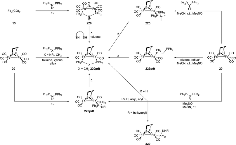 | ||
| Fig. 65 Different synthetic pathways for the incorporation of dppm and derived ligands as well as PNP ligands into hydrogenase mimics. | ||
The stable complexes Fe2(xdt)(CO)5(κ1-dppm) (223xdt) with a monodentate dppm ligand can also be isolated; in the case of pdt from the reaction of the hexacarbonyl diiron complex and dppm in acetonitrile in the presence of Me3NO. In case of adtn-propyl the reaction time has to be shortened from 60 min to 30 min. Both, the pdt and adt complexes can also be converted into to the corresponding μ-dppm compounds by thermolysis.183,326 In an attempt to synthesize the κ1-dcpm complex (224), the oxygen-sensitive ligand was partially oxidised by Me3NO at both phosphine moieties (Fig. 66).326
In addition, asymmetric κ2-chelate complexes can be synthesised if steric bulk is introduced to the backbone carbon atom as displayed by C(Me)2(PPh2)2i.e. Me2dppm. The room temperature reaction of the hexacarbonyl complex 20, Me2dppm, and Me3NO gives the κ2-chelate complex 225 in 63% yield. While in solution the apical/basal and basal/basal isomers were detected in a 2![[thin space (1/6-em)]](https://www.rsc.org/images/entities/char_2009.gif) :
:![[thin space (1/6-em)]](https://www.rsc.org/images/entities/char_2009.gif) 1 ratio by 31P-NMR, only a dibasal arrangement was observed in the crystalline form. In refluxing toluene, the chelate complex slowly rearranges to the bridged complex with a μ-Me2dppm ligand.328
1 ratio by 31P-NMR, only a dibasal arrangement was observed in the crystalline form. In refluxing toluene, the chelate complex slowly rearranges to the bridged complex with a μ-Me2dppm ligand.328
A similar ligation behaviour as observed for Me2dppm was reported for aminodiphosphine-ligands (R2P)2NR′ (PNP). The amine in the backbone of the ligand was proposed to enable a similar reactivity as the adt-amine and allowing PCET mechanisms. The thermodynamically favoured μ-PNP geometry comprising a five-membered ring is accessible by the direct reaction of the hexacarbonyl complexes with the PNP ligands in high boiling solvents, e.g. toluene or xylene.130,308,329,330 In an alternative synthesis route, Fe2(CO)6(μ-CO)(μ-PNP) (226) can be prepared photochemically from Fe2(CO)9, and subsequent reaction with the bridging dithiol.331 By this route, the first dppm complex, Fe2((μ-S)2CNR)(CO)4(μ-dppm) (227), with a bridging dithiocarbamate ligand was synthesised.332
In contrast to dppm, κ2-chelate complexes (228xdt) comprising PNP ligands can be isolated in moderate to high yields (33% to 90%). The small PNP bite angle ligands favour a dibasal geometry in solution and solid state.330,331 The substitution behaviour of PNP ligands in acetonitrile after decarbonylation with Me3NO also strongly depends on the substituent R′ on the amine. For R′ = H, the obtained chelate complex was always formed together with the bridged μ-PNP complex in a 2![[thin space (1/6-em)]](https://www.rsc.org/images/entities/char_2009.gif) :
:![[thin space (1/6-em)]](https://www.rsc.org/images/entities/char_2009.gif) 1 ratio and could not be isolated in pure form.330 PNP ligands with sterically less demanding substituents (e.g. R′ = Me, Bu, (CH2)nNMe2 (n = 2, 3), etc.) smoothly react to the desired chelate complexes (55% to 90% yield).130,330,331,333 With increasing steric bulk on nitrogen, the formation rate of the chelate complex slows down and for aryl-substituted amines often very low yields (<10% yield) were reported. Herein, the major product is the monosubstituted complex Fe2(pdt)(CO)5(κ1-PPh2NHR′) (229), in which the second P–N bond was hydrolysed.330,333,334 A more general route towards the chelate complexes is provided by irradiation of the hexacarbonyl precursor with UV light in toluene.333 The PNP chelate complexes also rearrange slowly to the thermodynamically favoured bridged isomers if solutions in toluene are heated to reflux.130,330,331
1 ratio and could not be isolated in pure form.330 PNP ligands with sterically less demanding substituents (e.g. R′ = Me, Bu, (CH2)nNMe2 (n = 2, 3), etc.) smoothly react to the desired chelate complexes (55% to 90% yield).130,330,331,333 With increasing steric bulk on nitrogen, the formation rate of the chelate complex slows down and for aryl-substituted amines often very low yields (<10% yield) were reported. Herein, the major product is the monosubstituted complex Fe2(pdt)(CO)5(κ1-PPh2NHR′) (229), in which the second P–N bond was hydrolysed.330,333,334 A more general route towards the chelate complexes is provided by irradiation of the hexacarbonyl precursor with UV light in toluene.333 The PNP chelate complexes also rearrange slowly to the thermodynamically favoured bridged isomers if solutions in toluene are heated to reflux.130,330,331
4.5.3.3 Bis(diphenylphosphino)ethane (dppe) and bis(diphenylphosphino)ethene (dppv). In contrast to dppm, the chelation of one iron centre is the most common coordination mode for dppe (Fig. 67) and its unsaturated analogue cis-bis(diphenylphosphino)ethene (dppv, Fig. 68). The formed five-membered rings are thermodynamically more favourable than the analogous four-membered rings in the case of dppm. Thereby, asymmetric complexes Fe2(xdt)(CO)4(κ2-diphosphine) are accessible. Another effect of the increased bite angle is that the basal-apical geometry of the chelate complexes becomes more favourable.335–337 The chelate complexes 230xdt (dppe) and 231xdt (dppv) form upon decarbonylation of the hexacarbonyl complexes in the presence of the phosphine ligand within hours.154,210,326,336–338 Because of its rigidity, dppv (Fig. 68) forms the chelate complexes at room temperature,154,210,326,337 while dppe (Fig. 67) requires elevated temperatures.336,338 The reported yields vary significantly in the range of 26% to 90% for dppv and 23% to 47% for dppe. The thermal reaction without Me3NO is also feasible but requires considerably extended reaction times,326 gives lower yields,326,339 or demands the use of the more electron-rich and sterically less demanding bis(dimethylphosphino)ethane (dmpe) ligand (Fig. 69).159,340,341 Upon elongated heating the κ2-dppe complexes rearrange to afford the thermodynamically even more favourable μ-dppe complexes (232xdt).342,343 For dppv the light-induced substitution of the hexacarbonyl complexes was also reported;344 however, this method is more often applied for the introduction of a second dppv ligand on the other iron centre to give the very electron-rich complexes 233xdt of high symmetry.53,154,210 Interestingly, while Fe,Fe′-disubstituted complexes [L(CO)2Fe](xdt)[Fe(CO)2(L)] (L = PR3, CN−) are unreactive towards further substitution under various conditions, additional electron donating substituents can be introduced into the complex Fe2(CO)4(edt)(κ2-dppv). Cyanide (MeCN, r.t., 234xdt), PMe3 (Me3NO, toluene, r.t., 235xdt) and the bulkier phosphines PCy3 and PiPr3 (hν) replace a carbonyl ligand on the unfunctionalised iron centre under the same conditions known for the corresponding monosubstituted complexes. The pdt analogue shows similar reactivity but the substitution processes proceeds more slowly (Fig. 68).337,345
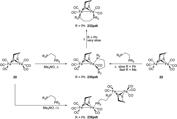 | ||
| Fig. 67 Complexes with dppe ligands comprising different binding modes and their selective synthesis. | ||
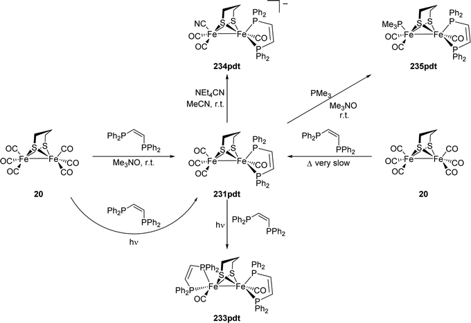 | ||
| Fig. 68 Complexes bearing dppv ligands comprising different binding modes and their selective synthesis. | ||
Dppe is also capable of linking two [2Fe–2S]-units giving “intermolecular” bridged complexes of the type [Fe2(xdt)(CO)5]2(μ-dppe) (236xdt) with half a dppe ligand per [2Fe–2S]-unit. This coordination mode is favoured if only one equivalent of dppe is added after decarbonylation with Me3NO and the reaction mixture is stirred at room temperature.145,183,339,346 In addition, this coordination mode was also observed for dmpe complexes containing the sterically crowded dithiol (Ph)2Si(CHPh(SH))2. From the reaction of the corresponding hexacarbonyl diiron complex 237 with one equivalent of dmpe predominantly the [4Fe–4S]-compound 238 is formed (Fig. 69). If two equivalents of dmpe are used, the chelate complex 239 is only a side product (7% yield) while the bridged complex Fe2((μ-SCHPh)2SiPh2)(CO)4(μ-dmpe) (240) is the main product (35% yield).159 Interestingly, complex 239 features the unusual rotated geometry, which will be discussed in Section 5.1.
Complexes of the type Fe2(xdt)(CO)4(κ2-diphosphine) can also be synthesised starting from iron(II) chloride and Fe(bda)(CO)3 (bda = benzylideneacetone) (Fig. 70, compare Section 4.4.1). Thereby, the selective labelling with Mössbauer-active 57Fe is possible. Here, iron chloride reacts with the diphosphine under one atmosphere of carbon monoxide at room temperature and (the dilithium salt of) the dithiol bridge to give the monometallic precursor.271,347 The formed Fe(xdt)(CO)2(κ2-diphosphine) complex then reacts with Fe(bda)(CO)3 as the source for the Fe(CO)3 fragment to give the asymmetric complex Fe2(xdt)(CO)4(κ2-diphosphine) (e.g.231pdt).271,348 Using 57FeCl2, the subsequent introduction of a second equivalent of dppv to afford the symmetric complex 57FeFe(pdtMe)(CO)2(κ2-dppv)2 (233pdtMe, pdtMe = 2,2-dimethyl-1,3-propanedithiol) was enabled.348 Rauchfuss and coworkers were also able to synthesize mixed-metal mimics by exchanging the Fe(CO)3 source by a Mn(CO)3 or a Co(Cp) precursor (see Section 4.4.2).271
4.5.3.4 1,1′-Bis(diphenylphosphino)ferrocene (dppf). Redox-active ferrocene ligands were used to mimic the function of the [4Fe–4S]-cluster providing electrons to the [2Fe–2S]-cluster. While the monodentate, ferrocene substituted phosphines feature the same behaviour as other monodentate phosphines,213,310,349 dppf shows coordination modes known from dppm and dppe. The connection of two [2Fe–2S]-units is common for the dppf ligand and is accessible via reaction of the hexacarbonyls with 0.5 equiv. of dppf in the presence of Me3NO at room temperature in varying yields between 24% and 90%.204,209,213,309,312,343 With toluene-3,4-dithiolate as the bridging ligand, also monodentate dppf in Fe2(bdtMe)(CO)5(κ1-dppf) (241) was observed. If 20 is refluxed in toluene in the presence of dppf for an elongated time, the “intramolecular” bridged complex Fe2(pdt)(CO)4(μ-dppf) (242) is formed.311
4.5.3.5 Other phosphines. Other bi- or tridentate phosphine ligands follow similar trends in terms of their substitution behaviour. For 1,2-bis(diphenylphosphino)benzene – as observed for dppv – the Me3NO-induced substitution is more convenient than the thermal reaction in refluxing toluene.326 The introduction of the electron-poor and thus, less reactive 4,5-bis(diphenylphosphino)-4-cyclopenten-1,3-dione with electron-withdrawing carbonyl-groups requires additional heating under refluxing conditions in toluene.314 Notably, the related compound 2,3-bis(diphenylphosphino)maleic anhydride is prone to decomposition under these conditions, but can be incorporated into the [2Fe–2S]-framework by photolysis, which is also a known alternative method for the introduction of dppv ligands.313
In accordance with the stability of five- and six-membered chelate rings, the propane-analogue of dppe, 1,3-bis(diphenylphosphino)propane (dppp) also forms chelate complexes upon CO-substitution. Under the latter conditions the complex slowly rearranges to afford the bridged μ-dppp complex.342 The 2-(n-alkyl)aza-analogues also form the expected chelate complexes as the major product in refluxing toluene together with small amounts of the intramolecular bridged complex and the tetranuclear cluster.204,350,351 The latter can be synthesised selectively by decarbonylation with Me3NO. The N-phenyl substituted phosphine gives the “intermolecular” bridged complex either with Me3NO induced decarbonylation or in refluxing toluene.351 Decarbonylation and subsequent prolonged heating in toluene allowed for the isolation of the respective chelate complex.352 The additional methylene group in the backbone of 1,3-bis(diphenylphosphino)butane (dppb) renders the formation of the chelate compound unfavourable and the “intramolecular” bridged compound is formed under both conditions. As observed for dppe, the ligands with longer carbon chains in the backbone initially form the linked [4Fe–4S]-complexes. This coordination mode can be exclusively obtained if trans-bis(diphenylphosphino)ethene is used.342 Similarly, meta-substituted pyridyl and pyrimidyl phosphines also adopt this coordination mode if 0.5 equiv. are used. In the presence of one equivalent of the phosphine ligand monosubstituted complexes Fe2(xdt)(CO)5(κ1-L) are formed.305 The tridentate phosphine bis(diphenylphosphinoethyl)phenylphosphine can be introduced in refluxing toluene and adopts a μ,κ1,κ2-coordination mode showing both features of the chelate and the bridged complexes. The constraints of this coordination mode distort the square pyramidal coordination environment around the iron centres and lead to complexes with ‘rotated state’ character.353,354
4.5.4.1 Isocyanides. Especially in the early days of [FeFe]-hydrogenase research, isocyanide ligands gained interest. With a similar Fe–C
![[triple bond, length as m-dash]](https://www.rsc.org/images/entities/char_e002.gif) N framework, but without a reactive nitrogen centre, isocyanide complexes were shown to give more stable hydrides as well as oxidised species (vide infra) as compared to the cyanides.355–357 The substitution of the carbonyl ligands (Fig. 71) occurs slowly at room temperature. However, after twenty hours to two days at room temperature the single- or double-substituted complexes can be obtained.213,355,358 For example, at 70 °C, isocyanomethane (CNMe) gives the double-substituted complex Fe2(pdt)(CO)4(CNMe)2 (243) after two hours in acetonitrile.356 Prolonged heating gives the three- and four-times substituted complexes (244 and 245) (Fig. 71).356,357 If Me3NO is applied, the double-substituted complex is also accessible selectively at room temperature within hours.213,283 Notably, 1,4-diisocyanobenzene was also highlighted to enable bridging of two [2Fe–2S]-subunits (246).204,213
N framework, but without a reactive nitrogen centre, isocyanide complexes were shown to give more stable hydrides as well as oxidised species (vide infra) as compared to the cyanides.355–357 The substitution of the carbonyl ligands (Fig. 71) occurs slowly at room temperature. However, after twenty hours to two days at room temperature the single- or double-substituted complexes can be obtained.213,355,358 For example, at 70 °C, isocyanomethane (CNMe) gives the double-substituted complex Fe2(pdt)(CO)4(CNMe)2 (243) after two hours in acetonitrile.356 Prolonged heating gives the three- and four-times substituted complexes (244 and 245) (Fig. 71).356,357 If Me3NO is applied, the double-substituted complex is also accessible selectively at room temperature within hours.213,283 Notably, 1,4-diisocyanobenzene was also highlighted to enable bridging of two [2Fe–2S]-subunits (246).204,213
4.5.4.2 N-heterocyclic carbenes (NHCs). Like phosphines, N-heterocyclic carbenes (NHCs) are strong σ-donor ligands with tuneable steric properties. Their similar donor strength, stability of the corresponding complexes as well as their more convenient handling, e.g. compared to PMe3, raised the interest in exchanging phosphine ligands by NHCs.359,360 Accordingly, NHCs were also applied for the generation of electron-rich (mono)substituted active site mimics. The substitution of the carbonyl ligands by NHCs in the hexacarbonyl complexes occurs at room or moderately elevated temperatures (up to 60 °C) (Fig. 72). The sterically less demanding ligand 1,3-dimethylimidazol-2-ylidene (IMe) solely forms the monosubstituted complex at room temperature in high yields (83% for pdt),361 while at 60 °C the disubstituted complex Fe2(pdt)(CO)4(IMe)2 (247) is preferably formed (50% yield compared to 12% of the monosubstituted complex).291 With sterically more demanding NHCs (e.g. 1,3-dimesitylimidazol-2-ylidene (IMes)) only the monosubstituted complex 248 is observed in high yields (>70%).181,362–364 Under reflux conditions in toluene, PMe3 can be introduced into the monosubstituted complexes on the Fe(CO)3 fragment to give very electron-rich asymmetric mimic Fe2(pdt)(CO)4(IMes)(PMe3) (249, Fig. 72).361,365 The substituents at the nitrogen atoms have also been functionalised with additional donor groups. While thioethers and amines were shown not to coordinate the iron atom even in the presence of Me3NO,363 the pyridine nitrogen in 1-methyl-3-(pyridylmethyl)-imidazol-2-ylidene binds to the iron centre immediately (250).364 Interestingly, if the symmetric, N,N′-disubstituted 1,3-bis(pyridylmethyl)-imidazol-2-ylidene ligand is used, only the carbonic carbon atom and none of the pyridines coordinates to the iron centre in 251 at room temperature and even at 60 °C only 20% yield of complex 252 with a κ2-NHC ligand was obtained. However, one of the pyridine nitrogen atoms can be coordinated upon addition of Me3NO to the monodentate complex. By this method the κ2-complex is obtained in 90% yield. The coordination of the other pyridine moiety or a ligation of the second iron atom are not observed.364 Similar to bidentate phosphines, bis-carbene ligands with different alkyl linkers were introduced. With these ligands monosubstituted complexes, chelate complexes (253), intermolecular bridged complexes (254) and mixtures thereof were obtained in low to moderate yields (up to 50%).181,363
Like mono-substituted phosphine complexes, NHC complexes are reasonably stable under ambient conditions even in solution. Carrying an additional phosphine ligand, the stability of the complexes towards air is massively reduced in solution, however the solids can be handled under air.361
4.5.4.3 Thioethers and sulfoxides. In contrast to cyanides and carbonyls, the third ligand observed in the active site – (metallo-)thioethers – gained considerably less interest as discrete ligands. However, thioethers and sulfoxides can also be introduced as terminal ligands by decarbonylation with Me3NO and subsequent addition of the ligand at room temperature (255, Fig. 73).366–368 In an alternative route, thioethers can be incorporated after one of the carbonyl ligands is converted to a Fischer-type carbene (256b) with n-BuLi and [Et3O]BF4.367 The organometallic equivalent of a thioether Cp(CO)2FeSPh or Cp(CO)2Fe(Cys-κS), mimicking the native cysteine link to the [4Fe–4S]-cluster, can also be incorporated by the former method.178,204,209 The chemistry of [2Fe–3S]-assemblies is also part of Section V.
4.5.4.4 Amines and pyridines. By heating Fe2(pdt)(CO)6 to reflux in propylamine, the complex Fe2(pdt)(CO)5(NH2Pr) was obtained. This complex was shown to be stable in non-coordinating solvents. However, in coordinating solvents, e.g. acetonitrile, the amine ligand is replaced by the solvent molecule.369 In contrast, complexes with pyridine donors and derivatives were found to be stable. The substitution with pyridine proceeds via decarbonylation with Me3NO,370 while the chelating ligands 2,2′-bipyridine371 and 1,10-phenantroline372 were introduced in refluxing toluene. The incorporation of an additional PMe3 substituent was also shown to be feasible with Me3NO for the latter one.373 Adding two additional thiolate functions to 2,2′-bipyridine e.g. in 2,2′-([2,2′-bipyridine]-6,6′-diyl)bis(1,1-diphenylethane-1-thiolate) (= LN2S2) yields the chelate complex 257 (Fig. 74) after adding NiCl2 in THF at room temperature. Interestingly, changing the metal from nickel to iron, e.g. Fe(BF4)2, yields [Fe2(LN2S2)2H]+ (258), a dimeric structure in which one thiolate is protonated.374 Both complexes can be reacted with [CpFe(CO)(MeCN)2]+ yielding the respective NiFe- and FeFe-complexes (259 and 260).375,376 Thus, the LN2S2 ligand closes the gap between [FeFe]- and [NiFe]-hydrogenase models, enabling both types of metal content.
4.6 Towards structural and functional H cluster models
The rich chemistry of Fe2(SR)2(CO)6−nLn complexes, some of which developed almost a century ago, enabled the preparation of diverse synthetic mimics of the [2Fe]H-cluster. The first and most simple model complexes bearing a dithiolate bridge were synthesised decades before the crystal structure was known. Based on the knowledge gained out of these studies, a variety of more accurate active site mimics were reported after the determination of the crystal structure. At first, the efforts focused on an exact representation of the ligands on the iron centre and the incorporation of different bridgehead atoms. Aiming at both structural and functional mimics, more complex alterations of the active site were pursued. By now, numerous protocols for the incorporation of different (functionalised) dithiolate bridges as well as many classical organometallic ligands and a combination thereof are available. The Fe(CO)3 platform enables versatile ligand substitutions by associative or after thermal, photochemical or chemical decarbonylation by dissociative pathways. Both, functionalised ligands and bridges can be used to achieve the desired electronic or structural properties of the mimic and allow for the attachment of photosensitizers, redox active groups, or proteins. Much of the progress, in the development of synthetic protocols was driven by the aim to understand the relationship of structure and function of the [2Fe]H-cluster. The most prominent example in this regard is the amine in the dithiolate bridge. Even before its presence in the active site was confirmed, the proposed function as a proton relay was confirmed in e.g. protonation experiments and gave strong evidence for its utmost importance. In the next sections, we will present how the synthetic progress gave rise to complexes that were able to mimic almost all relevant features (e.g. rotated structure, CO-binding, protonation behaviour, proton reduction, hydrogen oxidation, etc.) observed in the protein. Although there is no mimic known that is alone capable to display all properties of the natural active site, the variety of model complexes together is able to cover all aspects of [FeFe]-hydrogenases’ activity.V Structural models of the active site
In this section, we will present how by combination of different ligands and dithiolate bridges sophisticated structural or functional models of the active site were designed.5.1 H-cluster models mimicking the rotated state
The distal iron atom in the native H-cluster features an unusual coordination environment, which is referred to as the ‘rotated state’. Namely, the square pyramidal geometry is inverted compared to the hexacarbonyl and dicyanide complexes. One of the formerly terminal carbonyl ligands subsequently adopts a semi-bridging position. This unusual geometry is not found in the hexacarbonyl complexes, in which the carbonyl ligands of the two iron centres are eclipsed and many of the reported, substituted model complexes show the same unrotated geometry. However, due to steric interactions or other constraints deviations from the idealised, eclipsed geometry were observed. Aiming at structural models of different enzyme states, more elucidated models featuring the special rotated geometry were developed and will be presented herein.Already in 2003 Bruschi, Fantucci, and De Gioia377 presented a DFT study on FeIFeI complexes, which proposed stable energetic minima corresponding to a rotated state. In 2006, Tye, Darensbourg, and Hall378 then investigated the influence of various substitution patterns on the stability of rotated structures with DFT calculations and showed that these structures become more favourable when altering the electron donating ligands (e.g. phosphines) from Fe,Fe′- to Fe,Fe-disubstituted complexes. In accordance with earlier reports on oxidised and reduced species with bridging carbonyl ligands,357,379,380 the calculations also affirmed the increased stability of the rotated structures upon oxidation/reduction. In addition, it was proposed that strongly electron donating ligands on one iron atom in combination with strongly electron accepting ligands on the adjacent iron centre is another promising strategy towards “rotated models” – a strategy which is brought to an extreme by the use of NO+ ligands in synthesis.381–383 With one exception, in which one carbonyl ligand is forced into a bridging position by binding to strong Lewis acids,53 at least one of these three strategies, is found in every active site mimic featuring a rotated geometry.
 | (1) |
In a square pyramidal environment, the four involved bonds span a basal plane. Accordingly, both angles equal 180° giving τ = 0. In reality, for unrotated as well as rotated complexes, the iron atom is distorted out of the basal plane towards the apical ligand, so that both angles adopt values smaller than 180°, e.g. 156° and 160°, in the case of the pdt hexacarbonyl complex.288 Still, in a symmetrical coordination environment τ is almost equal to zero. If the ligands around the iron form a trigonal bipyramid, a carbonyl ligand and a thiolate are in axial positions, while the other two ligands span the trigonal plane together with the third carbonyl ligand. This arrangement corresponds to an angle of 180° between the axial bonds, respectively 120° between the equatorial bonds. Hence, in trigonal bipyramidal environments τ = 1. However, values of τ = 1 are not observed in real structures for two reasons, which will be explained at the example of Fe(pdtEt)(CO)4(PMe3)2 (261, pdtEt = 2,2-diethyl-1,3-propanedithiolate, Fig. 76).382 In this complex, the coordination environment of one iron centre can be described as trigonal bipyramidal. The iron, one of the sulphur atoms and both carbonyl atoms span the equatorial plane with only small deviations. Still, the angles between the ligands at the iron centre do not all equal 120°. The two S–Fe–C angles have values of 128° and 129° and the angle between the carbonyl ligand equals 102°, which is at the upper end observed for such complexes. Accordingly, in none of the severely distorted complexes reported in literature the largest angle in this plane ∡(S1–Fed–C1) is smaller than 127°.381 In addition, the axial ligands almost never adopt positions, in which the angle ∡(S2–Fed–C2) between them is 180°, i.e. because of the constraint S–Fe–S angle. Typical values are 167° to 170°, 169° in the case of 261, with various examples below this range and only two examples159,382 above a value of 173°, both of which with smaller τ values (0.48 and 0.17) and sterically crowded dithiolates. Due to these deviations from an idealised trigonal bipyramidal environment Addison's τ-parameter is always considerably smaller than τ = 1. For 261, a value of τ = 0.67 is obtained and with the limits of ∡(S1–Fed–C1) = 127° and ∡(S2–Fed–C2) = 173° described above an estimated maximal value of τ = 0.77 can be extrapolated. Considering this behavior, complexes for which τ is about 0.75 can be considered trigonal bipyramidal and represent the transition from an unrotated to a rotated geometry. This upper limit should be considered when using Addisons’ τ parameter to quantify the rotation of the iron centre. Moreover, the value is influenced by the position of four out of five ligands and therefore, sensitive to small changes in their position, e.g. due to steric effects, which can complicate the comparison of different complexes.
 | ||
| Fig. 76 Molecular structure of complex 261. CCDC ID: PEGCOV.382 | ||
As a second aspect, the torsion angles between the apical ligand on the unrotated iron centre and the ligands on the rotated iron centre can be evaluated. Especially, the largest – including the (semi-bridging) carbonyl – and the smallest angle that can be regarded as the distortion of the eclipsed unrotated complex are of interest. Being the most intuitive values, care must be taken as the apical ligand on the unrotated iron can also be distorted from its idealised position (up to 20°) most often due to steric repulsion with the dithiolate bridge. In this context, 261 is again a useful example. Torsion angles of 75° (regarding C1) and 176° (regarding Cb) are observed indicating a fully rotated complex. However, the apical ligand on the less distorted iron centre does not lie symmetrically between both sulphur atoms. If instead of the apical ligand, the pdt bridgehead carbon, which adopts an almost symmetric position, is used for the calculation, more realistic torsion angles of 56°, respectively 157° are obtained. Even though the idealised torsion angles are useful quantifiers for the rotation of the iron centre, the described distortion can render these values meaningless, without careful evaluation of the complete complex.
The third aspect is the (semi-)bridging character of the “inverted” carbonyl ligand. The four relevant structural values discussed in the literature to distinguish between terminal, semi-bridging and bridging carbonyls are the Fep–Fed–Cb angle Ψ, the Fed–Cb–Ob angle Θ and both Fe–Cb distances. Crabtree and Lavin384 examined the correlation between these structural parameters in (semi-)bridging carbonyl ligands of different iron carbonyl complexes. In this discussion, structural parameters of different classes of iron carbonyl ligands were used, and even though, all of the complexes herein belong to a single class in different oxidation states, with different ligands, and different steric strain these values and their correlations are astonishingly valid. For terminal carbonyl ligands Ψ is about 100° in hexacarbonyl complexes and substituted complexes without steric bulk, e.g. Fe2(pdt)(CO)4L2 (L = CO, CN−, PMe3).277,279,288 If carbonyl ligands adopt positions with a higher bridging character, this value decreases. While for semi-bridging carbonyls this decrease correlates linearly with a decrease of Θ, in the case of terminal carbonyls, uncorrelated values of Θ > 170° corresponding to almost linear carbonyl ligands are observed. Based on the extrapolation of Ψ for which Θ = 180°, Crabtree and Lavin suggested Ψ = 75° as the frontier between terminal and semi-bridging carbonyl ligands. Even though Θ is not smaller than for terminal carbonyl ligands for Ψ values between 70° and 75°, there is a distinct difference between these ligands. While for values Ψ < 75° the oxygen atom is bent away from Fe2 corresponding to semi-bridging carbonyls, the orientation of the ligands is governed by steric effects for increased values. For Ψ = 75° a distance Fep–Cb of 2.69 Å was extrapolated, almost in the middle between the sum of the covalent radii (1.94 Å) and the sum of the van der Waals radii (ca. 3.5 Å). Accordingly, this distance is also a useful criterion for the evaluation of the bridging character. The length of the actual M–CO bond can also be considered. Below an angle Ψ of 70°, the bonds are lengthened due to a diminished π-backbond and correspond to a regular single bond in the symmetrically bridging case. As described above, the π-backbond strengthens and the M–CO bond shortens upon binding of electron rich ligands. The different bond lengths have to be considered, when comparing different complexes, which makes the other values Ψ, Θ, and Fep–Cb more robust in the context of this evaluation.
In Fig. 78, the values Ψ and τ of the nitrosyl substituted complexes [Fe2(xdt)(CO)4−n(PMe3)1+n(NO)]+ (xdt = edt, pdt) (Fig. 77) are plotted. The unrotated complex 262edt is characterised by a low τ value and a large angle Ψ. With increasing degree of rotation, Ψ decreases while τ increases initially. The strongly distorted molecule 263edt and the rotamer 263pdt.1 are characterised by high τ values and angles Ψ at the edge of terminal to semi-bridging carbonyls. Both values decrease hereafter to characterise the rotamer 263pdt.2 with a rotated structure.
As an additional aspect in this regard, the carbonyl IR stretching frequencies are useful to evaluate their bridging character especially if no crystal structure is available. Similar to the M–CO bond length, the frequencies are also sensitive to the electron-donating abilities of other ligands, as well as oxidation states of the iron centres and accordingly, have to be assessed carefully. Still, in comparison of similar compounds carbonyl stretching frequencies and Ψ match well. More importantly, the observation of the band of the semi-bridging CO ligand by IR spectroscopy provides an easy, but powerful tool to assess the structure of the complexes in solution, which can differ strongly from the solid state (vide infra). Table 6 summarises various structural and spectroscopic parameters of complexes featuring a rotated or distorted geometry.
| Complex | Dithiolate | Ox. State | Ligands | Ψ/° | Θ/° | τ | Bond length | μ-CO ν/cm−1 | CCDC ID | Ref. | ||
|---|---|---|---|---|---|---|---|---|---|---|---|---|
| Fed/Fep | Fed | Fep | Fed–Cb | Fep–Cb | ||||||||
| ′ second molecule in asymmetric unit, .1/.2 are rotamers.a Only observed in solid state.b Not all crystallographic data are reported.c Geometric and electronic situation is different in solution.d Disordered, values given for the stronger rotated molecule.e Second molecule in the asymmetric unit with negligible structural deviations.f Regarding the non-innocent NO-ligand other assignments are also reasonable. | ||||||||||||
| 265 | adtBn | I/I | dmpe | 57 | 146 | 0.12 | 1.815 | 2.179 | 1777a | YIJDEC | 341 | |
| 266 | pdtEt | I/I | dppv | 65 | 158 | 1.744 | 2.499 | 1818a | 344 | |||
| 239 | Ph2Si(C(Ph)HS−)2 | I/I | dmpe | 64 | 156 | 0.48 | 1.789 | 2.379 | 1801a | KOYKAM | 159 | |
| 235edt+ | edt | I/II | dppv | PMe3 | 72 | 170 | 0.00 | 1.781 | 2.628 | 1883 | XIGFEZ | 386 |
| 235pdt+ | pdt | I/II | dppv | PMe3 | 73 | 170 | 0.00 | 1.786 | 2.678 | 1889 | AGEHIE | 345 |
| 268PiPr3+ | pdt | I/IIc | dppv | PiPr3 | 79 | 178 | 0.00 | 1.785 | 2.833 | 1870c | AGEHOK | 345 |
| 249+ | pdt | I/II | IMes | PMe3 | 57 | 152 | 0.20 | 1.864 | 2.196 | 1861 | LIHCAH | 365 |
| 270+d | pdtMe | I/II | PMe3 | PMe3 | 58 | 152 | 0.03 | 1.813 | 2.204 | 1859 | NONFEC | 387 |
| 261+ | pdtEt | I/II | PMe3 | PMe3 | 58 | 153/146 | 0.17 | 1.839 | 2.222 | 1874 | PEGCUB | 382 |
| 233pdt+ | pdt | I/II | dppv | dppv | 71 | 170 | 0.05 | 1.786 | 2.618 | 1884 | RIXQAS | 388 |
233pdtMe+![[thin space (1/6-em)]](https://www.rsc.org/images/entities/char_2009.gif) e e |
pdtMe | I/II | dppv | dppv | 65 | 163 | 0.00 | 1.793 | 2.460 | 1.854 | HELPOG | 348 |
| 271+ | adtBn | I/II | dppn | 68 | 167 | 0.10 | 1.769 | 2.516 | 1896 | AVUSAM | 389 | |
| 278 | SCR− | I/IIf | NO, PPh3 | 70 | 168 | 0.08 | 1.783 | 2.570 | 1875a | GICRUF | 390 | |
| 262edt | edt | I/IIf | NO, PMe3 | 91 | 177 | 0.25 | 1.821 | 3.170 | NOJVUE | 381 | ||
| 262edt′ | edt | I/IIf | NO, PMe3 | 91 | 179 | 0.28 | 1.827 | 3.162 | NOJVUE | 381 | ||
| 263edt | edt | I/IIf | NO, PMe3 | PMe3 | 81 | 173 | 0.62 | 1.792 | 2.872 | NOJWEP | 381 | |
| 263pdt.1 | pdt | I/IIf | NO, PMe3 | PMe3 | 76 | 172 | 0.67 | 1.794 | 2.479 | NOJWIT | 381 | |
| 263pdt.2d | pdt | I/IIf | NO, PMe3 | PMe3 | 66 | 160 | 0.52 | 1.813 | 2.472 | NOJVOY | 381 | |
| 263pdt.2′d | pdt | I/IIf | NO, PMe3 | PMe3 | 62 | 154 | 0.38 | 1.780 | 2.325 | NOJVOY | 381 | |
| 280 | pdt | I/IIf | NO, IMes | PMe3 | 51 | 136 | 0.12 | 1.747 | 2.028 | UGOGUU | 383 | |
| 263pdtMe | pdtMe | I/IIf | NO, PMe3 | PMe3 | 58 | 148 | 0.30 | 1.802 | 2.182 | 1877 | PEGDEM | 382 |
| 263pdtEt | pdtEt | I/IIf | NO, PMe3 | PMe3 | 59 | 153 | 0.35 | 1.797 | 2.234 | 1874 | PEGDAI | 382 |
| 261 | pdtEt | I/I | PMe3 | PMe3 | 82 | 172 | 0.67 | 1.747 | 2.873 | 1899 | PEGCOV | 382 |
This effect that is caused by steric repulsion between the bridge and the apical ligand is also an integral part of other rotated FeIFeI models. Moreover, all complexes feature, as proposed by Tye, Darensbourg and Hall, an asymmetric ligand environment on the [2Fe–2S]-core, rendering one iron atom strongly electron-rich due to two donating phosphine ligands. The very similar complexes 265341 and 266,344 reported in 2013, were the first rotated FeIFeI complexes characterised by X-ray crystallography (Fig. 79). Both complexes feature an additional stabilisation of the free coordination site on the rotated iron site through an agostic interaction. This interaction, although being weak, was identified by DFT calculations as crucial feature for obtaining the rotated geometry in the crystalline state. Notably, the asymmetric unit of the crystals of 266 feature two independent molecules one of which is rotated while the other is unrotated. This indicates a small energy difference between both confirmations. Likewise, it suggests that packing effects in the crystal also play an important role for stabilising the rotated conformation.
The coordination geometry of complex 239159 with a sterically heavily crowded dithiolate ligand shows a distorted, inverted square pyramidal geometry in the molecular structure. Nevertheless, the coordination environment also has a considerable trigonal bipyramidal character (τ = 0.48). The Fe(CO)3 unit is rotated out of an idealised square pyramidal environment by about 10°–15°. The authors denoted this geometry as semi-rotated and concluded that the missing agostic interaction, compared to 265 and 239, prevents full rotation. By examination of other geometric parameters, a different conclusion can be proposed. One of the carbonyl ligands has considerable semi-bridging character (Ψ = 64°, Θ = 156°, Fep–Cb = 2.379 Å), less than in 265 but slightly higher than in 266. In addition, the angle ∡(S1–Fed–C1), which is used for the calculation of τ, is unusually large. The value of 175° is at least 5° larger than usual for rotated as well as unrotated complexes leading to an unusual linear arrangement, which could be caused by the high steric strain. Assuming a typical value of 170° for this angle, τ would equal 0.4 in accordance with a less distorted complex. Regarding the positions of C1O and the phenyl group, that shields the open coordination site, in the crystal (Fig. 80) the distortion may be attributed to steric repulsion between the two groups. Accordingly, it can be proposed that the complex is a fully rotated complex that is distorted due to steric strain. Due to the low number of comparable complexes and the small energy differences in the DFT calculations regarding this complex this explanation was not investigated further.
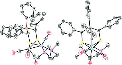 | ||
| Fig. 80 Molecular structure of complex 239 featuring a rotated geometry. CCDC ID: KOYKAM.159 | ||
Even though all three complexes 239, 265 and 266 were crystallised in the rotated state and μ-CO bands were detected in the IR spectra of the solids, the solution IR spectra show no bands for bridging carbonyl ligands. Accordingly, for none of the three complexes the rotated geometry is preserved in solution. Rotated complexes in solution were, except from 264xdt, only observed for oxidised or NO+-bound complexes. A very important feature of the three complexes 239, 265 and 266 is that in each complex the Fe(CO)3 unit is rotated. This is in accordance with the calculations of Tye, Darensbourg and Hall,378 but no mimic in other oxidation states with a rotated Fe(CO)3 unit has been crystallised.
These four examples indicate that for FeIFeI complexes a rotated geometry can be obtained by following the following strategies:
(1) Destabilisation of the apical ligand through steric bulk on the dithiolate.
(2) Stabilisation of the bridging carbonyl ligand.
(3) Stabilisation of the vacant coordination site through weak intramolecular interactions.
(4) Introduction of an electronic asymmetry on the two iron centres.
5.1.3.1 FeIFeII Hox-models. Since the structure of the active Hox state was identified, dedicated efforts in modelling its key feature – the rotated geometry – were invested. The formation of a bridging CO ligand in FeIFeII Hox-models was first reported for the very same system as for the FeIFeI-complexes by Best, Pickett and their coworkers in 2002. In situ IR measurements of (electro-)chemically oxidized [Fe2(pdtMeSMe)(CO)4(CN)2]2− (267) revealed a μ-CO band (see Section 5.2).379 In 2007, the groups of Rauchfuss386 and Darensbourg365 independently presented the mixed valent FeIFeII complexes 235edt+ and 249+ showing a rotated geometry (Fig. 81). Both complexes were prepared by oxidation of asymmetrically substituted, not rotated model complexes with ferrocenium in non-coordinating solvents and isolated as their [BF4]−, respectively [PF6]− salts. A crucial feature of both complexes is a sterically demanding and strongly electron donating ligand on the rotated iron atom. While Rauchfuss and coworkers applied a dppv ligand on the rotated iron centre, Liu and Darensbourg installed an IMes ligand. In both cases, the unrotated iron atom is substituted with a PMe3 ligand, which stabilises the oxidised FeII centre. In these complexes, the rotated geometry is not only present in the solid state, as observed for the rotated FeIFeI models, but also can be detected in solution, as indicated by bands for (semi-)bridging CO ligands in the IR spectra. Complexes with other dithiolates 235xdt+ (pdt, adt, adtBn, odt)391 and phosphines [Fe2(pdt)(CO)3(κ2-dppv)(PR3)]+ (268PR3+, PR3 = PCy3, PiPr3)345 were also reported by Rauchfuss later on. The exchange of PMe3 by dppv also afforded rotated complexes 233pdtR+ with pdt388,392 and pdtMe bridges.348 By using the redox active phosphine PEt2Fc* instead of PMe3, Camara and Rauchfuss presented elaborate, functional model complexes 269adtR+ with adtR bridges (R = Bn, H). The IR spectra of these complexes also indicate a rotated complex geometry.349 In addition, Darensbourg and coworkers reported that less bulky NHCs lead to less stable complexes that could not be characterised by X-ray diffraction. The bands assigned to μ-CO are strongly blue-shifted by 68 cm−1 compared to 249+ in the solution IR spectra of these complexes and indicate a greatly reduced or no semi-bridging character of the carbonyl ligand. Thus, steric bulk was identified as a key feature of rotated complexes.361 Interestingly, it could be shown that the introduction of steric bulk on the dithiolate bridge (pdtMe and pdtEt) allows for rotated complexes 270+ and 261+ even with two small PMe3 ligands. The authors highlighted that, in contrast to 249+ and 270+, the higher thermal stability of 261+ allows for room temperature EPR measurements.382,387 Rauchfuss and coworkers reported later that the limited thermal stability of their compounds can be avoided by using [BArF4]− instead of [BF4]− as the counterion.393 The corresponding complexes showed no decomposition in solution at room temperature for days. The instability of the [BF4]− anion towards electrophilic iron complexes has been reported earlier – interestingly also in the context of complexes for hydrogen activation/generation.394
Without doubt, all these complexes can be regarded as rotated state mimics (τ, torsion angles, crystal structure). Upon closer inspection of the structural features, some distinct differences are obvious. While the models with the NHC ligand and the bulky bridges all show carbonyl ligands with a high semi-bridging character (Ψ < 60°), in the dppv substituted complexes the carbonyl ligands are on the edge between terminal and semi-bridging (Ψ = 71°–79°). Only in the complex with the bulky pdtMe bridge, the carbonyl ligand has considerably higher semi-bridging character (Ψ = 65°) attributed to the steric repulsion between dppv and the dithiolate. Remarkable in this regard is also the structure of complex 268PiPr3+, as the low-energy μ-CO band (1870 cm−1) in the solution IR spectrum indicates a higher bridging character of the semi-bridging carbonyl ligand but the opposite is found in the crystal (Ψ = 79°).
Supported by additional DFT calculations,382,387,395 in most complexes the iron centres were accordingly attributed the oxidation states FeIIpFeId.345,361,382,387 This is especially interesting, as the same assignment is assumed in the active Hox state (see Section 3.2). The EPR measurements of the PiPr3 and PCy3 substituted complexes 268PiPr3+ and 268PiCy3+ indicate another assignment despite the similar crystal structure of 268PiPr3+ compared to complexes 235edt+ and 235pdt+.345 While for all other complexes the spin (S = 1/2) is mainly localised on the rotated iron centre, and in some cases partially on the dithiolate,382 in the complexes substituted with bulky phosphines 31P hyperfine coupling constants indicate that the spin is localised on the other iron centre. Comparing the solution IR spectra to spectra of a rapidly precipitated solid and grown single crystals, in the latter of which no μ-CO band is detected. The authors concluded that in solution the other iron centre Fe(CO)2(PR3) is rotated exhibiting a stronger semi-bridging carbonyl ligand. In this case, the spin resides on the rotated iron centre also in solution.
In order to synthesise a more electrophilic Hox-model for hydrogen oxidation experiments, Camara and Rauchfuss389 synthesised the tetracarbonyl complex Fe2(adtBn)(CO)4(κ2-dppn) 271 (dppn = 1,8-bis(diphenylphosphino)naphthalene). Its cation 271+ is, in contrast to other adt tetracarbonyl cations, stable at room temperature in solution for at least 24 h. Its structure, the first crystallographically confirmed of a rotated adt complex, is very similar to the dppv complexes reported by Rauchfuss with a higher semi-bridging character (Ψ = 68°) of the carbonyl ligand on the rotated Fe(μ-CO)(dppn) unit. The complexes Fe2(xdt)(CO)4(κ2-L)+ (272xdt+, xdt = adtBn, edt, pdt, bdt3Me; L = nPrN(CH2PPh2)2) also feature the rotated geometry and an enzyme-like proton relay.396,397 These complexes resemble the only examples of rotated [FeFe]-hydrogenase mimics, in which the unrotated iron centre is unsubstituted. By EPR measurements, the same FeIIpFeId electronic structure was identified.
If the oxidation of the electron-rich precursors is conducted in coordinating solvents, e.g. acetonitrile, the coordination of a solvent molecule promotes the oxidation to the diferrous complexes.337,345,386,398 Likewise, in the presence of phosphines,398–400 cyanides,399 isocyanides,356,357 or even the adt amine391,401 oxidation to the FeIIFeII complexes occurs. A bridging carbonyl ligand is a prominent feature of many of the obtained complexes. Moreover, the diferrous complexes are labile towards further substitution to give highly substituted complexes. An overview over these oxidatively induced ligand substitutions is given in Fig. 83.
5.1.3.2 Hydrogen oxidation by Hox-models. Despite the high activity of [FeFe]-hydrogenases for the dihydrogen oxidation,402,403 the application of mimics as proton reduction catalysts always dominated research and dihydrogen activation is rare with mimics. Still, H/D exchange reactions catalysed by bridging hydride complexes indicated heterolytic dihydrogen activation.277,278,355,404 The photolytic oxidative addition of dihydrogen to Ru2(pdt)(CO)4(PCy3)2 (198) reported in 2004, gave the dihydride complex HRu2(pdt)(μ-H)(CO)3(PCy3)2. In the presence of coordinating solvents or counterions hydrogen is released upon protonation, while in CH2Cl2 with [H(OEt2)][BArF4] (ArF = 3,5-bis(trifluoromethyl)phenyl) a dihydrogen σ-complex is formed.270 For the iron complex 231edt, the photolytic oxidative addition to a similar dihydride complex was also reported. In the presence of B(C6F5)3 heterolytic dihydrogen activation yields a complex bearing a bridging hydride.405 The ruthenium and the iron complexes are both capable of oxidatively adding other E–H (E = Cl, O, S, Si) bonds.
The first, actual biomimetic dihydrogen activation was reported for the rotated Hox-models 235adtR+ [Fe2(adtR)(CO)3(PMe3)(κ2-dppv)][BArF4] (R = H, Bn) (Fig. 82).393 The corresponding pdt and odt complexes are incapable of performing this reaction, again highlighting the importance of the internal proton shuttle for any hydrogenase-like activity. However, the reaction was reported to be slow and required high H2 pressures (12.4 MPa). In the presence of additional oxidants (e.g. substituted ferrocenium) the reaction rate is strongly increased.389 This observation was explained with the mechanism shown in Fig. 84. Similar to a PCET, the heterolytic cleavage of dihydrogen is proposed to occur simultaneously to the oxidation of the complex by the additional oxidant, which is incapable of oxidising 235adtR+. Without ferrocenium present in solution a second molecule of 235adtR+ is oxidised, which limits the reaction rate. The rate limiting step in the presence of an oxidant is the binding of H2 to the open coordination site. The formed, but not observed double-protonated intermediate is then most likely deprotonated, either by an additional base e.g. P(o-tolyl)3 or by reduced 235adtR+, yielding the bridging hydride. At some point during the mechanism, the formed terminal hydride isomerizes to a bridged hydride. Thus, in the absence of additional oxidants and bases only half of the bridging hydride is directly formed from the heterolytic dihydrogen cleavage, while the other half is formed by reduction and subsequent protonation. Contrary, in the presence of excess oxidant and base, more realistic for the situation in the enzyme, the bridging hydride is formed quantitatively from heterolytic H2 activation. The more electrophilic complex 271+ shows an even higher reaction rate. Still, both complexes do not show any catalytic activity, which is attributed to the fact that deprotonation of the bridging hydride is not feasible. Indeed, complexes 272xdt+, in which deprotonation of the bridging hydride is easily accessible, shows catalytic hydrogen oxidation activity.396 For this complex, also the double-protonated intermediate is observed. Other models that show catalytic activity, though at low turnover numbers, are complexes 269adtBn+ and 269adt+.349 Here, the internal oxidant not only increases the rate of H2 activation compared to 235adtR+, but increases the acidity of the bridging hydride upon oxidation. This allows for the deprotonation required for catalytic H2 oxidation.
Subsequently, Hogarth, Holt and coworkers reported on the electrochemical H2-oxidation catalysed by Fe2(pdt)(CO)4(dppf) also featuring an internal oxidant in the presence of base. However, the mechanism in the absence of an internal proton shuttle remained unclear and the authors tentatively suggested an intermediary dihydride species.311
5.1.3.3 Nitrosyl substituted Hox-models. Binuclear, nitrosyl substituted iron sulphur complexes are known for more than 150 years. In 1858, Roussin reported on the “red salt” K2[Fe2S2(NO)4] and the corresponding “ester” Fe2(SR)2(NO)4.406,407 Interestingly, the first rotated diiron nitrosyl complex [Fe2(μ,η2-SCR)(CO)4(NO)(PPh)3] (278) was already reported in 1988 by Behrens and coworkers (Fig. 85). In this complex, the iron centres are bridged by a thioacyl moiety and a semi-bridging carbonyl ligand, which is not observed in the absence of the phosphine.390 Nitrosyl substituted hydrogenase mimics were firstly reported in 2008 by the groups of De Gioia and Rauchfuss.381 Also in this first report, the authors showed that the substitution of carbonyl by nitrosyl ligands can lead to rotated complexes. Since assigning (formal) oxidation states in the presence of nitrosyl ligands can be difficult (NO+vs. NO˙), complexes with nitrosyl ligands are discussed separately.
 | ||
| Fig. 85 Exemplary nitrosyl substituted complexes. Note: in the crystalline state 263pdt shows different degrees of rotation. | ||
Generally, NO+ used as the [BF4]− salt replaces a carbonyl ligand within several hours at room temperature or even 0 °C. The reaction is limited by the poor solubility of NOBF4 in CH2Cl2, which is used to decrease the rate of decomposition of the products. The diamagnetic nitrosyl complexes are air-sensitive and temperature labile, but sufficiently stable at 0 °C.381–383,408 Handling and storing the complexes under an atmosphere of CO was also reported to increase the stability of the complexes.383 In literature, only nitrosyl complexes of electron-rich mimics are known. Not surprisingly, several studies showed that the nitrosyl cation attacks at the more electron-rich iron atom. Further substitution reactions with electron donating ligands (PMe3, CN−) were shown to occur on the nitroso substituted iron centre.381,383 Apart from the very electron rich Fe2(pdt)(CO)2(κ2-dppv)2 (233pdt), only monosubstituted nitrosyl derivatives are reported. Induced by the steric repulsion of the two dppv ligands, [Fe2(pdt)(CO)(κ2-dppv)2(NO)]+ (279pdt) is also unusual as the NO+ ligand adopts a basal site, whereas it is usually apical in unrotated complexes.408
Nitrosyl complexes gained interest after the first report of a rotated complex bearing a nitrosyl ligand. [Fe2(pdt)(CO)3(PMe3)2(NO)]+263pdt was shown to crystallise as an apical and a basal rotamer referred to the PMe3 on the Fe(CO)2(PMe)2 unit. In the apical rotamer 263pdt.1 the Fe(CO)(NO)(PMe3) unit has a high trigonal bipyramidal character (τ = 0.67) and the carbonyl ligand little semi-bridging character (Ψ = 76°, Fep–Cb = 2.479 Å). In contrast, two independent molecules of the basal rotamer 263pdt.2 with higher square pyramidal character (τ = 0.52, 0.38) and higher semi-bridging character of the carbonyl ligand (Ψ = 67°, 62°) were crystallised. This again emphasizes the importance of packing effects on the rotation of crystalline mimics. Also, in the complexes 263pdtR (R = Et, Me) and [Fe2(pdt)(CO)3(NO)(IMes)(PMe3)]+ (280) rotation is induced upon binding of NO+.382,383 Complexes of these type are also rotated if the oxidized state lacks the NO ligand – however, [Fe2(pdt)(CO)2(κ2-dppv)(PMe3)(NO)]+ (281) is in contrast unrotated.408 The authors presumed that the nitrosyl ligand is not sufficiently electron-withdrawing to overcome the effect of two donating phosphines and induce electronic asymmetry.
The introduction of a NO+ has effects similar to an oxidation, not only on the molecular but also on the electronic structure as indicated by DFT calculations and Mössbauer measurements.381–383 Accordingly, the oxidation states should be assigned to Fe(II){Fe(I)(NO˙)} with an antiferromagnetic coupling to give diamagnetic complexes, though other assignments are also possible. Indeed, complexes 279pdt, 281, and [Fe2(pdt)(CO)3(κ2-dppv)(NO)]+ (282pdt) were also prepared by first oxidising the corresponding precursors and a subsequent treatment with NO˙ under the substitution of a carbonyl ligand.345,386,408
5.1.3.4 Reactivity of Hox-models towards CO. Within the enzyme the active site of [FeFe]-hydrogenases is reversibly inhibited by carbon monoxide affording the Hox-CO state. A similar reactivity was also observed for some of the rotated complexes with an open coordination site. Though, the eclipsed complexes typically do not exchange carbonyl ligands between both iron centres and do not interact/exchange with extrinsic CO except after photodissociation of a carbonyl ligand.282
The reactivity of Hox models towards CO is governed by their stability and basicity. At −78 °C under 1 atm of CO, 249+ does not form a stable CO adduct. However, regioselective incorporation of 13CO on the rotated iron centre is observed.361,409 The same regioselectivity for 13C-exchange albeit under different conditions (5 °C, hν) is found in the active site of D. desulfuricans.56 At room temperature, 13CO is also incorporated into the positions on the unrotated iron centre.361,409 The corresponding, less stable complex 283+ with an IMesMe ligand instead of an IMes ligand incorporate 13CO in all positions already at −78 °C. Moreover, in addition to the fully labelled complex, a CO adduct is observed. For 249+, 283+ and the IMe substituted complex 283′+ CO adducts are formed upon increasing the CO availability by sparging solutions at −78 °C with CO. While the more stable 249+ reacts slowly and is in equilibrium with its CO adduct, the CO adduct formation is quantitative and fast for 283+ and 283′+. In all cases the starting material is recovered upon exposure of the solutions to vacuum or purging with Ar/N2. Notably, the CO release of 283+CO and 283′+CO is considerably slower. DFT calculations on 283′+, supported by the EPR spectrum of 283+CO, indicated that in both complexes the extrinsic CO does not bind to the NHC substituted iron atom (which exhibits an open coordination site in the solid state of 249+) but to the PMe3 substituted one.361
Complexes 233edt+,392235edt+,386235pdt+, and 268PiPr3+![[thin space (1/6-em)]](https://www.rsc.org/images/entities/char_2009.gif) 345 bind CO at −45 °C within seconds/minutes. 235edt+ releases the bound CO upon purging with N2 at 0 °C, while for 233+ removal of the CO atmosphere was reported to be sufficient. The adduct unsym-233+CO392 formed upon the reaction of 233+ with CO shows the same orientation (ba/ba; ap/ba) of the dppv ligands as its precursor. Upon warming a solution of unsym-233+CO to −30 °C or if 233 is oxidised at 0 °C in the presence of CO, the symmetric adduct sym-233+CO is formed in which both dppv ligands adopt a basal/apical orientation. This adduct of the cation of the highly basic precursor 233 and CO is significantly more stable and was crystallised from a CO-saturated solution. The crystal structure confirms the results of computational studies on 283′+CO and 233+CO, that predicted a symmetric carbonyl ligand and an unusually elongated Fe–Fe distance (2.70 Å in the crystal).361,392 The high bridging character of the carbonyl ligand in 233+, 235edt+, 235pdt+ and 268PiPr3+ is also reflected in the strongly low-energy shifted μ-CO bands around 1790 cm−1. DFT calculations and the EPR spectrum of 283+CO are in accordance with a delocalisation of the spin on both iron centres, which is distinctly different from the situation in the Hox models, but again reflects the situation in the enzyme properly.361 Worth mentioning, Silakov, Lubitz, and coworkers also observed spin delocalisation in the Hox-CO model 267+.410
345 bind CO at −45 °C within seconds/minutes. 235edt+ releases the bound CO upon purging with N2 at 0 °C, while for 233+ removal of the CO atmosphere was reported to be sufficient. The adduct unsym-233+CO392 formed upon the reaction of 233+ with CO shows the same orientation (ba/ba; ap/ba) of the dppv ligands as its precursor. Upon warming a solution of unsym-233+CO to −30 °C or if 233 is oxidised at 0 °C in the presence of CO, the symmetric adduct sym-233+CO is formed in which both dppv ligands adopt a basal/apical orientation. This adduct of the cation of the highly basic precursor 233 and CO is significantly more stable and was crystallised from a CO-saturated solution. The crystal structure confirms the results of computational studies on 283′+CO and 233+CO, that predicted a symmetric carbonyl ligand and an unusually elongated Fe–Fe distance (2.70 Å in the crystal).361,392 The high bridging character of the carbonyl ligand in 233+, 235edt+, 235pdt+ and 268PiPr3+ is also reflected in the strongly low-energy shifted μ-CO bands around 1790 cm−1. DFT calculations and the EPR spectrum of 283+CO are in accordance with a delocalisation of the spin on both iron centres, which is distinctly different from the situation in the Hox models, but again reflects the situation in the enzyme properly.361 Worth mentioning, Silakov, Lubitz, and coworkers also observed spin delocalisation in the Hox-CO model 267+.410
The nitrosyl complexes 263xdt and [Fe2(edt)(CO)(κ2-dppv)2(NO)]+ (279edt) bind CO reversible at low temperatures. In contrast to the complexes without a nitrosyl ligand, the bridging position is occupied by a nitrosyl ligand as indicated by IR spectroscopy.381,408 The less basic complexes 262xdt, 282edt, and [Fe2(pdt)(CO)4(IMe)(NO)]+ (284) are not sufficiently basic to form stable adducts.381,383,408 The latter incorporates 13CO, but presumably via a dissociative pathway.383
Though rare in FeIFeI complexes, the rotated geometry is accessible in asymmetrically substituted and sterically crowded models. Agostic interactions were identified as a small but crucial contribution to obtain fully rotated complexes. In contrast, mixed-valence complexes obtained by external (Fc+) or internal (NO+) oxidants more regularly show a rotated geometry. These complexes show limited stability and high reactivity, e.g. towards BF4−. Interestingly, some of these complexes do not only mimic the structure but also the reactivity towards exogenous CO and H2 oxidation in terms of a PCET. Accordingly, these complexes are very powerful models of the Hox state and make this state the most exactly represented by biomimetic modelling.
5.2 [2Fe–3S]-assemblies as H-cluster models
The introduction of a third sulphur ligand allows for more elaborate structural modelling of the active site – e.g. thioether coordination induces significant changes in the molecular structure.In 2001, models with an additional sulphur donor on the dithiolate bridge were presented by the groups of Pickett139 and Rauchfuss (Fig. 86).169 In case of 50 and 285, the coordination of the sulphur was observed after the introduction of the dithiol (via the thiol route). Contrary, Rauchfuss and coworkers isolated the hexacarbonyl complex 84 (via the salt-elimination) and induced sulphur coordination to form complex 286 by decarbonylation with Me3NO.366–368 A reasonable explanation for the different behaviour of the adt- and pdt-derivatives is the enforced harsher conditions (90 °C (pdt) vs. −78 °C to r.t. (adt)), that could induce the thioether binding. Likewise, the different alkyl linkers between the bridgehead atom and the donor atoms as well as the different bridgehead atoms themselves, led to different binding behaviour due to different strain. Similar effects are also known from complexes comprising the Si/C exchange in tripodal ligands.411 At last, the additional methyl group on the pdt-derivate renders the coordination more favourable and a comparable trend was observed for adtMeBH3vs. adtBH3 complexes and attributed to the Thorpe–Ingold effect.175
The additional, hemilabile donor moiety in the bridging ligand has an immense effect on the substitution behaviour of the [2Fe–3S] assemblies (Fig. 87). In contrast to the hexacarbonyl complexes, the monocyanide complex is easily isolable from the reaction of 50 with cyanide. In fact, its formation is several orders of magnitude faster than in the unsubstituted complexes. Again, the thioether moiety is coordinated to an iron centre, but IR studies revealed that the complex [Fe2(κ3-pdtMeSMe)(CO)5(CN)]− (287) is formed initially. Similar results were reported for the introduction of P(OMe)3 into complex 140.412 Herein, the pentacarbonyl intermediate is sufficiently stable to allow for its crystallisation. For the equilibrium between the two monocyanide complexes 287 and 288, as well as for the initial attack of 50 by a cyanide, a transition state with a bridging CO was proposed. The iron centre bearing the thioether is attacked by additional cyanide to form a metastable species 289 with a bridging carbonyl ligand. Being stable at 0 °C, the complex slowly converts to complex 267 at room temperature. With large excess of cyanide present in solution, complex 267 is directly formed from 50.138,139,385,413
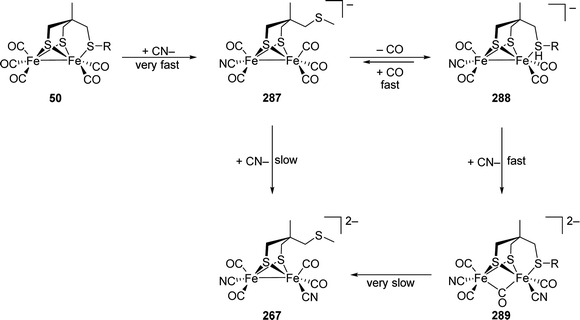 | ||
| Fig. 87 Proposed mechanism for the dicyanation of 50.138,139,385,413 | ||
Complex 299 closely resembles the Hox-CO state in terms of the ligand environment of the iron centre but not in their oxidation states. Through transient IR and EPR spectroscopy of the product obtained upon chemical and electrochemical electron oxidation of 267, formation of [Fe2(pdtMeSMe)(μ-CO)(CO)3(CN)2]− was proposed.379 With a comparable first coordination sphere, the same spin state and very similar IR bands with respect to the Hox-CO state, this complex was the first close resemblance of an actual state of the [FeFe]-hydrogenases. These spectroscopic similarities affirmed the assignment of the (unusual) oxidation states (FeIFeII) in the active site. The spectroscopically and theoretically studies on [Fe2(adtSMe)(CO)4(L)2]+/− (adtSMe = (methylthio)ethylbis(sulfidomethyl)amine, L = PMe3, CN−) further supported the suggested structure – however, comprising a bridgehead nitrogen atom as an additional detail.280,414,415
Notably, Tard et al. reported on complex 291, representing the hitherto only complete iron-sulphur framework of the H-cluster (Fig. 88).416 Contrary to the natural H-cluster, the [2Fe–2S]- and the [4Fe–4S]-clusters are interconnected by an organic thioether moiety instead of a cysteine residue, completing the H-cluster framework. The formal exchange of the methyl group of 50 by a [4Fe–4S]-cluster results in a downshift of the IR bands of about 15 cm−1. Electrochemical studies revealed that the [4Fe–4S]2+-cluster is reduced at milder potentials, than the [2Fe–2S]-cluster (compare Hredvs.Hred′, though the oxidation states of [2Fe]H vary). While complex 291 revealed HER activity, despite its remarkable structural resemblance with the H-cluster, further in-depth studies on this model are quite limited due to the inherent instability of the H-cluster mimic.416–418
In general, the electronic influence of the connection of the thioether to the dithiolate bridge is apparently small. From pdt- and adt-hexacarbonyls to the thioether substituted models 50 and 286 the highest-energy IR frequency shifts by 26 cm−1, respectively 21 cm−1 to lower wavenumbers.138,139,169,288 For the diethyl sulphide substituted pdt-complex a shift of 27 cm−1 is observed.366 For discrete and linked metallothioethers shifts of 30 to 38 cm−1 are reported.178,204,209,416,419
If the unprotected trithiol CH3C(CH2SH)3420 and its sila-substituted derivative157 are reacted with triiron dodecacarbonyl, the only isolable products are the tetra iron clusters 292E, in which two [2Fe–2S]-units are bridged by the two thiolate arms (Fig. 89).420–422
All in all, as shown for 50, an additional thioether strongly influences the reactivity of model complexes and enables the formation of the Hox-CO mimic 267+ with the complete first coordination sphere of the iron atoms in the enzyme.
5.3 Protonated H-cluster models
As a hydrogen forming catalyst, protonated states of the active site of [FeFe]-hydrogenases are an integral part of the catalytic cycle. Model complexes with bridging hydrides are readily formed upon protonation;277,278,423,424 however, their relevance for the catalytic cycle was questioned and is still under discussion (Section 3.10). Terminal hydrides, though rare in mimics, are more appealing as key intermediates for rapid H2 formation due to their lower reduction potential,154 their higher hydridic character,270 and the proximity to the amine proton shuttle by the adt-ligand.30The reactivity of hydrogenase mimics towards other nucleophiles than protons and nitrosyls was also extensively studied. While giving bridged complexes for a variety of electrophiles,425–435 terminal intermediates were reported as well.433,434 In addition, other electrophiles, especially alkylation agents, also showed cyanide,153,290 thiolate,404,436 or carbonyl53 centred reactivity as well.
It is worth to mention that in the case of terminal hydrides, a μ-CO band is detected.438 The spectroscopic properties of many protonated complexes have been summarised by Tschierlei et al. and we would like to direct the reader to this review for more detailed information.439
The structure of the bridging hydride complexes is very similar to the unprotonated complexes. The metal–metal distance is only slightly elongated (0.02 Å to 0.05 Å) upon protonation despite the loss of the Fe–Fe bond. In the face-sharing octahedrons the iron atoms are less displaced from the equatorial S2(CO)L planes compared to the displacement form the basal plane in the neutral complexes.153,277,278,440,441 Importantly, the high fluxionality of the FeL3 units is lost upon protonation consistent with higher site exchange barriers in the octahedral coordination environment.153,278
Stable diphosphine complexes with bridging hydrides are known since the 1970s from early studies by Poilblanc, Mathieu and coworkers.423,424,440 The protonation of Fe2(pdt)(CO)4(PMe3)2 (219pdt) gave the first and representative example for a bridging hydride [219pdt-μH]+ with a dithiolate bridge (Fig. 90).277,278 Subsequently, stable bridging hydrides were obtained by protonation of a variety of electron-rich cofactor mimics.270,278,326,342,353–355,445,446 The protonation behaviour of diphosphine bridged complexes Fe2(pdt)(CO)4(μ-diphosphine) shows remarkable dependence on the nature of the diphosphine. While the complexes with electron-poor, small-bite-angle phosphines dppm, dppe and (Ph2P)2NR are sluggishly protonated to give unstable bridging hydrides, complexes with the electron-rich dcpm and the more flexible chelating phosphines form stable bridging hydrides.326,342,353,354
Bridging hydride complexes are either not, or only slowly deprotonated by amine bases.278,283,342 However, the less basic but smaller chloride ion deprotonates bridging hydrides and can also increase the deprotonation rate by amine bases when added sub-stoichiometrically (Fig. 93).278,283,447
Protonated disubstituted phosphine and isocyanide complexes enable H/D exchange reactions between D2, D2O, alkenes, and Fe(μ-H)Fe under photolytic conditions. The reaction was proposed to proceed after dissociation of a carbonyl ligand, or a hydride shift to a single iron centre to provide a binding site for the substrate. This assumption is supported by the inhibition of the scrambling reactions by CO, acetonitrile, and in the case of D2/D2O by alkenes.277,278,355,404
After the first detection in the electrocatalytic proton reduction with a [2Fe–2P]-complex,448 the first terminal hydride [216edt-tH]+ observed in a [2Fe–2S]-complex was synthesised in 2005 by Rauchfuss and coworkers.438 In contrast to earlier studies, the complex was prepared by addition of a hydride source to the diferrous complex [Fe2(edt)(CO)2(PMe3)4(MeCN)](PF6)2 ([274edt]2+, Fig. 90). At low temperatures (−25 °C), this reaction yields a terminal hydride that was studied by NMR and IR spectroscopy and structurally characterised by X-ray diffraction. The isomerisation to the favourable bridging hydride [216edt-μH]+ occurs slowly at these temperatures (as well as in the solid state) but proceeds rapidly at room temperature. Notably, the corresponding complex with only three phosphine ligands showed no terminal hydride complex. Complexes [216xdt-tH]+ are also accessible by protonation of the corresponding complexes 216xdt.320 The protonation of the edt and pdt analogues yields a mixture of bridging and terminal hydrides, while the protonation of 216adt only yields the terminal hydride. Though the terminal hydrides [216xdt-tH]+ isomerise to the bridging hydrides [216xdt-μH]+ at room temperature, terminal hydrides are no intermediates in the initial formation of the bridging hydride in the case of the edt and pdt complexes. For the initial formation of the bridging hydride an intermolecular reaction from an S-protonated intermediate was proposed. Interestingly, [216edt-tH]+ releases hydrogen upon treatment with strong acids, which is not always observed for terminal hydrides, e.g. [216adt-tH]+ and [HFe2(pdt)(CO)2(κ2-dppv)2]+ ([233pdt-tH]+) and generally not observed for bridging hydrides.320,438,449
In contrast to the symmetric complexes 216xdt and 219xdt (xdt = edt, pdt),320,324,325 terminal hydrides were proposed to be intermediates in the protonation of the asymmetric complexes Fe2(xdt)(CO)4(κ2-L) (κ2-L = dppe, dmpe, dppv, phen, bis(NHC), NHC–PPh2; xdt = edt, pdt), Fe2(pdt)(CO)3(PMe3)(κ2-dppv), as well as in the sterically demanding complexes Fe2(xdt)(CO)2(κ2-dppv)2 (xdt = edt, pdt, adt, odt).154,210,336,340,363,372,437,450 In contrast, the protonation of Fe2(xdt)(CO)4(κ2-dppp)342 at −70 °C mainly yields bridging hydrides and for Fe2(edt)(CO)4−x(PMe3)x(κ2-dppv) (x = 0, 1)437 no terminal hydride is observed. Not only the dithiolate bridge but also the strength of the acid were reported to influence the occurrence of terminal hydride intermediates.373,451 Admittedly, especially in cases where bridging hydrides isomerise quickly, distinguishing between a terminal hydride as a necessary intermediate and a terminal hydride as a (side) product that isomerises quickly is not trivial and requires elaborated experiments.
While the asymmetric terminal hydride complexes isomerise quickly at low temperatures (−30 °C to −90 °C),336,340,363,372,437 the sterically crowded terminal hydrides [HFe2(xdt)(CO)2(κ2-dppv)2]+ [233xdt-tH]+ are reasonably stable at −20 °C.154,210,437 Unintuitively, protonation of the less electron-rich Fe(CO)3 unit in the asymmetric complexes is regularly observed under these conditions.336,340,363,437 A stable terminal hydride was reported for (Cp*)Fe(pdt)(μ-CO)Fe(κ2-dppe)H (293-tH), which only isomerises upon oxidation. Interestingly, the corresponding reduced bridging hydride partially isomerises to the terminal hydride – a process which is not observed for any other bridging hydride in context of hydrogenase mimics (Fig. 91).452
The adtR amine is protonated by strong acids (e.g. HOTf, HBF4/Et2O),151,168,177,183,196,203,346,354,447,453–459 while weaker acids (e.g. CF3COOH, HOAc) are not sufficiently acidic to protonate the hexacarbonyl complexes in organic media.195,343,460 Electron donating ligands on the iron core were reported to increase the basicity of the amine and allow for protonation with weaker acids,210,320,451,459 while some hexacarbonyl complexes are only partially protonated by triflic acid or deprotonated in neutral solution.454,459 Amine-functionalised phosphines show a similar protonation behaviour as the adt-bridge.152,302,303,350–352,461 In the IR spectrum of the N-protonated complexes, the bands are shifted by ca. 15 cm−1 under retention of the band structure.459 The reversibility of the N-protonation was demonstrated with amine bases.151,183,350,453–455 In electron-rich complexes bearing an adjacent amine, metal centred protonation is likewise observed. Importantly, in some cases the corresponding complexes lacking the amine are very slowly protonated or are only protonated by stronger acids.210,320,351 In accordance with similar basicities, this effect is attributed to reduced kinetic barriers and is crucial for rapid H2 formation.154,210,350,351 Due to two basic sites, the protonation behaviour of these mimics can be complex and is affected by several parameters. While in some cases the amine only facilitates the protonation of the iron centre by decreasing the kinetic barrier and itself remains unprotonated,154,462 mixtures of N- and Fe-protonated species152,350,351 as well as solely N-protonated complexes were obtained.151,447,455,459 The latter is observed if the amine is not in proximity to the site of metal protonation and can represent a metastable intermediate that slowly coverts to the bridging hydride.151,455,459 This tautomerization can be accelerated by chloride.455,459 Still, in some cases metal protonation is not observed at all.447,463 Both amine and iron can be the more basic site and accordingly be the thermodynamically favourable site for protonation. If the basicities of both sites are similar, the equilibrium between the ammonium and the hydride tautomer is influenced by the solvent,152,154,351,451 the used acid/counterion,351,451 and the basicity of the amine.225,352
In general, more polar solvents stabilise the ammonium tautomer as well as the ability of the counterion to form hydrogen bonds. With strong acids double-protonated species are accessible, where the hydride can occupy a terminal or a bridging position.151,154,320,447,451,455 It was shown that decreasing the basicity of the amine in Fe2(pdt)(CO)4((Ph2PCH2)NR) (294R) from 294Me to 294Ph is sufficient to prevent double-protonation by triflic acid (Fig. 92). This behaviour exemplifies the high acidity of the double-protonated complexes, which are sensitive to weak bases e.g. methanol, water or even acetonitrile.151,154,320,454,455 By NMR spectroscopy and single-crystal XRD hydrogen–hydrogen interactions were suggested in these complexes (Fig. 93).351,451
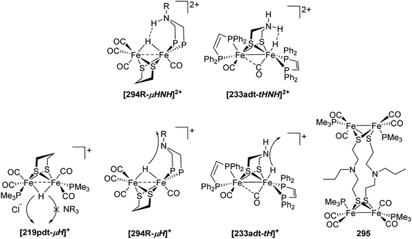 | ||
| Fig. 93 Top: H–H interaction in double-protonated complexes. Bottom: Deprotonation of hydride complexes and structure of complex 295 (Note: P = PPh2 in 294R). | ||
The deprotonation of the ammonium proton is typically fast, while the deprotonation rate of the hydride is dependent on the structure of the complex and the base used. In the complexes [294R-μH]+ and [233adt-tH]+ where the amine is in close proximity to the hydride, the deprotonation of the hydride can be accomplished with amine or phosphine bases (Fig. 93). The formal exchange of the NH groups by CH2 groups prohibits any deprotonation,210,351,464,465 while an oxygen atom showed a decreased, yet existent proton relay ability.210 In the case of 295 (Fig. 93), the iron protonated tautomer is metastable and rearranges to the N-protonated tautomer. If the hydride and the amine are spatially separated, the amine does not function as a proton relay and deprotonation by amine bases is prohibited.151,455 However, selective deprotonation by chloride was reported to be efficient.447
To emphasize the importance of the adjacent amine, we briefly summarize the different reactivities of the complexes shown in Fig. 94. The initial product of the protonation of 219adt is the ammonium salt and not the bridging hydride as for 219pdt151,277,278,324,325,455 and in contrast to 294R, 294C is only protonated by H(Et2O)BF4 if used in large excess.342,351 While the protonation of 216adt and 233adt is feasible with medium strength acids as ammonium or phosphonium salts, the protonation of their pdt analogues requires strong acids.210,320 Accordingly, in the cases where the protonation site is in close proximity to the amine (216adt, 233adt, 294R), the protonation rate of the iron centre is accelerated. The same was observed for the deprotonation of the terminal hydride in [233adt-tH]+ and the bridging hydride in [294Me-μH]+, but not for [219adt-μH]+, where the bridging hydride and the amine are spatially separated.210,351,455 At last, all amine containing complexes except from 294Ph allow for double-protonation to give a complex bearing an ammonium proton and a hydride.
VI Electrochemistry of H-cluster models – redox and catalytic properties
6.1 Redox chemistry of H-cluster models
Due to the mild potentials at which the native enzyme operates the hydrogen conversion/formation, models of its active site were extensively studied as noble-metal-free catalysts for the hydrogen evolution reaction. In order to evaluate potential catalysts, the redox behaviour of numerous complexes described in the previous sections was intensively investigated. In general, the interplay of the reduction potentials and the basicity of these clusters heavily influences the proton-coupled electron transfer processes that are crucial for HER.Before describing the electrocatalytic capabilities of the active site models to serve as potent HER catalysts and the specific mechanisms involved, a short discussion on the non-catalytic redox behaviours of the diiron subsite models is advisable. Subsite models are generally in the FeIFeI resting state and undergo reversible or quasi-reversible (stepwise) reductions. Therefore, the complexes act as precatalysts and form the actual catalyst upon reduction. In the anodic scan, the mimics commonly display a one-electron oxidation resulting in a FeIIFeI state followed by another electron oxidation resulting in a FeIIFeII state. Herein the four most discussed complexes i.e. Fe2(pdt)(CO)6, Fe2(adt)(CO)6, Fe2(odt)(CO)6 and Fe2(sdt)(CO)6 will be considered. However, the oxidation only plays a minor role in the chemistry of hydrogenases and we will thus mainly focus on their reduction properties. In the following, all given potentials are referenced versus the ferrocene/ferrocenium couple if not otherwise specified.
Fe2(pdt)(CO)6 (20) displays a quasi-reversible single-electron reduction at E1 = −1.74 V (−1.34 V vs. NHE) in MeCN and a second irreversible reduction is observed at a more negative potential of −2.35 V (−1.95 V vs. NHE).466 Notably, the reduction potential (E1) for 20 has been reported with an averaged value of −1.66 V.283,289,302,317,329,367 The azadithiolate model Fe2(adt)(CO)6 (2) is reduced from a FeIFeI to a FeIFe0 state at −1.58 V.170 This value is slightly less negative than the reduction potential of 20, which is reasonable due to the higher electronegativity of nitrogen compared to carbon and therefore a decreased electron density at the diiron core. Likewise, Fe2(odt)(CO)6 (136) undergoes a single-electron quasi-reversible reduction at −1.59 V and a further irreversible reduction at −2.1 V.204 Furthermore, the sulphur analogue Fe2(sdt)(CO)6 (139) is reduced to the FeIFe0 stage at −1.51 V followed by reduction at −1.94 V to the Fe0Fe0 state.211 Thus, the bridgehead atom exerts only a small influence on the non-catalytic reduction behaviour of these models. Comparatively, models with aromatic thiolate linkers, especially Fe2(bdt)(CO)6 (149), are reduced at milder potentials (about −1.3 V).221,467,468 The reduction comprises two overlapping single-electron processes. It is worth mentioning that the reduction of 149 proceeds with structural changes wherein one of the Fe–S bonds is cleaved, and a CO ligand transforms from a terminal to a bridging position. This geometric transformation causes a potential inversion, making the second reduction more feasible than the first one (Fig. 95).468–471
 | ||
| Fig. 95 Scheme depicting the reduction of Fe2(bdt)(CO)6 based on spectroscopic data and DFT studies.470–472 | ||
6.2 Influence of modified thiolate bridges on the redox behaviour of H-cluster models
A common method to alter the redox-properties of metal centres is manipulation of their ligand environment and hence their electron density, which influences thermodynamics and kinetics of the redox-event. For C2-substituted Fe2(pdt)(CO)6-like models, the inductive effect of the substituent is therefore decisive for the potential shift. Alkyl chains, that exhibit a +I effect, are expected to negatively shift the reduction potential due to the increasing electron density. However, models Fe2((SCH2)2CR1R2)(CO)6 (R1 = R2 = Me (296); R1 = R2 = Et (297); R1 = Et, R2 = Bu (298)), bearing methyl-, ethyl- or butyl-groups at the bridging position, undergo the first reduction at −1.61, −1.67 and −1.64 V, respectively.473 These values are within the reported range for the reduction of 20. Thus, inductive effects of alkyl-substituents at this specific position can be neglected. Contrary, substituents bearing an electron withdrawing group, should direct the reduction potential to more positive values due to the decreased electron density. Here, especially ketons,137 carboxylates133,137,141 and alcohols134–136,474 are present in literature. For example, complexes 35 and 38 are functionalized by a hydroxy group in C2 position and can be reduced at −1.61 and −1.60 V, respectively. Compared to the alkyl-substituted PDT-models and unsubstituted 20, the reduction potential is barely shifted to more positive values, which again shows the limited influence of inductive effects at the C2-position.134,135 The same is true for ester bearing models 38, 43c and 43d that show a reduction potential of approx. −1.59 V.133,137 The strongest shift in reduction potential (−1.53 V) is observed for model 39, which however, has kinetic reasons since the reduced state of this model is stabilized by an intermolecular H-bond between the hydroxy group and the reduced iron centre.136 These few examples show that the influences of C2-substituents on the reduction potential of Fe2(pdt)(CO)6-like models is generally low and highlights the electronic remoteness of this position within the mimics.Along this line, substituted azadithiolate models likewise possess reduction potentials between −1.49 V to −1.59 V (Section 6.5.2). Contrary to the pdt-models, more pronounced shifts in the reduction potential are observed upon modifying the mimics at the nitrogen atom. For example, alkyl substituted models are generally reduced at more cathodic potential (−1.63 V to −1.68 V).182,186,190 Furthermore, strongly electron withdrawing systems attached to a phenyl-ring such as in Fe2(adtR)(CO)6 (R = p-C6H4NO2, 120) cause a reduction potential shift to −1.42 V.194
In contrast to Fe2(pdt)(CO)6 and Fe2(adt)(CO)6 models, the aryl-substituents of Fe2(bdt)(CO)6 have a severe influence on the redox potentials of the hydrogenase mimics (Section 6.5.6).222,228,232,239,240,242 Notably, bdt-models comprising ligands with +I effect are rare in literature and show only slightly increased electron density at the diiron centre. Complex 153 is a good example for such a system and possesses a single methyl group in m/p-position. The complex shows a reduction potential of −1.37 V compared to −1.36 V for 149.222 Attachment of electron withdrawing groups, especially chlorides, reduce the electron density at the diiron core to a significant extent. The most prominent effect can be observed in 152 with a per-chlorinated benzene ring and exhibits a reduction potential of −1.13 V in MeCN.226 Moreover, models with N-heterocyclic substituents (e.g. 2,3-quinoxalinedithiolate) are more conveniently reduced owing to the decreased electron density on the diiron centre due to the electron withdrawing N-substituted aryl rings (Section 6.5.6).222,228,229
In contrast to Fe2(bdt)(CO)6 and its analogues, 1,8-naphthalenedithiolate models mainly undergo two single-electron reductions (Section 6.5.7).239,242,244,247,251 The first reduction usually occurs at −1.52 V, which is approx. 200 mV more negative compared to Fe2(bdt)(CO)6.239 Electron density manipulating groups alter the redox potential in the same way as described above for bdt-derivatives but to a somewhat lesser extent.
The biphenyl475 as well as the o-carborane476 modified Fe2S2 complex also undergoes two successive single step electron reductions. Moreover, due to the delocalisation of the negative charge on the aromatic ring and rigidity of the naphthalene-linker these models prove to generate more stable reduced states. In addition, the phenanthrene-4,5-dithiolate-bridged compound 182 is reduced at more positive potentials due to the enhanced electron delocalization of the phenanthrene system.240
Despite of the increased electron density at the diiron centre in chalcogenide-substituted complexes, anodically shifted reduction potentials upon sulphur to chalcogenide exchange were observed (e.g.39vs.40).133,136,145,146,204,205,211,239,240,251,477 This positive shift is overall <50 mV and can be rationalised by the improved stabilization of the reduced species. Furthermore, Weigand and coworkers further reported decreasing reorganization energies for the reduction to a FeIFe0-species within the S, Se and Te series that partially counteracts the trend of increasing electron density at the diiron centres.146
In contrast, Fe2((ECH2)N-p-C6H4R)(CO)6 derivatives show almost no shift in the reduction potentials for the respective selenium containing models (R = H, E128 = −1.57 V vs. E128 = −1.58 V; R = NO2E130 = −1.48 V vs. E120 = −1.49 V).198 Along this line, it is worth to mention that the reduction of 2 (adt) and 96 (adSe) occurs at almost same potentials of approx. −1.2 V vs. SHE.32 Thus, the experimentally observed shifts are depending on the interplay of the electron density modulating properties of the headgroup and the chalcogenide as well as the counteracting change of reorganisation energies for the reduction.
6.3 Influence of CO-ligand substitution on the redox behaviour of H-cluster models
While the carbonyl to cyanide replacement aims at replicating systems that resemble the natural subsite more closely, the complicated electronic behaviour of the cyanide restricts their investigations; in this regard many studies adopted phosphines and carbenes as non-native ligand systems. Herein, it is necessary to highlight that the redox behaviour of the metal centres are considerably affected by the nature of the binding ligand as the LUMO has major contributions of metal–metal and metal–ligand anti-bonding orbitals.138| Complex | Ligand | E pc,mono [V] n = 1 | E pc,di [V] n = 2 | ΔE vs. CO [V] | Ref. |
|---|---|---|---|---|---|
| Fe2(pdt)(CO)6 | −1.66 | 215, 283, 289, 302, 317, 329 and 367 | |||
| Fe2(pdt)(CO)6−n(L)n | PMe3 | −1.94 | −2.31 | 0.28, 0.37 | 221, 467 and 468 |
| Fe2(pdt)(CO)6−n(L)n | PMe2Ph | −1.90 | −2.30 | 0.24, 0.40 | 283 |
| Fe2(pdt)(CO)6−n(L)n | PPh3 | −1.84 | 0.18 | 291 | |
| Fe2(pdt)(CO)6−n(L)n | P(OEt)3 | −1.81 | −2.27 | 0.15, 0.46 | 473 |
| Fe2(pdt)(CO)6−n(L)n | P(OMe)3 | −1.98 | −2.30 | 0.32, 0.32 | 473 |
| Fe2(pdt)(CO)6−n(L)n | PTA | −1.94 | −2.14 | 0.28, 0.20 | 473 |
| Fe2[(SCH2)2(NH)](CO)6 | −1.58 | 473 | |||
| Fe2(adt)(CO)6−n(L)n | PMe3 | −1.88 | 0.30 | 170 | |
| Fe2(adt)(CO)6−n(L)n | PPh3 | −1.70 | 0.12 | 170 |
The alteration of Epc for chelating phosphine ligands is comparable to the shifts observed for mimics possessing two monodentate phosphines.130,328,338,479 For example, the reduction potential of Fe2(pdt)CO4(κ2-dppe) (232pdt) is with −2.33 V similar to that of Fe2(pdt)CO4(PMePh2)2 (299) with −2.30 V. Likewise, analogues with bridging phosphine ligands reveal comparable reduction potentials as their chelating counterparts.130,328,338
| Complex | Ligand | E pc,mono [V] n = 1 | E pc,di [V] n = 2 | ΔE vs. CO [V] | Ref. |
|---|---|---|---|---|---|
| Fe2(pdt)(CO)6−n(L)n | −1.66 | 215, 283, 289, 302, 317, 329 and 367 | |||
| [Fe2(pdt)(CO)6−n(L)n]n− | CN− | −2.17 | −2.72 | 0.51, approx. 0.55 | 221, 467 and 468 |
| Fe2(pdt)(CO)6−n(L)n | CNMe | −1.81 | −2.08 | 0.15, 0.27 | 283 |
| Fe2(pdt)(CO)6−n(L)n | IMe | −2.06 | −2.47 | 0.40, 0.41 | 291 |
| Fe2(pdtMe)(CO)6 | −1.61 | 473 | |||
| Fe2(pdtMe)(CO)6−n(L)n | IMes | −2.01 | 0.40 | 473 | |
| Fe2(pdtEt)(CO)6 | −1.67 | 473 | |||
| Fe2(pdtEt)(CO)6−n(L)n | IMes | −2.02 | 0.35 | 473 |
| Complex | E pc vs. SCE (vs. Fc+/0) [V] | E pa vs. SCE (vs. Fc+/0) [V] |
|---|---|---|
| Fe2(pdtMeSMe)(CO)5 | −1.38 (−1.78) | +0.67 (+0.27) |
| Fe2(pdtMeSBn)(CO)5 | −1.36 (−1.76) | +0.77 (+0.37) |
| [Fe2(pdtMeSMe)(CN)(CO)4]− | −1.83 (−2.23) | +0.17 (−0.23) |
| [Fe2(pdtMeSBn)(CN)(CO)4]− | −1.83 (−2.23) | +0.12 (−0.28) |
| [Fe2(μ-CO)(pdtMeSMe)(CN)2(CO)3]2− | −2.40 (−2.83) | −0.10 (−0.03) |
| [Fe2(pdtMeSMe)(CN)2(CO)4]2− | −2.40 (−2.83) | −0.25 (−0.65) |
| [Fe2(pdtMeSBn)(CN)2(CO)4]2− | −2.40 (−2.83) | −0.26 (−0.66) |
6.4 Remarks on the electrochemical oxidation of H-cluster models
As described above, the electron donating capabilities of the ligands effect the complexes reduction potentials. Analogously, the oxidation processes are likewise affected by ligand exchanges. Thus, strong donor ligands such as PMe3 and CN−e.g. cause a cathodic shift of Epa (Table 10). Importantly, the influence of the ligand substitution is greater on the oxidation potentials than on the reduction potentials, a trend that can be explained by different HOMO–LUMO participation. As oxidation involves removal of electrons from the HOMO, which usually has a strong contribution of the Fe–Fe bond, attaching strong donor ligands to the iron atoms directly eases this process. However, in case of any reduction, the less metal-centred LUMO with a significant Fe–S bond character is involved and renders this process comparatively less sensitive to ligand exchange.138| Complex | Ligand | E pa [V] | ΔE vs. (CO)6 [V] | Ref. |
|---|---|---|---|---|
| Fe2(pdt)(CO)6 | +0.80 | |||
| [Fe2(pdt)(CO)5(CN)]− | CN− | +0.13 | 0.67 | 283 |
| [Fe2(pdt)(CO)4(CN)2]2− | CN−, CN− | −0.52 | 0.66 | 289 |
| Fe2(pdt)(CO)5(CNMe) | CNMe | +0.57 | 0.17 | 283 |
| Fe2(pdt)(CO)4(CNMe)2 | CNMe, CNMe | +0.21 | 0.42 | 283 |
| Fe2(pdt)(CO)5(PMe3) | PMe3 | +0.23 | 0.57 | 317 |
| Fe2(pdt)(CO)4(PMe3)2 | PMe3, PMe3 | −0.20, −0.14 | 0.43, 0.37 | 153 and 215 |
| Fe2(pdt)(CO)5(P(OEt)3) | P(OEt)3 | +0.44 | 0.36 | 317 |
| Fe2(pdt)(CO)4(P(OEt)3)2 | P(OEt)3, P(OEt)3 | 0.00 | 0.44 | 317 |
| Fe2(adt)(CO)6 | +0.59 | 170 | ||
| Fe2[(adt)(CO)5(CN)]− | CN− | −0.043 | 0.63 | 478 |
| Fe2(adt)(CO)5(PPh3) | PPh3 | +0.19 | 0.40 | 170 |
The first oxidation of [FeFe]-hydrogenase mimics leads to bivalent FeIFeII species, which is related to the Hox state of the native active site. The effect of the dithiolate bridge on the stability of the oxidised state was reported by Justice et al. investigating Fe2(xdt)(CO)3(PMe3)(dppv) (235xdt, xdt = edt, pdt, adt).337 Upon chemical oxidation with Cp2FePF6 in MeCN, rotated states mimics with bridging CO and NCMe coordination at the “open site” resulting in [Fe2(xdt)(CO)2(μ-CO)(PMe3)(dppv)(NCMe)]2+ (235xdt(MeCN)2+) was observed. Notably, the dicationic state of edt was found to be stable at room temperature, while the pdt bridged model decomposed within 30 minutes at −40 °C. Remarkably, no dicationic species was yet detected for any adt analogue. Based on these observations, it was concluded that bulky ligands, e.g. PMe3 are not accommodated by pdt and adt linkers in the rotated state, due to steric limitations which are not present in edt-bridged derivative, thereby explaining the preference of nature to apply sterically less demanding CN− and CO as ancillary ligands. Adding substituents to the amine bridgehead allows for the facile oxidation of such complexes as seen in e.g. Fe2(adtBn)(CO)4(dmpe) (265).483 The described reason for the stabilization of the rotated FeIFeII-oxidation state is an anagostic interaction between the methyl group of the Bn substituent and the iron centre (Fe⋯H–C), which also allows its facile second oxidation. It was also observed that these weak interactions are lost under CO atmosphere. In this case, the [FeIIFeI(adtBn)(CO)4(dmpe)]+ is stabilized by binding of an additional carbonyl ligand to an iron centre, rather than an anagostic stabilisation (Fig. 96).
6.5 Redox potentials of selected H-cluster models
While the above-mentioned trends are explained on distinct examples, comparable trends can be observed for numerous synthetic mimics. The large number of mimics would certainly distract the reader from the actual message and trends observed. However, to present a full picture and allow the reader to obtain the formation without a detailed literature research, we subsequently present the redox properties of numerous complexes in tabular form (Tables 11–23).The tabular section can be summarized as follows:
• Fe2S2 models undergo electrochemical reductions resulting in a Fe0Fe0 state which might be achieved in concerted two-electron transfer steps or require two single-electron potential-separated reductions.
• Functionalisation of the dithiolate bridge has only minimal influence on the redox potentials.
• Upon CO-replacement, electron donating ligands shift both, the reduction and oxidation potential, towards more cathodic values. The opposite is true for electron withdrawing ligands. However, the oxidation potential is more affected due to the nature of the HOMO and LUMO orbitals.
These investigations of the diiron models in the absence of acids give a fair idea about their respective redox properties, which can be mainly correlated to the basicity of the Fe–Fe bond. This basicity is an important factor for the catalytic mechanism of hydrogen evolution, which will be discussed in Section 6.6.
| L1 | Solvent | E pc(FeIFeI/FeIFe0)/V | E pc(FeIFe0/Fe0Fe0)/V | E pa(FeIFeI/FeIFeII)a/V | Ref. |
|---|---|---|---|---|---|
a Second oxidation corresponds to FeIFeII/FeIIFeII.
b Reported vs. Ag/AgCl.
c Reported vs. NHE, converted.
d Electron count not defined.
e La = CO(bpy)(ppy)2Ir.
f Reported vs. 0.01 M Ag/Ag(NO3), converted.
g R1 = 6-(diphenylphosphaneyl)pyridin-2-yl, R2 = 6-(diphenylphosphaneyl)pyrimidin-4-yl, R3 = 6-(tert-butyl)pyrimidin-4-yl.
h 1,3-Bis(2-picolyl)imidazol-2-ylidene.
i Reported vs. Ag/AgCl, converted.
j 4-(Ethylthio)pyridine.
k DAPTA = 3,7-diacetyl-1,3,7-triaza-5-phosphabicyclo[3.3.1]nonane.
l Reference for redox potentials in different H2O![[thin space (1/6-em)]](https://www.rsc.org/images/entities/char_2009.gif) : :![[thin space (1/6-em)]](https://www.rsc.org/images/entities/char_2009.gif) MeCN ratios. MeCN ratios.
|
|||||
| CO | MeCN | −1.65 to −1.74 | −2.32 | 0.74 to +0.82 | 215, 283, 289, 302, 317, 329 and 367 |
| CO | THF | −1.25b | 283 | ||
| PTA | MeCN | −1.94c | +0.34 | 302 | |
| P(NC4H8O)3 | MeCN | −1.86 | +0.27d | 129 | |
MeCN/H2O 10![[thin space (1/6-em)]](https://www.rsc.org/images/entities/char_2009.gif) : :![[thin space (1/6-em)]](https://www.rsc.org/images/entities/char_2009.gif) 1 1 |
−1.84 | ||||
MeCN/H2O 3![[thin space (1/6-em)]](https://www.rsc.org/images/entities/char_2009.gif) : :![[thin space (1/6-em)]](https://www.rsc.org/images/entities/char_2009.gif) 1 1 |
−1.80 | ||||
MeCN/H2O 2![[thin space (1/6-em)]](https://www.rsc.org/images/entities/char_2009.gif) : :![[thin space (1/6-em)]](https://www.rsc.org/images/entities/char_2009.gif) 1 1 |
−1.78 | ||||
| (PPh2)NH((CH2)2NMe2) | −1.87 | +0.348 | 303 | ||
| (PPh2)NH(o-C6H4NH2) | −1.86 | +0.259 | 303 | ||
| PPh2-(C6H4)-2CH2N(Me)2 | −1.85 | 303 | |||
| Val-Epa-Leu | MeCN | −1.93 | +0.22 | 306 | |
MeCN/H2O 3![[thin space (1/6-em)]](https://www.rsc.org/images/entities/char_2009.gif) : :![[thin space (1/6-em)]](https://www.rsc.org/images/entities/char_2009.gif) 1 1 |
ND | ||||
MeCN/H2O 3![[thin space (1/6-em)]](https://www.rsc.org/images/entities/char_2009.gif) : :![[thin space (1/6-em)]](https://www.rsc.org/images/entities/char_2009.gif) 2 2 |
ND | ||||
| Val-Ipa-Leu | MeCN | −1.90 | +0.26 | 306 | |
MeCN/H2O 3![[thin space (1/6-em)]](https://www.rsc.org/images/entities/char_2009.gif) : :![[thin space (1/6-em)]](https://www.rsc.org/images/entities/char_2009.gif) 1 1 |
−1.78 | +0.22 | |||
MeCN/H2O 3![[thin space (1/6-em)]](https://www.rsc.org/images/entities/char_2009.gif) : :![[thin space (1/6-em)]](https://www.rsc.org/images/entities/char_2009.gif) 2 2 |
−1.74 | +0.22 | |||
| Val-Ppa-Leu | MeCN | −1.82 | +0.31 | 306 | |
MeCN/H2O 3![[thin space (1/6-em)]](https://www.rsc.org/images/entities/char_2009.gif) : :![[thin space (1/6-em)]](https://www.rsc.org/images/entities/char_2009.gif) 1 1 |
−1.77 | +0.29 | |||
MeCN/H2O 3![[thin space (1/6-em)]](https://www.rsc.org/images/entities/char_2009.gif) : :![[thin space (1/6-em)]](https://www.rsc.org/images/entities/char_2009.gif) 2 2 |
−1.72 | +0.32 | |||
| PPh2(S(o-C6H4NH2)) | MeCN | −1.79 | −2.06 | 307 | |
| PPh2(p-C6H4NH2) | MeCN | −1.85 | −2.10 | 307 | |
| PPh2(S(o-C6H4NH2-Lae)) | MeCN | −1.76 | +0.34 | 307 | |
| PPh2(p-C6H4NH2-Lae) | MeCN | −1.83 | +0.36 | 307 | |
| PMe3 | MeCN | −1.94f | +0.31, +0.65 | 317 | |
| PMe2Ph | MeCN | −1.90f | +0.25, +0.66 | 317 | |
| PPh3 | MeCN | −1.84f | +0.26, +0.62 | 317 | |
| −1.87 | −2.24 | + 0.27, +0.66 | 215 | ||
| P(OEt)3 | MeCN | −1.81f | +0.44, +0.63 | 317 | |
| PPh2Py | −1.74 | +0.46, +0.68 | 319 | ||
| PPy3 | −1.66 | +0.65 | 319 | ||
| PPh2NH(p-C6H4Br) | MeCN | −1.80 | 334 | ||
| PPh2NH(p-C6H4Me) | MeCN | −1.82 | 334 | ||
| PPh2(R1)g | DCM | −2.05 | 305 | ||
| PPh2(R2)g | DCM | −2.02 | −2.17 | 305 | |
| PPh2(R3)g | DCM/DMF 1![[thin space (1/6-em)]](https://www.rsc.org/images/entities/char_2009.gif) : :![[thin space (1/6-em)]](https://www.rsc.org/images/entities/char_2009.gif) 4 4 |
−1.83 | −2.07 | 305 | |
| IMe | MeCN | −2.06/−2.01 | +0.11 | 291 and 361 | |
| IMes | MeCN | −2.10 | +0.11 | 361 | |
| IMes | −2.10c | +0.11, +0.72 | 362 | ||
| IMeMes | MeCN | −2.12 | +0.23 | 361 | |
| IPich | MeCN | −2.07f | +0.10 | 364 | |
| SEt2 | MeCN | −1.72i | 367 | ||
| S(CH3CH2)((CH2)2Cl) | MeCN | −1.76i | 367 | ||
| S(CH2CH3)(C6H5) | MeCN | −1.77i | 367 | ||
| SO(CH2CH2CH3)2 | MeCN | −1.65i | 367 | ||
| SO(CH3)2 | MeCN | −1.68i | 367 | ||
| MeCN | MeCN | −1.68 | 369 | ||
| NH2n-Pr | MeCN | −1.80 | 369 | ||
| PySEtj | MeCN | −1.65i | −2.22 | 370 | |
| P(piperidyl)3 | MeCN | −1.98 | +0.18 | 484 | |
| P(OMe)3 | MeCN | −1.98 | −2.29 | +0.37 | 485 |
| DAPTAk | MeCNl | −1.83c | 486 | ||
| CNMe | MeCN | −1.81i | +0.57 | 283 | |
| CN− | MeCN | −2.17i | +0.13 | 283 | |
| Ligands: Fe1//Fe2 | Solvent | E pc(FeIFeI/FeIFe0)/V | E pc(FeIFe0/Fe0Fe0)/V | E pa(FeIFeI/FeIFeII)a/V | Ref. |
|---|---|---|---|---|---|
a Second oxidation corresponds to- FeIFeII/FeIIFeII.
b Reported vs. NHE, converted.
c Electron count not defined.
d Reference for redox potentials in different H2O![[thin space (1/6-em)]](https://www.rsc.org/images/entities/char_2009.gif) : :![[thin space (1/6-em)]](https://www.rsc.org/images/entities/char_2009.gif) MeCN ratios.
e dppf = 1,10-bis(diphenylphosphino)ferrocene.
f Reported vs. 0.01 M Ag/Ag(NO3), converted.
g Reported vs. Ag/AgCl.
h FeIFeI/Fe0Fe0.
i 1-Methyl-3-(2-pyridyl)imidazol-2-ylidene.
j FeIFeI/FeIIFeII.
k Reported vs. Ag/AgCl, converted.
l Under CO.
m Reported vs. SCE, converted. MeCN ratios.
e dppf = 1,10-bis(diphenylphosphino)ferrocene.
f Reported vs. 0.01 M Ag/Ag(NO3), converted.
g Reported vs. Ag/AgCl.
h FeIFeI/Fe0Fe0.
i 1-Methyl-3-(2-pyridyl)imidazol-2-ylidene.
j FeIFeI/FeIIFeII.
k Reported vs. Ag/AgCl, converted.
l Under CO.
m Reported vs. SCE, converted.
|
|||||
| PTA//PTA | MeCN | −2.18b | +0.00 | 302 | |
| P(NC4H8O)3//P(NC4H8O)3 | MeCN | −2.08 | +0.01c | 129 | |
| κ2-(PPh2)2N-(CH2)2NMe2BzBr | MeCNd | −2.10 | +0.06 | 130 | |
MeCN![[thin space (1/6-em)]](https://www.rsc.org/images/entities/char_2009.gif) : :![[thin space (1/6-em)]](https://www.rsc.org/images/entities/char_2009.gif) H2O (3 H2O (3![[thin space (1/6-em)]](https://www.rsc.org/images/entities/char_2009.gif) : :![[thin space (1/6-em)]](https://www.rsc.org/images/entities/char_2009.gif) 2) 2) |
−1.92 | +0.06 | |||
| μ-(PPh2)2N-(CH2)2NMe2BzBr | MeCNd | −2.09 | +0.40 | 130 | |
MeCN![[thin space (1/6-em)]](https://www.rsc.org/images/entities/char_2009.gif) : :![[thin space (1/6-em)]](https://www.rsc.org/images/entities/char_2009.gif) H2O (3 H2O (3![[thin space (1/6-em)]](https://www.rsc.org/images/entities/char_2009.gif) : :![[thin space (1/6-em)]](https://www.rsc.org/images/entities/char_2009.gif) 2) 2) |
−1.93 | +0.42 | |||
| μ-dppfe | MeCN | −2.10 | −2.19 | +0.05 | 311 |
| PMe2Ph//PMe2Ph | MeCN | −2.30f | −0.14, +0.20 | 317 | |
| P(OEt)3//P(OEt)3 | MeCN | −2.27f | +0.00 | 317 | |
| P(Ph2Py)3//P(Ph2Py)3 | −1.92 | +0.32, +0.72 | 319 | ||
| P(Py)3//P(Py)3 | −1.70 | +0.62 | 319 | ||
| μ-dppm | MeCN | −2.28f | +0.22, +0.60 | 183 | |
| κ2-Me2dppm | MeCN | −2.16g | −2.23 | −0.19, +0.04 | 328 |
| μ-Me2dppm | MeCN | −2.50 | +0.74 | 328 | |
| μ-(PPh2)2NPr | MeCN | −2.17 | −2.46 | +0.33 | 329 |
| κ2-(PPh2)2N(allyl) | MeCN | −2.19 | −0.11 | 330 | |
| DCM | −2.23 | +0.07 | |||
| μ-(PPh2)2N(allyl) | MeCN | −2.15 | +0.31 | 330 | |
| DCM | −2.23 | +0.65 | |||
| κ2-(PPh2)2N(p-C6H4Me) | MeCN | −2.21 | 334 | ||
| κ2-dppe | MeCN | −2.07g | 338 | ||
| THF | −2.12 | ||||
| μ-dppe | MeCN | −2.23 | 338 | ||
| THF | −2.37 | ||||
| IMe//IMe | MeCN | −2.47 | 291 | ||
| IMes//PMe3 | MeCN | −2.36 | −0.47 | 361 | |
| IMeMes//PMe3 | MeCN | −2.52 | −0.33 | 361 | |
| IMe//PMe3 | MeCN | −2.53 | −0.24 | 361 | |
| κ2-IMe-CH2-IMe | MeCN | −2.42h | −0.41 | 363 | |
| κ2-NHCMePyi | MeCN | −2.16f | −0.16 | 364 | |
| κ2-bpy | MeCN | −2.06 | 371 | ||
| DCM | −0.25 | ||||
| P(OMe)3//P(OMe)3 | MeCN | −2.30 | +0.12j | 485 | |
| PMe3//PMe3 | MeCN | −2.31,k −2.37 | −0.20, −0.14 | 153 and 215 | |
| PMe3,NO+ | DCM | −0.36g | −1.03 | 381 | |
| PMe3, NO+//PMe3 | DCM | −0.64 | −0.98 | 381 | |
| κ2-(Ph2PCH2)2NCH3 | DCM | −2.3 | −0.17 | 152 | |
| PMe2Ph//PMe3 | MeCNl | −2.20f | −0.08 | 487 | |
| PMe2Ph//PPh3 | MeCNl | −2.09f | +0.03 | 487 | |
| PMe2Ph//P(OEt)3 | MeCNl | −2.17f | +0.01 | 487 | |
| PMe3//P(OEt)3 | MeCNl | −2.16f | +0.03 | 487 | |
| PPh3//P(OEt)3 | MeCNl | −2.06f | +0.13 | 487 | |
| PCy3//P(OEt)3 | Toluene/MeCN 1![[thin space (1/6-em)]](https://www.rsc.org/images/entities/char_2009.gif) : :![[thin space (1/6-em)]](https://www.rsc.org/images/entities/char_2009.gif) 3l 3l |
−2.14f | +0.14 | 487 | |
| PMe3//PPh3 | MeCNl | −2.12f | +0.02 | 487 | |
| PMe3//PCy3 | Toluene/MeCN 1![[thin space (1/6-em)]](https://www.rsc.org/images/entities/char_2009.gif) : :![[thin space (1/6-em)]](https://www.rsc.org/images/entities/char_2009.gif) 3l 3l |
−2.15f | −0.02 | 487 | |
| DAPTA//DAPTA | MeCN | −2.06b | 486 | ||
| DAPTA//PTA | MeCN | −2.14b | 486 | ||
| PMe3//CN− | MeCN | −2.58k | −0.39 | 150 | |
| CNMe//CNMe | MeCN | −2.08k | +0.21 | 283 | |
| CN−//CN− | MeCN | −2.72m | −0.50 | 289 | |
| CN−//CN− | MeCN | −2.72k | −0.52 | 283 | |
| Dithiolate | Ligands: Fe1//Fe2 | Solvent | E pc(FeIFeI/FeIFe0)/V | E pc(FeIFe0/Fe0Fe0)/V | E pa(FeIFeI/FeIFeII)a/V | Ref. |
|---|---|---|---|---|---|---|
| a Second oxidation corresponds to- FeIFeII/FeIIFeII. b Reported vs. Ag/AgCl, converted. c Under CO. d Reported vs. 0.01 M Ag/Ag(NO3), converted. e FeIFeI/FeIIFeII. f Additional unidentified process(es) involved. g Electron count not defined. h FeIFeI/Fe0Fe0. i ECE process. | ||||||
| S16 | MeCN | −1.64b | −2.40 | 141 and 144 | ||
| S16 | MeCNc | −1.64 | −2.51 | |||
| S16 | PMe3//PMe3 | MeCN | −2.42 | 141 | ||
| S17 | MeCNc | −1.67 | −2.60 | 141 | ||
| S18 | MeCN | −1.58d | −1.97 | +1.01 | 133 | |
| S19 | MeCN | −1.54d | −2.10 | +0.89 | 133 | |
| S4 | MeCN | −1.61d | −2.23 | +0.77 | 134 | |
| S5 | MeCN | −1.60d | −2.26 | +0.70 | 135 | |
| S6 | MeCN | −1.60d | −2.17 | +0.79 | 135 | |
| S15 | MeCN | −1.61 | −2.17 | +0.75 | 479 | |
| S15 | PPh3 | MeCN | −1.78 | +0.39 | 479 | |
| S15 | κ1-dppm | MeCN | −1.80 | −2.16 | +0.19 | 479 |
| S15 | μ-dppm | MeCN | −2.22 | 479 | ||
| S7 | MeCN | −1.61 | −2.12 | +0.70 | 339 | |
| S7 | PPh3 | MeCN | −1.63 | −2.41 | +0.40 | 339 |
| S7 | PPh3//PPh3 | MeCN | −1.96 | −2.26 | +0.07 | 339 |
| S21 | PMe3//PMe3 | DCM | +0.04, +0.29 | 474 | ||
| S11 | MeCN | −1.53 | +0.67e | 136 | ||
| S12 | MeCN | −1.49 | +0.58e | 136 | ||
| S13 | μ-(PPh2)2NCH2-pyridin-2-yl | THFc | −2.25 | −2.34 | 488 | |
| −2.27 | −2.38 | |||||
| S13 | μ-(PPh2)2NBn | THFc | −2.27 | −2.36 | 488 | |
| THFc | −2.21 | −2.31 | ||||
| S14 | μ-(PPh2)2NCH2-pyridin-2-yl | −2.19 | −2.41f | 488 | ||
| −2.12 | −2.29f | |||||
| S22 | MeCNc | −1.58 | −2.21 | +0.85 | 137 | |
| S23 | MeCNc | −1.59 | −2.23 | +0.84 | 137 | |
| S20 | MeCNc | −1.52 | −2.39 | +1.01 | 137 | |
| S9 | MeCNc | −1.67 | −2.27 | +0.82 | 473 | |
| S10 | MeCNc | −1.64 | −2.27 | +0.78 | 473 | |
| S8 | MeCNc | −1.61 | −2.24 | +0.73 | 473 | |
| S8 | IMes | MeCNc | −2.01 | +0.76, +0.05 | 473 | |
| S8 | PPh3 | MeCNc | −1.79 | −2.29 | +0.69, +0.35 | 473 |
| S9 | IMes | MeCNc | −2.02 | +0.73, +0.16 | 473 | |
| S24 | MeCN | −1.60 | +0.81 | 146 | ||
| S25 | MeCN | −1.55 | +0.78 | 146 | ||
| S26 | MeCN | −1.54 | +0.71 | 146 | ||
| S2 | MeCN | −1.61 | −2.15 | +0.73e | 477 | |
| S2 | MeCN | −1.90bg | +0.95e | 145 | ||
| S27 | MeCN | −2.08b | +0.32g | 145 | ||
| S28 | MeCN | −1.61 | 148 | |||
| S29 | MeCN | −1.55h | 148 | |||
| S30 | DCM | −1.66i | +0.76 | 128 and 147 | ||
| S31 | DCM | −1.63h | +0.72 | 128 | ||
| S32 | DCM | −1.64h | +0.71 | 128 | ||
| S3 | MeCN | −1.58 | −2.09 | +0.64e | 149 | |
| S3 | μ-(PPh2)2N-nPr | MeCN | −2.06 | −2.45 | +0.14 | 149 |
| S33 | DCM | −1.48h | 158 | |||
| S35 | DCM | −1.56h | 158 | |||
| S36 | DCM | −1.56h | 158 | |||
| S34 | PPh3 | DCM | −1.81 | 158 | ||
| S38 | −1.18 | 489 | ||||
| S37 | −1.28 | 489 | ||||
| S37 | PPh3 | −1.47 | 489 | |||
| R | Ligands: Fe1//Fe2 | E | Solvent | E pc(FeIFeI/FeIFe0)/V | E pc(FeIFe0/Fe0Fe0)/V | E pa(FeIFeI/FeIFeII)a/V | Ref. |
|---|---|---|---|---|---|---|---|
| a Second oxidation corresponds to- FeIFeII/FeIIFeII. b Reported vs. SHE. c tol = methylphenyl. d Phenyl bis(diphenylphosphinoethyl)phosphine. e Reported vs. 0.01 M Ag/Ag(NO3), converted. f Under CO. g FeIFeI/FeIIFeII. h py = pyridyl. i Reported vs. 0.001 M AgNO3, converted. | |||||||
| S39 | S | MeCN | −1.58 | +0.59 | 170 | ||
| S39 | S | MeCN | −1.20b | 32 | |||
| S39 | Se | −1.20 | 32 | ||||
| S39 | PPh3 | S | MeCN | −1.70 | +0.19 | 170 | |
| S39 | PMe3 | S | MeCN | −1.88 | +0.51 | 170 | |
| S39 | P(p-tol)3c | S | MeCN | −1.81 | +0.26 | 321 | |
| S39 | P(m-tol)3 | S | MeCN | −1.83 | +0.33 | 321 | |
| S39 | P(p-C6H4F)3 | S | MeCN | −1.77 | +0.34 | 321 | |
| S39 | P(m-C6H4F)3 | S | MeCN | −1.71 | +0.39 | 321 | |
| S39 | P(C4H3O)3 | S | MeCN | −1.80 | +0.45 | 321 | |
| S39 | PPh2(OEt) | S | MeCN | −1.84 | +0.40 | 321 | |
| S39 | CN− | S | MeCN | −2.23 | −0.043 | 478 | |
| S39 | μ,κ1,κ2-triphosd | S | DCM | −0.45 | 354 | ||
| S60 | S | MeCN | −1.42e | −1.79 | +0.70 | 194 | |
| S61 | S | MeCN | −1.56e | +0.72 | 194 | ||
| S49 | S | MeCN | −1.57e | +0.56 | 177 | ||
| S47 | S | MeCN | −1.66 | +0.59 | 186 | ||
| S57 | S | MeCN | −1.65 | +0.61 | 186 | ||
| S74 | S | MeCN | −1.49 | −1.96 | +0.86 | 192 | |
| S73 | S | MeCN | −1.51 | −2.00 | +0.87 | 192 | |
| S71 | S | MeCN | −1.54 | −1.99 | +0.81 | 192 | |
| S72 | S | MeCN | −1.52 | −1.97 | +0.82 | 192 | |
| S62 | S | MeCN | −1.54 | −2.01 | +0.55, +0.87 | 460 | |
| S62 | PPh3 | S | MeCN | −1.67 | +0.34, +0.61 | 343 | |
| S50 | S | MeCNf | −1.63 | −2.33 | +0.59 | 190 | |
| S51 | S | MeCNf | −1.62 | −2.29 | +0.56 | 190 | |
| S55 | S | MeCNf | −1.63 | −2.10 | +0.53 | 190 | |
| S56 | S | MeCNf | −1.64 | −2.09 | +0.56 | 190 | |
| S76 | S | MeCN | −1.61 | +0.62 | 191 | ||
| S76 | PMe3//PMe3 | S | MeCN | −2.01 | −0.23 | 191 | |
| S53 | S | MeCN | −1.60 | +0.62 | 191 | ||
| S53 | PMe3//PMe3 | S | MeCN | −2.05 | −0.27 | 191 | |
| S54 | S | MeCN | −1.63 | +0.64 | 191 | ||
| S54 | PMe3//PMe3 | S | MeCN | −1.94 | −0.12 | 191 | |
| S63 | S | MeCN | −1.61 | −2.10 | +0.48, +0.81 | 195 | |
| S63 | PHPh2 | S | MeCN | −1.78 | −2.22 | +0.26, +0.49 | 195 |
| S66 | S | MeCN | −1.55 | 193 | |||
| S43 | S | MeCN | −1.66 | −2.22 | +0.55, +0.88 | 182 | |
| S43 | PMe3//PMe3 | S | MeCN | −2.00 | −2.32 | −0.21, −0.09 | 182 |
| S44 | S | MeCN | −1.66 | −2.24 | +0.59, +0.92 | 182 | |
| S44 | PMe3//PMe3 | S | MeCN | −1.99 | −2.29 | −0.20, −0.08 | 182 |
| S45 | S | MeCN | −1.68 | −2.21 | +0.58, +0.90 | 182 | |
| S45 | PMe3//PMe3 | S | MeCN | −2.00 | −2.35 | −0.22, −0.078 | 182 |
| S82 | S | MeCN | −1.55 | +0.71, +0.73 | 196 and 457 | ||
| S82 | IMe//IMe | S | MeCN | −2.53 | 197 | ||
| S83 | S | MeCN | −1.64 | +0.65 | 196 | ||
| S84 | S | MeCN | −1.54 | +0.72 | 196 | ||
| S85 | |||||||
| S85 | IMe//IMe | S | MeCN | −2.49 | 197 | ||
| S60 | Se | MeCN | −1.48e | −1.79 | +0.58 | 198 | |
| S58 | Se | MeCN | −1.57e | −2.10 | +0.50, +0.78 | 198 | |
| S59 | Se | MeCN | −1.58e | −2.08 | +0.49, +0.81 | 198 | |
| S69 | Se | MeCNf | −1.50 | −1.97 | +0.72g | 173 | |
| S70 | Se | MeCNf | −1.48 | −1.95 | +0.73g | 173 | |
| S77 | PMe3//PMe3 | S | DCM | −0.24, −0.02 | 318 | ||
| S67 | S | MeCN | −1.53 | −2.02 | +0.89 | 481 | |
| S67 | PPh3 | S | MeCN | −1.74 | −2.22 | +0.44 | 481 |
| S64 | S | MeCN | −1.54 | −2.02 | +0.61 | 481 | |
| S64 | PPh3 | S | MeCN | −1.73 | −2.09 | +0.41 | 481 |
| S78 | S | MeCN | −1.56e | −2.05 | +0.61 | 454 | |
| S78 | PMe3//PMe3 | S | MeCN | −2.18e | −0.13 | 454 | |
| S79 | S | MeCN | −1.56e | −2.07 | +0.67 | 454 | |
| S80 | S | MeCN | −1.56e | −2.06 | +0.67 | 454 | |
| S59 | S | MeCN | −1.55 | +0.55 | 358 | ||
| S59 | CN-pC6H4I//CN-pC6H4I | S | MeCN | −1.70 | +0.13 | 358 | |
| S65 | S | MeCN | −1.67 | +0.44 | 490 | ||
| S65 | P(p-tol)3 | S | MeCN | −1.79 | +0.30 | 321 | |
| S65 | P(m-tol)3 | S | MeCN | −1.75 | +0.34 | 321 | |
| S65 | P(p-C6H4F)3 | S | MeCN | −1.72 | +0.38 | 321 | |
| S65 | P(m-C6H4F)3 | S | MeCN | −1.67 | +0.39 | 321 | |
| S65 | P(C4H3O)3 | S | MeCN | −1.72 | +0.33 | 321 | |
| S46 | |||||||
| S46 | PPh3 | S | DCM | −2.04 | +0.26 | 185 | |
| S46 | PPh2(o-py)h | S | DCM | −2.08 | +0.18 | 185 | |
| S46 | P(p-tol)3 | S | DCM | −2.10 | +0.22 | 185 | |
| S52 | |||||||
| S52 | PPh3 | S | DCM | −2.05 | +0.25 | 185 | |
| S52 | PPh2(o-py) | S | DCM | −2.06 | +0.17 | 185 | |
| S52 | P(p-tol)3 | S | DCM | −2.10 | +0.23 | 185 | |
| S41 | |||||||
| S41 | μ-dppm | S | MeCN | −2.25i | +0.08, +0.42 | 183 | |
| S42 | |||||||
| S42 | κ2-dppe | S | MeCN | −2.01 | 338 | ||
| THF | −2.22 | ||||||
| S42 | μ-dppe | S | MeCN | −2.12 | 338 | ||
| S42 | κ2-1,10-phenantroline | S | MeCN | −2.22 | 463 | ||
| S48 | |||||||
| S48 | κ2-dppe | S | MeCN | −1.98 | 338 | ||
| THF | −2.16 | ||||||
| S48 | μ-dppe | S | MeCN | −2.10 | 338 | ||
| THF | −2.36 | ||||||
| S81 | S | MeCN | −1.56 | 456 | |||
| S91 | S | MeCN | −1.56 | +0.55 | 490 | ||
| S91 | PPh3 | S | MeCN | −1.67 | +0.52 | 490 | |
| S87 | S | MeCN | −1.56 | −1.98 | +0.61 | 490 | |
| S92 | S | MeCN | −1.58 | −2.06 | +0.46 | 490 | |
| S88 | S | DMF | −1.59 | −2.49 | +0.64 | 490 | |
| S89 | S | MeCN | −1.56 | −2.08 | +0.60 | 490 | |
| S94 | S | MeCN | −1.56 | −2.08 | +0.57 | 490 | |
| S86 | S | MeCN | −1.54 | −1.99 | +0.55 | 490 | |
| S90 | S | MeCN | −1.56 | −2.03 | +0.55 | 490 | |
| S93 | S | MeCN | −1.55 | −2.02 | +0.50 | 490 | |
| S58 | κ2-(PPh2)2N(CH2CHMe2) | S | MeCN | −2.10 | 491 | ||
| Dithiolate | Ligands: Fe1//Fe2 | Solvent | E pc(FeIFeI/FeIFe0)/V | E pc(FeIFe0/Fe0Fe0)/V | E pa(FeIFeI/FeIFeII)/V | Ref. |
|---|---|---|---|---|---|---|
| a At fast scan rate (0.1 V s−1). b Reported vs. Ag/AgCl at 0 °C. c Reported vs. Ag/AgCl. d Reported vs. SCE, converted. e Reported vs. NHE, converted. f Reported vs. NHE. | ||||||
| S95 | MeCN | −1.63a | 117 | |||
| S95 | PMe3, NO+ | DCM | −0.45b | −0.95 | 381 | |
| S95 | PMe3, NO+//PMe3 | DCM | −0.67c | −0.98 | 381 | |
| S95 | κ2-(PPh2)2N(CH2CHMe2) | MeCN | −2.23 | 491 | ||
| S98 | MeCN | −1.66 | 117 | |||
| S96 | MeCN | −1.68 | 117 | |||
| S99 | MeCN | −1.63 | 117 | |||
| S99 | −1.67d | +0.91 | 138 | |||
| S99 | CN−//CN− | MeCN | −2.75d | −0.47 | 138 | |
| S100 | MeCN | −1.64e | −2.02 | 119 | ||
| S100 | H2O | −1.07f | ||||
| S101 | MeCN | −1.60 | −2.11 | +0.96 | 121 | |
| S101 | PPh3 | MeCN | −1.74 | +0.57 | 121 | |
| S101 | dppm | MeCN | −1.75 | +0.46 | 121 | |
| S97 | DCM | −1.11 | −1.25 | 492 | ||
| X | G//G | E | Ligands: Fe1//Fe2 | Solvent | E pc(FeIFeI/FeIFe0)/V | E pc(FeIFe0/Fe0Fe0)/V | E pa(FeIFeI/FeIFeII)/V | Ref. |
|---|---|---|---|---|---|---|---|---|
| a FeIFeI/Fe0Fe0. | ||||||||
| SiMe2 | CH2//CH2 | S | DCM | −1.71 | −1.84 | +0.77 | 160 | |
| GeMe2 | CH2//CH2 | S | DCM | −1.72 | −1.85 | +0.74 | 160 | |
| SnMe2 | CH2//CH2 | S | DCM | −1.68 | −2.20 | +0.70 | 160 | |
| SnMe2 | CH2//— | Se | DCM | −1.75a | 161 | |||
| SnMe2 | CH2//CH2 | Se | DCM | −1.63a | 161 | |||
| SiPh2 | CHPh//CHPh | S | DCM | −1.57 | 159 | |||
| MeCN | −1.43 | |||||||
| SiPh2 | CHPh//CHPh | S | κ2-dmpe | DCM | −2.21 | 159 | ||
| MeCN | −2.00 | −2.30 | ||||||
| SiPh2 | CHPh//CHPh | S | μ-dmpe | DCM | −2.32 | 159 | ||
| MeCN | −2.14 | |||||||
| P(O)Me | CH2//CH2 | S | MeCN | −1.41 | 202 | |||
| P(O)(OEt) | CH2//CH2 | S | MeCN | −1.42 | 202 | |||
| Bridge | Ligands: Fe1//Fe2 | Solvent | E pc(FeIFeI/FeIFe0)/V | E pc(FeIFe0/Fe0Fe0)/V | E pa(FeIFeI/FeIFeII)/V | Ref. |
|---|---|---|---|---|---|---|
a Under CO.
b FeIFeI/Fe0Fe0.
c 2,2′-(2-Phenyl-4,5,6,7-tetrahydro-2H-isophosphindole-1,3-diyl)dipyridine.
d Reduction associated with the ligand at −1.76 V.
e For this reference, reported are  values, i.e. standard potential for overall 2e− reduction defined as values, i.e. standard potential for overall 2e− reduction defined as  .
f Electron count not defined.
g Reduction associated with quinone. .
f Electron count not defined.
g Reduction associated with quinone.
|
||||||
| S102 | MeCNa | −1.35,b −1.36 | 222 and 232 | |||
| MeCN | −1.36b | 232 | ||||
| MeCN | −1.31 | 226 | ||||
| MeCN | −1.32b | 468 | ||||
| −1.27b | 467 | |||||
| S102 | PMe3//PMe3 | MeCN | −2.09 | 222 | ||
| S102 | PR3c | DCM | −1.44d | −1.64 | 493 | |
| S102 | P(OMe)3 | −1.59 | +0.64 | 482 | ||
| S102 | PPh3 | DCM | −1.82 | +0.58 | 480 | |
| MeCN | −1.57 | −1.80 | ||||
| S102 | PPh2Me | DCM | −1.89 | +0.60 | 480 | |
| MeCN | −1.59 | −1.88 | ||||
| S102 | PPh2H | DCM | −1.80 | +0.60 | 480 | |
| MeCN | −1.54 | −1.76 | ||||
| S102 | PPh3//PPh3 | DCM | −2.17 | +0.13 | 480 | |
| MeCN | −1.83 | |||||
| S102 | PPh2Me//PPh2Me | DCM | −2.21 | 480 | ||
| MeCN | −1.89 | |||||
| S102 | PPh2H//PPh2H | DCM | −2.02 | +0.21 | 480 | |
| MeCN | −1.74 | |||||
| S102 | Val-Ppa-Leu | MeCN | −1.62 | +0.47 | 306 | |
MeCN/H2O 3![[thin space (1/6-em)]](https://www.rsc.org/images/entities/char_2009.gif) : :![[thin space (1/6-em)]](https://www.rsc.org/images/entities/char_2009.gif) 1 1 |
−1.51 | +0.48 | ||||
MeCN/H2O 3![[thin space (1/6-em)]](https://www.rsc.org/images/entities/char_2009.gif) : :![[thin space (1/6-em)]](https://www.rsc.org/images/entities/char_2009.gif) 2 2 |
−1.47 | +0.46 | ||||
| S106 | MeCN | −1.28 | 228 | |||
| S109 | MeCN | −1.32 | 228 | |||
| S107 | MeCN | −1.28 | 228 | |||
| S108 | MeCN | −1.27 | 228 | |||
| S110 | MeCN | −1.22 | 228 | |||
| S111 | MeCN | −1.22 | 228 | |||
| S112 | DCM | −1.34 | 228 | |||
| S106 | MeCNa | −1.34b | 232 | |||
| MeCN | −1.34b | |||||
| S113 | MeCNa | −1.28b | 232 | |||
| −1.28b | ||||||
| S103 | MeCN | −1.37 | 222 | |||
| −1.34f | 226 | |||||
| S103 | PMe3//PMe3 | MeCN | −2.08 | 222 | ||
| S104 | MeCN | −1.23 | 222 | |||
| −1.20 | 226 | |||||
| S104 | PMe3//PMe3 | −1.91 | 222 | |||
| S115 | DCM | −1.23g | 230 | |||
| S116 | DCM | −1.20g | 230 | |||
| S117 | DCM | −1.32g | 230 | |||
| S118 | DCM | −1.24g | 230 | |||
| S120 | DCM | −1.29g | 230 | |||
| S120 | PMe3//PMe3 | DCM | −1.71g | 230 | ||
| S121 | DCM | −1.25g | 230 | |||
| S122 | MeCN | −1.17b | 229 | |||
| S122 | PPh3 | MeCN | −1.38 | −1.65 | 229 | |
| S124 | MeCN | −1.23b | 229 | |||
| S124 | PPh3 | MeCN | −1.42 | −1.70 | 229 | |
| S123 | MeCN | −1.22 | 222 | |||
| S123 | PPh3 | MeCN | −1.41 | −1.70 | 229 | |
| S123 | PMe3//PMe3 | −1.88 | 222 | |||
| S125 | MeCN | −1.34b | 234 | |||
| S125 | PPh3 | MeCN | −1.55 | −1.85 | 494 | |
| S125 | P(OEt)3 | MeCN | −1.58 | 494 | ||
| S125 | P(OEt)3//P(OEt)3 | MeCN | −1.9 | 494 | ||
| S126 | MeCN | −1.34b | 234 | |||
| S126 | PPh3 | MeCN | −1.56 | −1.80 | 494 | |
| S126 | P(OEt)3 | MeCN | −1.57 | 494 | ||
| S126 | P(OEt)3//P(OEt)3 | MeCN | −1.84 | 494 | ||
| S127 | MeCN | −1.35b | 234 | |||
| S127 | PPh3 | MeCN | −1.56 | −1.83 | 494 | |
| S127 | P(OEt)3 | MeCN | −1.60 | 494 | ||
| S127 | P(OEt)3//P(OEt)3 | MeCN | −1.86 | 494 | ||
| S105 | DCM | −1.68b | 221 | |||
| S114 | MeCN | −1.15f | 226 | |||
| S119 | MeCN | −1.13f | 226 | |||
| Bridge | E | Solvent | E pc(FeIFeI/FeIFe0)/V | E pc(FeIFe0/Fe0Fe0)/V | E pa(FeIFeI/FeIFeII)a/V | Ref. |
|---|---|---|---|---|---|---|
| a Second oxidation corresponds to FeIFeII/FeIIFeI. | ||||||
| S128 | S | DCM | −1.76 | −2.00 | 239 | |
| MeCN | −1.52 | −1.96 | +0.87 | |||
| S142 | S | DCM | −1.60 | +1.00 | 239 | |
| S130 | S | DCM | −1.84 | −2.12 | 239 | |
| MeCN | −1.59 | −2.05 | +0.78 | |||
| S135 | S | DCM | −1.51 | +0.86 | 242 | |
| S135 | S | MeCN | −1.46 | −1.60 | +0.75 | 242 |
| S135 | S | DMF | −1.36 | −1.63 | 242 | |
| S131 | S | DCM | −1.54 | +0.69 | 242 | |
| S131 | S | MeCN | −1.45 | −1.55 | +0.77 | 242 |
| S131 | S | DMF | −1.37 | −1.58 | 242 | |
| S136 | S | DCM | −1.62 | −1.88 | +0.82 | 242 |
| S136 | S | MeCN | −1.53 | −1.88 | +0.79 | 242 |
| S132 | S | DCM | −1.65 | −1.87 | +0.82 | 242 |
| S132 | S | MeCN | −1.54 | −1.87 | +0.81 | 242 |
| S137 | S | DCM | −1.60 | −1.93 | +0.89 | 242 |
| S137 | S | MeCN | −1.51 | −1.87 | +0.85 | 242 |
| S133 | S | DCM | −1.63 | −1.95 | +0.90 | 242 |
| S133 | S | MeCN | −1.51 | −1.89 | +0.84 | 242 |
| S138 | S | DCM | −1.61 | −1.93 | +0.90 | 242 |
| S138 | S | MeCN | −1.51 | −1.88 | +0.82 | 242 |
| S134 | S | DCM | −1.63 | −1.96 | +0.89 | 242 |
| S134 | S | MeCN | −1.51 | −1.90 | +0.82 | 242 |
| S139 | S | DCM | −1.62 | −1.92 | +0.85 | 242 and 243 |
| S144 | S | DCM | −1.34 | −1.68 | +0.93 | 244 |
| S144 | Se | DCM | −1.39 | −1.63 | +0.89 | 244 |
| S145 | S | DCM | −1.12 | −1.54 | +1.11 | 244 |
| S145 | Se | DCM | −1.17 | −1.55 | +0.98 | 244 |
| S129 | S | MeCN | −1.65 | +0.99, +1.20 | 240 | |
| S129 | Se | MeCN | −1.64 | +0.88, +1.13 | 240 | |
| S128 | Se | MeCN | −1.54 | +1.00 | 240 | |
| S128 | S, Se | MeCN | −1.60 | +0.68, +1.12 | 240 | |
| S130 | Se | MeCN | −1.34 | +0.55, +0.90 | 240 | |
| S130 | S, Se | MeCN | −1.61 | +1.07 | 240 | |
| S143 | S | MeCN | −1.64 | +0.87, +1.14 | 240 | |
| S143 | Se | MeCN | −1.52 | +0.98, +1.31 | 240 | |
| S140 | S | MeCN | −1.51 | −1.74 | +1.00 | 251 |
| S140 | Se | MeCN | −1.45 | −1.86 | +0.96 | 251 |
| S141 | S | MeCN | −1.51 | −1.85 | +0.46, +0.76 | 251 |
| S141 | Se | MeCN | −1.51 | −1.90 | +0.52, +0.68 | 251 |
| S148 | S | DCM | −0.99 | −1.23 | +0.98 | 247 |
| S147 | S | DCM | −1.01 | −1.24 | +0.97 | 247 |
| S149 | S | DCM | −1.04 | −1.25 | +0.99 | 247 |
| S150 | S | DCM | −1.58 | 241 | ||
| S146 | S | MeCN | −1.1318 | −1.49 | 248 | |
| S153 | S | MeCN | −1.279 | +0.42 | 250 | |
| S151 | S | MeCN | −1.09 | −1.30 | 475 | |
| S152 | S | DCM | −1.05 | −1.40 | 492 | |
| Thiolate | Ligands: Fe1//Fe2 | Solvent | E pc(FeIFeI/FeIFe0)/V | E pc(FeIFe0/Fe0Fe0)/V | E pa(FeIFeI/FeIFeII)a/V | Ref. |
|---|---|---|---|---|---|---|
| a Second oxidation corresponds to- FeIFeII/FeIIFeII. b Under CO. c Reported vs. SCE. d Average for syn and anti-isomer. | ||||||
| S161 | MeCN | −1.29 | −1.73 | +0.74 | 264 | |
| S162 | MeCN | −1.22 | −1.68 | +0.88 | 264 | |
| S163 | MeCN | −1.24 | −1.71 | +0.75 | 264 | |
| S164 | MeCN | −1.19 | −1.66 | +0.77 | 264 | |
| S157 | MeCN | −1.44 | −2.26 | +0.81 | 265 | |
| S158 | MeCN | −1.51 | −2.42 | +0.93, +1.06 | 265 | |
| S159 | MeCN | −1.35 | −2.11 | +0.79 | 265 | |
| S160 | MeCN | −1.55 | −2.29 | +0.73, +1.08 | 265 | |
| S160 | PMe3//PMe3 | MeCN | −2.08 | −2.45 | −0.23, +1.03 | 265 |
| S165 | MeCN | −1.33 | +0.61 | 495 | ||
| S165 | PMe3 | MeCN | −1.49 | +0.31 | 495 | |
| S165 | P(p-C6H4OMe)3 | MeCN | −1.66 | −2.37 | +0.29, +1.00 | 496 |
| S156 | MeCNb | −1.73 | −2.37 | 141 | ||
| S154 | DMF | −1.25c | −1.64 | 497 | ||
| S155 | DMF | −1.20cd | −1.60 | 497 | ||
| Unit | Ligands L | Solvent | E pc(FeIFeI/FeIFe0)a/V | E pa(FeIFeI/FeIFeII)e/V | Ref. |
|---|---|---|---|---|---|
| a More than one FeIFeI/FeIFe0 steps possible. b Involving ligand reduction. c Reported vs. 0.001 M Ag/AgNO3. d All values involving 2e−. e Electron count not defined. | |||||
| S166 | CO, CO | DCM | −2.06b | 305 | |
| S167 | CO, CO | DCM | −2.04, −2.25b | 305 | |
| S168 | CO, CO | DCM | −1.94c | +0.67 | 183 |
| S172 | CO, CO | MeCN | −1.59b | +0.58 | 177 |
| S169 | CO, CO | DCM | −1.93c | +0.62 | 183 |
| S170 | CO, CO | −1.65, −1.82 | +0.50, +0.85 | 204 | |
| S171 | CO, CO | DCM | −1.38,d −1.66d | 235 | |
| S171 | CO, PPy3 | DCM | −1.42,d −1.70d | 235 | |
| S171 | PPy3, PPy3 | DCM | −1.47,d −1.79d | 235 | |
| S173 | CO, CO | DCM | −1.40,d −1.66d | 235 | |
| S174 | CO, CO, CO | DCM | −1.33,d −1.56,d −1.81d | 236 | |
| Catalytic site | Sensitizer | Electron/proton source/solvent | TON | TOF | Ref. |
|---|---|---|---|---|---|
| 105 | ZnTPP | 2-Mercaptobenzoic acid, CF3COOH in CH2Cl2 | 0.16 | 528 | |
| 91 | Re(imidazo[4,5-f]-1,10-phenanthroline)(4-(phenylethynyl)pyridine) (CO)3-Fc | Ascorbic acid | 0.35 | 527 | |
| CH3CN | |||||
| 170 | ZnPn3PhP | p-Anisidine, CF3COOH | 0.5 | 248 | |
| toluene | |||||
| 170 | Modified ZnTPP | 2-Mercaptobenzoic acid, CF3COOH | 0.56 | 252 | |
| CH2Cl2 | |||||
| 150 | [Ru(bpy)3]2+ | Ascorbic acid | 200 | 2.7 h−1 | 537 |
| DMF/H2O | |||||
| 91 | [Ru(bpy)3]2+ | Ascorbic acid | 4.3 | 536 | |
| CH3CN/H2O |
6.6 Electrocatalytic proton reduction by H-cluster models
Besides the basic redox properties, the function of numerous diiron various complexes in the presence of a proton source was analysed. Although water is considered to be an ideal proton source and electrolyte, aqueous conditions are mostly not attainable for the catalysis tests due to the insolubility and instability of the mimics (Section 4.6). As a result, artificial Fe2S2 systems are commonly studied in various organic solvents (MeCN, DCM, THF, DMF) in presence of acids of varying strengths, e.g. organic acids (CH3COOH, CF3COOH, HOTs, Pivalic acid) or HBF4·OEt2. While native [FeFe]-hydrogenases catalyse the proton reduction starting from the FeIIFeIHox state (Section 3.1), the active site mimics mostly possesses an inactive FeIFeI resting state and reveal HER activity only upon their reduction (Section 4.7). Studying the proton reduction mechanisms of the subsite models is thus important to develop an in-depth understanding of the underlying principles and to design an “ideal”, optimized artificial catalytic system.Although the specific mechanism varies between different complexes and depends upon various factors, the general pathways for the proton reduction by subsite analogues are present and highlighted in Fig. 97. Their combination depends on the applied complex as well as acid utilized. Also, it is to be noted that the LnFe2x,xH state does not specifically represent protonation at the metal centre, rather it represents unspecific protonation of the subsite model.
As discussed in the previous sections, hexacarbonyl mimics in their FeIFeI state rarely undergo direct protonation. However, if the carbonyl ligands are substituted by electron donating ligands (phosphines (PMe3, P(OEt)3, dppe, dppm, dppv, carbenes (IMe, IMes), cyanide – Section 5.3.2), the Fe centre(s) becomes basic enough to undergo a direct protonation150,151,154,454 resulting in [LnFeII,I2H] or [LnFeII,II2HH]. Elsewise, models undergo one- or two-electron reduction steps affording the LnFe2I,0 or LnFe20,0 state. These states show greater affinity for protons due to their increased electron density/basicity at the metal centres and hence are readily converted to the hydride intermediates LnFe2I,IH or LnFe2I,0H even in the presence of weaker acids such as HOAc.135,151,186,239,242,466 Further protonation of the hydride intermediates then results in the formation of dihydride intermediates LnFeII,I2HH or LnFeI,I2HH and hydrogen might then be released from a two-electron reduced double-protonated intermediate involving either a dihydrogen or dihydride species. Cleavage of H2 then reforms the starting complex LnFe2I,I.
Notably, the presence of an additional basic site (e.g. adjacent amines) within the subsite analogues was shown to affect the overall catalytic mechanism. In such cases, ligand protonation can be kinetically favoured and then dominantly occur. Usually, such a protonation is then followed by an intramolecular proton transfer to the metal centre and eases the catalytic progress through facilitated formation of the hydride state.
A detailed analysis of the proton reduction mechanism can be only derived from a combination of electrochemical, spectroscopic (IR, UV-vis), and spectroelectrochemical data. Notably, the proposed mechanisms were often supported or even forecasted by theoretical calculations that are therefore an anchor stone in these detailed analyses.
On the other hand, H2 release from the dihydride intermediate of Fe2(pdt)(CO)6 is slow (K = 104vs. 1.7 × 10⁸).380,498,499 Notably, when Fe2(pdt)(CO)6 was assessed in the presence of weaker acids such as AcOH, the catalysis progressed via a Fe0Fe0 state formed at more negative potentials −2.35 V.466
Contrary, as the azadithiolate models possesses a basic amine, the catalytic cycle can start with an initial protonation step of the bridgehead followed by a single-electron reduction. However, the protonation behaviour of azadithiolate modified models strongly depends on the basicity of the bridgehead amine (and with it the substitution thereon) and strength of the employed acid. The interplay between these factors greatly affects the mechanism of the proton reduction. For instance, 2 is protonated with moderately strong acids such as HOTs (or Cl3CCOOH) at the bridgehead nitrogen leading to intermediate [2-NH]+ which undergoes reduction at −1.27 V. Hereafter, the Fe site is rendered more basic than the amine (ΔpKa 3.3). Thus, internal H+ transfer takes place leading to a metal protonated-terminal hydride state [2-NtH] (Fig. 99 scheme A).500 Contrastingly, for N-protonated intermediates of Fe2(adtR)(CO)6 (R = iPr, CH2CH2OCH3), no such tautomerisation is observed. The high electron density at the bridgehead nitrogen by the electron donating substituents was suggested to restrict the H+ transfer. Furthermore, as depicted in Fig. 99 scheme B, the reduced [2-NRH] intermediate takes up a second proton and subsequently yields the bridging hydride state [2-NRHμH]+ which after additional 1e− reduction regenerates the FeIFeI state. Moreover, with stronger acids such as HBF4·OEt2 further protonation of the [2-NR(H)2] gives an [2-NR(H)3]+ state and regenerates the singly protonated reduced species [2-NRH] upon reductive H2 elimination (Fig. 99 scheme B′).458,501,502 In the case of 2, after the terminal hydride state is achieved, the catalytic cycle proceeds with a second protonation step resulting in double-protonated state [2-NHtH]+. Further reduction of this species gives [2-NHtH], which releases H2 and achieves the FeIFeI state (Fig. 99 scheme A).
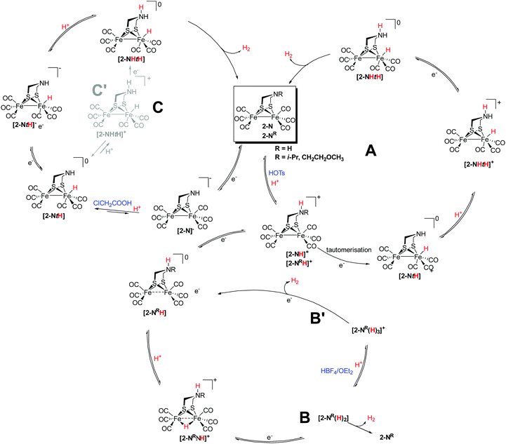 | ||
| Fig. 99 Catalytic pathways for the proton reduction by Fe2(adt)(CO)6 and Fe2(adtR)(CO)6 analogues with acids of varying strength. | ||
Notably, when utilizing weaker acids (e.g. CH3COOH), Fe2(adtR)(CO)6 models adopt a pathway similar to the PDT derivatives (Fig. 99 scheme C). Here the model must take up electrons before being protonated and the adjacent amine is not involved in the overall hydrogen formation mechanism. E.g., Fe2(adt)(CO)6 is protonated by ClCH2COOH (pKa = 15.3) at the metal centre (pKa = 17.1) only upon undergoing 1e− reduction at −1.60 V. There is also a possibility to establish a concerted proton electron transfer pathway resulting in [2-NHtH] from [2-NtH]+ (Fig. 99 scheme C′). However, this pathway has not been explored in detail and thus will not be further discussed.500
Underlining the control of acidic strength on the catalytic pathway, Fe2(adtR)(CO)6 (R = p-C6H4COOMe, 301)460 was shown to adopt two different pathways for the proton reduction depending on the strength of the utilized acid. In case of CF3COOH, the complexes follow an ECCE mechanism as the reduced state can be protonated twice. Subsequent reduction generates H2. Contrarily, with HOAc an EECC mechanism is observed. Herein, only the dianionic complex of the models is basic enough to be protonated by weak acids and consequently H2 is only released at very negative potentials.491 The catalytic efficiencies with CF3COOH (TON = 10.6) were shown to be larger than with HOAc (TON = 4).460 Similarly, in case of a missing suitable protonation site, it is justified that the double-reduced species is protonated generating H2via an EECC mechanism with weak acids. Hereby it can be ascertained that the weaker acid (HOAc) requires the Fe0Fe0 state for catalytic activity.134,190,192,195,466,481 Contrastingly, the presence of a stronger acid such as HOTf, HClO4 or HBF4·OEt2 leads to a CEEC mechanism.177,194,196,456,481
As discussed in Section 4.3, BDT models possess a metal site that is sufficiently electron deficient and hence readily undergo a 2e−-reduction yielding the Fe0Fe0 state. This state participates in the catalytic cycle, generating H2 from HOAc upon double-protonation following an EECC mechanism. However, with HOTs the monoanionic mono-protonated state formed undergoes another reduction resulting in dianionic state, which only then releases H2 and reforms the FeIFe0 state (Fig. 100).467,468
A similar observation was made for phosphorus-substituted model 64. In the absence any of acid, model 64 is reduced via a concerted two-electron process. Contrary, when HOTs is added, the double-reduced state undergoes two successive protonation steps to yield a dihydride. Herein, each iron was suggested to bind a hydride affording [64-2tH]. Upon release of H2, this state reverts back to FeIFeI. Another plausible route involves a one-electron reduction of [64-2tH] resulting in the monoanionic state with concomitant H2 evolution. The former pathway is considered to eliminate H2 at slower rates due to the larger spatial separation of the two hydrides in [64-2tH].503
Along this line, 170 catalyses the proton reduction via two different pathways from HOTs.
(1) Protonation of the reduced state leads to [170-H]. This protonation is followed by another reduction and protonation and results in [170-HH]. The thus obtained intermediate can now either directly release H2 by formation of 170 or undergo further reduction thereby releasing H2 from [170-HH]− resulting in 170−.239
(2) The naphthalene substituted imine model 302 herein follow a CECE mechanism to reduce protons from HOTs.251 The acid protonates the imino substituent, resulting in imine protonated state [302–H]+, which is reduced at slightly positive potential than the parent model 302 resulting in [302-NH]+. [302-NH]+ undergoes a second protonation followed by reduction to give [302-HNH]+ which releases H2.251 Notably, the pyrazine modified models 303229 reduce protons from HOAc wherein the aromatic ring nitrogen acts as internal site of protonation. The protonated state undergoes reduction followed by another protonation at the nitrogen. Reduction of the diprotonated state yields the Fe0Fe0 state, which evolves dihydrogen and closes the catalytic cycle.
Another example wherein the acid strength influences the proton reduction pathway is the tetranuclear model 164. When strong acids such as CX3COOH (X = Cl, F) were employed as the proton source, the dianionic state was rapidly protonated and releases H2. Contrarily, in the presence of the weaker acid CH2ClCOOH the mono-protonated dianionic state either undergoes a further two-electron reduction resulting in the [164]3− state, which on further reaction with two protons releases H2 from the [164-HH]2− (Fig. 101).235
The influence of the ring-substituents on different catalytic pathways for the proton reduction can be demonstrated by 163 and 162 in the presence of HBF4·OEt2. In case of 163, a direct protonation of the model is not observed and was explained by the interaction of the nitrogen lone-pair with the ring sulphur π-electrons. Thus, an EC mechanism for the proton reduction was proposed based on electrochemical data. In contrast, 162 reveals a protonation at the ring nitrogen. This protonation is followed by two 1e−-reduction steps leading to [Fe0Fe0N-NH]−, which then reacts back to the parent model upon liberating H2.234
6.6.2.1 Models with innocent ligands. To obtain an enhanced basicity at the metal centre and to avoid ligand protonation related complications, numerous models with innocent phosphine and carbene ligands have been designed (Section 4.7). These substituted models have more negative reduction potentials (Epc) than their corresponding hexacarbonyl complexes. Compensating this trend, their catalytic potentials (Ecat) are, however, often anodically shifted. Due to the increased basicity of the metal core, the models are readily protonated at the metal centre resulting in terminal hydrides or along the metal–metal bond yielding bridging hydrides.445 These protonated intermediates undergo facile reduction. Notably, 219pdt follows the CECE catalytic pathway involving the [219pdt-μH] state.153 The P(OMe)3 disubstituted complex and similar complexes follow a CE pathway for proton reduction.482,485
Notably, the bridgehead amine in Fe2(adtR)(CO)6−n(L)n (R = Ph, C3H6COOH L = PMe3) remains the favoured protonation site.151,191,210,455 However, the electrochemical activity of the hexacarbonyl and phosphine disubstituted complexes differ significantly. In case of unsubstituted models, the protonation exclusively occurs at the bridgehead nitrogen, while in diphosphine substituted models the direct protonation at the Fe–Fe bond is possible as well resulting in potential catalysis CECE pathways. Interestingly, PMe3 mono- and disubstituted analogues of 109 and 110, with n- and isobutyric acid N-substitutions, were reported to even use water as proton source and revealed catalytic activity under neutral conditions at approx. −2 V (Fig. 106).191
In the proposed catalytic enzymatic pathways, the terminal hydride state is of key relevance for the hydrogen development (Fig. 19–21). Nevertheless, this state is rarely observed for hexacarbonyl complexes. However, unsymmetric substitution patterns at the diiron centre, with electron donating ligand were shown to assist in achieving such terminal hydride (see Section 5.3). Barton and Rauchfuss investigated model 233pdt and found that addition of HBF4·OEt2 to a solution of 233pdt in DCM at 0 °C resulted in a terminal hydride state. Notably, this complex catalyses proton reduction at −1.49 V compared to −1.78 V for the bridging isomer.154 Furthermore, the catalytic cycle proceeds with a second protonation of the one-electron reduced terminal hydride species followed by the release of H2. Subsequent reduction at less negative potentials regenerates 233pdt. In contrast to the bridging hydride [233pdt-μH]+, the model [233pdt-tH]+ comprising a terminal hydride is capable of generating H2 with a TOF of 5 s−1 with HBF4·OEt2.154
Likewise, the adt counterpart, (233adt), was investigated for its catalytic activity in DCM using acids of different strengths (ClCH2COOH (pKa = 15.30), CF3COOH (pKa = 12.65) and HBF4·OEt2 (pKa > 2)) at 0 °C (Fig. 102).451 In all cases, the catalytic cycle begins with a protonation of the bridgehead amine, followed by an intramolecular proton transfer to the metal centre to afford [233adt-tH]2+. With ClCH2COOH, the cycle proceeds with the reduction of [233adt-tH]+ to afford [233pdt-tH] which upon protonation and another reduction releases H2.451,504 With stronger acids (e.g. HBF4·OEt2 or CF3COOH), the bridgehead amine of [233adt-tH]+ is protonated further and the reduction of the double-protonated species gives a [233adt-η2-(H)2]+ intermediate state. This state then returns to the FeIFeI state upon reductive loss of H2. Moreover, this study also highlights the catalytic importance of the terminal hydride states and shows that terminal-hydride species generate H2 much faster (TON 5000 s−1 at −1.49 V) as compared to the bridging congeners (TON = 20 at −1.72 V).451,504
Likewise, the phosphine and carbene substituted asymmetric model Fe2(pdt)(CO)4(κ2-IMe(CH2)2PPh2) (304) forms a terminal hydride at low temperature (−90 °C) with HBF4·OEt2. Notably, this terminal hydride is inaccessible at room temperature.450 It was suggested that catalysis proceeds via the bridging hydride intermediate. Other carbene-substituted models, which have been studied for proton reduction, also proceed with a CE mechanism for H2 formation, majorly proceeding via μ-H state with moderately strong acids (CF3COOH)197,363 as well with strong acids (HBF4·OEt2).291
6.6.2.2 Models with protonable ligands. Besides the protonation of the bridgehead amine in adt-subsite models, a basic residue can be also present at the additional coordinating ligands.152,505 Active site analogues having proton responsive ligands such as PNP, pyridine and bipyridine attracted interest and the pendant basic sites were anticipated to relay protons to the metal centre and aid the proton–hydride formation for efficient H2 release (Fig. 103).
Herein, 294Me undergoes N-ligand protonation upon protonation with HBF4·OEt2 in acetone. Remarkably, in DCM a tautomerism resulting in μ-H was observed.152 A similar proton migration was observed for Fe2(pdt)(CO)4(κ2-L) (305, L = (PhP(CH2)2NPh)2) with CX3SO3H (X = F, H) resulting in the catalytically active μ-H state.461 In 294R (R = Ph, Me), the pendant basic site is rendered free to take up additional protons after transfer of proton to the metal centre. Although proton transfer reactions to the metal centres are observed and cause an anodic shift of the catalytic potential. Yet, the rate constants for HER are low due to sluggish proton transfer and H2 release.352
Along this line, 306a–c with similar diphosphine ligands ((Ph2PCH2)2X, X = NCH3 (a), NCH2CF3 (b), CH2 (c)) was examined. The study displays the proton directing influence of the chelating ligand. In case of 306a, the amine was protonated with HBF4·OEt2, while in 306b a hydride bridging the Fe centres was observed. In contrast, in case of 306c which lacks an amine group, protonation at the bridging sulphur was detected.225 Thus, it seems that pendant basic sites are not the first choice for protonation and the sequence of protonation depends on strength of acid and the corresponding basic site in the mimic. This preference was also illustrated by 307a,b (Fe2(pdt)(CO)5(PPh2(CH2)nPy) (n = 0 (a), 1 (b)), wherein protonation with HOTf occurs primarily at the Fe–Fe bond and only thereafter at the N-pyridyl in the phosphine ligand.505 Also, it is to be noted that a secondary sphere protonation might not always be fruitful, e.g. while the PTA ligand (1,3,5-triaza-7-phosphaadamantane) is protonated, this protonation is catalytically not very relevant.302 Likewise, [Fe2(pdt)(CO)5(CN)]− (215) undergoes protonation with HOTs at the cyanide ligand but displayed no significant catalytic activity.153 In contrast, [Fe2(adt)(CO)5(CN)]− (308) was found to be catalytically active with HOAc (as well with Cl2CHCOOH). The detailed catalytic mechanism remains to be elucidated – however, the difference in catalytic activity of 215 and 308 could be reasoned by the involvement of bridgehead nitrogen.478
Notably, the unsymmetrical model [Fe2(pdt)(CO)4(CN)(PMe3)]− (214) exhibits proton reduction activity in the presence of acids (HOTs, H2SO4) at −1.4 V (−1.0 V vs. NHE). IR and 1H-NMR spectroscopic investigation revealed direct protonation of the Fe–Fe bond affording a bridging hydride. On further reaction with HOTs, protonation of the coordinated cyanide likewise occurs.150 The double-protonated species undergoes reduction resulting in mixed-valent state which heterolytically releases H2. Notably, no external protons were required to move the cycle forward from the [HFe1.52(pdt)(CO)4(CNH)(PMe3)] state. Thus, H2 was released upon intramolecular hydride transfer. In contrast, the direct congener, [219pdt-μH]+![[thin space (1/6-em)]](https://www.rsc.org/images/entities/char_2009.gif) 423,424 requires additional protons to slowly form H2. Moreover, [Fe2(pdt)(CO)4(P(OMe)3)(CN)]− (309) is protonated solely at the cyanide ligand by HOTs, while HBF4·OEt4 protonates the complex at the metal centre as well as the ligand. Yet, the model displayed no catalytic activity.153 These examples clearly demonstrate the control of reactivity via the ancillary ligand protonation and highlights that the catalytic activity is achieved through a crucial electronic balance around the metal centres and efficient proton relays from non-remote transferring basic sites.150,153
423,424 requires additional protons to slowly form H2. Moreover, [Fe2(pdt)(CO)4(P(OMe)3)(CN)]− (309) is protonated solely at the cyanide ligand by HOTs, while HBF4·OEt4 protonates the complex at the metal centre as well as the ligand. Yet, the model displayed no catalytic activity.153 These examples clearly demonstrate the control of reactivity via the ancillary ligand protonation and highlights that the catalytic activity is achieved through a crucial electronic balance around the metal centres and efficient proton relays from non-remote transferring basic sites.150,153
Evidently, for Fe2(bdt)(CO)6 the introduction of one or two pyridyl-appended phosphine ligands (PPy3) proved to be extremely beneficial. Not only does the pyridyl site act as a potential site of protonation, but also solubilizes the complex in aqueous conditions. Having achieved a precise balance of the increased electron density at the Fe centre from phosphine ligands and a proximal protonation site, the mimic displays a TOF = 1.8 × 10⁷ s−1 at −0.90 V vs. NHE for Fe2(bdt)(CO)5(PPy3) (310) and 2.7 × 10⁸ s−1 at −0.97 V vs. NHE for Fe2(bdt)(CO)4(PPy3)2 (311) with dilute H2SO4.506
6.6.2.3 Models with redox-active ligands. The active machinery of the enzyme comprises a cubic [4Fe–4S]-cluster attached via cysteinyl ligand to the [2Fe–2S]-core. Subsequently, surrogates for the cubic cluster were investigated. With an exception of the appended [4Fe–4S]-cluster to a [2Fe–2S]-model reported by Pickett et al.,416 no such elaborate artificial systems have been reported. Instead, mimics with smaller and less complicated redox active ligands such as bipyridyl,371,507 phenanthroline507 and phosphole493 have been designed.
Also, in the IMes-substituted pdt complex 248 the presence of the NHC ligand alters the general pathway of the proton reduction. Due to involvement of the IMes ligand, 248 undergoes two successive reduction steps and the first reduction takes place at the metal centre, while the second occurs at the ligand. Hence, it was proposed that 248 follows an EECC mechanism and thus is able to generate H2 from weak acids. Following this double-reduction, protonation at the Fe site forms [H–FeIIFeI]. This state undergoes a second protonation along with concomitant internal electron transfer regenerating a FeIFeI state along with H2 evolution.362 A similar proton reduction mechanism was noted for in the presence of a bipyridyl ligand in complex 312.371 Herein, the generated dianion is protonated by AcOH. In contrast, in the presence of strong acids such as HBF4·Et2O and HOTs, 312 displays different of proton reductions behaviour (Fig. 104). Due to the bipyridyl ligand, the electron density at the FeFe centre is significantly increased and the metal–metal bond is protonated by the stronger acids resulting in a bridging hydride state [312-μH]+. The reduced species [312-μH] is then protonated, followed by another electron and proton uptake resulting in [312-3H]+ which on reductive elimination gives H2. However, this pathway did not account for the catalytic peak observed at −1.7 V. Therefore, it was proposed that [312-HH] undergoes a single-electron reduction at this potential to yield [312-HH]−. This state is then converted to [312-3H] upon protonation which on releasing H2 forms the [312-μH] state.371 Hence, in the presence of strong acids either [312-μH]+ is the proton reduction catalyst and operates via a ECEC or [312-μH] following a CECE mechanism.
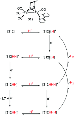 | ||
| Fig. 104 Catalytic pathway for HER from HBF4·OEt2 by 312.371 | ||
Another example wherein the ligand actively participates in the catalytic pathway is 313 modified with a phosphole. The complex displays three cathodic peaks – the first corresponds to the reduction of the ligand.493 The other two peaks are associated with two single-electron transfers to the diiron centre resulting into Fe0Fe0. According to spectroelectrochemical and theoretical modelling data, the catalytic cycle is initiated by a proton-coupled electron transfer and protonation occurring at −1.44 V. Here, protonation occurs at the Fe centre, leading to a mixed valent bridging hydride state [FeIIFeIμ-H] and another at the pyridine nitrogen of the ligand, which serves as the second protonation site. This double-protonated state undergoes a second two-electron reduction at −2.00 V accompanied by another ligand protonation (Fig. 105). This state was determined to be the resting state of the catalyst. The protonation and subsequent release of H2 from this state is the rate-determining step of the reaction. Hence, in this cycle the ligand serves as an electron reservoir and is involved in electron transfer to the metal centre. Additionally, 313 also catalyses proton reduction from dilute H2SO4 with an overpotential of 0.66 V and TOF 7 × 10⁴ s−1.493
In addition to the aforementioned models, many other mimics with redox active ligands such (bma = 2,3-bis(diphenylphosphino) maleic anhydride (bma), bpcd (4,5-bis(diphenylphosphino)-4-cyclopenten-1,3-dione)),311,313,314,508 fullerene,509 ferrocene312,349 and carborane bis-phosphine510 have been reported. However, involvement of these redox active moieties in catalytic mechanisms is either questionable or remains to be investigated in detail.
Based upon numerous detailed investigations of hydrogen evolution activity by diverse FeIFeI subsite models, the observed trends and generic behaviour can be summarised as follows:
• To enable H2 evolution from weak acids by hexacarbonyl models, these complexes are required to undergo reduction before being protonated.
• CO-substitution by stronger donating ligands such as phosphines or carbenes cause the diiron core to attain increased basicity. Thus, the catalytic cycle may begin via direct metal protonation.
• If there is an accessible basic site available in the model complex and an acid of suitable strength is employed, the catalytic cycle is facilitated by its protonation.
• Involvement of a redox active ligand can cause a double reduction to occur, i.e. one at the metal centre and another at the attached ligand before the model is protonated.
• In case of bidentate substitution at the Fe centre, the chelating isomer is reported to be more efficient for H2 generation than the symmetrically substituted bridging counterpart.
• pKa of acid used as the proton source determines the adopted catalytic pathway for H2 evolution and has profound influence on the catalytic activity and over-potentials.
Conclusively, extensive electrochemical analysis revealed various mechanisms (EECC, ECEC, ECCE, CECE, CEEC) and shed light on the involved iron centres redox behaviour within the H2 evolution activity in acidic media.
![[thin space (1/6-em)]](https://www.rsc.org/images/entities/char_2009.gif) :
:![[thin space (1/6-em)]](https://www.rsc.org/images/entities/char_2009.gif) CH3CN (5
CH3CN (5![[thin space (1/6-em)]](https://www.rsc.org/images/entities/char_2009.gif) :
:![[thin space (1/6-em)]](https://www.rsc.org/images/entities/char_2009.gif) 1) and were found to be catalytically active in presence of acetic acid at potential of ca. −1.6 V for 38 and ca. −1.8 V for 39 (vs. Ag+/0 0.01 M AgNO3).133
1) and were found to be catalytically active in presence of acetic acid at potential of ca. −1.6 V for 38 and ca. −1.8 V for 39 (vs. Ag+/0 0.01 M AgNO3).133
Attempts to achieve proton reduction catalysis in water are not limited to the modifications of the bridgehead substituents but have been extended to systems with modified ligands such as phosphines129,130 and peptides.306 Herein, tris(morpholino)phosphine (TMP) mono and disubstituted pdt models were tested for their proton reduction capabilities in different water:acetonitrile mixtures in the presence of AcOH.129 Both models proved to be electrocatalytically active operating via ECCE mechanism. Similar effects were reported for the introduction of a charged, quarternary ammonium-modified PNP ligand, enabling H2 production from HOAc in MeCN following the same mechanism.130 First, the reduced monoanion [FeIFe0]− is protonated resulting in [H-FeIIFeI] which on further protonation produces [HH-FeIIFeI]+. This species generates H2 upon reduction and the starting complex is regenerated. Notably, an increased catalytic activity (TONbridging = 14.4 in MeCN vs. 25.7 in MeCN![[thin space (1/6-em)]](https://www.rsc.org/images/entities/char_2009.gif) :
:![[thin space (1/6-em)]](https://www.rsc.org/images/entities/char_2009.gif) H2O (3
H2O (3![[thin space (1/6-em)]](https://www.rsc.org/images/entities/char_2009.gif) :
:![[thin space (1/6-em)]](https://www.rsc.org/images/entities/char_2009.gif) 2)) in mixed-solvent systems was reported for these complexes.129,130 Likewise, electrochemical properties of peptide modified models were significantly affected by presence of water and showed an up to 0.1 V anodic shift in their reduction potentials along with increased catalytic currents.306
2)) in mixed-solvent systems was reported for these complexes.129,130 Likewise, electrochemical properties of peptide modified models were significantly affected by presence of water and showed an up to 0.1 V anodic shift in their reduction potentials along with increased catalytic currents.306
Furthermore, adt-models 109 to 111 with carboxylic acid functionalities were synthesised and studied for their redox activity to benefit from the hydrogen bonding properties of their carboxylic acid residues. Cathodic scans displayed reduction peaks (ca. −1.6 V) which shift about 400 mV towards less negative potentials upon addition of one or two equivalents of HOTf suggesting protonation of nitrogen of the adt-bridge. Notably, complex 109 displayed an additional reduction peak, which was attributed to the proton coupled one-electron reduction process assisted by the carboxylic acid group.191
Furthermore, improved, second generation mimics were achieved upon replacing two carbonyls with PMe3 and were tested for their catalytic capabilities in water. Model 110PMe3 showed exclusive enhancement in reductive peak upon addition of one equivalent of water. However, in case of model 109PMe3 a small increasing peak at −1.7 V was observed, with subsequent addition of water which shifted to −1.5 V. Herein, the carboxylate group was involved in stabilising the protonated amine (Fig. 106) via hydrogen bonding. Distant orientation of carboxylate in 111PMe3 might, however limit this stabilisation and hence no comparable catalysis for this model was recorded.191
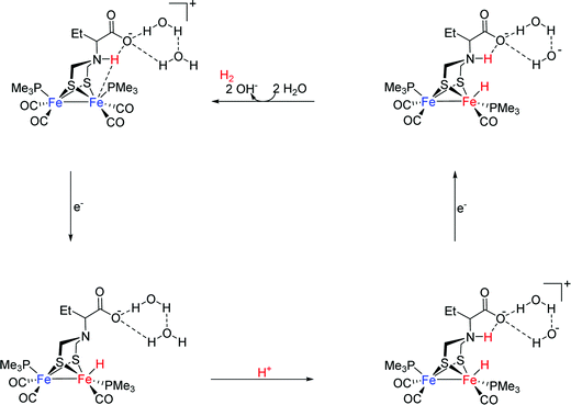 | ||
| Fig. 106 Proton reduction in H2O by model 110PMe3.191 | ||
6.7 Immobilisation of H-cluster models on electrodes
At the end of Section 4.2.3.1 we already mentioned that carboxylic acid functionalised [FeFe]-hydrogenase models are suitable for the attachment to surfaces. This is based on their reactivity towards amines that might be covalently bound to e.g. glassy carbon or fluorine doped tin oxide (FTO) electrodes, forming amides.141 This general concept to attach a homogeneous catalyst to electrode surfaces to generate immobilised systems was utilised by several groups.142,515,516 Interestingly the results are diverse. A gold or carbon immobilised pdt-model and a FTO immobilised bdt-model catalyse proton reduction from HBF4·Et2O acidic and chloroacetic acid acidic acetonitrile solutions, respectively but are rapidly inactivated by the loss of carbonyl ligands, catalyst leaching or hydrolysis under these conditions.515,516 Conversely, no catalytic proton reduction was found for an o-xyldt-model that was immobilised via a carbon surface bound p-tolylformamide.142 Other immobilisation techniques include formation of triazoles via Cu(I)-catalysed Huisgen addition or formation of an Au–S bond via thiols.517–519 Latter includes a pdt-like model that comprises a –PH2(CH2)2SH ligand for the attachment and is therefore the only surface attached model that is not bound via the bridging disulphide. Interestingly, thus study revealed that the parent compound 314 is inactive regarding proton reduction in solution, while its immobilised counterpart shows catalytic proton reduction upon addition of acetic acid. This phenomenon was explained by the inability of 314 to undergo a reduction process to a Fe0FeI or Fe0Fe0 species, which was however shown to be at −1.87 V and −2.24 V vs. Fc0/+, respectively by Liu et al. in 2009215 and is also visible in the respective cyclic voltammograms in the works by Darensbourg and coworkers.518,519 Four years later, Zaffaroni et al. described a 160 mV anodically shifted operational overpotential for the FTO immobilised bdt-model compared to its homogenous counterpart.516 This kinetic effect due to the binding of an homogeneous catalyst to an electrode surface might have been the reason for the observation of Darensbourg and coworkers as well. In 2017, Dey and coworkers reported on the first adt-like model that was covalently linked to a graphite electrode surface via Huisgen addition (Fig. 107). In the opposite to the systems described above, this system is reported to be stable for several hours under turn-over conditions and shows a high faradaic yield of 90.7% for H2 evolution after 1200 s.517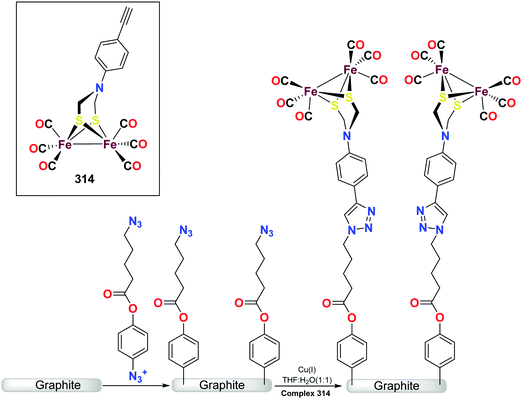 | ||
| Fig. 107 Schematic presentation of covalent attachment for the [FeFe]-hydrogenase model 314 on modified graphite surfaces. Reproduced from ref. 517 with permission from The Royal Society of Chemistry. | ||
6.8 Perspective for the electrocatalytic proton reduction by H-cluster models
The electrochemical investigations coupled with theoretical calculations as well as spectroscopic investigations significantly contributed to describe different pathways for proton reduction by the [FeFe]-hydrogenase models. It has to be noted that the strength of the acid employed significantly affects the proton reduction pathways. The models possessing intrinsic bases, such as the bridgehead amine, conduct protonation at milder potentials in comparison to the models lacking such sites. Furthermore, the donating capabilities of the ligands also influences the attainable redox states in the proton reduction catalytic cycles. When the carbonyl ligands are substituted by donor ligands, the reduction potential of the models display cathodic shifts. Accompanying this cathodic shift, the protonation is facilitated due to increased electron density at the metallic centre. A few terminal hydride bearing species have been observed and it has been ascertained that the terminal hydride species are more efficient catalysts in comparison to the thermodynamically more stable bridging hydride state.Even after the aforementioned advances, challenges to develop systems with matching efficiencies to the natural system exists. Unlike the enzyme, the majority of the models are catalytically active in organic solvents and utilize organic acids to generate H2. They do not follow the bio-catalytic pathway. Nonetheless the electrochemical studies on the synthetic systems impressively uncovered the interplay between the basicity and reduction potentials of the models and shed light on the hydrogen generation mechanism.
VII Photocatalytic proton reduction by H-cluster models
The development of artificial systems that efficiently mimic the natural photosynthetic pathways and allow for a conversion of solar energy into storable and useable forms has gained major attention.520–522 Due to their unprecedented H2 generation capacity, [FeFe]-hydrogenases are considered a suitable choice for engineering sustainable photocatalytic machineries although these natural enzymes are not photocatalytically active by themselves. Nonetheless, the need to develop renewable alternatives for H2 production, drives the hydrogenase community to take profound interest in designing such systems. Numerous models of the [FeFe]-hydrogenase have been previously described, which in conjunction with suitable light harvesting systems could form promising systems for light-to-fuel conversion technologies (Fig. 108).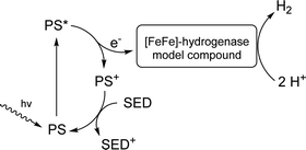 | ||
| Fig. 108 Potential mechanism for the photosensitised hydrogen evolution. PS = photosensitizer, SED = sacrificial electron donor. | ||
Photocatalytic hydrogen producing assemblies are commonly comprised of a photosensitizer (PS) capable of harvesting light along with a proton reducing catalyst, a sacrificial electron donor, which is capable of restoring the actual redox state of the sensitizer, and a proton donor. For diiron-complexes in particular, a potential mechanism for the H2 formation involves photon absorption by the sensitizer (organic moieties, semiconductors), followed by an electron transfer from the photoexcited sensitizer to the diiron catalytic centre. Subsequently, protonation of the reduced catalyst takes place. This process is followed by another electron transfer to the bimetallic catalytic centre resulting in H2 formation, thereby closing the cycle.521,523
A variety of architectures with different photocatalytic abilities have been designed and will be discussed herein. These systems either vary in the choice of photosensitizer or the proton reduction centre. In general, two approaches were adopted to link photosensitizers to the active site models. In the first strategy, attachment of the chromophore to the bridgehead atom through chemical modifications was performed. Furthermore, the photo-sensitive moiety can be directly linked to the diiron site.
7.1 Covalent attachment of photosensitizers to H-cluster models
Following these reports, Song et al. incorporated a tetraphenylporphyrin group (TPP) on the bridgehead nitrogen of Fe2(adtR)(CO)6 (R = p-C6H4CHO), via covalent bonding resulting in 317.526 With the improved light absorbance of TPP and the longer excited state lifetime, it was anticipated to be favourable for the electron transfer processes towards the diiron site. Indeed, the electron was shown to be readily transferred from the photoexcited sensitizer to the diiron center.526
Subsequently, a three-component system, 318 built from Fe2(adtR)(CO)6, a Re-photosensitizer and ferrocene was established. Here, the catalytic site and the sensitizer were separated by an ethynyl linker that provided appropriate separation for fast electron transfer without electron recombination at the sensitizer. Utilizing ascorbic acid as proton source and as the sacrificial electron donor, the system displayed a TON of 0.35.527
Despite of their obvious potentials noble metal-based photosensitizers are not particularly desirable due to their expensive production and involvement in complex deteriorating pathways. As a noble metal free alternative, a zinc tetraphenylporphyrin (ZnTPP) unit linked to ADT via the amine bridge (319) to achieve considerable photochemical HER activity. As expected, significant fluorescence quenching was observed suggesting an intramolecular electron transfer from ZnTPP to the diiron centre. However, the exact electron transfer pathway for such systems remains elusive.188 Along this line, complex 320 was established and investigated for its H2 production capability. Interestingly, the complex 320 revealed a faster electron transfer from the TPP moiety to the diiron unit as compared with the covalently linked systems. The newly established complex also allowed to overcome charge recombination required for fast catalytic conversion processes but only showed low turnover numbers. This behaviour was ascribed to the photo instability of the catalyst.528 Along this modification strategy, model 181 was reported comprising a covalently attached ZnTPP/naphthalene unit. A thermodynamically favourable electron transfer from the sensitizer to the catalytic site was suggested based on electrochemical investigations with the first reduction potential of the mimic being less negative than the oxidation potential of the photoexcited ZnTPP unit (−1.65 V vs. −1.74 V).251 In addition, Wasielewski and coworkers investigated the reactivity of 321a–c. It was observed that employing a second electron donor in these systems is beneficial, increasing the lifetime of the reduced diiron centre and facilitates the catalytic activity. Likewise, upon extending the linker length between the photosensitizer and the catalytic site, the electron transfer to the diiron centres is favoured and the electron recombination time period increases by a factor of 7.5. Hence, only 321c displayed significant photocatalytic activity with the additional phenyl group disfavouring quenching due to efficient energy transfer to the ferrocene moiety. However, the observed photocatalytic activity is limited by degradation of the diiron centre upon irradiation (Fig. 110).252
In a comparable approach, complex 323 was prepared. Herein, the platinum(II)-polypyridyl alkynyl sensitizer is attached via an isonitrile group to the Fe2(pdt)(CO)5 moiety.530 The resulting system displayed long-lived MLCT states. However, the important reduction of the FeIFe0 state is thermodynamically unfeasible and thus explains the overall low catalytic efficiency.530 Furthermore, a series of cyanide ligand modified hydrogenase mimics was reported (324a–c, Fig. 112) using rhenium photosensitizers as prospective catalyst systems but revealed comparable problems.531
Kluwer and coworkers reported a macromolecular system carrying two photosensitizers covalently attached to the Fe centres via phosphine groups [Fe2(pdt)(CO)4{PPh2(4-py)}2] and modified this complex with zinc(II)porphyrin chromophores 325 (Fig. 113). However, this design strategy proved to be unsatisfactory as only two turnovers per catalyst under optimized conditions were observed.532 Rauchfuss and coworkers reported on the photocatalytic activity of [219pdt-μH]+ and [231pdt-μH]+ in the presence of ferrocene as recyclable electron donor. Strikingly, this system was shown to overcome the limitation of the otherwise required high reduction potentials for the hexacarbonyl systems (−1.33, −1.4 V vs. −1.66 V for 20).533
7.2 Photocatalytic multi-component systems
Although a significant number of reports exists for photosensitizer-bound proton reduction sites, all systems display severe limitations and none of them allows for sufficient H2 generation. An alternative strategy to build photocatalytic hydrogenase mimics is the use of multicomponent systems i.e. consisting of unlinked photosensitizers and H2-formation sites. One of the early reports in this field describes the incorporation of quantum dots (QDs) as potential photosensitizers. Quantum dots possess superior visible light absorption abilities and importantly, are stable under aqueous conditions. Notably, 3-mercaptopropionic stabilised nanocrystal quantum dots in the presence of a [2Fe–2S]-cluster and ascorbic acid revealed promising turnover numbers and turnover frequencies of up to 505 and 50 h−1 within 10 h of illumination.534Likewise, the utilization of Ru-based light harvesters was suggested as a potential replacement for the biologically relevant [4Fe–4S]-clusters in an artificial system. Due to its similar reduction potential compared to that of the diiron dithiolate hexacarbonyl complex, [Ru(bpy)3]2+ was proposed as an efficient photo sensitizer. Upon adopting the diethyldithiocarbamate anion (dtc−) as an electron donor, the challenge of reverse electron transfer was surmounted, as the electron transfer generated thiyl radicals, from the dithiolate anions, which underwent quick dimerization and thus extend the excited state lifetime of [Ru(bpy)3]+. Still, this system suffered from photo-bleaching and protonation of the anionic quencher.535 Multiple phosphine variants of pdt (20) and adtBn (91) models were subsequently investigated utilizing ascorbic acid and [Ru(bpy)3]2+ and achieved a maximal TON of 4.3 under optimum conditions.536
Especially the chlorine substituted bdt model 150 is a suitable candidate for studying the photochemical H2 production due to its less negative reduction potential in combination with its high stability and capability to undergo reversible reductions. Along this line, a composite system consisting of this particular mimic, [Ru(bpy)3]2+ as photosensitizer and ascorbic acid as proton and electron donor was subsequently investigated and revealed a TON of 200 along with a TOF of 2.7 min−1 in DMF/H2O solutions at pH of 5.5.537
7.3 Confinement of the photocatalytic system
Although chemists have succeeded in designing active site analogues, in which the photosensitizer is attached to the catalytic site, yet such systems are far away from any application as these systems are limited in stability, solubility and H2 generation. An alternative strategy to achieve an appreciable activity similar to that of the natural system, the skilful alteration of the secondary coordination sphere of the catalyst was anticipated to tune the solubility and stability.Notably, the microenvironment influences the photocatalytic performance considerably – to this end, catalytic diiron models were either embedded in a polymeric scaffold or incorporated into nanomaterials, generating improved heterogeneous proton reduction assemblies that will be described in the following sections.165,187,511,538–541
7.3.1.1 Synthetic polymers. Polymers are one potential support to incorporate the catalytic centre and photosensitizer as they allow to shape the environment of the catalyst and allow for the encapsulation of additional substrates. For instance, the sulphonate modified adt-model Fe2(adtR)(CO)6 (326, R = p-C6H4SO3−Na+) along with Ru-polypyridine based photosensitizers were grafted onto a phospholipid membrane (DOPC 1,2-dioleoyl-sn-glycero-3-phosphocholine). This self-assembled system displayed a significantly increased photocatalytic activity under acidic conditions (pH 2.6) in comparison to the non-immobilised models. A reason for this performance enhancement was found in the close proximity of the relay groups involved in electron transfer processes. The highest photocatalytic activity was reported utilizing ascorbic acid with a TON of 57.
In addition, activity tests for catalysts embedded in lipids were conducted as well and an activity enhancement was observed with lipid layers with higher order such as DOPC and DMPC (1,2-dimyristoyl-sn-glycero-3-phosphocholine). However, the activity of these membrane assemblies is yet still limited by photosensitizer degradation.542
Furthermore, a series of macro models was established upon reacting Fe2S2(CO)6 with a Fréchet-type dendron in THF (Fig. 114). The resulting dendrites were likewise studied for their photocatalytic activity in the presence of [Ir(ppy)2(bpy)]PF6 (ppy = 2-phenylpyridine, bpy = 2,2′-bipyridine) as the photosensitizer and triethylamine as the sacrificial electron donor in water/acetone (1![[thin space (1/6-em)]](https://www.rsc.org/images/entities/char_2009.gif) :
:![[thin space (1/6-em)]](https://www.rsc.org/images/entities/char_2009.gif) 9) mixtures. Notably, the largest dendrimer (Fig. 114, Hy-G4) displayed a high TON of 22
9) mixtures. Notably, the largest dendrimer (Fig. 114, Hy-G4) displayed a high TON of 22![[thin space (1/6-em)]](https://www.rsc.org/images/entities/char_2009.gif) 200 with a TOF of 7240 h−1. The hydrophobic environment created by the dendrite around the catalytic site was herein suggested to allow for a close interaction of the neutral sensitizer and the charged photosensitizer and reasoned to be origin of the high activity.511
200 with a TOF of 7240 h−1. The hydrophobic environment created by the dendrite around the catalytic site was herein suggested to allow for a close interaction of the neutral sensitizer and the charged photosensitizer and reasoned to be origin of the high activity.511
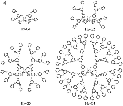 | ||
| Fig. 114 Structures of dendrimer based [2Fe]H mimics. Reprinted from ref. 511 with permission from John Wiley and Sons, Copyright 2013. | ||
Furthermore, a three-component assembly – branched polyethyleneimine functionalised with an isocyanide ligand modified pdt mimic (327), MPA–CdSe quantum dots and ascorbic acid – was shown to be photocatalytically active in water over a broad pH range and provided high TON values of up to 10![[thin space (1/6-em)]](https://www.rsc.org/images/entities/char_2009.gif) 600 at neutral pH. Herein, incorporating MPA–CdSe QDs into the systems was found to be beneficial as these are easily dispersed in water and have intense photon absorbing properties. Likewise, the branched polymer has numerous amine groups, which are capable of binding to the specific mimic and potentially act as proton relays to the catalytic site. Most important, the polymer stabilizes the CdSe quantum dots against aggregation and thus contributes significantly to the high activity and stability.538
600 at neutral pH. Herein, incorporating MPA–CdSe QDs into the systems was found to be beneficial as these are easily dispersed in water and have intense photon absorbing properties. Likewise, the branched polymer has numerous amine groups, which are capable of binding to the specific mimic and potentially act as proton relays to the catalytic site. Most important, the polymer stabilizes the CdSe quantum dots against aggregation and thus contributes significantly to the high activity and stability.538
A breakthrough study for the photocatalytic H2 production was reported on systems containing an isocyanide PDT model which was attached to polyacrylic acid (PAA) (Fig. 115).165 Here, the hydrophilic PAA assists in the solubilisation of the otherwise insoluble catalyst system in water and TONs of up to 27![[thin space (1/6-em)]](https://www.rsc.org/images/entities/char_2009.gif) 135 and TOF 3.6 s−1 were obtained at pH 4. Notably, due to the surrounding PAA, the 2-mercaptobenzoic acid (MAA) stabilized CdSe quantum dots (QDs) were protected from aggregation. Furthermore, the polymer brings the sensitizer and the catalytic site in close proximity to each other and thereby allows for an enhanced electron transfer.165
135 and TOF 3.6 s−1 were obtained at pH 4. Notably, due to the surrounding PAA, the 2-mercaptobenzoic acid (MAA) stabilized CdSe quantum dots (QDs) were protected from aggregation. Furthermore, the polymer brings the sensitizer and the catalytic site in close proximity to each other and thereby allows for an enhanced electron transfer.165
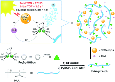 | ||
| Fig. 115 Synthetic pathway towards modified pdt and representation of catalytic activity. Reprinted from ref. 165 with permission from John Wiley and Sons, Copyright 2013. | ||
7.3.1.2 Peptides and proteins. As an alternative to synthetic polymers, a combination of active site models with biological scaffolds was used to tune the secondary coordination sphere and with it to optimize catalyst solubility and activity – for example, 219pdt was encapsulated in a low molecular weight hydrogelator (Fmoc–Leu–Leu). This secondary sphere prevents the polymerization of 219pdt and is hence positively affecting its stability (Fig. 116). Notably, a network of H-bonds was observed when the model is implemented within the gel confirming a significantly higher stability in aqueous media.512
In addition, the covalent attachment of modified Fe2(pdt)(CO)6 to the cavity of a β-barrel protein apo-nitrobindin (apo-NB) was reported. Model 328 bearing a maleimide group covalently binds to cysteine residue (Q96C mutant) within the protein and this assembly along with [Ru(bpy)3]2+ and ascorbate in 50 mM Tris/HCl at pH 4.0 and 25 °C allowed for the generation of hydrogen (TON up to 130 for 6 h).543
Furthermore, employing cytochrome C which functions as native electron relay in the natural system, an artificial metalloenzyme was constructed via attaching the [2Fe–2S]-site to the CXXC motif (Cys14, Cys17) of the apo-enzyme, giving a Fe2(S-Cys)2(CO)6 unit. Subsequently, this synthetic machinery was studied for photocatalytic H2 development using [Ru(bpy)3]2+ and ascorbic acid. The assembly in aqueous media generates H2 with a TON of 80 over 2 h at pH 4.7.544 To further investigate the electron transfer process between the photosensitizer and the catalytic centre, a more elaborate system was designed, wherein the ruthenium sensitizer was coordinated to the adjacent histidine residue (CXXCH sequence) of cytochrome C556. After 2 h of irradiation, catalytic activity for the photo-induced hydrogen development with a TON of 9 at pH 8.5 was observed.545
Although Ru-based photosensitisers and pdt-derived model 23 were non-covalently encapsulated in a hydrophobic (horse spleen) apo-ferritin cavity, this confinement enhances the solubility of the components along with providing a close proximity for an improved electron exchange. However, the highest recorded TON for such a system was 5 and the photosensitizer [Ru(bpy)2(dpqp)]2+ was found to limit the activity of the system.546 In contrast, if the sensitizer [Ru(bpy)3]2+ was not incorporated in the ferritin pocket and rather homogenised in solution, a TON of 31 was reported.547
Recently, Li and coworkers reported self-assembled ovalbumin (OVA) nanogels which incorporate 20. This incorporation improved the photocatalytic efficiency for H2 evolution in acid aqueous solution by 15% under optimized conditions. It is important to mention that acid induced structural changes (unfolding of α-helix to β-sheets) within the nanogels contribute massively to the overall performance.54820 was likewise linked to an artificial dithiol amino acid, which was in turn incorporated into an alpha helical peptide scaffold. This assembly, using [Ru(bpy)3]2+ and ascorbate generates H2 with a TON of 84 in acidic aqueous solutions under light irradiation.513
7.3.1.3 Polysaccharides and oligosaccharides. To imitate the protein cavity of hydrogenases and to favour catalytically active intermediates Darensbourg and coworkers incorporated 326 into a β-dextrin. The anionic sulfonate group herein assists in the dissolution of the complex within dextrin. Notably, upon protonation with HOAc in water, the system displayed an electrocatalytic peak at −1.4 V vs. Ag/AgCl. However, 13C-NMR studies revealed that the encapsulation of the model into dextrin is rather dynamic and not sufficient enough to artificially reproduce the natural protein environment.131 Also, an improved version of this model with various phosphine ligands (PTA, PMe3, P(OMe)3, PPh3) was reported, but these models display rather unsatisfactory reduction properties.189 Following this research Sun et al. studied the photocatalysis of this encapsulated system using Rose Bengal as well as Eosin Y as sensitizers.549 These organic sensitizers also participated in the host–guest interaction with β- and γ-dextrins and allowed for a faster electron transfer processes from the photosensitizer to the diiron centre. This improved electron transfer resulted in an enhanced quantum efficiency for the system.
In another attempt, chitosan – a naturally occurring polysaccharide – was used to greatly improve the solubility and photo dependent H2 producing ability of 91 in the presence of CdTe quantum dots capped with 3-mercaptopropionic acid (MPA–CdTe QDs) and ascorbic acid. Along this line, chitosan can be converted into a multi cationic system when its surface amine and phenolic groups are exposed to acidic conditions. These cationic species show great affinity for the negatively charged MPA–CdTe QDs and in return favour the electron transfer process to the imbedded catalyst. Here, the confined environment provided by chitosan allows for a close interaction of the catalyst, photosensitizer and the proton donor and results in an unprecedented TON of up to 52![[thin space (1/6-em)]](https://www.rsc.org/images/entities/char_2009.gif) 800 and a TOF of 1.40 s−1 Seemingly, a modified environment to increase the stability of the catalyst and to overcome limitations of the non-modified systems is of utmost importance.539
800 and a TOF of 1.40 s−1 Seemingly, a modified environment to increase the stability of the catalyst and to overcome limitations of the non-modified systems is of utmost importance.539
Along this line of modification, 149 displayed reasonable catalytic activity (TON 117) in water under basic conditions (at pH 10.5) upon incorporation into sodium dodecyl sulphate (SDS) micelles. Eosin Y was herein utilized as a photosensitizer and triethyl amine as electron donor. In the absence of the SDS micelles, the catalytic activity of the complex is lowered to one fourth of the maximum activity.514
Utilizing the same conceptual approach, 330 loaded onto the zirconium terephthalic acid MOF UiO-66(Zr) revealed an improved photocatalytic activity in presence of ascorbic acid and [Ru(bpy)3]2+ as compared to the individual components and likewise circumvents the undesired charge recombination.553 As studies on this system revealed a potential clogging of channels by ion pairs generated by reduction of catalyst, 159 was loaded onto e.g. the chromium MOF MIL-101 which revealed enlarged pore sizes of 29–34 Å as compared to UiO-66(Zr) with 8–11 Å. Subsequent photochemical investigation with different catalyst to MOF ratios revealed that H2 production is proportional to catalyst loading in the MOF thus following first order kinetics.554
In addition, bis(2-phenylpyridine)(2,2′-bipyridine)iridium(III) chromophores were introduced on a diiron hydrogenase mimic by click-chemistry. The modified chromophores were then incorporated into a K+-exchanged molecular sieve, MCM-41. When examined for their photocatalytic activity in presence of triethylamine (TEA), CH3CN and H2O (9![[thin space (1/6-em)]](https://www.rsc.org/images/entities/char_2009.gif) :
:![[thin space (1/6-em)]](https://www.rsc.org/images/entities/char_2009.gif) 1) at pH 10, the composite enabled the formation of 11.8 μL H2 with 5.5 mg composite and a loading 19.1 μmol g−1. The enhanced activity of the incorporated system was attributed to the complex stabilisation by the molecular sieve.555
1) at pH 10, the composite enabled the formation of 11.8 μL H2 with 5.5 mg composite and a loading 19.1 μmol g−1. The enhanced activity of the incorporated system was attributed to the complex stabilisation by the molecular sieve.555
7.4 Attachment of the photocatalytic system to nanoparticles
To overcome the limitations of high cost and insufficient stability associated with above mentioned complexes, semi-conductors can likewise be employed as photosensitizers. Prerequisites of an ideal semiconductor are a large band gap possessing a conduction band with a redox potential capable of reducing protons as well as good water solubility. In that sense, two sub-site models, 90 and 331 were incorporated onto the surface of ZnS. ZnS is a noble metal-free and highly photoactive material. However, it suffers from a rapid recombination of the generated electron/holes pairs.556,557 To this end, when the diiron subsite models are adsorbed on the ZnS surface and triethanolamine (TEOA) was used as the electron donor, photocatalytic experiments showed a TON of 3400 and 4950 for C1&ZnS and C2&ZnS in DMF![[thin space (1/6-em)]](https://www.rsc.org/images/entities/char_2009.gif) :
:![[thin space (1/6-em)]](https://www.rsc.org/images/entities/char_2009.gif) H2O system (9
H2O system (9![[thin space (1/6-em)]](https://www.rsc.org/images/entities/char_2009.gif) :
:![[thin space (1/6-em)]](https://www.rsc.org/images/entities/char_2009.gif) 1).187 Similarly, aniline functionalised 332 adsorbed on ZnS nanoparticles was stable for up to 38 h of irradiation and displayed a TON of 2607 and initial TOF of 100 h−1 in presence of ascorbic acid at pH 4.6.540
1).187 Similarly, aniline functionalised 332 adsorbed on ZnS nanoparticles was stable for up to 38 h of irradiation and displayed a TON of 2607 and initial TOF of 100 h−1 in presence of ascorbic acid at pH 4.6.540
Furthermore, 159 was attached to the surface of an oligoethylene glycol shell modified ZnO along with the natural pigment betanin as the light harvester. The modified ZnO nanocrystals revealed an extended excited electron lifetime in the conduction band and showed enhanced charge separation as well as accumulation of reactive electrons for the photocatalytic process. With trifluoroacetic the system displayed a TON of 11 and stability up to 6 h. Under otherwise unmodified catalyst conditions, solely a stability of up to 2 h was observed.541 Furthermore, with modified nano cathodes i.e. cross-linked indium phosphide nanocrystal array grafted with Fe2S2(CO)6 (1), a photoelectrochemical efficiency of more than 60% was witnessed at −0.9 V vs. SCE (Fig. 117).558
7.5 Tailoring the photocatalytic proton reduction by H-cluster models
These studies report significant developments in tailoring artificial scaffolds for the light-dependent hydrogen generation and support the crucial role of the microenvironment in tuning the properties of these systems. Also, remarkable progress was achieved in obtaining functional systems under aqueous conditions or systems which avoid the use of noble metals for hydrogen generation. Presently, investigations of mechanistic pathways are under progress to provide detailed explanation of the functioning of these systems. Nonetheless, to match the activities of the natural systems, further modulations are required to generate systems which are suitable for incorporation in technological devices.VIII Conclusion
In conclusion, we herein highlight the development in the [FeFe]-hydrogenase research over the last decades. While initially, structural alterations of mimics along with spectroscopic investigations were performed to understand the natural enzyme, pinpoint its various states and relate them to electronic and structural changes in the active centre, later investigations focused mainly on the electrochemical properties of such systems with the aim to find suitable proton reduction catalysts. Recently, the understanding of the enzymatic properties as well as direct alteration of the entire enzyme became the focus of many investigations due to the possibility to implement artificial synthetic mimics into the natural environment. However, concerning the enzyme and its functional mechanism, important questions remain to be answered. Up to date, no conclusive evidence was presented allowing for the determination of an exact consecutive sequence of proton/electron transfer events in the catalytic cycle. Hence, several plausible catalytic cycles were presented, and future investigations will have to provide evidence in favour of one over the others. Furthermore, understanding of the functional role of the enzyme backbone surrounding the H-cluster is deficient, e.g. reflected in the potential role of a second substrate/proton channel in the native enzymes. Along this line, artificial surroundings of the H-cluster such as polymers are expected to be a growing field of interest. In general, however, we expect hydrogenase-research to become more applications oriented. For example, enzymes, entire cells or well-designed mimics may serve as efficient catalysts in energy storage applications such as fuel cells or electrolysers for water splitting. Furthermore, a functional coupling to sustainable energy supplies such as photovoltaics appears to be a promising approach. With these ideas in mind, we believe that hydrogenase research is and will be a vivid field of enzymatic research that is now on the verge of advancing to the exploration of potential technological applications. At the same time smart ideas are demanded to advance to the level of understanding further to a yet unprecedent detail. We hope that this review gives the interested reader an overview on this topic and allows him to find hitherto unresolved research questions to fuel this interesting research with novel ideas worth pursuing in the near future.List of abbreviations
| ap | Apical |
| ba | Basal |
| BSA | Bovine serum albumin |
| ENDOR | Electron nuclear double resonance |
| E pa | Anodic peak potential |
| E pc | Cathodic peak potential |
| EPR | Electron paramagnetic resonance |
| Fed | Distal (or rotated) iron atom in [2Fe]H referred to [4Fe]H |
| Fep | Proximal (or unrotated) iron atom [2Fe]H referred to [4Fe]H |
| FTO | Fluorine doped tin oxide |
| HER | Hydrogen evolution reaction |
| hfc | Hyperfine coupling |
| HYSCORE | Hyperfine sublevel correlation |
| IR | infrared |
| MLCT | Metal-to-ligand charge transfer |
| NRVS | Nuclear resonance vibrational spectroscopy |
| NHE | Normal hydrogen electrode |
| OCP | Open circuit potential |
| PCET | Proton-coupled electron transfer |
| PET | Photon-driven electron transfer |
| PS | Photosensitizer |
| PTP | Proton transfer pathway |
| QDs | Quantum dots |
| r.t. | Room temperature |
| SDM | Site directed mutagenesis |
| SHE | Standard hydrogen electrode |
| SEC | Spectroelectrochemistry |
| TOF | Turnover frequency |
| TON | Turnover number |
| WT | Wild type |
| XAE | X-ray absorption and emission |
| XRD | X-ray diffraction |
Proteins
| HydG | Maturase protein |
| HydE | Maturase protein |
| HydF | Maturase protein |
| apo-HydA | Hydrogenase lacking [2Fe]H |
| HydA | Maturated hydrogenase |
| HydS | Sensory hydrogenase |
| CrHydA1(XDT) | [FeFe]-hydrogenase from C. reinhardtii with an xdt bridged [2Fe]H |
| CpI | Hydrogenase I from C. pasteurianum |
| CpII | Hydrogenase II from C. pasteurianum |
| DdH | Hydrogenase from D. desulfuricans |
Compounds and groups
| bda | benzylideneacetone/(E)-4-phenylbut-3-ene-2-one |
| BIAN-R | Bis(arylimino)acenaphthene |
| Bn | Benzyl |
| DCM | Dichloromethane |
| DDQ | 2,3-Dichloro-5,6-dicyano-1,4-benzoquinone |
| DHG | Dehydroglycine |
| DMF | Dimethylformamide |
| DMPC | 1,2-Dimyristoyl-sn-glycero-3-phosphatidylcholine |
| DOPC | 1,2-Dioleoyl-sn-glycero-3-phosphatidylcholine |
| dtc− | Diethyldithiocarbamate |
| Fc | Ferrocene |
| Fc* | Decamethylferrocene |
| Fmoc | Fluorenylmethoxycarbonyl protecting group |
| hmds | Hexamethyldisilazide |
| HOAc | Acetic acid |
| HOTf | Trifluoromethanesulfonic acid |
| HOTs | p-Toluenesulfonic acid |
| HOB | Hydroxybenzyl |
| H4folate | Tetrahydrofolate |
| MAA | 2-Mercaptobenzoic acid |
| MeCN | Acetonitrile |
| MOF | metal–organic framework |
| MPA | 3-Mercaptopropionic acid |
| NaDT | Sodium dithionite |
| NB | Nitrobindin |
| NMI | Naphthalene monoimide |
| OVA | Ovalbumin |
| PAA | Polyacrylic acid |
| PLP | Pyridoxal phosphate |
| POEGMA | Poly(oligo(ethyleneglycol)methyl ether methacrylate) |
| ppy | 2-Phenylpyridine |
| py | Pyridyl |
| SAM | S-Adenosyl-L-methionine |
| SDS | Sodium dodecyl sulphate |
| TEA | Triethylamine |
| TEOA | Triethanolamine |
| TFA | Trifluoroacetic acid |
| THF | Tetrahydrofuran |
| TMP | Tris(morpholino)phosphine |
| tol | Methylphenyl |
| 5′-DA˙ | 5′-Deoxyadenosyl radical |
| 5′-DAH | 5′-Deoxyadenosine |
| [BArF]− | tetrakis(3,5-bis(trifluoromethyl)phenyl)borane or tetra(pentafluorophenyl)borane |
Dithiolates and derivatives
| adSe | Bis(selenidomethyl)amine |
| adt | Bis(sulfidomethyl)amine |
| adtBH3 | Borane bis(sulfidomethyl)amine |
| adtBn | N-Benzylbis(sulfidomethyl)amine |
| adtMe | N-Methylbis(sulfidomethyl)amine |
| adtMeBH3 | Borane N-methylbis(sulfidomethyl)amine |
| adtn-propyl | N-Propylbis(sulfidomethyl)amine |
| adtSMe | N-(Methylthio)ethylbis(sulfidomethyl)amine |
| bdt | 1,2-Benzenedithiolate |
| bdt3Me | 3-Methyl-1,2-benzenedithiolate |
| bdt4Me | 4-Methyl-1,2-benzenedithiolate |
| Cl2bdt | 3,6-Dichloro-1,2-benzenedithiolate |
| cbdt | 3-Carboxybenzene-1,2-dithiolate |
| dcbdt | 1,4-Dicarboxybenzene-2,3-dithiolate |
| edt | 1,2-Ethanedithiolate |
| pdtEt | 2,2-Diethyl-1,3-propanedithiolate |
| pdtMe | 2,2-Dimethyl-1,3-propanedithiolate |
| odt | Bis(sulfidomethyl)ether |
| o-xyldt | 1,2-Bis(sulfidomethyl)benzene |
| pdSe | 1,3-Propanediselenolate |
| pdt | 1,3-Propanedithiolate |
| pdtMeSBn | 2-Methyl-2-((benzylthio)methyl)propane-1,3-dithiolate |
| pdtMeSMe | 2-Methyl-2-((methylthio)methyl)propane-1,3-dithiolate |
| sdt | Bis(sulfidomethyl)sulfide |
| xdt | Dithiolate ligand |
Iron–sulfur clusters
| ADSe | Fe2((SeCH2)2NH)(CO)6 or derivatives |
| ADT | Fe2((SCH2)2NH)(CO)6 or derivatives |
| BDT | Fe2(S2C6H4)(CO)6 or derivatives |
| EDT | Fe2((SCH2)2)(CO)6 or derivatives |
| ODT | Fe2((SCH2)2O)(CO)6 or derivatives |
| PDT | Fe2((SCH2)2CH2)(CO)6 or derivatives |
| SDT | Fe2((SCH2)2S)(CO)6 or derivatives |
| [2Fe]H | [2Fe–2S]-cluster in the active site of [FeFe]-hydrogenases |
| [4Fe]H | [4Fe–4S]-cluster in the active site of [FeFe]-hydrogenases |
| H-cluster | Active site of [FeFe]-hydrogenases |
Ligands
| bma | 2,3-Bis(diphenylphosphino)maleic anhydride |
| bpcd | 4,5-Bis(diphenylphosphino)-4-cyclopenten-1,3-dione |
| bpy | 2,2′-Bipyridine |
| Cp | Cyclopentadienyl |
| dcpm | Bis(dicyclohexylphosphino)methane |
| dmpe | 1,2-Bis(dimethylphosphino)ethane |
| dppb | 1,4-Bis(diphenylphosphino)butane |
| dppe | 1,2-Bis(diphenylphosphino)ethane |
| dppf | 1,1′-Bis(diphenylphosphino)ferrocene |
| dppm | Bis(diphenylphosphino)methane |
| dppn | 1,8-Bis(diphenylphosphino)naphthalene |
| dppp | 1,3-Bis(diphenylphosphino)propane |
| dppv | (Z)-1,2-Bis(diphenylphosphino)ethene |
| IMe | 1,3-Dimethylimidazol-2-ylidene |
| IMeMes | 1-Mesityl-3-methylimidazol-2-ylidene |
| IMes | 1,3-Dimesitylimidazol-2-ylidene |
| Me2dppm | 1,1-Bis(diphenylphosphino)-1-methylethane |
| NHC | N-heterocyclic carbene |
| NMI | Naphthalene monoimide |
| PNP | N,N-Phosphinoamine ligands |
| PTA | 1,3,5-Triaza-7-phosphaadamantane |
| terpy | 2,6-Bis(2-pyridyl)pyridine |
| TPP | Tetraphenylporphyrin |
| triphos | Phenyl bis(diphenylphosphinoethyl)phosphine |
Amino acids
| Ala (A) | Alanine |
| Arg (R) | Arginine |
| Asp (D) | Aspartic acid |
| Cys (C) | Cysteine |
| EPA | 3-(Diethylphosphorothioyl)alanine |
| Gln (Q) | Glutamine |
| Glu (E) | Glutamic acid |
| Gly (G) | Glycine |
| His (H) | HistidineI |
| IPA | 3-(Diisopropylphosphorothioyl)alanine |
| Leu (L) | Leucine |
| Met (M) | Methionine |
| PPA | 3-(Diphenylphosphorothioyl)alanine |
| Ser (S) | Serine |
| Tyr (Y) | Tyrosine |
Microorganisms
| C. acetobutylicum | Clostridium acetobutylicum (Gram-positive) |
| C. pasteurianum | Clostridium pasteurianum (Gram-positive) |
| C. reinhardtii | Chlamydomonas reinhardtii |
| D. desulfuricans | Desulfovibrio desulfuricans (Gram-negative) |
| E. coli | Escherichia coli (Gram-negative) |
| T. maritima | Thermotoga maritima (Gram-negative) |
| S. obliquus | Scenedesmus obliquus |
Conflicts of interest
There are no conflicts to declare.Acknowledgements
The authors are grateful for financial support from the Deutsche Forschungsgemeinschaft (Emmy Noether grant AP242/2-1; AP242/12-1; under Germany's Excellence Strategy – EXC 2033 – 390677874 – RESOLV), the Fraunhofer Internal Programs under Grant No. Attract 097-602175. S. Y. and F. W. gratefully acknowledge the German Academic Exchange Service DAAD as well as the Studienstiftung des Deutschen Volkes for funding.References
- W. Lubitz, H. Ogata, O. Rüdiger and E. Reijerse, Chem. Rev., 2014, 114, 4081–4148 CrossRef CAS.
- S. T. Stripp and T. Happe, Dalton Trans., 2009, 9960–9969 RSC.
- J. W. Peters, W. N. Lanzilotta, B. J. Lemon and L. C. Seefeldt, Science, 1998, 282, 1853–1858 CrossRef CAS.
- D. W. Mulder, E. S. Boyd, R. Sarma, R. K. Lange, J. A. Endrizzi, J. B. Broderick and J. W. Peters, Nature, 2010, 465, 248–251 CrossRef CAS.
- W. E. Broderick and J. B. Broderick, JBIC, J. Biol. Inorg. Chem., 2019, 24, 769–776 CrossRef CAS.
- D. L. M. Suess, J. M. Kuchenreuther, L. De La Paz, J. R. Swartz and R. D. Britt, Inorg. Chem., 2016, 55, 478–487 CrossRef CAS.
- P. Dinis, B. M. Wieckowski and P. L. Roach, Curr. Opin. Struct. Biol., 2016, 41, 90–97 CrossRef CAS.
- R. C. Driesener, M. R. Challand, S. E. McGlynn, E. M. Shepard, E. S. Boyd, J. B. Broderick, J. W. Peters and P. L. Roach, Angew. Chem., Int. Ed., 2010, 49, 1687–1690 CrossRef CAS.
- J. M. Kuchenreuther, S. J. George, C. S. Grady-Smith, S. P. Cramer and J. R. Swartz, PLoS One, 2011, 6, e20346 CrossRef CAS.
- P. Dinis, D. L. M. Suess, S. J. Fox, J. E. Harmer, R. C. Driesener, L. De La Paz, J. R. Swartz, J. W. Essex, R. D. Britt and P. L. Roach, Proc. Natl. Acad. Sci. U. S. A., 2015, 112, 1362–1367 CrossRef CAS.
- D. L. M. Suess, I. Bürstel, L. De La Paz, J. M. Kuchenreuther, C. C. Pham, S. P. Cramer, J. R. Swartz and R. D. Britt, Proc. Natl. Acad. Sci. U. S. A., 2015, 112, 11455–11460 CrossRef CAS.
- G. Rao, S. A. Pattenaude, K. Alwan, N. J. Blackburn, R. D. Britt and T. B. Rauchfuss, Proc. Natl. Acad. Sci. U. S. A., 2019, 116, 20850–20855 CrossRef CAS.
- J. N. Betz, N. W. Boswell, C. J. Fugate, G. L. Holliday, E. Akiva, A. G. Scott, P. C. Babbitt, J. W. Peters, E. M. Shepard and J. B. Broderick, Biochemistry, 2015, 54, 1807–1818 CrossRef CAS.
- Y. Nicolet, J. K. Rubach, M. C. Posewitz, P. Amara, C. Mathevon, M. Atta, M. Fontecave and J. C. Fontecilla-Camps, J. Biol. Chem., 2008, 283, 18861–18872 CrossRef CAS.
- R. Rohac, P. Amara, A. Benjdia, L. Martin, P. Ruffié, A. Favier, O. Berteau, J.-M. Mouesca, J. C. Fontecilla-Camps and Y. Nicolet, Nat. Chem., 2016, 8, 491–500 CrossRef CAS.
- G. Rao, L. Tao and R. David Britt, Chem. Sci., 2020, 11, 1241–1247 RSC.
- H. Li and T. B. Rauchfuss, J. Am. Chem. Soc., 2002, 124, 726–727 CrossRef CAS.
- S. E. McGlynn, E. M. Shepard, M. A. Winslow, A. V. Naumov, K. S. Duschene, M. C. Posewitz, W. E. Broderick, J. B. Broderick and J. W. Peters, FEBS Lett., 2008, 582, 2183–2187 CrossRef CAS.
- S. E. McGlynn, S. S. Ruebush, A. Naumov, L. E. Nagy, A. Dubini, P. W. King, J. B. Broderick, M. C. Posewitz and J. W. Peters, JBIC, J. Biol. Inorg. Chem., 2007, 12, 443–447 CrossRef CAS.
- A. G. Scott, R. K. Szilagyi, D. W. Mulder, M. W. Ratzloff, A. S. Byer, P. W. King, W. E. Broderick, E. M. Shepard and J. B. Broderick, Dalton Trans., 2018, 47, 9521–9535 RSC.
- M. Bortolus, P. Costantini, D. Doni and D. Carbonera, Int. J. Mol. Sci., 2018, 19, 3118 CrossRef.
- I. Czech, A. Silakov, W. Lubitz and T. Happe, FEBS Lett., 2010, 584, 638–642 CrossRef CAS.
- I. Czech, S. Stripp, O. Sanganas, N. Leidel, T. Happe and M. Haumann, FEBS Lett., 2011, 585, 225–230 CrossRef CAS.
- E. M. Shepard, S. E. McGlynn, A. L. Bueling, C. S. Grady-Smith, S. J. George, M. A. Winslow, S. P. Cramer, J. W. Peters and J. B. Broderick, Proc. Natl. Acad. Sci. U. S. A., 2010, 107, 10448–10453 CrossRef CAS.
- F. Vallese, P. Berto, M. Ruzzene, L. Cendron, S. Sarno, E. De Rosa, G. M. Giacometti and P. Costantini, J. Biol. Chem., 2012, 287, 36544–36555 CrossRef CAS.
- J. Esselborn, C. Lambertz, A. Adamska-Venkatesh, T. Simmons, G. Berggren, J. Noth, J. Siebel, A. Hemschemeier, V. Artero, E. Reijerse, M. Fontecave, W. Lubitz and T. Happe, Nat. Chem. Biol., 2013, 9, 607–609 CrossRef CAS.
- G. Berggren, A. Adamska, C. Lambertz, T. R. Simmons, J. Esselborn, M. Atta, S. Gambarelli, J.-M. Mouesca, E. Reijerse, W. Lubitz, T. Happe, V. Artero and M. Fontecave, Nature, 2013, 499, 66–69 CrossRef CAS.
- Y. Nicolet, C. Piras, P. Legrand, C. E. Hatchikian and J. C. Fontecilla-Camps, Structure, 1999, 7, 13–23 CrossRef CAS.
- A. Silakov, B. Wenk, E. Reijerse and W. Lubitz, Phys. Chem. Chem. Phys., 2009, 11, 6592 RSC.
- Y. Nicolet, A. L. de Lacey, X. Vernède, V. M. Fernandez, E. C. Hatchikian and J. C. Fontecilla-Camps, J. Am. Chem. Soc., 2001, 123, 1596–1601 CrossRef CAS.
- J. F. Siebel, A. Adamska-Venkatesh, K. Weber, S. Rumpel, E. Reijerse and W. Lubitz, Biochemistry, 2015, 54, 1474–1483 CrossRef CAS.
- L. Kertess, F. Wittkamp, C. Sommer, J. Esselborn, O. Rüdiger, E. J. Reijerse, E. Hofmann, W. Lubitz, M. Winkler, T. Happe and U.-P. Apfel, Dalton Trans., 2017, 46, 16947–16958 RSC.
- C. Sommer, C. P. Richers, W. Lubitz, T. B. Rauchfuss and E. J. Reijerse, Angew. Chem., Int. Ed., 2018, 57, 5429–5432 CrossRef CAS.
- N. Khanna, C. Esmieu, L. S. Meszaros, P. Lindblad and G. Berggren, Energy Environ. Sci., 2017, 10, 1563–1567 RSC.
- L. S. Mészáros, P. Ceccaldi, M. Lorenzi, H. J. Redman, E. Pfitzner, J. Heberle, M. Senger, S. T. Stripp and G. Berggren, Chem. Sci., 2020, 11, 4608–4617 RSC.
- L. S. Meszaros, B. Nemeth, C. Esmieu, P. Ceccaldi and G. Berggren, Angew. Chem., Int. Ed., 2018, 57, 2596–2599 CrossRef CAS.
- A. Wegelius, N. Khanna, C. Esmieu, G. D. Barone, F. Pinto, P. Tamagnini, G. Berggren and P. Lindblad, Energy Environ. Sci., 2018, 11, 3163–3167 RSC.
- H. Gaffron, Nature, 1939, 143, 204–205 CrossRef CAS.
- H. Gaffron, Am. J. Bot., 1940, 27, 273–283 CrossRef CAS.
- M. Winkler, Int. J. Hydrogen Energy, 2002, 27, 1431–1439 CrossRef CAS.
- T. Happe and J. D. Naber, Eur. J. Biochem., 1993, 214, 475–481 CrossRef CAS.
- A. Hemschemeier, S. Fouchard, L. Cournac, G. Peltier and T. Happe, Planta, 2007, 227, 397–407 CrossRef.
- M. Winkler, B. Heil, B. Heil and T. Happe, Biochim. Biophys. Acta, Gene Struct. Expression, 2002, 1576, 330–334 CrossRef CAS.
- T. Happe and A. Kaminski, Eur. J. Biochem., 2002, 269, 1022–1032 CrossRef CAS.
- L. Florin, A. Tsokoglou and T. Happe, J. Biol. Chem., 2001, 276, 6125–6132 CrossRef CAS.
- M. Forestier, P. King, L. Zhang, M. Posewitz, S. Schwarzer, T. Happe, M. L. Ghirardi and M. Seibert, Eur. J. Biochem., 2003, 270, 2750–2758 CrossRef CAS.
- M. Winkler, C. Maeurer, A. Hemschemeier and T. Happe, Biohydrogen III, Elsevier, 2004, pp. 103–115 Search PubMed.
- C. V. Popescu and E. Münck, J. Am. Chem. Soc., 1999, 121, 7877–7884 CrossRef CAS.
- A. Silakov, E. J. Reijerse, S. P. J. Albracht, E. C. Hatchikian and W. Lubitz, J. Am. Chem. Soc., 2007, 129, 11447–11458 CrossRef CAS.
- K. Laun, I. Baranova, J. Duan, F. Wittkamp, U.-P. Apfel, T. Happe, M. Senger and S. T. Stripp, ChemRxiv, 2019, 1–5 Search PubMed.
- M. Senger, S. Mebs, J. Duan, O. Shulenina, K. Laun, L. Kertess, F. Wittkamp, U.-P. Apfel, T. Happe, M. Winkler, M. Haumann and S. T. Stripp, Phys. Chem. Chem. Phys., 2018, 2018, 3128–3140 RSC.
- M. Senger, K. Laun, F. Wittkamp, J. Duan, M. Haumann, T. Happe, M. Winkler, U.-P. Apfel and S. T. Stripp, Angew. Chem., Int. Ed., 2017, 56, 16503–16506 CrossRef CAS.
- A. K. Justice, G. Zampella, L. D. Gioia and T. B. Rauchfuss, Chem. Commun., 2007, 2019–2021 RSC.
- S. P. J. Albracht, W. Roseboom and E. C. Hatchikian, JBIC, J. Biol. Inorg. Chem., 2006, 11, 88–101 CrossRef CAS.
- D. W. Mulder, M. W. Ratzloff, E. M. Shepard, A. S. Byer, S. M. Noone, J. W. Peters, J. B. Broderick and P. W. King, J. Am. Chem. Soc., 2013, 135, 6921–6929 CrossRef CAS.
- W. Roseboom, A. L. De Lacey, V. M. Fernandez, E. C. Hatchikian and S. P. J. Albracht, JBIC, J. Biol. Inorg. Chem., 2006, 11, 102–118 CrossRef CAS.
- C. Kamp, A. Silakov, M. Winkler, E. J. Reijerse, W. Lubitz and T. Happe, Biochim. Biophys. Acta, Bioenerg., 2008, 1777, 410–416 CrossRef CAS.
- A. Silakov, C. Kamp, E. Reijerse, T. Happe and W. Lubitz, Biochemistry, 2009, 48, 7780–7786 CrossRef CAS.
- M. Senger, S. Mebs, J. Duan, F. Wittkamp, U.-P. Apfel, J. Heberle, M. Haumann and S. T. Stripp, Proc. Natl. Acad. Sci. U. S. A., 2016, 201606178 Search PubMed.
- A. Adamska, A. Silakov, C. Lambertz, O. Rüdiger, T. Happe, E. Reijerse and W. Lubitz, Angew. Chem., Int. Ed., 2012, 51, 11458–11462 CrossRef CAS.
- N. Chongdar, J. A. Birrell, K. Pawlak, C. Sommer, E. J. Reijerse, O. Rüdiger, W. Lubitz and H. Ogata, J. Am. Chem. Soc., 2018, 140, 1057–1068 CrossRef CAS.
- B. J. Lemon and J. W. Peters, Biochemistry, 1999, 38, 12969–12973 CrossRef CAS.
- A. Silakov, B. Wenk, E. Reijerse, S. P. J. Albracht and W. Lubitz, JBIC, J. Biol. Inorg. Chem., 2009, 14, 301–313 CrossRef CAS.
- S. Mebs, R. Kositzki, J. Duan, L. Kertess, M. Senger, F. Wittkamp, U.-P. Apfel, T. Happe, S. T. Stripp, M. Winkler and M. Haumann, Biochim. Biophys. Acta, Bioenerg., 2018, 1859, 28–41 CrossRef CAS.
- D. Schilter and T. B. Rauchfuss, Angew. Chem., Int. Ed., 2013, 52, 13518–13520 CrossRef CAS.
- A. J. Pierik, M. Hulstein, W. R. Hagen and S. P. J. Albracht, Eur. J. Biochem., 1998, 258, 572–578 CrossRef CAS.
- J. Duan, S. Mebs, K. Laun, F. Wittkamp, J. Heberle, T. Happe, E. Hofmann, U.-P. Apfel, M. Winkler, M. Senger, M. Haumann and S. T. Stripp, ACS Catal., 2019, 9, 9140–9149 CrossRef CAS.
- V. Fourmond, C. Greco, K. Sybirna, C. Baffert, P.-H. Wang, P. Ezanno, M. Montefiori, M. Bruschi, I. Meynial-Salles, P. Soucaille, J. Blumberger, H. Bottin, L. De Gioia and C. Léger, Nat. Chem., 2014, 6, 336–342 CrossRef CAS.
- M. Mirmohades, A. Adamska-Venkatesh, C. Sommer, E. Reijerse, R. Lomoth, W. Lubitz and L. Hammarström, J. Phys. Chem. Lett., 2016, 7, 3290–3293 CrossRef CAS.
- K. Laun, S. Mebs, J. Duan, F. Wittkamp, U.-P. Apfel, T. Happe, M. Winkler, M. Haumann and S. Stripp, Molecules, 2018, 23, 1669 CrossRef.
- R. Gilbert-Wilson, J. F. Siebel, A. Adamska-Venkatesh, C. C. Pham, E. Reijerse, H. Wang, S. P. Cramer, W. Lubitz and T. B. Rauchfuss, J. Am. Chem. Soc., 2015, 137, 8998–9005 CrossRef CAS.
- S. Mebs, J. Duan, F. Wittkamp, S. T. Stripp, T. Happe, U.-P. Apfel, M. Winkler and M. Haumann, Inorg. Chem., 2019, 58, 4000–4013 CrossRef CAS.
- P. Chernev, C. Lambertz, A. Brünje, N. Leidel, K. G. V. Sigfridsson, R. Kositzki, C.-H. Hsieh, S. Yao, R. Schiwon, M. Driess, C. Limberg, T. Happe and M. Haumann, Inorg. Chem., 2014, 53, 12164–12177 CrossRef CAS.
- A. Adamska-Venkatesh, D. Krawietz, J. Siebel, K. Weber, T. Happe, E. Reijerse and W. Lubitz, J. Am. Chem. Soc., 2014, 136, 11339–11346 CrossRef CAS.
- M. Winkler, M. Senger, J. Duan, J. Esselborn, F. Wittkamp, E. Hofmann, U.-P. Apfel, S. T. Stripp and T. Happe, Nat. Commun., 2017, 8, 16115 CrossRef CAS.
- C. Sommer, A. Adamska-Venkatesh, K. Pawlak, J. A. Birrell, O. Rüdiger, E. J. Reijerse and W. Lubitz, J. Am. Chem. Soc., 2017, 139, 1440–1443 CrossRef CAS.
- J. A. Birrell, V. Pelmenschikov, N. Mishra, H. Wang, Y. Yoda, K. Tamasaku, T. B. Rauchfuss, S. P. Cramer, W. Lubitz and S. DeBeer, J. Am. Chem. Soc., 2020, 142, 222–232 CrossRef CAS.
- V. Pelmenschikov, J. A. Birrell, C. C. Pham, N. Mishra, H. Wang, C. Sommer, E. Reijerse, C. P. Richers, K. Tamasaku, Y. Yoda, T. B. Rauchfuss, W. Lubitz and S. P. Cramer, J. Am. Chem. Soc., 2017, 139, 16894–16902 CrossRef CAS.
- J. Duan, M. Senger, J. Esselborn, V. Engelbrecht, F. Wittkamp, U.-P. Apfel, E. Hofmann, S. T. Stripp, T. Happe and M. Winkler, Nat. Commun., 2018, 9, 4726 CrossRef.
- S. Mebs, M. Senger, J. Duan, F. Wittkamp, U.-P. Apfel, T. Happe, M. Winkler, S. T. Stripp and M. Haumann, J. Am. Chem. Soc., 2017, 139, 12157–12160 CrossRef CAS.
- H. Ogata, T. Krämer, H. Wang, D. Schilter, V. Pelmenschikov, M. van Gastel, F. Neese, T. B. Rauchfuss, L. B. Gee, A. D. Scott, Y. Yoda, Y. Tanaka, W. Lubitz and S. P. Cramer, Nat. Commun., 2015, 6, 7890 CrossRef CAS.
- S. Katz, J. Noth, M. Horch, H. S. Shafaat, T. Happe, P. Hildebrandt and I. Zebger, Chem. Sci., 2016, 7, 6746–6752 RSC.
- G. Filippi, F. Arrigoni, L. Bertini, L. De Gioia and G. Zampella, Inorg. Chem., 2015, 54, 9529–9542 CrossRef CAS.
- E. J. Reijerse, C. C. Pham, V. Pelmenschikov, R. Gilbert-Wilson, A. Adamska-Venkatesh, J. F. Siebel, L. B. Gee, Y. Yoda, K. Tamasaku, W. Lubitz, T. B. Rauchfuss and S. P. Cramer, J. Am. Chem. Soc., 2017, 139, 4306–4309 CrossRef CAS.
- S. Rumpel, C. Sommer, E. Reijerse, C. Farès and W. Lubitz, J. Am. Chem. Soc., 2018, 140, 3863–3866 CrossRef CAS.
- D. W. Mulder, Y. Guo, M. W. Ratzloff and P. W. King, J. Am. Chem. Soc., 2017, 139, 83–86 CrossRef CAS.
- F. Wittkamp, M. Senger, S. T. Stripp and U.-P. Apfel, Chem. Commun., 2018, 54, 5934–5942 RSC.
- M. Haumann and S. T. Stripp, Acc. Chem. Res., 2018, 51, 1755–1763 CrossRef CAS.
- J. Esselborn, N. Muraki, K. Klein, V. Engelbrecht, N. Metzler-Nolte, U.-P. Apfel, E. Hofmann, G. Kurisu and T. Happe, Chem. Sci., 2016, 7, 959–968 RSC.
- A. Adamska-Venkatesh, T. R. Simmons, J. F. Siebel, V. Artero, M. Fontecave, E. Reijerse and W. Lubitz, Phys. Chem. Chem. Phys., 2015, 17, 5421–5430 RSC.
- P. Rodríguez-Maciá, K. Pawlak, O. Rüdiger, E. J. Reijerse, W. Lubitz and J. A. Birrell, J. Am. Chem. Soc., 2017, 139, 15122–15134 CrossRef.
- C. C. Pham, D. W. Mulder, V. Pelmenschikov, P. W. King, M. W. Ratzloff, H. Wang, N. Mishra, E. E. Alp, J. Zhao, M. Y. Hu, K. Tamasaku, Y. Yoda and S. P. Cramer, Angew. Chem., Int. Ed., 2018, 57, 10605–10609 CrossRef CAS.
- A. J. Cornish, B. Ginovska, A. Thelen, J. C. S. da Silva, T. A. Soares, S. Raugei, M. Dupuis, W. J. Shaw and E. L. Hegg, Biochemistry, 2016, 55, 3165–3173 CrossRef CAS.
- A. J. Cornish, K. Gartner, H. Yang, J. W. Peters and E. L. Hegg, J. Biol. Chem., 2011, 286, 38341–38347 CrossRef CAS.
- M. Senger, V. Eichmann, K. Laun, J. Duan, F. Wittkamp, G. Knoer, U.-P. Apfel, T. Happe, M. Winkler, J. Heberle and S. Timo Stripp, J. Am. Chem. Soc., 2019, 141, 17394–17403 CrossRef CAS.
- D. W. Mulder, M. W. Ratzloff, M. Bruschi, C. Greco, E. Koonce, J. W. Peters and P. W. King, J. Am. Chem. Soc., 2014, 136, 15394–15402 CrossRef CAS.
- D. Priem, T.-K. Ha and A. Bauder, J. Chem. Phys., 2000, 113, 169–175 CrossRef CAS.
- S. Aloisio, P. E. Hintze and V. Vaida, J. Phys. Chem. A, 2002, 106, 363–370 CrossRef CAS.
- B. Ginovska-Pangovska, M.-H. Ho, J. C. Linehan, Y. Cheng, M. Dupuis, S. Raugei and W. J. Shaw, Biochim. Biophys. Acta, Bioenerg., 2014, 1837, 131–138 CrossRef CAS.
- M. W. Ratzloff, M. B. Wilker, D. W. Mulder, C. E. Lubner, H. Hamby, K. A. Brown, G. Dukovic and P. W. King, J. Am. Chem. Soc., 2017, 139, 12879–12882 CrossRef CAS.
- M. W. Ratzloff, J. H. Artz, D. W. Mulder, R. T. Collins, T. E. Furtak and P. W. King, J. Am. Chem. Soc., 2018, 140, 7623–7628 CrossRef CAS.
- C. Lorent, S. Katz, J. Duan, C. J. Kulka, G. Caserta, C. Teutloff, S. Yadav, U.-P. Apfel, M. Winkler, T. Happe, M. Horch and I. Zebger, J. Am. Chem. Soc., 2020, 142(12), 5493–5497 CrossRef CAS.
- C. Greening, A. Biswas, C. R. Carere, C. J. Jackson, M. C. Taylor, M. B. Stott, G. M. Cook and S. E. Morales, ISME J., 2016, 10, 761–777 CrossRef CAS.
- P. Knörzer, A. Silakov, C. E. Foster, F. A. Armstrong, W. Lubitz and T. Happe, J. Biol. Chem., 2012, 287, 1489–1499 CrossRef.
- M. L. K. Sanchez, C. Sommer, E. Reijerse, J. A. Birrell, W. Lubitz and R. Brian Dyer, J. Am. Chem. Soc., 2019, 141, 16064–16070 CrossRef CAS.
- S. Y. Reece, J. M. Hodgkiss, J. Stubbe and D. G. Nocera, Philos. Trans. R. Soc., B, 2006, 361, 1351–1364 CrossRef CAS.
- C. Costentin, M. Robert and J.-M. Savéant, Acc. Chem. Res., 2010, 43, 1019–1029 CrossRef CAS.
- J. W. Peters, Science, 1998, 282, 1853–1858 CrossRef CAS.
- D. Seyferth and R. S. Henderson, J. Organomet. Chem., 1981, 218, C34–C36 CrossRef CAS.
- X. Wang, Z. Wei, X. Jiang, J. Zhao and X. Liu, Inorg. Chim. Acta, 2012, 392, 112–117 CrossRef CAS.
- C. Alvarez-Toledano, E. Delgado, B. Donnadieu, E. Hernández, G. Martín and F. Zamora, Inorg. Chim. Acta, 2003, 351, 119–122 CrossRef CAS.
- C. Alvarez-Toledano, J. Enríquez, R. A. Toscano, M. Martínez-García, E. Cortés-Cortés, Y. M. Osornio, O. García-Mellado and R. Gutiérrez-Pérez, J. Organomet. Chem., 1999, 577, 38–43 CrossRef CAS.
- R. B. King, J. Am. Chem. Soc., 1963, 85, 1584–1587 CrossRef CAS.
- A. Legadec, R. Dabard, B. Misterkiewicz, A. Le Rouzic and H. Patin, J. Organomet. Chem., 1987, 326, 381–387 CrossRef.
- P. C. Ellgen and J. N. Gerlach, Inorg. Chem., 1973, 12, 2526–2532 CrossRef CAS.
- A. Winter, L. Zsolnai and G. Hüttner, Z. Naturforsch., B: Anorg. Chem., Org. Chem., 1982, 37, 1430–1436 Search PubMed.
- E. S. Donovan, G. S. Nichol and G. A. N. Felton, J. Organomet. Chem., 2013, 726, 9–13 CrossRef CAS.
- M. Razavet, A. L. Cloirec, S. C. Davies, D. L. Hughes and C. J. Pickett, J. Chem. Soc., Dalton Trans., 2001, 3551–3552 RSC.
- W.-N. Cao, F. Wang, H.-Y. Wang, B. Chen, K. Feng, C.-H. Tung and L.-Z. Wu, Chem. Commun., 2012, 48, 8081 RSC.
- J. L. Stanley, T. B. Rauchfuss and S. R. Wilson, Organometallics, 2007, 26, 1907–1911 CrossRef CAS.
- N. Wen, F. Xu, Y. Feng and S. Du, J. Inorg. Biochem., 2011, 105, 1123–1130 CrossRef CAS.
- B. J. Petro, A. K. Vannucci, L. T. Lockett, C. Mebi, R. Kottani, N. E. Gruhn, G. S. Nichol, P. A. J. Goodyer, D. H. Evans, R. S. Glass and D. L. Lichtenberger, J. Mol. Struct., 2008, 890, 281–288 CrossRef CAS.
- A. R. Koray and M. L. Ziegler, J. Organomet. Chem., 1979, 169, C34–C36 CrossRef CAS.
- S. Lotz, P. H. Van Rooyen and M. M. Van Dyk, Organometallics, 1987, 6, 499–505 CrossRef CAS.
- D. Seyferth and G. B. Womack, J. Am. Chem. Soc., 1982, 104, 6839–6841 CrossRef CAS.
- A. Shaver, O. Lopez and D. N. Harpp, Inorg. Chim. Acta, 1986, 119(1), 13–18 CrossRef CAS.
- A. Shaver, P. J. Fitzpatrick, K. Steliou and I. S. Butler, J. Organomet. Chem., 1979, 172, C59–C62 CrossRef CAS.
- H. Abul-Futouh, L. R. Almazahreh, M. K. Harb, H. Görls, M. El-khateeb and W. Weigand, Inorg. Chem., 2017, 56, 10437–10451 CrossRef CAS.
- S. Gao, H. Guo, X. Peng, X. Zhao, Q. Duan, Q. Liang and D. Jiang, New J. Chem., 2013, 37, 1437–1444 RSC.
- L.-C. Song, Y.-X. Wang, X.-K. Xing, S.-D. Ding, L.-D. Zhang, X.-Y. Wang and H.-T. Zhang, Chem. – Eur. J., 2016, 22, 16304–16314 CrossRef CAS.
- M. L. Singleton, J. H. Reibenspies and M. Y. Darensbourg, J. Am. Chem. Soc., 2010, 132, 8870–8871 CrossRef CAS.
- F. Wang, M. Wen, K. Feng, W.-J. Liang, X.-B. Li, B. Chen, C.-H. Tung and L.-Z. Wu, Chem. Commun., 2016, 52, 457–460 RSC.
- U.-P. Apfel, Y. Halpin, M. Gottschaldt, H. Görls, J. G. Vos and W. Weigand, Eur. J. Inorg. Chem., 2008, 5112–5118 CrossRef CAS.
- U.-P. Apfel, Y. Halpin, H. Görls, J. G. Vos, B. Schweizer, G. Linti and W. Weigand, Chem. Biodiversity, 2007, 4, 2138–2148 CrossRef CAS.
- U.-P. Apfel, C. R. Kowol, F. Kloss, H. Görls, B. K. Keppler and W. Weigand, J. Organomet. Chem., 2011, 696, 1084–1088 CrossRef CAS.
- R. Trautwein, L. R. Almazahreh, H. Görls and W. Weigand, Z. Anorg. Allg. Chem., 2013, 639, 1512–1519 CrossRef CAS.
- L.-C. Song, C.-G. Li, J. Gao, B.-S. Yin, X. Luo, X.-G. Zhang, H.-L. Bao and Q.-M. Hu, Inorg. Chem., 2008, 47, 4545–4553 CrossRef CAS.
- M. Razavet, S. C. Davies, D. L. Hughes, J. E. Barclay, D. J. Evans, S. A. Fairhurst, X. Liu and C. J. Pickett, Dalton Trans., 2003, 586–595 RSC.
- M. Razavet, S. C. Davies, D. L. Hughes and C. J. Pickett, Chem. Commun., 2001, 847–848 RSC.
- F. Xu, C. Tard, X. Wang, S. K. Ibrahim, D. L. Hughes, W. Zhong, X. Zeng, Q. Luo, X. Liu and C. J. Pickett, Chem. Commun., 2008, 606–608 RSC.
- C. M. Thomas, O. Rüdiger, T. Liu, C. E. Carson, M. B. Hall and M. Y. Darensbourg, Organometallics, 2007, 26, 3976–3984 CrossRef CAS.
- V. Vijaikanth, J.-F. Capon, F. Gloaguen, P. Schollhammer and J. Talarmin, Electrochem. Commun., 2005, 7, 427–430 CrossRef CAS.
- S. K. Ibrahim, X. Liu, C. Tard and C. J. Pickett, Chem. Commun., 2007, 1535 RSC.
- P. I. Volkers, T. B. Rauchfuss and S. R. Wilson, Eur. J. Inorg. Chem., 2006, 4793–4799 CrossRef CAS.
- M. K. Harb, T. Niksch, J. Windhager, H. Görls, R. Holze, L. T. Lockett, N. Okumura, D. H. Evans, R. S. Glass, D. L. Lichtenberger, M. El-khateeb and W. Weigand, Organometallics, 2009, 28, 1039–1048 CrossRef CAS.
- M. K. Harb, U.-P. Apfel, J. Kübel, H. Görls, G. A. N. Felton, T. Sakamoto, D. H. Evans, R. S. Glass, D. L. Lichtenberger, M. El-khateeb and W. Weigand, Organometallics, 2009, 28, 6666–6675 CrossRef CAS.
- H. Abul-Futouh, M. El-khateeb, H. Görls and W. Weigand, Heteroat. Chem., 2018, 29, e21446 CrossRef.
- R. Trautwein, L. R. Almazahreh, H. Görls and W. Weigand, Dalton Trans., 2015, 44, 18780–18794 RSC.
- L.-C. Song, Q.-L. Li, Z.-H. Feng, X.-J. Sun, Z.-J. Xie and H.-B. Song, Dalton Trans., 2013, 42, 1612–1626 RSC.
- F. Gloaguen, J. D. Lawrence and T. B. Rauchfuss, J. Am. Chem. Soc., 2001, 123, 9476–9477 CrossRef CAS.
- G. Eilers, L. Schwartz, M. Stein, G. Zampella, L. de Gioia, S. Ott and R. Lomoth, Chem. – Eur. J., 2007, 13, 7075–7084 CrossRef CAS.
- S. Ezzaher, J.-F. Capon, F. Gloaguen, F. Y. Pétillon, P. Schollhammer, J. Talarmin and N. Kervarec, Inorg. Chem., 2009, 48, 2–4 CrossRef CAS.
- F. Gloaguen, J. D. Lawrence, T. B. Rauchfuss, M. Bénard and M.-M. Rohmer, Inorg. Chem., 2002, 41, 6573–6582 CrossRef CAS.
- B. E. Barton and T. B. Rauchfuss, Inorg. Chem., 2008, 47, 2261–2263 CrossRef CAS.
- R. Zaffaroni, T. B. Rauchfuss, A. Fuller, L. De Gioia and G. Zampella, Organometallics, 2013, 32, 232–238 CrossRef CAS.
- R. S. Glass, N. E. Gruhn, E. Lorance, M. S. Singh, N. Y. T. Stessman and U. I. Zakai, Inorg. Chem., 2005, 44, 5728–5737 CrossRef CAS.
- U.-P. Apfel, D. Troegel, Y. Halpin, S. Tschierlei, U. Uhlemann, H. Görls, M. Schmitt, J. Popp, P. Dunne, M. Venkatesan, M. Coey, M. Rudolph, J. G. Vos, R. Tacke and W. Weigand, Inorg. Chem., 2010, 49, 10117–10132 CrossRef CAS.
- R. Goy, L. Bertini, H. Görls, L. De Gioia, J. Talarmin, G. Zampella, P. Schollhammer and W. Weigand, Chem. – Eur. J., 2015, 21, 5061–5073 CrossRef CAS.
- R. Goy, L. Bertini, C. Elleouet, H. Görls, G. Zampella, J. Talarmin, L. De Gioia, P. Schollhammer, U.-P. Apfel and W. Weigand, Dalton Trans., 2015, 44, 1690–1699 RSC.
- H. Abul-Futouh, L. R. Almazahreh, T. Sakamoto, N. Y. T. Stessman, D. L. Lichtenberger, R. S. Glass, H. Görls, M. El-Khateeb, P. Schollhammer, G. Mloston and W. Weigand, Chem. – Eur. J., 2017, 23, 346–359 CrossRef CAS.
- H. Abul-Futouh, M. El-khateeb, H. Görls, K. Jamil Asali and W. Weigand, Dalton Trans., 2017, 46, 2937–2947 RSC.
- M. Hissler, P. W. Dyer and R. Réau, Coord. Chem. Rev., 2003, 244, 1–44 CrossRef CAS.
- B. Zhong Tang, X. Zhan, G. Yu, P. P. S. Lee, Y. Liu and D. Zhu, J. Mater. Chem., 2001, 11, 2974–2978 RSC.
- R. Goy, U.-P. Apfel, C. Elleouet, D. Escudero, M. Elstner, H. Görls, J. Talarmin, P. Schollhammer, L. González and W. Weigand, Eur. J. Inorg. Chem., 2013, 4466–4472 CrossRef CAS.
- F. Wang, W.-J. Liang, J.-X. Jian, C.-B. Li, B. Chen, C.-H. Tung and L.-Z. Wu, Angew. Chem., Int. Ed., 2013, 52, 8134–8138 CrossRef CAS.
- K. N. Green, J. L. Hess, C. M. Thomas and M. Y. Darensbourg, Dalton Trans., 2009, 4344–4350 RSC.
- H.-J. Fan and M. B. Hall, J. Am. Chem. Soc., 2001, 123, 3828–3829 CrossRef CAS.
- J. D. Lawrence, H. Li, T. B. Rauchfuss and M.-M. Rohmer, Angew. Chem., Int. Ed., 2001, 40, 1768–1772 CrossRef CAS.
- J. D. Lawrence, H. Li and T. B. Rauchfuss, Chem. Commun., 2001, 1482–1483 RSC.
- Z. Wang, J.-H. Liu, C.-J. He, S. Jiang, B. Åkermark and L.-C. Sun, J. Organomet. Chem., 2007, 692, 5501–5507 CrossRef CAS.
- R. Angamuthu, M. E. Carroll, M. Ramesh and T. B. Rauchfuss, Eur. J. Inorg. Chem., 2011, 1029–1032 CrossRef CAS.
- W. Hieber and J. Gruber, Z. Anorg. Allg. Chem., 1958, 296, 91–103 CrossRef CAS.
- W. Gao, L.-C. Song, B.-S. Yin, H.-N. Zan, D.-F. Wang and H.-B. Song, Organometallics, 2011, 30, 4097–4107 CrossRef CAS.
- A. M. Lunsford, J. H. Blank, S. Moncho, S. C. Haas, S. Muhammad, E. N. Brothers, M. Y. Darensbourg and A. A. Bengali, Inorg. Chem., 2016, 55, 964–973 CrossRef CAS.
- N. Lalaoui, T. Woods, T. B. Rauchfuss and G. Zampella, Organometallics, 2017, 36, 2054–2057 CrossRef CAS.
- A. Rana, P. Kumar Das, B. Mondal, S. Dey, D. Crouthers and A. Dey, Eur. J. Inorg. Chem., 2018, 3633–3643 CrossRef CAS.
- W. Gao, J. Liu, C. Ma, L. Weng, K. Jin, C. Chen, B. Åkermark and L. Sun, Inorg. Chim. Acta, 2006, 359, 1071–1080 CrossRef CAS.
- L.-C. Song, J.-H. Ge, J. Yan, H.-T. Wang, X. Luo and Q.-M. Hu, Eur. J. Inorg. Chem., 2008, 164–171 CrossRef CAS.
- Z. Wang, J. Liu, C. He, S. Jiang, B. Åkermark and L. Sun, Inorg. Chim. Acta, 2007, 360, 2411–2419 CrossRef CAS.
- W. Gao, J. Liu, B. Åkermark and L. Sun, J. Organomet. Chem., 2007, 692, 1579–1583 CrossRef CAS.
- L.-C. Song, X. Luo, Y.-Z. Wang, B. Gai and Q.-M. Hu, J. Organomet. Chem., 2009, 694, 103–112 CrossRef CAS.
- Y. Si, C. Ma, M. Hu, H. Chen, C. Chen and Q. Liu, New J. Chem., 2007, 31, 1448 RSC.
- W. Gao, J. Ekström, J. Liu, C. Chen, L. Eriksson, L. Weng, B. Åkermark and L. Sun, Inorg. Chem., 2007, 46, 1981–1991 CrossRef CAS.
- Y.-L. Li, Y. Wu, J. Wei, J. Wei, B. Xie, L.-K. Zou, J. Cheng, Z. Wang, J. He, M.-L. Wu and P.-H. Zhao, Polyhedron, 2017, 135, 231–236 CrossRef CAS.
- J. He, C.-L. Deng, Y. Li, Y.-L. Li, Y. Wu, L.-K. Zou, C. Mu, Q. Luo, B. Xie, J. Wei, J.-W. Hu, P.-H. Zhao and W. Zheng, Organometallics, 2017, 36, 1322–1330 CrossRef CAS.
- H.-G. Cui, M. Wang, W.-B. Dong, L.-L. Duan, P. Li and L.-C. Sun, Polyhedron, 2007, 26, 904–910 CrossRef CAS.
- X.-W. Song, H.-M. Wen, C.-B. Ma, M.-Q. Hu, H. Chen, H.-H. Cui and C.-N. Chen, Appl. Organomet. Chem., 2014, 28, 267–273 CrossRef CAS.
- L.-C. Song, M.-Y. Tang, S.-Z. Mei, J.-H. Huang and Q.-M. Hu, Organometallics, 2007, 26, 1575–1577 CrossRef CAS.
- M. L. Singleton, D. J. Crouthers, R. P. Duttweiler, J. H. Reibenspies and M. Y. Darensbourg, Inorg. Chem., 2011, 50, 5015–5026 CrossRef CAS.
- L.-C. Song, B.-S. Yin, Y.-L. Li, L.-Q. Zhao, J.-H. Ge, Z.-Y. Yang and Q.-M. Hu, Organometallics, 2007, 26, 4921–4929 CrossRef CAS.
- W. Gao, J. Sun, T. Åkermark, M. Li, L. Eriksson, L. Sun and B. Åkermark, Chem. – Eur. J., 2010, 16, 2537–2546 CrossRef CAS.
- L.-C. Song, L.-X. Wang, B.-S. Yin, Y.-L. Li, X.-G. Zhang, Y.-W. Zhang, X. Luo and Q.-M. Hu, Eur. J. Inorg. Chem., 2008, 291–297 CrossRef CAS.
- M. E. Ahmed, S. Dey, M. Y. Darensbourg and A. Dey, J. Am. Chem. Soc., 2018, 140, 12457–12468 CrossRef CAS.
- T. Liu, M. Wang, Z. Shi, H. Cui, W. Dong, J. Chen, B. Åkermark and L. Sun, Chem. – Eur. J., 2004, 10, 4474–4479 CrossRef CAS.
- L.-C. Song, J.-H. Ge, X.-G. Zhang, Y. Liu and Q.-M. Hu, Eur. J. Inorg. Chem., 2006, 3204–3210 CrossRef CAS.
- S. Jiang, J. Liu, Y. Shi, Z. Wang, B. Åkermark and L. Sun, Dalton Trans., 2007, 896–902 RSC.
- S. Jiang, J. Liu, Y. Shi, Z. Wang, B. Åkermark and L. Sun, Polyhedron, 2007, 26, 1499–1504 CrossRef CAS.
- S. Gao, J. Fan, S. Sun, X. Peng, X. Zhao and J. Hou, Dalton Trans., 2008, 2128–2135 RSC.
- A. D. Merinero, A. Collado, L. Casarrubios, M. Gómez-Gallego, C. Ramírez de Arellano, A. Caballero, F. Zapata and M. A. Sierra, Inorg. Chem., 2019, 58(23), 16267–16278 CrossRef CAS.
- L.-C. Song, P.-H. Zhao, Z.-Q. Du, M.-Y. Tang and Q.-M. Hu, Organometallics, 2010, 29, 5751–5753 CrossRef CAS.
- L. R. Almazahreh, U.-P. Apfel, W. Imhof, M. Rudolph, H. Görls, J. Talarmin, P. Schollhammer, M. El-khateeb and W. Weigand, Organometallics, 2013, 32, 4523–4530 CrossRef CAS.
- F. Wittkamp, E. B. Boydas, M. Roemelt and U.-P. Apfel, Catalysts, 2020, 10, 522 CrossRef CAS.
- P. Das, J.-F. Capon, F. Gloaguen, F. Y. Pétillon, P. Schollhammer, J. Talarmin and K. W. Muir, Inorg. Chem., 2004, 43, 8203–8205 CrossRef CAS.
- L.-C. Song, Z.-Y. Yang, H.-Z. Bian, Y. Liu, H.-T. Wang, X.-F. Liu and Q.-M. Hu, Organometallics, 2005, 24, 6126–6135 CrossRef CAS.
- L.-C. Song, B. Gai, Z.-H. Feng, Z.-Q. Du, Z.-J. Xie, X.-J. Sun and H.-B. Song, Organometallics, 2013, 32, 3673–3684 CrossRef CAS.
- L.-C. Song, J.-S. Chen, G.-J. Jia, Y.-Z. Wang, Z.-L. Tan and Y.-X. Wang, Organometallics, 2019, 38, 1567–1580 CrossRef CAS.
- L.-C. Song, M. Cao, Z.-Q. Du, Z.-H. Feng, Z. Ma and H.-B. Song, Eur. J. Inorg. Chem., 2014, 1852 CrossRef CAS.
- M. Hu, L. Yan, J. Li, Y. Wang, P. Zhao and X. Liu, Appl. Organomet. Chem., 2019, 33, e4949 CrossRef.
- L.-C. Song, Z.-Y. Yang, H.-Z. Bian and Q.-M. Hu, Organometallics, 2004, 23, 3082–3084 CrossRef CAS.
- B. E. Barton, M. T. Olsen and T. B. Rauchfuss, J. Am. Chem. Soc., 2008, 130, 16834–16835 CrossRef CAS.
- L.-C. Song, Z.-Y. Yang, Y.-J. Hua, H.-T. Wang, Y. Liu and Q.-M. Hu, Organometallics, 2007, 26, 2106–2110 CrossRef CAS.
- J. Windhager, M. Rudolph, S. Bräutigam, H. Görls and W. Weigand, Eur. J. Inorg. Chem., 2007, 2748–2760 CrossRef CAS.
- L.-C. Song, Q.-S. Li, Z.-Y. Yang, Y.-J. Hua, H.-Z. Bian and Q.-M. Hu, Eur. J. Inorg. Chem., 2010, 1119–1128 CrossRef CAS.
- J. Windhager, H. Görls, H. Petzold, G. Mloston, G. Linti and W. Weigand, Eur. J. Inorg. Chem., 2007, 4462–4471 CrossRef CAS.
- T. Liu, B. Li, M. L. Singleton, M. B. Hall and M. Y. Darensbourg, J. Am. Chem. Soc., 2009, 131, 8296–8307 CrossRef CAS.
- J. Windhager, R. A. Seidel, U.-P. Apfel, H. Görls, G. Linti and W. Weigand, Chem. Biodiversity, 2008, 5, 2023–2041 CrossRef CAS.
- J. Messelhäuser, K. U. Gutensohn, I.-P. Lorenz and W. Hiller, J. Organomet. Chem., 1987, 321, 377–388 CrossRef.
- V. C.-C. Wang, C. Esmieu, H. J. Redman, G. Berggren and L. Hammarström, Dalton Trans., 2020, 49, 858–865 RSC.
- J. S. McKennis and E. P. Kyba, Organometallics, 1983, 2, 1249–1251 CrossRef CAS.
- J. A. Cabeza, M. A. Martínez-García, V. Riera, D. Ardura and S. García-Granda, Organometallics, 1998, 17, 1471–1477 CrossRef CAS.
- J.-F. Capon, F. Gloaguen, P. Schollhammer and J. Talarmin, J. Electroanal. Chem., 2004, 566, 241–247 CrossRef CAS.
- L. Schwartz, P. S. Singh, L. Eriksson, R. Lomoth and S. Ott, C. R. Chim., 2008, 11, 875–889 CrossRef CAS.
- M. Cheng, Y. Yu, X. Zhou, Y. Luo and M. Wang, ACS Catal., 2019, 9, 768–774 CrossRef CAS.
- S. Gao, Y. Liu, Y. Shao, D. Jiang and Q. Duan, Coord. Chem. Rev., 2020, 402, 213081 CrossRef CAS.
- S. Ezzaher, A. Gogoll, C. Bruhn and S. Ott, Chem. Commun., 2010, 46, 5775 RSC.
- E. S. Donovan, J. J. McCormick, G. S. Nichol and G. A. N. Felton, Organometallics, 2012, 31, 8067–8070 CrossRef CAS.
- D. Streich, M. Karnahl, Y. Astuti, C. W. Cady, L. Hammarström, R. Lomoth and S. Ott, Eur. J. Inorg. Chem., 2011, 1106–1111 CrossRef CAS.
- J. Chen, A. K. Vannucci, C. A. Mebi, N. Okumura, S. C. Borowski, M. Swenson, L. T. Lockett, D. H. Evans, R. S. Glass and D. L. Lichtenberger, Organometallics, 2010, 29, 5330–5340 CrossRef CAS.
- G. Durgaprasad, R. Bolligarla and S. K. Das, J. Organomet. Chem., 2011, 696, 3097–3105 CrossRef CAS.
- G. B. Hall, J. Chen, C. A. Mebi, N. Okumura, M. T. Swenson, S. E. Ossowski, U. I. Zakai, G. S. Nichol, D. L. Lichtenberger, D. H. Evans and R. S. Glass, Organometallics, 2013, 32, 6605–6612 CrossRef CAS.
- W. Zhong, L. Wu, W. Jiang, Y. Li, N. Mookan and X. Liu, Dalton Trans., 2019, 48, 13711–13718 RSC.
- J. Zhao, Z. Wei, X. Zeng and X. Liu, Dalton Trans., 2012, 41, 11125 RSC.
- S. Pullen, S. Maji, M. Stein and S. Ott, Dalton Trans., 2019, 48, 5933–5939 RSC.
- G. Durgaprasad, R. Bolligarla and S. K. Das, J. Organomet. Chem., 2012, 706–707, 37–45 CrossRef CAS.
- L. Chen, M. Wang, F. Gloaguen, D. Zheng, P. Zhang and L. Sun, Inorg. Chem., 2013, 52, 1798–1806 CrossRef CAS.
- L. Chen, M. Wang, F. Gloaguen, D. Zheng, P. Zhang and L. Sun, Chem. – Eur. J., 2012, 18, 13968–13973 CrossRef CAS.
- W. P. Brezinski, M. Karayilan, K. E. Clary, N. G. Pavlopoulos, S. Li, L. Fu, K. Matyjaszewski, D. H. Evans, R. S. Glass, D. L. Lichtenberger and J. Pyun, Angew. Chem., Int. Ed., 2018, 57, 11898–11902 CrossRef CAS.
- X. Zhu, W. Zhong and X. Liu, Int. J. Hydrogen Energy, 2016, 41, 14068–14078 CrossRef CAS.
- R. J. Wright, C. Lim and T. D. Tilley, Chem. – Eur. J., 2009, 15, 8518–8525 CrossRef CAS.
- C. Figliola, L. Male, P. N. Horton, M. B. Pitak, S. J. Coles, S. L. Horswell and R. S. Grainger, Organometallics, 2014, 33, 4449–4460 CrossRef CAS.
- C. Topf, U. Monkowius and G. Knör, Inorg. Chem. Commun., 2012, 21, 147–150 CrossRef CAS.
- G. Qian, W. Zhong, Z. Wei, H. Wang, Z. Xiao, L. Long and X. Liu, New J. Chem., 2015, 39, 9752–9760 RSC.
- G. Qian, H. Wang, W. Zhong and X. Liu, Electrochim. Acta, 2015, 163, 190–195 CrossRef CAS.
- H. Abul-Futouh, Y. Zagranyarski, C. Müller, M. Schulz, S. Kupfer, H. Görls, M. El-khateeb, S. Gräfe, B. Dietzek, K. Peneva and W. Weigand, Dalton Trans., 2017, 46, 11180–11191 RSC.
- C. Topf, M. Kaiser, U. Monkowius and G. Knoer, Inorg. Chem. Commun., 2017, 77, 47–50 CrossRef CAS.
- W. Zhong, Z. Xiao, G. Qian and X. Liu, Electrochim. Acta, 2017, 247, 779–786 CrossRef CAS.
- H. Abul-Futouh, A. Skabeev, D. Botteri, Y. Zagranyarski, H. Görls, W. Weigand and K. Peneva, Organometallics, 2018, 37, 3278–3285 CrossRef CAS.
- A. P. S. Samuel, D. T. Co, C. L. Stern and M. R. Wasielewski, J. Am. Chem. Soc., 2010, 132, 8813–8815 CrossRef CAS.
- P. Li, S. Amirjalayer, F. Hartl, M. Lutz, B. de Bruin, R. Becker, S. Woutersen and J. N. H. Reek, Inorg. Chem., 2014, 53, 5373–5383 CrossRef CAS.
- C. A. Mebi, B. C. Noll, R. Gao and D. Karr, Z. Anorg. Allg. Chem., 2010, 636, 2550–2554 CrossRef CAS.
- C. Figliola, L. Male, S. L. Horswell and R. S. Grainger, Eur. J. Inorg. Chem., 2015, 3146–3156 CrossRef CAS.
- P. Poddutoori, D. T. Co, A. P. S. Samuel, C. Hoon Kim, M. T. Vagnini and M. R. Wasielewski, Energy Environ. Sci., 2011, 4, 2441–2450 RSC.
- X.-W. Song, X.-J. Gao, H.-X. Liu, H. Chen and C.-N. Chen, Inorg. Chem. Commun., 2016, 70, 1–3 CrossRef CAS.
- H. Reihlen, A. V. Friedolsheim and W. Oswald, Justus Liebigs Ann. Chem., 1928, 465, 72–96 CrossRef CAS.
- L. F. Dahl and C.-H. Wei, Inorg. Chem., 1963, 2, 328–333 CrossRef CAS.
- W. Hieber and P. Spacu, Z. Anorg. Allg. Chem., 1937, 233, 353–364 CrossRef CAS.
- W. Hieber and C. Scharfenberg, Berichte Dtsch. Chem. Ges. B Ser., 1940, 73, 1012–1021 CrossRef.
- Y. Li and T. B. Rauchfuss, Chem. Rev., 2016, 116, 7043–7077 CrossRef CAS.
- C. He, M. Wang, X. Zhang, Z. Wang, C. Chen, J. Liu, B. Åkermark and L. Sun, Angew. Chem., Int. Ed., 2004, 43, 3571–3574 CrossRef CAS.
- A. K. Jones, B. R. Lichtenstein, A. Dutta, G. Gordon and P. L. Dutton, J. Am. Chem. Soc., 2007, 129, 14844–14845 CrossRef CAS.
- X. de Hatten, E. Bothe, K. Merz, I. Huc and N. Metzler-Nolte, Eur. J. Inorg. Chem., 2008, 4530–4537 CrossRef CAS.
- K. D. Watenpaugh, L. C. Sieker and L. H. Jensen, J. Mol. Biol., 1979, 131, 509–522 CrossRef CAS.
- T. Tsukihara, K. Fukuyama, M. Nakamura, Y. Katsube, N. Tanaka, M. Kakudo, K. Wada, T. Hase and H. Matsubara, J. Biochem., 1981, 90, 1763–1773 CrossRef CAS.
- Z. Yu, M. Wang, P. Li, W. Dong, F. Wang and L. Sun, Dalton Trans., 2008, 2400–2406 RSC.
- Y. Si, M. Hu and C. Chen, C. R. Chim., 2008, 11, 932–937 CrossRef CAS.
- N. Wen, F.-F. Xu, R.-P. Chen and S.-W. Du, J. Organomet. Chem., 2014, 756, 61–67 CrossRef CAS.
- J. A. Cabeza, M. A. Martínez-García, V. Riera, D. Ardura, S. García-Granda and J. F. Van der Maelen, Eur. J. Inorg. Chem., 1999, 1133–1139 CrossRef CAS.
- C.-H. Chang, M.-H. Chen, W.-S. Du, J. Gliniak, J.-H. Lin, H.-H. Wu, H.-F. Chan, J.-S. K. Yu and T.-K. Wu, Chem. – Eur. J., 2015, 21, 6617–6622 CrossRef CAS.
- A. K. Justice, R. C. Linck and T. B. Rauchfuss, Inorg. Chem., 2006, 45, 2406–2412 CrossRef CAS.
- A. K. Justice, R. C. Linck, T. B. Rauchfuss and S. R. Wilson, J. Am. Chem. Soc., 2004, 126, 13214–13215 CrossRef CAS.
- M. E. Carroll, J. Chen, D. E. Gray, J. C. Lansing, T. B. Rauchfuss, D. Schilter, P. I. Volkers and S. R. Wilson, Organometallics, 2014, 33, 858–867 CrossRef CAS.
- S. Ding, P. Ghosh, A. M. Lunsford, N. Wang, N. Bhuvanesh, M. B. Hall and M. Y. Darensbourg, J. Am. Chem. Soc., 2016, 138, 12920–12927 CrossRef CAS.
- H. Gao, J. Huang, L. Chen, R. Liu and J. Chen, RSC Adv., 2013, 3, 3557–3565 RSC.
- R. D. Adams, B. Captain, O.-S. Kwon and S. Miao, Inorg. Chem., 2003, 42, 3356–3365 CrossRef CAS.
- R. D. Adams and S. Miao, Inorg. Chem., 2004, 43, 8414–8426 CrossRef CAS.
- S. Tsukada, T. Abe, N. Abe, S. Nakashima, K. Yamamoto and T. Gunji, Dalton Trans., 2020, 49, 9048–9056 RSC.
- X. Zhao, I. P. Georgakaki, M. L. Miller, J. C. Yarbrough and M. Y. Darensbourg, J. Am. Chem. Soc., 2001, 123, 9710–9711 CrossRef CAS.
- X. Zhao, I. P. Georgakaki, M. L. Miller, R. Mejia-Rodriguez, C.-Y. Chiang and M. Y. Darensbourg, Inorg. Chem., 2002, 41, 3917–3928 CrossRef CAS.
- M. Schmidt, S. M. Contakes and T. B. Rauchfuss, J. Am. Chem. Soc., 1999, 121, 9736–9737 CrossRef CAS.
- Ö. F. Erdem, M. Stein, S. Kaur-Ghumaan, E. J. Reijerse, S. Ott and W. Lubitz, Chem. – Eur. J., 2013, 19, 14566–14572 CrossRef.
- I. Ugi, D. Marquarding, H. Klusacek, P. Gillespie and F. Ramirez, Acc. Chem. Res., 1971, 4, 288–296 CrossRef CAS.
- E. J. Lyon, I. P. Georgakaki, J. H. Reibenspies and M. Y. Darensbourg, J. Am. Chem. Soc., 2001, 123, 3268–3278 CrossRef CAS.
- F. Gloaguen, J. D. Lawrence, M. Schmidt, S. R. Wilson and T. B. Rauchfuss, J. Am. Chem. Soc., 2001, 123, 12518–12527 CrossRef CAS.
- P. Russegger and J. Brickmann, Chem. Phys. Lett., 1975, 30, 276–278 CrossRef CAS.
- J. A. Altmann, K. Yates and I. G. Csizmadia, J. Am. Chem. Soc., 1976, 98, 1450–1454 CrossRef CAS.
- E. P. A. Couzijn, J. C. Slootweg, A. W. Ehlers and K. Lammertsma, J. Am. Chem. Soc., 2010, 132, 18127–18140 CrossRef CAS.
- C. Moberg, Angew. Chem., Int. Ed., 2011, 50, 10290–10292 CrossRef CAS.
- E. J. Lyon, I. P. Georgakaki, J. H. Reibenspies and M. Y. Darensbourg, Angew. Chem., Int. Ed., 1999, 38, 3178–3180 CrossRef CAS.
- A. L. Cloirec, S. C. Davies, D. J. Evans, D. L. Hughes, C. J. Pickett, S. P. Best and S. Borg, Chem. Commun., 1999, 2285–2286 RSC.
- B. C. Manor, M. R. Ringenberg and T. B. Rauchfuss, Inorg. Chem., 2014, 53, 7241–7247 CrossRef CAS.
- J.-F. Capon, S. El Hassnaoui, F. Gloaguen, P. Schollhammer and J. Talarmin, Organometallics, 2005, 24, 2020–2022 CrossRef CAS.
- I. P. Georgakaki, L. Thomson, E. J. Lyon, M. B. Hall and M. Y. Darensbourg, Coord. Chem. Rev., 2003, 238–239, 255–266 CrossRef CAS.
- J. Windhager, U.-P. Apfel, T. Yoshino, N. Nakata, H. Görls, M. Rudolph, A. Ishii and W. Weigand, Chem. – Asian J., 2010, 5, 1600–1610 CrossRef CAS.
- A. S. Pandey, T. V. Harris, L. J. Giles, J. W. Peters and R. K. Szilagyi, J. Am. Chem. Soc., 2008, 130, 4533–4540 CrossRef CAS.
- W. S. Knowles, Angew. Chem., Int. Ed., 2002, 41, 1998–2007 CrossRef CAS.
- R. Noyori, Angew. Chem., Int. Ed., 2002, 41, 2008–2022 CrossRef CAS.
- ed. Metal-Catalyzed Cross-Coupling Reactions, A. de Meijere and F. Diederich, Wiley, 1st edn, 2004 Search PubMed.
- W. Strohmeier and F.-J. Müller, Chem. Ber., 1967, 100, 2812–2821 CrossRef CAS.
- C. A. Tolman, J. Am. Chem. Soc., 1970, 92, 2953–2956 CrossRef CAS.
- C. A. Tolman, J. Am. Chem. Soc., 1970, 92, 2956–2965 CrossRef CAS.
- H. Clavier and S. P. Nolan, Chem. Commun., 2010, 46, 841 RSC.
- R. Mejia-Rodriguez, D. Chong, J. H. Reibenspies, M. P. Soriaga and M. Y. Darensbourg, J. Am. Chem. Soc., 2004, 126, 12004–12014 CrossRef CAS.
- Z. Wang, W. Jiang, J. Liu, W. Jiang, Y. Wang, B. Åkermark and L. Sun, J. Organomet. Chem., 2008, 693, 2828–2834 CrossRef CAS.
- Z. Zhao, M. Wang, W. Dong, P. Li, Z. Yu and L. Sun, J. Organomet. Chem., 2009, 694, 2309–2314 CrossRef CAS.
- H.-H. Cui, N.-N. Wu, J.-Y. Wang, M.-Q. Hu, H.-M. Wen and C.-N. Chen, J. Organomet. Chem., 2014, 767, 46–53 CrossRef CAS.
- S. Roy, T.-A. D. Nguyen, L. Gan and A. K. Jones, Dalton Trans., 2015, 44, 14865–14876 RSC.
- H. Cui, M. Hu, H. Wen, G. Chai, C. Ma, H. Chen and C. Chen, Dalton Trans., 2012, 41, 13899 RSC.
- L.-C. Song, F.-X. Luo, B.-B. Liu, Z.-C. Gu and H. Tan, Organometallics, 2016, 35, 1399–1408 CrossRef CAS.
- X.-F. Liu and B.-S. Yin, J. Coord. Chem., 2010, 63, 4061–4067 CrossRef CAS.
- Y.-C. Liu, C.-H. Lee, G.-H. Lee and M.-H. Chiang, Eur. J. Inorg. Chem., 2011, 1155–1162 CrossRef.
- S. Ghosh, G. Hogarth, N. Hollingsworth, K. B. Holt, S. E. Kabir and B. E. Sanchez, Chem. Commun., 2014, 50, 945–947 RSC.
- S. Kaur-Ghumaan, A. Sreenithya and R. B. Sunoj, J. Chem. Sci., 2015, 127, 557–563 CrossRef CAS.
- Y. Si, K. Charreteur, J.-F. Capon, F. Gloaguen, F. Y. Pétillon, P. Schollhammer and J. Talarmin, J. Inorg. Biochem., 2010, 104, 1038–1042 CrossRef CAS.
- S. Ghosh, N. Hollingsworth, M. Warren, D. A. Hrovat, M. G. Richmond and G. Hogarth, Dalton Trans., 2019, 48, 6051–6060 RSC.
- J. A. De Beer, R. J. Haines, R. Greatrex and N. N. Greenwood, J. Organomet. Chem., 1971, 27, C33–C35 CrossRef CAS.
- J. A. de Beer, R. J. Haines, R. Greatrex and N. N. Greenwood, J. Chem. Soc. A, 1971, 3271–3282 RSC.
- P. Li, M. Wang, C. He, G. Li, X. Liu, C. Chen, B. Åkermark and L. Sun, Eur. J. Inorg. Chem., 2005, 2506–2513 CrossRef CAS.
- D. Zheng, M. Wang, L. Chen, N. Wang and L. Sun, Inorg. Chem., 2014, 53, 1555–1561 CrossRef CAS.
- F. Huo, J. Hou, G. Chen, D. Guo and X. Peng, Eur. J. Inorg. Chem., 2010, 3942–3951 CrossRef CAS.
- R. Zaffaroni, T. B. Rauchfuss, D. L. Gray, L. De Gioia and G. Zampella, J. Am. Chem. Soc., 2012, 134, 19260–19269 CrossRef CAS.
- Z. Wang, J. He, S. Lü, W. Jiang, Y. Wu, J. Jiang, Y. Xie, C. Mu, A. Li, Y. Li and Q. Li, Appl. Organomet. Chem., 2019, 33, e5184 CAS.
- M. Johnson, J. Thuman, R. G. Letterman, C. J. Stromberg, C. E. Webster and E. J. Heilweil, J. Phys. Chem. B, 2013, 117, 15792–15803 CrossRef CAS.
- R. Kania, P. W. J. M. Frederix, J. A. Wright, R. V. Ulijn, C. J. Pickett and N. T. Hunt, J. Chem. Phys., 2012, 136, 044521 CrossRef.
- J. A. Wright and C. J. Pickett, Chem. Commun., 2009, 5719 RSC.
- A. Jablonskytė, J. A. Wright and C. J. Pickett, Dalton Trans., 2010, 39, 3026 RSC.
- F. I. Adam, G. Hogarth and I. Richards, J. Organomet. Chem., 2007, 692, 3957–3968 CrossRef CAS.
- G. Hogarth, S. E. Kabir and I. Richards, Organometallics, 2010, 29, 6559–6568 CrossRef CAS.
- S. Ghosh, B. E. Sanchez, I. Richards, M. N. Haque, K. B. Holt, M. G. Richmond and G. Hogarth, J. Organomet. Chem., 2016, 812, 247–258 CrossRef CAS.
- L.-C. Song, C.-G. Li, J.-H. Ge, Z.-Y. Yang, H.-T. Wang, J. Zhang and Q.-M. Hu, J. Inorg. Biochem., 2008, 102, 1973–1979 CrossRef CAS.
- S. Ghosh, G. Hogarth, N. Hollingsworth, K. B. Holt, I. Richards, M. G. Richmond, B. E. Sanchez and D. Unwin, Dalton Trans., 2013, 42, 6775 RSC.
- N. Wang, M. Wang, T. Liu, P. Li, T. Zhang, M. Y. Darensbourg and L. Sun, Inorg. Chem., 2008, 47, 6948–6955 CrossRef CAS.
- G. Hogarth, M. O’Brien and D. A. Tocher, J. Organomet. Chem., 2003, 672, 29–33 CrossRef CAS.
- P.-H. Zhao, Z.-Y. Ma, M.-Y. Hu, J. He, Y.-Z. Wang, X.-B. Jing, H.-Y. Chen, Z. Wang and Y.-L. Li, Organometallics, 2018, 37, 1280–1290 CrossRef CAS.
- Y.-L. Li, Z.-Y. Ma, J. He, M.-Y. Hu and P.-H. Zhao, J. Organomet. Chem., 2017, 851, 14–21 CrossRef CAS.
- F. I. Adam, G. Hogarth, I. Richards and B. E. Sanchez, Dalton Trans., 2007, 2495–2498 RSC.
- S. Ezzaher, J.-F. Capon, F. Gloaguen, F. Y. Pétillon, P. Schollhammer, J. Talarmin, R. Pichon and N. Kervarec, Inorg. Chem., 2007, 46, 3426–3428 CrossRef CAS.
- A. K. Justice, G. Zampella, L. De Gioia, T. B. Rauchfuss, J. I. van der Vlugt and S. R. Wilson, Inorg. Chem., 2007, 46, 1655–1664 CrossRef CAS.
- S. Ezzaher, J.-F. Capon, F. Gloaguen, F. Y. Pétillon, P. Schollhammer and J. Talarmin, Inorg. Chem., 2007, 46, 9863–9872 CrossRef CAS.
- L.-C. Song, W. Gao, X. Luo, Z.-X. Wang, X.-J. Sun and H.-B. Song, Organometallics, 2012, 31, 3324–3332 CrossRef CAS.
- S. Ezzaher, J.-F. Capon, F. Gloaguen, N. Kervarec, F. Y. Pétillon, R. Pichon, P. Schollhammer and J. Talarmin, C. R. Chim., 2008, 11, 906–914 CrossRef CAS.
- S. Munery, J.-F. Capon, L. De Gioia, C. Elleouet, C. Greco, F. Y. Pétillon, P. Schollhammer, J. Talarmin and G. Zampella, Chem. – Eur. J., 2013, 19, 15458–15461 CrossRef CAS.
- F. I. Adam, G. Hogarth, S. E. Kabir and I. Richards, C. R. Chim., 2008, 11, 890–905 CrossRef CAS.
- L.-C. Song, H.-T. Wang, J.-H. Ge, S.-Z. Mei, J. Gao, L.-X. Wang, B. Gai, L.-Q. Zhao, J. Yan and Y.-Z. Wang, Organometallics, 2008, 27, 1409–1416 CrossRef CAS.
- W. Wang, T. B. Rauchfuss, C. E. Moore, A. L. Rheingold, L. De Gioia and G. Zampella, Chem. – Eur. J., 2013, 19, 15476–15479 CrossRef CAS.
- A. K. Justice, L. De Gioia, M. J. Nilges, T. B. Rauchfuss, S. R. Wilson and G. Zampella, Inorg. Chem., 2008, 47, 7405–7414 CrossRef CAS.
- W. Gao, J. Liu, B. Åkermark and L. Sun, Inorg. Chem., 2006, 45, 9169–9171 CrossRef CAS.
- M. Beyler, S. Ezzaher, M. Karnahl, M.-P. Santoni, R. Lomoth and S. Ott, Chem. Commun., 2011, 47, 11662 RSC.
- M. R. Carlson, D. L. Gray, C. P. Richers, W. Wang, P.-H. Zhao, T. B. Rauchfuss, V. Pelmenschikov, C. C. Pham, L. B. Gee, H. Wang and S. P. Cramer, Inorg. Chem., 2018, 57, 1988–2001 CrossRef CAS.
- J. M. Camara and T. B. Rauchfuss, Nat. Chem., 2012, 4, 26–30 CrossRef CAS.
- N. Wang, M. Wang, T. Zhang, P. Li, J. Liu and L. Sun, Chem. Commun., 2008, 5800 RSC.
- N. Wang, M. Wang, J. Liu, K. Jin, L. Chen and L. Sun, Inorg. Chem., 2009, 48, 11551–11558 CrossRef CAS.
- S. Lounissi, G. Zampella, J.-F. Capon, L. De Gioia, F. Matoussi, S. Mahfoudhi, F. Y. Pétillon, P. Schollhammer and J. Talarmin, Chem. – Eur. J., 2012, 18, 11123–11138 CrossRef CAS.
- G. Hogarth and I. Richards, Inorg. Chem. Commun., 2007, 10, 66–70 CrossRef CAS.
- D. G. Unwin, S. Ghosh, F. Ridley, M. G. Richmond, K. B. Holt and G. Hogarth, Dalton Trans., 2019, 48, 6174–6190 RSC.
- J. L. Nehring and D. M. Heinekey, Inorg. Chem., 2003, 42, 4288–4292 CrossRef CAS.
- J. D. Lawrence, T. B. Rauchfuss and S. R. Wilson, Inorg. Chem., 2002, 41, 6193–6195 CrossRef CAS.
- C. A. Boyke, T. B. Rauchfuss, S. R. Wilson, M.-M. Rohmer and M. Bénard, J. Am. Chem. Soc., 2004, 126, 15151–15160 CrossRef CAS.
- J. Hou, X. Peng, J. Liu, Y. Gao, X. Zhao, S. Gao and K. Han, Eur. J. Inorg. Chem., 2006, 4679–4686 CrossRef CAS.
- W. A. Herrmann, Angew. Chem., Int. Ed., 2002, 41, 1290–1309 CrossRef CAS.
- M. Scholl, T. M. Trnka, J. P. Morgan and R. H. Grubbs, Tetrahedron Lett., 1999, 40, 2247–2250 CrossRef CAS.
- C. M. Thomas, T. Liu, M. B. Hall and M. Y. Darensbourg, Inorg. Chem., 2008, 47, 7009–7024 CrossRef CAS.
- J. W. Tye, J. Lee, H.-W. Wang, R. Mejia-Rodriguez, J. H. Reibenspies, M. B. Hall and M. Y. Darensbourg, Inorg. Chem., 2005, 44, 5550–5552 CrossRef CAS.
- D. Morvan, J.-F. Capon, F. Gloaguen, A. Le Goff, M. Marchivie, F. Michaud, P. Schollhammer, J. Talarmin, J.-J. Yaouanc, R. Pichon and N. Kervarec, Organometallics, 2007, 26, 2042–2052 CrossRef CAS.
- L. Duan, M. Wang, P. Li, Y. Na, N. Wang and L. Sun, Dalton Trans., 2007, 1277–1283 RSC.
- T. Liu and M. Y. Darensbourg, J. Am. Chem. Soc., 2007, 129, 7008–7009 CrossRef CAS.
- M.-Q. Hu, C.-B. Ma, X.-F. Zhang, F. Chen, C.-N. Chen and Q.-T. Liu, Chem. Lett., 2006, 35, 840–841 CrossRef CAS.
- M.-Q. Hu, C.-B. Ma, Y.-T. Si, C.-N. Chen and Q.-T. Liu, J. Inorg. Biochem., 2007, 101, 1370–1375 CrossRef CAS.
- K. Charreteur, J.-F. Capon, F. Gloaguen, F. Y. Pétillon, P. Schollhammer and J. Talarmin, Eur. J. Inorg. Chem., 2011, 1038–1042 CrossRef CAS.
- L. Schwartz, J. Ekström, R. Lomoth and S. Ott, Chem. Commun., 2006, 4206–4208 RSC.
- Y. Zhang, M.-Q. Hu, H.-M. Wen, Y.-T. Si, C.-B. Ma, C.-N. Chen and Q.-T. Liu, J. Organomet. Chem., 2009, 694, 2576–2580 CrossRef CAS.
- S. Roy, T. L. Groy and A. K. Jones, Dalton Trans., 2013, 42, 3843 RSC.
- P.-Y. Orain, J.-F. Capon, N. Kervarec, F. Gloaguen, F. Pétillon, R. Pichon, P. Schollhammer and J. Talarmin, Dalton Trans., 2007, 3754 RSC.
- P.-Y. Orain, J.-F. Capon, F. Gloaguen, F. Y. Pétillon, P. Schollhammer, J. Talarmin, G. Zampella, L. De Gioia and T. Roisnel, Inorg. Chem., 2010, 49, 5003–5008 CrossRef CAS.
- L. Wang, M. Gennari, F. G. Cantú Reinhard, J. Gutiérrez, A. Morozan, C. Philouze, S. Demeshko, V. Artero, F. Meyer, S. P. de Visser and C. Duboc, J. Am. Chem. Soc., 2019, 141, 8244–8253 CAS.
- D. Brazzolotto, L. Wang, H. Tang, M. Gennari, N. Queyriaux, C. Philouze, S. Demeshko, F. Meyer, M. Orio, V. Artero, M. B. Hall and C. Duboc, ACS Catal., 2018, 8, 10658–10667 CrossRef CAS.
- L. Wang, M. Gennari, A. Barrozo, J. Fize, C. Philouze, S. Demeshko, F. Meyer, M. Orio, V. Artero and C. Duboc, ACS Catal., 2020, 10, 177–186 CrossRef CAS.
- M. Bruschi, P. Fantucci and L. De Gioia, Inorg. Chem., 2003, 42, 4773–4781 CrossRef CAS.
- J. W. Tye, M. Y. Darensbourg and M. B. Hall, Inorg. Chem., 2006, 45, 1552–1559 CrossRef CAS.
- M. Razavet, S. J. Borg, S. J. George, S. P. Best, S. A. Fairhurst and C. J. Pickett, Chem. Commun., 2002, 700–701 RSC.
- S. J. Borg, T. Behrsing, S. P. Best, M. Razavet, X. Liu and C. J. Pickett, J. Am. Chem. Soc., 2004, 126, 16988–16999 CrossRef CAS.
- M. T. Olsen, M. Bruschi, L. De Gioia, T. B. Rauchfuss and S. R. Wilson, J. Am. Chem. Soc., 2008, 130, 12021–12030 CrossRef CAS.
- C.-H. Hsieh, Ö. F. Erdem, S. D. Harman, M. L. Singleton, E. Reijerse, W. Lubitz, C. V. Popescu, J. H. Reibenspies, S. M. Brothers, M. B. Hall and M. Y. Darensbourg, J. Am. Chem. Soc., 2012, 134, 13089–13102 CrossRef CAS.
- R. D. Bethel, D. J. Crouthers, C.-H. Hsieh, J. A. Denny, M. B. Hall and M. Y. Darensbourg, Inorg. Chem., 2015, 54, 3523–3535 CrossRef CAS.
- R. H. Crabtree and M. Lavin, Inorg. Chem., 1986, 25, 805–812 CrossRef CAS.
- S. J. George, Z. Cui, M. Razavet and C. J. Pickett, Chem. – Eur. J., 2002, 8, 4037–4046 CrossRef CAS.
- A. K. Justice, T. B. Rauchfuss and S. R. Wilson, Angew. Chem., Int. Ed., 2007, 46, 6152–6154 CrossRef CAS.
- M. L. Singleton, N. Bhuvanesh, J. H. Reibenspies and M. Y. Darensbourg, Angew. Chem., Int. Ed., 2008, 47, 9492–9495 CrossRef CAS.
- W. Wang, T. B. Rauchfuss, L. Zhu and G. Zampella, J. Am. Chem. Soc., 2014, 136, 5773–5782 CrossRef CAS.
- J. M. Camara and T. B. Rauchfuss, J. Am. Chem. Soc., 2011, 133, 8098–8101 CrossRef CAS.
- W. Ziegler, H. Umland and U. Behrens, J. Organomet. Chem., 1988, 344, 235–247 CrossRef CAS.
- M. T. Olsen, T. B. Rauchfuss and S. R. Wilson, J. Am. Chem. Soc., 2010, 132, 17733–17740 CrossRef CAS.
- A. K. Justice, M. J. Nilges, T. B. Rauchfuss, S. R. Wilson, L. De Gioia and G. Zampella, J. Am. Chem. Soc., 2008, 130, 5293–5301 CrossRef CAS.
- M. T. Olsen, B. E. Barton and T. B. Rauchfuss, Inorg. Chem., 2009, 48, 7507–7509 CrossRef CAS.
- S. E. Landau, R. H. Morris and A. J. Lough, Inorg. Chem., 1999, 38, 6060–6068 CrossRef CAS.
- C. M. Thomas, M. Y. Darensbourg and M. B. Hall, J. Inorg. Biochem., 2007, 101, 1752–1757 CrossRef CAS.
- N. Wang, M. Wang, Y. Wang, D. Zheng, H. Han, M. S. G. Ahlquist and L. Sun, J. Am. Chem. Soc., 2013, 135, 13688–13691 CrossRef CAS.
- M. Cheng, M. Wang, D. Zheng and L. Sun, Dalton Trans., 2016, 45, 17687–17696 RSC.
- D. Chouffai, G. Zampella, J.-F. Capon, L. D. Gioia, A. L. Goff, F. Y. Pétillon, P. Schollhammer and J. Talarmin, Organometallics, 2012, 31, 1082–1091 CrossRef CAS.
- C. A. Boyke, J. I. van der Vlugt, T. B. Rauchfuss, S. R. Wilson, G. Zampella and L. De Gioia, J. Am. Chem. Soc., 2005, 127, 11010–11018 CrossRef CAS.
- J. I. van der Vlugt, T. B. Rauchfuss and S. R. Wilson, Chem. – Eur. J., 2006, 12, 90–98 CrossRef CAS.
- F. Arrigoni, S. Mohamed Bouh, C. Elleouet, F. Y. Pétillon, P. Schollhammer, L. De Gioia and G. Zampella, Chem. – Eur. J., 2018, 24, 15036–15051 CrossRef CAS.
- M. W. W. Adams, Biochim. Biophys. Acta, Bioenerg., 1990, 1020, 115–145 CrossRef CAS.
- M. Frey, ChemBioChem, 2002, 3, 153–160 CrossRef CAS.
- X. Zhao, C.-Y. Chiang, M. L. Miller, M. V. Rampersad and M. Y. Darensbourg, J. Am. Chem. Soc., 2003, 125, 518–524 CrossRef CAS.
- Z. M. Heiden, G. Zampella, L. De Gioia and T. B. Rauchfuss, Angew. Chem., Int. Ed., 2008, 47, 9756–9759 CrossRef CAS.
- F. Z. Roussin, Ann. Chim. Phys., 1858, 3, 285–303 Search PubMed.
- A. R. Butler and I. L. Megson, Chem. Rev., 2002, 102, 1155–1166 CrossRef CAS.
- M. T. Olsen, A. K. Justice, F. Gloaguen, T. B. Rauchfuss and S. R. Wilson, Inorg. Chem., 2008, 47, 11816–11824 CrossRef CAS.
- C. M. Thomas, T. Liu, M. B. Hall and M. Y. Darensbourg, Chem. Commun., 2008, 1563 RSC.
- A. Silakov, J. L. Shaw, E. J. Reijerse and W. Lubitz, J. Am. Chem. Soc., 2010, 132, 17578–17587 CrossRef CAS.
- A. Petuker, K. Merz, C. Merten and U.-P. Apfel, Inorg. Chem., 2016, 55, 1183–1191 CrossRef CAS.
- A. Q. Daraosheh, M. K. Harb, J. Windhager, H. Görls, M. El-khateeb and W. Weigand, Organometallics, 2009, 28, 6275–6280 CrossRef CAS.
- G. Zampella, M. Bruschi, P. Fantucci, M. Razavet, C. J. Pickett and L. De Gioia, Chem. – Eur. J., 2005, 11, 509–533 CrossRef CAS.
- Ö. F. Erdem, L. Schwartz, M. Stein, A. Silakov, S. Kaur-Ghumaan, P. Huang, S. Ott, E. J. Reijerse and W. Lubitz, Angew. Chem., Int. Ed., 2011, 50, 1439–1443 CrossRef.
- Ö. F. Erdem, L. Schwartz, M. Stein, A. Silakov, S. Kaur-Ghumaan, P. Huang, S. Ott, E. J. Reijerse and W. Lubitz, Angew. Chem., 2011, 123, 1475–1479 CrossRef.
- C. Tard, X. Liu, S. K. Ibrahim, M. Bruschi, L. D. Gioia, S. C. Davies, X. Yang, L.-S. Wang, G. Sawers and C. J. Pickett, Nature, 2005, 433, 610–613 CrossRef CAS.
- D. E. Schwab, C. Tard, E. Brecht, J. W. Peters, C. J. Pickett and R. K. Szilagyi, Chem. Commun., 2006, 3696 RSC.
- M. Bruschi, C. Greco, G. Zampella, U. Ryde, C. J. Pickett and L. De Gioia, C. R. Chim., 2008, 11, 834–841 CrossRef CAS.
- L.-C. Song, J. Yan, Y.-L. Li, D.-F. Wang and Q.-M. Hu, Inorg. Chem., 2009, 48, 11376–11381 CrossRef CAS.
- C. Tard, X. Liu, D. L. Hughes and C. J. Pickett, Chem. Commun., 2005, 133–135 RSC.
- M. H. Cheah, C. Tard, S. J. Borg, X. Liu, S. K. Ibrahim, C. J. Pickett and S. P. Best, J. Am. Chem. Soc., 2007, 129, 11085–11092 CrossRef CAS.
- P. Surawatanawong and M. B. Hall, Inorg. Chem., 2010, 49, 5737–5747 CrossRef CAS.
- K. Fauvel, R. Mathieu and R. Poilblanc, Inorg. Chem., 1976, 15, 976–978 CrossRef CAS.
- M. S. Arabi, R. Mathieu and R. Poilblanc, J. Organomet. Chem., 1979, 177, 199–209 CrossRef CAS.
- R. J. Haines, J. A. de Beer and R. Greatrex, J. Chem. Soc., Dalton Trans., 1976, 1749–1757 RSC.
- R. Mathieu and R. Poilblanc, J. Organomet. Chem., 1977, 142, 351–355 CrossRef CAS.
- M. S. Arabi, R. Mathieu and R. Poilblanc, Inorg. Chim. Acta, 1979, 34, L207–L208 CrossRef CAS.
- J. J. Bonnet, R. Mathieu, R. Poilblanc and J. A. Ibers, J. Am. Chem. Soc., 1979, 101, 7487–7496 CrossRef CAS.
- R. Mathieu, R. Poilblanc, P. Lemoine and M. Gross, J. Organomet. Chem., 1979, 165, 243–252 CrossRef CAS.
- N. J. Taylor, M. S. Arabi and R. Mathieu, Inorg. Chem., 1980, 19, 1740–1742 CrossRef CAS.
- P. M. Treichel, R. A. Crane, R. Matthews, K. R. Bonnin and D. Powell, J. Organomet. Chem., 1991, 402, 233–248 CrossRef CAS.
- I. P. Georgakaki, M. L. Miller and M. Y. Darensbourg, Inorg. Chem., 2003, 42, 2489–2494 CrossRef CAS.
- M. T. Olsen, D. L. Gray, T. B. Rauchfuss, L. D. Gioia and G. Zampella, Chem. Commun., 2011, 47, 6554 RSC.
- M. T. Olsen, T. B. Rauchfuss and R. Zaffaroni, Organometallics, 2012, 31, 3447–3450 CrossRef CAS.
- L.-C. Song, D.-J. Hong, Y.-Q. Guo and X.-Y. Wang, Organometallics, 2018, 37, 4744–4752 CrossRef CAS.
- J. W. Tye, M. Y. Darensbourg and M. B. Hall, THEOCHEM, 2006, 771, 123–128 CrossRef CAS.
- B. E. Barton, G. Zampella, A. K. Justice, L. De Gioia, T. B. Rauchfuss and S. R. Wilson, Dalton Trans., 2010, 39, 3011–3019 RSC.
- J. I. van der Vlugt, T. B. Rauchfuss, C. M. Whaley and S. R. Wilson, J. Am. Chem. Soc., 2005, 127, 16012–16013 CrossRef CAS.
- S. Tschierlei, S. Ott and R. Lomoth, Energy Environ. Sci., 2011, 4, 2340 RSC.
- J. M. Savariault, J. J. Bonnet, R. Mathieu and J. Galy, C. R. Seances Acad. Sci., Ser. C, 1977, 284, 663–665 CAS.
- X. Zhao, Y.-M. Hsiao, C.-H. Lai, J. H. Reibenspies and M. Y. Darensbourg, Inorg. Chem., 2002, 41, 699–708 CrossRef CAS.
- S. L. Matthews and D. M. Heinekey, Inorg. Chem., 2010, 49, 9746–9748 CrossRef CAS.
- Y.-C. Liu, K.-T. Chu, Y.-L. Huang, C.-H. Hsu, G.-H. Lee, M.-C. Tseng and M.-H. Chiang, ACS Catal., 2016, 6, 2559–2576 CrossRef CAS.
- R. H. Morris, Chem. Rev., 2016, 116, 8588–8654 CrossRef CAS.
- P. I. Volkers and T. B. Rauchfuss, J. Inorg. Biochem., 2007, 101, 1748–1751 CrossRef CAS.
- D. Yang, Y. Li, B. Wang, X. Zhao, L. Su, S. Chen, P. Tong, Y. Luo and J. Qu, Inorg. Chem., 2015, 54, 10243–10249 CrossRef CAS.
- M.-H. Chiang, Y.-C. Liu, S.-T. Yang and G.-H. Lee, Inorg. Chem., 2009, 48, 7604–7612 CrossRef CAS.
- M. H. Cheah, S. J. Borg, M. I. Bondin and S. P. Best, Inorg. Chem., 2004, 43, 5635–5644 CrossRef CAS.
- M. G. I. Galinato, C. M. Whaley, D. Roberts, P. Wang and N. Lehnert, Eur. J. Inorg. Chem., 2011, 1147–1154 CrossRef CAS.
- D. Morvan, J.-F. Capon, F. Gloaguen, F. Y. Pétillon, P. Schollhammer, J. Talarmin, J.-J. Yaouanc, F. Michaud and N. Kervarec, J. Organomet. Chem., 2009, 694, 2801–2807 CrossRef CAS.
- M. E. Carroll, B. E. Barton, T. B. Rauchfuss and P. J. Carroll, J. Am. Chem. Soc., 2012, 134, 18843–18852 CrossRef CAS.
- X. Yu, C.-H. Tung, W. Wang, M. T. Huynh, D. L. Gray, S. Hammes-Schiffer and T. B. Rauchfuss, Organometallics, 2017, 36, 2245–2253 CrossRef CAS.
- F. Wang, M. Wang, X. Liu, K. Jin, W. Dong, G. Li, B. Åkermark and L. Sun, Chem. Commun., 2005, 3221 RSC.
- F. Wang, M. Wang, X. Liu, K. Jin, W. Dong and L. Sun, Dalton Trans., 2007, 3812–3819 RSC.
- L. Schwartz, G. Eilers, L. Eriksson, A. Gogoll, R. Lomoth and S. Ott, Chem. Commun., 2006, 520–522 RSC.
- S. Ott, M. Kritikos, B. Åkermark, L. Sun and R. Lomoth, Angew. Chem., Int. Ed., 2004, 43, 1006–1009 CrossRef CAS.
- S. Jiang, J. Liu and L. Sun, Inorg. Chem. Commun., 2006, 9, 290–292 CrossRef CAS.
- J.-F. Capon, S. Ezzaher, F. Gloaguen, F. Y. Pétillon, P. Schollhammer and J. Talarmin, Chem. – Eur. J., 2008, 14, 1954–1964 CrossRef CAS.
- J. L. Stanley, Z. M. Heiden, T. B. Rauchfuss, S. R. Wilson, L. De Gioia and G. Zampella, Organometallics, 2008, 27, 119–125 CrossRef CAS.
- L.-C. Song, J.-H. Ge, X.-F. Liu, L.-Q. Zhao and Q.-M. Hu, J. Organomet. Chem., 2006, 691, 5701–5709 CrossRef CAS.
- S. Lounissi, J.-F. Capon, F. Gloaguen, F. Matoussi, F. Y. Pétillon, P. Schollhammer and J. Talarmin, Chem. Commun., 2011, 47, 878–880 RSC.
- W. Dong, M. Wang, X. Liu, K. Jin, G. Li, F. Wang and L. Sun, Chem. Commun., 2006, 305–307 RSC.
- S. Ezzaher, P.-Y. Orain, J.-F. Capon, F. Gloaguen, F. Y. Pétillon, T. Roisnel, P. Schollhammer and J. Talarmin, Chem. Commun., 2008, 2547 RSC.
- Y. Wang, M. Wang, L. Sun and M. S. G. Ahlquist, Chem. Commun., 2012, 48, 4450 RSC.
- Y. Wang and M. S. G. Ahlquist, Dalton Trans., 2013, 42, 7816 RSC.
- D. Chong, I. P. Georgakaki, R. Mejia-Rodriguez, J. Sanabria-Chinchilla, M. P. Soriaga and M. Y. Darensbourg, Dalton Trans., 2003, 4158–4163 RSC.
- J.-F. Capon, F. Gloaguen, P. Schollhammer and J. Talarmin, J. Electroanal. Chem., 2006, 595, 47–52 CrossRef CAS.
- G. A. N. Felton, A. K. Vannucci, J. Chen, L. T. Lockett, N. Okumura, B. J. Petro, U. I. Zakai, D. H. Evans, R. S. Glass and D. L. Lichtenberger, J. Am. Chem. Soc., 2007, 129, 12521–12530 CrossRef CAS.
- R. J. Wright, W. Zhang, X. Yang, M. Fasulo and T. D. Tilley, Dalton Trans., 2012, 41, 73–82 RSC.
- M. Mirmohades, S. Pullen, M. Stein, S. Maji, S. Ott, L. Hammarström and R. Lomoth, J. Am. Chem. Soc., 2014, 136, 17366–17369 CrossRef CAS.
- J. P. H. Oudsen, B. Venderbosch, D. J. Martin, T. J. Korstanje, J. N. H. Reek and M. Tromp, Phys. Chem. Chem. Phys., 2019, 21, 14638–14645 RSC.
- R. J. Wright, W. Zhang, X. Yang, M. Fasulo and T. D. Tilley, Dalton Trans., 2011, 41, 73–82 RSC.
- M. L. Singleton, R. M. Jenkins, C. L. Klemashevich and M. Y. Darensbourg, C. R. Chim., 2008, 11, 861–874 CrossRef CAS.
- D. Zheng, M. Wang, L. Chen, N. Wang, M. Cheng and L. Sun, Chem. Commun., 2014, 50, 9255–9258 RSC.
- P. S. Singh, H. C. Rudbeck, P. Huang, S. Ezzaher, L. Eriksson, M. Stein, S. Ott and R. Lomoth, Inorg. Chem., 2009, 48, 10883–10885 CrossRef CAS.
- L. Schwartz, L. Eriksson, R. Lomoth, F. Teixidor, C. Viñas and S. Ott, Dalton Trans., 2008, 2379 RSC.
- L.-C. Song, B. Gai, H.-T. Wang and Q.-M. Hu, J. Inorg. Biochem., 2009, 103, 805–812 CrossRef CAS.
- C. Esmieu and G. Berggren, Dalton Trans., 2016, 45, 19242–19248 RSC.
- C.-G. Li, Y. Zhu, X.-X. Jiao and X.-Q. Fu, Polyhedron, 2014, 67, 416–421 CrossRef CAS.
- I. K. Pandey, S. M. Mobin, N. Deibel, B. Sarkar and S. Kaur-Ghumaan, Eur. J. Inorg. Chem., 2015, 2875–2882 CrossRef CAS.
- W.-G. Wang, H.-Y. Wang, G. Si, C.-H. Tung and L.-Z. Wu, Dalton Trans., 2009, 2712–2720 RSC.
- F. Gloaguen, D. Morvan, J.-F. Capon, P. Schollhammer and J. Talarmin, J. Electroanal. Chem., 2007, 603, 15–20 CrossRef CAS.
- F. Arrigoni, S. Mohamed Bouh, L. De Gioia, C. Elleouet, F. Y. Pétillon, P. Schollhammer and G. Zampella, Chem. – Eur. J., 2017, 23, 4364–4372 CrossRef CAS.
- J. Hou, X. Peng, Z. Zhou, S. Sun, X. Zhao and S. Gao, J. Organomet. Chem., 2006, 691, 4633–4640 CrossRef CAS.
- D. Morvan, J.-F. Capon, F. Gloaguen, P. Schollhammer and J. Talarmin, Eur. J. Inorg. Chem., 2007, 5062–5068 CrossRef CAS.
- Y. Na, M. Wang, K. Jin, R. Zhang and L. Sun, J. Organomet. Chem., 2006, 691, 5045–5051 CrossRef CAS.
- P. Li, M. Wang, C. He, X. Liu, K. Jin and L. Sun, Eur. J. Inorg. Chem., 2007, 3718–3727 CrossRef CAS.
- Y. Wang, Z. Li, X. Zeng, X. Wang, C. Zhan, Y. Liu, X. Zeng, Q. Luo and X. Liu, New J. Chem., 2009, 33, 1780 RSC.
- P. Li, M. Wang, J. Pan, L. Chen, N. Wang and L. Sun, J. Inorg. Biochem., 2008, 102, 952–959 CrossRef CAS.
- G. Si, W.-G. Wang, H.-Y. Wang, C.-H. Tung and L.-Z. Wu, Inorg. Chem., 2008, 47, 8101–8111 CrossRef CAS.
- P.-H. Zhao, M.-Y. Hu, J.-R. Li, Z.-Y. Ma, Y.-Z. Wang, J. He, Y.-L. Li and X.-F. Liu, Organometallics, 2019, 38, 385–394 CrossRef CAS.
- K. Charreteur, M. Kdider, J.-F. Capon, F. Gloaguen, F. Y. Pétillon, P. Schollhammer and J. Talarmin, Inorg. Chem., 2010, 49, 2496–2501 CrossRef CAS.
- R. Becker, S. Amirjalayer, P. Li, S. Woutersen and J. N. H. Reek, Sci. Adv., 2016, 2, e1501014 CrossRef.
- G. A. N. Felton, C. A. Mebi, B. J. Petro, A. K. Vannucci, D. H. Evans, R. S. Glass and D. L. Lichtenberger, J. Organomet. Chem., 2009, 694, 2681–2699 CrossRef CAS.
- C. A. Mebi, D. S. Karr and B. C. Noll, Polyhedron, 2013, 50, 164–168 CrossRef CAS.
- I. Kumar Pandey, M. Natarajan, H. Faujdar, F. Hussain, M. Stein and S. Kaur-Ghumaan, Dalton Trans., 2018, 47, 4941–4949 RSC.
- A. Darchen, H. Mousser and H. Patin, J. Chem. Soc., Chem. Commun., 1988,(14), 968–970 RSC.
- S. J. Borg, M. I. Bondin, S. P. Best, M. Razavet, X. Liu and C. J. Pickett, Biochem. Soc. Trans., 2005, 33, 3–6 CrossRef CAS.
- C. Greco, G. Zampella, L. Bertini, M. Bruschi, P. Fantucci and L. De Gioia, Inorg. Chem., 2007, 46, 108–116 CrossRef CAS.
- M. Bourrez, R. Steinmetz and F. Gloaguen, Inorg. Chem., 2014, 53, 10667–10673 CrossRef CAS.
- R. M. Bullock and M. L. Helm, Acc. Chem. Res., 2015, 48, 2017–2026 CrossRef CAS.
- J.-F. Capon, F. Gloaguen, F. Y. Pétillon, P. Schollhammer and J. Talarmin, C. R. Chim., 2008, 11, 842–851 CrossRef CAS.
- M. H. Cheah, S. J. Borg and S. P. Best, Inorg. Chem., 2007, 46, 1741–1750 CrossRef CAS.
- D. Schilter, J. M. Camara, M. T. Huynh, S. Hammes-Schiffer and T. B. Rauchfuss, Chem. Rev., 2016, 116, 8693–8749 CrossRef CAS.
- P. Li, M. Wang, L. Chen, J. Liu, Z. Zhao and L. Sun, Dalton Trans., 2009, 1919 RSC.
- R. Zaffaroni, W. I. Dzik, R. J. Detz, J. I. van der Vlugt and J. N. H. Reek, Eur. J. Inorg. Chem., 2019, 2498–2509 CrossRef CAS.
- S. Ghosh, A. Rahaman, K. B. Holt, E. Nordlander, M. G. Richmond, S. E. Kabir and G. Hogarth, Polyhedron, 2016, 116, 127–135 CrossRef CAS.
- C. Greco and L. De Gioia, Inorg. Chem., 2011, 50, 6987–6995 CrossRef CAS.
- Y.-C. Liu, T.-H. Yen, Y.-J. Tseng, C.-H. Hu, G.-H. Lee and M.-H. Chiang, Inorg. Chem., 2012, 51, 5997–5999 CrossRef CAS.
- M. Karnahl, S. Tschierlei, Ö. F. Erdem, S. Pullen, M.-P. Santoni, E. J. Reijerse, W. Lubitz and S. Ott, Dalton Trans., 2012, 41, 12468 RSC.
- T. Yu, Y. Zeng, J. Chen, Y.-Y. Li, G. Yang and Y. Li, Angew. Chem., Int. Ed., 2013, 52, 5631–5635 CrossRef CAS.
- P. W. J. M. Frederix, R. Kania, J. A. Wright, D. A. Lamprou, R. V. Ulijn, C. J. Pickett and N. T. Hunt, Dalton Trans., 2012, 41, 13112–13119 RSC.
- A. Roy, C. Madden and G. Ghirlanda, Chem. Commun., 2012, 48, 9816 RSC.
- C. Orain, F. Quentel and F. Gloaguen, ChemSusChem, 2014, 7, 638–643 CrossRef CAS.
- A. Le Goff, V. Artero, R. Metayé, F. Moggia, B. Jousselme, M. Razavet, P. D. Tran, S. Palacin and M. Fontecave, Int. J. Hydrogen Energy, 2010, 35, 10790–10796 CrossRef CAS.
- R. Zaffaroni, R. J. Detz, J. I. van der Vlugt and J. N. H. Reek, ChemSusChem, 2018, 11, 209–218 CrossRef CAS.
- M. E. Ahmed, S. Dey, B. Mondal and A. Dey, Chem. Commun., 2017, 53, 8188–8191 RSC.
- J. Sanabria-Chinchilla, A. Javier, D. Crouthers, J. H. Baricuatro, M. Y. Darensbourg and M. P. Soriaga, Electrocatalysis, 2014, 5, 5–7 CrossRef CAS.
- B. Chmielowiec, F. H. Saadi, J. H. Baricuatro, A. Javier, Y.-G. Kim, G. Sun, M. Y. Darensbourg and M. P. Soriaga, J. Electroanal. Chem., 2014, 716, 63–70 CrossRef CAS.
- M. Karayilan, W. P. Brezinski, K. E. Clary, D. L. Lichtenberger, R. S. Glass and J. Pyun, Angew. Chem., Int. Ed., 2019, 58, 7537–7550 CrossRef CAS.
- R. Lomoth and S. Ott, Dalton Trans., 2009, 9952 RSC.
- T. R. Simmons, G. Berggren, M. Bacchi, M. Fontecave and V. Artero, Coord. Chem. Rev., 2014, 270–271, 127–150 CrossRef CAS.
- L.-Z. Wu, B. Chen, Z.-J. Li and C.-H. Tung, Acc. Chem. Res., 2014, 47, 2177–2185 CrossRef CAS.
- S. Ott, M. Kritikos, B. Åkermark and L. Sun, Angew. Chem., Int. Ed., 2003, 42, 3285–3288 CrossRef CAS.
- H. Wolpher, M. Borgström, L. Hammarström, J. Bergquist, V. Sundström, S. Styring, L. Sun and B. Åkermark, Inorg. Chem. Commun., 2003, 6, 989–991 CrossRef CAS.
- L.-C. Song, M.-Y. Tang, F.-H. Su and Q.-M. Hu, Angew. Chem., Int. Ed., 2006, 45, 1130–1133 CrossRef CAS.
- H.-Y. Wang, G. Si, W.-N. Cao, W.-G. Wang, Z.-J. Li, F. Wang, C.-H. Tung and L.-Z. Wu, Chem. Commun., 2011, 47, 8406–8408 RSC.
- X. Li, M. Wang, S. Zhang, J. Pan, Y. Na, J. Liu, B. Åkermark and L. Sun, J. Phys. Chem. B, 2008, 112, 8198–8202 CrossRef CAS.
- J. Ekström, M. Abrahamsson, C. Olson, J. Bergquist, F. B. Kaynak, L. Eriksson, L. Sun, H.-C. Becker, B. Åkermark, L. Hammarström and S. Ott, Dalton Trans., 2006, 4599–4606 RSC.
- W.-G. Wang, F. Wang, H.-Y. Wang, C.-H. Tung and L.-Z. Wu, Dalton Trans., 2012, 41, 2420 RSC.
- W.-G. Wang, F. Wang, H.-Y. Wang, G. Si, C.-H. Tung and L.-Z. Wu, Chem. – Asian J., 2010, 5, 1796–1803 CrossRef CAS.
- A. M. Kluwer, R. Kapre, F. Hartl, M. Lutz, A. L. Spek, A. M. Brouwer, P. W. N. M. van Leeuwen and J. N. H. Reek, Proc. Natl. Acad. Sci. U. S. A., 2009, 106, 10460–10465 CrossRef CAS.
- W. Wang, T. B. Rauchfuss, L. Bertini and G. Zampella, J. Am. Chem. Soc., 2012, 134, 4525–4528 CrossRef CAS.
- F. Wang, W.-G. Wang, X.-J. Wang, H.-Y. Wang, C.-H. Tung and L.-Z. Wu, Angew. Chem., Int. Ed., 2011, 50, 3193–3197 CrossRef CAS.
- Y. Na, J. Pan, M. Wang and L. Sun, Inorg. Chem., 2007, 46, 3813–3815 CrossRef CAS.
- Y. Na, M. Wang, J. Pan, P. Zhang, B. Åkermark and L. Sun, Inorg. Chem., 2008, 47, 2805–2810 CrossRef CAS.
- D. Streich, Y. Astuti, M. Orlandi, L. Schwartz, R. Lomoth, L. Hammarström and S. Ott, Chem. – Eur. J., 2010, 16, 60–63 CrossRef CAS.
- W.-J. Liang, F. Wang, M. Wen, J.-X. Jian, X.-Z. Wang, B. Chen, C.-H. Tung and L.-Z. Wu, Chem. – Eur. J., 2015, 21, 3187–3192 CrossRef CAS.
- J.-X. Jian, Q. Liu, Z.-J. Li, F. Wang, X.-B. Li, C.-B. Li, B. Liu, Q.-Y. Meng, B. Chen, K. Feng, C.-H. Tung and L.-Z. Wu, Nat. Commun., 2013, 4, 2695 CrossRef.
- F. Wen, X. Wang, L. Huang, G. Ma, J. Yang and C. Li, ChemSusChem, 2012, 5, 849–853 CrossRef CAS.
- M. V. Pavliuk, A. M. Cieślak, M. Abdellah, A. Budinská, S. Pullen, K. Sokołowski, D. L. A. Fernandes, J. Szlachetko, E. L. Bastos, S. Ott, L. Hammarström, T. Edvinsson, J. Lewiński and J. Sá, Sustainable Energy Fuels, 2017, 1, 69–73 RSC.
- S. Troppmann, E. Brandes, H. Motschmann, F. Li, M. Wang, L. Sun and B. König, Eur. J. Inorg. Chem., 2016, 554–560 CrossRef CAS.
- A. Onoda, Y. Kihara, K. Fukumoto, Y. Sano and T. Hayashi, ACS Catal., 2014, 4, 2645–2648 CrossRef CAS.
- Y. Sano, A. Onoda and T. Hayashi, Chem. Commun., 2011, 47, 8229–8231 RSC.
- Y. Sano, A. Onoda and T. Hayashi, J. Inorg. Biochem., 2012, 108, 159–162 CrossRef CAS.
- W. Chen, X. Cai, L. Ji, X. Li, X. Wang, X. Zhang, Y. Gao and F. Feng, Photosynth. Res., 2019, 142, 169–180 CrossRef CAS.
- W. Chen, S. Li, X. Li, C. Zhang, X. Hu, F. Zhu, G. Shen and F. Feng, Chem. Sci., 2019, 10, 2179–2185 RSC.
- S. Li, W. Chen, X. Hu and F. Feng, ACS Appl. Bio Mater., 2020, 3, 2482–2488 CrossRef CAS.
- X. Li, M. Wang, D. Zheng, K. Han, J. Dong and L. Sun, Energy Environ. Sci., 2012, 5, 8220 RSC.
- H.-Y. Wang, W.-G. Wang, G. Si, F. Wang, C.-H. Tung and L.-Z. Wu, Langmuir, 2010, 26, 9766–9771 CrossRef CAS.
- K. Feng, N. Xie, B. Chen, L.-P. Zhang, C.-H. Tung and L.-Z. Wu, Macromolecules, 2012, 45, 5596–5603 CrossRef CAS.
- K. Sasan, Q. Lin, C. Mao and P. Feng, Chem. Commun., 2014, 50, 10390–10393 RSC.
- S. Pullen, H. Fei, A. Orthaber, S. M. Cohen and S. Ott, J. Am. Chem. Soc., 2013, 135, 16997–17003 CrossRef CAS.
- S. Roy, V. Pascanu, S. Pullen, G. G. Miera, B. Martín-Matute and S. Ott, Chem. Commun., 2017, 53, 3257–3260 RSC.
- W. Wang, T. Yu, Y. Zeng, J. Chen, G. Yang and Y. Li, Photochem. Photobiol. Sci., 2014, 13, 1590–1597 RSC.
- M. Riazian and M. Yousefpoor, Int. J. Smart Nano Mater., 2020, 11, 47–64 CrossRef.
- G.-J. Lee and J. J. Wu, Powder Technol., 2017, 318, 8–22 CrossRef CAS.
- T. Nann, S. K. Ibrahim, P.-M. Woi, S. Xu, J. Ziegler and C. J. Pickett, Angew. Chem., Int. Ed., 2010, 49, 1574–1577 CrossRef CAS.
Footnote |
| † These authors contributed equally. |
| This journal is © The Royal Society of Chemistry 2021 |


