Covalent organic frameworks: an ideal platform for designing ordered materials and advanced applications
Ruoyang
Liu†
a,
Ke Tian
Tan†
a,
Yifan
Gong
a,
Yongzhi
Chen
a,
Zhuoer
Li
a,
Shuailei
Xie
a,
Ting
He
a,
Zhen
Lu
a,
Hao
Yang
a and
Donglin
Jiang
 *ab
*ab
aDepartment of Chemistry, Faculty of Science, National University of Singapore, 3 Science Drive 3, Singapore 117543, Singapore. E-mail: chmjd@nus.edu.sg
bJoint School of National University of Singapore and Tianjin University, International Campus of Tianjin University, Binhai New City, Fuzhou 350207, China
First published on 7th December 2020
Abstract
Covalent organic frameworks offer a molecular platform for integrating organic units into periodically ordered yet extended two- and three-dimensional polymers to create topologically well-defined polygonal lattices and built-in discrete micropores and/or mesopores. This polymer architecture is unique as it enables predesigning both primary- and high-order structures, greatly enhancing our capabilities of designing organic materials to produce predictable structures and to achieve unique properties and functions. Progress over the past 15 years in the design, synthesis and functional exploration of COFs has successively established the basis of the COF field and COFs have shown the great potential of chemistry in developing a class of amazing organic materials. In this review, we focus on analysing the historic developments of COFs to uncover a full materials and application picture by providing comprehensive yet clear guidance for molecular design, synthetic control and functional exploration. We scrutinise the structural components of COFs including building blocks, reactive sites and functional groups with the aim of finding the origins of structural designability and diversity, as well as multiple functionalities. We disclose strategies for designing and synthesising frameworks to construct various tailor-made interfaces, and for exploring skeletons and pores to design properties and functions. With well-defined skeletons, pores and interfaces that offer a chemical basis to trigger and control interactions with photons, excitons, phonons, polarons, electrons, holes, spins, ions and molecules, we illustrate the current status of our understandings of structure–property correlations, and unveil the principles for establishing a regime to design unique functions that originate from and are inherent to structures. We predict the key central issues in design and synthesis, the challenges in functional design and the future directions from the perspectives of chemistry, physics and materials science.
1. Introduction
Chemistry is one of the central subjects in science and technology as it offers a basis for constructing a variety of substances ranging from small molecules to oligomers, polymers and more complex systems, which serve as platforms for triggering a diversity of phenomena and properties at different temporospatial scales.1 Owing to the diversity of combinations of atoms, units and molecules, numerous chemical substances have been developed over the past century and they have exerted great impacts on our lives as well as the ecosystems around us. From a historical viewpoint, the pursuit of chemistry in exploring new molecules, materials and systems has shown a transition from simple to complex, from non-ordered to ordered, from symmetric to asymmetric and from isotropic to anisotropic, bringing us to an unexpected and undreamed-of level of molecular design and structural control.2Integration of building blocks into ordered structures is one of the major targets of chemistry.3 This involves the exploration of two aspects of forces, i.e. covalent bonds and noncovalent interactions. Elaborate use of supramolecular interactions enables the construction of various self-assembled and/or even programmed molecules, polymers and systems. On the other hand, the development of covalent bonds for structural formation, especially via polymerisation, has opened an irreplaceable way to connect organic units into chain structures, in which the monomeric units are connected in a repetitive manner.4 In the sense of chain structures, synthetic polymers resemble natural polymers such as proteins, carbohydrates, DNA and RNA. Although primary-order structures can be controlled in synthetic polymers, including composition, linkages and end groups, while chain length can be predetermined in the case of living polymerisation, high-order structures are hardly controlled in most synthetic polymers.5 In general, there is a lack of guidance for directing supramolecular interactions between polymer chains to form well-defined high-order structures. Therefore, creating polymers with both predesignable primary- and high-order structures has become a central pursuit of chemistry over the past century.
Depending on the mechanism, polymers can be synthesised by either chain-growth or step-growth polymerisation; they are dependent on the nature of linkages and the structure of monomers.6 Chain-growth polymerisation is useful for vinyl or heterocyclic monomers, as it is based on the connection of C–C bonds to form the polymer backbone, or the ring opening of heterocycles into heterochains.7 In contrast, step-growth polymerisation is targeted for non-vinyl monomers that possess complementary functional units so that they can react to form a covalent bond.8 Most step-growth polymerisations are based on condensation reactions and their monomers can integrate aromatic systems to introduce reactive sites. One significant feature is that, compared to chain-growth polymerisation that forms flexible chains, step-growth polymerisation can yield polymers with rigid backbones. From a structural control perspective, step-growth polymerisation is unique as it enables a discrete alternate connection of two monomers in the backbone but it is hardly possible to control molecular weight or chain length.9 Although both chain-growth and step-growth polymerisations allow for the synthesis of one-dimensional (1D), branched and network polymers, their high-order structures are usually unclear and uncontrollable even for the cases of polymers with well-defined primary-order structures.
Covalent organic frameworks (COFs) are a class of crystalline polymers that enables the integration of organic units into well-defined primary- and high-order structures.10 COFs offer a platform for designing periodically ordered organic structures to create polymeric materials. COFs utilise step-growth polymerisation for chain propagation in a two- or three-dimensional (2D or 3D) manner, such that their rigid backbones are topologically guided to ensure structural orderings. The polymerisation process involves the integration of both covalent bonds and noncovalent interactions in shaping up the well-defined yet extended crystalline structures. As the framework structure is solely determined by monomers, COFs are polymers that are fully predesignable and synthetically controllable. Notably, this structural feature is hardly accessible to traditional polymers and other molecular frameworks.
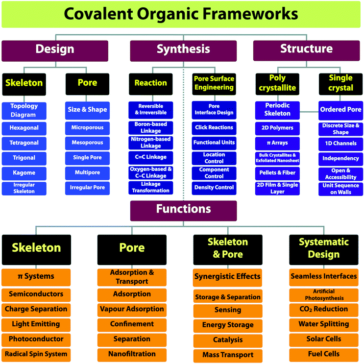
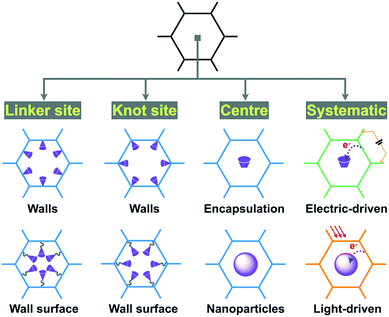
The progress over the past 15 years in chemistry has greatly increased our capabilities of structural design and extended further to the regime of materials functional design.10 In this review article, we offer a full materials and application picture of the field by disclosing a comprehensive yet clear guide for the design, synthesis, properties and applications of COFs (Scheme 1). We focus on scrutinising building blocks, reactive sites and functional groups as they not only enable the broad diversity of structures but also determine the multiple functionalities. Based on these detailed surveys, we unveil the strategies on how to design COFs, how to synthesise predesigned and tailor-made COFs and various interfaces and how to explore functionalities and develop applications. By elucidating the interplays of skeletons and pores with photons, excitons, phonons, polarons, electrons, holes, spins, ions and molecules, we show the current status of our understandings of structure–property correlations and unveil the guidance for designing properties and functions, with the aim of establishing a regime for developing unique functions that originate from and are inherent to COF structures. With the analyses of the current status of the field, we show the key primary issues in relation to the structure design and synthesis, challenges in developing functions and future research directions.
2. Building blocks
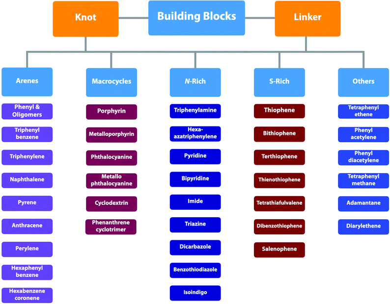
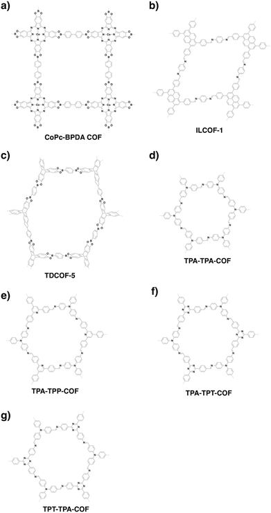
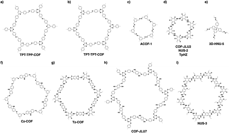
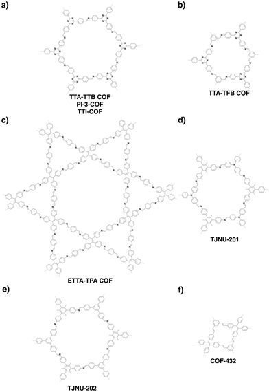
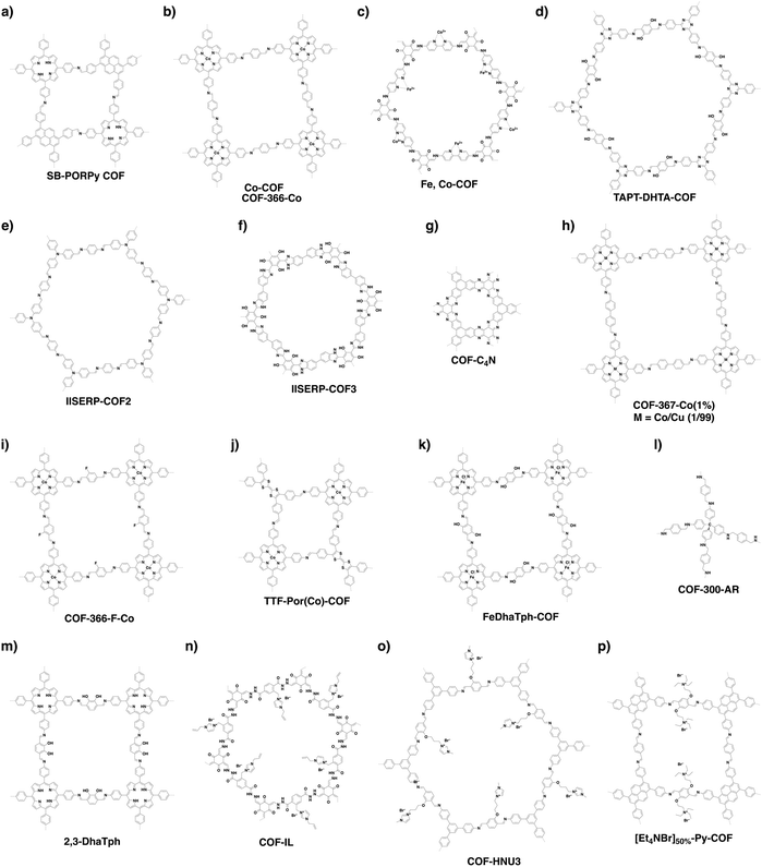
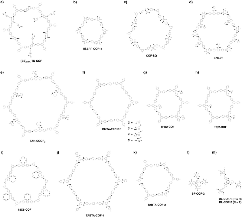
COFs can be topologically designed by deploying aromatic units with different geometries as monomers (Scheme 2). As such, it is important to recognise the symmetry elements, in particular, the rotational symmetry associated with the respective monomers. This can be done by identification of the rotational axes of the monomers. Conventionally, the rotational axis is designated as Cn, where rotation by (360°/n) restores the molecule to its original orientation. To ensure well-defined chain growth in a 2D or 3D manner, the building units are usually aromatic rings with rigid backbones so that bond connection and backbone propagation can be spatially guided. Building blocks including arenes, macrocycles, N-rich units, S-rich units and other π backbones have been developed. Fig. 1 and 2 show major monomers based on their geometries and reactive units. To ensure the topological growth across the polymer network, reactive sites are usually distributed in the aromatic systems to form a specific geometry. Except for self-condensation, designing COFs requires at least two monomers, in which one serves as a knot and the other functions as a linker; the knot units locate at the branch sites so that they are connected with linkers via covalent bonds to form polygonal backbones. Besides reactive sites, monomers can be integrated with functional groups for pore wall interface engineering. Therefore, building blocks offer a basis for not only designing COFs and but also determining properties and functions.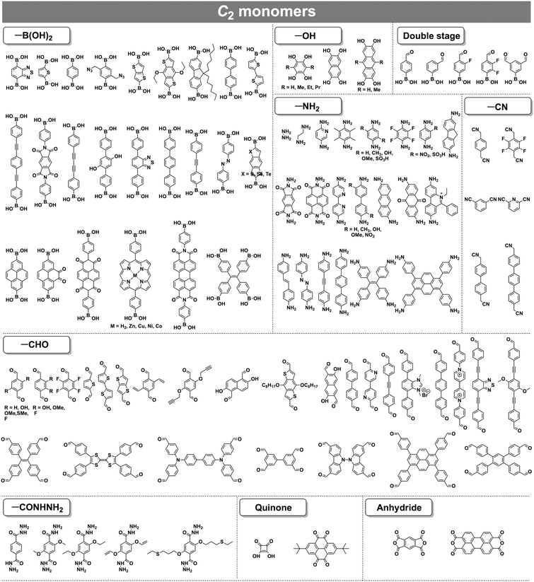 | ||
| Fig. 1 Typical building blocks with different geometries and reactive sites for the construction of COFs. | ||
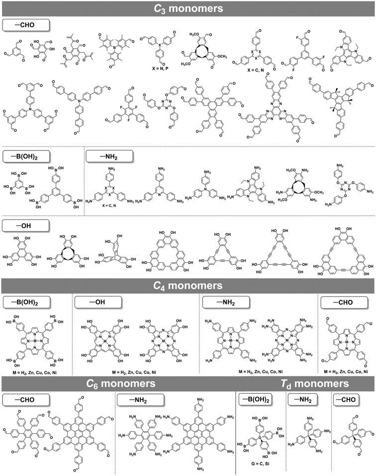 | ||
| Fig. 2 Typical building blocks with different geometries and reactive sites for the construction of COFs. | ||
2.1 Design principle and structural diversity
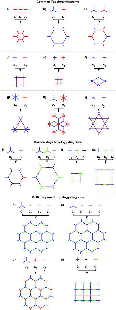
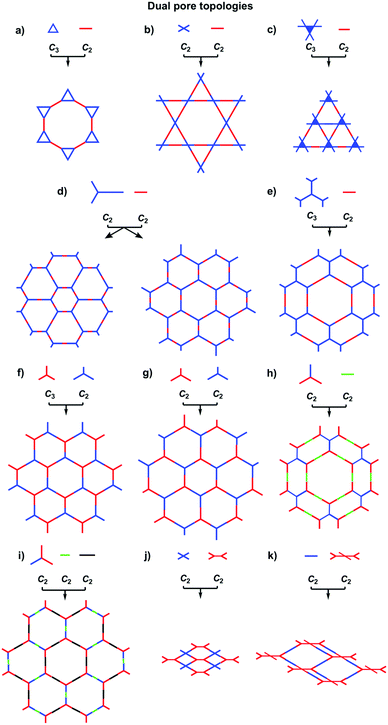
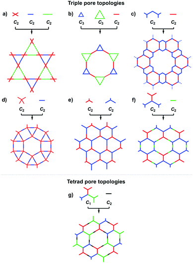
COFs can be designed by using topology diagrams, wherein knots and linkers with different geometries are condensed to form extended polygonal structures. 2D and 3D COFs require different topology diagrams. To date, various topology diagrams have been developed for the design of 2D and 3D COFs. Based on their geometry, monomers can be categorised into C1, C2, C3, C4, C6 and Td geometries, while the Td geometry is a must for designing 3D COFs (Fig. 1 and 2).10,112D COFs can be designed using monomers with C1, C2, C3, C4 and C6 geometries, in which the C2, C3, C4 and C6-symmetric monomers serve as knots. In the self-condensation case, the [C2 + C2 + C2] combination enables the design of hexagonal 2D COFs (Fig. 3a); this is mainly used for developing boroxine and triazine linked frameworks.12–14 In two-component [1+1] polycondensation systems with one knot and one linker, the [C3 + C2] and [C3 + C3] combinations yield hexagonal 2D COFs (Fig. 3b and c),15–38 while the [C4 + C2] and [C4 + C4] combinations generate tetragonal 2D COFs (Fig. 3d and e)39–44 and the [C2 + C2] and [C6 + C2] combinations form rhombic (Fig. 3f)45–47 and trigonal 2D COFs (Fig. 3g),26,48,49 respectively. In addition, the [C3 + C6] diagram produces a rhombic topology (Fig. 3h).50 The trigonal, tetragonal, rhombic and hexagonal topologies are the major forms of 2D COFs. Interestingly, besides the rhombic shape, the [C2 + C2] combination (Fig. 3i) can be used to design kagome-type COFs to create dual pore structures.51–57 Besides these common topologies, the combinations of monomers with certain symmetries generate multipore COFs (refer to Section 4.4 Multiple pores).
The exploration of a C1-symmetric unit bearing two different reactive sites enables the design of double-stage COFs in which various multicomponent combinations including [C3 + C1], [C3 + C3 + C1], [C4 + C4 + C1] and [C4 + C2 + C1] demonstrated the design of hexagonal, tetragonal and rhombic 2D COFs (Fig. 3j–m).58–61 A general strategy has been explored for designing COFs with multicomponent [1+2] and [1+3] systems to produce COFs with one knot and two or three linkers.62,63 Interestingly, this strategy is widely applicable to both hexagonal (Fig. 3n–p) and tetragonal (Fig. 3q) topologies. One significant feature is that multicomponent systems create a unique class of COFs in which the polymer backbones are tiled in an anisotropic way and the pores have a specific shape of an irregular polygon, thus opening a platform for the construction of complex frameworks while retaining their structural integrity. Another distinct character is that multicomponent systems greatly increase the diversity of COFs. Taking hexagonal 2D COFs as an example, for the combination of 1 knot and 10 linkers, 10 different COFs can be designed using the conventional [1+1] two-component strategy. In sharp contrast, 210 COFs with different structures can be created using the multicomponent strategy. A similar [C6 + C3 + C2] strategy has been explored for the design of 2D COFs with a tth topology.50
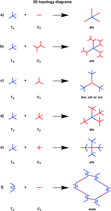
In order to design 3D COFs, a knot unit with Td or orthogonal symmetry is essential to grow polymer backbones in a 3D manner (refer to Section 2.8 3D knots). However, interpenetration of various degrees is present in 3D COFs (Fig. 4), including dia (Fig. 4a and d),64–66pts (Fig. 4b and e),67–69ctn (Fig. 4c),70bor (Fig. 4c),70–72srs (Fig. 4c)73 and helical structures (Fig. 4f).69,74,75
The ctn and bor networks are designed using the [Td + C3] combination, which yields 3D COFs free of interpenetration with high surface areas. The dia network is formed using the [Td + C2] and [Td + Td] diagrams that produce the largest family of 3D COFs owing to the broad diversity of C2-symmetric linkers. The dia network is interpenetrated to various degrees and forms 1D microporous channels with window sizes between 0.7 and 1.5 nm. The srs network is designed using the [Td + C3] combination, which is only observed for SiCOF-5 with a two-fold interpenetrated skeleton.73 The pts network can be designed using the [Td + C2] diagram in which the C2-symmetric monomer serves as a knot to have four reactive sites, forming two-fold interpenetrated 3D COFs with only two examples. Designing an orthogonal Cu(II) complex of phenanthroline as the knot to condense with a C2-symmetric linker yields 3D COF-505 with a helical structure.
3D COFs consist of interpenetrated networks, where the multiplicity of interpenetration affects both their structures and properties. Currently, the structures of building blocks cannot predict the multiplicity of folding in the resulting COFs and the structural parameters that control the folding remain unclear. In this context, it is still difficult to develop predesigned or tailor-made 3D COFs. Most 3D COFs have micropores but they usually show low porosity owing to the interpenetration. Controlling interpenetration to enhance porosity is an issue worthy of future investigation.76 Recently, a strategy by introducing side groups into the building blocks has been developed for tuning the interpenetration.69,77
The topology diagram offers the principle for designing 2D and 3D COFs and provides a basis for the COF field. The structural diversity of COFs is determined by the availability of topology diagrams and building blocks. A variety of building blocks with different reactive sites, such as boronic acids, amines, aldehydes, catechols, squaric acid, quinones, hydrazines, anhydrides, benzylnitriles, fluorobenzenes and silanols, have been developed for designing COFs to achieve different polygonal structures (Fig. 1 and 2).10,11 Compared to traditional 1D polymers, the diversity of COFs is greatly enhanced as the geometry factor greatly increases the diversity of monomers.
The topology diagram has been evolved from the initial hexagonal to tetragonal, rhombic, trigonal and kagome shapes. The building blocks have been developed from simple arenes to large π systems, electron donors and acceptors, coordination sites, catalytic units and spin systems. Likewise, the linkages have changed from non-conjugated to partially π conjugated and fully π conjugated. Moreover, the lattice has been developed from isotropic to anisotropic tiling. These changes greatly enhance the structural diversity of COFs and expand the scope of their properties, functions and applications.
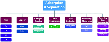
2.2 Adsorption units
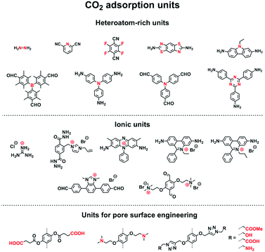
COFs offer well-defined nanospaces that can accommodate a diversity of gases, vapours, metal ions, charged species and organic compounds. Integrating specific units to constitute an interface for enhancing the interactions with guest molecules offers a general strategy for designing COFs for adsorption.70,78–80 The design of pore size, pore shape and pore wall interfaces is of critical importance; these parameters are key factors to be considered for designing COFs to adsorb guest molecules.Pore wall interfaces play a key role in controlling CO2 adsorption as they determine interactions with CO2 (Fig. 5). Pore surface engineering has shown its ability to enhance adsorption capacity by integrating functional groups into the pore walls of COFs to create tailor-made interfaces. A series of COFs with specific pore wall functional groups, such as carboxylic acid, amine and alcohol units, exhibit high efficiency in CO2 adsorption.88,89
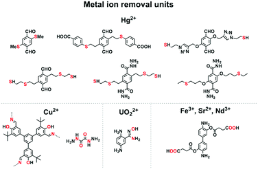
Mercury is a pollutant to the environment and harmful to health. It is well known that mercury can be trapped with sulphur-rich units via coordination. Hence, exploring building blocks with sulphur sites offers an efficient way to design COFs for the removal of mercury. A series of sulphur-containing COFs with different building blocks, such as methyl sulphide units22 and thioether groups,90 that show high capacities have been developed (Fig. 6). Pore surface engineering to integrate sulphur units via thiol–ene click reaction yields COFs with ultrahigh affinity for Hg(II) ions (Fig. 6).91,92 The sulphur-containing functional units in COFs coordinate with Hg(II) and improve the selectivity for Hg(II) ions.
Building units enriched with heteroatoms act as receptors for metal ions (Fig. 6). For example, designing COFs with 1,3,5-tris(3′-tert-butyl-4′-hydroxy-5′-formylphenyl)benzene units enables a high selectivity for Cu(II) ions via coordination by heteroatoms.93 The oxalyldihydrazide (ODH) unit with adjacent O and N atoms enables coordination with Hg(II) and Cu(II) ions.94 Integrating amidoxime units onto the pore walls leads to the removal of uranium ions via coordination.95–97
Carboxylic acid units are useful for removing metal ions. Integrating carboxylic acid units into skeletons via postmodification endows 3D COFs with high surface area, stability and crystallinity, and these COFs exhibit high removal selectivity and capacity for Nd(III), Sr(II) and Fe(III) ions.98
Another way is to control the pore size of COFs so that small molecules can be adsorbed, while large molecules are excluded. A series of COFs with different pore sizes have been synthesised, which separate different organic compounds.100,101 3D COFs with ion exchange capability show an enhanced adsorption capacity.87
2.3 Semiconducting units
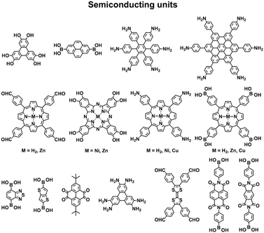
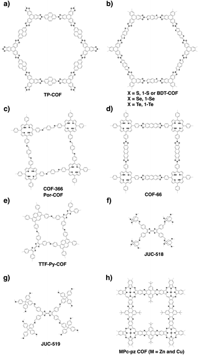
COFs are constructed with π units and consist of topologically aligned columnar π arrays, offering an irreplaceable platform for designing semiconductors (Fig. 7). We reported the first example of semiconducting TP-COF in 2008. The well-defined π columns provide pathways for carrier transport and increase charge carrier mobility. These structural features are inaccessible to traditional semiconductors and have a great impact on the conduction of electrons and holes.12,15Triphenylene and pyrene with planar structures are suitable building blocks for the construction of semiconducting COFs.15 Other π units such as thiophene16,104 and anthracene105 have been developed as building units for the synthesis of semiconducting COFs. Hexaphenylbenzene and hexabenzocoronene are large π systems that lead to the generation of COFs with high mobility and photoconductivity.48 The polycondensation of triphenylene-2,3,6,7,10,11-hexamine (TPHA) and 2,7-di-tert-butylpyrene-4,5,9,10-tetraone (PT) yields fully π-conjugated CS-COF that exhibits exceptional performance in terms of carrier mobility and photoconductivity.106 Tetrathiafulvalene (TTF) is an electron donor and serves as a π unit for the construction of various hole-transporting COFs (Fig. 7).107–109
Porphyrins and metalloporphyrins are a typical class of macrocycles with 18 π electrons and serve as building blocks for designing various semiconducting COFs (Fig. 7). Integrating different metal species such as Ni(II), Cu(II), Zn(II), and Co(II) to synthesise metalloporphyrin COFs can tune the electron density on the porphyrin and carrier mobility.40,42,105,110–112 For example, integration of Cu(II) reduces the electron density of the porphyrin greatly and changes the original hole-transporting free-base porphyrin COF into an electron-transporting COF.
Phthalocyanines and metallophthalocyanines are another class of π macrocycles that have been developed as building blocks for designing semiconducting COFs (Fig. 7).39,113,114 As metalloporphyrins and metallophthalocyanines have strong absorption bands in the visible and near infrared regions and exhibit different catalytic activities, integrating these units into COFs greatly expands the scope of their properties to optoelectronics and catalysis.
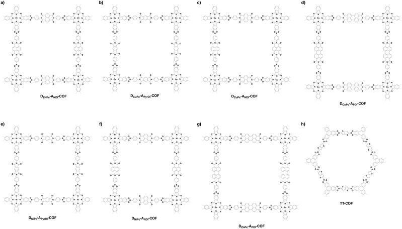
By aligning electron donors and acceptors into ordered structures, ideal donor–acceptor structures for semiconductors and optoelectronics can be designed. We have developed a strategy for designing donor–acceptor COFs by one-pot polycondensation of electron donor and acceptor units.115 Triphenylene and metallophthalocyanine units have been developed as electron donors, while benzothiadiazole and diimide units have been explored as electron acceptors. For example, using triphenylene as an electron donor unit and benzothiadiazole as an acceptor unit to construct donor–acceptor (D–A) COFs demonstrates that the donor and acceptor columns enable the transport of holes and electrons, respectively, leading to ambipolar conduction.115 Polycondensation of Cu(II), Ni(II) and Zn(II) phthalocyanine donors with pyromellitic, naphthalene and pyrene diimide acceptors yields a series of donor–acceptor COFs to create segregated bicontinuous donor and acceptor π-columnar arrays. These COFs enable efficient photoinduced electron transfer and charge separation and collection, offering a new mechanism for charge separation and energy conversion.116,117
2.4 Redox active units
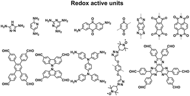
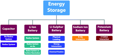
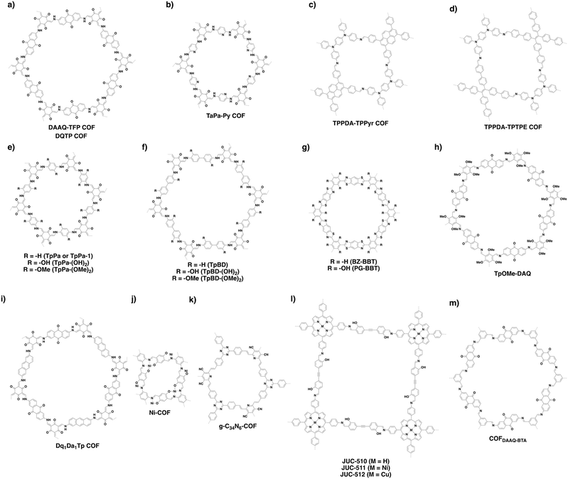
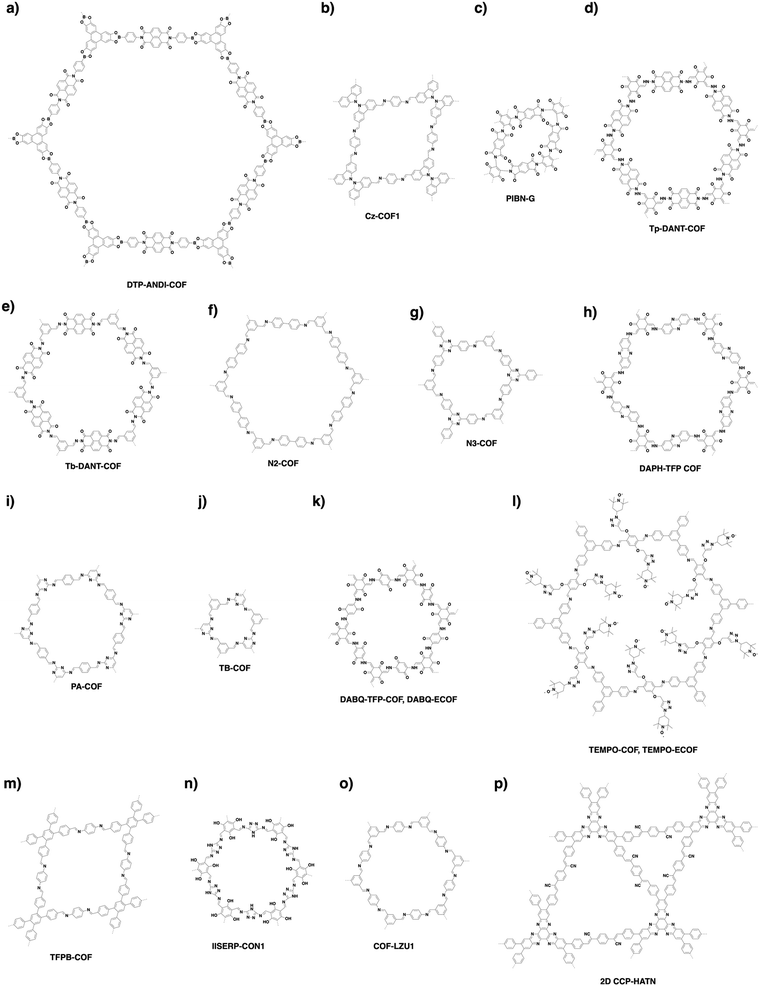
Redox-active building blocks are capable of oxidation and reduction so that electron injection and extraction become possible (Fig. 8). This process, coupled with electrodes, ions and electrolytes, enables a mechanism for energy storage. Integrating redox-active units into 2D COFs to form ordered π arrays and open nanochannels offers a platform for designing energy storage materials.118Redox-active units usually contain heteroatoms such as nitrogen and oxygen. A typical nitrogen-containing redox-active unit, i.e. bicarbazole, has been developed for synthesising COFs for energy storage.119 The pyridine unit is capable of reversible redox reaction and is a candidate for energy storage.120
A quinone is another unit that enables reversible oxidation and reduction and serves as a well-established building block to construct COFs for energy storage.121,122 The hydroxyl groups protect hydroquinone moieties from decomposition to increase chemical stability and achieve high capacity.123,124
Organic radical species are active for redox reactions. Another promising strategy for designing COFs for energy storage is to integrate radical units into the pore walls by pore surface engineering while retaining radical redox activities. Pore surface engineering of NiP-COF with 2,2,6,6-tetramethyl-1-piperidinyloxy (TEMPO) radicals on the pore walls via click reaction enables energy storage in [TEMPO]X%-NiP-COF.125
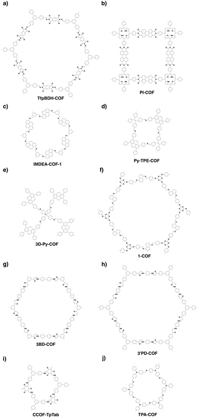
Exfoliating COFs to form few-layer sheets has been proved to be an effective strategy for enhancing their capacity, as a large number of redox active sites become accessible to the external environment. For example, PI-COFs with redox-active pyromellitic diimide units have been exfoliated into nanosheets, to form PI-ECOFs, which upon mixing with rGO yield a PI-ECOF/rGO composite. The resulting composite exhibits enhanced cycling stability and electrochemical performance, which originate from the enhanced accessibility to the redox-active sites.126 A series of COFs with redox-active building blocks, such as quinone,122,127 triazole128 and π-conjugated units,129 have been explored to prepare 2D COFs and their exfoliated nanosheets for energy storage.
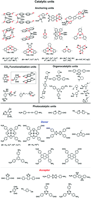
2.5 Catalytic units
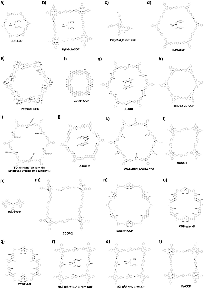
COFs enable the design of skeletons and pores for exploring heterogeneous catalytic systems. Catalytically active units can be condensed or post-synthetically integrated into the skeletons, leading to the construction of catalytic COFs. Due to the combination of their porosity and well-defined skeleton structure, these COFs trigger synergistic effects in catalysis that cannot be achieved with individual components. In this context, COFs have attracted great attention as a platform for designing catalysts. The diversity of building blocks enables the development of various catalytic systems. In this section, we look at and discuss catalytically active building blocks with the aim of elucidating the diversity and scope of catalytic COFs (Fig. 9).Metal complexes are one of the major classes of catalysts. Two different strategies for integrating metal complexes into the skeletons of COFs have been developed (Fig. 9). One is to coordinate metal ions to COFs that have coordination sites and the other is to use metal complexes directly as building units to design COFs (Fig. 9). For example, palladium ions can coordinate to nitrogen atoms of imine linkages between layers of COFs to form Pd@COF, which serves as a catalyst for the Suzuki coupling reaction.130–132 Besides, imine nitrogen serves as a monodentate ligand133 as well as an intra-layer bidentate ligand, allowing the development of various catalytic COFs.134 These post-synthetic approaches have been developed to prepare catalytic COFs with different metal ions, including Cu(II),135,136 Mn(II),137 V(IV)138,139 and Ti(IV).140 Metallosalens are versatile units for the design of catalytic COFs, as metallosalen complexes serve as catalysts to promote various reactions.141–144 The bipyridine unit binds a diversity of metal ions and nanoparticles and serves as an important unit for designing catalytic COFs.145–147 Due to the combination of stability and crystallinity, β-ketoenamine COFs are attractive as support materials for heterogeneous catalysis. Most importantly, they accommodate metal nanoparticles as the β-ketoenamine units coordinate with Pd(0), Pt(0) and Ag(0) metal nanoparticles.148–152
Lewis acids are capable of catalysing various reactions. These units have been developed for designing COFs that promote cycloaddition of CO2 with epoxides to form cyclic carbonates, as the Lewis acid unit serves as a hydrogen bond donor to epoxides to achieve this transformation (Fig. 9, H atoms in red). These Lewis acidic units include catechol units153 which are able to form intralayer oxyanion holes as well as hydroxyl units which form interlayer oxyanion holes.154 Besides hydrogen-bond donors, imidazolium units have been explored as building blocks for constructing COFs to activate epoxides by donating hydrogen on the middle carbon atom.155,156
Pyrrolidine derivatives play an indispensable role in the development of organocatalysts for a wide range of asymmetric organic transformations. Typically, they activate the participating carbonyl species via the formation of iminium or enamine intermediates, simultaneously inducing asymmetry for subsequent transformations. Building blocks with pyrrolidine groups (Fig. 9) have been developed by either post-synthetic modification157,158 or direct condensation159–162 to construct chiral COFs, which promote a range of asymmetric reactions such as Michael and aldol reactions.
Owing to their π units, COFs have been explored as photocatalysts to promote light-driven transformations (Fig. 9). Porphyrin derivatives have been well established as photosensitisers to transform triplet oxygen to singlet oxygen that is highly active for oxidation of organic compounds or cancer therapy. Integration of porphyrin units into COFs enables the design of porphyrin and metalloporphyrin COFs, which show enhanced activity in producing singlet oxygen and promoting in situ organo-transformation of sulphides into sulphoxides.163–167 Triazine units168–170 are unique in that they are planar and conjugated and form hydrogen bonds with sacrificial donors and stabilise negative charges. These features have been developed for designing triazine COFs that accelerate reactions.171,172 β-Ketoenamine knots in conjunction with conjugated and planar linkers have been used to design stable COFs for photocatalysis.173–175 For certain photocatalytic reactions, the co-existence of transition metal co-catalysts is necessary to drive the reaction. Building blocks such as bipyridine units that serve as ligands have been used for designing photocatalytic COFs.170,176,177 Photocatalysts require a suitable band gap and orbital levels for a specific reaction. Hence, the donor–acceptor strategy (Fig. 9) has been explored for tuning the band gap and energy levels of COFs.178–182 Fully π conjugated sp2c-COFs with electron-accepting units on the lattice periphery function as a new class of photocatalysts.183
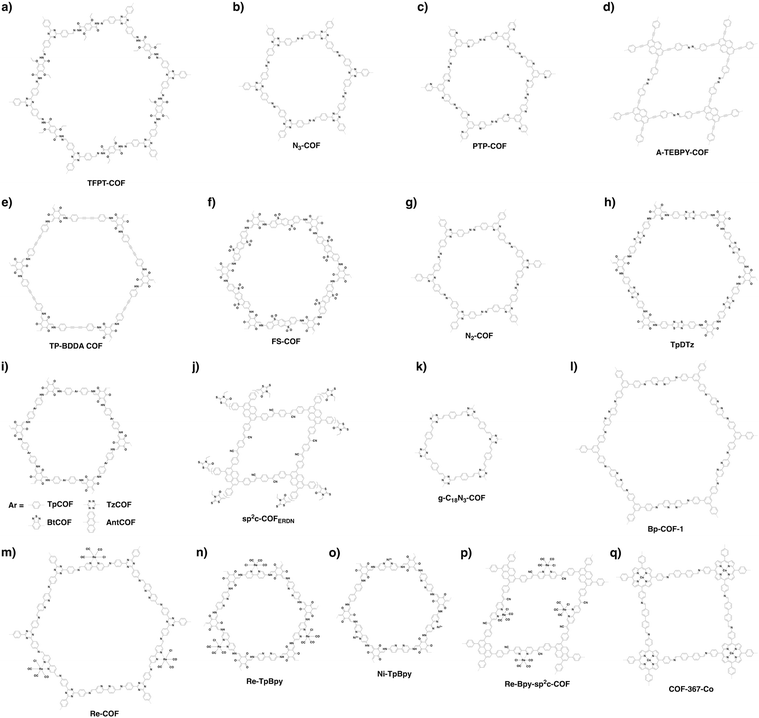
COFs with high porosity and crystallinity have been explored as electrocatalysts to accelerate the oxygen reduction reaction, oxygen evolution reaction, hydrogen evolution reaction and CO2 reduction. Pyrolysis has been developed to convert COFs into porous carbons to enhance conductivity and electrocatalytic activities. Pyrolysis of nitrogen rich COFs forms N-doped sites that are active for the oxygen reduction reaction and oxygen evolution reaction.184–186 Imine-linked nitrogen rich units such as porphyrin, metalloporphyrin, triazine and 1,3,5-tris(4-aminophenyl)benzene backbones have been developed for constructing COF-based electrocatalysts.187–190 Coordination sites such as bipyridine units that are capable of binding metal ions such as Co(II), Fe(II) and Fe(III) have been used for integrating metal species into the resulting porous carbons.191,192 The oxygen evolution reaction requires the presence of transition metals as the catalysts. Hence, building blocks with heteroatoms that are capable of ligating metal ions or nanoparticles have been explored for designing oxygen evolution reaction catalysts. These units include triphenylamine,193 benzimidazole194 and bipyridine.195,196 Metalloporphyrin units serve as an electrocatalyst for reducing CO2 to CO; metalloporphyrin COFs exhibit greatly improved electrocatalytic activity.197–199
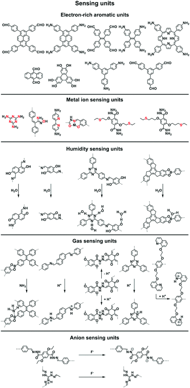
2.6 Sensing units
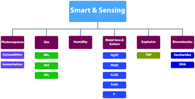
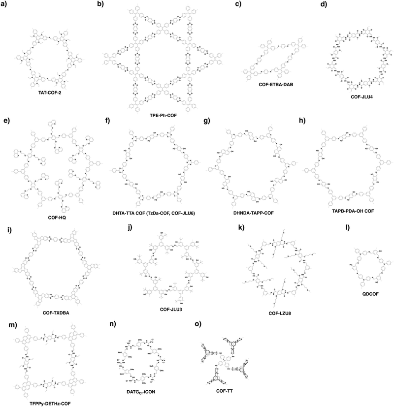
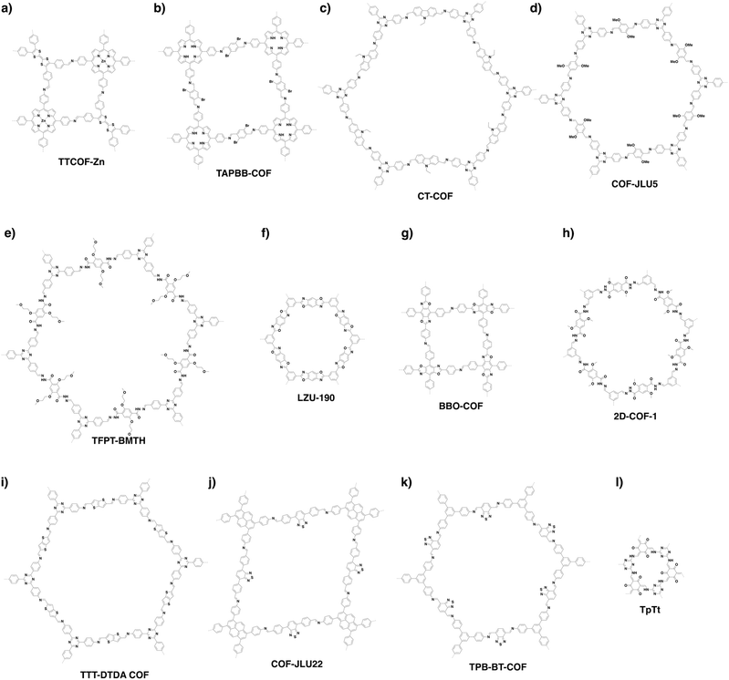
Sensing is based on the luminescence properties of COFs. Owing to the diversity of building blocks, COFs have been explored for sensing various targets including explosives, metal ions, humidity, gases, protons and anions.200 We reported the first example of luminescent COFs (TP-COF) in 2008. TP-COF is a highly luminescent COF with triphenylene and pyrene as luminescent units.15 Other arene units such as diphenylbutadiyne have been developed to synthesise HHTP-DPB COF that exhibits luminescence and is expected to be a sensor.201Fig. 10 summarises the electron-rich aromatic units for constructing imine-linked luminescent COFs.In order to detect explosives such as 2,4,6-trinitrophenol (TNP) derivatives, the azine linkage in conjunction with the pyrene unit is effective, as the azine unit interacts with TNP via hydrogen bonding, while the pyrene unit serves as a reporter for the fluorescence change, leading to high sensitivity and selectivity.202 Nitrogen-containing units such as hydrazine, 1,3,6,8-tetrakis(4-aminophenyl)-pyrene, 1,3,5-tris(4-aminophenyl)benzene and tetrakis(4-aminophenyl)ethylene or electron-rich aromatic units including 1,3,6,8-tetrakis(4-formylphenyl)pyrene, 1,1,2,2-tetrakis(4-formylphenyl)ethane, 1,3,5-tris(4-formylphenyl)benzene and 9,10-anthracenedialdehyde serve as building blocks for the synthesis of imine-linked COFs,25,203–207 which function as fluorescence detectors of TNP type explosives.
Building units containing N or S atoms such as melamine, 2,5-bis(3-(ethylthio)propoxy)terephthalohydrazide, 2,5-bis(2-(ethylthio)ethoxy)terephthalohydrazide and polyimide bonds can bind metal ions; the resulting luminescent COFs detect various metal ions such as Cu(II),93,208 Hg(II),90 Au(I),209 UO2(II),96,210 Tb(III)211 and Fe(III)212,213via fluorescence quenching.
COFs have been developed for sensing humidity (Fig. 10). One strategy is to explore the tautomerisation between enol and keto units that is driven by water; building blocks containing enol groups such as 2,6-dihydroxynaphthalene-1,5-dicarbaldehyde214 and 2,4,6-triformylphloroglucinol33 are effective. The 1,3,5-tris(4-aminophenyl)triazine unit with both the triazine docking site and hydroxyl group is responsive to humidity when integrated into TzDa-COF owing to intramolecular charge transfer and excited state intramolecular proton transfer.215 The truxene unit is luminescent and the resulting TXDBA-COF responds to humidity via Lewis-acid–base interactions.216
Tetraphenylethylene (TPE) is a unit that exhibits aggregation-induced emission and serves as a knot for the construction of light-emitting boronate ester linked TPE-Ph COF. The TPE-Ph COF detects ammonia via Lewis acid–base interaction between the 2pz orbital of boron in boronate ester linkage and the lone pair of nitrogen in ammonia (Fig. 10).55 The imine-linked TPE COF, i.e. COF-ETBA-DAB, is highly sensitive to gaseous HCl via the protonation of N atoms.217 Protonation of the imine bonds in perylene COFs causes significant protonation-induced colour shift; these COFs have been developed for sensing acid vapour.218 Similar protonation behaviours are observed for hydrazone-linked COF-JLU4219 and quinoline-linked COF-HQ, which are responsive to the pH value of solution.220
The hydrazone linkage is unique as it can be deprotonated by F− anions. Hydrazone-linked TFPPy-DETHz-COF (Fig. 10) detects F− anions via a switch-on mechanism, as the deprotonation of the hydrazone unit increases the luminescence of the framework.47
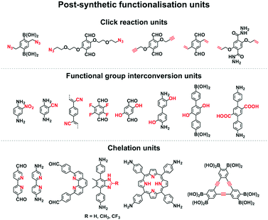
2.7 Post-synthetic functionalisation units
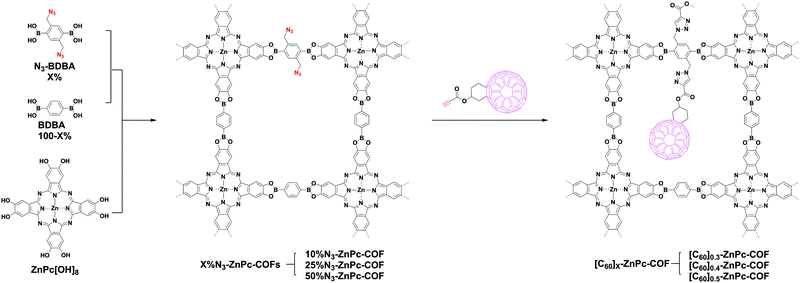
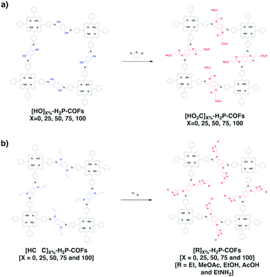
Functionalisation of COFs after synthesis has been explored by two methods; one is pore surface engineering and the other is linkage transformation (refer to Section 4.5 Pore interface design). Fig. 11 summarises the building blocks used for functionalisation of COFs.We developed a pore surface engineering strategy for functionalisation of pore walls to create tailor-made pore environments and interfaces. The building unit that enables such functionalisation is the azide group that reacts with alkynes via click reaction (Fig. 11) to integrate various functional groups onto pore walls, which have been developed for gas storage,221 photoinduced electron transfer and charge separation.222 Conversely, the alkyne units that react with various azides have been developed to construct COFs with different functions.89,157,223 Similarly, thiol–ene reactions between C![[double bond, length as m-dash]](https://www.rsc.org/images/entities/char_e001.gif) C bonds and thiols have been used for functionalisation of COFs, clicking with thiols.91,224,225 The C
C bonds and thiols have been used for functionalisation of COFs, clicking with thiols.91,224,225 The C![[double bond, length as m-dash]](https://www.rsc.org/images/entities/char_e001.gif) C bonds in COFs react with sulphur (S8) to offer an effective functionalisation method.226
C bonds in COFs react with sulphur (S8) to offer an effective functionalisation method.226
Functional group interconversion allows access to other functional groups (Fig. 11). For example, nucleophilic substitution enables the attachment of S8 to COF-F with aryl fluoride units. The building blocks containing the ester group have been developed for functionalisation of TS-COF and CTF-CSUs with amino groups to form amide units.227,228 Building blocks with the carboxyl group have been developed to construct COF-616, which enables post-synthetic amidation, esterification and thioesterification reactions.97 The post-synthetic functionalisation of phenol moieties has been developed to synthesise various functional COFs. The building blocks with phenol can react with a series of functional groups, such as anhydrides,88 carboxylic acids,98 alkyl bromides,85 betaine groups,229 epoxy rings230 and isothiocyanates.231 The reduction of azides to amines is an effective approach to amino-functionalised [NH2]-COFs. Building blocks with the azide moiety have been developed to construct [N3]-COFs that can be further reduced to the corresponding [NH2]-COFs by PPh3 in CH3OH.99 TpPa-NO2 COF with nitro units is successfully transformed into amino-functionalised TpPa-NH2 COF in the continuous microdroplet flow reaction of 1,3,5-triformylphloroglucinol (Tp) with 2,5-dinitro-1,4-phenylenediamine by simultaneous reduction with SnCl2.232 The 2,5-diaminobenzonitrile unit with the cyano group yields COF-TpDb, which can be amidoximated via the reaction of hydroxylamine with cyano groups to afford amidoxime-functionalised COF-TpDb-AO.95 Similar strategies have been explored for COF-PDAN-AO. COF-PDAN with cyano units is transformed into amidoxime-functionalised COF-PDAN-AO via reaction with hydroxylamine in ethanol.210
Building blocks that are capable of chelating with metal ions can functionalise COFs through post-synthetic metalation (Fig. 11). Bipyridine moieties can coordinate various metal ions, such as Pd(II),145 Mn(II),145 Re(II),170 Rh(II),146 Co(II),195 Fe(II)233 and Cu(II),234 are used in the construction of heterogeneous catalysts. Monomers containing imidazole units are useful for designing H-ImCOF, CH3-ImCOF and CF3-ImCOF that react with metal ions to form metal imidazolates.235 As porphyrin and phenanthroline units coordinate with various metal ions, Fe-DhaTph-COF, COF-Re and COF-505 with porphyrin and phenanthroline units are easily metalated to develop catalysts.236–238 A monomer containing the dehydrobenzoannulene group has been developed to synthesise a 3D COF (DBA-3D-COF) via coordination with metal ions.71 Linkages such as imines130,131,239,240 and β-ketoenamines241–243 serve as ligands for metal ions, in which the hydroxyl group strengthens the coordination and the linkage.135,141,244,245
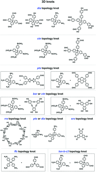
2.8 3D knots
3D COFs have been designed by using units with Td or orthogonal geometry as knots. The combination of knots with different linkers yields 3D COFs with various networks, including dia,64–66pts,67,68ctn,70bor,70,71srs,73 and helical74 structures (Fig. 4). A diversity of units with different geometries (Fig. 12) have been developed for the design of 3D COFs.The Td-symmetric tetraphenylmethane unit upon condensation with C2-symmetric knots yields dia networks, such as 3D-HNU5,246 JUC-509,144 COF 2-Zn,247 LUZ-79,248 COF-300,249 COF-300-V,250 COF-303,248 MCOF-1,251 JUC-550,77 and 3D-ionic-COFs.87 3D COFs JUC-51968 and 3D-Py-COF252 with a pts topology are constructed by condensing the Td-symmetric tetraphenylmethane knot and C2-symmetric four-branched unit. The Td-symmetric tetraphenylmethane knot in combination with C3-symmetric units constitutes bor networks (COF-10870,253 and DBA-3D-COF71) or a ctn framework (COF-10570,253). The combination of a tetraphenylmethane knot and C4-symmetric units yields 3D-Por-COF and 3D-TPE-COF with a pts topology.66,165 The ctn topology of COF-10270,254,255 is realised via the condensation of two tetraphenylmethane units. The tetraphenylsilicon knot forms 3D COF-103256,257 and COF 1-Zn.247 The adamantane unit yields 3D COFs with pts (COF-DL229103) or dia (JUC-51868) nets. The phenanthroline unit upon coordination with metal ions serves as a knot to construct helix 3D COF-505.74
Recently, various building units have been explored to construct 3D COFs with topologies such as rra, srs, ffc and lon. Cyclodextrin has been developed for the construction of 3D-CD-COF with a rra topology through spiroborate linkages.258 A tritopic catecholate unit has been explored to react with hexacoordinate [SiO6]2− to form 3D SiCOF-5 with an srs topology.73 Tetrakis(4-aminophenyl)ethylene, 1,3,5-tri(4-formylphenyl)benzene and tris(4-formylphenyl)amine have been developed to produce 3D-ETTA-TFPA and 3D-ETTA-TFPB with an ffc net.259 The combination of two Td-symmetric monomers, i.e. tetrakis(4-aminophenyl)methane and tetrakis(4-formylphenyl)silane yields chiral 3D LZU-111 with a three-fold interpenetration lonsdaleite (lon-b-c3) network.248 Terephthalaldehyde and 2,4,6-trimethyl-1,3,5-triazine have been developed to construct vinylene-linked 2D P2PV, which can be transformed into cyclobutane-linked 3D P3PcB via [2+2] photocycloaddition reaction.260
3. Skeletons
3.1 Lattice and linkage diversities
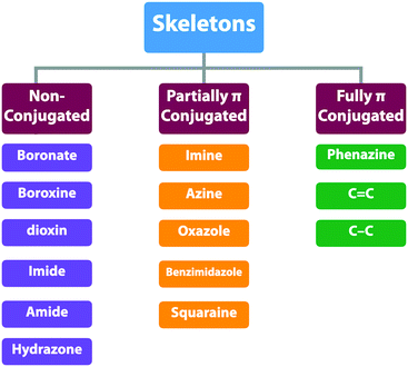
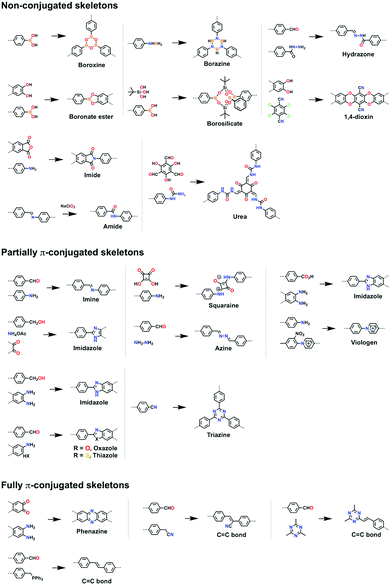
COFs enable the topology-guided growth of polymer backbones into well-defined polygonal structures. Both 2D and 3D COFs can be designed to have a diversity of topologies or nets, which offer a chemical basis for the diversity of both structures and functions. The organic units are covalently connected by different linkages and determine the overall intralayer electronic interactions between knots and linkers. From a π electronic perspective, the linkages can be categorised into three classes: (1) non-conjugated linkages; (2) partially conjugated linkages and (3) fully conjugated linkages (Scheme 3 and Fig. 13). The difference of these linkages exerts profound effects on skeletons especially their π structure, frontier orbital energy levels, and band gap and thus properties and functions. As linkages are formed via the reaction between knots and linkers, the monomer structure and post-synthetic transformation determine the nature of the linkages.3.2 Non-conjugated skeletons
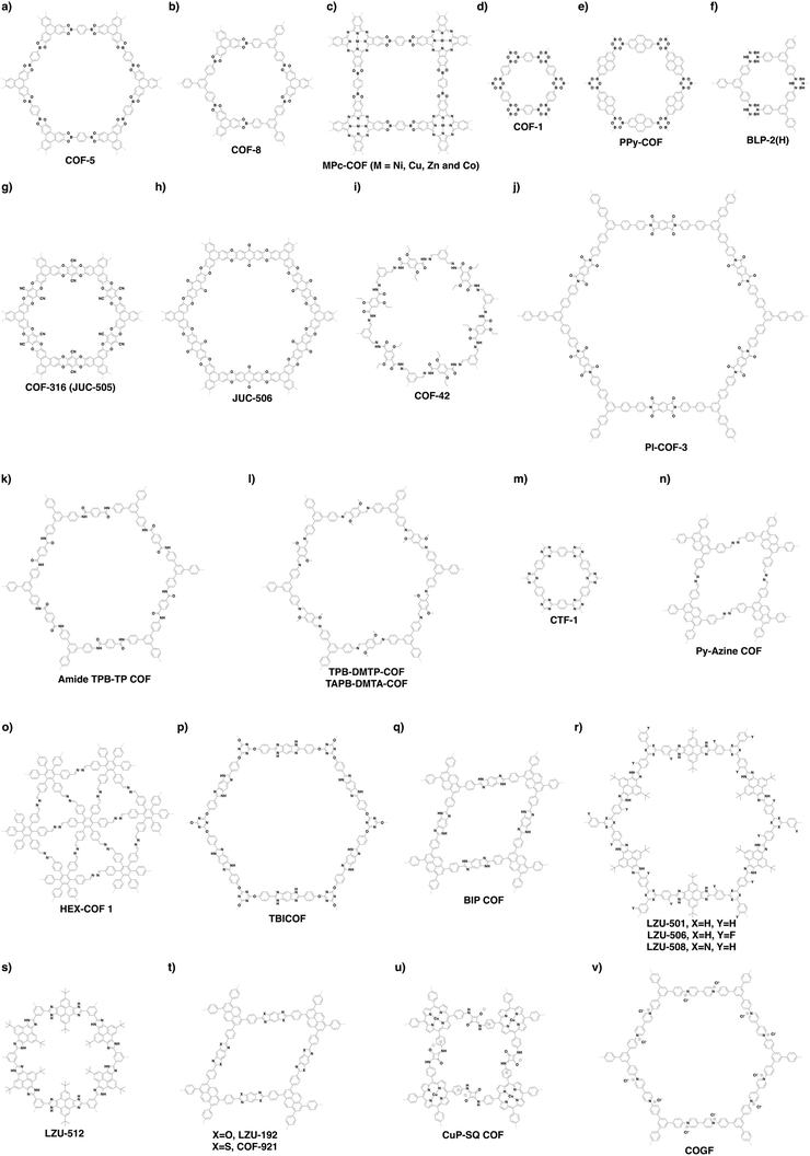
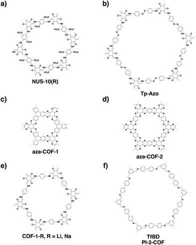
Non-conjugated linkages have been explored using various bonds, including boronate ester, boroxine, borosilicate, borazine, dioxin, hydrazone, imide, amide and urea linkages (Fig. 13). The condensation of boronic acids and catechol derivatives yields boronate ester-linked COFs (Fig. 14a–c). Various π systems including benzene, biphenyl, anthracene, triphenylbenzene, triphenylene, thiophene, porphyrin, phthalocyanine and tetraphenylethene derivatives have been used to prepare 2D boronate ester-linked COFs.55,201,261–265 Interestingly, boronate ester-linked 3D COFs have been synthesised from Td-symmetric monomers. 3D COF-102 and COF-103256 are constructed by using tetra(4-dihydroxyborylphenyl)methane and tetra(4-dihydroxyborylphenyl)silane as monomers, respectively. The synthesis of borosilicate-linked COF-202266 has been carried out by condensing tert-butylsilane triol and tetra(4-dihydroxyboryl phenyl)methane. Boroxine-linked COFs have been synthesised by the self-condensation of boronic acids. The self-condensation of 1,4-benzenediboronic acid yields COF-1 (Fig. 14d)267 with a pore diameter of 1.5 nm, while PPy-COF (Fig. 14e) with a pore size of 2.0 nm268 is formed by the self-condensation of pyrene-2,7-diboronic acid. BLP-2(H) COF (Fig. 14f)269 with borazine linkages has been synthesised by the thermal decomposition of 1,3,5-(p-aminophenyl)benzene-borane.The condensation of ortho-difluorobenzene or -pyridine and catechol yields dioxin-linked COFs in the presence of a base. COF-316 (the same structure as JUC-505) (Fig. 14g)270,271 has been prepared by condensing HHTP with tetrafluorophthalonitrile. Condensing 2,3,5,6-tetrafluoro-4-pyridinecarbonitrile with HHTP yields COF-318,271 while JUC-506 (Fig. 14h)270 is synthesised by condensing HTTP with 2,3,6,7-tetrafluoroanthraquinone.
Hydrazone linkages are constructed via the condensation of hydrazides and aldehydes. COF-42 (Fig. 14i)272 has been synthesised by condensing 2,5-diethoxyterephthalohydrazide (DETH) with 1,3,5-triformylbenzene (TFB). Replacing TFB with 1,3,5-tris(4-formylphenyl)benzene (TFPB) yields COF-43.272 Condensing nitrogen-rich 1,3,5-tris-(4-formyl-phenyl)triazine (TFPT) with DETH forms TFPT-COF.168 Hydrazone-linked COF-JLU4219 is prepared by condensing 1,3,5-triformylphloroglucinol with 2,5-dimethoxyterephthalohydrazide, while LZU-21273 is synthesised by condensing 6,6′-bis(dimethoxymethyl)-3,3′-bipyridine with 1,3,5-tris(4-aminophenyl)benzene.
Imide linkages are formed by the reaction of amines with anhydrides at a high temperature such as 200 °C. Condensing pyromellitic dianhydride with tris(4-aminophenyl)amine, 1,3,5-tris(4-aminophenyl)benzene and 1,3,5-tris[4-amino(1,1-biphenyl-4-yl)]benzene yields PI-COF-1, PI-COF-2 and PI-COF-3 (Fig. 14j), respectively.17 Notably, PI-COF-3 has a hexagonal pore size of 5.3 nm. Condensing 1,3,5,7-tetraaminoadamantane or tetra(4-aminophenyl)methane with pyromellitic dianhydride yields 3D PI-COF-4 or PI-COF-5.65 Recently, substoichiometrical condensation of C3-symmetric 1,3,5,7-tetraaminoadamantane and C2-symmetric 1,3,6,8-tetra(4-formylphenyl)pyrene (TFPPy) yields COF-76 1D ribbons bearing free amines, which react with pyromellitic dianhydride to generate imide-linked COF-78.63
Linkage transformation offers a way to connections which are difficult to prepare directly. Amide-linked COF 1′ (Fig. 14k) and COF 2′ have been synthesised by oxidizing imine-linked TPB-TP-COF and 4PE-1P-COF with sodium chlorite.274
Urea-linked COF-117 and COF-118 have been synthesised by condensing 1,3,5-triformylphloroglucinol with 1,4-phenylenediurea and 1,1′-(3,3′-dimethyl-[1,1′-biphenyl]-4,4′-diyl)diurea, respectively.275
3.3 Partially π-conjugated skeletons
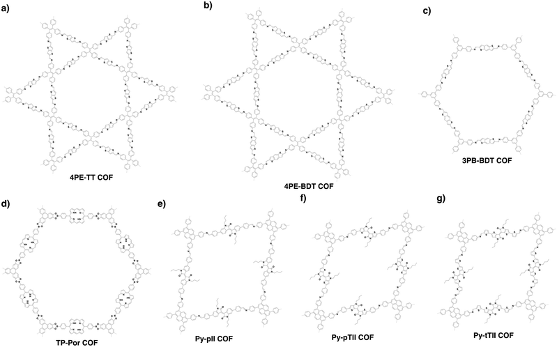
Partially π-conjugated linkages usually contain nitrogen atoms and have been broadly explored using imine, triazine, azine, imidazole, oxazole, thiazole, squaraine and viologen bonds (Fig. 13). The condensation of aromatic amines and aldehydes yields imine-linked COFs. For example, we have developed TPB-DMTP-COF (Fig. 14l) by the reaction of 1,3,5-tris(4-aminophenyl)benzene with 2,5-dimethoxyterephthalaldehyde (DMTP).158 An imine linkage presents much higher stability than boronate ester and boroxine linkages, constituting a family of the most extensively synthesised COFs. The π backbones of amines and aldehydes are quite broad in diversity and include benzene,130,244,276,277 biphenyl,278,279 bipyridine,146,244 thiophene,278,280,281 triphenylbenzene,282,283 triphenyltriazine,284 tetraphenylethene,54,56,278 tetraphenylpyrene,110,244,285 porphyrin,28,164,286,287 tetrathiafulvalene,288,289 hexaazatriphenylene,290 dehydrobenzoannulene,31 trioxaazatriangulene,291 hexaphenylbenzene and hexabenzocoronene derivatives.48 Meanwhile, 3D imine-linked 3D-BMTA-COF utilises 3,3′,5,5′-tetra(p-aminophenyl)-bimesitylene (BMTA)69 as knot. Imine-linked helix 3D COF-505238 has been synthesised by the reaction of Cu(I)-bis[4,4′-(1,10-phenanthroline-2,9-diyl)dibenzaldehyde]tetrafluoroborate with benzidine. COF-505 presents interlocked organometallic helical threads to form an interweaving structure.COFs have been synthesised by using Td-symmetric tetra-(4-aminophenyl)methane,252,292 tetrakis(3-formyl-4-hydroxyphenyl)methane (TFHPM),144 1,3,5,7-tetraaminoadamantane,293 and 2,2′,7,7′-tetramethoxy-9,9′-spirobi[fluorene]-3,3′,6,6′-tetracarbaldehyde (TMSFTA),77 and covalent triazine frameworks (CTFs) with triazine linkages have been synthesised by ionothermal condensation of benzonitrile in molten ZnCl2 at 400 °C.294 When trifluoromethanesulphonic acid is used as a catalyst, CTFs can be prepared at a lower temperature, leading to a higher purity of CTFs.295 Very recently, highly crystalline and porous pCTF-1 (Fig. 14m) has been synthesised by the condensation of benzamide as well as benzonitrile with P2O5 catalyst.296
Azine linkages have been developed by condensing aldehydes with hydrazine. Rhombic, hexagonal and trigonal azine-linked COFs have been synthesised by using pyrene (Fig. 14n),202 substituted benzenes,18,297,298 triphenyltriazine,169 dehydrobenzoannulene and hexaphenylbenzene as knots (Fig. 14o).81
Imidazole linkages have been prepared via the condensation of aldehydes with diamino units. TBICOF (Fig. 14p) has been synthesised by condensing 1,2,4,5-tetraaminobenzene (TAB) with tri(4-formylphenoxy)cyanurate (TFPC) in the presence of imidazole.299 Another way to the formation of an imidazole linkage is the condensation of carboxylic acid with the diamino unit. For example, condensing 4,4′,4′′,4′′′-(pyrene-1,3,6,8-tetrayl)tetrabenzoic acid with TAB yields BIP COF (Fig. 14q) with polyphosphoric acid catalyst.300 Very recently, a multicomponent strategy has been developed to construct a series of imidazole-linked COFs. The reaction between tert-butylpyrene tetraone, ammonium acetate and TFPB yields imidazole-linked COF LZU-501 (Fig. 14r). Replacing TFPB with 3,3′′-difluoro-5′-(3-fluoro-4-formylphenyl)-[1,1′:3′,1′′-terphenyl]-4,4′′-dicarbaldehyde, TFPT and TFB yields LZU-506 (Fig. 14r), LZU-508 (Fig. 14r) and LZU-512 (Fig. 14s), respectively.34 Oxazole- and thiazole-linked COFs are difficult to prepare directly. They have been synthesised via linkage transformation from imine linkages. Condensing 1,3,6,8-tetrakis(4-formylphenyl)pyrene (TFPPy) and 1,4-phenylenediamine yields imine-linked ILCOF-1, which transforms into oxazole-linked LZU-192 (Fig. 13 and 14t) and thiazole-linked COF-921 (Fig. 14t) via reactions with 2,5-diaminohydroquinone dihydrochloride and 2,5-diaminobenzene-1,4-dithiol dihydrochloride, respectively, under oxygen.301 Imine-linked TTI-COF has been converted into thiazole-linked TTT-COF upon reaction with sulphur at 350 °C.302
Squaraine-linked CuP-SQ COF (Fig. 14u) has been prepared by condensing squaric acid with copper(II) 5,10,15,20-tetrakis(4-aminophenyl)porphyrin (TAP-CuP),163 which constitutes a zwitterionic skeleton. The condensation of 1,1′-bis(2,4-dinitrophenyl)-[4,4′-bipyridine]-1,1′-diium dichloride (BDB) and 1,3,5-tris(4-aminophenyl)benzene generates viologen-linked COGF (Fig. 14v).303
3.4 Fully π-conjugated skeletons
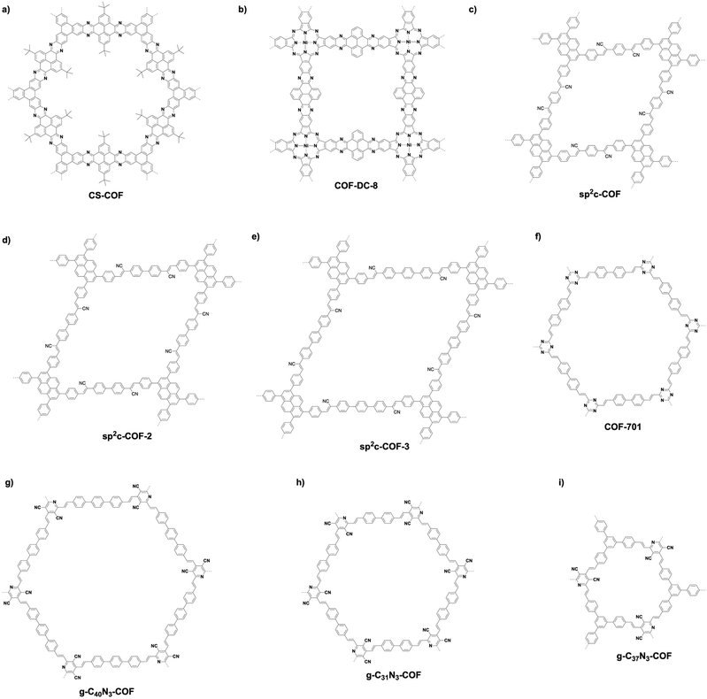
Fully π-conjugated skeletons have been explored using phenazine and C![[double bond, length as m-dash]](https://www.rsc.org/images/entities/char_e001.gif) C bond linkages (Fig. 13). The phenazine linkage is designed by the reaction of a diamine with a diketone. Condensing triphenylene hexamine (TPHA) with tert-butylpyrene tetraone (PT) yields CS-COF (Fig. 15a),304 which is fully π-conjugated and stable due to the fused planar structures. Very recently, phthalocyanine-based phenazine-linked COF-DC-8 (Fig. 15b) has been prepared by condensing 2,3,9,10,16,17,23,24-octaaminophthalocyanine nickel(II) with pyrene-4,5,9,10-tetraone.305 Condensing 2,3,9,10,16,17,23,24-octaaminophthalocyanine with central zinc(II) or copper(II) as a knot and PT as a linker yields MPc-pz COF (M = Zn or Cu).306 Phenazine-linked PGF-1 is prepared by the reaction of 1,2,4,5-benzenetetramine tetrahydrochloride with hexaketocyclohexane octahydrate in the presence of aqueous KOH solution (4 M).307 In order to design and synthesise C
C bond linkages (Fig. 13). The phenazine linkage is designed by the reaction of a diamine with a diketone. Condensing triphenylene hexamine (TPHA) with tert-butylpyrene tetraone (PT) yields CS-COF (Fig. 15a),304 which is fully π-conjugated and stable due to the fused planar structures. Very recently, phthalocyanine-based phenazine-linked COF-DC-8 (Fig. 15b) has been prepared by condensing 2,3,9,10,16,17,23,24-octaaminophthalocyanine nickel(II) with pyrene-4,5,9,10-tetraone.305 Condensing 2,3,9,10,16,17,23,24-octaaminophthalocyanine with central zinc(II) or copper(II) as a knot and PT as a linker yields MPc-pz COF (M = Zn or Cu).306 Phenazine-linked PGF-1 is prepared by the reaction of 1,2,4,5-benzenetetramine tetrahydrochloride with hexaketocyclohexane octahydrate in the presence of aqueous KOH solution (4 M).307 In order to design and synthesise C![[double bond, length as m-dash]](https://www.rsc.org/images/entities/char_e001.gif) C linked COFs, Knoevenagel condensation of aldehydes and benzylnitrile has been explored. sp2c-COF (Fig. 15c) has been synthesised by condensing 1,4-phenylenediacetonitrile with TFPPy in the presence of NaOH.308 Lengthening the linker from phenyl to biphenyl and terphenyl yields sp2c-COF-2 (Fig. 15d) and sp2c-COF-3 (Fig. 15e), respectively.309 Aldol condensation of aldehydes and 2,4,6-trimethyl-1,3,5-triazine or 3,5-dicyano-2,4,6-trimethylpyridine yields C
C linked COFs, Knoevenagel condensation of aldehydes and benzylnitrile has been explored. sp2c-COF (Fig. 15c) has been synthesised by condensing 1,4-phenylenediacetonitrile with TFPPy in the presence of NaOH.308 Lengthening the linker from phenyl to biphenyl and terphenyl yields sp2c-COF-2 (Fig. 15d) and sp2c-COF-3 (Fig. 15e), respectively.309 Aldol condensation of aldehydes and 2,4,6-trimethyl-1,3,5-triazine or 3,5-dicyano-2,4,6-trimethylpyridine yields C![[double bond, length as m-dash]](https://www.rsc.org/images/entities/char_e001.gif) C linked COFs as below. C
C linked COFs as below. C![[double bond, length as m-dash]](https://www.rsc.org/images/entities/char_e001.gif) C linked COF-701 (Fig. 15f) has been prepared by Aldol condensation of 2,4,6-trimethyl-1,3,5-triazine (TMT) with 4,4′-biphenyldicarbaldehyde.310 Condensing TMT with terephthalaldehyde, TFB, naphthalene-2,6-dicarbaldehyde and DMTP forms V-COF-1 (COF-1), V-COF-2, COF-2 and COF-3, respectively.311,312 A series of C
C linked COF-701 (Fig. 15f) has been prepared by Aldol condensation of 2,4,6-trimethyl-1,3,5-triazine (TMT) with 4,4′-biphenyldicarbaldehyde.310 Condensing TMT with terephthalaldehyde, TFB, naphthalene-2,6-dicarbaldehyde and DMTP forms V-COF-1 (COF-1), V-COF-2, COF-2 and COF-3, respectively.311,312 A series of C![[double bond, length as m-dash]](https://www.rsc.org/images/entities/char_e001.gif) C-linked hexagonal g-C40N3-COF (Fig. 15g), g-C31N3-COF (Fig. 15h) and g-C37N3-COF (Fig. 15i) have been synthesised by condensing 3,5-dicyano-2,4,6-trimethylpyridine with 4,4′′-diformyl-p-terphenyl, 4,4′-biphenyldicarbaldehyde and TFP, respectively.19
C-linked hexagonal g-C40N3-COF (Fig. 15g), g-C31N3-COF (Fig. 15h) and g-C37N3-COF (Fig. 15i) have been synthesised by condensing 3,5-dicyano-2,4,6-trimethylpyridine with 4,4′′-diformyl-p-terphenyl, 4,4′-biphenyldicarbaldehyde and TFP, respectively.19
P-StTaDm-COF (Fig. 16a) with fully π-conjugated quinoline linkages has been prepared by a three-component one-pot in situ Povarov reaction between 1,3,5-tris(4-aminophenyl)benzene, DMTPA and styrene (molar ratio = 1![[thin space (1/6-em)]](https://www.rsc.org/images/entities/char_2009.gif) :
:![[thin space (1/6-em)]](https://www.rsc.org/images/entities/char_2009.gif) 1.5
1.5![[thin space (1/6-em)]](https://www.rsc.org/images/entities/char_2009.gif) :
:![[thin space (1/6-em)]](https://www.rsc.org/images/entities/char_2009.gif) 3) in the presence of BF3·OEt2, DDQ, acetic acid and an o-DCB/n-BuOH mixture at 120 °C.30
3) in the presence of BF3·OEt2, DDQ, acetic acid and an o-DCB/n-BuOH mixture at 120 °C.30
Linkage transformation has been developed to construct fully π-conjugated COFs. For example, imine-linked B-COT-1 and T-COF-1 have been prepared by the polycondensation of 2,5-bis(5-methylthiophen-2-yl)benzene-1,4-diamine with TFB and TTB, respectively, under solvothermal conditions. Fully π-conjugated B-COT-2 and T-COF-2 (Fig. 13 and 16b) with fused-aromatic thieno[3,2-c]pyridine linkages were achieved by the cyclisation between the β-carbon of thiophene and the carbon of the imine bond through the Pictet–Spengler reaction.29
Recently, we have explored a template strategy for the synthesis of C![[double bond, length as m-dash]](https://www.rsc.org/images/entities/char_e001.gif) C linked sp2c-COFs (Fig. 17). Using imine-linked COFs as templates in the polycondensation triggers π–π interactions between knot and linker monomers and the knot and linker sites of the surface of the imine-linked skeleton, seeding the C
C linked sp2c-COFs (Fig. 17). Using imine-linked COFs as templates in the polycondensation triggers π–π interactions between knot and linker monomers and the knot and linker sites of the surface of the imine-linked skeleton, seeding the C![[double bond, length as m-dash]](https://www.rsc.org/images/entities/char_e001.gif) C bond formation reaction and guiding the crystallisation and growth of sp2 carbon backbones into the same topological tiling as the template. A key feature of this approach is that it enables the synthesis of sp2c-COFs that cannot be prepared by direct polycondensation. With this method, tetragonal, hexagonal and kagome sp2c-COFs have been designed and synthesised.26 A clear topology effect on π conjugation and exciton migration is observed for sp2c-COFs. The π conjugation and exciton migration progress in the order of kagome > tetragonal ≫ hexagonal lattice (Fig. 18).
C bond formation reaction and guiding the crystallisation and growth of sp2 carbon backbones into the same topological tiling as the template. A key feature of this approach is that it enables the synthesis of sp2c-COFs that cannot be prepared by direct polycondensation. With this method, tetragonal, hexagonal and kagome sp2c-COFs have been designed and synthesised.26 A clear topology effect on π conjugation and exciton migration is observed for sp2c-COFs. The π conjugation and exciton migration progress in the order of kagome > tetragonal ≫ hexagonal lattice (Fig. 18).
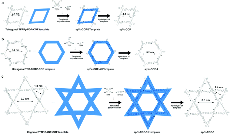 | ||
| Fig. 17 (a) Topology-templated synthesis of tetragonal sp2c-COF using the imine-linked TFPPy-PDA-COF as the template. (b) Topology-templated synthesis of hexagonal sp2-COF-4 using the imine-linked TPB-DMTP-COF as the template. (c) Topology-templated synthesis of kagome sp2-COF-5 using the imine-linked ETTF-DABP-COF as the template. Adapted with permission from ref. 26, Copyright 2020 Wiley-VCH. | ||
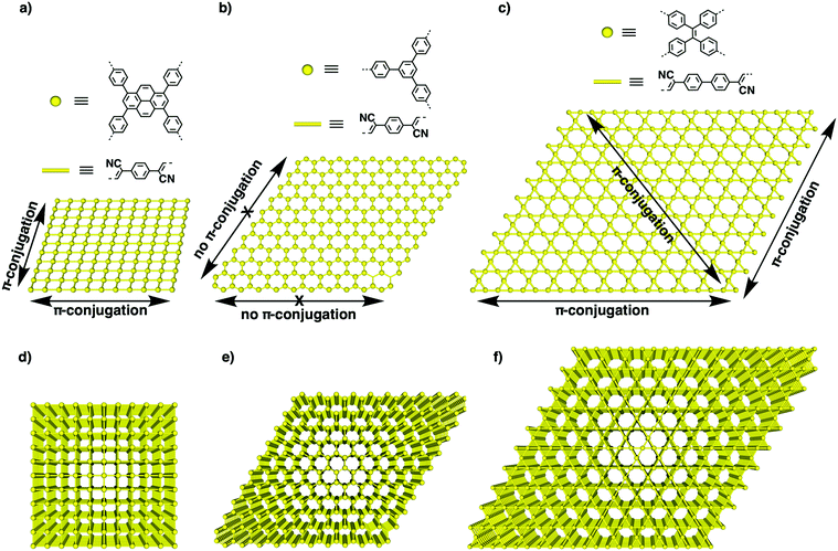 | ||
| Fig. 18 (a–c) The structures of knots and linkers for different topologies and schematics of one-layer 2D lattices of (a) tetragonal, (b) hexagonal and (c) kagome sp2c-COFs. The yellow dots represent knots, while the bars are phenylenevinylene linkers. Arrows show the horizontal transmission of the π cloud in the x–y plane along different directions. (d–f) Schematics of layered structures of (d) tetragonal, (e) hexagonal and (f) kagome sp2c-COFs that enable vertical π overlap along the z direction. Adapted with permission from ref. 26, Copyright 2020 Wiley-VCH. | ||
4. Pores
One of the most fascinating features of COFs is their porous structure. The porous structure of 2D COFs is clearly different from that of 3D COFs. In 2D COFs, the pores are open 1D channels that originate from the stacking of 2D polygonal layers. These channels can be precisely designed and controlled by the monomer structures. In comparison, the pores in 3D COFs are difficult to predict due to the formation of interpenetrated folding structures.76 2D COFs are unique and different from traditional porous materials like zeolites, active carbons, porous silicas, amorphous porous polymers and metal organic frameworks. This is because their 1D channels are independent from each other and can generate isolated nanospaces with regular shapes and well-defined pore walls. The channels create elaborate sites on the pore walls that enable the design of pore environments and interfaces, bringing a promising platform for exploring properties and functions.183,313,3144.1 Pore diversity and control
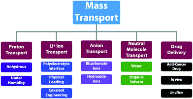
The porosity of COFs has a great influence on their functions and properties. The built-in pores with open apertures on both ends of 1D channels are an ideal platform for mass transportation,282,315–318 gas adsorption and separation,78,101,319 chemical conversion178,320–323 and energy storage.119,324–326 The pore wall is key as it sets the chemical basis for the realisation of functions and determines the local microenvironment and interface for interactions with ions and molecules. The recent progress in chemistry and materials science paves the way for designing and synthesising tailor-made porous structures of COFs. The pore surface engineering strategy marks a big step towards developing tailor-made pores, overcoming the shortages of as-synthesised COFs.157,158,221We have engineered various COFs with different functional groups such as alkyl, alcohol, ester, carboxylic acid and amine units.89 With these distinct porous features, COFs offer an irreplaceable platform for applications in different fields ranging from catalysis to optoelectronics, as well as energy and environmental sciences.
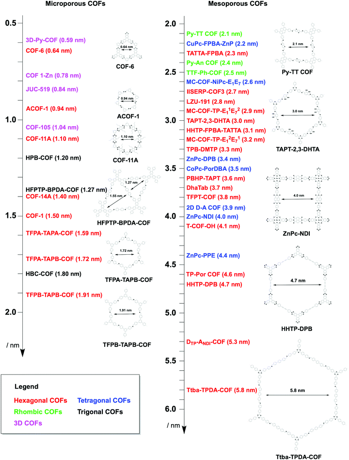
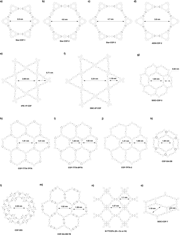
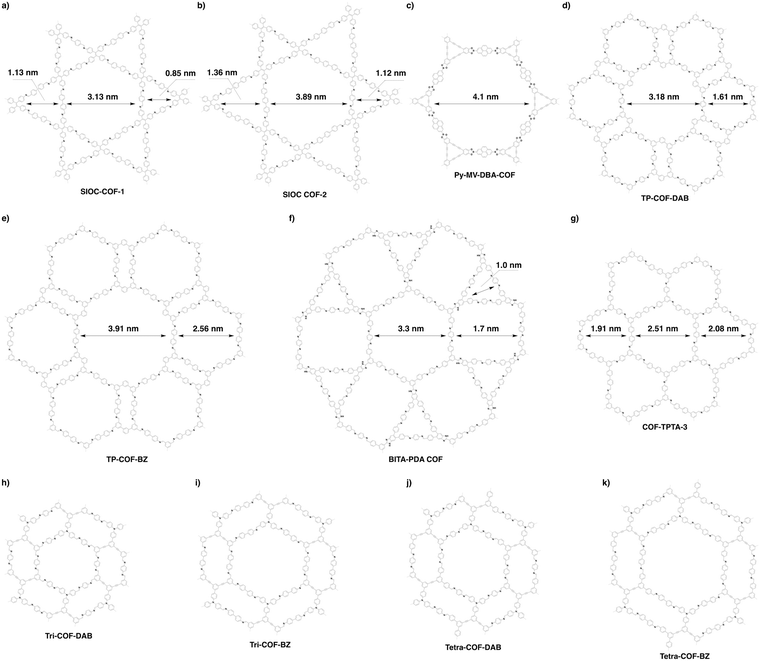
The topology-directed growth of COFs predetermines pore structures including pore shape and size. Delicate design and selection of monomers enable precise control over pore size at atomic accuracy. As shown in Fig. 19, the topology as well as the length of building units regulates the pore size of COFs, i.e. the longer the monomer, the larger the pore.327,328 Thus far, COFs with different sizes ranging from microporous to mesoporous scales have been successfully designed and synthesised.201,266,328,329 Among the reported COFs, COF-6 has the smallest pore (Fig. 20); it is synthesised by condensing HHTP with 1,3,5-benzenetriboronic acid to afford a pore size of 0.64 nm.330 In comparison, the largest pore is 5.8 nm, which is observed for recently developed hexagonal Ttba-TPDA-COF (Fig. 20),331 as well as viologen-linked PC-COF.332 Developing COFs with much smaller or larger pores is highly desired but it remains a substantial challenge; this is a topic worthy of further study. Pore surface engineering leads to the synthesis of small pores, whose shape is difficult to control.
The topology design diagram regulates the growth of COFs with micropores and mesopores. Macroporous COFs (pore size > 50 nm) have not been synthesised thus far, owing to the difficulty of synthesising a unit long enough while still retaining a rigid structure. The topology of COFs has a direct effect on pore size. Generally, COFs with hexagonal, tetragonal and rhombic topological diagrams tend to be mesoporous, while trigonal COFs tend to produce micropores, and kagome COFs offer dual pore structures.
4.2 Micropores
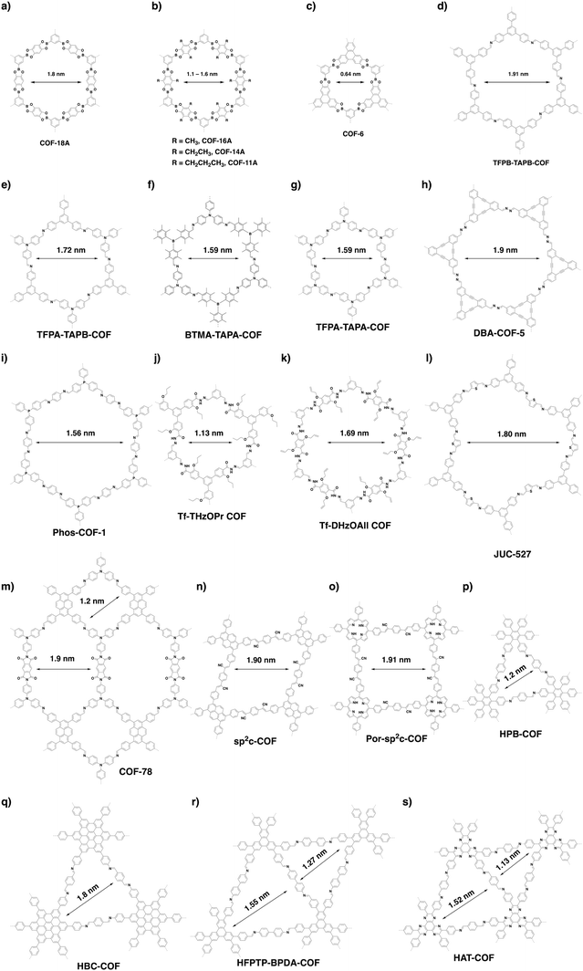
There are limited examples in the family of hexagonal COFs with micropores (Fig. 20). Hexagonal COF-1 (Fig. 14d) synthesised by self-condensation of 1,4-phenyl diboronic acid is a microporous framework with a pore size of 1.5 nm.79 Condensation of 1,2,4,5-tetrahydroxybenzene and benzene-1,3,5-triboronic acid yields COF-18 Å (Fig. 21a), which is microporous with a pore size of 1.8 nm.333 Through a similar strategy, a series of COFs (COF-16 Å, COF-14 Å, COF-11 Å) with 1.6, 1.4 and 1.1 nm micropores have been successfully synthesised by using 2,6-disubstituted 1,2,4,5-tetrahydroxybenzene with methyl, ethyl and propyl substituents, respectively (Fig. 21b).101 A typical microporous COF is COF-6 (Fig. 21c) because it has the smallest pore of 0.64 nm among the COFs without modifications on pore walls.334A delicate predesign of skeletons enables control over the pore size of COFs. For example, we have synthesised four hexagonal COFs (TFPB-TAPB-COF, TFPA-TAPB-COF, BTMA-TATA-COF and TFPA-TAPA-COF) with micropores (Fig. 21d–g) through a careful selection of monomers. The pore size ranges from 1.59 to 1.91 nm.23 Recently, the [C3 + C2] scheme has been developed to synthesise a series of hexagonal COFs with micropores. For example, microporous DBA-COF 5 (Fig. 21h) has been constructed by using dehydrobenzoannulene and hydrazine as building units to yield hexagonal pores of 1.9 nm.31 Based on the same diagram, Phos-COF-1 (Fig. 21i) has been synthesised by condensing tris(4-formylphenyl)phosphine with benzene-1,4-diamine to achieve a honeycomb-shaped micropore of 1.56 nm.36 Tf-THzOPr COF (Fig. 21j) and Tf-DHzOAll COF (Fig. 21k) are two hydrazone-linked COFs with pore sizes of 1.13 and 1.69 nm, respectively.32 JUC-527 (Fig. 21l) with 1.8 nm hexagon-like pores has been synthesised by condensing C3-symmetric 2,4,6-tris(4-aminophenyl)benzene with C2-symmetric 2,5-thiophenedicarboxaldehyde.335 A three-component [C3 + C2 + C2] imine and imide formation reaction between tri(4-aminophenyl)amine, 1,3,6,8-tetrakis(4-formylphenyl)pyrene and pyromellitic dianhydride yields COF-78 (Fig. 21m) with two micropores, of which one is rhombic with a diameter of 1.2 nm and the other is hexagonal with a pore size of 1.9 nm.63
In addition to the [C3 + C2] combination, other topology diagrams have been developed to design microporous COFs. We have explored a topology-templated synthesis of sp2c-COFs using the [C2 + C2] combination. Concretely, imine-linked TFPPy-PDA-COF has been selected as the template to allow the in situ growth of crystalline sp2c-COF (Fig. 15c and Fig. 21n). The resulting C![[double bond, length as m-dash]](https://www.rsc.org/images/entities/char_e001.gif) C linked sp2c-COF condensed from C2-symmetric 1,4-phenylenediacetonitrile and 1,3,6,8-tetrakis(p-formylphenyl)pyrene is rhombic with a uniform pore size of 1.9 nm.26 Through the [C4 + C2] topological scheme, another C
C linked sp2c-COF condensed from C2-symmetric 1,4-phenylenediacetonitrile and 1,3,6,8-tetrakis(p-formylphenyl)pyrene is rhombic with a uniform pore size of 1.9 nm.26 Through the [C4 + C2] topological scheme, another C![[double bond, length as m-dash]](https://www.rsc.org/images/entities/char_e001.gif) C linked COF (Por-sp2c-COF) (Fig. 21o) has been synthesised using the Knoevenagel condensation of 1,4-phenylenediacetonitrile with 5,10,15,20-tetrakis(4-benzaldehyde)porphyrin. Por-sp2c-COF has tetragonal micropores with a size of 1.91 nm.49
C linked COF (Por-sp2c-COF) (Fig. 21o) has been synthesised using the Knoevenagel condensation of 1,4-phenylenediacetonitrile with 5,10,15,20-tetrakis(4-benzaldehyde)porphyrin. Por-sp2c-COF has tetragonal micropores with a size of 1.91 nm.49
In contrast, the [C6 + C2] strategy generates a triangular topology, with which it is much easier to create microporous COFs. It integrates the highest density of aromatic building units into the scaffolds to form the smallest pore among all the topologies. We have developed the trigonal strategy for synthesising two microporous COFs by condensing a C2-symmetric linker with two different C6-symmetric knots.48 The condensation of hexakis(4-aminophenyl)benzene with terephthalaldehyde forms HPB-COF (Fig. 21p) with a pore size of 1.2 nm, while reaction of amino-substituted hexabenzocoronene with terephthalaldehyde yields HBC-COF (Fig. 21p) with a 1.8 nm sized pore. These trigonal COFs constitute an isotopic tiling so that the triangular pores are distributed uniformly across the material. Recently, we have developed triangular COFs that contain two micropores with different sizes.314 This strategy retains the number of reactive groups but lowers the symmetry from C6 to C3 to fulfil the [C3 + C2] diagram, which produces dual-pore HFPTP-BPDA-COF (Fig. 21r) with large (1.55 nm) and small pores (1.27 nm).314 A similar triangular COF, HAT-COF (Fig. 21s), with two micropores with sizes of 1.52 and 1.13 nm, has been synthesised using the [C3 + C2] diagram.336
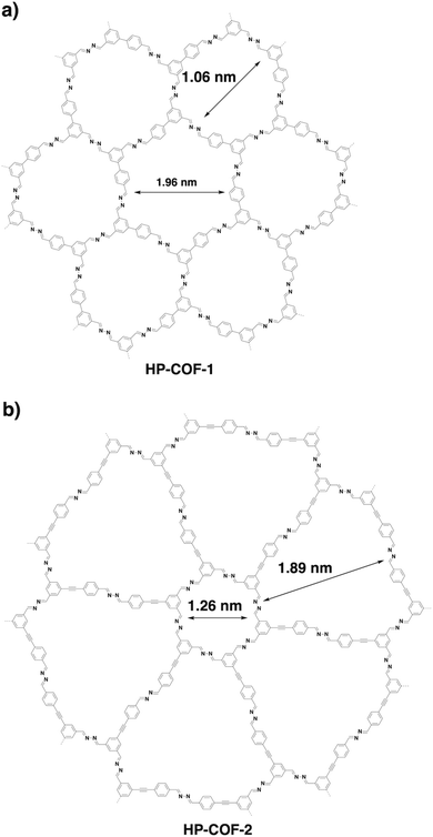
Through a desymmetrised vertex design scheme, HP-COF-1 (Fig. 22a) and HP-COF-2 (Fig. 22b) with heterogeneous hexagonal micropores have been synthesised.337 HP-COF-1 containing two hexagonal micropores is synthesised from 5-(4-formylphenyl)-isophthalaldehyde and hydrazine. The small pore is 1.06 nm, while the large one is 1.96 nm. Condensing 5-((4-formylphenyl)ethylene)-isophthalaldehyde with hydrazine yields HP-COF-2, which possesses a large micropore of 1.89 nm and a small one of 1.26 nm.
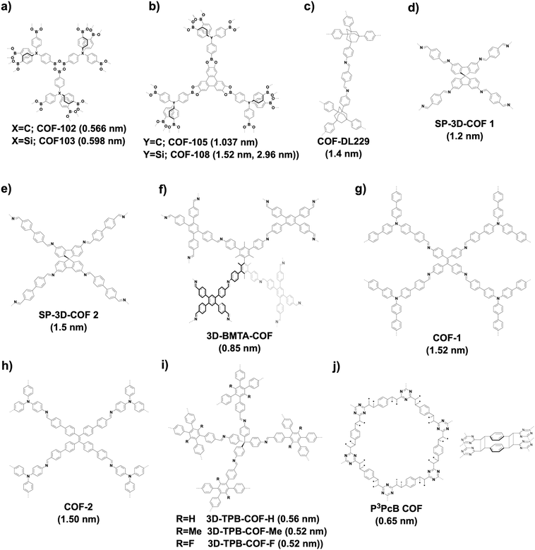
3D COFs tend to produce microporous structures.70 Microporous COF-102 and COF-103 (Fig. 23a) are constructed based on the [Td + Td + Td] strategy by self-condensation of Td-symmetric tetra(4-dihydroxyborylphenyl)methane and tetra(4-dihydroxyborylphenyl)silane, respectively, to form a ctn network. Condensing Td-symmetric tetra(4-dihydroxyborylphenyl)methane or tetra(4-dihydroxyborylphenyl)silane with C3-symmetric HTTP based on the [Td + C3] diagram yields COF-105 or COF-108 (Fig. 23b), respectively. COF-105 is a ctn net and COF-108 assumes a bor network. The pore size of COF-102, COF-103 and COF-105 is 0.566, 0.598 and 1.037 nm, respectively, while COF-108 possesses two different pores with sizes of 1.52 and 2.96 nm. Using an orthogonal monomer and lowering the C3-symmetric monomer to a C2-symmetric monomer for the condensation to afford a [Td + C2] diagram yields an imine-linked 3D COF-DL229 (Fig. 23c),103 which possesses a dia topology and an eightfold interwoven skeleton and forms ordered 1D channels 1.4 nm in window.
Recently, the spirobifluorene unit has been developed as a new 3D knot to build 3D COFs. For example, SP-3D-COF 1 and SP-3D-COF 2 (Fig. 23d and e) have been synthesised by condensing 3,3′,6,6-tetraamine-9,9-spirobifluorene with 1,4-phthalaldehyde and 4,4′-biphenyldicarbaldehyde, respectively.338 The pore size of SP-3D-COF 1 and SP-3D-COF 2 is 1.2 and 1.5 nm, respectively.
Interestingly, by twisting the building unit from planar to tetrahedral, imine-linked 3D-BMTA-COF (Fig. 23f) has been constructed by condensing 1,2,4,5-tetrakis(4-formylphenyl)-benzene with 3,3′,5,5′-tetra(p-aminophenyl)-bimesitylene (BMTA). The 3D BMTA knot is formed by introducing methyl groups at ortho positions in the biphenyl backbone to generate a dihedral angle of 60°. The 3D-BMTA-COF shows a seven-fold interpenetrated pts topology with a pore size of 0.85 nm.69 In contrast, 3D COF-1 (Fig. 23g) and COF-2 (Fig. 23h) are less folded and adopt a two-fold interpenetration with an ffc topology. 3D COF-1 with a pore size of 1.52 nm has been synthesised using tetrakis(4-aminophenyl)ethene and 4,4′,4′′-[nitrilotris(4,1-phenylene)]trisbenzaldehyde as monomers, while 3D COF-2 has been constructed by condensing tris(4-aminophenyl)amine with 4′,4′′′,4′′′′′,4′′′′′′′-(ethene-1,1,2,2-tetrayl)tetrakis(biphenyl-4-carbaldehyde) and shows a pore size of 1.50 nm.339 A series of imine-linked microporous 3D COFs (Fig. 23i) have been developed by using tetra(p-aminophenyl)methane as a 3D knot and 1,2,4,5-tetraphenylbenzene with different substituted groups at the 3- and 6-positions as linkers. In detail, three derivatives of 1,2,4,5-tetraphenylbenzene with H, Me and F substituents generate 3D-TPB-COF-H, 3D-TPB-COF-Me and 3D-TPB-COF-F, which have pore sizes of 0.56, 0.52 and 0.52 nm, respectively.67 2D P2PV COF can be converted to 3D P3PcB COF (Fig. 23j) upon irradiation with a halogen lamp for seven days. This structural transformation is realised by photoinduced [2+2] cycloaddition of vinylene-linked phenylenevinylene, so that a new pore centred at 0.65 nm appears in P3PcB COF.260
Although various microporous COFs are available, their diversity is quite limited compared to their mesoporous counterparts. How to break the limitations of building blocks to enhance the family of microporous COFs is still challenging. The pore surface engineering strategy is regarded as a promising approach that tailors the pore size with desired diameter but how to create discrete pore shapes through post-synthetic modification is an interesting issue worthy of further effort.
4.3 Mesopores
Organic π units usually have a size over several Å or 1 nm; this is the reason why COFs tend to form mesoporous structures. Tetragonal, hexagonal and rhombic topologies generally yield mesoporous COFs (Fig. 20).340 The development of a mixed linker strategy,56 double-stage strategy,58 multicomponent strategy62 and desymmetrised vertex strategy337 has proven to be effective for the preparation of irregularly-shaped hexagonal, tetragonal, rhombic and kagome pores, with up to three different pore sizes in one COF.56,341Among the strategies for designing hexagonal COFs, the [C3 + C2] diagram has been widely used for the synthesis of mesoporous structures. To design the pore size of hexagonal COFs, the knot structure is usually a C3-symmetric unit, which is largely based on triphenylene, triphenylbenzene and triphenylamine backbones, while the linker unit adopts a C2 symmetry, including phenyl, diphenyl, terphenyl, pyrene, thiophene, thienothiophene and porphyrin derivatives. Various linkages have been developed for the synthesis of mesoporous hexagonal COFs, including boronate ester, imine, hydrazone, phenazine, imide, azine, β-ketoenamine-linked, squaraine, C![[double bond, length as m-dash]](https://www.rsc.org/images/entities/char_e001.gif) C bond and dioxin linkages (refer to Section 3 Skeletons).
C bond and dioxin linkages (refer to Section 3 Skeletons).
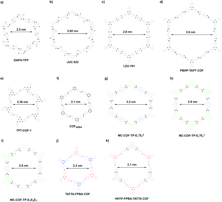
β-Ketoenamine-linked DAPH-TFP (Fig. 24a) and JUC-523 (Fig. 24b) have been designed using the [C3 + C2] topology diagram to yield hexagonal pores with sizes of 2.5 and 2.92 nm, respectively.342,343 The largest pore is 5.8 nm, which is observed for recently developed imine-linked Ttba-TPDA-COF condensed from C3-symmetric triamine and C2-symmetric terphenyldicarbaldehyde,331 as well as viologen-linked PC-COF.332
Besides direct synthesis, post-synthetic transformation of linkages has been developed for the synthesis of mesoporous hexagonal COFs. For example, benzoxazole-linked LZU-191 (Fig. 24c) with a pore size of 2.8 nm is constructed via a cascade reaction of imination, cyclisation and oxidation.322 Michael addition followed by elimination yields β-amino enone linked PBHP-TAPT COF (Fig. 24d), which has a pore size of 3.6 nm.344
The [C3 + C3] topology diagram tends to yield microporous hexagonal structures.23,261 Nevertheless, imine-linked TPT-COF-1 (Fig. 24e) constructed from flexible C3-symmetric triaryloxytriazine units possess a 2.36 nm sized pore.345 Likewise, the [C2 + C2 + C2] topology mostly produces microporous hexagonal structures: for example, the self-condensation of boronic acids to boroxine rings267 and trimerisation of nitriles to triazine-based frameworks.294 However, if the building unit is long enough, the synthesis of mesoporous COFs becomes possible. One example is diazo COFABBA (Fig. 24f), which is self-condensed from 4,4′-phenylazobenzoyl diboronic acid and has a mesopore of 2.1 nm.346
The scope of hexagonal pores is greatly expanded by the development of the multicomponent strategy. Using one knot and two different linkers, either MC-COF-TP-E11E27 (Fig. 24g) or MC-COF-TP-E21E17 (Fig. 24h) is selectively prepared by tuning the monomer ratio. The two COFs have aligned irregular hexagonal 1D pores with sizes of 3.2 nm and 2.9 nm, respectively. On the other hand, using one knot and three different linkers to generate MC-COF-TP-E1E3E7 (Fig. 24i) forms a uniform pore of 2.9 nm.62 The double-stage approach has been explored using a C1-symmetric heterodifunctionalised unit as a building block to install two different linkages, greatly increasing the diversity of hexagonal pores. For example, TATTA-FPBA COF (Fig. 24j) and HHTP-FPBA-TATTA COF (Fig. 24k) are designed using [C3 + C1] and [C3 + C1 + C3] topology diagrams to yield irregular hexagonal pores with sizes of 2.3 and 3.1 nm, respectively.58
The [C4 + C2] and [C4 + C4] topology schemes enable the design of tetragonal skeletons, which exhibit extended π conjugation in both the x and y directions, and are in sharp contrast to the hexagonal topology with only limited π cloud delocalisation. Owing to the intrinsic C4-symmetry, porphyrin and phthalocyanine units are typical building blocks for the construction of tetragonal COFs.
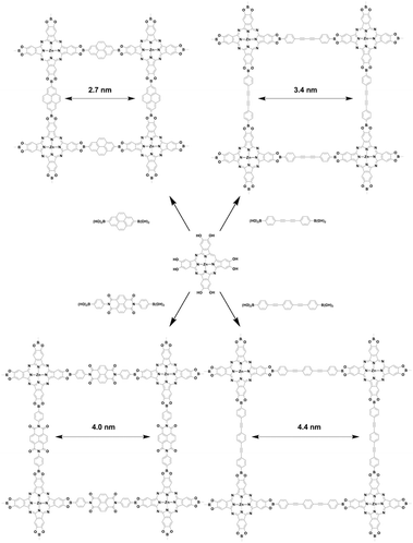
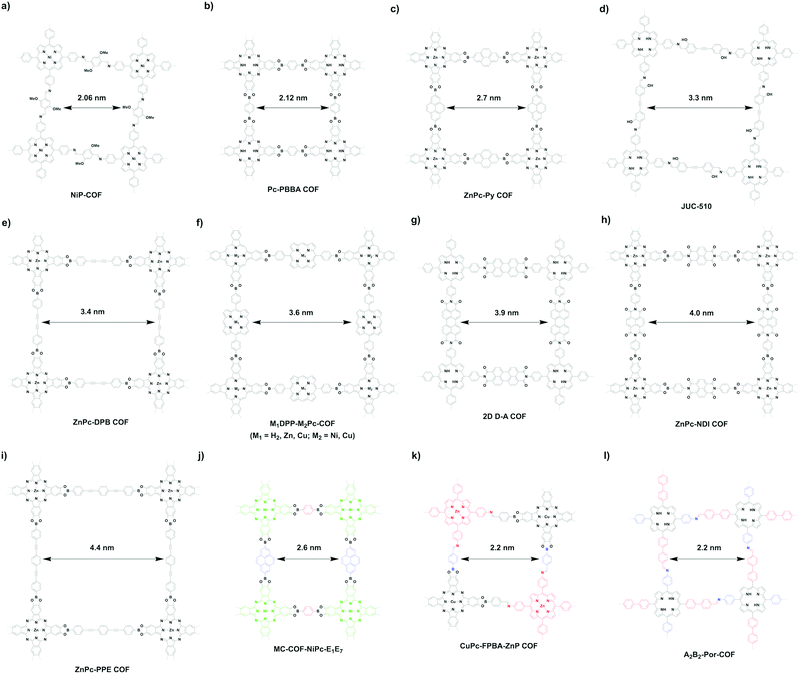
The [C4 + C2] topology diagram usually yields mesopores. For example, imine-linked porphyrin-based NiP-COF (Fig. 25a) possesses a relatively small mesopore with a size of 2.06 nm,125 while Pc-PBBA COF (Fig. 25b) has a similar pore size of 2.1 nm.41 Slightly longer pyrene-containing ZnPc-Py COF (Fig. 25c) has a pore size of 2.7 nm,347 while extension with an acetylene further increases the pore size to 3.3 nm in imine-linked JUC-510 (Fig. 25d).348 As the acetylene is changed to the diacetylene group in ZnPc-DPB COF (Fig. 25e),347 the pore size is increased to 3.4 nm. By combining C4-symmetric phthalocyanine and C2-symmetric porphyrin, porphyrin-co-phthalocyanine COFs (Fig. 25f) with pore sizes of 3.6 nm have been prepared.44 The perylenediimide-based donor–acceptor 2D D–A COF (Fig. 25g) has a pore size of 3.9 nm,349 while the naphthalenediimine-based ZnPc-NDI COF (Fig. 25h) has a similar pore size of 4.0 nm.347 A pore size of 4.4 nm is achieved with ZnPc-PPE COF (Fig. 25i) as the linker is further extended.347
Similar to the [C4 + C2] topology, the [C4 + C4] topology is expected to generate mostly microporous COFs, while mesoporous COFs remain to be explored. Mesoporous pores become possible via a one-knot-two-linker multicomponent approach. For example, MC-COF-NiPc-E1E7 (Fig. 25j) with a phthalocyanine knot and two different linkers yields a rectangle pore of 2.6 nm.62 The double-stage approach forms CuPc-FPBA-ZnP-COF (Fig. 25k) with a pore size of 2.2 nm.58 Interestingly, a bifunctionalised porphyrin monomer upon self-condensation forms A2B2-Por-COF (Fig. 25l), which has a 2.2 nm tetragonal pore.166
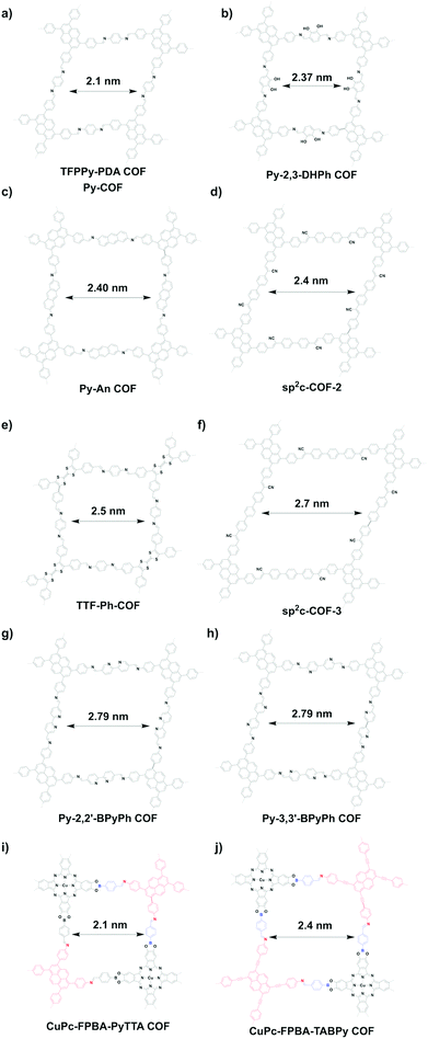
The rhombic topology has a low symmetry compared to the tetragonal topology. Rhombic COFs can only be designed using the [C2 + C2] topology diagram. Interestingly, this topology diagram forms dual-pore kagome structures. One common monomer for the design of rhombic pores is the tetraphenyl substituted pyrene unit, which upon condensation with the appropriate linkers produces rhombic pores in the mesoporous range. This is exemplified by imine-linked TFPPy-PDA-COF (Fig. 26a) with a pore size of 2.1 nm.26 In another example, catechol-functionalised Py-2,3-DHPh COF (Fig. 26b) has a pore size of 2.37 nm.244 On the other hand, imine-linked Py-An COF (Fig. 26c) has a pore size of 2.40 nm,350 similar to sp2c-COF-2 (Fig. 26d).309 Interestingly, condensing C2-symmetric tetrathiafulvalene (TTF) with C2-symmetric 1,4-phenyldiamine produces TTF-Ph-COF with a pore size of 2.5 nm (Fig. 26e).288 The use of terphenyl linkers produces sp2c-COF-3 (Fig. 26f) with 2.7 nm sized pores,309 while bipyridine-containing Py-2,2′-BPyPh COF (Fig. 26g) and Py-3,3′-BPyPh COF (Fig. 26h) have pore sizes of 2.79 nm.244
Using the double-stage strategy with C4-symmetric phthalocyanine, a C1-symmetric bifunctional linker and C2-symmetric blocks as monomers, two rhombic COFs, i.e. CuPc-FPBA-PyTTA COF (Fig. 26i) and CuPc-FPBA-TABPy COF (Fig. 26j), have been synthesised with pore sizes of 2.1 and 2.4 nm, respectively. Although a distorted geometry is imposed by the unmatched angles, the rhombic COFs have good crystallinities.58
4.4 Multiple pores
Compared to single pore COFs, heteropore COFs with hierarchical pores extend the scope and diversity of structures. We divide all the heteropore COFs reported so far into dual-pore (Fig. 27) and multi-pore COFs (Fig. 28). The first dual-pore COFs (Fig. 27a) have been explored by condensing a C3-symmetric phenanthrene cyclotrimer macrocycle with a C2-symmetric linker to form star-COF-1, star-COF-2 and star-COF-3, to form kagome shapes with dual pores, where the hexagonal pores ranges from 3.9 to 4.7 nm (Fig. 29a–c).51 Similarly, AEM-COF-2 (Fig. 29d),351 DAB-COF-1 and DAB-COF-252 have been synthesised from C3-symmetric π-conjugated AEM-2, DBA[12] and DBA[18] monomers and C2-symmetric 1,4-benzenediboronic acid (BDBA) monomer to generate pore sizes of 3.8, 3.2 and 3.6 nm, respectively. Kagome (Fig. 27b) 2D dual-pore 4PE-1P COF bearing a trigonal micropore of 0.71 nm and a hexagonal mesopore of 2.69 nm has been constructed via the condensation of two C2-symmetric building blocks (Fig. 29e).54 In this case, the formation of the dual-pore kagome COF is attributed to the energy difference large enough between the dual pore and one-pore rhombic COFs under solvothermal conditions.Other kagome COFs (including TPE-Ph COF;55 DBC-2P COF (Fig. 29f);352 4PE-TT COF and 4PE-BDT COF;281 ETTA-TPA COF21 and Etta-Td COF;353 Per-1P, Per-N and Per-Py COFs;218 and TA DBC-COF, Biph DBC-COF and TT DBC-COF)354 have been developed by using a variety of different linkages. The [C3 + C2] topology can be used to construct dual-triangular pore COFs (Fig. 27c). For example, HAT-COF (Fig. 21s) is prepared by condensing C3-symmetric HAT-6NH2 with terephthalaldehyde to generate two triangular micropores with sizes of 1.13 and 1.52 nm.290 Recently, our group has developed dual-triangular pore HFPTP-BPDA-COF (Fig. 21r) with pore sizes of 1.27 and 1.55 nm for molecular recognition and capture.314 Through a desymmetrised knot strategy (Fig. 27d), HP-COF-1 and HP-COF-2 (Fig. 22) with high surface areas and dual pore structures are successfully synthesised by condensing a C2-symmetric knot with a linear hydrazine linker.337 Bifurcation of each end of a C3-symmetric knot increases the number of linking sites, allowing the generation of a dual-pore topology (Fig. 27e). SIOC-COF-3 (Fig. 29g) and SIOC-COF-4 have been prepared via this strategy. Although low crystallinity was observed, SIOC-COF-3 is expected to have pore sizes of 1.84 and 0.82 nm.355 The [C3 + C2] diagram (Fig. 27f) yields dual-pore COFs such as COF-TTTA-TPTA (Fig. 29h) and COF-TTTA-BPTA (Fig. 29i) by condensing TTTA with BPTA and TPTA.356 The use of two C2v-symmetric building blocks (Fig. 27g) affords COF-TPTA-2 (Fig. 29j) with pore sizes of 1.41 and 1.68 nm.357
The orthogonal strategy (Fig. 27h) is an effective way for the construction of dual-pore COF-DA-DB (Fig. 29k) and COF-OEt (Fig. 29l) by imine or hydrazone formation and trimerisation of boronic acids. Notably, the COFs have hexagonal pore sizes of 1.84 and 2.35 nm, respectively, while the rectangular pores are too narrow to be measured by nitrogen sorption.61,358 Through a multicomponent double-stage approach (Fig. 27i), COF-DA-DB-TB (Fig. 29m) containing both imine and boronate ester linkages can be prepared. COF-DA-DB-TB has pore sizes of 1.52 and 1.28 nm.358 The [C2 + C2] strategy (Fig. 27j) can be used to synthesise dual-pore COFs. For example, SIOC-COF-5 and SIOC-COF-6 with two different pores are produced through the condensation reactions of ETTA with BTA or BDTB, leading to pore sizes of 0.65 and 1.13 and 1.02 and 1.66 nm, respectively.359 A similar strategy generates a dual-pore tetragonal structure. For example, imine-linked M-TTCOFs (M = Co and Ni) (Fig. 29n) have been constructed by condensing tetrathiafulvalene with metalloporphyrins to form two rhombic pores with sizes of 1.1 and 1.57 nm.360 Integrating extra linking sites into the monomer is possible to construct dual pore COFs (Fig. 27k). The condensation of C2-symmetric BFATD bearing six aldehyde groups, two in the middle and four at the end, with 1,4-diaminobenzene yields dual-pore SIOC-COF-7 (Fig. 29o) with pore sizes of 0.5 and 1.19 nm.102 Two spiroborate ICOF-1 and ICOF-2 with square pores are synthesised by the same strategy to form 1.1 and 2.2 nm pores.361
A mixed linker strategy has been developed (Fig. 28a) for the construction of SIOC-COF-1 (Fig. 30a) with 0.85, 1.13 and 3.13 nm pores and SIOC-COF-2 (Fig. 30b) with 1.12, 1.36 and 3.89 nm pores, by condensing a C2-symmetric tetraamine and two C2-symmetric dialdehydes with different lengths.56 The same strategy has been applied for the construction of multi-pore COFs (Fig. 28b). Through the simultaneous condensation of linear monomer PDBA with two cyclic monomers DBA[12] and DBA[18], Py-MV-DBA-COF (Fig. 30c) containing three different pores of 0.394 nm (from simulation), 0.542 nm (from simulation) and 4.1 nm (from its nitrogen sorption isotherm) has been synthesised.53 Reducing the symmetry of knots produces triple-pore COFs (Fig. 28c). For example, TP-COF-DAB (Fig. 30d) with triple pores with sizes of 0.32 nm (from simulation), 1.61 nm (from nitrogen sorption isotherms) and 3.18 nm (from nitrogen sorption isotherms) have been synthesised by condensing a V-shaped building block with two aldehyde linkers.341 By a similar approach, TP-COF-BZ (Fig. 30e) with triple pores with sizes of 0.32 nm (from simulation), 2.56 nm (from nitrogen sorption isotherms) and 3.91 nm (from nitrogen sorption isotherms) has been prepared.341 A novel 2D imine-based COF, i.e. BITA–PDA COF (Fig. 30f) with 1.0, 1.7 and 3.3 nm pores, has been synthesised by condensing a desymmetrised rigid tetraaldehyde BITA with well-defined vertex angles of 60, 90 and 120° and a linear diamine linker (Fig. 28d).362 The use of two C2v-symmetric building blocks with different lengths (Fig. 28e) affords COF-TPTA-3 (Fig. 30g) containing three pores with sizes of 1.91, 2.08 and 2.51 nm.357 Bifurcation of each end of a C3-symmetric knot followed by desymmetrisation allows the formation of triple-pore 2D COFs (Fig. 28f), Tri-COF-DAB (Fig. 30h) and Tri-COF-BZ (Fig. 30i), while further desymmetrisation using a C1-symmetric knot (Fig. 28g) creates tetra-pore 2D COFs, i.e. Tetra-COF-DAB (Fig. 30j) and Tetra-COF-BZ (Fig. 30k). However, the pore sizes of these flexible COFs cannot be calculated from pore size distribution (PSD) analysis, owing to no suitable model matching these highly complex COFs, but the results of PXRD and HR-TEM support the multiple pores.363
4.5 Pore interface design
Pore surface engineering is a powerful strategy for the functionalisation of pore walls as it enables the integration of various functional groups onto the pore walls to achieve desirable units, components and densities.221,364 This strategy opens the way to tailor-made pore environments and pore wall interfaces.365,366 A diversity of functionalities including alkyl chains, hydroxy groups, amino units, carboxylic acid moieties, organic radical species and catalytic sites have been introduced onto pore walls via pore surface engineering (refer to Section 2.7 Post-synthetic functionalisation units). Besides pore surface engineering, pore walls have been functionalised by using the following two methods: (1) condensation with functionalised monomers and (2) coordination with metal ions (Scheme 4). Although linkage transformation can induce new interactive sites on pore walls, the methodology itself is developed for skeleton modification other than porous structural control.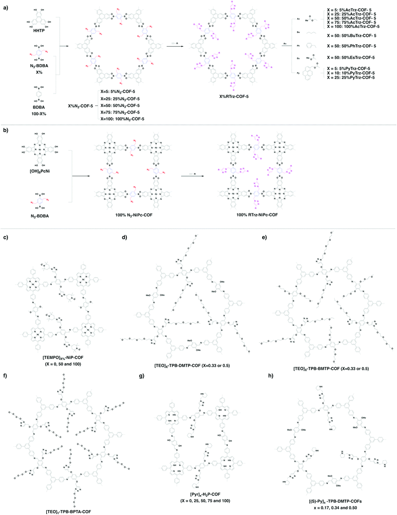 | ||
| Fig. 31 Pore surface engineering of (a) X%N3-COF-5 and (b) 100% N3-NiPc-COF. (c–h) Representative examples of post-synthetic modified COFs from azide–alkyne click reaction. | ||
COFs have been installed with redox activity by incorporating electron-unpaired organic radicals onto the pore walls via pore surface engineering. For example, the stable organic radical (2,2,6,6-tetramethyl-1-piperidin-1-yl)oxyl (TEMPO) has been integrated onto the pore walls to yield [TEMPO]50%-NiP-COF and [TEMPO]100%-NiP-COF quantitatively, following a click reaction between ethynyl groups and 4-azido-(2,2,6,6-tetramethyl-1-piperidin-1yl)oxyl (Fig. 31c).125 We have reported a strategy for systematically tuning polyelectrolyte interfaces in the 1D channels of COFs, based on pore surface engineering, with the aim of achieving ultrafast ion transport. The resulting five new COFs, [TEO]0.33-TPB-DMTP-COF, [TEO]0.5-TPB-DMTP-COF, [TEO]0.33-TPB-BMTP-COF, [TEO]0.5-TPB-BMTP-COF and [TEO]1-TPB-BPTA-COF (Fig. 31d–f), have been prepared by integrating tetra(ethylene oxide) polyelectrolyte units (TEO; C8H17O4) onto the pore walls via click reaction between ethynyl units and 13-azido-2,5,8,11-tetraoxatridecane. The TEO units are precisely installed on the pore walls of TPB-DMTP-COF and TPB-BMTP-COF. The polyelectrolyte interface is key to ion transport.367
We have reported the first chiral [Pyr]X-H2P-COF (X = 0, 25, 50, 75 and 100) (Fig. 31g) with different densities of catalytic sites on the pore walls via click reaction of alkynyl groups with chiral pyrrolidine units. The resulting COFs are chiral and serve as heterogeneous organocatalysts for the Michael addition reaction.157 Similarly, crystalline mesoporous TPB-DMTP-COF (TPB, triphenylbenzene; DMTP, dimethoxyterephthalaldehyde) is synthesised by introducing two electron-donating methoxy groups into linkers which trigger a resonance effect on the central phenyl ring to weaken the polarisation of the C![[double bond, length as m-dash]](https://www.rsc.org/images/entities/char_e001.gif) N bonds and soften the interlayer charge repulsion and consequently stabilise the skeleton. TPB-DMTP-COF is stable against boiling water, strong acids and strong bases. Pore surface engineering of [HC
N bonds and soften the interlayer charge repulsion and consequently stabilise the skeleton. TPB-DMTP-COF is stable against boiling water, strong acids and strong bases. Pore surface engineering of [HC![[triple bond, length as m-dash]](https://www.rsc.org/images/entities/char_e002.gif) C]X-TPB-DMTP-COFs (X = 0, 0.17, 0.34 and 0.50) via a three-component condensation system followed by click reaction yields chiral organocatalytic [(S)-Py]X-TPB-DMTP-COFs (Fig. 31h). This strategy enables the design of stable crystalline and porous COFs to achieve a variety of properties and functions.158
C]X-TPB-DMTP-COFs (X = 0, 0.17, 0.34 and 0.50) via a three-component condensation system followed by click reaction yields chiral organocatalytic [(S)-Py]X-TPB-DMTP-COFs (Fig. 31h). This strategy enables the design of stable crystalline and porous COFs to achieve a variety of properties and functions.158
Besides azide–alkyne click reaction, a wide variety of other reactions have been reported to modify the pore walls of COFs. It is possible to apply the pore surface engineering strategy to introduce different radical units to control the pore surface. A cationic radical COF (Py-BPy+˙-COF) has been constructed by the sequential transformation of neutral 2,2′-bipyridine Py-BPy-COF via quaternisation and one-electron reduction. As a result of electronic delocalisation over the 2D layer and long-distance uniaxial interlayered π-electronic coupling, Py-BPy+˙-COF enhances photothermal conversion, which is promising for photothermal therapy and photoacoustic imaging in vivo (Fig. 32a).46
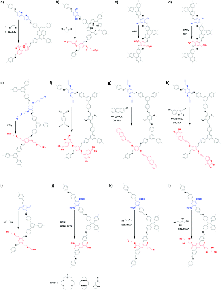 | ||
| Fig. 32 Representative examples of post-synthetic modification reactions. Only repetitive parts are shown for clarity. | ||
We have developed a series of [HO2C]X%-H2P-COFs (X = 25, 50, 75 and 100) with different densities of carboxylic groups, which are controlled by the content of phenol groups of [HO]X%-H2P-COFs (X = 25, 50, 75 and 100) via a ring opening reaction between phenol groups and succinic anhydride (Fig. 32b). Interestingly, the CO2 uptake capacity is proportional to the content of carboxylic groups. These results suggest that pore surface engineering with carboxylic groups can efficiently enhance the CO2 adsorption.368 The chemical stability of COFs is one key parameter for practical application; stability can be improved via pore surface engineering. For example, crystalline, porous and stable polyarylether-based JUC-505 and JUC-506 have been synthesised through nucleophilic aromatic substitution reactions to form ether linkages. After post-synthetic modification, JUC-505-COOH (Fig. 32c) and JUC-505-NH2 (Fig. 32d) possess carboxyl or amino functional groups and are stable against boiling water, strong acids and strong bases and under harsh redox (chromic acid solution and LiAlH4) conditions. These carboxylic or amino functionalised COFs remove antibiotics from water over a wide pH range from 1 to 13.270
The imine-linked X%[NH2]-COFs (X = 0, 1, 10, 20, 28, 50, 75 and 100) have been synthesised by reducing the X%[N3]-COFs (X = 0, 1, 10, 20, 28, 50, 75 and 100) with PPh3 in CH3OH (Fig. 32e). The X%[N3]-COFs are constructed by condensing 1,3,5-tris(4-aminophenyl)benzene monomer with a mixture of dialdehyde bearing azide units and terephthalaldehyde. The X%[NH2]-COFs remove GenX and perfluorinated alkyl substances (PFAS) at environmentally relevant concentrations.99
The electronic behaviour and redox activity of crystalline COFs can be controlled by forming donor–acceptor alignment via pore surface engineering. Recently, [HC![[triple bond, length as m-dash]](https://www.rsc.org/images/entities/char_e002.gif) C]X%-TPB-DMTP-COFs (X = 0, 34, 50, 100) have been selected as a platform to covalently decorate their alkyne groups with bulky fullerene (C60) and planar tetracyanoquinodimethane (TCNQ) electron acceptors via 1,3- and [2+2] cycloadditions (Fig. 32f), respectively. The C60-linked COFs increase the conductivity by eight orders of magnitude compared to the bare TPB-DMTP-COF. The fluorophore tags 6-bromo-3-cyano-4-methylcoumarin and 2-bromoanthracene, which react with alkyne groups on the pore walls via the Sonogashira reaction (Fig. 32g and h), have been developed to monitor the reaction process in the COFs, based on the change in fluorescence signal.369
C]X%-TPB-DMTP-COFs (X = 0, 34, 50, 100) have been selected as a platform to covalently decorate their alkyne groups with bulky fullerene (C60) and planar tetracyanoquinodimethane (TCNQ) electron acceptors via 1,3- and [2+2] cycloadditions (Fig. 32f), respectively. The C60-linked COFs increase the conductivity by eight orders of magnitude compared to the bare TPB-DMTP-COF. The fluorophore tags 6-bromo-3-cyano-4-methylcoumarin and 2-bromoanthracene, which react with alkyne groups on the pore walls via the Sonogashira reaction (Fig. 32g and h), have been developed to monitor the reaction process in the COFs, based on the change in fluorescence signal.369
The nanochannels of 2D COFs have a great possibility of selectively transporting molecules, ions and biomolecules, via post-synthetic modification of pore walls with functional groups. For example, two 2D mesoporous COFs, i.e., AA stacked CD-COF-1 and AB stacked CD-COF-2, have been synthesised by decorating chiral β-cyclodextrin (β-CD) via thiol–ene click reaction on the pore walls of COF-1 and COF-2, respectively. The resulting CD-COFs are utilised to fabricate mixed matrix membranes for selective transport of amino acids. The AA stacked CD-COF-1 with uniform open nanochannels displays a chiral selectivity in recognition of L-histidine.370 Similarly, COF-S-SH has been synthesised from vinyl-functionalised COF-V via a thiol–ene click reaction (Fig. 32i).38
In addition to the above click reaction, post-synthetic functionalisation also enables the mediation of the interface of COFs with tailoring chemistry. For example, COF-616 consisting of functionalised carboxyl groups on the backbone undergoes facile post-synthetic amidation (Fig. 32j), esterification (Fig. 32k) and thioesterification (Fig. 32l) modification reactions. Therefore, the COF-616-series, namely COF-616-NS4′, COF-616-CY, COF-616-IMD, COF616-MTE and COF-616-DTT, have been synthesised by tailoring interaction with guest species into the pores of COF-616 and serve as absorbents for water treatment. These results provide an effective way for the application-directed development of COFs by tuning their pore surfaces with the corresponding functional groups.57
We have developed the direct condensation strategy for designing polyelectrolyte interfaces. TPB-DMTP-COF and TPB-BMTP-COF (Fig. 14l and 34b) have been synthesised by condensing 1,3,5-tri(4-aminophenyl)benzene (TPB) with 2,5-dimethoxyterephthalaldehyde (DMTP) or 2,5-bis((2-methoxyethoxy)methoxy)terephthalaldehyde (BMTP) to integrate methoxy or flexible oligo(ethylene oxide) chains on the pore walls, respectively.371 These two COFs possess high crystallinity and porosity and stabilise the frameworks through a resonance effect to weaken the polarisation of the C![[double bond, length as m-dash]](https://www.rsc.org/images/entities/char_e001.gif) N linkages. Upon loading LiClO4, Li+@TPB-DMTP-COF and Li+@TPB-BMTP-COF function as solid-state polyelectrolytes for Li+ ion conduction. As the polyelectrolyte interface controls the interactions with ions, this strategy offers a new platform for designing ion conductors.
N linkages. Upon loading LiClO4, Li+@TPB-DMTP-COF and Li+@TPB-BMTP-COF function as solid-state polyelectrolytes for Li+ ion conduction. As the polyelectrolyte interface controls the interactions with ions, this strategy offers a new platform for designing ion conductors.
Introduction of ionic walls onto COFs is an important aspect in pore design. We have developed squaraine linkages for the synthesis of CuP-SQ COF, which enables the formation of zwitterionic walls.163 Similarly, positively charged PyTTA-BFBIm-iCOF (Fig. 34c) has been developed via condensation of neutral 4,4′,4′′,4′′′-(pyrene-1,3,6,8-tetrayl)tetraaniline (PyTTA) as a knot and 5,6-bis(4-formylbenzyl)-1,3-dimethyl-benzimidazolium bromide (BFBIm) as a cationic linker. PyTTA-BFBIm-iCOF assumes a reverse AA-stacking mode so that the cationic benzimidazolium linkers are alternately orientated and aligned on both sides of the pore walls. The reversed slipped AA-stacking mode reduces the charge repulsion between charged layers; as a result, their crystallinity and porosity are enhanced.84
Ionic exchange is effective in systematically tuning the ionic walls. For example, EB-COF:Br (Fig. 34d) is a positively charged skeleton with Br− counterions, which can be transformed into a series of ionic EB-COF:X with different coquaternions X− ranging from F−, Cl−, and I− to PW12O403−via ion exchange. With the increase in the ionic radius (F− (2.66 Å), Cl− (3.62 Å), Br− (3.92 Å) and I− (4.40 Å)), the Brunauer–Emmett–Teller (BET) surface area gradually decreases from 1002 to 954, 774 and 616 m2 g−1, while the pore size decreases from 1.84 to 1.73, 1.66 and 1.56 nm. Especially for EB-COF-PW12, the size of PW12O403− matches with the pore size of EB-COF, which results in the occupation of the whole porous space by PW12O403−.372
Spiroborate-linked ionic ICOF-1 and ICOF-2 (Fig. 34e) have been synthesised by transesterification reaction between trimethyl borate (B(OMe3)) and hydroxy groups. Selecting cations as the counter ions to balance the negative charges has a chance to adjust the pore environment and enables the modulation of interactions with guest molecules. ICOF-2 with Li+ counterions shows an increased capacity in adsorption of H2 and CH4 compared to ICOF-1 without Li+ ions, which indicates that the cations are beneficial for improving gas uptake. As boroxine and boronate ester linkages contain Lewis acidic boron centres, these COFs tend to hydrolyse in atmospheric moisture. Coordinating boron atoms with Lewis base in the case of ionic spirocyclic esters forms a protecting shell on the pore surface, which stabilises the skeleton against hydrolysis. The host–guest chemistry in ionic COFs offers a platform to design ionic interfaces that are key to energy storage and conversion.361
The hydroxyl and alkyl groups are useful to design monomers for the preparation of emissive COFs. For example, condensing 2,4,6-triformylphloroglucinol (TFP) with 9,9-dibutyl-2,7-diaminofluorene (DDAF) yields COF-4-OH (Fig. 34f). The hydroxyl groups form intramolecular hydrogen bonds with imine nitrogen to induce excited-state intramolecular proton transfer (ESIPT) and improve the molecular rigidity to achieve strong dual emission with a large Stokes shift. The n-butyl groups increase the interlayer spacing to overcome the π stacking, which decreases aggregation-caused quenching by forming a staggered AB stacking to enhance the emission.373
Six imine-linked COFs (Fig. 34g and h), i.e. COF-601, COF-602, COF-603, COF-604, COF-605 and COF-606, have been prepared as single crystals by separately linking six different tetra-topic chromophores (L-H, L-Ph, L-2MeO, L-2F, L-4F and L-BT), which are collectively aligned in the backbone of COFs to make their transition dipoles aligned toward the same direction. The COFs are distinguished in terms of packing between the adjacent layers to form a serrated alignment, which is different from the common eclipsed and staggered stacking modes. The two-photon absorption cross-section is 16- to 110-fold higher than the highest value of monomers (8756 GM/chromophore).374
![[double bond, length as m-dash]](https://www.rsc.org/images/entities/char_e001.gif) O groups on the pore walls by treatments of the phenol units and VO(acac)2 in THF. A series of [MOOC]17-COF (M = Ca(II), Mn(II) and Sr(II)) have been synthesised by incorporating metal ions onto the wall surfaces via coordination with carboxylic acid groups. These COFs show an increasing binding affinity for separation and adsorption of ammonia with open metal sites.243 A Pd(II)-containing COF, Pd/COF-LZU1, has been prepared by treating imine-linked COF-LZU1 with Pd(OAc)2. This is possible as the distance between the nitrogen atoms of adjacent layers is 3.7 Å, which is suitable for the coordination of Pd(II) ions. Pd/COF-LZU1 serves as a catalyst for the Suzuki–Miyaura reaction.130 The Pd(II) ion coordinates with a single nitrogen atom of imine linkage133 or via intra-layer bidentate coordination, allowing the development of various catalytic COFs.134
O groups on the pore walls by treatments of the phenol units and VO(acac)2 in THF. A series of [MOOC]17-COF (M = Ca(II), Mn(II) and Sr(II)) have been synthesised by incorporating metal ions onto the wall surfaces via coordination with carboxylic acid groups. These COFs show an increasing binding affinity for separation and adsorption of ammonia with open metal sites.243 A Pd(II)-containing COF, Pd/COF-LZU1, has been prepared by treating imine-linked COF-LZU1 with Pd(OAc)2. This is possible as the distance between the nitrogen atoms of adjacent layers is 3.7 Å, which is suitable for the coordination of Pd(II) ions. Pd/COF-LZU1 serves as a catalyst for the Suzuki–Miyaura reaction.130 The Pd(II) ion coordinates with a single nitrogen atom of imine linkage133 or via intra-layer bidentate coordination, allowing the development of various catalytic COFs.134
Pore surface engineering has been developed to confine Au nanoparticles into periodic and ultrasmall pores for enhancing photostability and photocatalytic activity. For example, 2D COF-V has been prepared by condensing vinyl-functionalised dialdehydes with a C3-symetric triamine, in which the pore walls are attached with thiol units via thiol–ene click reaction to yield COF-S-SH (Fig. 32i). The thiol groups stabilise Au nanoparticles to yield Au@COF, which enhances the performance of a Z-scheme photocatalytic system.38 TpBpy-COF has been prepared by condensing 1,3,5-triformylphloroglucinol (Tp) with 2,2′-bipyridine-5,5′-diamine (Bpy), which coordinates with Ln(acac)3 complexes (Ln = Eu(III), Tb(II), Eu(III)/Tb(III) and Dy(III); acac = acetylacetonate) to form a TpBpy-Ln_acac series. TpBpy-Ln_acac serve as luminescent thermometers and ion sensors.211 Very recently, azine-linked Ni-DBA-2D-COF has been synthesised by metalation of the soft dehydrobenzoannulene (DBA) unit with bis(1,5-cyclooctadiene)nickel(0). Ni-DBA-2D-COF serves as a heterogenous catalyst to cleave inner aryl C–S bonds.31
5. π systems and semiconductors
The construction of COFs employs various π systems as building blocks and constitutes periodically ordered columnar π arrays. The structural ordering is three dimensional; in the x–y plane, the π units are covalently and alternately linked to form 2D polygonal polymeric π layers, while in the z direction, the 2D polygonal backbone stacks via π–π interactions to yield frameworks and creates π columns and 1D channels. Noticeably, these ordered structures are unique as they are inaccessible with single crystals of organic compounds and self-assembled polymers. In particular, single crystals tend to form herringbone, zigzag and other tilted stacking structures other than a 2D planar alignment. The ordered columnar π arrays provide pathways for charge carrier transport and offer a chemical basis for designing semiconducting COFs. Owing to these features, COFs achieve high charge carrier mobility, which exceeds those of state-of-the-art conjugated polymers.376As the skeletons can be linked with non-conjugated, partially conjugated and fully conjugated bonds, combination of different topologies with different linkages enables the design of a diversity of highly ordered semiconducting materials (Scheme 5). The inter- and intralayer interactions determine the carrier transport behaviours; the intralayer interaction controls the carrier transport along the 2D layers, while the interlayer interaction controls the carrier motion across the π columns. Therefore, the structure of π units, topology and linkage are the main structural parameters for designing semiconducting COFs (refer to Section 2.3 Semiconducting units).
We have reported the first example of a semiconducting COF, i.e. TP-COF, which is condensed by reaction of HHTP with PDBA (Fig. 35a).262 TP-COF consists of triphenylene knots and pyrene linkers and constitutes alternately linked triphenylene and pyrene π columns. TP-COF adopts a belt shape and its conductivity is measured through a two-probe method. Compared to the low conductivity of the monomer mixture, TP-COF demonstrates a current of 4.3 nA at a 2 V bias. Furthermore, the conductivity is improved by four orders of magnitude after doping with iodine, indicating a p-type semiconducting character. Self-condensation of PDBA enables the construction of PPy-COF with pyrene lattices connected by boroxine linkages (Fig. 14e). PPy-COF is a semiconductor and photoconductor with an on–off current ratio of 8.0 × 10⁴ (Fig. 36).268 It shows quick response to visible light and enables a repetitive on/off switch.
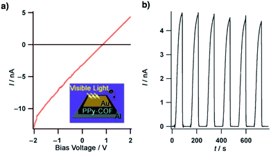 | ||
| Fig. 36 (a) I–V profile of PPy-COF between sandwich-type Al/Au electrodes (black curve: without light irradiation; red curve: upon light irradiation). (b) Photocurrent when the light was turned on or off. Adapted with permission from ref. 268, Copyright 2009 Wiley-VCH. | ||
5.1 p-Type semiconductors
The tetragonal structure in COFs is favourable for high-rate charge carrier transport.305,377C4-Symmetric phthalocyanine and porphyrin derivatives are typical building blocks for the synthesis of semiconducting COFs. Flash photolysis time-resolved microwave conductivity (FP-TRMC) measurements reveal that the nickel(II) phthalocyanine NiPc-COF (Fig. 14c) has a high hole mobility of 1.3 cm2 V−1 s−1, which surpasses those of conventional conjugated polymers.39,378 The eclipsed stacking configuration with a tight layer–layer separation distance of 3.36 Å facilitates hole transport across the out-of-plane direction. NiPc COF absorbs strongly in the ultraviolet and visible regions centred at 680 nm (Q band), achieving a high sensitivity to deep-red and near-infrared photons with a panchromatic response.Metallophthalocyanine MPc-COFs (M = Co(II), Cu(II) and Zn(II)) (Fig. 14c) with a slipped-AA stacking mode facilitate hole transport, while electron transport is negligible, owing to the absence of electron deficient units. Flash-photolysis time-resolved microwave conductivity (FR-TPMC) measurements in Ar and SF6 excited at 355 nm reveal a transient conductivity of 1.4 × 10⁻⁴ cm2 V−1 s−1 for CuPc-COF, 2.2 × 10⁻⁴ cm2 V−1 s−1 for ZnPc-COF and 2.6 × 10⁻⁴ cm2 V−1 s−1 for CoPc-COF. The different mobilities reveal that the metal species significantly affect the carrier transport. It has been revealed that spin-coated MPc-COFs in a sandwich-type gap between Al and Au electrodes are photoconductive and enable quick on–off switching. Indeed, CuPc-COF generates a photocurrent of 110 nA, while CoPc-COF and ZnPc-COF yield a photocurrent of 0.14 and 0.6 nA respectively.113
A series of boronate ester-linked COFs 1-X (X = S, Se and Te) (Fig. 35b) have been synthesised by condensation of HHTP and benzodichalcogenophene diboronic acids. It was found that the conductivity is tunable by changing the chalcogen atoms. The electrical conductivities of 1-S, 1-Se and 1-Te are 3.7 (±0.4) × 10−10, 8.4 (±3.8) × 10−9 and 1.3 (±0.1) × 10−7 S cm−1, respectively, which are higher than those of the corresponding diboronic acid monomers. The higher conductivity of 1-Te originates from the closer interlayer overlap of heavier Te atoms.380
Imine-linked free-base porphyrin COF-366 (Fig. 35c) and COF-66 (Fig. 35d) are hole-transporting materials. Time of flight transient current integration measurements reveal that their one-dimensional hole mobilities are 8.1 and 3.0 cm2 V−1 s−1 for COF-366 and COF-66, respectively.105 Imine-linked SP-3D-COF 1 and SP-3D-COF 2 (Fig. 37a) have been synthesised via the condensation of 3,3′,6,6′-tetraamine-9,9′-spirobifluorene with terephthalaldehyde and biphenyl derivatives, respectively.379 Subsequently, SP-3D-COFs were incorporated into perovskite solar cells. Owing to the long-range conjugated spirobifluorene in the frameworks, SP-3D-COF 1 and SP-3D-COF 2 exhibit enhanced average power conversion efficiencies of 15.9% and 18.0%, respectively (Fig. 37b and d).
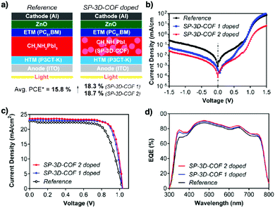 | ||
| Fig. 37 (a) Device architectures. (b) Corresponding dark current density–voltage (J–V) curves. (c) J–V characteristic curves under AM 1.5G 100 mW cm−2 simulated solar light. (d) EQE spectra of the undoped reference and SP-3D-COF-doped PSC devices. Abbreviations: Avg. PCE, average power conversion efficiency; ETM, electron transporting material; HTM, hole transporting material; PC61BM, [6,6]-phenyl-C61 butyric acid methyl ester; ITO, indium–tin oxide; P3CT-K, poly[3-(4-carboxylbutyl)thiophene-K]. Adapted with permission from ref. 379, Copyright 2018 ACS. | ||
The electron-donating tetrathiafulvalene (TTF) unit has been explored for preparing semiconducting 2D and 3D COFs. 2D microporous TTF-Ph-COF (Fig. 26e) and mesoporous TTF-Py-COF (Fig. 35e) show different mobilities.288 TTF-Ph-COF with a shorter interlayer distance of 3.71 Å exhibits a carrier mobility of 0.2 cm2 V−1 s−1, which is 2.5 times higher than that (0.08 cm2 V−1 s−1) of TTF-Py-COF with a larger interlayer separation of 3.87 Å. Doping with iodine achieves a conductivity of 10−5 and 10−6 S cm−1 for TTF-Ph-COF and TTF-Py-COF, respectively. The enhanced conductivity upon iodine doping originates from the generation of charge-transfer complexes between TTF and iodine in the ordered TTF columns. 3D TTF JUC-518 (Fig. 35f) and JUC-519 (Fig. 35g) form charge-transfer complexes with iodine.381 JUC-518 with a non-interpenetrated structure shows a conductivity of 2.7 × 10⁻⁴ S cm−1 at 25 °C, which increases to 1.4 × 10⁻² S cm−1 at 120 °C upon iodine doping after 48 h, which is higher than that (2.9 × 10⁻⁷ S cm−1) of TTF-based MOFs.382–385 The superior conductivity is attributed to the non-interpenetrated crystalline structure, allowing a high surface area of 3018 m2 g−1 for doping.
Among all topologies, the trigonal topology endows COFs with the highest π-column density. HPB-COF (Fig. 21p) and HBC-COF (Fig. 21q) have π-column densities as high as 0.25 and 0.13 nm−2, respectively.48 These densities are much superior to those of supramolecular systems with columnar HPB and HBC π-arrays. FR-TPMC methods reveal that HPB-COF and HBC-COF have a total transient conductivity of 0.8 × 10⁻⁵ and 1.5 × 10⁻⁵ cm2 V−1 s−1, respectively. The hole mobility of HBC-COF is evaluated to be as high as 0.7 cm2 V−1 s−1 (Fig. 38).
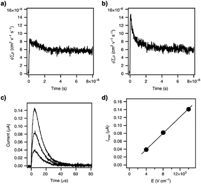 | ||
Fig. 38 (a) Flash photolysis time-resolved microwave conductivity (FP-TRMC) profile of HPB-COF. (b) FP-TRMC profile of HBC-COF. (c) Photocurrent generation of spin-coated HBC-COF on a comb-type gold electrode device (electrode gap = 5 μm) at different bias voltages (2, 4 and 7 V). (d) I–V curve of HBC-COF on the comb-type gold electrode device. (c) I–V curve of a 50 nm-thick CS-COF⊃C60/PMMA film sandwiched between Al and Au electrodes at bias voltages ranging from −1.5 to 1.5![[thin space (1/6-em)]](https://www.rsc.org/images/entities/char_2009.gif) V in air at 25 V in air at 25![[thin space (1/6-em)]](https://www.rsc.org/images/entities/char_2009.gif) °C. (d) Photocurrent switching at a bias voltage of 1.5 °C. (d) Photocurrent switching at a bias voltage of 1.5![[thin space (1/6-em)]](https://www.rsc.org/images/entities/char_2009.gif) V in air at 25 V in air at 25![[thin space (1/6-em)]](https://www.rsc.org/images/entities/char_2009.gif) °C, with repetitive light on–off actions on the 50 nm-thick CS-COF⊃C60/PMMA film. (e) J–V curve of the photovoltaic cell under irradiation with air mass 1.5 conditions (VOC = 0.98 °C, with repetitive light on–off actions on the 50 nm-thick CS-COF⊃C60/PMMA film. (e) J–V curve of the photovoltaic cell under irradiation with air mass 1.5 conditions (VOC = 0.98![[thin space (1/6-em)]](https://www.rsc.org/images/entities/char_2009.gif) V, JSC = 1.7 V, JSC = 1.7![[thin space (1/6-em)]](https://www.rsc.org/images/entities/char_2009.gif) mA mA![[thin space (1/6-em)]](https://www.rsc.org/images/entities/char_2009.gif) cm−2, FF = 0.54). Adapted with permission from ref. 48, Copyright 2015 Springer Nature. cm−2, FF = 0.54). Adapted with permission from ref. 48, Copyright 2015 Springer Nature. | ||
The delocalisation of π clouds over the whole framework is key to charge transport. Phenazine-linked CS-COF (Fig. 15a) with a fully π-conjugated skeleton has been synthesised by condensing triphenylene hexamine with tert-butylpyrene tetranone.304 CS-COF, as revealed by FP-TRMC measurements, is a hole-transporting semiconductor with a remarkable mobility of 4.2 cm2 V−1 s−1. Interestingly, CS-COF presents a hexagonal 1D channel of up to 1.6 nm, which can encapsulate electron-deficient fullerene molecules (25 wt%) to form a bicontinuous donor–acceptor CS-COF⊃C60 system (Fig. 39). Similarly, a phenazine-linked tetragonal phthalocyanine COF (COF-DC-8) (Fig. 15b) exhibits a conductivity of 2.51 × 10⁻³ S m−1 with an activation energy of 324 meV.305 The conductivity increases by 3 orders of magnitude upon doping with iodine, which suggests that COF-DC-8 is a p-type semiconductor. The phenazine-linked ZnPc-pz and CuPc-pz COFs (Fig. 35h)306 achieve hole mobilities of 4.8 (±0.7) cm2 V−1 s−1 and 0.9 (±0.2) cm2 V−1 s−1 at room temperature, respectively, as revealed by Hall effect measurements in the dc limit, with charge carrier densities of 9.1 (±0.3) × 1011 and 2.3 (±0.7) × 1012 cm−3, respectively. The limited mobility of 5 cm2 V−1 s−1 is related to the charge transport between particle boundaries.
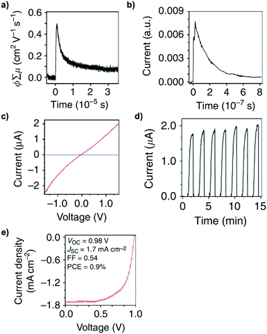 | ||
Fig. 39 (a) Transient conductivities measured using flash photolysis time-resolved microwave conductivity methods on excitation with a 355 nm laser pulse. (b) Time-of-flight transient current integration for CS-COF with a 355 nm laser pulse at a power of 34 mJ cm−2 per pulse. (c) I–V curve of a 50 nm-thick CS-COF⊃C60/PMMA film sandwiched between Al and Au electrodes at bias voltages ranging from −1.5 to 1.5![[thin space (1/6-em)]](https://www.rsc.org/images/entities/char_2009.gif) V in air at 25 V in air at 25![[thin space (1/6-em)]](https://www.rsc.org/images/entities/char_2009.gif) °C. (d) Photocurrent switching at a bias voltage of 1.5 °C. (d) Photocurrent switching at a bias voltage of 1.5![[thin space (1/6-em)]](https://www.rsc.org/images/entities/char_2009.gif) V in air at 25 V in air at 25![[thin space (1/6-em)]](https://www.rsc.org/images/entities/char_2009.gif) °C, with repetitive light on–off actions on the 50 nm-thick CS-COF⊃C60/PMMA film. (e) J–V curve of the photovoltaic cell under irradiation with air mass 1.5 conditions (VOC = 0.98 °C, with repetitive light on–off actions on the 50 nm-thick CS-COF⊃C60/PMMA film. (e) J–V curve of the photovoltaic cell under irradiation with air mass 1.5 conditions (VOC = 0.98![[thin space (1/6-em)]](https://www.rsc.org/images/entities/char_2009.gif) V, JSC = 1.7 V, JSC = 1.7![[thin space (1/6-em)]](https://www.rsc.org/images/entities/char_2009.gif) mA mA![[thin space (1/6-em)]](https://www.rsc.org/images/entities/char_2009.gif) cm−2, FF = 0.54). Adapted with permission from ref. 304, Copyright 2013 Springer Nature. cm−2, FF = 0.54). Adapted with permission from ref. 304, Copyright 2013 Springer Nature. | ||
Boronate-ester linked wavy Marta-COF-1 (Fig. 40d) with a honeycomb lattice exhibits comparable charge transport properties to other conventional 2D COFs.388 The chair-like lattice formation is driven by the steric hindrance of the hydrogens in the peripheral benzene of hexabenzocoronene (HBC). The structural rigidity of HBC at high temperatures up to 130 °C allows retention of the twisted structure in Marta-COF-1 after solvothermal synthesis at 120 °C. Despite its wavy nature, the tight π–π stacking distance between the HBC and pyrene moieties (3.7 Å at the HBC knots, 3.4 Å at the pyrene linker), as observed by HR-TEM, promotes a total transient mobility of 0.6 × 10⁻⁴ cm2 V−1 s−1 in the powdery sample and a mobility of 0.9 × 10⁻⁴ cm2 V−1 s−1 in a 110 nm spin-coated thin film. This reveals the importance of tight interlayer stacking for semiconducting COFs and provides a way to developing COFs with twisted structures.
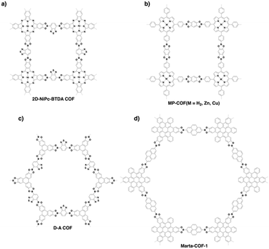 | ||
| Fig. 40 Structures of COFs as (a and b) n-type and (c) ambipolar semiconductors and (d) a 3D wavy COF. | ||
5.2 n-Type semiconductors
Compared to p-type COFs, n-type COFs have not been well explored. Most COFs are p-type semiconductors owing to the fact that most building units are electron rich. Designing COFs to produce n-type semiconductors is possible by employing electron-withdrawing building units. For example, 2D-NiPc-BTBA COF (Fig. 40a) with an electron deficient benzothiadiazole linker is an n-type semiconductor with an electron mobility as high as 0.6 cm2 V−1 s−1 (Fig. 41b and c).386 Notably, 2D-NiPc-BTDA COF is panchromatic (Fig. 41a) and extremely sensitive to near-infrared photons to produce photocurrent, making it an interesting candidate as a photofunctional semiconductor (Fig. 41d–f).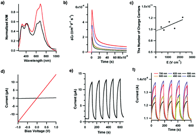 | ||
| Fig. 41 (a) Electronic absorption spectra of 2D-NiPc-BTDA COF (red curve) and [MeO]8PcNi (black curve). (b) Transient conductivities when irradiated with a 355 nm pulsed laser at a photon density of 1.6 × 10¹⁵ under Ar (red curve) and SF6 (blue curve) and after annealing under SF6 for 1 h (orange curve) and 24 h (green curve) or under O2 for 24 h (black curve). (c) Numbers of charge carriers measured by the time-off light transient current integration at different bias voltages, when irradiated with a 355 nm pulsed laser of 5.0 × 10¹⁴ photons cm−2. (d) I–V curves of 2D-NiPc-BTDA COF in the dark (black curve) and upon irradiation (red curve) with visible light. (e) On–off switching of the photocurrent of 2D-NiPc-BTDA COF at a bias voltage of 1.0 V, by switching the light on and off. (f) Wavelength-dependent on–off switching of photocurrent at a bias voltage of 1.0 V. Adapted with permission from ref. 386, Copyright 2011 ACS. | ||
5.3 Ambipolar semiconductors
A porphyrin is a representative macrocycle with 18 π electrons. It is unique as it can coordinate with various metal ions to form metalloporphyrins to achieve a broad diversity of functions. Free base H2P-COF, ZnP-COF and CuP-COF (Fig. 40b) have been investigated to examine the effect of metal species on conductivity.42,387 The AA stacking mode enables the formation of unidirectional porphyrin-on-porphyrin and metal-on-metal columns for charge transport. In particular, H2P-COF exhibits a high hole mobility of 3.5 cm2 V−1 s−1, while CuP-COF favours electron transport to exhibit an electron mobility of 0.19 cm2 V−1 s−1. In contrast, ZnP-COF is an ambipolar conductor with hole and electron carrier mobilities of 0.032 and 0.016 cm2 V−1 s−1, respectively. The high charge mobility stems from the formation of 1D highways of macrocycles and metal ions. In the presence of high electron density porphyrin, H2P-COF favours the transport of holes, while the presence of metal species lowers the electron density of the porphyrin macrocycle, allowing the transport of electrons. Particularly, CuP-COF has the lowest electron density as a result of ligand-to-metal charge transfer from the porphyrin. This eventually gives rise to the good hole mobility observed in CuP-COF.389,390 These porphyrin MP-COFs are photoconductive with high on/off ratios (Fig. 42a and b).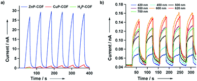 | ||
| Fig. 42 (a) Photocurrents for 2D porphyrin COFs upon repeated switching of the light on and off. (b) Wavelength-dependent on–off switching of the photocurrent of ZnP-COF at a bias voltage of 1.0 V. Adapted with permission from ref. 387, Copyright 2012 Wiley-VCH. | ||
Apart from macrocyclic columns, designing segregated donor and acceptor columns in donor–acceptor COFs can allow ambipolar carrier transport. For example, a donor–acceptor 2D D–A COF (Fig. 40c) condensed from triphenylene and benzothiadiazole is an ambipolar semiconductor with hole and electron mobilities of 0.01 and 0.04 cm2 V−1 s−1, respectively (Fig. 43a and b).263 Moreover, the 2D D–A COF is photoresponsive to generate photocurrent, exhibiting an increase from 0.8 pA to 10.1 nA under irradiation (Fig. 43c and d). In donor–acceptor COFs, the holes and electrons can transport through the independent donor and acceptor π columns, respectively. Using different donor and acceptor units to design donor–acceptor COFs enables the construction of various semiconducting materials that allow ambipolar conduction. How to design ambipolar semiconducting materials with balanced mobilities is still a challenging subject. How the lattice structure and π conjugation affect the charge carrier transport is a key fundamental issue in developing high-performance semiconductors. Disclosing the mechanism of electron and hole transport across the frameworks is a subject of high interest and deserves further investigation.
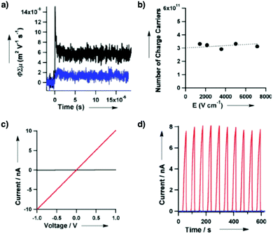 | ||
Fig. 43 (a) FP-TRMC profiles of the 2D D–A COF in Ar (black) and SF6 (blue) atmospheres. (b) Accumulated numbers of photo-induced charge carriers in the 2D D–A COF upon 355 nm pulse exposure. (c) I–V curves of the 2D D–A COF in the dark (black) and upon irradiation (red) with visible light from a Xenon light source. (d) Photocurrents of the 2D D–A COF (red curve), COF-5 (black) and a simple mixture of D and A at a molar ratio of 3![[thin space (1/6-em)]](https://www.rsc.org/images/entities/char_2009.gif) : :![[thin space (1/6-em)]](https://www.rsc.org/images/entities/char_2009.gif) 2 (blue) upon repeated switching of the light on and off. Adapted with permission from ref. 263, Copyright 2012 Wiley-VCH. 2 (blue) upon repeated switching of the light on and off. Adapted with permission from ref. 263, Copyright 2012 Wiley-VCH. | ||
6. Charge separation systems
Assembly of donors and acceptors into segregated bicontinuous structures is a major challenge in increasing the efficiency of charge separation for photovoltaics. Usually, donors and acceptors tend to aggregate to form donor-on-acceptor aggregates, owing to favourable electrostatic interactions. To enable assembly into segregated donor-on-donor and acceptor-on-acceptor structures, conventional approaches typically require the introduction of additional units to trigger other supramolecular interactions that are strong enough to overcome the electrostatic force. Under topology diagrams, we find that polycondensation of donor and acceptor units enables the construction of donor–acceptor COFs without the introduction of any additional units. The donor–acceptor COFs constitute segregated bicontinuous structures so that donor-on-donor and acceptor-on-acceptor π columnar arrays are alternately linked across the material. Compared to other polymer-based donor–acceptor systems, donor–acceptor COFs are unique as they offer a novel and ideal molecular platform for charge separation and collection. The donor–acceptor COF systems have two distinct features. One is that each donor and acceptor are covalently linked in the lattice to form super heterojunctions which facilitate photoinduced electron transfer. Another feature is the donor-on-donor and acceptor-on-acceptor π columns, which facilitate charge separation and offer pathways for carrier transport. These features make donor–acceptor COFs trigger ultrafast electron transfer, rapid and efficient charge separation and charge transport across the independent donor and acceptor π columns. On the other hand, the nanochannels of COFs enable the integration of donor or acceptor guest molecules to constitute donor–acceptor COFs in which the skeletons and pores are set with opposite functions.Donor–acceptor COFs have been explored by condensing zinc phthalocyanine donor knots (DZnPc) with strong electron-accepting naphthalene diimide linkers (ANDI) to constitute tetragonal lattices, where each ZnPc donor is linked with four NDI acceptors, while each NDI unit is connected to two ZnPc donors. The resulting DZnPc–ANDI-COF (Fig. 44a)391 with built-in super heterojunctions enables ultrafast electron transfer from donor to acceptor columns to form charge separated states, as revealed by transient absorption spectroscopy. In this COF, light absorption, electron transfer and charge separation complete within 1.4 ps, indicating an ultrafast electron transfer process. The lifetime of the charge separation state (τcs) is evaluated from the decay of transient cationic radical and anionic radical species, where DZnPc–ANDI-COF in chlorobenzene shows a τcs value of 10 μs. In the solid state, the τcs value evaluated by time-resolved ESR measurements upon laser irradiation (Fig. 45) is 1.8 and 1500 μs at 280 and 80 K, respectively.
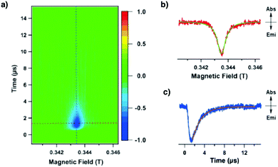 | ||
Fig. 45 (a) Contour plots of the time-resolved ESR spectrum of the solid-state COF at 280 K. The transverse and longitudinal axes denote the time and magnetic field, respectively. The normal axis is the TR-ESR intensity. The negative and positive signs of the signal intensity indicate the absorption and emission of the microwaves, respectively. (b) Time slice of the time-resolved ESR spectrum at t = 1.5 μs. The green line is the line calculated based on the Lorentz function (Abs = absorption and Emi = emission). (c) Time profile of the time-resolved ESR signal under a magnetic field of 0.3435 T. The orange line is the curve calculated based on the exponential function Φ = α![[thin space (1/6-em)]](https://www.rsc.org/images/entities/char_2009.gif) exp[−t/τCS]. Adapted with permission from ref. 391, Copyright 2013 Wiley-VCH. exp[−t/τCS]. Adapted with permission from ref. 391, Copyright 2013 Wiley-VCH. | ||
Inspired by this work, donor–acceptor combinations of ZnPc, CuPc and NiPc with pyromellitic diimide, naphthalene diimide and perylene diimide produce six different donor–acceptor COFs, namely DCuPc–APyrDI-COF, DCuPc–ANDI-COF, DCuPc–APDI-COF, DNiPc–APyrDI-COF, DNiPc–ANDI-COF and DZnPc–APDI-COF (Fig. 44b–g).117 All these donor–acceptor COFs enable efficient charge separation and achieve long lifetimes of over 26 μs. These dynamics enable mechanistic insights into the key photochemical processes involved in optoelectronics and photoenergy conversion systems, which indicate that the donor–acceptor COFs are promising high-performance semiconducting materials for photovoltaics. In these donor–acceptor structures, the metallophthalocyanine donor and diimide acceptor units are interfaced, forming periodically ordered super-heterojunctions. This structure offers an exceptional interface for charge separation, a key issue to be solved in organic and polymeric solar cells. The periodic arrays of donor and acceptor π columns not only provide discrete heterojunctions for photoinduced electron transfer and charge separation, but also offer predesigned pathways for charge transport and collection.117,391 These features and functions make the donor–acceptor COFs establish photovoltaic structures with an ideal mechanism for charge separation and collection in solar cells. Especially, periodic donor-on-donor and acceptor-on-acceptor π arrays play a vital role in enhancing the lifetimes of charge-separated states, as a result of charge carrier migration. These long-lived charge-separation states offer a great opportunity to extract holes and electrons for producing electric current. These features of donor–acceptor COFs and insights into the mechanistic aspects of charge separation constitute the basis for developing COFs for photovoltaic applications.
In addition to the direct use of skeletons for the construction of donor–acceptor COFs, a strategy based on the complementary use of skeletons and pores has been explored to synthesise heterojunctions for charge separation. Electron-donating ZnPc has been developed for the preparation of donor–acceptor [C60]X-ZnPc-COFs by covalently integrating electron accepting C60 into the 1D channels via pore surface engineering (Fig. 46).222 In the absence of C60, ZnPc generates an excited triplet state that eventually undergoes thermal decay. In contrast, [C60]X-ZnPc-COFs form singlet excited states owing to the formation of radical species upon irradiation. As revealed by time resolved ESR measurements, the efficiency of charge separation increases as the content of C60 is increased. Remarkably, the τCS value of [C60]0.3-ZnPc-COF is exceptionally long – 2.66 ms.
A series of donor–acceptor thiophene COFs with different topologies, i.e. kagome 4PE-TT COF (Fig. 47a), kagome 4PE-BDT COF (Fig. 47b) and hexagonal 3PB-BDT COF (Fig. 47c), have been explored to exhibit varying decay time constants, as revealed by time-correlated single photon counting measurements.281 It was noticed that varying the linker length does not significantly alter the decay time constant. Transient absorption measurements reveal that the 4PE-TT film produces a long-lived excited state, up to tens of microseconds. Short-time measurements suggest that all these COFs show fluorescence quenching of singlet excited states, with a recombination time longer than those of conventional polythiophene and polyfluorene conjugated polymers.392,393
TP-Por COF (Fig. 47d) has been synthesised via the reaction of 5,15-bis(4-boronophenyl)-porphyrin with HHTP.394 A thick layer of TP-Por-COF is grown on an ITO substrate, which is further coated with a MoOx layer to fabricate solar cells. The sandwiched ITO/MoOx/TP-Por-COF/ZnO/Al device exhibits a photocurrent density of 44.6 μA cm−2 and an open-circuit voltage of 312 mV under simulated sunlight.
By using isoindigo and thienoisoindigo units as linkers, a series of imine-linked COFs, i.e. Py-pII (Fig. 47e), Py-pTII (Fig. 47f) and Py-tTII COFs (Fig. 47g), have been prepared.395 The optical band gaps of Py-pII, Py-pTII and Py-tTII COFs are 1.78, 1.48 and 1.36 eV, respectively. A Py-tTII COF thin film on an ITO/MoOX electrode with PCBM forms an ordered heterojunction. This donor–acceptor active layer functions as a photodetector that responds to ultraviolet to near infrared light. Interestingly, the device is tuned reversibly from blue and red-sensitive to green and NIR-sensitive by altering the bias voltage to induce almost neat inversion of spectral sensitivity.
Characterisation of exciton dynamics in COFs is difficult due to their strong light scattering character. This can be overcome by preparing stabilised COF-5 (Fig. 14a) colloids with minimal UV/vis light scattering.396 With the colloidal COF-5, transient spectroscopy unravels its excimer excitation. COF-5 exhibits three excited state decay components, which include photoexcited initial excimer formation (4 ps), excimer relaxation (160 ps) and excimer decay (>0.3 ns). The absence of decay in monomeric HHTP emphasises that the cofacial arrangement of HHTP in COF-5 upon crystallisation is the key to exciton diffusion. The exciton diffusion coefficients are estimated to be around 0.02–0.09 cm2 s−1. Interestingly, the size of crystallites affects exciton annihilation. In general, a higher surface area-to-volume ratio leads to a slower annihilation, owing to the fewer surface traps per excitation density and the higher degree of exciton diffusional freedom.
The supramolecular approach allows the noncovalent loading of C60 into the 1D channels of COFs. Subliming C60 into the pores of CS-COF to form CS-COF⊃C60 offers a strategy for charge separation (Fig. 15a).304 CS-COF⊃C60 serves as an active component in solar cells to exhibit a power conversion efficiency of 0.9% and a high open-circuit voltage of 0.98 V (Fig. 48). Similarly, loading the electron acceptor [6,6]-phenyl-C61-butyric acid methyl ester (PCBM) into electron-donating thienothiophene TT-COF (Fig. 44h) yields a host–guest PCBM:TT-COF.264 The confinement of PCBM in the 3 nm channel of TT-COF increases charge transfer efficiency, as a short diffusion pathway allows an efficient extraction of photoinduced charges. Notably, PCBM:TT-COF achieves a fast charge transfer towards PCBM, with a lifetime shortening to below 50 ps (45 and 18 ps) as revealed by photoluminescence spectroscopy. A TT-COF based photovoltaic device demonstrates a power conversion efficiency of 0.053% and a short-circuit current density of 0.213 mA cm−2, with an open-circuit voltage of 0.622 V. An analogue of TT-COF, i.e. BDT-COF (Fig. 35b), has been prepared by using benzodithiophene (BDT) as the linker.397 After modifying the BDT-COF film with [60]PCBM or [70]PCBM, the charge carrier can be transferred from BDT to PCBM efficiently. The film, with a thickness of 80–100 nm, exhibits a hole mobility of 3 × 10⁻⁸ cm2 V−1 s−1.
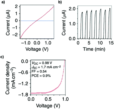 | ||
| Fig. 48 (a) I–V curve of a 50 nm-thick CS-COF⊂C60/PMMA film sandwiched between Al and Au electrodes at bias voltages ranging from −1.5 to 1.5 V in air at 25 °C. (b) Photocurrent switching at a bias voltage of 1.5 V in air at 25 °C, with repetitive light on–off actions on the 50 nm-thick CS-COF⊂C60/PMMA film. (c) J–V curve of the photovoltaic cell under irradiation with air mass 1.5 conditions (VOC = 0.98 V, JSC = 1.7 mA cm−2 and FF = 0.54). Adapted with permission from ref. 304, Copyright 2013 Springer Nature. | ||
COFs offer a general and powerful strategy for designing periodic arrays of donor and acceptor π columns, which are hardly achieved by using other covalent or noncovalent approaches. Therefore, COFs provide an unprecedented molecular platform for constructing donor–acceptor heterojunctions that are ideal for photovoltaics.
7. Spin systems
Utilising electron spin states in electronic devices has attracted great attention owing to its uniqueness in decreasing heat generation. Compared to inorganic analogues, spintronic devices derived from organic semiconductors benefit from cost efficiency, flexibility and low density. However, it is a challenge to explore organic materials to align carbon-based spins into ordered structures.An oxidation strategy has been explored to produce organic radical species in COFs. Semiconducting sp2c-COF (Fig. 15c) upon oxidation with iodine generates polarons in the lattice. ESR spectroscopy reveals that the radicals are organic radicals with a g value of 2.0003, localise on the pyrene knots and do not form bipolarons. The resulting COF upon decreasing the temperature enables spin alignment in one direction via phase transition to form ferromagnetic orderings below 10 K (Fig. 49).308 sp2c-COF is unique as it achieves a high spin density in the framework with nearly 0.71 spin per pyrene unit. Such a high spin density cannot be achieved with 1D conjugated polymers of the same components, amorphous porous materials and imine-linked analogue COFs. The C![[double bond, length as m-dash]](https://www.rsc.org/images/entities/char_e001.gif) C bond linked sp2c-COF offers a platform for exploring organic spin materials with unusual functions.
C bond linked sp2c-COF offers a platform for exploring organic spin materials with unusual functions.
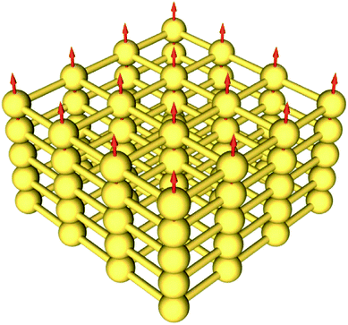 | ||
| Fig. 49 Schematic of spin alignment in sp2c-COF (three-by-three lattice). Red arrows represent spins. The spins are isolated at the knots and are unidirectionally aligned across the framework via ferromagnetic phase transition to develop spin–spin coherence. Adapted with permission from ref. 308, Copyright 2017 AAAS. | ||
A low-crystalline organic radical framework (PTM-CORF) with a polychlorotriphenylmethyl (PTM) knot has been explored (Fig. 50a). The sterically hindered tetrachlorophenyl groups protect the radicals, while its non-planarity prevents the formation of bipolarons. PTM-CORF is stable in air and common solvents and triggers anti-ferromagnetic coupling between neighbouring spins at low temperature.398 Density functional theory (DFT) calculations also revealed that PTM-CORF is anti-ferromagnetic.399
Recently, trioxaazatriangulene TANG-COF (Fig. 50b) has been prepared via imine formation reaction. With a low band gap of 1.18 eV, TANG-COF has an absorption edge of up to 1050 nm. Upon iodine doping, the central nitrogen atoms lose an electron, giving rise to a poly(radical cation) COF. Remarkably, the absorption of the doped TANG-COF extends into the mid-IR region, indicative of a small band gap of 0.2 eV, while its electrical conductivity reaches up to 0.01 S cm−1. Although only 10% free spins are present, doped TANG-COF displays paramagnetic coupling between the unpaired electrons.291
Despite having a small number of magnetic COF systems, the ability of COFs to host ferromagnetism, anti-ferromagnetism and paramagnetism has clearly highlighted the possibilities and demonstrated the potential of COFs to be integrated in spin devices.
8. Smart and sensing systems
Well-ordered skeletons and open 1D nanochannels offer a platform for exploring smart and sensing materials. The skeletons could change their properties, while the pore walls and channels enable the design of various interfaces that control interplays with external stimuli. To date, most studies have focused on the changes in absorption and luminescence properties, while the external stimuli ranged widely from physical stimuli such as mechanical force, light, temperature, and electric and magnetic fields to chemical stimuli such as pH, moisture and chemical compounds (Scheme 6). These properties led to the development of a diversity of different smart and sensing materials. Different from other smart materials, the highly ordered frameworks can be designed to allow cooperation between skeletons and pores so that synergistic effects can be triggered to enhance the responsivity and sensitivity of the materials (refer to Section 2.6 Sensing units).8.1 Photoresponsive smart COFs
We have explored the first example of photo-responsive smart COFs, i.e. Ph-An-COF, by polycondensation of a 2,3,6,7-tetrahydroxyanthracene knot with a 1,3,5-benzenetriboronic acid linker.400 Ph-An-COF (Fig. 51a) exhibits an AA stacking mode to form anthracene columns with an interlayer separation of 3.4 Å. Owing to the short interlayer distance and eclipsed π-stacking mode, a spin-coated Ph-An-COF film with photoresponsive anthracene columns undergoes [2+2] cycloaddition between two anthracene units of adjacent layers to form a cyclic adduct upon irradiation at 360 nm. Heating at 100 °C triggers the reverse reaction to regenerate the anthracene units in Ph-An-COF (Fig. 52a). This process is easily monitored by electronic absorption spectral change to identify isosbestic points. The reversible reactions between the photoinduced cycloaddition and thermally triggered anthracene regeneration induce clear changes in properties. For example, after the formation of cycloaddition dimers in the Ph-An-COF structure, the absorption intensities at 278 nm and 373 nm decreased, while the absorption at 305 nm increased. Detailed examination confirms a linear relationship between photoabsorbance and time, with a rate constant of 4.1 × 10⁻³ min−1 (Fig. 52b–d). The evidence from the spectral changes indicates that Ph-An-COF experiences structural variation from planar 2D sheets to concavo-convex polygon skeletons upon irradiation (Fig. 52b and c).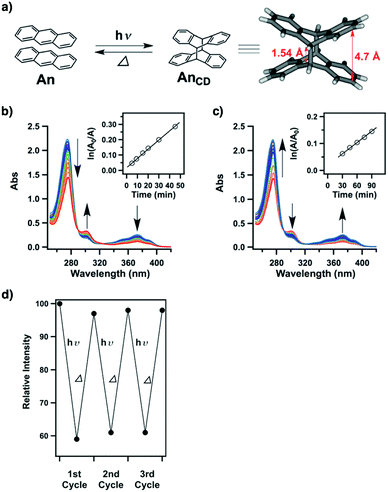 | ||
| Fig. 52 (a) [4π + 4π] anthracene (An) cycloaddition upon irradiation to form the cyclodimer (AnCD) and its thermally allowed reverse reaction (inset: singlet crystal structure of AnCD). (b) Electronic absorption spectral changes of Ph-An-COF upon irradiation at 360 nm (inset: time-dependent profile). (c) Electronic absorption spectral changes of Ph-AnCD-COF upon heating at 100 °C in the dark (inset: time-dependent profile). (d) Cycling performance as revealed by normalised absorbance change. Adapted with permission from ref. 400, Copyright 2015 Wiley-VCH. | ||
Recently, through the [2+2] cycloaddition of vinylene linkages in C![[double bond, length as m-dash]](https://www.rsc.org/images/entities/char_e001.gif) C linked 2D P2PV COF, transformation to cyclobutane-linked 3D P3PcB COF (Fig. 51b) is reported upon halogen lamp irradiation for seven days. The cyclisation reaction leads to an increase in surface area from 880 to 1037 m2 g−1. On the other hand, 2D P2PV COF shows a pore size of 1.1 nm, while after irradiation a new pore centred at 0.65 nm appears. This transformation is reversible after heating at 200 °C for two days. Owing to the breaking of the conjugation, P3PcB COF exhibits significantly decreased fluorescence.260
C linked 2D P2PV COF, transformation to cyclobutane-linked 3D P3PcB COF (Fig. 51b) is reported upon halogen lamp irradiation for seven days. The cyclisation reaction leads to an increase in surface area from 880 to 1037 m2 g−1. On the other hand, 2D P2PV COF shows a pore size of 1.1 nm, while after irradiation a new pore centred at 0.65 nm appears. This transformation is reversible after heating at 200 °C for two days. Owing to the breaking of the conjugation, P3PcB COF exhibits significantly decreased fluorescence.260
Dithienylethenes are a class of well-established photoisomerisation molecules with closed and open forms, in which the open form has limited π conjugation, while the closed isomer enables extended π conjugation, constituting a diversity of photo-responsive smart materials.401 Imine-linked COF-O (Fig. 51c) has been explored with a tris(4-aminophenyl)amine knot and a 1,2-bis(5-formyl-2-methylthien-3-yl)cyclopentene linker. The dithienylethene unit in a COF-O film, synthesised by interfacial polymerisation, adopts an open form with limited π conjugation. Irradiation at 365 nm triggers its photoisomerisation and transforms the open form to a closed cyclohexadiene form to yield COF-C with enhanced π conjugation via C–C bond formation, as suggested by a distinct electronic absorption spectral change (Fig. 53a).402 Irradiation of COF-C with visible light of wavelengths longer than 550 nm causes reversed isomerisation to form COF-O. This photoisomerisation is accompanied by changes in porosity, where COF-O and COF-C were observed to have BET surface areas of 330 and 477 g m−1, respectively. Integrating the COF-O thin film into an electric circuit demonstrates the possibility of a photoswitch, where irradiation of COF-O at 365 nm increases the electrical conductivity from 1 (±0.25) × 10−7 S cm−1 to 2 (±0.23) × 10−5 S cm−1, which is almost a 200-fold increment (Fig. 53b). The switching of electrical conductivity by light originates from photoinduced ring-closing and opening isomerisation reactions. UV light induces photocyclisation in the linker to enhance the π-conjugation and conductivity, while visible light triggers the reverse process to break the π conjugation and to decrease the conductivity.
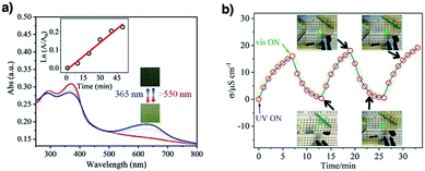 | ||
| Fig. 53 (a) Solid-state absorption spectra of the COF-O film upon irradiation at 365 nm and the COF-C film upon irradiation at >550 nm (inset: time-dependent profile). (b) Changes in the conductivity of COFs illuminated using an LED. Adapted with permission from ref. 402, Copyright 2019 Wiley-VCH. | ||
Owing to the robust backbone and densely packed structure of COFs, it is difficult to achieve any structural variation within the COF backbone. Azobenzene is another isomerisation compound with reversible trans and cis isomers; integrating the azobenzene unit into the COF to yield TTA-AzoDFP COF (Fig. 51d) enables the tuning of its properties.404 TTA-AzoDFP COF undergoes reversible photo-responsive trans–cis isomerisation. The isomerisation of trans azobenzene to its cis isomer significantly affects the morphology, surface wettability and guest adsorption of TTA-AzoDFP COF.
Smart COFs having sensitive crystallinity to solvation have also been reported. For example, a series of imine-linked TAPB-COFs (Fig. 51e) containing alkoxy functionalised building blocks or unsubstituted linear building units with large π-conjugation have been synthesised by condensation of a tris(4-aminophenyl)benzene knot and a variety of dialdehyde linkers.403 TAPB-COFs exhibit reversible switching of their structure from a nonporous and amorphous polymer to a highly crystalline porous framework upon exposure to external solvents, such as acetone, ethanol, toluene, 1,4-dioxane, water and supercritical carbon dioxide (Fig. 54a–c).
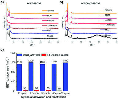 | ||
| Fig. 54 (a) PXRD of BDT TAPB-COF upon solvent treatment and subsequent vacuum drying. (b) PXRD of BDT-OMe TAPB-COF upon solvent treatment and subsequent vacuum drying. (c) Comparison of the calculated BET surface areas of BDT TAPB-COF after scCO2 (re)activation (blue) and 1,4-dioxane vapour treatment (red). Adapted with permission from ref. 403, Copyright 2019 ACS. | ||
8.2 Sensing gases
COFs have been designed as sensors for detecting gases, protons, water molecules, metal ions, explosive chemicals and biomolecules. Generally, π structures including layers, building units and linkages determine the light-emitting functions of COFs. The fluorescence of COFs can be changed upon exposure to external stimuli, such as gases, which provides a chance to fabricate COF-based gas sensors. For example, TAT-COF-2 (Fig. 55a) in the solid state emits at 563 nm upon excitation at 485 nm. This electron deficient COF serves as an acceptor in photoinduced electron transfer from electron rich arenes, enabling the detection of arene vapours.405 The electron transfer greatly enhances the fluorescence intensity in TAT-COF-2 by two-fold. Surprisingly, its fluorescence is recovered in 5 min upon exposure to ambient atmosphere. This enables recycled use of COFs for detecting arene vapours.Highly luminescent TPE-Ph-COF (Fig. 55b) has been explored by using the aggregation-induced emissive TPE unit as the knot to enhance the light-emitting activity of COFs. TPE-Ph-COF exhibits blue luminescence at 500 nm with an absolute fluorescence quantum yield of 32%. Upon exposure to NH3 gas, the luminescence of TPE-Ph-COF decreases sharply, owing to the formation of a Lewis acid–base complex between the open 2pz orbital of the boron atom in the linkage and the lone pair of the nitrogen atom of NH3.55 TPE-Ph-COF can detect NH3 at a sub-ppm level of 4.9 ppm with rapid fluorescence quenching.
Apart from NH3 sensing, formaldehyde detection is also made possible using HHTP-DPB-COF (Fig. 20).406 HHTP-DPB-COF emits at 457 nm upon excitation at 357 nm in DMF. The fluorescence intensity shows rapid quenching upon addition of formaldehyde, a result of the formation of hydrogen-bonding interactions between the HHTP unit in HHTP-DPB-COF and formaldehyde. Detailed studies using density functional theory (DFT) and time-dependent (TD) DFT confirm the presence of a lowest energy hydrogen-bonded COF–formaldehyde complex. It was observed that in HHTP-DPB-COF the electron density of the HOMO is mainly distributed on the HHTP units, while the LUMO is distributed on the 4-ethynylbenzeneboronic acid pinacol ester ligand. In comparison, after the formation of the COF–formaldehyde complex, the LUMO locates on formaldehyde, thus changing the charge transfer process and leading to variation in fluorescence.
A series of COFs for acidic gaseous HCl sensing have been developed. For example, COF-ETBA-DAB (Fig. 55c), synthesised by condensing 4,4′,4′′,4′′′-(ethane-1,1,2,2-tetrayl)benzaldehyde with 1,4-diaminobenzene, exhibits low-intensity and broad luminescence ranging from 520 nm to 680 nm in the solid state. However, after exposure to HCl gas, COF-ETBA-DAB shows an obvious colour change from yellow to red and exhibits an improved emission centred at 670 nm. Its colour and fluorescence intensity are recovered upon exposure to NH3 vapour.217 This phenomenon originates from the reversible protonation and deprotonation processes of the imine linkage triggered by acid and base vapours. Similarly, COF-JLU4 (Fig. 55d) has been designed to utilise its hydrazone linkages to fulfil the protonation and deprotonation processes. It is condensed from 2,5-dimethoxyterephthalohydrazide and triformylphloroglucinol under solvothermal conditions and it emits at 568 nm with a quantum yield of 2.9% in the solid state.219
Owing to its abundant heteroatoms, COF-JLU4 can be well dispersed in water and exhibits variations in fluorescence intensity towards different pH solutions. Its fluorescence increases dramatically at pH = 0.9 but decreases significantly at pH = 13.0. Both fluorescence quenching and enhancement are reversible for up to five cycles without obvious intensity recession.219 COF-HQ (Fig. 55e) and PBHP-TAPT COF (Fig. 24d) respond to gaseous acid vapours or solutions with different pH values, exhibiting changes in fluorescence intensity via protonation and deprotonation processes. In detail, COF-HQ is synthesised through the Schiff-base reaction of 2,5-bis(2-(quinolin-8-yloxy)ethoxy)terephthalaldehyde with 1,3,5-tri-(4-aminophenyl)benzene, and consists of 8-hydroxyquinoline (HQ) side groups. The HQ unit is a pH-sensitive fluorescent group and functions as an accepting site for protons (Fig. 56a). COF-HQ exhibits emission at 682 nm in the solid state upon excitation at 365 nm. The fluorescence intensity of COF-HQ is sensitive to the pH of the solution, showing gradual quenching as the pH value is decreased. The change in fluorescence intensity can be reversed for up to five cycles in the pH range of 1 to 5 (Fig. 56b–d).220
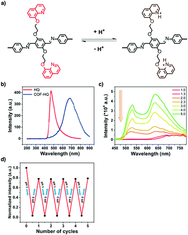 | ||
| Fig. 56 (a) Protonation and deprotonation processes of HQ within the COF-HQ framework in acidic and basic media. (b) Solid-state fluorescence spectra of HQ and COF-HQ. (c) Fluorescence spectra of COF-HQ under various acidic conditions (λex = 365 nm). (d) The repeatability of COF-HQ for five cycles. Adapted with permission from ref. 220, Copyright 2018 ACS. | ||
Different from the above COFs which use side chain or chemical linkages as the accepting sites of protons, PBHP-TAPT COF realises the protonation and deprotonation processes through its triazine backbone. PBHP-TAPT COF is synthesised by the condensation of (1,4-phenylene)bis(3-hydroxyprop-2-en-1-one) and 1,3,5-tris-(4-aminophenyl)triazine and is orange in colour in the solid state. The solid-state photoluminescence spectrum shows that PBHP-TAPT COF exhibits fluorescence at 590 nm upon excitation at 525 nm.
PBHP-TAPT COF shows a rapid response to HCl vapour within seconds by changing its colour from orange to red and it is sensitive to low concentrations of HCl gas, down to 20 ppm.344 The colour variation in PBHP-TAPT COF is switched upon alternate exposure to HCl and NH3 gases. PBHP-TAPT COF retains its structural integrity and sensing ability for five HCl–NH3 exposure cycles, showing its potential for practical application.344
Recently, triazine DHTA-TTA COF has been developed for probing the pH of solutions. DHTA-TTA COF (Fig. 55f) is synthesised by condensing 4,4′,4′-(1,3,5-triazine-2,4,6-triyl)trianiline with 2,5-dihydroxyterephthalaldehyde. It is dispersed on a glassy carbon electrode (GCE) to fabricate an electrochemical sensor so that DHTA-TTA COF serves as a sensor to probe the pH level based on potential signals. This DHTA-TTA COF electrode shows a high sensitivity of 64.2 mV pH−1 in the pH range from 3.0 to 10.0.407
8.3 Sensing humidity
A humidity sensor is an important application in many fields. Water-sensitive COFs have been developed for detecting humidity. Imine-linked DHNDA-TAPP-COF (Fig. 55g) is prepared by condensing 2,4,6-tris(4-aminophenyl)-pyridine with 2,6-dihydroxynaphthalene-1,5-dicarbaldehyde under solvothermal conditions.214 Owing to the reversibility of imine bonds, DHNDA-TAPP-COF transforms from nanoparticles to nanofibers through the dissolution–recrystallisation process. The resulting COF nanofibers show a colorimetric humidity response to colour change, from light yellow in a dry atmosphere (relative humidity (RH), 20%), to light red and dark red when the RH is progressively increased from 20% to 100%. This colour change is repeated many times, enabling facile detection of environmental humidity.Very recently, imine-linked TAPB-PDA-OH COF (Fig. 55h), prepared via condensation of 2,5-dihydroxyterephthalaldehyde and 1,3,5-tris(4-aminophenyl)benzene, has been developed for sensing humidity. TAPB-PDA-OH COF is an orange powder when dry and changes dark upon exposure to water vapour. This change is reversible upon exposure to dry and water-saturated air. The response originates from the tautomerisation of diiminol to an iminol/cis-ketoenamine, as the diiminol structure is more stable in the absence of water. TAPB-PDA-OH COF is sensitive to environmental moisture and exhibits a rapid response to water within 9 s and reverses in less than 1 s when the humid air is changed to dry air.33
TzDa-COF (Fig. 55f) shows two main fluorescence emissions at 500 and 590 nm depending on the water content. Thus, TzDa-COF can act as a ratiometric fluorescent sensor to detect trace water contents in organic solvents (Fig. 57a and b).215 The water sensing is based on an intricate design of the COF skeleton that is equipped with docking sites for interaction with water molecules (Fig. 57c). Recently, a truxene-based COF (COF-TXDBA) (Fig. 55i) that enables humidity sensing has been reported. Condensing 10,15-dihydro-5H-diindeno[1,2-a:10,20-c]fluorene and PDBA yields COF-TXDBA with a high surface area of 1526 m2 g−1.216 In a RH range from 11% to 98%, COF-TXDBA shows a sharp decrease in its impedance by 3 orders of magnitude. Likewise, quick response and recovery times of 37 and 42 s, respectively, were observed in the same RH interval, with a maximum humidity hysteresis error of only about 2.5%. Owing to its stability, COF-TXDBA is recyclable five times.
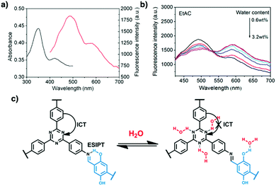 | ||
| Fig. 57 (a) UV-vis absorption (black) and fluorescence (red) spectra of TzDa in pure EtAC. (b) Fluorescence spectra of TzDa in EtAC with different water contents. (c) H2O-sensing mechanism of TzDa. Adapted with permission from ref. 215, Copyright 2017 ACS. | ||
8.4 Sensing metal ions
Heavy metal ions such as Hg2+, Pb2+, Cu2+ and Fe3+ in soils and waters are toxic even at trace levels. Considerable efforts have been made towards exploring methods for effective detection and removal of these ions. Owing to their porous structures and tailored functions, COFs offer ideal materials for sensing and capturing metal ions.COF-JLU3 (Fig. 55j) with salicylaldiminato units on the pore walls offers binding sites to capture Cu2+ ions.93 The fluorescence intensity of COF-JLU3 decreases with increasing Cu2+ ion concentration and the detection limit of Cu2+ ions is 0.31 μM.
COF-LZU8 (Fig. 55k) with thioether-functionalised walls has been explored for the detection and removal of Hg2+ ions. Here, the π-conjugated fluorophore works synergistically with the thioether groups, which serve as Hg2+ receptors.90 COF-LZU8 exhibits fluorescence at 460 nm, which is quenched by adding Hg2+ ions. COF-LZU8 has a low detection limit for Hg2+ ions, at 25 ppb in water.
sp2c-COF (Fig. 15c) in THF exhibits luminescence at 616 nm, which is quenched by adding Cu2+ ions (Fig. 58a–c). The fluorescence quenching is triggered by the photoinduced electron transfer from sp2c-COF to the complex formed between the cyano groups on the pore walls with the Cu2+ ions.309
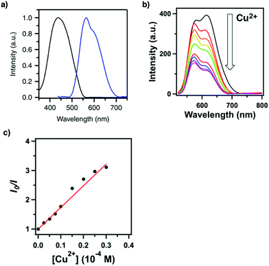 | ||
| Fig. 58 (a) Electronic absorption (black curve) and fluorescence (red curve) spectra of the thin films of sp2c-CON. (b) Fluorescence spectral change of sp2c-COF upon addition of Cu2+ ions. (c) Stern–Volmer plot of the fluorescence quenching by Cu2+ ions. Adapted with permission from ref. 309, Copyright 2018 Springer Nature. | ||
QDCOF (Fig. 55l) emits fluorescence at 440–580 nm upon excitation at 410 nm, which is quenched by UO2+ ions. The quenching originates from the formation of a keto-form structure, where the UO2+ ion coordinates with the N and O atoms of the QDCOF skeleton as revealed by high binding energy shifts of C![[double bond, length as m-dash]](https://www.rsc.org/images/entities/char_e001.gif) N and C
N and C![[double bond, length as m-dash]](https://www.rsc.org/images/entities/char_e001.gif) O by 0.12 and 0.22 eV in XPS.408
O by 0.12 and 0.22 eV in XPS.408
8.5 Sensing anions
COFs show rapid response to anions by enhancing fluorescence intensity. We have explored this possibility with hydrazone-linked COFs to probe F− anions. Condensing 2,5-diethoxyterephthalohydrazide with 1,3,6,8-tetrakis(4-formylphenyl)pyrene yields TFPPy-DETHz-COF (Fig. 55m). TFPPy-DETHz-COF exhibits green-yellow luminescence at 540 nm with a fluorescence quantum yield of 4.5% in THF. Interestingly, its fluorescence is enhanced by 3.8-fold upon addition of F− anions, while the fluorescence quantum yield has been improved to 17%. In contrast, TFPPy-DETHz-COF does not respond to other ions such as Cl−, Br−, I− and NO3−. TFPPy-DETHz-COF enables the detection of F− anions at 4 ppm. The enhancement of fluorescence originates from the deprotonation of hydrazone linkages by F− anions, which suppresses the electron transfer from the linkages to pyrene units.47In comparison with TFPPy-DETHz-COF showing enhanced fluorescence due to F− anions, DATGCl-iCONs (Fig. 55n), which are constructed by condensing triaminoguanidinium chloride with 2,5-dimethoxyterephthalaldehyde, show fluorescence quenching when F− anions are added.409 DATGCl-iCONs dispersed in methanol exhibit blue fluorescence at 441 nm; addition of F− anions triggers proton abstraction that results in significant quenching by 67.3-fold. DATGCl-iCONs exhibit a detection limit of 5 ppb.
Similarly, COF-TT (Fig. 55o) also exhibits fluorescence quenching when anions such as CrO42−, Cr2O72− and MnO4− are added into its solution. COF-TT is condensed from tetra(p-aminophenyl)methane and bis(tetraoxacalix[2]arene[2]triazine) and exhibits luminescence at 490 nm upon excitation at 375 nm in water. Its luminescence is decreased by different anions, where it achieves detection limits of 3.43 × 10⁻⁴ M for CrO42−, 3.43 × 10⁻⁴ M for Cr2O72− and 3.20 × 10⁻⁴ M for MnO4−.
The fluorescence quenching is a diffusion-controlled process and is triggered by competitive light absorption between COF-TT and anions, as the anions absorb more light than COF-TT, resulting in a decreased COF luminescence.410
8.6 Sensing explosives
COFs are promising as sensors for detecting explosives. An azine linked COF (Py-azine COF) (Fig. 14n) has been exploited due to its porosity, crystallinity and stability to detect explosives.202 Py-azine COF exhibits yellow luminescence at 522 nm upon excitation at 470 nm, is sensitive to 2,4,6-trinitrophenol (TNP) and exhibits 69% fluorescence quenching when the concentration of TNP is only 70 ppm in acetonitrile (Fig. 59a and b). This quenching mechanism originates from the photoinduced electron transfer from Py-azine COF to electron deficient TNP, which is facilitated by the formation of hydrogen bonds between the hydroxy unit of TNP and the nitrogen atoms of the azine linker of Py-azine COF.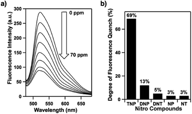 | ||
| Fig. 59 (a) Fluorescence quenching of Py-azine COF upon addition of TNP (0–70 ppm) in acetonitrile. (b) Degrees of fluorescence quenching upon addition of the nitro compounds (70 ppm). Adapted with permission from ref. 202, Copyright 2013 ACS. | ||
TfpBDH-COF (Fig. 60a) has been prepared by condensing 1,3,5-tris(4-formylphenyl)benzene and pyromellitic-N,N′-bisaminoimide. Subsequently, TfpBDH-COF has been exfoliated into TfpBDH-CON to minimise the aggregation of layers. TfpBDH-CON exhibits an emission maximum at 447 nm upon excitation at 365 nm. Its emission is quenched by 63% in the presence of TNP at 5.4 × 10⁻⁵ M.203 This quenching is due to the ground-state charge transfer from the HOMO of TNP− to the LUMO of the protonated TfpBDH-CON. Based on a similar mechanism, PI-CON exfoliated from PI-COF (Fig. 60b)204 exhibits luminescence at 500 nm with a fluorescence quantum yield of 8% in ethanol and its fluorescence intensity shows rapid quenching upon addition of TNP. PI-CON shows a detection limit of 25 μM.
Different from the above COFs which work in organic solvents, imine-linked IMDEA-COF-1 (Fig. 60c) has been exfoliated in water to form a stable water colloid to sense nitrobenzene. IMDEA-COF-1 colloid emits at 510 nm upon excitation at 389 nm and its fluorescence is quenched by 22% upon addition of nitrobenzene at 1.0 × 10⁻³ M.411 The quenching is related to the π–π interaction between nitrobenzene and the surface of IMDEA-COF-1.
Recently, in order to avoid π–π interaction induced fluorescence quenching, a strategy that uses a non-planar pyrene unit to synthesise a luminescent COF has been developed. The resulting Py-TPE-COF (Fig. 60d) emits bright blue light at 462 nm in THF with a 21.1% absolute fluorescence quantum yield in acetonitrile. Py-TPE-COF is sensitive to TNP, with luminescence quenching up to 95.5% in acetone at a TNP concentration of 10 ppm.205 An advanced method is to use 3D building units to impede π–π interaction induced fluorescence quenching.
3D-Py-COF synthesised by condensing tetra(p-aminophenyl)methane with 1,3,6,8-tetrakis(4-formylphenyl)pyrene (Fig. 60e)252 exhibits yellow-green luminescence at 484 nm in DMF. 3D-Py-COF is sensitive to picric acid and shows a quenching degree of 75% at 20 ppm. 1-COF (Fig. 60f) condensed from 1,5-diaminonaphthalene and tri(4-formyl phenoxy)cyanurate emits at 400 nm upon excitation at 320 nm in water and shows fluorescence quenching by 90% upon addition of 1 mM TNP. This quenching originates from the electrostatic interactions and hydrogen-bonding interactions between the hydroxyl group of TNP and the N and O sites of 1-COF. 1-COF is photostable and is recyclable for five cycles.412
In order to improve the π delocalisation, 3BD-COF (Fig. 60g) and 3′PD-COF (Fig. 60h) have been synthesised using the Michael addition-elimination reaction of β-ketoenols with amines (Fig. 61a). In the solid state, the resulting 3BD-COF and 3′PD-COF emit orange light at 547 and 560 nm, respectively. 3BD-COF and 3′PD-COF are sensitive to triacetone triperoxide (TATP), with a detection limit of 1 μM in CH2Cl2 (Fig. 61b and c). The fluorescence quenching is triggered by the oxidation of the enamine unit by TATP.206
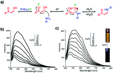 | ||
| Fig. 61 (a) Michael addition–elimination reaction: mechanistic pathway. Photoluminescence spectra of 3′PD (b) and 3BD (c) (λex = 450 nm) dispersions in CH2Cl2 and fluorescence quenching in the presence of TATP (the inset shows the photograph of the 3′PD dispersion, before and after adding TATP). Adapted with permission from ref. 206, Copyright 2017 ACS. | ||
8.7 Sensing biomolecules
The fluorescence properties of COFs are changed by adding biomolecules such as glucose and oligonucleotides. Chiral CCOF-TpTab (Fig. 60i) enables the enantioselective sensing of a wide range of saccharides.241 CCOF-(Λ)-TpTab and CCOF-(Δ)-TpTab emit at 540 nm in pH 7.35 phosphate-buffered saline (PBS) and exhibit varied fluorescence quenching rates upon addition of D-cellobiose. The fluorescence quenching rate of CCOF-(Λ)-TpTab is faster than that of CCOF-(Δ)-TpTab and the association constants are 13![[thin space (1/6-em)]](https://www.rsc.org/images/entities/char_2009.gif) 086 ± 1000 M−1 for CCOF-(Λ)-TpTab and 3806 ± 200 M−1 for CCOF-(Δ)-TpTab. The quenching of fluorescence originates from the formation of a host–guest complex that induces distortion of the COF conformation, as well as excimer formation. Interestingly, CCOF-TpTab is enantioselective towards a wide range of saccharides, showing a fluorescence quenching ratio of 3.62 ± 0.16 for D-maltose and 1.32 ± 0.41 for D-glucuronic acid. This enantioselectivity is triggered by supramolecular interactions between CCOF-TpTab and the saccharides to form different diastereomeric complexes.
086 ± 1000 M−1 for CCOF-(Λ)-TpTab and 3806 ± 200 M−1 for CCOF-(Δ)-TpTab. The quenching of fluorescence originates from the formation of a host–guest complex that induces distortion of the COF conformation, as well as excimer formation. Interestingly, CCOF-TpTab is enantioselective towards a wide range of saccharides, showing a fluorescence quenching ratio of 3.62 ± 0.16 for D-maltose and 1.32 ± 0.41 for D-glucuronic acid. This enantioselectivity is triggered by supramolecular interactions between CCOF-TpTab and the saccharides to form different diastereomeric complexes.
Recently, imine-linked TPA-COF (Fig. 60j) has been synthesised by using two flexible building units, tris(4-aminophenyl)amine and tris(4-formylphenyl)amine, which weaken the interlayer stacking, allowing TPA-COF to be easily exfoliated into ultrathin nanosheets. These nanosheets serve as quenchers to the pre-marked fluorescent hairpin DNA, enabling sensitive and selective detection of targeted DNA. The addition of the nanosheets induces the fluorescence quenching of the DNA solution by 91% in 15 min. The fluorescence quenching originates from the π–π interactions between the nanosheets and the hairpin DNAs. The nanosheets afford a linear detection plot as the concentration of targeted DNA is varied from 0 to 1 nM (Fig. 62a–c).413
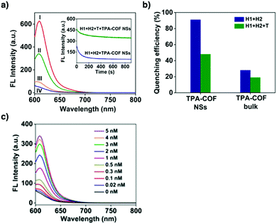 | ||
| Fig. 62 (a) Fluorescence spectra under different conditions: (I) H1 + H2; (II) H1 + H2 + T + TPA-COF NSs; (III) H1 + T + TPA-COF NSs; and (IV) H1 + H2 + TPA-COF NSs. The concentrations of H1, H2, T and TPA-COF NSs in the final solution are 50 nM, 50 nM, 5 nM and 12 μg mL−1, respectively. Inset: Kinetic study on the fluorescence change of H1 + H2 and H1 + H2 + T in the presence of TPA-COF NSs. The excitation and emission wavelengths are 590 and 609 nm, respectively. (b) Fluorescence quenching efficiencies of TPA-COF NSs and bulk TPA-COF. (c) Fluorescence spectra of the proposed sensing platform in the presence of different concentrations. The concentrations of H1, H2 and TPA-COF NSs in the final solution are 50 nM, 50 nM and 12 μg mL−1, respectively. Adapted with permission from ref. 413, Copyright 2017 ACS. | ||
As described above, COFs offer a platform for constructing sensors and smart materials to detect chemicals and to show response to external stimuli. Understanding various interplays for different interfaces in COFs and showing the uniqueness of COFs remain a key fundamental subject in this application. In this sense, we are still at an initial stage to pursue a full use of the structural features of COFs for designing sensing and responsive materials.
9. Energy storage applications
Redox-active small molecules tend to suffer from impaired energy storage performance due to their leakage from electrodes into electrolyte. Covalently linking redox-active moieties into COFs to form networks minimises leakages, thereby opening the possibilities of designing stable cathodes and anodes for energy storage. Owing to the diversity of redox-active units, COFs have been developed for the design of electrodes for supercapacitors and lithium ion, lithium–sulphur and alkaline batteries (Scheme 7). Owing to their different working mechanisms, COFs with different units have been developed for constructing different energy storage devices (refer to Section 2.4 Redox active units).9.1 Supercapacitors
Redox-active moieties are key to the high capacitance of pseudocapacitors, based on the redox reactions of COFs. Various redox active moieties such as anthraquinone and pyridine have been investigated to construct COFs for pseudocapacitors. Hexagonal DAAQ-TFP COF (Fig. 63a) with an anthraquinone linker facilitates reversible charge storage with a capacitance of 48 ± 10 F g−1 at a current density of 0.1 A g−1 in 1 M H2SO4 electrolyte (Fig. 64a and b).121 However, this capacitance is much lower than the theoretical value of 311 F g−1, corresponding to 2.5% accessibility of the anthraquinone sites. By preparing an oriented DAAQ-TFP COF film on a gold substrate, the anthraquinone accessibility is increased to 80% to reach an areal capacitance of 3 mF cm−2 (Fig. 64c and d).122 This result indicates that reducing the contact resistance between COFs and electrodes can facilitate the delivery of electrons to the redox sites. Imine-linked hexagonal TaPa-Py COF (Fig. 63b) bearing a pyridine linker as the redox active centre achieves a high capacitance of 209 F g−1 at a current density of 0.5 A g−1 in 1 M H2SO4 electrolyte.120 The high capacitance originates from the pseudocapacitance of the redox-active TaPa knot, i.e. the faradaic contribution of the pyridine linker. This is proven by the presence of two peaks in the cyclic voltammogram (CV). A control DAB-TFP COF without pyridine has a significantly lower capacitance of 31 F g−1 at 200 mV s−1 than TaPa-Py COF (139.4 F g−1). The synergistic effect of the faradaic contribution and the high surface area of 687 m2 g−1 leads to its improved performance. At a current density of 5 A g−1, it exhibits a capacitance of 164 F g−1. These results suggest that redox active anthraquinone and TaPa units are essential for COFs to be fabricated into pseudocapacitors.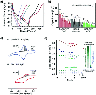 | ||
| Fig. 64 (a) Representative galvanostatic charge–discharge responses for DAAQ-TFP COF (red), monomer 1 (black), DAB-TFP COF (green), monomer 2 (purple) and a carbon black-only electrode (blue) at a current density of 0.1 A g−1. (b) Plots of the average capacitances (of 3 electrodes, error bars = ±1 std. dev.) of each electrode type at different applied current densities. (c) Cyclic voltammograms (50 mV s−1) of a DAAQ-TFP COF slurry-modified electrode (blue) and a DAAQ-TFP thin film (180 nm) (red) in 1.0 M H2SO4. The integrated charge of the oxidative wave and the percentage of quinones accessed are listed for each cyclic voltammogram. (d) Thin-film capacitances derived from GCDC experiments at a current density of 150 μA cm−2. A DAAQTFP COF slurry-modified electrode (teal) and a blank Au electrode (gray) show low capacitance values. Oriented thin films each show improved capacitance as a function of thickness: 250 nm (red), 98 nm (blue) and 62 nm (green). Adapted with permission from ref. 121 and 122, Copyright 2013 and 2015 ACS. | ||
Nitrogen rich triphenylamine TPPDA-TPPyr COF (Fig. 63c) and TPPDA-TPTPE COF (Fig. 63d) have been designed for pseudocapacitors.414 The nitrogen rich units in the COFs enable a reversible redox reaction, yielding an electrochemical double-layer capacitance. Remarkably, the capacitance reaches 237.1 F g−1 for TPPDA-TPTPE COF and 188.7 F g−1 for TPPDA-TPPyr COF at a current density of 2 A g−1 in 1 M KOH. TPPDA-TPTPE has a higher capacitance, owing to its higher surface area of 1067 m2 g−1 and pore volume of 0.84 cm3 g−1. Nevertheless, both exhibit moderate stability, with 86.2% and 85.6% capacitance retention, respectively, after 5000 cycles at a high current density of 10 A g−1.
Intramolecular hydrogen-bonding interaction is important for high capacitance retention. Two phenolic COFs with hydroxyl groups on the pore walls, i.e. TpPa-(OH)2 (Fig. 63e) and TpBD-(OH)2 (Fig. 63f), show higher capacitance than non-functionalised TpPa-1 and TpBD and methoxy functionalised TpPa-(OMe)2 and (TpBD-(OMe)2).123 CV measurements show that TpPa-(OH)2 achieves a capacitance of 396 F g−1 at a scan rate of 2 mV s−1. Control experiments with the non-functionalised TpPa-1 and the methoxy counterpart TpPa-(OMe)2 reveal that their specific capacitances at a scan rate of 2 mV s−1 are only 6 and 13 F g−1, respectively. These comparative results suggest the importance of tautomerisation to form ketoenamine units which contribute to pseudocapacitance. Notably, TpPa-(OH)2 retains 66% of its capacitance after 10![[thin space (1/6-em)]](https://www.rsc.org/images/entities/char_2009.gif) 000 cycles. The capacitance retention originates from the protected carbonyl group of the benzoquinone unit via hydrogen-bonding interactions with the neighbouring amine groups in TpPa-(OH)2. Similarly, another phenolic TpBD-(OH)2 COF exhibits a specific capacitance of 86 F g−1 at a scan rate of 2 mV s−1, while TpBD and TpBD-(OMe)2 without hydroxyl groups in the backbone exhibit capacitances of only 29 and 16 F g−1, respectively.
000 cycles. The capacitance retention originates from the protected carbonyl group of the benzoquinone unit via hydrogen-bonding interactions with the neighbouring amine groups in TpPa-(OH)2. Similarly, another phenolic TpBD-(OH)2 COF exhibits a specific capacitance of 86 F g−1 at a scan rate of 2 mV s−1, while TpBD and TpBD-(OMe)2 without hydroxyl groups in the backbone exhibit capacitances of only 29 and 16 F g−1, respectively.
Benzobisthiazole linked PG-BBT (Fig. 63g) that is capable of intramolecular hydrogen-bonding interactions reaches a capacitance of 729 F g−1 at a scan rate of 5 mV s−1.415 The capacitance is retained up to 96% at a current density of 1 A g−1 after 10![[thin space (1/6-em)]](https://www.rsc.org/images/entities/char_2009.gif) 000 cycles. The discharge capacitances of PG-BBT are 724, 619, 566, 496 and 412 F g−1 at current densities of 1, 2, 3, 5 and 10 A g−1, respectively, as revealed by CV measurements. The high capacitance originates from the synergistic effects of the redox-active benzobisthiazole unit and hydrogen bonding interactions that facilitate proton-coupled electron transfer. The benzobisthiazole unit allows for the reversible radical charge kinetics, while the presence of nitrogen sites enhances the wettability of the COF electrode. As a control, BZ-BBT COF (Fig. 63g) without hydroxyl groups shows a capacitance of 166 F g−1 at a current density of 1 A g−1.
000 cycles. The discharge capacitances of PG-BBT are 724, 619, 566, 496 and 412 F g−1 at current densities of 1, 2, 3, 5 and 10 A g−1, respectively, as revealed by CV measurements. The high capacitance originates from the synergistic effects of the redox-active benzobisthiazole unit and hydrogen bonding interactions that facilitate proton-coupled electron transfer. The benzobisthiazole unit allows for the reversible radical charge kinetics, while the presence of nitrogen sites enhances the wettability of the COF electrode. As a control, BZ-BBT COF (Fig. 63g) without hydroxyl groups shows a capacitance of 166 F g−1 at a current density of 1 A g−1.
Preparing thin films of COFs to use as electrodes simplifies device fabrication. An imine-linked TpOMe-DAQ COF film (Fig. 63h) is prepared by the mechanochemical grinding method. The resulting film exhibits a BET surface area of 1734 m2 g−1 and a pore size of 2.3 nm and it is stable under acidic (12 M HCl, 18 M H2SO4) and basic conditions (9 M NaOH).124 This film achieves a capacitance of 1600 mF cm−2 (169 F g−1) at a current density of 3.3 mA cm−2 in 3 M H2SO4 electrolyte. In contrast, an anthraquinone Dq1Da1Tp COF film (Fig. 63i) prepared by the same grinding method exhibits improved flexibility and mechanical strength when integrated with an electron rich anthracene unit.416 One distinct feature is that the thickness of the free-standing electrode can be controlled between 25 and 100 μm and the area can be extended to 15 cm2 by controlling the amount of COF precursor paste. Dq1Da1Tp COF shows a capacitance of 111 F g−1 at a current density of 1.56 mA cm−2.
In addition to direct co-condensation to prepare redox active COFs, pore surface engineering has been explored to introduce redox-active species into COFs. The typical organic radical TEMPO is covalently linked onto the pore walls of electrochemically inert NiP-COF.125 This method successfully produces two radical COFs, i.e. [TEMPO]50%-NiP-COF (Fig. 31c) and [TEMPO]100%-NiP-COF (Fig. 31c) with different contents of TEMPO units on the pore walls. [TEMPO]50%-NiP-COF and [TEMPO]100%-NiP-COF exhibit capacitances of 124 F g−1 and 167 F g−1, respectively, at a current density of 100 mA g−1. [TEMPO]100%-NiP-COF, owing to its higher TEMPO content, has a higher capacitance than [TEMPO]50%-NiP-COF. At a relatively high current density of 2000 mA g−1, [TEMPO]100%-NiP-COF exhibits a capacitance of 113 F g−1 (Fig. 65a and b). Immobilizing the TEMPO units into the pores of the COFs can mitigate the dissolution of TEMPO units during the charge–discharge process, so that their recyclability is enhanced. This is evident in [TEMPO]50%-NiP-COF, which retains its capacitance without any loss after 100 cycles (Fig. 65c). Narrow peak separations of 155 and 186 mV between the cathodic and anodic peaks for [TEMPO]50%-NiP-COF and [TEMPO]100%-NiP-COF (Fig. 65d), respectively, demonstrate that these COFs enable fast ion transport across the pores. [TEMPO]50%-NiP-COF has a small peak separation as it has a higher surface area of 264 m2 g−1 and a larger pore size of 1.6 nm compared to those (5.2 m2 g−1 and 1.4 nm) of [TEMPO]100%-NiP-COF. This study offers a way to designing pseudocapacitors by pore surface engineering, via anchoring of redox-active units onto the pore walls.
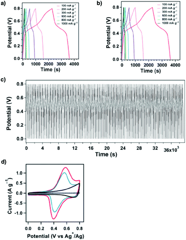 | ||
| Fig. 65 Charge and discharge curves of (a) [TEMPO]100%-NiP-COF and (b) [TEMPO]50%-NiP-COF at different current densities. (c) Charge and discharge stability of [TEMPO]50%-NiP-COF over 100 cycles at a current density of 500 mA g−1. (d) CV profiles of [TEMPO]100%-NiP-COF (red curve), [TEMPO]50%-NiP-COF (blue curve), [Ph]100%-NiP-COF (black curve) and a mixture of carbon black and PTFE (dotted curve), in the form of film electrodes. Adapted with permission from ref. 125, Copyright 2015 Wiley-VCH. | ||
COFs usually exhibit low intrinsic electrical conductivity, which limits their capacitance. This issue is addressed by increasing their intrinsic conductivity. For example, coordinating nickel(II) ions into salphen COFs to form conductive Ni-COF (Fig. 63j) enhances the electrical conductivity to 1.3 × 10⁻² and 1.2 S cm−1 for powder and thin film forms, respectively.417 The synergistic effects of the conjugated skeleton, ordered pores and dense redox units enable a high specific capacitance of 1257 F g−1 at 1 A g−1, with 94% capacitance retention after 10![[thin space (1/6-em)]](https://www.rsc.org/images/entities/char_2009.gif) 000 cycles. An asymmetric capacitor is prepared by using activated carbon as the negative electrode and Ni-COF as the positive electrode; it delivers a capacitance of 417 F g−1 at a current density of 1 A g−1 to achieve an energy density of 130 W h kg−1 and a power density of 839 W kg−1. Knoevenagel condensation yields C
000 cycles. An asymmetric capacitor is prepared by using activated carbon as the negative electrode and Ni-COF as the positive electrode; it delivers a capacitance of 417 F g−1 at a current density of 1 A g−1 to achieve an energy density of 130 W h kg−1 and a power density of 839 W kg−1. Knoevenagel condensation yields C![[double bond, length as m-dash]](https://www.rsc.org/images/entities/char_e001.gif) C bond linked g-C34N6-COF (Fig. 63k) which affords a flexible thin film electrode for fabricating microsupercapacitors (MSCs).418 As revealed by CV measurements, the specific areal capacitances reach 15.2, 9.4 and 5.1 mF cm−2 at scan rates of 2, 100 and 500 mV s−1, respectively (Fig. 66a and b). The galvanostatic charge–discharge curves show nearly triangular shapes and confirm the capacitive behaviour of COF-MSC. The capacitance retains up to 45% when the current density is increased from 0.05 to 5 mA cm−2 (Fig. 66c). COF-MSC is stable enough to achieve 93.1% capacitance retention even after 5000 charge–discharge cycles.
C bond linked g-C34N6-COF (Fig. 63k) which affords a flexible thin film electrode for fabricating microsupercapacitors (MSCs).418 As revealed by CV measurements, the specific areal capacitances reach 15.2, 9.4 and 5.1 mF cm−2 at scan rates of 2, 100 and 500 mV s−1, respectively (Fig. 66a and b). The galvanostatic charge–discharge curves show nearly triangular shapes and confirm the capacitive behaviour of COF-MSC. The capacitance retains up to 45% when the current density is increased from 0.05 to 5 mA cm−2 (Fig. 66c). COF-MSC is stable enough to achieve 93.1% capacitance retention even after 5000 charge–discharge cycles.
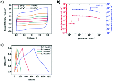 | ||
| Fig. 66 (a) CV curves at scan rates from 2 to 20 mV s−1. (b) The specific areal (CA) and volumetric capacitances (CV) at different scan rates. (c) GCD curves at current densities from 0.05 to 0.4 mA cm−2. Adapted with permission from ref. 418, Copyright 2019 Wiley-VCH. | ||
e-JUC-510, e-JUC-511 and e-JUC-512 (Fig. 63l) nanosheets have been investigated for supercapacitive properties.419 The 22 nm-thick nanosheets of e-JUC-510, e-JUC-511 and e-JUC-512 reach capacitances of 4.17, 5.46 and 5.85 mF cm−2 at 1000 mV s−1, respectively. A power density of 5.32 and 4.08 W cm−1 is achieved with e-JUC-511 and e-JUC-512, respectively.
Preparing COF composites by mixing with conducting polymers, graphene and nickel nanowires improves their electrical conductivity. Inserting conductive poly(3,4-ethylenedioxythiophene) (PEDOT) into the pores of DAAQ-TFP COF (Fig. 63a) forms a PEDOT@DAAQ-TFP-COF composite.420 This electrode exhibits an electrical conductivity of 1.1 S cm−1, a high specific capacitance of 1663 F g−1 at a current density of 1 A g−1, ultrafast charge–discharge rate performance, with a capacitance of 998 F g−1 at 500 A g−1 and excellent stability after 10![[thin space (1/6-em)]](https://www.rsc.org/images/entities/char_2009.gif) 000 cycles. A TpPa-COF@PANI/polyaniline (PANI) (Fig. 63e) composite exhibits a specific capacitance of 95 F g−1 at a current density of 0.2 A g−1 and shows 83% capacity retention after 30
000 cycles. A TpPa-COF@PANI/polyaniline (PANI) (Fig. 63e) composite exhibits a specific capacitance of 95 F g−1 at a current density of 0.2 A g−1 and shows 83% capacity retention after 30![[thin space (1/6-em)]](https://www.rsc.org/images/entities/char_2009.gif) 000 cycles.421 Nanocoating of TpPa-COF (Fig. 63e) on nickel nanowires (NiNWs) yields a metal–COF composite, NiNWs@TpPa-COFs.422 This hybrid material shows a capacitance of 426 F g−1 at a current density of 2 A g−1 and retains a capacitance of 314 F g−1 at a current density of 50 A g−1. An in situ growth of COFDAAQ-BTA on 3D graphene (Fig. 63m) enables the preparation of a composite thin film, which achieves a capacitance of 31.7 mF cm−2.419 The capacitance stems from an enhanced conductivity as well as increased accessibility of redox-active sites when the films are deposited on graphene.
000 cycles.421 Nanocoating of TpPa-COF (Fig. 63e) on nickel nanowires (NiNWs) yields a metal–COF composite, NiNWs@TpPa-COFs.422 This hybrid material shows a capacitance of 426 F g−1 at a current density of 2 A g−1 and retains a capacitance of 314 F g−1 at a current density of 50 A g−1. An in situ growth of COFDAAQ-BTA on 3D graphene (Fig. 63m) enables the preparation of a composite thin film, which achieves a capacitance of 31.7 mF cm−2.419 The capacitance stems from an enhanced conductivity as well as increased accessibility of redox-active sites when the films are deposited on graphene.
These key strategies and progress unambiguously demonstrate that COFs are unique in designing electrodes for pseudocapacitive energy storage. Skeletons, side walls and pores can be developed for integrating redox-active units in the preparation of COF electrodes. These approaches provide a way to tailored interfaces so that redox reactions and capacitive energy storage are mediated in one framework. How to increase the conductivity, density and accessibility of redox-active sites and optimal pore size and shape is a key issue to be solved to fabricate COFs that combine power density, energy density and rate performance.
9.2 Lithium ion batteries
The ordered pores enable lithium ion storage and make COFs function as lithium ion batteries when coupled with redox-active skeletons. Redox-active naphthalenediimide (NDINA) units have been interwoven into DTP–ANDI-COF (Fig. 67a) that functions as a cathode for lithium ion batteries.324 The carbonyl groups of NDINA serve as the redox active species for the reversible lithiation and delithiation processes (Fig. 68a). DTP–ANDI-COF exhibits a superior performance to the NDINA cathode, as DTP–ANDI-COF successfully resolves the dissolution issue. At a current density of 200 mA g−1 (equivalent to 2.4C), the initial capacity of NDINA is only 7.9 mA g−1, corresponding to 10% accessibility of the imide groups, which is five times lower than that (42 mA g−1) of DTP–ANDI-COF. After 50 cycles, the capacity of NDINA decreases to 4.1 mA h g−1, while DTP–ANDI-COF retains its capacity up to 21 mA h g−1. The better performance of DTP–ANDI-COF is attributed to its high porosity of 1583 m2 g−1, as well as its ordered mesoporous channel of 5.06 nm and large pore volume of 0.78 cm3 g−1, which facilitate Li+ ion diffusion. The capacity is enhanced by in situ growth of DTP–ANDI-COF on carbon nanotube (CNT) wires to produce a DTP–ANDI-COF@CNT composite. CNTs increase its conductivity to achieve a capacity of 67 mA h g−1 at a current density of 200 mA g−1 while retaining 100% coulombic efficiency over 100 cycles (Fig. 68b and c).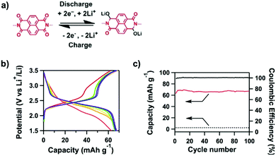 | ||
| Fig. 68 (a) Electrochemical redox reaction of a naphthalene diimide unit. (b) Discharge–charge curves of DTP–ANDI-COF@CNTs upon 100 cycles at a rate of 2.4C (red, 1st cycle; orange, 10th cycle; yellow, 20th cycle; green, 50th cycle; blue, 80th cycle; and purple, 100th cycle). (c) Capacities of DTP–ANDI-COF@CNTs (red line) and CNT (dotted black line) batteries and coulombic efficiencies of DTP–ANDI-COF@CNTs for 100 cycles (black line). Adapted with permission from ref. 324, Copyright 2015 Springer Nature. | ||
Carbazole Cz-COF1 (Fig. 67b) is redox active and shows a capacity of 628 mA h g−1 at a current density of 100 mA g−1, which is much better than that of the amorphous counterpart Cz-CMP1 (313 mA h g−1).119 This difference suggests that an ordered structure is crucial for facilitating lithium ion transport and increasing capacity. At a current density of 200 mA g−1, Cz-COF1 exhibits long-term cycling stability. For instance, Cz-COF1 retains a capacity of 236 mA h g−1, while the coulombic efficiency is 99% even after 400 cycles. These results demonstrate the key roles of the ordered structures and 1D channels of COFs in battery applications.
Microporous PIBN COF (1.5 nm) (Fig. 67c) with abundant carbonyl groups has been prepared by reacting tetramino-benzoquinone (TABQ) with pyromellitic dianhydride (PMDA) in dimethyl sulphoxide (DMSO) at 180 °C.420 Subsequently, a PIBN–G composite has been prepared by growing PIBN COF on graphene. The abundant carbonyl groups in PIBN COF and the PIBN–G composite account for 10 Li+ ions binding per unit to achieve a high charge capacity (Fig. 69a). The PIBN–G composite exhibits a capacity of 244.7 mA h g−1 at a current density of 0.1C, corresponding to 86.1% utilisation efficiency of all carbonyl units (Fig. 69b). The capacity stems from the ordered 1D channels with 1.5 nm width that facilitate the transport of electrolytes, with sizes ranging from 0.38 to 0.72 nm (1,3-dioxolane, dimethoxyethane and lithium bis(trifluoromethanesulphonyl)imide (LiTFSI)). The discharge capacity of the PIBN–G composite is as high as 271.0 mA h g−1 (601 W h kg−1), which is close to the theoretical capacity of 280.0 mA h g−1 (Fig. 69c). The enhanced performance of the composite originates from the facilitated ion transfer and improved conductivity.
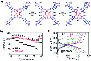 | ||
| Fig. 69 (a) Schematic gradual lithiation and delithiation of the different kinds of carbonyl groups of PIBN in discharge and charge cycles. (b) Rate performances of PIBN–G and PIBN and (c) discharge/charge profiles. The current and capacity are based on the mass of PIBN. Adapted with permission from ref. 420, Copyright 2018 Wiley-VCH. | ||
β-Ketoenamine-linked Tp-DANT-COF (Fig. 67d) and imine-linked Tb-DANT-COF (Fig. 67e) with naphthalenediimide units serve as cathodes.421 Tp-DANT COF and Tb-DANT COF have improved cycling performances compared to monomeric 2,7-bis((E)-benzylideneamino)benzo[lmn][3,8]phenanthroline-1,3,6,8(2H,7H)-tetraone (DANTB). For instance, at a high current density of 7.5C, the Tp-DANT COF cathode is able to deliver an initial capacity of 72.8 mA h g−1 and a stable capacity of 71.7 mA h g−1 after 600 cycles. On the other hand, Tb-DANT COF retains a capacity of 80.1 mA h g−1 after 300 cycles at 3.4C, while DANTB experiences a decrease of capacity to 75 mA h g−1 only after 10 cycles. The improved cycling stability suggests that the COFs prevent the degradation of redox active units.
N2-COF (Fig. 67f) and N3-COF (Fig. 67g) with pyrimidine and triazine knots exhibit high initial capacities of 737 (discharge) and 731 mA h g−1 (charge) and of 689 (discharge) and 707 mA h g−1 (charge), respectively, at a current density of 1 A g−1. The energy storage is based on the two-electron redox reaction in the pyrimidine unit of N2-COF and the three-electron reaction in the triazine moiety of N3-COF, respectively.422 N2-COF and N3-COF also retain 82% and 81% of the initial capacities after 500 cycles, respectively.
Phenazine-linked DAPH-TFP COF (Fig. 67h) exceeds the performance of conventional anthraquinone-based lithium ion batteries.342 For instance, neat DAPH-TFP delivers a capacity of 81.7 mA h g−1, while DAAQ-TFP is 53.5 mA h g−1 at 0.5C. Incorporation of PEDOT further enhances the capacity to 93.2 mA h g−1 for PEDOT@DAPH-TFP. This originates from the improved conductivity in PEDOT@DAPH-TFP as evidenced by electrochemical impedance spectroscopy. PEDOT@DAPH-TFP retains unity coulombic efficiency after 500 cycles.
Mechanochemical grinding has been developed for preparing PA-COF (Fig. 67i) and TB-COF (Fig. 67j) with pyrimidine knots.423 PA-COF and TB-COF exhibit discharge capacities of 321.9 and 311.4 mA h g−1 and charge capacities of 267.0 and 262.4 mA h g−1, respectively, for the first cycle at a low current density of 0.1 A g−1. Their coulombic efficiencies are 82.94 and 84.25%, respectively, after 3 cycles. Interestingly, PA-COF and TB-COF exhibit a gradual increase in capacity to 401.3 and 379.1 mA h g−1, respectively, after 500 cycles, while the coulombic efficiency is increased to 99%. The improved capacity and efficiency originate from the gradual activation of the redox-active skeleton during the repeated charge–discharge processes.424,425 At a current density of 1 A g−1, PA-COF and TB-COF exhibit capacities of 240.0 and 226.2 mA h g−1, with capacity retentions of up to 74.8% and 72.7%, respectively, after 500 cycles.
Exfoliating COFs into CONs or growing COF sheets on conducting substrates enables the exploration of 2D organic sheets in energy storage. In CONs, the decreased layer number improves the accessibility of the redox-active sites, which is crucial to high-rate performance. In this case, a quick transport of electrons and ions becomes possible. DAAQ-TFP-COF (Fig. 63a) is exfoliated into 5 nm thick DAAQ-ECOF sheets via ball milling.426 The capacity of the DAAQ-ECOF sheets is doubled to reach 107 mA h g−1 at a current density of 500 mA g−1 and is tripled to yield 76 mA h g−1 at 3000 mA g−1 compared to that of pristine DAAQ-TFP-COF. Remarkably, DAAQ-ECOF exhibits a capacity of 107 mA h g−1 with 98% retention after 1800 cycles at a current density of 500 mA g−1. Similarly, exfoliated DABQ-ECOF (Fig. 67k) with redox-active pyrene tetraone sites and TEMPO-ECOF (Fig. 67l) with redox-active TEMPO units have been developed for lithium ion batteries. DABQ-ECOF and TEMPO-ECOF exhibit capacities of 210 and 110 mA h g−1, which are 35% and 53% enhancements, respectively, compared to those of the bulk DABQ-COF and TEMPO-COF at a current density of 20 mA g−1. Exfoliated TFPB-COF (Fig. 67m) with a rich benzene backbone exhibits an initial capacity of 1369 mA h g−1, which decreases to 968 mA h g−1 after 300 cycles. This is much superior to that (126 mA h g−1) of bulk TFPB-COF after 300 cycles.427 Interestingly, IISERP-CON1 (Fig. 67n) with a 1,3,4-triazole linker is self-exfoliated during the reaction, owing to its flexible triazole unit, enabling the direct preparation of anodes.428 It exhibits a capacity of 720 mA h g−1 at a current density of 100 mA g−1. This is attributed to the hydroxyl groups and nitrogen sites which enable reversible binding of Li+ ions.
Usually, the imine C![[double bond, length as m-dash]](https://www.rsc.org/images/entities/char_e001.gif) N bond and phenyl unit hardly serve as redox-active moieties. Growing a 5 nm thick COF-LZU1 sheet (Fig. 67o) onto carbon nanotubes (CNTs) forms a COF@CNT composite, which achieves a capacity of 1536 mA h g−1 at a current density of 100 mA g−1 (Fig. 70a).326 In contrast, bulk pristine COF-LZU1 powder shows a capacity of only 125 mA h g−1 (Fig. 70b). Density functional theory (DFT) calculations reveal that a 14-electron process is involved in energy storage (Fig. 70c). All the C
N bond and phenyl unit hardly serve as redox-active moieties. Growing a 5 nm thick COF-LZU1 sheet (Fig. 67o) onto carbon nanotubes (CNTs) forms a COF@CNT composite, which achieves a capacity of 1536 mA h g−1 at a current density of 100 mA g−1 (Fig. 70a).326 In contrast, bulk pristine COF-LZU1 powder shows a capacity of only 125 mA h g−1 (Fig. 70b). Density functional theory (DFT) calculations reveal that a 14-electron process is involved in energy storage (Fig. 70c). All the C![[double bond, length as m-dash]](https://www.rsc.org/images/entities/char_e001.gif) N linkages and aromatic C
N linkages and aromatic C![[double bond, length as m-dash]](https://www.rsc.org/images/entities/char_e001.gif) C bonds of COF-LZU1@CNT induce redox reaction and contribute to the reversible binding of Li+ ions. However, other studies on imine-linked COFs@CNTs did not show this phenomenon. The COF@CNT anode exhibits a gradual activation process. Initially, the anode has discharge and charge capacities of 928 and 383 mA h g−1, respectively, with a coulombic efficiency of 41.3%. The discharge and charge capacities increase to 1032 and 1021 mA h g−1, respectively, owing to layer expansion during the charge–discharge process after 500 cycles.
C bonds of COF-LZU1@CNT induce redox reaction and contribute to the reversible binding of Li+ ions. However, other studies on imine-linked COFs@CNTs did not show this phenomenon. The COF@CNT anode exhibits a gradual activation process. Initially, the anode has discharge and charge capacities of 928 and 383 mA h g−1, respectively, with a coulombic efficiency of 41.3%. The discharge and charge capacities increase to 1032 and 1021 mA h g−1, respectively, owing to layer expansion during the charge–discharge process after 500 cycles.
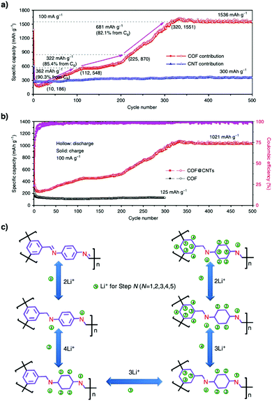 | ||
| Fig. 70 (a) Capacity contribution of the COF (based on the mass of the COF) in COF@CNTs at 100 mA g−1. (b) Cycling performances of the COF and COF@CNTs at 100 mA g−1. (c) Reversible five-step lithium-ion insertion and extraction reactions with a COF monomer. Adapted with permission from ref. 326, Copyright 2018 Springer Nature. | ||
Fully π-conjugated 2D CCP-HATN (Fig. 67p) with a hexaazatriphenylene knot and a C![[double bond, length as m-dash]](https://www.rsc.org/images/entities/char_e001.gif) C linkage shows a capacity of 62.5 mA h g−1.429 This capacity is levelled by directly growing a 2.8 nm-thick 2D CCP-HATN sheet (surface area = 317 cm2 g−1, pore sizes = 0.68 and 1.28 nm, theoretically 0.8 and 1.6 nm) on CNTs to form a 2D CCP-HATN@CNT hybrid. In contrast to the result of COF-LZU1@CNT, the resulting composite shows a capacity of only 116 mA h g−1, in which the contribution of CNTs is 31 mA h g−1. Growing CONs or nanosheets on CNTs is a general approach to increase the accessibility of the redox active sites as well as conductivity, so that the capacity and rate performance are improved simultaneously.
C linkage shows a capacity of 62.5 mA h g−1.429 This capacity is levelled by directly growing a 2.8 nm-thick 2D CCP-HATN sheet (surface area = 317 cm2 g−1, pore sizes = 0.68 and 1.28 nm, theoretically 0.8 and 1.6 nm) on CNTs to form a 2D CCP-HATN@CNT hybrid. In contrast to the result of COF-LZU1@CNT, the resulting composite shows a capacity of only 116 mA h g−1, in which the contribution of CNTs is 31 mA h g−1. Growing CONs or nanosheets on CNTs is a general approach to increase the accessibility of the redox active sites as well as conductivity, so that the capacity and rate performance are improved simultaneously.
9.3 Lithium sulphur batteries
The lithium–sulphur battery (LSB) is an emerging energy storage device, owing to its high theoretical capacity as well as sulphur abundancy. However, the current status of research is still seeking a solution to the shuttle effect, i.e. the dissolution of polysulphide intermediates into electrolyte, which seriously impairs its cycling performance. Nevertheless, COFs offer a different platform for challenging this hurdle. As COFs are designable, they serve as hosts to confine sulphur, while their backbones can form covalent bonds with sulphur or polysulphides to prevent the dissolution and shuttle effect.Confining sulphur into crystalline porous triazine frameworks has been reported to generate cathodes for LSBs. As a proof of concept, a high temperature melt-diffusion method at 155 °C loads 34 wt% sulphur into microporous CTF-1 (Fig. 14m).430 The resulting CTF-1/S@155 °C composite delivers a discharge–charge capacity of 1497 and 1304 mA h g−1, respectively, in the first cycle at a current density of 0.1C. The low potential hysteresis of 0.2 V between the discharge and charge processes indicates the fast transition kinetics of lithium polysulphides and lithium sulphides in the pores of CTF-1. This is attributed to the improved electrical contact between the embedded sulphur and CTF-1 wall. The discharge capacity of CTF-1/S@155 °C decreases to 762 mA h g−1 after 50 cycles at a current density of 0.1C. In contrast, the CTF-1/S@RT composite prepared at room temperature delivers a lower initial capacity of 1015 mA h g−1 and decreases to 480 mA h g−1 after 20 cycles. This low performance results from the poor inclusion of sulphur in CTF-1 at low temperature, which greatly impairs the performance as intermediates can easily diffuse out into the electrolyte. This comparison illustrates that successful embedment of sulphur in pores is key to their performance.
Large porosity plays a key role in the physical loading of sulphur into COFs. For example, Por-COF/S and Py-COF/S with sulphur loading contents of 55 and 70 wt%, respectively, have been synthesised.431,432 Por-COF (Fig. 35c) has a pore volume of 0.71 cm3 g−1 and Por-COF/S exhibits an initial discharge capacity of 1166 mA h g−1 at 0.5C. The discharge capacity decreases to 929 mA h g−1 in the second cycle and then gradually decreases to 633 mA h g−1 after 200 cycles, which is 0.16% per cycle decay at 0.5C. This decrease is probably related to the residual sulphur on the outer surface of Por-COF. Py-COF (Fig. 26a) shows a high pore volume of 1.25 cm3 g−1 and 70 wt% sulphur is loaded into the pores by the melt-diffusion method. Py-COF/S exhibits a high initial discharge capacity of 1064 mA h g−1 at 1C and achieves a capacity as high as 963.4 mA h g−1 after 100 cycles.
Inducing electrostatic interactions between lithium polysulphides (Li2Sx) and the pore walls of COFs stabilises the Li2Sx species and reduces the shuttle effect. For example, loading sulphur into COF-1 (Fig. 14d) to form COF-1/S433 induces interactions between positively polarised Bδ+ atoms and negatively polarised Oδ− atoms of the linkages in COF-1 with Sx2− and Li+, respectively, which mitigate the shuttle effect. The resulting composite exhibits an initial capacity of 1628 mA h g−1 while retaining 95% coulombic efficiency over 100 cycles at a current density of 0.2C (Fig. 72). This performance originates from interactions with pore walls which trap lithium polysulphides in the COF pores.
One-pot in situ sulphur immobilisation offers a facile approach to covalently link sulphur in CTFs. Fluorine decorated FCTF-S (Fig. 71a) with a 50 wt% sulphur loading content has been developed by heating the perfluorinated aromatic nitrile monomer with sulphur at 160 °C initially and then 400 °C.434 This temperature-programming method melts sulphur at 160 °C, promotes the ring-opening polymerisation of S8 and subsequently facilitates the trimerisation of nitrile to generate FCTF-S at 400 °C. X-ray photoelectron spectroscopy (XPS) proves the existence of C–S bonds. Moreover, the polar semi-ionic C–F bonds in FCTF-S induce a positively charged framework that can trap the negatively charged polysulphides via electrostatic interactions. These features enable sulphur confinement in FCTF-S to achieve an initial capacity of 1296 mA h g−1 at 0.1C and a capacity of 833 mA h g−1 after 150 cycles at 0.5C.
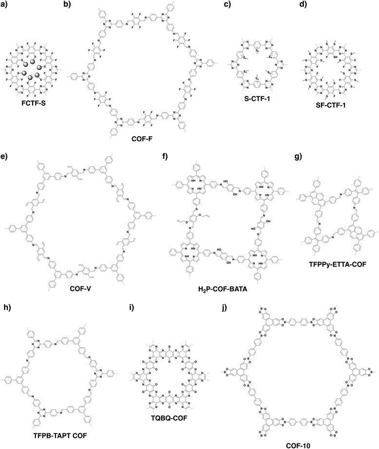 | ||
| Fig. 71 Structures of COFs designed for (a–g) lithium–sulphur batteries, (h and i) sodium ion batteries and (j) potassium ion batteries. | ||
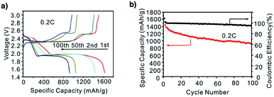 | ||
| Fig. 72 (a) Electrochemical performance of the COF-1/S composite cathode: discharge/charge voltage profiles at 0.2C. (b) Capacity retention when cycled at 0.2C for 100 cycles. Adapted with permission from ref. 433, Copyright 2016 Wiley-VCH. | ||
A fluoro-substituted COF (COF-F) (Fig. 71b) forms covalent bonds with sulphur and loads 61 wt% sulphur.435 This composite exhibits an initial discharge capacity of 1120 mA h g−1 at 0.1C and shows a decay rate of 0.04% per cycle over 100 cycles, indicating that covalent bonds prevent the shuttling of lithium polysulphide intermediates. S-CTF-1 (Fig. 71c),436 SF-CTF-1 (Fig. 71d)437 and S-COF-V (Fig. 71e)226 have been explored. S-CTF-1 is prepared similarly to FCTF-S via high temperature sulphur melting and ring opening polymerisation of S8 for covalent sulphur immobilisation. It achieves an initial capacity of 670 mA h g−1 at 0.05C and cycling performance with 85.8% retentivity after 300 cycles. Stepwise temperature-programming synthesis at 160 °C and then 400 °C promotes trimerisation of nitrile groups to form F-CTF, which upon covalent bonding of sulphur chains to the triazine backbone yields SF-CTF-1 (Fig. 73a). It achieves a capacity of 1138.2 mA h g−1 at 0.05C with a retentivity of 81.6% at 1C after 300 cycles (Fig. 73b and c).
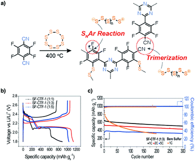 | ||
Fig. 73 (a) Synthetic scheme for the synthesis of SF-CTF-1s involving elemental sulphur-mediated nitrile trimerisation along with the simultaneous covalent attachment of elemental sulphur via SNAr chemistry. (b) The first discharge–charge curves of SF-CTF-1s measured at 0.05C in the voltage range of 1.8–2.7 V. (c) Cycling performance and coulombic efficiencies of SF-CTF-1 (1![[thin space (1/6-em)]](https://www.rsc.org/images/entities/char_2009.gif) : :![[thin space (1/6-em)]](https://www.rsc.org/images/entities/char_2009.gif) 3) at 1C, 2C and 5C over 300 cycles (1C = 1000 mA g−1). Adapted with permission from ref. 437, Copyright 2017 Wiley-VCH. 3) at 1C, 2C and 5C over 300 cycles (1C = 1000 mA g−1). Adapted with permission from ref. 437, Copyright 2017 Wiley-VCH. | ||
The vinyl-functionalised mesoporous COF (Fig. 71e, COF-V) reacts with elemental sulphur at 200 °C to form S-COF-V, which achieves an initial capacity of 1324 mA h g−1 and a capacity of 959 mA h g−1 after 100 cycles at a current density of 0.2C.226 Appending vinylene groups to the pore walls of H2P-COF-BATA (Fig. 71f) enables the post-synthetic grafting of polysulphides via radical copolymerisation reaction.438 The resulting S@H2P-COF-BATA reaches a stable discharge capacity of 1100 mA h g−1 after exhaustive step-wise charge–discharge assessment from 0.1C to 0.5C, which is superior to that (810 mA h g−1) of non-vinyl S@H2P-COF.
A novel strategy for covalently immobilising polysulphide chains into an imine-linked framework, i.e. TFPPy-ETTA-COF (Fig. 71g), has been developed to prevent the shuttle effect of polysulphides.439 By heating sulphur with TFPPy-ETTA-COF at 300 °C, the C![[double bond, length as m-dash]](https://www.rsc.org/images/entities/char_e001.gif) N imine units in TFPPy-ETTA-COF trigger the ring-opening polymerisation of cyclic S8 to form polysulphide chains and anchor them onto the pore walls via C–S bonds. This covalent immobilisation transforms inert TFPPy-ETTA-COF into redox-active polysulphide@TFPPy-ETTA-COF with a 64 wt% polysulphide loading content. The resulting polysulphide@TFPPy-ETTA-COF exhibits an almost unchanged capacity after 60 cycles as well as retains up to 54% of the initial capacity (1069 mA h g−1) after 130 cycles (Fig. 74). A slow capacity decay suggests that covalent immobilisation is critical to performance.
N imine units in TFPPy-ETTA-COF trigger the ring-opening polymerisation of cyclic S8 to form polysulphide chains and anchor them onto the pore walls via C–S bonds. This covalent immobilisation transforms inert TFPPy-ETTA-COF into redox-active polysulphide@TFPPy-ETTA-COF with a 64 wt% polysulphide loading content. The resulting polysulphide@TFPPy-ETTA-COF exhibits an almost unchanged capacity after 60 cycles as well as retains up to 54% of the initial capacity (1069 mA h g−1) after 130 cycles (Fig. 74). A slow capacity decay suggests that covalent immobilisation is critical to performance.
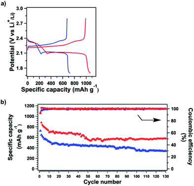 | ||
| Fig. 74 (a) Charge–discharge profiles of polysulphide@TFPPy–ETTA–COF (red) and S@TFPPy–ETTA–COF (blue) at 0.1C. (b) Cycling performances and coulombic efficiencies of polysulphide@TFPPy–ETTA–COF (red) and S@TFPPy–ETTA–COF (blue) over 100 cycles at 0.1C. Adapted with permission from ref. 439, Copyright 2019 RSC. | ||
For the immobilisation of elemental sulphur or polysulphides, COF-F (Fig. 71b) undergoes nucleophilic substitution with SeS2, forming COF-F-SeS2.440 The high conductivity of COF-F-SeS2 enhances its capacity. Remarkably, COF-F-SeS2 delivers a discharge capacity of 1633 and 1163 mA h g−1 at 0.1C and 1C, respectively. COF-F-SeS2 exhibits a cycling performance of 59% retention after 100 cycles.
The current strategies to confine sulphur or polysulphides have witnessed a great achievement from simple physical loading, to strong interactions and to covalent immobilisation in designing COFs for lithium sulphur batteries. Although this is still in its infancy, designing COFs to enhance sulphur content and to improve cycling stability is an important direction worthy of further investigation.
9.4 Sodium ion batteries
COF films with different thicknesses have been prepared as rechargeable anodes for sodium ion batteries.441 By adopting the ball-milling method, DAAQ-TFP COF (Fig. 63a) films with thicknesses of 100–250 nm can be prepared in 30 min. Dissolving these thin films in methane sulphonic acid followed by reprecipitation with methanol yields films with thicknesses of 4–12 nm. These films serve as anodes for sodium ion batteries and achieve capacities of 500 and 450 mA h g−1 at current densities of 50 mA g−1 and 75 mA g−1, respectively. Remarkably, their capacity retention is up to 99% even after 10![[thin space (1/6-em)]](https://www.rsc.org/images/entities/char_2009.gif) 000 cycles, demonstrating their promising cycling stability (Fig. 75). The excellent performance originates from their thin film structure, which balances the reactivity and stability of the radical intermediates, leading to cycling durability.
000 cycles, demonstrating their promising cycling stability (Fig. 75). The excellent performance originates from their thin film structure, which balances the reactivity and stability of the radical intermediates, leading to cycling durability.
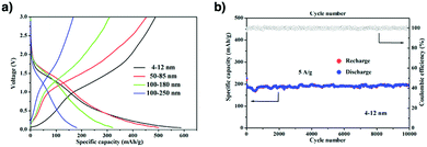 | ||
| Fig. 75 (a) Electrochemical performance of the samples with different thicknesses: (a) voltage profiles plotted for the second cycles of the samples with different thicknesses at a current density of 50 mA g−1. (b) Cycling performance of the 4–12 nm thick sample at a current density of 5000 mA g−1. Adapted with permission from ref. 441, Copyright 2019 ACS. | ||
Imine-linked TFPB-TAPT COF (Fig. 71h) could serve as an anode material for sodium ion batteries, delivering an initial reversible capacity of 246 mA h g−1 and retaining a capacity of 125 mA h g−1 after 500 cycles at a current density of 30 mA g−1.442 In this case, the nitrogen atoms in the imine linkages and triazine knots bind to Na+ ions, as confirmed by N–Na bond formation in XPS, with a Na1s peak at 1071 eV. Therefore, designing COFs with abundant heteroatoms that are redox active and enable interactions with Na+ ions offer a way to constructing electrodes for sodium ion batteries.
TQBQ-COF (Fig. 71i) with triquinoxalinylene and benzoquinone units achieves a high reversible capacity of 452.0 mA h g−1 and maintains 352.3 mA h g−1 after 100 cycles at 0.02 A g−1.443 DFT calculations reveal that 12 Na+ ions are stored per TQBQ-COF unit owing to the pyrazine and carbonyl sites. This is in agreement with the fact that the C![[double bond, length as m-dash]](https://www.rsc.org/images/entities/char_e001.gif) O, C–O and C–N peak intensities vary in the sodiated and desodiated samples as revealed by XPS. A pouch cell consisting of a Na anode, a TQBQ-COF cathode and NaPF6-DEGDME electrolyte is assembled to achieve a capacity of 54.4 mA h g−1 after 20 cycles at a current of 50 mA. This hints at a practical application of COFs in future pouch cell set-ups.
O, C–O and C–N peak intensities vary in the sodiated and desodiated samples as revealed by XPS. A pouch cell consisting of a Na anode, a TQBQ-COF cathode and NaPF6-DEGDME electrolyte is assembled to achieve a capacity of 54.4 mA h g−1 after 20 cycles at a current of 50 mA. This hints at a practical application of COFs in future pouch cell set-ups.
9.5 Potassium ion batteries
A few layers of boronate ester-linked COF-10 with a thickness of 6 nm (Fig. 71j) are grown onto CNTs to fabricate an anode for potassium ion batteries.444 The resulting COF-10@CNT has an initial charge capacity of 348 mA h g−1 (Fig. 76a), which is much superior to that of COF-10 itself (130 mA h g−1). The reversible capacity of COF-10@CNT reaches 288 mA h g−1 after 500 cycles at a current density of 0.1 A g−1, with a contribution from the CNTs of 24.6 mA h g−1 (Fig. 76b). The K+ ion storage is driven by π-cation interactions between K+ ions and the π clouds of the triphenylene knot and biphenyl linker of COF-10. After the first cycle, the interlayer spacing is found to increase from 0.35 to 0.41 nm, owing to the intercalation of K+ ions between layers.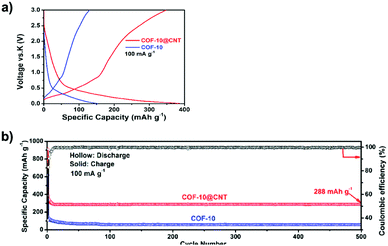 | ||
| Fig. 76 (a) The first charge and second discharge profiles of COF-10@CNT and COF-10. (b) Cycling performance of COF-10@CNT and COF-10 at a current density of 100 mA g−1. Adapted with permission from ref. 444, Copyright 2019 ACS. | ||
Merging conductivity, redox activity, ion transport and stability in one material is an ultimate goal in designing electrodes for energy storage. In this sense, COFs offer a unique platform as their skeletons, pores and wall interfaces are fully designable; integrating desired units into one COF to construct tailor-made interfaces for promoting conduction, redox reaction and ion motion is highly possible. This is a future direction that deserves further efforts.
10. Adsorption and separation
Porous materials have been widely and intensively explored for adsorption and separation as their high pore volumes can offer spaces large enough to accommodate molecules, while their pore sizes, shapes and walls enable the discrimination of guests. Among various frameworks, COFs are unique as they are fully designable in terms of both their skeletons and pores to create tailor-made interfaces for controlling their interactions with specific targets (refer to Section 2.2 Adsorption units). This structural designability enables the development of various COFs for tackling adsorption and separation and offers a chemical basis for a wide scope of targets as different molecules and ions require different interactions (Scheme 8). Progress over the past 15 years in interfacial design has showcased a diversity of COFs to challenge this goal.10.1 Gas adsorption
Hydrogen adsorption is interesting as H2 has a high-volume energy density as a fuel. Adsorption of H2 requires small pores to confine H2 molecules, while an effective approach to increasing interactions between porous materials and H2 is quite limited. Most porous materials for H2 adsorption are used at extremely low temperature at 77 K or under high pressure. This is because there are no specific interactions involved between porous materials and H2.Early examples of COFs have been developed for targeting H2 adsorption. Table 1 summarises the capacities for hydrogen adsorption by COF-1, COF-5, COF-6, COF-8, COF-10, COF-102, COF-103, COF-18 Å and TDCOF-5.11 Among them, COF-102 and COF-103 achieve high capacities of 72.4 and 70.5 mg g−1, respectively. Unfortunately, all these results are obtained at a low temperature of 77 K. A cobalt-based phthalocyanine COF (CoPc-BPDA COF) shows a hydrogen uptake of 1.2 wt% at 77 K and 1 bar (Fig. 77a).445
Ammonia is a Lewis base and a corrosive gas. Reversible storage is a must for its transportation and industrial use. Boroxine or boronate ester-linked COFs are efficient for NH3 adsorption, owing to their high content of boron atoms with open 2pz orbitals, which triggers Lewis acid–base interactions with NH3 to attain a high adsorption capacity.446 COF-10 (Fig. 71j) with 3.4 nm sized mesopores and a surface area of 1200 m2 g−1 shows an uptake capacity of 15 mol kg−1, which is superior to those of commercial adsorbents.
COF-10 is regenerated after heating at 200 °C under 0.1 Torr for 12 h, while its adsorption capacity after three cycles decreases by 4.5%. However, the pore size distribution of COF-10 spreads by 1–3 nm after three cycle. As the NH3 molecule has a size (2.56 Å) that is smaller than the interlayer separation (3.64 Å) of COF-10, NH3 is supposed to enter between layers to form a sandwich structure. Therefore, NH3 molecules are trapped between the Lewis acidic surfaces of the boronate ester rings of two neighbouring layers.446
Stable imine-linked 2D ILCOF-1 (Fig. 77b), owing to the presence of pyrene units that enhance interlayer π–π stacking and increase the crystallinity and porosity, exhibits a high BET surface area of 2723 m2 g−1, a pore size of 2.3 nm and a pore volume of 1.21 cm3 g−1 (at P/P0 = 0.96). At 40 bar, ILCOF-1 exhibits a capacity of 47 mg g−1 for H2 at 77 K and 179 mg g−1 for CH4 at 298 K. From the isotherm curves, it is clear that the H2 adsorption is saturated above a pressure of 35 bar, while more CH4 can be trapped even above 40 bar. The U.S. Department of Energy (DOE) requires H2 and CH4 storage capacities of 4.5 wt%447 at −40 to 85 °C and 5–12 bar and 50 wt% at −40 to 85 °C and 1–12 bar, respectively.448 For CH4 uptake, none of the COFs has reached the DOE target. In order to improve the H2 uptake of COFs by enhancing metal–hydrogen orbital interactions, integrating transition metals into COFs has been tested. However, this approach sacrifices gravimetric adsorption capacity, owing to the heavy weight of metal species. Designing COFs to have high surface areas and small pores and to improve interactions is critical to room temperature H2 and CH4 adsorption. This direction is worthy of investigation.
Elaborate design of COFs has advanced CO2 uptake and separation with the aim of achieving high capacity and selectivity. CO2 is a gaseous molecule without dipolar moment but with a large quadrupole moment. Boronate- and boroxine-linked COFs have limited interactions with CO2 and their CO2 uptake capacity is determined by their pore size and pore volume. For example, COF-1, COF-5, COF-6, COF-8, COF-10, COF-102 and COF-103 exhibit a pore-size determined CO2 adsorption at 273 K. In this series, COF-6 (Fig. 21c) with the smallest pore size of 0.9 nm exhibits the highest CO2 capacity of 166 mg g−1 at 273 K and 760 Torr.78 Due to the specific 3D structure of triptycene, TDCOF-5 (Fig. 77c) with a triptycene knot exhibits a high surface area of 3832 m2 g−1. In TDCOF-5, the space-enlarging triptycene knot renders the aromatic planes parallel to the pore channels. This structure enables more boron sites to be exposed to CO2. As a result, TDCOF-5 with a pore size of 2.6 nm exhibits an uptake capacity of 92 mg g−1 at 273 K and 1 bar, with a Qst value of 21.8 kJ mol−1, while COF-5 (2.7 nm) shows a capacity of only 58.7 mg g−1 under the same conditions.319
For CO2 uptake, we have explored two strategies for designing COFs, i.e. skeleton design and pore surface engineering to show their effectiveness in enhancing their interactions with CO2. To find the principle behind CO2-adsorbing COFs, we have developed microporous hexagonal COFs with different knots but similar pore sizes and volumes. Four hexagonal COFs, i.e. TFPB–TAPB–COF, TFPA–TAPB–COF, BTMA–TAPA–COF and TFPA–TAPA–COF, with different triarylamine contents have been developed. The triarylamine knot that can interact with CO2 due to its weak basicity and the triphenyl benzene knot that negligibly interacts with CO2 are selected for the construction of imine-linked COFs. Interestingly, despite their weak point-to-point interaction, COFs with a high density of these weakly interactive sites induce a remarkable collective effect. Indeed, in this series, TFPA-TAPA-COF (Fig. 21g) shows the highest capacity to achieve CO2 uptakes of 52 and 105 mg g−1 at 298 and 273 K, respectively, and exhibits a Qst value of 28.4 kJ mol−1.23 These results indicate that introducing basicity into COFs is effective in adsorbing CO2. One key finding is that COFs can amplify the insignificant individual effect into collective results. This discloses a general strategy for designing COFs to achieve CO2 uptake and separation.
Using different nitrogen-containing units including triphenylamine (TPA), triphenylpyridine (TPP) and triphenyltriazine (TPT)449 enables the design of a series of amine, pyridine and triazine knotted hexagonal COFs for CO2 uptake. The TPA, TPP and TPT knots enable the synthesis of a series of hexagonal COFs via the [C3 + C3] topology diagram. The pore sizes range from 1.80 to 2.01 nm for TPA-COFs and 2.13 to 2.55 nm for TPT-COFs. TPA-TPA-COF (Fig. 77d), TPA-TPP-COF (Fig. 77e) and TPA-TPT-COF (Fig. 77f) exhibit CO2 uptake capacities of 68.68, 82.42 and 91.15 mg g−1 at 273 K and 1 bar (Fig. 78), with Qst values of 16.05, 25.88 and 28.11 kJ mol−1, respectively. On the other hand, TPT-TPA-COF (Fig. 77g), TPT-TPP-COF (Fig. 79a), and TPT-TPT-COF (Fig. 79b) show CO2 adsorption capacities of 54.03, 59.44 and 92.38 mg g−1 at 273 K and 1 bar (Fig. 78h), with Qst values of 9.70, 16.97 and 30.59 kJ mol−1, respectively. Clearly, the nitrogen content in the COFs is a main factor in controlling the CO2 uptake. As the nitrogen atoms in pyridine units (TPP) are electronegative, they endow the skeleton with polarised positive and negative charges which enhance interactions with CO2. As a result, the TPP COF is more accessible to CO2 than the TPA COF.
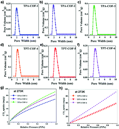 | ||
| Fig. 78 Pore size distribution profiles of the TPA-COFs: (a) TPA–TPA-COF (TPA-COF-1), (b) TPA–TPP-COF (TPA-COF-2), (c) TPA–TPT-COF (TPA-COF-3) and (d) TPT–TPA-COF (TPT-COF-4), (e) TPT–TPP-COF (TPT-COF-5) and (f) TPT–TPT-COF (TPT-COF-6). (g) CO2 uptake profiles of the TPA-COFs at 273 K and 1 bar: TPA–TPA-COF (TPA-COF-1), TPA–TPP-COF (TPA-COF-2) and TPA–TPT-COF (TPA-COF-3). (h) CO2 uptake profiles of the TPT-COFs at 273 K and 1 bar: TPT–TPA-COF (TPT-COF-4), TPT–TPP-COF (TPT-COF-5) and TPT–TPT-COF (TPT-COF-6). Adapted with permission from ref. 449, Copyright 2014 RSC. | ||
Besides knot structures, linkages also play a role in CO2 uptake. A typical example is the azine linkage which has two N atoms in one unit and is efficient in CO2 uptake. ACOF-1 (Fig. 79c) is constructed by condensing hydrazine with 1,3,5-triformylbenzene under solvothermal conditions. The short N![[double bond, length as m-dash]](https://www.rsc.org/images/entities/char_e001.gif) N linkage allows the construction of hexagonal ACOF-1 with a small pore size of 0.94 nm. Indeed, ACOF-1 exhibits a BET surface area of 1176 m2 g−1 and a CO2 uptake capacity of 177 mg g−1 and a Qst value of 27.6 kJ mol−1 at 273 K and 1 bar.18 Azine-linked COF-JLU2 (Fig. 79d) with a C3-symmetric 1,3,5-triformylphloroglucinol knot and a pore size of 0.96 nm has a BET surface area of 415 m2 g−1 and exhibits a CO2 uptake capacity of 217 mg g−1 and a Qst value of 31 kJ mol−1, which are higher than those of ACOF-1. Noticeably, COF-JLU2 exhibits a CO2/N2 selectivity of 77.450 COF-JLU2 achieves superior uptake owing to the strong affinity with CO2via its N and O rich backbone. Changing the knots to the C6-symmetric hexaphenylbenzene produces azine-linked HEX-COF-1 (Fig. 14o), which has triangular pores with a pore size of 1.1 nm. It reaches a CO2 uptake capacity of 200 mg g−1 and a Qst value of 42 kJ mol−1. The affinity with CO2 molecules originates from the narrow triangular pore and the dense nitrogen atoms on the pore walls.81
N linkage allows the construction of hexagonal ACOF-1 with a small pore size of 0.94 nm. Indeed, ACOF-1 exhibits a BET surface area of 1176 m2 g−1 and a CO2 uptake capacity of 177 mg g−1 and a Qst value of 27.6 kJ mol−1 at 273 K and 1 bar.18 Azine-linked COF-JLU2 (Fig. 79d) with a C3-symmetric 1,3,5-triformylphloroglucinol knot and a pore size of 0.96 nm has a BET surface area of 415 m2 g−1 and exhibits a CO2 uptake capacity of 217 mg g−1 and a Qst value of 31 kJ mol−1, which are higher than those of ACOF-1. Noticeably, COF-JLU2 exhibits a CO2/N2 selectivity of 77.450 COF-JLU2 achieves superior uptake owing to the strong affinity with CO2via its N and O rich backbone. Changing the knots to the C6-symmetric hexaphenylbenzene produces azine-linked HEX-COF-1 (Fig. 14o), which has triangular pores with a pore size of 1.1 nm. It reaches a CO2 uptake capacity of 200 mg g−1 and a Qst value of 42 kJ mol−1. The affinity with CO2 molecules originates from the narrow triangular pore and the dense nitrogen atoms on the pore walls.81
Recently, the azine linkage has been used for the construction of 3D-HNU-5 COF (Fig. 79e) via ionic liquid-assisted synthesis. The two-fold interpenetrated 3D-HNU-5 has a pore size of 1.01 nm and a BET surface area of 864 m2 g−1, which is lower than those of most 3D COFs (1400–3100 m2 g−1). At 273 K and 1 bar, the CO2 uptake capacity is 123 mg g−1. The uptake process is reversible, showing no deterioration after five cycles. 3D-HNU-5 is useful as a support for CO2 conversion to produce cyclic carbonates, showcasing its potential in carbon sequestration.246 The imine C![[double bond, length as m-dash]](https://www.rsc.org/images/entities/char_e001.gif) N linkage has two effects; C
N linkage has two effects; C![[double bond, length as m-dash]](https://www.rsc.org/images/entities/char_e001.gif) N bond polarisation induces partially positive charges and negative charges to the skeleton and the lone pair of nitrogen shows basicity. Imine-linked Cz-COF (Fig. 79f) with the carbazole (Cz) linker and Tz-COF with the benzobisthiazole (Tz) linker at 273 K and 1 bar exhibit a CO2 uptake capacity of 110 mg g−1 and 154 mg g−1, with a Qst value of 20 and 22 kJ mol−1, respectively. Clearly, the dense heteroatoms improve CO2 capture.451
N bond polarisation induces partially positive charges and negative charges to the skeleton and the lone pair of nitrogen shows basicity. Imine-linked Cz-COF (Fig. 79f) with the carbazole (Cz) linker and Tz-COF with the benzobisthiazole (Tz) linker at 273 K and 1 bar exhibit a CO2 uptake capacity of 110 mg g−1 and 154 mg g−1, with a Qst value of 20 and 22 kJ mol−1, respectively. Clearly, the dense heteroatoms improve CO2 capture.451
As one triazine unit has three Lewis basic N sites, the triazine knot has been utilised in imine-linked COFs to enhance interactions with CO2. COF-JLU6 (Fig. 55f) and COF-JLU7 (Fig. 79h) are prepared by condensing the triazine-centred triamine knot with dimethoxyterephthalaldehyde (DMTA) and dihydroxyterephthalaldehyde (DHTA) linkers and have surface areas of 1450 and 1392 m2 g−1, respectively. Their CO2 uptake capacities at 273 K and 1 bar are 120 and 151 mg g−1 and their Qst values are 30.8 and 28.1 kJ mol−1, respectively. Although COF-JLU7 (3.4 nm) is similar in pore size to COF-JLU6 (3.3 nm), the extra O atoms in COF-JLU7 contribute to an enhanced affinity with CO2.154 As shown above, the skeleton plays an important role in CO2 uptake. Besides skeletons, pore walls are critical as they offer the interface that interacts with CO2, which directly determines the uptake capacity. We have explored pore surface engineering for the construction of tailor-made pore wall interfaces for CO2 adsorption. For example, porphyrin [HO]X%-H2P-COFs (X = 25, 50, 75 and 100) (Fig. 80a) with phenol groups on the walls are synthesised by three-component polycondensation. At 273 K and 1 bar, [HO]25%-H2P-COF, [HO]50%-H2P-COF, [HO]75%-H2P-COF and [HO]100%-H2P-COF exhibit CO2 uptake capacities of 54, 46, 52 and 63 mg g−1, with Qst values of 32.2, 29.3, 31.5 and 36.4 kJ mol−1, respectively. These results show that the OH sites endow the frameworks with increased affinity for CO2. Upon catalyst-free ring opening reaction with succinic anhydride, [HO2C]X%-H2P-COFs (X = 25, 50, 75 and 100) with different contents of carboxylic acid units on the pore walls are produced. The CO2 uptake capacities of [HO2C]25%-H2P-COF, [HO2C]50%-H2P-COF, [HO2C]75%-H2P-COF and [HO2C]100%-H2P-COF at 273 K and 1 bar are increased to 96, 134, 157 and 174 mg g−1, with Qst values of 38.2, 39.6, 41.2 and 43.5 kJ mol−1, respectively. The carboxylic acid groups trigger strong interactions with CO2, which leads to a capture capacity that is proportional to the content of carboxylic acid units in [HO2C]X%-H2P-COFs. Notably, [HO2C]100%-H2P-COF exhibits a CO2/N2 selectivity of 77, which is promising for application in carbon dioxide adsorption.368
We have explored another type of pore surface engineering for creating tailor-made wall interfaces. We integrated a linker with ethynyl groups to produce a series of [HC![[triple bond, length as m-dash]](https://www.rsc.org/images/entities/char_e002.gif) C]X%-H2P-COFs (X = 0, 25, 50, 75 and 100) (Fig. 80b) with different ethynyl contents on the pore walls via three-component polycondensation. The click reaction between ethynyl units and various functionalised azides enables the systematic introduction of functional units onto the pore walls with tuned contents. Lacking CO2-philic groups, [HC
C]X%-H2P-COFs (X = 0, 25, 50, 75 and 100) (Fig. 80b) with different ethynyl contents on the pore walls via three-component polycondensation. The click reaction between ethynyl units and various functionalised azides enables the systematic introduction of functional units onto the pore walls with tuned contents. Lacking CO2-philic groups, [HC![[triple bond, length as m-dash]](https://www.rsc.org/images/entities/char_e002.gif) C]X%-H2P-COFs at 273 K and 1 bar exhibit low CO2 capacities from 20 to 38 mg g−1, with Qst values of 15.3–17.2 kJ mol−1. Click reactions with the azide derivatives enable the introduction of ethyl (Et), ester (MeOAc), ethanol (EtOH), carboxylic acid (AcOH) and amine (EtNH2) groups onto the pore walls to yield [Et]X%-H2P-COFs, [MeOAc]X%-H2P-COFs, [EtOH]X%-H2P-COFs, [AcOH]X%-H2P-COFs and [EtNH2]X%-H2P-COFs (X = 25, 50, 75 and 100), respectively. We observed that the functional groups increase the Qst values with a general trend of [EtNH2] X%-H2P-COFs > [EtOH]X%-H2P-COFs > [AcOH]X%-H2P-COFs > [MeOAc]X%-H2P-COFs > [Et]X%-H2P-COFs (nonpolar) ≈ [HC
C]X%-H2P-COFs at 273 K and 1 bar exhibit low CO2 capacities from 20 to 38 mg g−1, with Qst values of 15.3–17.2 kJ mol−1. Click reactions with the azide derivatives enable the introduction of ethyl (Et), ester (MeOAc), ethanol (EtOH), carboxylic acid (AcOH) and amine (EtNH2) groups onto the pore walls to yield [Et]X%-H2P-COFs, [MeOAc]X%-H2P-COFs, [EtOH]X%-H2P-COFs, [AcOH]X%-H2P-COFs and [EtNH2]X%-H2P-COFs (X = 25, 50, 75 and 100), respectively. We observed that the functional groups increase the Qst values with a general trend of [EtNH2] X%-H2P-COFs > [EtOH]X%-H2P-COFs > [AcOH]X%-H2P-COFs > [MeOAc]X%-H2P-COFs > [Et]X%-H2P-COFs (nonpolar) ≈ [HC![[triple bond, length as m-dash]](https://www.rsc.org/images/entities/char_e002.gif) C]X%-H2P-COFs. Moreover, we observed that the content of functional units exerts a direct influence on CO2 adsorption. For instance, [Et]X%-H2P-COFs at 273 K and 1 bar exhibit uptake capacities of 38–55 mg g−1. In this case, a high ethyl content leads to a low CO2 uptake capacity as the pore volume is decreased. In contrast, [MeOAc]X%-H2P-COFs exhibit CO2 uptake capacities of 65–88 mg g−1, [EtOH]X%-H2P-COFs exhibit CO2 uptake capacities of 84–124 mg g−1 and [AcOH]X%-H2P-COFs exhibit CO2 uptake capacities of 94–117 mg g−1, with their highest uptake capacities at X = 50. On the other hand, [EtNH2]X%-H2P-COFs exhibit CO2 uptake capacities of 97–157 mg g−1, with the highest capacity of 157 mg g−1 at X = 75. There are two contradictory factors which affect CO2 adsorption; one is the strength of interaction with CO2 and the other is the pore volume. In this case, although increasing the content of functional groups on the pore walls increases interactions, the pore volume is also simultaneously reduced. In consideration of these points, [EtNH2]75%-H2P-COFs at 273 K and 1 bar achieves the highest CO2 capacity of 157 mg g−1, with a Qst value of 20.8 kJ mol−1.89 This study opens a platform based on pore surface engineering to produce tailor-made COFs for CO2 capture.
C]X%-H2P-COFs. Moreover, we observed that the content of functional units exerts a direct influence on CO2 adsorption. For instance, [Et]X%-H2P-COFs at 273 K and 1 bar exhibit uptake capacities of 38–55 mg g−1. In this case, a high ethyl content leads to a low CO2 uptake capacity as the pore volume is decreased. In contrast, [MeOAc]X%-H2P-COFs exhibit CO2 uptake capacities of 65–88 mg g−1, [EtOH]X%-H2P-COFs exhibit CO2 uptake capacities of 84–124 mg g−1 and [AcOH]X%-H2P-COFs exhibit CO2 uptake capacities of 94–117 mg g−1, with their highest uptake capacities at X = 50. On the other hand, [EtNH2]X%-H2P-COFs exhibit CO2 uptake capacities of 97–157 mg g−1, with the highest capacity of 157 mg g−1 at X = 75. There are two contradictory factors which affect CO2 adsorption; one is the strength of interaction with CO2 and the other is the pore volume. In this case, although increasing the content of functional groups on the pore walls increases interactions, the pore volume is also simultaneously reduced. In consideration of these points, [EtNH2]75%-H2P-COFs at 273 K and 1 bar achieves the highest CO2 capacity of 157 mg g−1, with a Qst value of 20.8 kJ mol−1.89 This study opens a platform based on pore surface engineering to produce tailor-made COFs for CO2 capture.
COFs have been explored for CO2/H2 separation. For example, β-ketoenamine-linked NUS-2 and NUS-3 nanosheets (Fig. 79d and i) have been developed as fillers to mix with polymer matrixes such as Ultem and PBI to prepare NUS-2@Ultem, NUS-3@Ultem (Fig. 81a), NUS-2@PBI and NUS-3@PBI membranes. The amine groups of the β-ketoenamine linkages enhance CO2-affinity. NUS-2 and NUS-3 exhibit CO2 uptake capacities of 154 and 66 mg g−1 at 273 K and 1 bar; the higher capacity of NUS-2 originates from a smaller pore (0.9 nm) compared to that (2.1 nm) of NUS-3 (Fig. 81b). Using ideal adsorbed solution theory (IAST), the H2/CO2 selectivity was found to be 116.8 at 273 K and 1 bar for NUS-2 (Fig. 81c), which is among the best materials for H2 purification.452 The 20 wt%NUS-2@PBI membrane exhibits a CO2/H2 permselectivity of 31.4 under 5 bar, beyond the Robeson upper bound for H2/CO2 separation (Fig. 81d). Controlling the orientation of COF fillers in the membrane may promote permselectivity, which deserves further investigation.
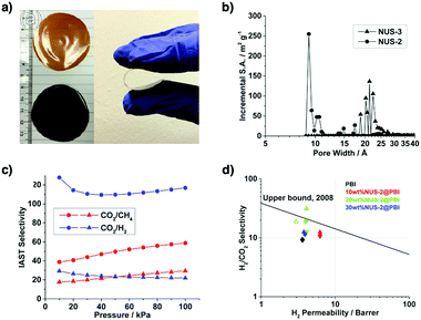 | ||
| Fig. 81 (a) Optical images of 20 wt%NUS-2@Ultem (brown) and 20 wt%NUS-3@Ultem (black). (b) Pore size distributions of NUS-2 and NUS-3. (c) IAST selectivities of NUS-2 (circles) and NUS-3 (triangles) at 273 K. (d) H2/CO2 gas permeation properties of NUS-2@PBI (down triangles, 2 bar; circles, 3.5 bar; up triangles, 5 bar). Solid and hollow symbols represent single gas data and mixed gas data, respectively; the 2008 Robeson upper bound for H2/CO2 separation is included. Adapted with permission from ref. 452, Copyright 2016 ACS. | ||
Layering two COFs with different pore sizes into bilayer structures can reduce their pore sizes, which increases gas adsorption capacity. For example, imine-linked COF-LZU1 (Fig. 67o) with a pore size of 1.8 nm was synthesised on a porous Al2O3 substrate, above which condensation to produce another azine-linked COF (ACOF-1) (Fig. 79c) with a pore width of 0.94 nm was carried out, yielding a COF-LZU1-ACOF-1 bilayer membrane.453 Owing to the interlaced network, the resulting membrane has reduced pore sizes of only 0.3–0.5 nm, which is much smaller than those of individual COFs. As a result, the membrane exhibits a high H2 permeance of 2.45 × 10⁻⁷ mol m−2 s−1 Pa−1 over other bulky gases. In fact, high selectivities of 24.2, 84.0 and 100.2 are achieved for H2/CO2, H2/N2 and H2/CH4, respectively, surpassing the 2008 Robeson upper bounds. Hence, the strategy of overlapping COFs with different pore sizes opens another way to prepare small pores, which complements the pore design of COFs based on topology diagrams and pore surface engineering. How to control precisely the resulting pores is an interesting subject deserving exploration. Recently, COF-LZU1 (Fig. 67o) with 0.3–0.4 nm interlayer spacings has been utilised to separate hydrogen. COF-LZU1 is synthesised onto Amino-CoAl-LDH nano-sheets, which are vertically aligned on α-Al2O3 discs, to fabricate a membrane with a vertical alignment of COF-LZU1 layers. The COF-LZU1 membrane exhibits a hydrogen permeance of 12.06 × 10⁻⁷ mol m−2 s−1 Pa−1 (approximately 3600 GPU) and H2/CO2 and H2/CH4 selectivities of 31.6 and 29.5, respectively.454
10.2 Vapour adsorption
COFs offer 1D nanochannels that are straight and have the same pore size across the material. This is unique as most porous organic polymers consist of amorphous networks that are full of chain interpenetration and entanglement, giving rise to small necks and dead holes across the materials. As such, COFs are expected to be efficient in vapour adsorption, as they enable high-rate uptake owing to their open 1D straight nanochannels.The isotopes of iodine such as 129I and 131I are carcinogenic emissions from nuclear fission. In particular, 129I has a long half-life of 15.7 million years and is a threat to the ecosystem. These influences underpin broad interest in exploring efficient iodine capture materials. Nevertheless, traditional methods such as the use of elemental Ag to form AgI are expensive and low in terms of efficiency.455
To identify the features of 1D channels in the adsorption of iodine, we have explored a series of imine-linked COFs with different topologies, such as hexagonal, tetragonal, trigonal and kagome shapes, as well as different pore sizes and different pore volumes.21 The resulting TPB-DMTP-COF (Fig. 14l), TTA-TTB-COF (Fig. 82a), TTA-TFB-COF (Fig. 82b), TFBCz-PDA-COF (Fig. 67b) and ETTA-TPA-COF (Fig. 82c) have BET surface areas of 1927, 1733, 1163, 1441 and 1822 m2 g−1 and pore volumes of 1.28, 1.01, 0.55, 0.74 and 0.95 cm3 g−1, respectively. CV measurements reveal that these COFs are resistant to oxidation by iodine, suggesting that these COFs are stable for iodine capture. Notably, TPB-DMTP-COF, TTA-TTB-COF, TTA-TFB-COF, TFBCz-PDA-COF and ETTA-TPA-COF exhibit exceptional iodine capture under ambient pressure at 350 K to reach saturation capacities of 6.2, 5.0, 2.7, 3.7 and 4.7 g g−1, respectively (Fig. 83a–c). Notably, these values are nearly the same as the theoretical capacities calculated from the pore volumes of the COFs and the density of iodine.
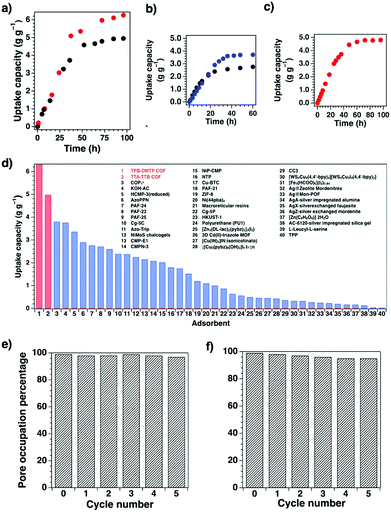 | ||
| Fig. 83 Uptakes of iodine vapour of (a) TPB-DMTP COF (red circles) and TTA-TTB COF (black circles), (b) TTA-TFB COF (black dots) and TFBCz-PDA COF (blue dots) and (c) ETTA-TPA COF as functions of exposure time at 350 K and ambient pressure. (d) Iodine uptake capacities of different adsorbents. Pore accessibilities upon cycling of (e) TPB-DMTP COF and (f) TTA-TTB COF in iodine vapour capture. Adapted with permission from ref. 456, Copyright 2018 Wiley-VCH. | ||
From absorption and infrared spectra, these COFs neither have iodine-attractive sites nor form charge-transfer complexes with iodine, supporting the fact that the spaces of 1D channels are fully accessible to iodine. Thus, the pore volume is the sole factor that determines iodine capture capacity. Remarkably, the capacity of TPB-DMTP-COF is more than two orders of magnitude higher than that of commercially deployed silver-doped zeolite mordenite (Ag-MOR) (Fig. 83d).456 Recycling experiments reveal that their pore accessibilities are retained (>97% for TPB-DMTP-COF and 95% for TTA-TTB-COF) even after three cycles while retaining their crystallinities (Fig. 83e and f). These results suggest that COFs are robust against oxidative iodine and are suitable for practical applications in removing iodine.21 Similarly, in order to expose the nitrogen atoms of imine bonds and π faces to guest molecules, a sterically hindered 1,3,5-trimethyl-2,4,6-tris(4-aminophenyl)-benzene knot has been used to prepare TJNU-201 (Fig. 82d) and TJNU-202 (Fig. 82e). TJNU-201 and TJNU-202 achieve uptake capacities of 5.625 and 4.820 g g−1, respectively.457
SIOC-COF-7 (Fig. 29o) has been developed, which contains hollow microspheres formed by self-assembly of COF particles, where the inner cavities could provide additional volume for iodine storage.102 SIOC-COF-7 with a total pore volume of only 0.41 cm3 g−1 exhibits a high iodine uptake capacity of 4.81 g g−1, indicating that the cavities of the microspheres accounts for 58% of the total capacity. Recently, adsorption of water vapour using COFs has been explored by integrating hydrogen-bonding interactions between hydrophilic COFs and water.458 TpPa-1 COF (Fig. 63e) captures water via water condensation in the pores and achieves capacities of 0.27 and 0.45 g g−1 at 65 and 25 °C, respectively. At temperatures above 40 °C, desorption of water is triggered via an endothermic process, thereby allowing TpPa-1 COF to act as a cooling system. TpPa-1 COF enables 40 consecutive adsorption–desorption cycles with a capacity loss of 0.02 g g−1, illustrating the stability of the β-ketoenamine COF for prolonged and repetitive use.
Interestingly, TpPa-1 COF allows photoactivated water desorption under visible light, opening the possibility of a cooling system controlled by externally stimulating with heat and light. The cooling coefficient, a parameter used to indicate the working efficiency of a cooling adsorbent, is 0.77 at 45–65 °C, which is comparable to MOF-based cooling systems.459 Therefore, integrating hydrophilic groups onto the pore walls to design COFs is an efficient way to water vapour adsorption. In comparison, 3D COF-432 (Fig. 82f) with a nonpolar surface exhibits non-hysteric adsorption and desorption in atmospheric water harvesting.460
10.3 Removal of charged organic species
Removal of charged organic species is based on the chemistry of electrostatic interactions, where attractive forces between cations and anions enable the trapping of oppositely charged ionic species by the skeleton or pore wall. Creating an ionic interface in COFs can introduce two driving forces of selectivity, i.e. dipolar and electrostatic interactions, which are the major driving forces for removing charged organic species, such as organic dyes.Ionic building blocks have been explored for the synthesis of ionic COFs. We have explored cationic linkers for the synthesis of PyTTA-BFBIm-iCOF (Fig. 34c) that allows for the trapping of anionic compounds.84 PyTTA-BFBIm-iCOF exhibits a BET surface area of 1532 m2 g−1 and efficiently removes anionic organic dyes such as methyl orange (MO) from an ethanol/water solution (200 mg L−1). Indeed, time-dependent absorption spectral change reveals a 99.9% decrease in MO concentration within 10 h, while the adsorption kinetic constant is 5.32 × 10⁻² mg g−1, reflecting a rapid uptake process. The maximum removal capacity of PyTTA-BFBIm-iCOF is 553 mg g−1, which is the highest amongst all absorbents. This capacity corresponds to the adsorption of 0.81 MO anion per benzimidazolium cation, indicating a high accessibility of the 1D pore channels of PyTTA-BFBIm-iCOF. This high accessibility originates from an alternate AA stacking mode, such that the cationic sites are homogenously distributed on both sides of the pore walls. Notably, PyTTA-BFBIm-iCOF works well over a wide range of pH values from 1 to 13, and is an ideal adsorbent for various waste sources. Besides, PyTTA-BFBIm-iCOF removes dianionic indigo carmine acid blue 74 (IC-74) with 98.5% efficiency. Interestingly, PyTTA-BFBIm-iCOF can be easily regenerated at room temperature by washing with an aqueous NaBr solution (1.0 M) and the resulting COF retains a removal capacity of 92% of its original after six cycles (Fig. 85).
Similarly, 3D-ionic-COF-1 (pore size = 8.6 Å) and 3D-ionic-COF-2 (pore size = 8.2 Å) (Fig. 84a) consisting of diimidium and ethidium cationic linkers have been prepared for the removal of anions via ion exchange. Both cationic COFs exhibit a rapid (within 20 min) removal of MnO4− anions from their aqueous solution, outperforming other ion-exchange materials. Owing to the resemblance of MnO4− to the radioactive technetium pertechnetate waste, 3D-ionic-COFs are promising for nuclear waste removal. Notably, the 3D-ionic-COFs show a size-exclusion uptake of MO (size = 5.4 × 7.8 × 15.2 Å3), while rejecting methyl blue (MB, size = 13.9 × 14.4 × 24.5 Å3), owing to its larger size compared to the pore dimensions.87 Very recently, integrating β-ketoenamine-linked COFs with graphene oxide has been developed for the preparation of 3D-printed COF-GO foams. Interestingly, the resulting foams with hierarchical pores from micropores to mesopores and macropores show capacities of over 90% to remove organic pollutants such as methylene blue and basic fuchsin from water within one minute.461
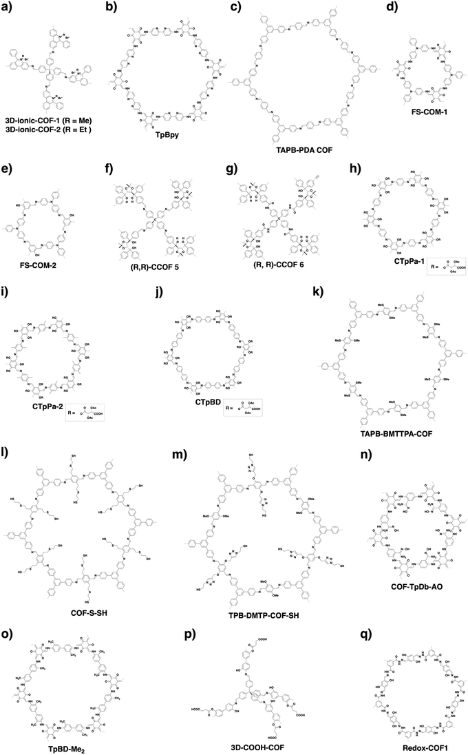 | ||
| Fig. 84 Structures of COFs with (a–c) high affinity to dyes, or designed for (d and e) size exclusion separation, (f–j) chiral separation, (k–n) heavy metal removal and (o–q) other separations. | ||
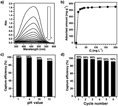 | ||
| Fig. 85 (a) Time-dependent electronic absorption spectral change (from top: 0 min, 1 min, 2 min, 3 min, 5 min, 10 min, 12 min, 15 min, 20 min, 30 min, 1 h, 2 h, 3 h, 5 h and 10 h) of an ethanol/water solution (1/1 by volume, 15 mL) of MO at an initial concentration of 200 mg L−1 upon addition of PyTTA-BFBIm-iCOF (5 mg). (b) Adsorption isotherm of MO. (c) Capture efficiencies of MO at different pH values. (d) Cycling performance. Adapted with permission from ref. 84, Copyright 2017 Wiley-VCH. | ||
Interfacial polymerisation can be used to prepare COF films, wherein the type of interface, monomer and catalyst are key factors in determining the film quality and properties. A Tp-Bpy (Fig. 84b) film has been prepared using a 1,3,5-triformylphloroglucinol (Tp) knot and a bipyridine amine linker (Bpy) at the water–CHCl3 interface in the presence of para-toluene sulphonic acid (PTSA) catalyst. The Tp-Bpy film on a polyester substrate exhibits a high solvent permeance of 339 L m−2 h−1 bar−1 in acetonitrile. It rejects Brilliant Blue-G (94%), Congo red (80%), acid fuchsin (97%) and rhodamine B (98%), demonstrating its potential application in removing organic dyes.462
Similarly, interfacial polymerisation enables the production of a TAPB-PDA COF film (Fig. 84c) with several cm2 size. Notably, the film thickness can be tuned by changing the monomer concentrations. Loading onto a polyethersulphone (PES) membrane yields a composite membrane, which rejects Rhodamine WT with 91% efficiency in an aqueous flux and a permeate flux of 0.24 m3 day−1.463
10.4 Size exclusion separation
Size exclusion separation offers an efficient and energy-saving way to purify molecules with different sizes. COFs with predesignable pore sizes, shapes and environments are expected to serve as a platform for size exclusion separation. The 1D nanochannels are different from 3D hollow vacancies as the channels extend straight and constitute long pores. The channels enable the inclusion of various compounds, from gas molecules to ionic species and even polymers. However, the precise separation of molecules based on their sizes remains difficult for COFs. How to develop these long nanochannels for size exclusion separation is a challenging goal.COFs allow for the design of pore topologies ranging from hexagonal to tetragonal, trigonal and kagome as well as irregular shapes. One promising solution is using the pore topology to constitute a special nanospace to enhance the interactions with guest molecules that enter into the pores, while the pore window can discriminate the sizes of guest molecules. We unexpectedly find that trigonal 1D nanochannels enable the separation of neutral nanosized molecules with a small difference in size.314 We designed HFPTP-BPDA-COF (Fig. 21r), which features dual-pore trigonal 1D channels with pore windows of 1.27 and 1.55 nm and a BET surface area of 1024 m2 g−1. HFPTP-BPDA-COF can take up Nile red (NR, 15.0 Å) but reject 7-(diethylamino)-3-phenylcoumarin (DAPC, 15.5 Å) and Coumarin 6 (C6, 16.8 Å). Remarkably, HFPTP-BPDA-COF completes the uptake of NR from a THF solution within 2 min. In contrast, neither C6 (one-atom different from NR) nor DAPC (similar size to the larger pore) solution shows spectral change in the presence of HFPTP-BPDA-COF even after 12 h. HFPTP-BPDA-COF could also selectively trap NR in the 1D nanochannels from the mixtures with DAPC and C6, leaving DAPC and C6 in the solution phase. Furthermore, an open column with HFPTP-BPDA-COF as the stationary phase enables the separation of NR from DPAC or C6 into pure fractions with infinite selectivity. In contrast, commercial silica gels cannot separate the mixtures. These observations suggest that HFPTP-BPDA-COF separates neutral molecules and recognises the difference of only one atom. Nitrogen sorption isotherm measurements reveal that the 1.55 nm-pore-sized channels are occupied, while the 1.27 nm-pore-sized channels are intact after adsorption of NR.
Each trigonal channel consists of three V-shaped nanogrooves, which are decorated with sequenced zigzag C–H units extruded from the walls. The separation mechanism is elucidated by molecular dynamics simulations at femto-second precision. It was found that the π molecules, when approaching HFPTP-BPDA-COF, adopt an orientation with π backbones parallel to the π-surface of the COF layers to minimise the potential energy. DARP and C6 that are larger than the pore window cannot enter into the channel as the triangular aperture serves as a checkpoint to reject their entry and leaves them outside the pores. Once NR enters the pores, it rotates to assume a diving pose so that it can move in the channel. The NR molecule is finally docked at the corner nanogroove and locked by 9 C–H⋯π interactions with the C–H units and London dispersion forces to gain a total binding energy of 41.1 kcal mol−1. These processes are quick to complete in 10 ps. As each 1D channel has three nanogrooves and confines three single file NR chains, an 18 nm long 1D channel traps 30 NR molecules (Fig. 86). Thus, a cubic crystallite with dimensions of only 500 × 500 × 500 nm3 confines 7![[thin space (1/6-em)]](https://www.rsc.org/images/entities/char_2009.gif) 500
500![[thin space (1/6-em)]](https://www.rsc.org/images/entities/char_2009.gif) 000 NR molecules (Fig. 86, inset).
000 NR molecules (Fig. 86, inset).
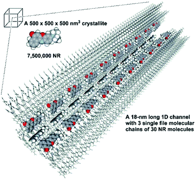 | ||
Fig. 86 A HFPTP-BPDA-COF crystallite with dimensions of 500 × 500 × 500 nm3 confines over 7![[thin space (1/6-em)]](https://www.rsc.org/images/entities/char_2009.gif) 500 500![[thin space (1/6-em)]](https://www.rsc.org/images/entities/char_2009.gif) 000 NR molecules. Inset: Reconstructed structure of a triangular channel in 50 layers over a length of 18 nm for the confinement of 30 NR molecules into three single-file molecular chains at its nanogrooves. Adapted with permission from ref. 314, Copyright 2019 Wiley-VCH. 000 NR molecules. Inset: Reconstructed structure of a triangular channel in 50 layers over a length of 18 nm for the confinement of 30 NR molecules into three single-file molecular chains at its nanogrooves. Adapted with permission from ref. 314, Copyright 2019 Wiley-VCH. | ||
This exceptional function originates from the full accessibility of all channel corners. Investigations of hexagonal and tetragonal COFs with similar pore windows reveal that the hexagonal and tetragonal COFs cannot recognise the difference of these molecules. The π-surface, triangular aperture and built-in C–H sequences on the pore walls work synergistically in HFPTP-BPDA-COF to trigger accurate molecular recognition and size exclusion separation. These results demonstrate a general strategy for designing COFs for molecular recognition and size exclusion separation.
Very recently, sub-microporous FS-COM-1 (Fig. 84d) and FS-COM-2 (Fig. 84e) have been synthesised via interfacial polymerisation as free-standing membranes and used for separation of ions and molecules.464 From NLDFT, experimental PXRD and simulation results, FS-COM-2 has 0.95 nm sized pores with an AA-stacking mode, while FS-COM-1 has 0.6 nm-sized pores with an AB-stacking mode. A similar skeleton structure but with different stacking modes is attributed to the smaller number of hydroxyl groups on the triformylbenzene knot, which hinders the keto–enol tautomerisation, thus changing the interlayer interactions in FS-COM-2. FS-COM-1 shows a water permeance of 38.6 L m−2 h−1 MPa−1, which is 2 times smaller than that (100 L m−2 h−1 MPa−1) of FS-COM-2. An FS-COM-1 membrane allows the passage of protons and rejects 14 metal cations (Na+, K+, Zn2+, Co2+, Ni2+, Ba2+, Mn2+, Sr2+, Sm3+, Gd3+, U3+, La3+, Nd3+ and Ce3+) and rhodamine B (1.7 nm × 1.3 nm). Under 0.1 MPa, FS-COM-1 rejects 90–95% Na2SO4 and K2SO4 in three filtration cycles, which shows potential for sea water desalination.
10.5 Chiral separation
Chiral separation is vital to synthetic chemistry and drug development, as enantiomers are identical in their physicochemical properties but exhibit drastically different biological activities. Chiral separation is typically based on chiral materials that can recognise one of the enantiomers. Chiral COFs are promising for chiral separation as they integrate intrinsic chiral centres onto the pore walls for enantioselective interaction within pores. Their chemical stability, insolubility and open channels offer a chemical basis due to their excellent cyclability.Imine-linked 3D chiral (R,R)-CCOF 5 (Fig. 84f) has been synthesised from the chiral tetraaryl-1,3-dioxolane-4,5-dimethanol (TADDOL) unit and has a surface area of 655 m2 g−1 and pore widths of 0.62 nm and 0.74 nm.466 Oxidation of the imine bond yields amide-linked (R,R)-CCOF 6 (Fig. 84g) with a BET surface area of 613 m2 g−1 and a change in pore width to 0.59 and 0.74 nm. When these chiral COFs are used as stationary phases in a column for HPLC, both COFs can completely or partially separate racemic alcohols, sulphoxides, carboxylic acids and esters. The S-enantiomers tend to elute faster than the R-enantiomers, owing to their weaker interaction with the (R,R)-dihydroxyl groups of the COFs. (R,R)-CCOF 6 achieves baseline resolution for racemates of 1-phenyl-2-propanol, 1-phenyl-1-pentanol, 1-phenyl-1-propanol and 1-(4-bromophenyl)ethanol, while (R,R)-CCOF 5 separates 1-phenyl-2-propanol. (R,R)-CCOF 6 also shows a higher resolution than (R,R)-CCOF 5 under similar conditions, due to enhancements in polarity and stereoselectivity. (R,R)-CCOF 6 has the best selectivity factor of 1.33 and chromatographic resolution of 2.47 for 1-phenyl-1-propanol. Remarkably, the column is efficient even after two months of consecutive runs.
Based on the β-ketoenamine linkage, chiral CTpPa-1 (Fig. 84h) has been constructed using a chiral TP knot to grow in situ onto an amine-modified surface of a gas chromatography (GC) capillary column (Fig. 87a).465 To demonstrate the generality of this method, two other columns containing similar COF structures have been fabricated (CTpPa-2) and CTpBD (Fig. 84i and j). The COF-coated capillary columns are weak in dispersion forces, strong in hydrogen-bonding interactions and moderate in polarity, according to the McReynolds experiments (McReynold constants of 101.9–128.1). In comparison with commercial chiral GC capillary columns, β-DEX 225 and Cyclosil B, the CTpPa-1-bound capillary column achieves better separation with higher resolution. Racemic 1-phenyl-1-propanol and limonene, which are not separated on the commercial columns, are separated on the CTpPa-1-bound capillary column within 5 min. Calculations of thermodynamic parameters show that retention and chiral discrimination of enantiomers in these chiral COF-bound capillary columns are enthalpy driven. Notably, the CTpPa-1 capillary displays consistent performances in run to run (n = 7, relative standard deviation (rsd) = 0.15–0.30%), day to day (n = 5, rsd = 1.11–1.89%) and column to column (n = 3, rsd = 2.35–3.41%), showing potential for applications in chiral separation.
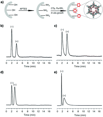 | ||
| Fig. 87 (a) In situ synthesis of chiral COF-bound capillary columns. Gas chromatograms on a CTpPa-1-bound capillary column (30 m long × 0.32 mm inner diameter). (b) (±)-1-Phenylethanol (200 °C, 1.5 mL min−1 N2). (c) (±)-1-Phenyl-1-propanol (200 °C, 2 mL min−1 N2). (d) (±)-Limonene (180 °C, 1.5 mL min−1 N2). (e) (±)-Methyl lactate (170 °C, 1.5 mL min−1 N2). Adapted with permission from ref. 465, Copyright 2016 Springer Nature. | ||
Chirality has been introduced into COFs through post-synthetic modification. For example, TzDa COF (Fig. 55f) condensed from 4,4′,4′-(1,3,5-triazine-2,4,6-triyl)trianiline (Tz) and 1,4-dihydroxyterephthalaldehyde (Da) upon reaction via the hydroxyl units on the pore walls with D-camphoric acid forms chiral CTzDa. Compared to the pristine TzDa COF, CTzDa COF shows a moderate crystallinity, a reduced BET surface area from 1380 to 403 m2 g−1 and a decreased pore size from 3.2 to 1.8 nm. On adsorption of chiral amino acids such as tryptophan, histidine, aspartic acid and serine, CTzDa shows adsorption enantioselectivity values (L/D) of 4.20, 2.59, 2.60 and 1.62, respectively.467
10.6 Removal of metal species
Coordination chemistry explores organic ligands for interaction with metal species to form complexes. A general strategy for removing metal ions is to employ organic ligands to coordinate with metal ions. As a diversity of coordination units are available as building blocks, COFs offer a designable platform for removing metal ions.Imine-linked TAPB-BMTTPA-COF (Fig. 84k) with methyl sulphide units on the pore walls has been explored for the removal of Hg2+ ions from water. TAPB-BMTTPA-COF combines stability, porosity, thioether functional groups and accessibility to achieve an exceptional uptake capacity of 734 mg g−1, which is superior to those of benchmark materials.22 TAPB-BMTTPA-COF can efficiently (>99%) remove Hg2+ ions from water within 5 min (COF 25 mg; 10 ppm; 50 mL, water; pH = 7). TAPB-BMTTPA-COF is selective towards Hg2+ ions, leaving other metal ions intact. Moreover, it works over a wide pH range from 1 to 14 and is recyclable many times while retaining its capacity. Similarly, COF-LZU8 (Fig. 55k) with thioether sites on the pore walls removes Hg2+ ions from water to achieve a Hg2+ ion content of 23.6 wt% in the COF.90 COF-LZU8 is recyclable three times while retaining its crystallinity and sensitivity.
Vinyl-functionalised mesoporous COF-V has been transformed via thiol–ene click reaction to form COF-S-SH with 1,2-ethanedithiol side units on the pore walls (Fig. 84l).91 COF-S-SH exhibits a high capacity to remove Hg2+ ions from water and Hg0 from air (1350 and 863 mg g−1, respectively). Notably, it decreases the Hg2+ ion concentration in water from 5 ppm to 0.1 ppb, a level lower than the requirement (2 ppb) of drinking water. Therefore, the 1D channels with coordination sites on the pore walls are highly accessible to metal ion species while enabling recycled use, owing to the high stabilities of COF materials. Similarly, pore surface engineering based on [HC![[triple bond, length as m-dash]](https://www.rsc.org/images/entities/char_e002.gif) C]0.5-TPB-DMTP-COF through click reaction with a thioether derivative yields TPB-DMTP-COF-SH (Fig. 84m).92 TPB-DMTP-COF-SH shows an exceptional capacity of 4395 mg g−1 for Hg2+. However, assuming that only the sulphur sites trap Hg2+ ions, such a high capacity has yet to be rationalised, as it greatly surpasses the maximum capacity based on the content of thioether units in the COF.
C]0.5-TPB-DMTP-COF through click reaction with a thioether derivative yields TPB-DMTP-COF-SH (Fig. 84m).92 TPB-DMTP-COF-SH shows an exceptional capacity of 4395 mg g−1 for Hg2+. However, assuming that only the sulphur sites trap Hg2+ ions, such a high capacity has yet to be rationalised, as it greatly surpasses the maximum capacity based on the content of thioether units in the COF.
COF-LZU1 (Fig. 67o) with Ag nanoparticles in the pores reduces Hg2+ ions to Hg0, and forms an amalgam with Ag to produce Ag NPs@COF-LZU1. Ag NPs@COF-LZU1 achieves a Hg2+ removal efficiency of 99% and is selective towards other transition metals such as Cu(II), Ca(II), Zn(II), Mg(II) and Cd(II).468
COF-TpDb-AO (Fig. 84n) possesses amidoxime units that can coordinate with uranium ions and exhibits a removal capacity of 408 mg g−1, which is higher than that (355 mg g−1) of the amorphous analogue, POP-TpDb-AO. Notably, COF-TpDb-AO reaches 95% equilibrium adsorption efficiency within 30 min, while POP-TpDb-AO is sluggish and takes 90 min under otherwise similar conditions. This opens the way to removing radioactive metal species from seawater.95
10.7 Separation of other species
COFs have been developed to capture and separate various compounds including aryl-organophosphorus flame retardants,469 perfluoroalkyl compounds,99 phenol endocrine disruptors,470,471 pesticides,472–475 carcinogens,476,477 lactic acid,478 biotoxins from seawater,479 lanthanides,480 radionuclides,95,97,210 pharmaceutical contaminants,481–485 nanoparticles,486 oil spills,487 food quality markers,488,489 and biomarkers for diagnosis.490Magnetic solid-phase extraction (MSPE) of marine biotoxins from seawater was efficiently realised with a magnetic COF composite, mTpBD-Me2 (Fig. 84o). Amino-functionalised Fe3O4 was prepared from dopamine (DOPA) to produce magnetic nanoparticles, Fe3O4@DOPA. Subsequent functionalisation with Tp knots gives Fe3O4@DOPA-Tp, which is then used to synthesise mTpBd-Me2 by the addition of different amounts of Tp and o-tolidine linker. The optimised material, 0.2-mTpBD-Me2 (0.2 mmol Tp/0.3 mmol o-tolidine for 50 mg Fe3O4@DOPA-Tp), has a high surface area of 538 m2 g−1 and is used for MSPE application. At 19 °C and an initial concentration of 100 μM, the MSPE adsorption capacities of mTpBD-Me2 for biotoxins okadaic acid (OA) and dinophysistoxin-1 (DTX-1) are 812 and 830 mg g−1, respectively. These values are 500-fold for OA and 300-fold for DTX-1 compared to the commercial microporous resins HP20 and SP700, as a result of the high accessibility of open channels of COFs. Moreover, 0.2-mTpBD-Me2 shows 3-fold adsorption capacity compared to pure TpBD-Me2, owing to the higher efficiency of magnetic retrieval of the adsorbent than that of centrifugation separation. Desorption of the adsorbate biotoxins with 2-propanol at 4 °C overnight achieves 97% recovery, while five adsorption–desorption cycles of 0.2-mTpBD-Me2 for OA show a final decrease of 12% in adsorption efficiency. In addition, adsorption equilibrium is reached within 60 min, showing the affinity and accessibility of pores to the biotoxins.479
3D-COOH-COF (Fig. 84p) is post-synthetically functionalised from 3D-OH-COF and shows selective separation of radioactive Nd3+ ions from Nd3+/Fe3+ and Sr2+/Fe3+ mixture solutions. 3D-OH-COF is first synthesised from a tetrahedral knot, tetra(4-formylphenyl)methane (TFPM), and a hydroxy group-containing linker, 3,3′-dihydroxybenzidine (DHBD), giving a dia net structure. Post-synthetic functionalisation with succinic anhydride through ring-opening reaction produces 3D-COOH-COF, which retains the crystallinity but has a reduced BET surface area (from 1077 to 540 m2 g−1) and reduced pore size (from 1.31 to 0.68 nm). Metal ion uptake is first analysed in separate solutions of Nd3+, Fe3+ and Sr2+. At 3 mM Nd3+ concentration, the amount adsorbed in 3D-COOH-COF is 0.7 mmol g−1, surpassing that of pristine 3D-OH-COF (∼0.05 mmol g−1), showcasing the strong extraction power of the carboxyl groups. Nd3+ adsorption isotherms of 3D-COOH-COF show the steepest rise, with a Langmuir parameter of 15.87 m M−1, larger than those of Fe3+ (0.08 m M−1) and Sr2+ (0.85 m M−1). This is because Nd3+ with a larger ionic radius and greater charge density can match better with the binding pockets in 3D-COOH-COF. Solid-state 13C NMR and XPS results further prove that carboxyl groups bind more strongly to Nd3+ than to Fe3+ and Sr3+. The IAST selectivities for adsorption in 5% Nd3+/95% Fe3+ and 5% Nd3+/95% Sr2+ with a total concentration of 0.1 mM are 27 and 18, respectively. This indicates the good extraction efficiency of 3D-COOH-COF for Nd3+. 3D-COOH-COF was used at least 3 times without significant loss of capacity.480
To tackle the problem of nuclear waste processing, a redox-active COF, i.e. Redox-COF1 (Fig. 84q), is developed for the solid-state extraction of radionuclides. Synthesised by interfacial polymerisation, Redox-COF1 has lower crystallinity and surface area than its 2D COF counterpart. Redox-COF1 is thermally stable up to 350 °C and stable in acid. Interestingly, upon UO22+ sorption, a Redox-COF1 dispersion shows a colour change from yellow to brown. XPS measurements reveal that after adsorption C–O is oxidised to C![[double bond, length as m-dash]](https://www.rsc.org/images/entities/char_e001.gif) O, while U(VI) is reduced to U(IV). The EPR signal at g = 1.99 further supports the redox process. DFT calculations elucidate a two-step redox process, in which the N atoms in the COF play a vital role in conjugation extension and coordination with UO22+, facilitating electron transfer from O atoms to uranium. In a multi-ion solution (in which the concentration of each ion is 1.0 mmol L−1), Redox-COF1 shows over 90% selective adsorption of UO22+ over 11 competing metal ions, across a pH range between 2 and 4.5. The best performance is achieved at pH = 3, where the selectivity reaches 97%. At pH = 4.5, Redox-COF1 shows a uranium uptake capacity of 0.991 mmol g−1 and a selectivity of 96%. Under otherwise similar conditions, a control COF without hydroxyl groups exhibits a capacity of only 0.065 mmol g−1 and a selectivity of 13%.97
O, while U(VI) is reduced to U(IV). The EPR signal at g = 1.99 further supports the redox process. DFT calculations elucidate a two-step redox process, in which the N atoms in the COF play a vital role in conjugation extension and coordination with UO22+, facilitating electron transfer from O atoms to uranium. In a multi-ion solution (in which the concentration of each ion is 1.0 mmol L−1), Redox-COF1 shows over 90% selective adsorption of UO22+ over 11 competing metal ions, across a pH range between 2 and 4.5. The best performance is achieved at pH = 3, where the selectivity reaches 97%. At pH = 4.5, Redox-COF1 shows a uranium uptake capacity of 0.991 mmol g−1 and a selectivity of 96%. Under otherwise similar conditions, a control COF without hydroxyl groups exhibits a capacity of only 0.065 mmol g−1 and a selectivity of 13%.97
11. Catalytic systems
Catalysis plays a key role in modern chemical processes and is critical in the development of a prosperous society. Most reactions are energy demanding and organic transformation shares a huge portion of energy consumption. Hence, exploring a stable, recyclable and efficient catalyst is a fundamental subject in the chemistry field.491,492 In this context, heterogenous catalysis offers the most promising technology for chemical transformation and attracts increasing attention. Traditional heterogeneous catalysts based on inorganic and polymeric supports suffer from low efficiency, active site shielding, disordered distribution and leakage. In contrast, COFs offer an attractive platform for designing insoluble and stable catalysts and enable tailor-made skeletons and pores for specific transformations (refer to Section 2.5 Catalytic units).Distinct from other porous frameworks, COFs are unique in that they combine different features such as designability, stability and porosity in one material. Firstly, COFs enable the precise integration of various catalytic species to form ordered catalytic environments and create local interfaces with controlled π cloud density, spatial alignment and restriction. Combining these features of homogeneous catalysts, COFs are able to predesign reaction routes and to improve reaction selectivity. Moreover, COFs create new features for heterogeneous catalysis, such as crystalline skeletons to promote charge transport and 1D channels to facilitate transport of ions and molecules. Combining features of homogeneous and heterogeneous catalysts in one material, COFs offer a unique platform for designing heterogeneous catalytic systems.
COFs have been explored using different chemistries to design heterogenous catalysts (Scheme 9). Designing COF-based catalysts means not only shaping catalytic centres but also controlling catalytic interfaces. Design of π electronic interfaces controls exciton motion, electron transfer, and charge separation; local interface design sets chemical environments around catalytic centres, whereas pore interface design predetermines pore size, shape and walls. π interfaces include π units, linkages, backbone topologies and molecular orbitals, while local interfaces embody spatial alignment, redox states and environments of catalytic centres, and pore interfaces include pore shape, size and walls. These designs are distinct from those of molecular catalysts. For these reasons, COF-based catalysts require more systematic interface management over long spatial and time ranges.
With the above design principles, COF-based catalysts have been explored via four structural origins, including (1) skeleton and pore wall design, (2) pore surface engineering, (3) physical encapsulation and (4) systematic integration (Scheme 9). As such, COF-based catalysts have been developed with different strategies and used for diverse conversions.
11.1 Photocatalysis
COFs can be designed and synthesised with various π units and constitute a diversity of semiconductors, which function as photocatalysts for promoting various reactions. We categorise photocatalysis into different reactions as they proceed via different excited states and involve different photochemical processes.Porphyrin MP-DHPh COFs (Fig. 88a) have been developed as heterogeneous catalysts for the generation of singlet oxygen.164 By integrating intralayer hydrogen-bonding phenolic sites, tetragonal sheets are designed to have a greater planarity, allowing for a higher crystallinity and porosity. This in turn enhances light harvesting capabilities, reduces the band gap and promotes triplet oxygen excitation. CuP-DHPh COF exhibits a small band gap of 1.36 eV and is 10 to 20-fold more active than monomeric CuTPP, CuP-linear polymer and amorphous CuP-Ph polymer (Fig. 89). These findings highlight the important role that intralayer hydrogen bonds play in governing the physical properties of COFs.
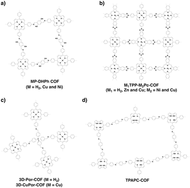 | ||
| Fig. 88 Structures of COFs with porphyrin or phthalocyanine knots for photocatalytic oxygen activation. | ||
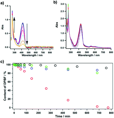 | ||
| Fig. 89 Absorption spectral changes of DPBF in the presence of (a) CuP-DHPh COF and (b) the amorphous CuP-Ph polymer, in an oxygen-saturated DMF solution upon irradiation at 500 nm. (c) Effects of different photocatalysts (0.5 mg) on the reaction (black: monomeric CuTPP; blue: CuP-linear polymer; green: amorphous CuP-Ph polymer; red: CuP-DHPh COF). Note: 1,3-diphenylisobenzofuran (DPBF) is a label for singlet oxygen generation. Adapted with permission from ref. 164, Copyright 2015 ACS. | ||
To take full advantage of the light-harvesting capabilities of porphyrin and phthalocyanine units, a series of porphyrin-co-phthalocyanine COFs, M1TPP-M2Pc-COF and M1DPP-M2Pc-COF (Fig. 88b and 25f), have been prepared. Attributed to the synergistic absorption effects of the porphyrin and phthalocyanine units, these COFs show absorption over the entire range of the visible spectrum, extending into the near-infrared region of up to 1350 nm. Under irradiation with 500 nm light, ZnTPP-CuPc-COF is active in producing molecular oxygen to achieve an efficiency that is more than three orders of magnitude higher compared to its monomer mixture. The porphyrin-co-phthalocyanine COFs also show activity one order of magnitude higher compared to CuP-SQ COF.44
Our findings drew inspirations from a wave of investigations into singlet oxygen generation and its subsequent applications. Some examples are porphyrin 3D-Por-COF and 3D-CuPor-COF (Fig. 88c). 3D-Por-COF and 3D-CuPor-COF have high BET surface areas of 1398 and 1335 m2 g−1, respectively, while their 3D structures endow the porphyrin sites with high accessibility to molecular oxygen.165 Interestingly, singlet oxygen generated in situ can oxidise sulphides to sulphoxides, avoiding conventional harsh conditions as well as the problem of over-oxidation to sulphones. These COFs tolerate a broad substrate scope and promote reactions with high efficiency, selectivity and recyclability, opening the way to sulphoxidation.166,493
Besides porphyrin-based COFs, desymmetrised TPAPC-COF (Fig. 88d) has been produced by using the C2-symmetric corrole knot. TPAPC-COF adopts a dissymmetric hcb topology and exhibits an absorption edge of up to 2000 nm. As a result of its small band gap of 1.06 eV, TPAPC-COF is able to generate singlet oxygen upon irradiation at 635 nm. Taking advantage of its negligible toxicity, TPAPC-COF was composited with DSPE-PEG2000 to produce singlet oxygen to kill MCF-7 human breast carcinoma cells. Notably, less than 15% of cancer cells survived after 10 min of laser irradiation at 635 nm.28
A series of azine-linked COFs have been developed for hydrogen evolution. Amongst the tested Nx-COFs, N3-COF (Fig. 90b) shows a remarkable hydrogen evolution rate of 1.703 mmol h−1 g−1 (Fig. 91), which is better than those of carbon nitride compounds. The high planarity of the triazine knot, together with the fully conjugated network, allows for a suitable band gap of 2.6–2.7 eV. Its high crystallinity promotes exciton migration and charge separation. The lower HOMO level and facile hydrogen-bonding between the triazine unit and the sacrificial donor TEOA assist in the quenching of holes. The electron deficient triazine stabilises the negative charge on N3-COF and transfers it to the platinum reaction centre to produce hydrogen.169 Despite being isoelectronic to N3-COF, PTP-COF (Fig. 90c) achieves a hydrogen evolution rate of 83.83 μmol h−1 g−1. This low activity results from its low crystallinity, porosity and surface area compared to N3-COF.171 In addition to the azine-linked hexagonal Nx-COFs, azine-linked rhombic A-TEBPY-COF with pyrene knots (Fig. 90d) has been developed for hydrogen evolution to achieve a rate of 98 μmol h−1 g−1.494 Apart from hydrazone and azine-linked COFs, β-ketoenamine-linked diacetylene-functionalised TP-BDDA COF has been investigated for photocatalytic hydrogen evolution (Fig. 90e), owing to its conjugated structure together with an abundance of active sites for charge transfer. With a band gap of 2.31 eV, a surface area of 758 m2 g−1 and facile transport of photogenerated electrons to the Pt interface, TP-BDDA COF achieves a hydrogen evolution rate of 324 μmol h−1 g−1, while retaining its structural integrity after 10 h reaction. This is more efficient than acetylene (TP-EDDA) and phenyl (TP-DTP) containing COFs (Fig. 92a and b). This work shows the possibility of using different functional subunits and linkages to design photocatalysts, demonstrating the designability and structural superiority of COFs.173
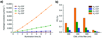 | ||
| Fig. 91 (a) Hydrogen production monitored over 8 h using Nx-COFs as a photocatalyst in the presence of triethanolamine as a sacrificial electron donor. (b) Photonic efficiency (PE) measured with four different band-pass filters with central wavelengths (CWLs) of 400, 450, 500 and 550 nm. Adapted with permission from ref. 169, Copyright 2015 Springer Nature. | ||
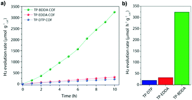 | ||
| Fig. 92 (a) Photocatalytic hydrogen evolution performances of TP-BDDA, TP-EDDA and TP-DTP catalysts under visible light irradiation (≥395 nm) using TEOA as a sacrificial agent. (b) Comparison of photocatalytic hydrogen evolution rates. Adapted with permission from ref. 173, Copyright 2018 ACS. | ||
Motivated by a remarkable hydrogen evolution rate (3.26 mmol h−1 g−1) observed for a linear conjugated polymer containing the dibenzo[b,d]thiophene sulphone (DBTS) unit, the DBTS unit has been incorporated into a β-ketoenamine-linked COF to prepare FS-COF (Fig. 90f). Owing to the chemical stability of β-ketoenamine and the planarity of the linker unit, FS-COF exhibits long-range structural ordering and stability, enabling prolonged use without compromising its catalytic performance. FS-COF has a BET surface area of 1288 m2 g−1, a good wettability with a contact angle of 23.6°, a high uptake of water of 67 wt% and a long excited-state lifetime of 5.56 ns. FS-COF exhibits a hydrogen evolution rate of 10.1 mmol h−1 g−1 and 16.3 mmol h−1 g−1 when co-sensitised with WS5F, in the presence of sodium ascorbate as the sacrificial electron donor and Pt as the reaction centre. It is also stable after 50 h photolysis in water. This performance is superior to those of β-ketoenamine based COFs such as Eosin Y sensitised Pd0/TpPa-1 (10.4 mmol h−1 g−1)174 and TpPa-COF-(CH3)2 (8.33 mmol h−1 g−1).495 This study showcases the importance of wettability in designing efficient photocatalysts to produce hydrogen from water.496
Despite their remarkable hydrogen evolution rates, most COFs require platinum as the reaction centre to reduce water. Replacing platinum with a chloro(pyridine)cobaloxime reaction centre enables a noble metal-free photocatalytic system based on N2-COF (Fig. 90g). N2-COF triggers an outer sphere electron transfer to chloro(pyridine)cobaloxime and achieves a hydrogen evolution rate of 782 μmol h−1 g−1.172 Moreover, by replacing Pt with a Ni-thiolate cluster, the β-ketoenamine-linked TpDTz COF (Fig. 90h) achieves a hydrogen evolution rate of 941 μmol h−1 g−1.175 These strategies provide a viable alternative to traditional methods. In a similar fashion, a nickel hydroxide-modified COF composite, Ni(OH)2-2.5%/TpPa-2, has been developed, which exhibits a hydrogen evolution rate of 1.896 mmol h−1 g−1.497 Although efficient hydrogen production from COFs involves an interplay of several photochemical processes, co-acquisition of all these favourable factors is usually difficult. This severely complicates the structural design of COFs as no clear structure–property–activity relationship has been revealed. Hence, it is of utmost importance to identify the key factors governing the photocatalytic hydrogen evolution of COFs to direct future developments in this area.
Recently, a series of β-ketoenamine COFs consisting of different linker units were synthesised (Fig. 90i). Specifically, these linker units have different electron donating (anthracene, Ant; terphenyl, Tp) and accepting abilities (benzothiadiazole, Bt; tetrazine, Tz) and torsional angles (Ant (66°) > Bt (39°) > Tp (27°) > Tz (0°)). Two different sets of conditions (COF120: mesitylene![[thin space (1/6-em)]](https://www.rsc.org/images/entities/char_2009.gif) :
:![[thin space (1/6-em)]](https://www.rsc.org/images/entities/char_2009.gif) dioxane (4
dioxane (4![[thin space (1/6-em)]](https://www.rsc.org/images/entities/char_2009.gif) :
:![[thin space (1/6-em)]](https://www.rsc.org/images/entities/char_2009.gif) 1), 6 M AcOH, 120 °C, 7 days; COF150: mesitylene
1), 6 M AcOH, 120 °C, 7 days; COF150: mesitylene![[thin space (1/6-em)]](https://www.rsc.org/images/entities/char_2009.gif) :
:![[thin space (1/6-em)]](https://www.rsc.org/images/entities/char_2009.gif) dioxane (1
dioxane (1![[thin space (1/6-em)]](https://www.rsc.org/images/entities/char_2009.gif) :
:![[thin space (1/6-em)]](https://www.rsc.org/images/entities/char_2009.gif) 2), 6 M AcOH, 150 °C, 3 days) are used to investigate the effect of their surface area, crystallinity and stacking mode on hydrogen evolution. As a result, BtCOF150 exhibits the highest hydrogen evolution rate of 750 ± 25 μmol h−1 g−1 (Fig. 93). Although BtCOF150 neither has the highest surface area and crystallinity nor the most favourably positioned LUMO level, it possesses the highest light absorption area and charge carrier generation ability, which is a result of the aligned donor–acceptor columnar arrays. This study reveals that light absorption and charge carrier generation and transport are key to hydrogen evolution.498
2), 6 M AcOH, 150 °C, 3 days) are used to investigate the effect of their surface area, crystallinity and stacking mode on hydrogen evolution. As a result, BtCOF150 exhibits the highest hydrogen evolution rate of 750 ± 25 μmol h−1 g−1 (Fig. 93). Although BtCOF150 neither has the highest surface area and crystallinity nor the most favourably positioned LUMO level, it possesses the highest light absorption area and charge carrier generation ability, which is a result of the aligned donor–acceptor columnar arrays. This study reveals that light absorption and charge carrier generation and transport are key to hydrogen evolution.498
 | ||
| Fig. 93 Torsional angles, surface areas, crystallinities, photophysical properties and rates of H2 evolution of all of the COFs. Adapted with permission from ref. 498, Copyright 2020 ACS. | ||
β-Ketoenamine-linked COFs have been used to prepare various hybrids such as CdS–COF hybrids,499 COF-modified g-C3N4,500 MoS2/TpPa-1 hybrids501 and [Mo3S13]2− cluster encapsulating Mo3S13@EB-COF.502 However, a small increment of the hydrogen evolution rate compared to the individual COFs does not justify these complex hybrid systems with heavy metals. Recently, a MOF/COF hybrid has been prepared by covalently linking NH2-UiO-66 onto the surface of TpPa-1 COF. Combining the chemical stability and photo-absorption capability of TpPa-1 COF with the catalytic activity of NH2-UiO-66 MOF, the NH2-UiO-66/TpPa-1 COF hybrid is able to achieve a hydrogen evolution rate of 23.42 mmol h−1 g−1. Under such circumstances, the NH2-UiO-66/TpPa-1 COF hybrid forms heterojunctions which facilitate charge separation and reduce charge recombination.503
Designing photocatalytic COFs for hydrogen evolution still lacks a general strategy for tackling a series of consecutive photochemical processes including light harvesting, exciton migration and splitting, and charge transport and charge transfer. Hence, there is an urgent need to establish a principle for designing COFs. Recently, we have explored a sp2 carbon-conjugated framework, i.e. sp2c-COFERDN, by integrating electron deficient 3-ethylrhodanine (ERDN) units as the end-capping group of sp2c-COF to constitute electron donor–acceptor heterojunctions (Fig. 90j). sp2c-COFERDN is unique as it enables a seamless integration of photochemical processes to promote hydrogen evolution. The fully π-conjugated lattice extends the light absorbance to 800 nm, the well-aligned π arrays promote exciton migration and charge carrier transport, the heterojunctions facilitate exciton splitting, and loading Pt reaction centres into the pores or onto the surface greatly shortens the electron-transferring distance from the COF to the Pt centre. These features connect the consecutive photochemical processes in a seamless way. sp2c-COFERDN (100 mg) achieves a hydrogen evolution rate of 2.12 mmol h−1 g−1 when irradiated with light ≥420 nm (Fig. 94a) and retains a rate of 1.24 mmol h−1 g−1 upon irradiation with light ≥495 nm (Fig. 94b). Apparent quantum yields (AQYs) of 0.46 to 0.2% were also achieved by irradiation with 420 to 578 nm light (Fig. 94c). sp2c-COFERDN is robust and retains crystallinity, porosity and efficiency after 20 h continuous reaction (Fig. 94d).
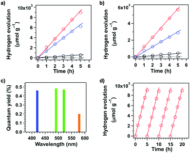 | ||
| Fig. 94 Hydrogen production monitored over 5 h with sp2c-COF (blue circles), sp2c-COFERDN (red circles), sp2c-CMP (black circles) and an imine-linked pyrene COF (triangles) as photocatalysts under irradiation with (a) wavelengths ≥420 nm and (b) wavelengths ≥495 nm. (c) Apparent quantum yields (AQYs) of sp2c-COFERDN under irradiation with monochromatic light at 420 nm (blue bar), 490 nm (green bar), 520 nm (deep green bar) and 578 nm (orange bar). (d) Stability of sp2c-COFERDN over four prolonged repeated photocatalytic operations under irradiation ≥420 nm. Adapted with permission from ref. 183, Copyright 2019 Elsevier Inc. | ||
sp2c-COF possesses a low HOMO level that is suitable for water oxidation to produce oxygen. Indeed, sp2c-COF (50 mg) produces oxygen at a rate of 22 μmol h−1 g−1 upon irradiation of an aqueous solution (100 mL) with La2O3 pH buffer agent (0.2 g), AgNO3 electron acceptor (0.01 M) and Co(NO3)2 co-catalyst (0.6 mg). Therefore, sp2c-COFs upon coupling with suitable reduction and oxidation reaction centres enable the design of photocatalysts to achieve a full splitting of water.183
Taking the features of sp2c-COFs, C![[double bond, length as m-dash]](https://www.rsc.org/images/entities/char_e001.gif) C linked g-C40N3-COF (Fig. 15g) has been prepared via Knoevenagel condensation. g-C40N3-COF shows a band gap of 2.36 eV and a fluorescence lifetime of 3.31 ns. It is ambipolar and facilitates electron and hole transport. Coordination of the Pt reaction centre with the pyridinyl nitrogen promotes electron transfer. g-C40N3-COF achieves a hydrogen evolution rate of 4.12 mmol h−1 g−1 and an oxygen evolution rate of 50 μmol h−1 g−1 in separated systems.19 Similarly, triazine g-C18N3-COF (Fig. 90k) exhibits a hydrogen evolution rate of only 292 μmol h−1 g−1, although it has a fluorescence lifetime of 7.25 ns.504
C linked g-C40N3-COF (Fig. 15g) has been prepared via Knoevenagel condensation. g-C40N3-COF shows a band gap of 2.36 eV and a fluorescence lifetime of 3.31 ns. It is ambipolar and facilitates electron and hole transport. Coordination of the Pt reaction centre with the pyridinyl nitrogen promotes electron transfer. g-C40N3-COF achieves a hydrogen evolution rate of 4.12 mmol h−1 g−1 and an oxygen evolution rate of 50 μmol h−1 g−1 in separated systems.19 Similarly, triazine g-C18N3-COF (Fig. 90k) exhibits a hydrogen evolution rate of only 292 μmol h−1 g−1, although it has a fluorescence lifetime of 7.25 ns.504
A general design strategy is to integrate redox-active transition metal sites onto COF backbones to serve as photocatalytic centres for reduction of CO2. For example, Re-COF (Fig. 90m) has been developed by post-synthetic ligation of Re(I) to the bipyridine linker. Re-COF possesses extended π-conjugation and chemical stability and is able to act as a photosensitiser and a support to isolate the Re complex for efficient charge separation. As a result, photoinduced electron transfer proceeds from the photoexcited COF skeleton to the Re complex where CO2 is reduced to CO. Re-COF achieves a CO evolution rate of about 0.75 mmol h−1 g−1 with 98% selectivity,170 which is superior to that of rhenium-functionalised Re-TpBpy (Fig. 90n) with a rate of about 0.28 mmol h−1 g−1.176 In contrast, Ni-TpBpy (Fig. 90o) exhibits a CO evolution rate of 0.966 mmol h−1 g−1 with 96% selectivity in the presence of (Ru(bpy)3)Cl2, which serves as a visible light photosensitiser (Fig. 95a). However, this system is unstable as Ru(bpy)32+ dye degrades, while Ni-TpBpy leaks Ni(II) ions (Fig. 95b). Mechanistic studies reveal an important role of the β-ketoenamine knot in achieving high selectivity by stabilising the COF-Ni-CO2H intermediate via hydrogen bonds.177 Co(II) and Zn(II) ions have been integrated into an anthraquinone DQTP COF (Fig. 63a) to form DQTP COF-Co and DQTP COF-Zn via coordination with carbonyl groups. DQTP COF-Co exhibits a CO evolution rate of 1.02 mmol h−1 g−1 with a selectivity of 59.4%, while DQTP COF-Zn shows a HCOOH evolution rate of 0.1525 mmol h−1 g−1 with a selectivity of 90% upon irradiation with ≥420 nm in acetonitrile, with TEOA as a sacrificial donor.375
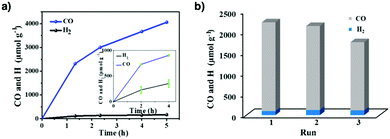 | ||
| Fig. 95 (a) Photocatalytic evolutions of CO and H2 by Ni-TpBpy under 1 and 0.1 atm (diluted with Ar, inset) and (b) stability tests of Ni-TpBpy for selective photoreduction of CO2. Adapted with permission from ref. 177, Copyright 2019 ACS. | ||
Based on the structure of sp2c-COF-2 prepared by our group previously, Bpy-sp2c-COF with bipyridine linkers has been produced. Subsequent chelation with Re(I) yields Re-Bpy-sp2c-COF (Fig. 90p) that exhibits a CO production rate of 1.04 mmol h−1 g−1 with 81% selectivity, which is improved to 1.40 mmol h−1 g−1 with 86% selectivity by introducing a dye sensitiser. Compared to imine-linked Re-COF (Fig. 90m) and Re-TpBpy (Fig. 90n) which are partially conjugated, C![[double bond, length as m-dash]](https://www.rsc.org/images/entities/char_e001.gif) C linked Bpy-sp2c-COF has a fully π-conjugated skeleton and promotes the sequence of photochemical events after photoirradiation. This further highlights the importance of C
C linked Bpy-sp2c-COF has a fully π-conjugated skeleton and promotes the sequence of photochemical events after photoirradiation. This further highlights the importance of C![[double bond, length as m-dash]](https://www.rsc.org/images/entities/char_e001.gif) C linkages for photocatalytic applications.506
C linkages for photocatalytic applications.506
Compared to bulk COFs, 2D COF nanosheets (NSs) have larger surface area and more accessible catalytic sites which are beneficial for photocatalytic reactions. Using a general imine-exchange approach with sterically hindered 2,4,6-trimethylbenzaldehyde, a series of porphyrin and metalloporphyrin-based 2D COF NSs have been prepared. In particular, COF-367-Co (Fig. 90q) NSs have thicknesses of only 1.0–1.2 nm and exhibit a remarkable CO evolution rate of 10.162 mmol h−1 g−1 with 78% selectivity in the presence of the [Ru(bpy)3]Cl2 photosensitiser and ascorbic acid sacrificial donor. This is almost two orders of magnitude higher than that (0.124 mmol h−1 g−1) of bulk COF-367-Co.507 Therefore, in addition to the skeleton, the layer structure should also be considered for catalyst design.
The photocatalytic systems mentioned above require the use of sacrificial electron donors; such systems are not green as sacrificial donors impair the system by producing undesirable by-products. Therefore, an important and urgent task is to circumvent the use of sacrificial donors. Azine-linked ACOF-1 (Fig. 79c) and N3-COF (Fig. 90b) have been developed for photoreduction of CO2 using water as an electron donor. ACOF-1 and N3-COF have a band gap of 2.69 eV and 2.57 eV, respectively, with favourable HOMO and LUMO levels of −5.00 and −2.54 eV for ACOF-1 and −4.95 and −2.71 eV for N3-COF for CO2 photoreduction using water as the electron donor. Under visible light (800 nm ≥ λ ≥ 420 nm), N3-COF achieves a methanol production rate of 0.57 μmol h−1 g−1, while ACOF-1 achieves a rate of 0.36 μmol h−1 g−1, using 10 mg of photocatalyst in 5 mL deionised water; both are more active than g-C3N4 (0.2 μmol h−1 g−1). The activity of N3-COF is attributed to its high BET surface area of 1412 m2 g−1 to adsorb CO2 with the assistance of CO2-philic azine linkers. Moreover, the conjugated backbone and optimised π cloud distributions at the HOMO and LUMO levels promote charge separation by reducing charge recombination.320
Very recently, imine-linked TTCOF-M has been constructed by condensing TTF with porphyrin or metalloporphyrin monomer. This system does not require additional photosensitisers nor sacrificial donors. Among different metal species, TTCOF-Zn (Fig. 96a) has a LUMO level of −4.27 eV and a HOMO level of −5.76 eV, which are suitable for CO2 reduction and water oxidation, respectively. TTCOF-Zn exhibits the highest rate of 2.055 μmol h−1 g−1 with an almost 100% selectivity in CO production (Fig. 97a). Upon irradiation, electrons are excited from the HOMO located on the TTF unit to the LUMO located on the porphyrin unit. CO2 is reduced by electrons from porphyrin, while water is oxidised to donate electrons to TTF, thereby completing the catalytic cycle. TTCOF-Zn is reused more than five times without any obvious decrease in catalytic activity (Fig. 97b).508 This work offers a rational method using donor–acceptor monomers to construct COFs with a unique structure–function relationship that is critical for carbon dioxide photoreduction. Studies along this direction will open a stage for designing photocatalysts to convert CO2 into various value-added chemicals driven by sunlight and water.
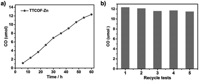 | ||
| Fig. 97 (a) Time-dependent CO production performance using TTCOF-Zn as a photocatalyst. (b) Durability tests of TTCOF-Zn. Adapted with permission from ref. 508, Copyright 2019 Wiley-VCH. | ||
Taking advantage of the donor–acceptor approach, terephthalaldehyde linkers of COF-366 (Fig. 35c) are replaced with the more electron-withdrawing 2,5-dibromo-terephthaladehyde to produce TAPBB-COF (Fig. 96b). Although TAPBB-COF has a similar conduction band (−0.83 V vs. NHE) to COF-366 (−0.88 V), it has a more positive valence band (1.10 V) than COF-366 (0.86 V). As a result of the greater difference between the valence band and the O2/H2O redox potential (0.82 V), water can be used more efficiently as the sacrificial donor. As such, TAPBB-COF exhibits a higher CO2 photoreduction rate of 24.6 μmol h−1 g−1 than COF-366 (8.5 μmol h−1 g−1) when irradiated with simulated sunlight (1000 nm ≥ λ ≥ 200 nm). The photoreduction proceeds with 95.6% CO selectivity. Even under visible light irradiation (λ ≥ 430 nm), a relatively high rate of 12.4 μmol h−1 g−1 is sustained for more than five cycles.510 This result demonstrates that the incorporation of electron-withdrawing bromine is a good option to modify the electronic structure of COFs.
The combination of a triazine knot and a carbazole linker produces donor–acceptor CT-COF (Fig. 96c). Although CT-COF has a very similar conduction band of −0.88 V and a valence band of 1.16 V (Fig. 98a) to those (−0.83 and 1.10 V) of TAPBB-COF, the CO evolution rate reaches 102.7 μmol h−1 g−1 under visible light irradiation (λ ≥ 430 nm), which is 68.5 times higher than that (1.5 μmol h−1 g−1) of g-C3N4. This is by far the best performing metal-free photocatalyst for CO2 reduction in water, even outperforming some recent metal-containing COF photocatalysts such as TT-COF-Zn (2.055 μmol h−1 g−1)508 and the hybrid COF-318–TiO2 catalyst (69.67 μmol h−1 g−1).511 CT-COF has a high selectivity of over 98% and retains a rate of 95.5 μmol h−1 g−1 after three cycles (Fig. 98b). Its superior performance is attributed to the donor–acceptor arrays, which not only expand its absorption range but also promote charge transport and reduce recombination. The triazine units trigger dipole–quadruple interactions with CO2 to facilitate electron transfer.509
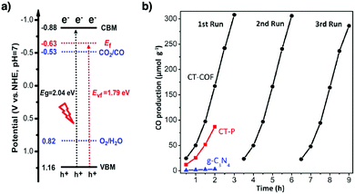 | ||
| Fig. 98 (a) Schematic band structure diagram of CT-COF. (b) Time courses of photocatalytic activity for CO production. Adapted with permission from ref. 509, Copyright 2020 Wiley-VCH. | ||
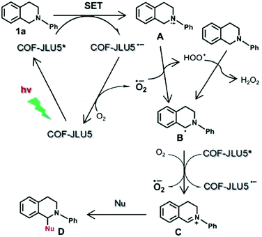 | ||
| Fig. 99 Proposed mechanism for the aerobic photocatalytic C–H functionalisation with COF-JLU5. Adapted with permission from ref. 178, Copyright 2017 RSC. | ||
Similarly, photocatalytic aerobic oxidation of secondary amines to imines has been developed by using Por-sp2c-COF (Fig. 21o) as a photocatalyst. Por-sp2c-COF possesses a fully sp2 carbon-conjugated backbone and enables enhanced electron delocalisation. Por-sp2c-COF catalyses the reaction of a range of secondary benzyl amines to produce the corresponding imines in a quantitative yield within 30 min under visible light at room temperature, while retaining a 97% yield after five cycles (Fig. 100).179 Photocatalytic oxidation of benzyl amine to imine has been performed with hydrazone-linked TFPT-BMTH COF (Fig. 96e). Interestingly, when the reaction is conducted in water, the imine product is hydrolysed to give the corresponding aldehyde, which then reacts with another benzyl amine in situ to form the corresponding oxidative coupling product. Under ambient conditions, the oxidative coupling reaction tolerates both electron-donating and electron-withdrawing substituents on the benzyl ring, with up to 99% conversion and recyclable six times without any noticeable decrease in conversion.514 LZU-190 (Fig. 96f) has been developed via cascade imine formation/cyclisation/oxidation to form benzoxazole linkages in the skeleton. The resulting LZU-190 is stable to withstand strong acids (trifluoroacetic acid, 9 M HCl), strong base (9 M NaOH) and boiling water and visible light for three days. LZU-190 catalyses the oxidative hydroxylation of a wide range of substituted arylboronic acids to phenols, including heteroarylboronic acids and even bulky polycyclic substrates, with up to 99% yields in the presence of oxygen (Fig. 101a). Notably, it retains high catalytic activity even after 20 cycles. In this reaction, LZU-190 serves as a photosensitiser and produces a superoxide anion that promotes the transformation of arylboronic acids (Fig. 101b). This research thus not only expands the scope of reactions for COF synthesis, but also emphasises the importance of structural robustness in achieving a stable and reusable photocatalyst.322 Very recently, another benzoxazole COF, BBO-COF (Fig. 96g), has been prepared by self-polycondensation of a difunctionalised monomer. Although BBO-COF demonstrates high stability, reactivity and recyclability as LZU-190 in the same oxidative hydroxylation reaction, its preparation is greatly simplified by reducing the screening number of reaction conditions required for optimisation.515
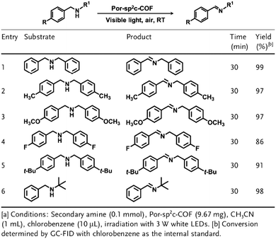 | ||
| Fig. 100 Photocatalytic oxidation of secondary amines to imines by Por-sp2c-COF. Adapted with permission from ref. 179, Copyright 2019 Wiley-VCH. | ||
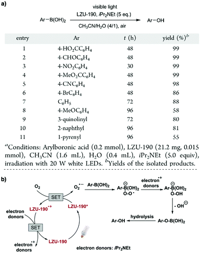 | ||
| Fig. 101 (a) Photocatalytic activity test of LZU-190 in oxidative hydroxylation of arylboronic acids to phenolsa. (b) Proposed mechanism for the photocatalytic transformation of arylboronic acids to phenols in the presence of LZU-190. SET stands for single-electron transfer. Adapted with permission from ref. 322, Copyright 2018 ACS. | ||
The superoxide anion promotes tandem radical reactions by activation of radical precursors. For example, hydrazone-linked 2D-COF-1 (Fig. 96h) has been developed as a heterogeneous photosensitiser for catalysing tandem addition of alkyl, aryl, trifluoromethyl, phosphorus-centred or sulphur-centred radicals to 2-aryl phenyl isocyanides, followed by cyclisation to yield a wide range of 6-substituted phenanthridines (Fig. 102). Due to its ideal π electronic structure and thermostability, this COF promotes reactions under ambient conditions, with unchanged activity of 92% yield after six cycles. Interestingly, it can be scaled up in a continuous flow system to gram scales with a 79% yield.516
 | ||
| Fig. 102 Visible-light-induced tandem radical addition–cyclisation of 2-aryl phenyl isocyanides. Adapted with permission from ref. 516, Copyright 2019 RSC. | ||
Electron deficient benzothiadiazole units are useful to reduce band gaps and to enhance charge separation by constructing donor–acceptor COFs. COF-JLU22 (Fig. 96j) with pyrene knots and benzothiadiazole linkers acts as the photosensitiser (Fig. 103) and catalyses photoreductive dehalogenation of a wide range of phenacyl bromides, with yields up to 88%, which are much higher than that of g-C3N4 (53% yield). As a photosensitiser, COF-JLU22 catalyses α-alkylation of aldehydes with α-brominated carbonyl groups with yields up to 93%. In both reactions, COF-JLU22 is recyclable five times.181 Another example is TPT-BT-COF (Fig. 96k), which is formed by condensing 1,3,5-triphenylbenzene knots with benzothiadiazole linkers. TPT-BT-COF catalyses photoreduction of toxic Cr(VI) ions to less toxic Cr(III) ions in water, in the absence of a sacrificial donor. Owing to its conduction band of −0.44 V (versus NHE) and a band gap of 2.05 eV, TPT-BT-COF achieves over 99% efficiency in 75 min upon visible light irradiation even after five cycles.182
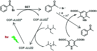 | ||
| Fig. 103 Proposed reaction mechanism for photoreductive dehalogenation reaction with COF-JLU22. Adapted with permission from ref. 181, Copyright 2019 RSC. | ||
In addition to photoredox reactions, COFs serve as photosensitisers to produce cis olefins via photoisomerisation of the corresponding trans isomers. Usually, high energy UV light or a homogeneous photosensitiser is necessary for trans-to-cis isomerisation. However, TpTt COF (Fig. 96l) allows the reaction to proceed in 90% yield under a blue LED in 18 h while retaining its catalytic activity after four cycles. The reaction initiates via the excitation of TpTt to the singlet excited state (S1) with visible light, followed by an intersystem crossing to the triplet excited state (T1), before transferring its energy to trans-stilbene. trans-Stilbene is then excited to form the biradical intermediate, before isomerisation to give cis-stilbene. The triazine knot enables π–π interaction with the trans isomer, whereas the β-ketoenamine is suggested to increase the lifetime of the triplet excited state of TpTt COF. These two effects work together to accelerate the photoisomerisation.517
11.2 Electrocatalysis
Developing efficient electrodes is the bottleneck of electrocatalysis for practical applications. Molecular electrocatalysts, such as porphyrins and phthalocyanines,518 have been developed as electrocatalysts but suffer from poor stability and cyclability.519,520 In contrast, inorganic heterogeneous electrocatalysts show high stability and recyclability, but it is difficult to tune their structures and to improve their activities. Ultimately, COFs combine the features of molecular and heterogeneous electrocatalysts. COFs allow precise tuning of electronic properties and can easily retain their structural integrity after repeated use. The extended π conjugation endows COFs with conductivity, which is a must for electrode materials. Moreover, their large surface area and well dispersed catalytic sites promote redox reactions. Combining all these features together in one material, COFs are regarded as next generation electrocatalysts.Pyrolysis of Co-COF (Fig. 104b) yields a Co/N/C hybrid with graphitic layers and homogeneously dispersed Co nanoparticles, which exhibits activity in oxygen reduction similar to commercial 20% Pt/C catalyst.188 By a similar approach, anchoring Co2+ and Fe2+ to TpBpy produces Fe,Co-COF (Fig. 104c), which upon pyrolysis yields a bimetallic porous carbon. The resulting carbon exhibits excellent activity to achieve a half-wave potential of 0.80 V, a current density of 6.08 mA cm−2 and a Tafel slope of 91 mV dec−1. In this case, Fe and Co assist the graphitisation and formation of a hierarchical porous structure, which facilitates ion transport. The uniformly distributed FeCo bimetallic nanoparticles provide abundant active sites for promoting the reduction reaction.191
Recently, silica nanoparticles have been developed as a template for the synthesis of TpBpy (Fig. 84b). The resulting SiO2@TpBpy, upon loading with Fe(III) ions and pyrolysis, removes the SiO2 and produces mC-TpBpy-Fe with a BET surface area of 362 m2 g−1, which is larger than that (38 m2 g−1) of a non-templated control. The mesoporosity improves the mass transfer and accessibility of the active sites. mC-TpBpy-Fe exhibits an onset potential of 0.92 V, a half-wave potential of 0.845 V and a current density of 5.92 mA cm−2. Interestingly, a Zn–air battery using mC-TpBpy-Fe on a carbon cloth electrode powers up a 2 V LED (Fig. 105a). The battery exhibits a peak power density of 81 mW cm−2, which is comparable with that of the Pt/C battery (77 mW cm−2) (Fig. 105b). mC-TpBpy-Fe exhibits higher discharge stability and tolerates a higher current density of 20 mA cm−2 (Fig. 105c). mC-TpBpy-Fe exhibits a capacity of 625 mA h gZn−1 at 20 mA cm−2 and maintains its efficiency after 4 cycles (Fig. 105d).192
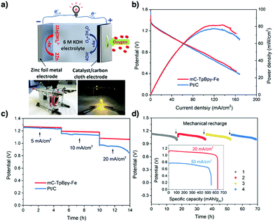 | ||
| Fig. 105 Performance of mC-TpBpy-Fe in a Zn–air battery. (a) Schematic diagram of a Zn–air battery and photographs of a lab-made Zn–air battery with zinc foil as an anode, mC-TpBpy-Fe loaded onto carbon cloth as a cathode (left) and a LED connected to two batteries (right). Comparison of (b) the polarisation and power density curves of primary Zn–air batteries using mC-TpBpy-Fe and Pt/C as ORR catalysts and (c) discharge curves of the primary Zn–air batteries using mC-TpBpy-Fe and Pt/C as ORR catalysts at various current densities. (d) Long-time durability of a primary Zn–air battery using mC-TpBpy-Fe at a current density of 20 mA cm−2. The battery is mechanically rechargeable; that is, the Zn foil and electrolyte were replaced at the time indicated by arrows. Inset: Specific capacities of the Zn–air batteries using mC-TpBpy-Fe normalised to the mass of the consumed Zn at various current densities (20 and 50 mA cm−2). Adapted with permission from ref. 192, Copyright 2019 ACS. | ||
In an attempt to exclude metal, an electrocatalyst derived from TPB-DMTA COF (Fig. 14l) has been explored by doping with phosphorus and pyrolysis. Due to the surface defects, enhanced conductivity and smaller charge transfer resistance, the resulting porous carbon exhibits a half-wave potential of 0.81 V, a current density of 5.7 mA cm−2 and a low Tafel slope of 72 mV dec−1.189
Although pyrolysis yields carbons with improved catalytic activities, poor control over the process usually results in a complete loss of important physical features such as surface area, porosity and active sites. In order to take advantage and retain the structural features of 2D COFs, a new strategy has to be developed. To combat this problem, we have explored a template approach for the pyrolysis of TAPT-DHTA-COF (Fig. 104d). Introducing phytic acid (PA) into the pores and layers of TAPT-DHTA-COF as a template guides the formation of 2D porous PA@TAPT-DHTA-COF1000 (Fig. 106). Upon pyrolysis, PA dopes the 2D carbon with abundant phosphorus atoms, greatly increasing the density of active sites. The resulting PA@TAPT-DHTA-COF1000 is further pyrolysed under an NH3 atmosphere to produce PA@TAPT-DHTA-COF1000NH3. In addition to its enhanced active sites, PA@TAPT-DHTA-COF1000NH3 has a BET surface area of 1160 m2 g−1 and hosts a hierarchical porous structure with small pore sizes of 0.5–0.6 nm that favours mass transport towards and from the catalytic sites. Moreover, its layered and nanosized 2D graphitic structure is retained, increasing the exposure of active sites for catalytic reactions. PA@TAPT-DHTA-COF1000NH3 exhibits exceptional performance to achieve an onset potential of 0 V, a half-wave potential of −0.11 V, a current density of 7.2 mA cm−2 and a Tafel slope of 110 mV dec−1, which are much superior to those of platinum and most carbon catalysts. Interestingly, PA@TAPT-DHTA-COF1000NH3 catalyses the oxygen evolution reaction, with a current density of −10 mA cm−2 at 0.97 V. Therefore, the template pyrolysis enables the preparation of porous carbon electrocatalysts and offers a way to designing electrocatalysts.190
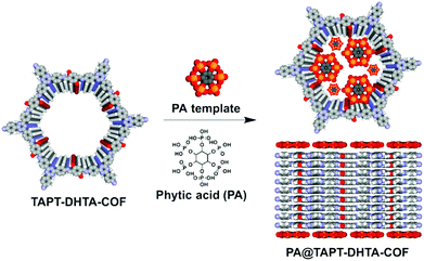 | ||
| Fig. 106 Template synthesis of PA@TAPT-DHTA-COF by mixing TAPT-DHTA-COF with PA. The PA molecules occupy the pores (upper for top view) and separate COFs by coating on the surface (lower for side view). Adapted with permission from ref. 190, Copyright 2018 Wiley-VCH. | ||
Traditionally, noble metal-based electrocatalysts such as RuO2 and IrO2 have shown remarkable performance with low overpotentials. However, their high cost and scarcity have greatly impeded their large-scale use, thereby underpinning the research into noble-metal-free electrocatalysts. These electrocatalysts usually consist of metal nanoparticles on conductive supports to compensate for their low activity and high overpotential. CoxNiy(OH)2 nanoparticles have been supported on nitrogen-rich IISERP-COF2 (Fig. 104e), where dense nitrogen atoms greatly increase interactions with the CoxNiy(OH)2 nanoparticles and fix them on IISERP-COF2. The small pores of IISERP-COF2 guide the growth of nanoparticles with sizes less than 2 nm, which are uniformly distributed across the COF. The resulting composite exhibits an overpotential of 258 mV, an onset potential of 1.43 V and a low Tafel slope of 38.9 mV dec−1 at a current density of 10 mA cm−2.193 Similarly, growing Ni3N nanoparticles onto benzimidazole-linked IISERP-COF3 (Fig. 104f) achieves an overpotential of 230 mV at a current density of 10 mA cm−2.194 Besides metal nanoparticles, coordination of metal ions offers another way to electrocatalytically active COFs. Anchoring Co2+ to TpBpy (Fig. 84b) produces Co-TpBpy, which shows an overpotential of 400 mV at a current density of 1 mA cm−2, a Tafel slope of 59 mV dec−1 and 94% activity retention after 1000 cycles.195
Porosity plays an important role in electrocatalysis. Usually, pyrolysis of COFs yields micropores and mesopores. Although small pores provide a large surface area for interactions with reactants, it hinders diffusion to and from the active sites. In this context, introducing macropores (pore sizes > 50 nm) to promote mass transport without sacrificing the surface area of COFs is a key. Similar to SiO2-templated synthesis,192 polystyrene spheres (PSs) have been used as a hard template during the synthesis of TpBpy (Fig. 84b) to introduce macropores into macro-TpBpy. Compared to TpBpy, macro-TpBpy has similar crystallinity, a higher BET surface area (723 vs. 588 m2 g−1) and a larger total pore volume (1.273 cm3 g−1vs. 0.381 cm3 g−1). The presence of macropores is evident from the N2 adsorption isotherms, which show a sharp increase in nitrogen uptake at high relative pressure. Coordination of Co2+ ions to macro-TpBpy produces macro-TpBpy-Co, which achieves an overpotential of 380 mV at a current density of 10 mA cm−2 and a low Tafel slope of 54 mV dec−1, which is superior to those of macro-TpBpy and TpBpy-Co. The improved activity originates from the hierarchical pore structures, which not only provide high surface area and easy access to catalytic centres but also allow oxygen to diffuse quickly.196
Recently, phenazine-linked COF-C4N (Fig. 104g) has been developed for exploring electrocatalysts. The abundant nitrogen atoms promote hole formation on adjacent carbons, which act as active sites for O2 evolution. COF-C4N achieves a low overpotential of 349 mV at a current density of 10 mA cm−2 and a Tafel slope of 64 mV dec−1. Notably, COF-C4N tolerates current densities up to 209 mA cm−2 owing to its stability and enhanced conductivity.524
![[thin space (1/6-em)]](https://www.rsc.org/images/entities/char_2009.gif) 000 (Fig. 107b),197 which is superior to those of rhenium-complexed COFs.237,525 It was also observed that thin films of COF-366-Co on a highly ordered pyrolytic graphite electrode increases the electrochemical accessibility of the active cobalt species. The resulting electrode exhibits a current density of 45 mA mg−1 cobalt and an FECO of 87%, which is a 9-fold improvement compared to bulk COF-366-Co powder. Integration of electron-withdrawing groups into COF-366-Co promotes the reduction of Co2+ to Co+, which improves its catalytic activity. COF-366-F-Co (Fig. 104i) with fluorine substituents exhibits the highest current density at 65 mA mg−1.198
000 (Fig. 107b),197 which is superior to those of rhenium-complexed COFs.237,525 It was also observed that thin films of COF-366-Co on a highly ordered pyrolytic graphite electrode increases the electrochemical accessibility of the active cobalt species. The resulting electrode exhibits a current density of 45 mA mg−1 cobalt and an FECO of 87%, which is a 9-fold improvement compared to bulk COF-366-Co powder. Integration of electron-withdrawing groups into COF-366-Co promotes the reduction of Co2+ to Co+, which improves its catalytic activity. COF-366-F-Co (Fig. 104i) with fluorine substituents exhibits the highest current density at 65 mA mg−1.198
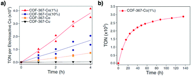 | ||
| Fig. 107 (a) Bulk electrolyses of bimetallic COFs at −0.67 V (versus RHE), showing TONs of carbon monoxide production by COF-367-Co(1%), COF-367-Co(10%), COF-367-Co and COF-367-Cu (TON with respect to the active copper porphyrin). Two separate experimental runs were conducted for each time point, with the line showing the average of the measurements. (b) Long-term bulk electrolysis of COF-367-Co(1%) at −0.67 V (versus RHE). Adapted with permission from ref. 197, Copyright 2015 AAAS. | ||
Motivated by the electron-donating ability of TTF units, TTF-Por(Co)-COF (Fig. 104j) has been designed to enhance the efficiency of electron transfer to the metalloporphyrin, which is the active site for CO2 reduction. Compared to COF-336-Co, TTF-Por(Co)-COF exhibits a higher faradaic efficiency (95% vs. 70.8%) at −0.7 V (vs. RHE) and partial current density (6.88 mA cm−2vs. 2.17 mA cm−2) at −0.9 V.526
In order to design a more renewable catalytic system, cobalt is replaced with more abundant iron. The resulting FeDhaTph-COF (Fig. 104k) on carbon cloth exhibits an average FECO of 80%, with a TOF of more than 600 h−1 mol−1 of electroactive Fe in acetonitrile or dimethylformamide.199 Amine-linked COF-300-AR (Fig. 104l) on a flat silver electrode tolerates highly acidic (6 M HCl) and basic (6 M NaOH) conditions. The electrode achieves FECOs of 53% and 80% at potentials of −0.70 and −0.85 V, respectively, which are higher than those (13% and 43%) of imine-linked COF-300. The improved activity originates from two effects: one is that COF-300-AR absorbs CO2 to form carbamate via the amine linkages, and the other is that, as the carbamate is in close proximity to the electrode surface, it accepts electrons directly from the silver electrode surface to convert into CO.527 This result uncovers the CO2 reduction mechanism and sheds light on the electrocatalytic CO2 reduction.
11.3 Catalytic carbon dioxide fixation
While photo- and electrocatalytic reductions of CO2 sequester anthropogenic CO2 by its conversion to valuable chemicals, they are facing low efficiency issues. From a synthetic point of view, catalytic conversion of CO2 directly to useful chemicals presents a more significant step towards CO2 sequestration. In fact, COFs catalyse the chemical fixation of CO2 by the ring opening of epoxides and nucleophilic addition of CO2 under ambient conditions. Given these points, a catalyst that is capable of activating epoxides and CO2 and stabilising negatively charged intermediates is highly desirable (refer to Section 2.5 Catalytic units).Integrating a CO2-philic nitrogen-rich triazine knot into COF-JLU7 (Fig. 79h) improves its catalytic performance. COF-JLU7 has a surface area of 1392 m2 g−1 and exhibits a CO2 uptake capacity of 151 mg g−1. Attributed to its ability to form interlayer hydrogen-bonding interactions with the incoming epoxide (Fig. 108a), COF-JLU7 catalyses the formation of cyclic carbonates to achieve 99% yield at 40 °C (Fig. 108b), without obvious decreases in yield and selectivity after five cycles.154
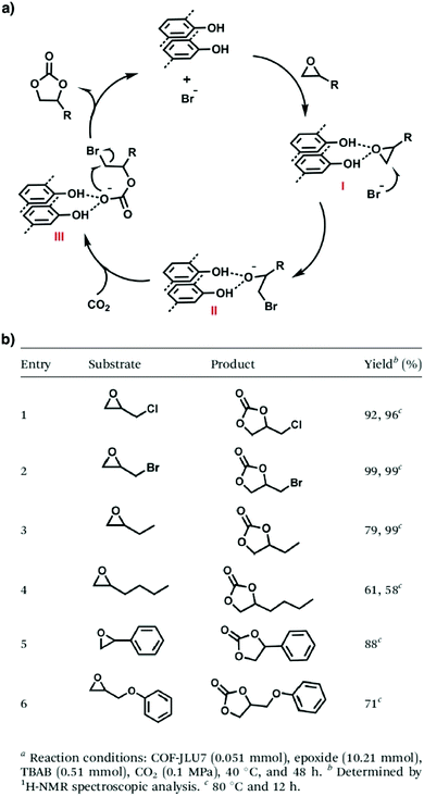 | ||
| Fig. 108 (a) A proposed reaction mechanism for the cycloaddition reaction of CO2 with epoxides catalysed by COF-JLU7 and TBAB. (b) Cycloaddition of CO2 with different substituted epoxides to form cyclic carbonates over COF-JLU7a. Adapted with permission from ref. 154, Copyright 2018 RSC. | ||
2,3-DhaTph COF (Fig. 104m) consists of a catechol linker, which acts as a hydrogen-bonding donor to interact with CO2 and epoxides and catalyses the cycloaddition of epoxides with CO2. 2,3-DhaTph COF enables the bulk reaction of CO2 with both aliphatic and aromatic epoxides at 110 °C to achieve up to 95% yields and to proceed cleanly to reach 99% selectivity. The catalyst also promotes the cycloaddition between CO2 and aziridines to produce oxazolidinones in up to 97% yield and with regioselectivities of more than 97/3 (Fig. 109). In addition to the hydrogen bonds provided by the catecholic groups, the catalytic activity of 2,3-DhaTph COF originates from its high surface area of 1019 m2 g−1 and dense active sites.153
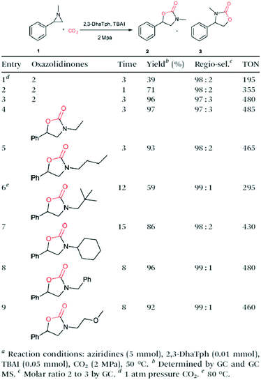 | ||
| Fig. 109 Synthesis of oxazolidinones using 2,3-DhaTph COF as a catalyst systema−e. Adapted with permission from ref. 153, Copyright 2016 RSC. | ||
Imidazolium-modified COF-IL (Fig. 104n) has been developed as a catalyst owing to the presence of the C2 hydrogen in imidazolium, which serves as a hydrogen-bonding donor to promote transformation. Notably, COF-IL is applicable to produce a broad range of substituted cyclic carbonates with nearly quantitative yields. In order to enhance the processability of COF-IL and simplify separation from the reaction mixture, COF-IL is covalently fixed to chitosan to form a COF-IL@chitosan composite via photoinduced thiol–ene reaction between the terminal alkene of COF-IL and thiol-functionalised chitosan. The resulting COF-IL@chitosan composite is moulded into a cuplike fixed bed reactor and fitted into a large reaction container (Fig. 110a–c). This system catalyses scaled-up reaction between CO2 and styrene oxide (175 mL), which is 10-fold higher in terms of the styrene oxide amount compared to COF-IL. COF-IL@chitosan achieves a 91% yield and retains 89% yield even after five cycles (Fig. 110d–f).155
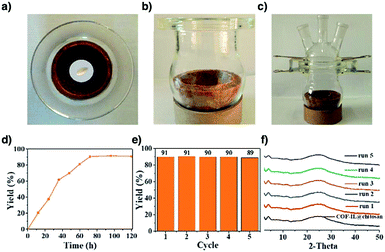 | ||
| Fig. 110 (a–c) Top and side photographic views of a cuplike COFIL@ chitosan aerogel reactor. (d) Reaction monitoring. Reaction conditions: styrene oxide (1.53 mol, 175 mL), CO2 (1 atm), aerogel (16.8 g, 1.5 mol% COF-IL equiv.), 80 °C, solvent free. (e) Catalytic cycles. After each run, the reaction solution was poured out and the cuplike aerogel was washed with acetone and dried in a vacuum. (f) Corresponding PXRD patterns of the cuplike aerogel reactor after each catalytic cycle. Adapted with permission from ref. 155, Copyright 2019 RSC. | ||
Another imidazolium-functionalised COF, COF-HNU3 (Fig. 104o), has been prepared via post-synthetic modification to have a BET surface area of 2027 m2 g−1. COF-HNU3 catalyses the cycloaddition of epoxides with CO2 efficiently to reach a 96% yield and a high TON of 495![[thin space (1/6-em)]](https://www.rsc.org/images/entities/char_2009.gif) 000. The high activity originates from its high crystallinity, dense active sites and facile transport of substrates and products. The C2 hydrogen of the imidazole ring can be deprotonated by Cs2CO3 to yield a N-heterocyclic carbene, which allows it to catalyse the reductive formylation of a range of phenylamines with CO2 to form formamides in 90% yield in 1 h.156 This is superior to tetraalkylammonium bromide decorated [Et4NBr]50%-Py-COF (Fig. 104p) in terms of catalyst loading (0.5 mol% versus 5 mol%) and reaction time (1 h versus 24 h).85
000. The high activity originates from its high crystallinity, dense active sites and facile transport of substrates and products. The C2 hydrogen of the imidazole ring can be deprotonated by Cs2CO3 to yield a N-heterocyclic carbene, which allows it to catalyse the reductive formylation of a range of phenylamines with CO2 to form formamides in 90% yield in 1 h.156 This is superior to tetraalkylammonium bromide decorated [Et4NBr]50%-Py-COF (Fig. 104p) in terms of catalyst loading (0.5 mol% versus 5 mol%) and reaction time (1 h versus 24 h).85
Zwitterionic [BE]50%-TD-COF (Fig. 111a) has been synthesised by anchoring betaine groups onto the pore walls via Williamson ether synthesis. Remarkably, [BE]50%-TD-COF serves as a divergent catalyst for the reductive transformation of CO2 in the presence of an amine and a phenylsilane. Depending on the reaction temperature, stoichiometry and CO2 pressure, a wide range of formamides, aminals and methylamines are produced in up to 90% yield and with over 99% selectivity (Fig. 112a). Mechanistic studies reveal that the carboxylate groups in [BE]50%-TD-COF activate the Si–H bond of phenylsilane for the CO2 insertion (Fig. 112b).229
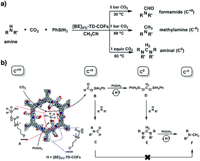 | ||
| Fig. 112 (a) Using [BE]X%-TD-COFs as catalysts for hierarchical reduction of CO2 with amines to afford formamides, aminals and methylamines. (b) Proposed reaction mechanism of hierarchical reduction of CO2 catalysed by [BE]X%-TD-COFs (H) with amines and PhSiH3 to gain formamides (C), aminals (E) and methylamines (F). Adapted with permission from ref. 229, Copyright 2018 ACS. | ||
In order to integrate two catalytic sites in a close proximity, phosphonium bromide decorated linear polymer (PPS) is grown in the 1D channels of TpBpy COF (Fig. 84b) to coordinate with Cu(II). PPS⊂COF-TpBpy-Cu retains the crystallinity of TpBpy COF but the BET surface area decreases from 1497 m2 g−1 for TpBpy COF to 496 m2 g−1. PPS⊂COF-TpBpy-Cu catalyses the cycloaddition of CO2 to a variety of epoxides, achieving up to 98% yields. PPS⊂COF-TpBpy-Cu is superior to a mixture of PPS and COF-TpBpy-Cu that exhibits only a 16% yield and a mixture of soluble phosphonium bromide (PPh3EtBr) and COF-TpBpy-Cu, which shows a 73% yield. The reactivity originates from a cooperative effect in which the Lewis acidic Cu(II) sites activate epoxides, while Br− anions on PPS open up epoxides for addition reaction with CO2 (Fig. 113). In this composite, the flexibility of PPS plays a role in improving access to its Br− active sites. PPS⊂COF-TpBpy-Cu is recyclable ten times. Notably, PPS⊂COF-TpBpy-Cu with only 5 mg transforms 10 g of epichlorohydrin to achieve a 95% yield.234 This work shows the excellent performance of cooperative catalysts and introduces a new way to the functionalisation of 1D channels of COFs.
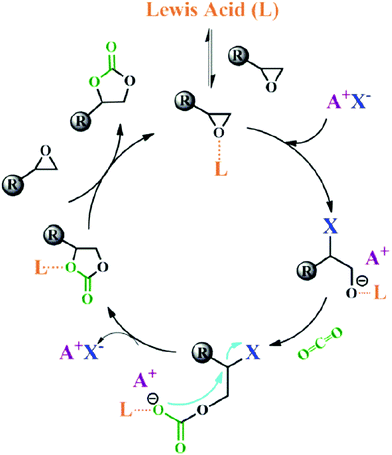 | ||
| Fig. 113 Proposed mechanism for the Lewis acid-catalyzed CO2 insertion into epoxides in the presence of halide anions. Adapted with permission from ref. 234, Copyright 2016 ACS. | ||
As one of the best activators of alkynes, silver catalysts have been used for different reactions.528 Incorporating Ag nanoparticles into COFs to produce heterogeneous catalysts allows the expensive silver to be recycled, which is important for prolonged cycling catalytic applications. Using TpPa-1 (Fig. 63e) as a support, Ag nanoparticles have been anchored to yield Ag@TpPa-1. Ag@TpPa-1 catalyses cycloaddition-rearrangement between CO2 and propargylic amine derivatives to form tetramic acids with up to 98% yield at 60 °C under 1 atm CO2 (Fig. 114).152 Likewise, Ag nanoparticles immobilised onto IISERP-COF15 (Fig. 111b) and 3D-HNU-5 (Fig. 79e) catalyse the cycloaddition between CO2 and propargylic alcohol derivatives to yield α-alkylidene cyclic carbonates with up to 97% and 99% yields, respectively. Both reactions proceed at room temperature under 1 atm CO2, without any significant decrease in yields after five cycles.246,529
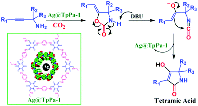 | ||
| Fig. 114 Production of tetramic acid from CO2 and primary derivatized propargylic amines. Adapted with permission from ref. 152, Copyright 2019 RSC. | ||
11.4 Organocatalysis
Homogeneous organocatalysis faces a challenge owing to the difficulty of isolating expensive catalysts for repeated use. Developing heterogeneous organocatalysts that are recoverable and reusable is the most promising strategy for addressing this key issue. Most heterogeneous organocatalysts have been developed using linear polymers as supports. However, these organocatalysts show limited activities owing to the low accessibility of active sites. We have explored COFs for designing heterogeneous organocatalysts that are superior in activity compared to monomeric organocatalysts while retaining their stereoselectivity and diastereoselectivity.The squaramide unit serves as both a hydrogen-bonding donor and acceptor, making it an attractive organocatalytic moiety. Incorporating squaramide units to form COF-SQ (Fig. 111c) spatially disperses the squaramide units across the material, thereby preventing their self-aggregation. COF-SQ catalyses the Michael addition reaction between substituted β-nitroolefins and 1,3-dicarbonyl compounds with up to 98% yield under mild conditions (Fig. 115) while enabling four cycles without obvious degradation.530
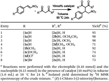 | ||
| Fig. 115 Michael addition reaction of various nucleophiles and electrophilesa−c. Adapted with permission from ref. 530, Copyright 2019 RSC. | ||
In order to establish a stable imine-linked COF platform for designing heterogeneous organocatalysts, we have developed an extremely stable COF, TPB-DMTP-COF. Based on this stable skeleton, we have developed a series of mesoporous hexagonal organocatalysts.
A series of tetragonal porphyrin [Pyr]X-H2P-COFs (Fig. 31g, X = 0, 25, 50, 75 and 100) have been developed by appending different densities of chiral pyrrolidine onto the pore walls via pore surface engineering to develop a three-component synthetic scheme followed by click reaction. Integrating chiral pyrrolidine units transforms an achiral COF into a chiral COF. The resulting chiral [Pyr]X-H2P-COFs exhibit enantioselectivities (ee's) of 44–51% in catalysing an asymmetric Michael addition reaction between trans-4-chloro-β-nitrostyrene and propanal, which is similar to that of (49%) molecular pyrrolidine control. [Pyr]25-H2P-COF achieves 100% conversion in 1 h to reach a diastereoselectivity (dr) of 70/30, which are much superior to those (3 h and 60/40) of the molecular catalyst (Fig. 116a). Distinct from the molecular catalyst, [Pyr]25-H2P-COF is recyclable at least four times. Notably, the catalyst is applicable to a wide range of substrates, giving similar ee and dr values. Remarkably, [Pyr]25-H2P-COF serves as a catalytic bed in an open column to construct a continuous flow reactor. At a flow rate of 18 μL min−1, the reactor enables a full conversion with constant 44% ee and 65/35 dr over 48 h (Fig. 116b).157
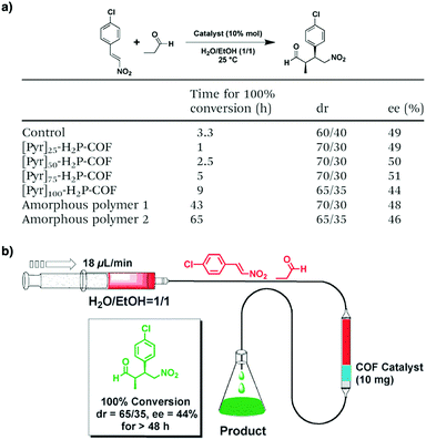 | ||
| Fig. 116 (a) Comparison of the pyrrolidine control, amorphous nonporous polymers and COFs as catalysts for a Michael addition reaction. (b) Representative chart for the flow reaction system based on the organocatalytic COF column. Adapted with permission from ref. 157, Copyright 2014 RSC. | ||
[(S)-Py]X-TPB-DMTP-COFs (Fig. 31h, X = 0.17, 0.34 and 0.5) by integrating chiral organocatalytic pyrrolidine units onto the pore walls via pore surface engineering to employ a three-component polycondensation system in conjunction with click reaction. Different from other imine-linked COFs, [(S)-Py]X-TPB-DMTP-COFs exhibit high stability under strongly acidic (12 M HCl), basic (14 M NaOH) and aqueous (boiling water) conditions for one week, originating from strong interlayer interactions via the integration of methoxy groups on the linker sites.
In this series, [(S)-Py]0.17-TPB-DMTP-COF exhibits a remarkable catalytic activity in catalysing the asymmetric Michael addition between cyclohexanone and substituted β-nitrostyrenes in water under ambient conditions, to achieve a full conversion in 12 h, which is much shorter than that (22 h) of the homogeneous S-pyrrolidine molecular catalyst. This originates from the concentration effect of the 1D channels of COFs, which accumulates reactants from the water phase in the pores. [(S)-Py]0.17-TPB-DMTP-COF achieves 92% ee and 90/10 dr, which are similar to those (96% ee, 91/9 dr) of the molecular catalyst. Specifically, dense catalytic sites on the pore walls cause steric hindrance to the catalytic sites, which trigger a slow reaction while retaining the ee and dr values. This result suggests that the local interface has to be considered for the design of catalytic sites (Fig. 117a). Notably, [(S)-Py]0.17-TPB-DMTP-COF is applicable to a diversity of different reactants and substrates, showcasing a broad scope of heterogeneous organocatalysts (Fig. 117b). [(S)-Py]0.17-TPB-DMTP-COF enables separation from the reaction mixtures by centrifugation, while rinsing with THF regenerates the catalyst for repeated uses. Indeed, [(S)-Py]0.17-TPB-DMTP-COF retains the ee and dr values after five cycles.158 One important point is that the three-component strategy for introducing chiral catalytic sites via a post-synthetic click reaction under mild conditions enables the reservation of chiral sites. This is in contrast to other chiral COFs, which are synthesised by polycondensation under solvothermal conditions at elevated temperatures. This strategy thus offers a platform for designing heterogeneous catalysts to combine stability, activity, enantioselectivity, diastereoselectivity and recyclability in one material.
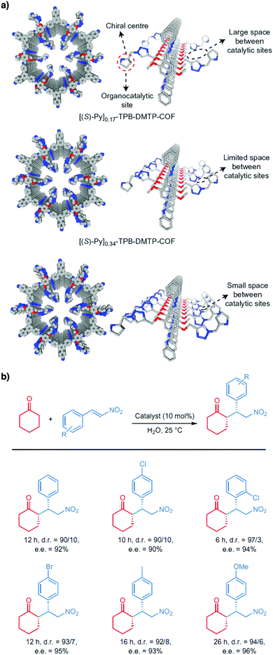 | ||
| Fig. 117 (a) Channel-wall structures of chiral organocatalytic COFs. (b) Scope of reactants. Adapted with permission from ref. 158, Copyright 2015 Springer Nature. | ||
Direct integration of chiral catalytic sites into COFs via solvothermal conditions has been developed for a series of organocatalysts, while the retentivity of chirality remains unclear. For example, an ortho-phenylenediamine precursor upon transformation into a benzimidazole unit installs a chiral pyrrolidine moiety, which serves as a linker for the synthesis of LZU-76 (Fig. 111d) under solvothermal conditions. LZU-76 catalyses the asymmetric aldol reaction between aryl aldehydes and acetone to achieve 84% yield and 88% ee. Although a long reaction time of 18–96 h is required compared to its homogeneous counterpart (6 h), LZU-76 is recyclable three times while retaining its enantioselectivity.159
Similarly, reaction of eight aldehydes of the 2-substituted-1H-benzo[d]imidazole backbone with TAPB knots enables the pore surface engineering of hexagonal CCOFs with eight different chiral sites on the imidazole rings (Fig. 118a). Specifically, these chiral COFs host different hydrogen-bonding sites as well as nitrogen-containing functional groups, including secondary amines, tertiary amines, and guanidines, and exhibit different catalytic performances towards asymmetric amination of β-ketoesters (Fig. 118b). In particular, TAH-CCOF2 (Fig. 111e) exhibits the highest activity and enantioselectivity in catalysing the asymmetric amination of ethyl 2-oxocyclopentane-1-carboxylate with di-tert-butylazodicarboxylate to achieve 96% yield and 99% ee in dichloromethane at −78 °C. This performance stems from the local interface in which dense N–H units form hydrogen bonds with reactants and the spatial bulkiness induces stereodiscrimination, so that the reactivity and enantioselectivity are simultaneously enhanced. TAH-CCOF2 is applicable to a variety of substrates and is recyclable seven times.160
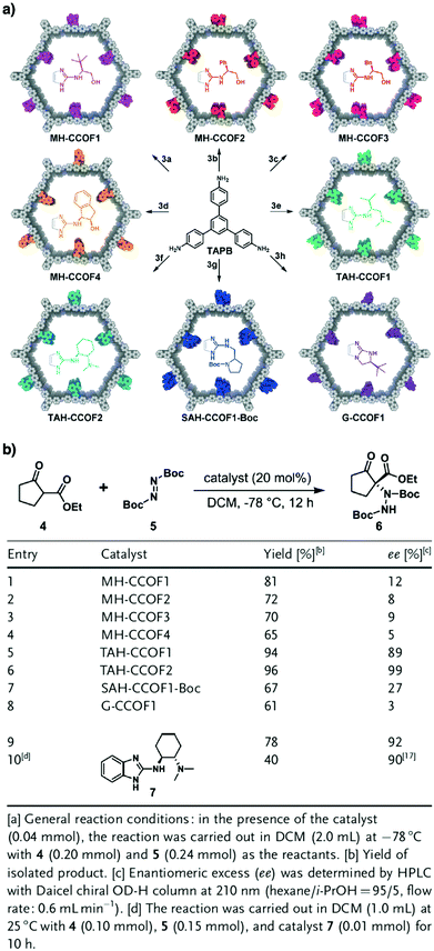 | ||
| Fig. 118 (a) Divergent synthesis of chiral COFs by imine formation. (b) Systematic screening of CCOF catalysts in asymmetric amination of β-ketoesters.a Adapted with permission from ref. 160, Copyright 2019 Wiley-VCH. | ||
Apart from linkers, chiral knots have been developed for the preparation of chiral COFs. Integrating chiral pyrrolidine and imidazoline moieties into a triphenylbenzene core forms chiral knots, which upon polycondensation produce chiral DMTA-TPB1/n′ COFs (Fig. 111f). These chiral COFs tolerate various substrates and catalyse different types of asymmetric transformations, including α-aminooxylation to achieve 77% yield and 95% ee, aldol reaction to reach 95% yield, 92% ee and 9/1 dr and the Diels–Alder reaction to attain 85% yield, 95% ee and 22![[thin space (1/6-em)]](https://www.rsc.org/images/entities/char_2009.gif) :
:![[thin space (1/6-em)]](https://www.rsc.org/images/entities/char_2009.gif) 1 dr and are cyclable at least five times.161 Recently, chiral dihydropyrroloimidazole (DHIP) and pyrrolidine units have been introduced into COFs via direct polymerization of chiral triphenylbenzene knots. DHIP-containing TPB2-COF (Fig. 111g) facilitates asymmetric Steglich rearrangement to reach 95% yield and 84% ee, while pyrrolidine-containing Tfp2-COF (Fig. 111h) promotes the asymmetric Michael addition to achieve 95% yield, 86% ee and 17/1 dr. Interestingly, both catalysts promote reactions under mild conditions with a catalyst loading content of 10 mol% in solvents such as water and ethanol and are cyclable five times.162
1 dr and are cyclable at least five times.161 Recently, chiral dihydropyrroloimidazole (DHIP) and pyrrolidine units have been introduced into COFs via direct polymerization of chiral triphenylbenzene knots. DHIP-containing TPB2-COF (Fig. 111g) facilitates asymmetric Steglich rearrangement to reach 95% yield and 84% ee, while pyrrolidine-containing Tfp2-COF (Fig. 111h) promotes the asymmetric Michael addition to achieve 95% yield, 86% ee and 17/1 dr. Interestingly, both catalysts promote reactions under mild conditions with a catalyst loading content of 10 mol% in solvents such as water and ethanol and are cyclable five times.162
Very recently, proline polymers have been integrated into the channels of TpBD COF (Fig. 63f). The resulting chiral composite catalyses asymmetric aldol reaction between substituted aryl aldehydes and cyclopentanone or cyclohexanone to achieve up to 99% conversion, 99% ee and 96/4 dr.532
Other than functioning as direct catalysts in organic transformations, COFs have recently been developed as phase-transfer catalysts. By integrating crown ether-containing linker units, a series of COFs with secondary rings of different sizes have been prepared. Amongst them, 18C6-COF (Fig. 111i) accommodates K+ ions in its cavity, allowing I− counterions to be activated. Indeed, 18C6-COF exhibits a remarkable activity as a phase transfer catalyst in the Halex reaction, where it performs almost equally (96% yield) as the best commercially available catalyst (tetrabutylammonium bromide). Most importantly, 18C6-COF is recyclable to retain a 95% yield in the fifth cycle (Fig. 119a). 18C6-COF serves as a phase transfer catalyst in a diversity of nucleophilic substitution reactions, tolerating different substrates as well as nucleophiles (Fig. 119b).531
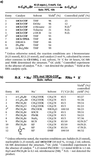 | ||
| Fig. 119 (a) Phase transfer catalytic activity test of 18C6-COF in the iodination of 1-bromooctane under solid–liquid–solid conditionsa. (b) Catalytic activity test of 18C6-COF in different nucleophilic substitutionsa. Adapted with permission from ref. 531, Copyright 2020 RSC. | ||
11.5 Diels–Alder reactions
COFs constitute aligned π arrays to form sequenced C–H sites extruded from the pore walls, which are accessible to external guests for promoting reactions. Imine-linked Py-An COF (Fig. 26c) with anthracene π arrays has been developed to form dense aromatic C–H bonds on the 1D channel walls. Notably, Py-An COF catalyses the Diels–Alder reaction between 9-hydroxymethylanthracene and N-substituted maleimide in water and ethanol. Remarkably, Py-An COF achieves up to 99% yield even after four cycles under ambient conditions. The activity of Py-An COF arises from the C–H⋯π interactions between C–H units of anthracene linkers and the π face of 9-hydroxymethylanthracene (Fig. 120), which not only increases the concentration of 9-hydroxymethylanthracene in the pores but also aligns it into an appropriate orientation for the Diels–Alder reaction. Indeed, the concentration of 9-hydroxymethylanthracene increases by more than 50-fold in the pores of Py-An COF.350 Thus, exploration of π-electronic walls offers a strategy for designing catalysts.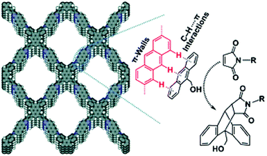 | ||
| Fig. 120 C–H⋯π interactions between C–H units of anthracene linkers and the π face of 9-hydroxymethylanthracene. Adapted with permission from ref. 350, Copyright 2015 RSC. | ||
C![[double bond, length as m-dash]](https://www.rsc.org/images/entities/char_e001.gif) C bond linked COF-701 (Fig. 15f), formed via aldol condensation of 2,4,6-trimethyl-1,3,5-triazine and 4,4′-biphenyldicarbaldehyde, has a stable sp2-carbon framework and confines BF3 in the pores. The resulting BF3⊂COF-701 catalyses the Diels–Alder reaction between dimethylbutadiene and benzoquinone in 8 h at 25 °C with a yield of 88%, which is low compared to that (99%) of BF3·OEt2.310
C bond linked COF-701 (Fig. 15f), formed via aldol condensation of 2,4,6-trimethyl-1,3,5-triazine and 4,4′-biphenyldicarbaldehyde, has a stable sp2-carbon framework and confines BF3 in the pores. The resulting BF3⊂COF-701 catalyses the Diels–Alder reaction between dimethylbutadiene and benzoquinone in 8 h at 25 °C with a yield of 88%, which is low compared to that (99%) of BF3·OEt2.310
11.6 Knoevenagel reactions
2D imine-linked COFs contain aromatic imine nitrogen atoms, which are weak in basicity to catalyse reactions. Integration of amide linkages increases the basicity of COFs, which enables promotion of the Knoevenagel reaction. Specifically, TABTA-COF-1 and TABTA-COF-2 (Fig. 111j and k) with pre-installed amide linkages catalyse the reaction between a few aromatic aldehydes and malononitrile to achieve up to 99% yield.533 In order to increase basicity, 3D BF-COF-2 (Fig. 111l) has been synthesised with an alkyl amine, i.e. 1,3,5,7-tetraaminoadamantane. With microporous cavities (7.7 × 10.5 Å2), BF-COF-2 traps benzaldehyde and malononitrile and serves as a base to catalyse the Knoevenagel reaction to achieve 98% conversion in benzene at room temperature in 10 h. Almost no reaction takes place for large substrates, suggesting size selectivity.293 Along this research direction, two 3D COFs, i.e. DL-COF-1 and DL-COF-2 (Fig. 111m), containing both acidic boroxine and basic imine linkages have been developed. DL-COF-1 and DL-COF-2 serve as catalysts to promote cascade acetal deprotection and Knoevenagel reactions to achieve over 90% yield.534 This result demonstrates that introduction of two different linkages not only increases the structural diversity and complexity but also brings about cascade catalytic systems.Combining acidic catechol and basic imine sites in one framework, 2,3-DhaTph COF (Fig. 104m) acts as a bifunctional catalyst to promote a one-pot deprotection–Knoevenagel condensation between benzaldehyde dimethylacetal and malononitrile to achieve 80% yield.535
11.7 Metal complex catalysis
COFs enable the integration of various coordination sites via different approaches to form covalently linked metal complexes, enabling the design of local interfaces of the metal complexes. The d orbitals of metal ions introduce new routes into the substrate activation and acceleration pathway, such as complexation, oxidative addition, olefin insertion and β-hydride elimination. Different from homogeneous metal complex catalysts, which are hardly recyclable, anchoring metal complexes to COFs endows them with recoverability and recyclability, minimising undesirable environmental impacts.The imine linkage, owing to the presence of the nitrogen atom, forms complexes with Pd(II) ions. Imine-linked COF-LZU1 (Fig. 121a) forms Pd/COF-LZU1 upon complexation with Pd(II). At a catalyst loading of 0.5 mol%, Pd/COF-LZU1 catalyses the Suzuki–Miyaura coupling reaction between substituted aryl bromides or iodides and phenylboronic acid to achieve up to 98% yield within 4 h in p-xylene at 150 °C. Decreasing the loading to 0.1 mol% gives identical yields but requires a long reaction time of 5 h (Fig. 122). Pd/COF-LZU1 is cyclable four times with a gradual decrease of crystallinity.130 A similar COF, Pd/H2P-Bph-COF (Fig. 121b), catalyses the Suzuki–Miyaura coupling reaction at 110 °C in toluene in 1.5 h.131 On the other hand, 3D Pd(OAc)2@COF-300 (Fig. 121c) promotes the reaction to completion in a methanolic aqueous solution at 70 °C in 20 min and is applicable to a broad range of substrates, including polyaromatics and aromatic heterocycles.133 The triazine Pd/TATAE COF (Fig. 121d) promotes the coupling reaction in water at room temperature and tolerates a wide range of substrates with up to 98% yield in 2 h.132
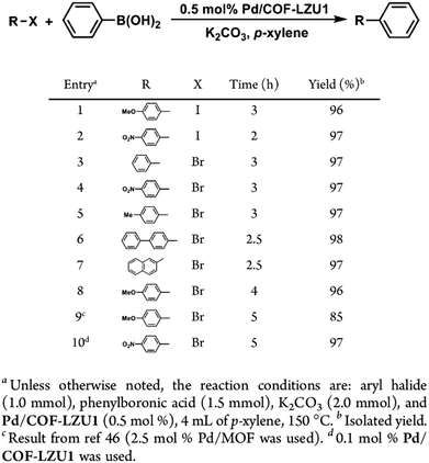 | ||
| Fig. 122 Catalytic activity test of Pd/COF-LZU1 in the Suzuki–Miyaura coupling reaction. Adapted with permission from ref. 130, Copyright 2011 ACS. | ||
Recently, an imine-linked COF with N-heterocyclic carbene (NHC) linkers enables bonding with Pd(II) to form Pd@COF-NHC (Fig. 121e). It catalyses the Suzuki–Miyaura coupling reaction in water at room temperature in 1 h. Notably, Pd@COF-NHC promotes the reaction with a wide range of substrates almost quantitatively (Fig. 123) and is recyclable eight times.134
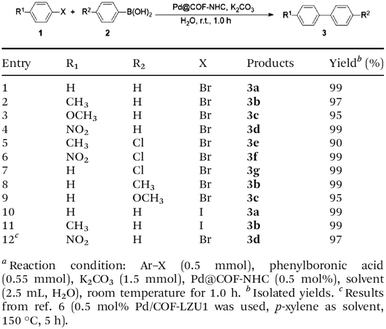 | ||
| Fig. 123 Suzuki–Miyaura cross coupling of aryl halides with different boronic acids.a–c Adapted with permission from ref. 134, Copyright 2019 RSC. | ||
COFs with Pd complexes have been developed to catalyse other C–C bond formation reactions including the Heck reaction,133 the Sonogashira reaction,133 aryl halide–triaryl-bismuth coupling,134 conjugate addition,536 cyanation,537 silane oxidation-Hiyama coupling239 and alcohol oxidation-Knoevenagel condensation.242
Although the Suzuki–Miyaura coupling reaction can be promoted by Pd-incorporated COFs at room temperature132,134 in an alcoholic or aqueous solution,132–134 C–N coupling reaction remains a challenging goal. Among various methods such as Buchwald–Hartwig coupling, Petasis coupling and Ullmann coupling, Chan–Lam coupling has been extensively studied. Although various copper-based homogeneous and heterogeneous catalysts have been developed,538 there is a general lack of catalytic systems that combine efficiency, cost and sustainability. Cu@PI-COF (Fig. 121f) has been developed to promote the Chan–Lam coupling reaction by addressing these issues. Cu@PI-COF is prepared by mechanical grinding of monomers followed by uptake of Cu(II) in ethanol at room temperature.
Cu@PI-COF catalyses the Chan–Lam coupling reaction between a wide range of arylboronic acids and substituted anilines, tolerating various electron-donating groups including methyl, methoxy and ethoxy, and electron-withdrawing groups such as halogenated, trifluoromethyl, nitro and bulky tert-butyl groups. Cu@PI-COF maintains efficiency for primary and secondary alkyl amines, allyl amines, aromatic heterocycle-substituted amines (pyridines, furans, carbazoles and benzothiazoles) and aromatic heterocyclic amines (indazoles and imidazoles). Across 78 reactions, most systems achieve over 80% yield at room temperature in methanol or water in 8 h. After the reaction, Cu@PI-COF is recyclable eight times and can be easily regenerated by washing with methanol and drying. Cu@PI-COF enables scale-up to 20 mmol while retaining a 92% yield.136 The combination of its simple preparation method, mild reaction conditions, wide scope of substrates and recyclability makes Cu@PI-COF an attractive heterogeneous catalyst for the Chan–Lam coupling reaction.
Using four nitrogen and oxygen atoms in the two neighbouring layers of imine-linked TAPT-DHTA-COF to coordinate with Cu(II) produces Cu-COF (Fig. 121g). It catalyses olefin oxidation to aldehydes or ketones with tert-butyl hydroperoxide (TBHP) to achieve conversions up to 98% in 5 h in acetonitrile at 40 °C.135
Besides copper, other first-row transition metal complexes have been incorporated into COFs for designing heterogeneous catalysts. Nickel can be post-synthetically complexed to the cavities in dehydrobenzoannulene (DBA) knots of DBA-2D-COF to yield Ni-DBA-2D-COF (Fig. 121h). In the presence of the reducing agent dimethylethylsilane, Ni-DBA-2D-COF catalyses the reductive cleavage of aryl C–S bonds with a wide range of substrates, to achieve yields between 2% and 87% (Fig. 124). Despite its relatively lower yield, it is superior or comparable to other Ni-based homogeneous catalysts. Most importantly, unlike the homogeneous analogue Ni-DBA[12], Ni-DBA-2D-COF is recyclable at least five times, without compromising its performance.31 Coordination of Mn(II) to anionic COF produces [SO3Mn]-DhaTab (Fig. 121i), which upon addition of bipyridine forms [Mn(bpy)2]-DhaTab (Fig. 121i). Both COFs catalyse the aerobic epoxidation of olefins in acetonitrile at room temperature with up to 99% yield, while [Mn(bpy)2]-DhaTab enables a higher reaction rate.539 Phenazine-linked Mn/PZ-COF-2 (Fig. 121j) has been prepared by one-pot oxidation-condensation of hexahydroxy triphenylene and 1,2,4,5-tetraminobenzene, followed by complexation with Mn(II). Mn/PZ-COF-2 catalyses the cyanosilylation of aryl aldehydes at room temperature in 8 h to reach almost quantitative yields.137 This is much superior to the β-ketoenamine-based hydrazone-linked Co(II)-incorporated NUS-50-Co and NUS-51-Co COFs.540
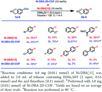 | ||
| Fig. 124 Catalytic performances of Ni-DBA[12]a and Ni-DBA-2D-COFb for the reductive cleavage of aryl C–S bonds. Adapted with permission from ref. 31, Copyright 2020 ACS. | ||
Incorporating early transition metal complexes such as V(IV)![[double bond, length as m-dash]](https://www.rsc.org/images/entities/char_e001.gif) O species into COFs enables the design of catalysts. Integrating VO(acac)2 into catechol-containing TAPT-2,3-DHTA COF yields VO-TAPT-2,3-DHTA COF (Fig. 121k), which is capable of catalysing three different reactions. VO-TAPT-2,3-DHTA COF catalyses the Prins reaction between β-pinene and paraformaldehyde with a 69% yield in 12 h in acetonitrile at 80 °C (Fig. 125a). It also promotes the oxidation of a range of sulphides to sulphoxides with up to 96% yield in 4 h in acetonitrile at 25 °C (Fig. 125b). Moreover, it facilitates the Mannich-type reaction between substituted phenols or β-naphthols and sulphides with up to 99% yield within 24 h in dichloromethane at 40 °C. For these three reactions, VO-TAPT-2,3-DHTA COF is recyclable up to five times while retaining its catalytic activities.138,139
O species into COFs enables the design of catalysts. Integrating VO(acac)2 into catechol-containing TAPT-2,3-DHTA COF yields VO-TAPT-2,3-DHTA COF (Fig. 121k), which is capable of catalysing three different reactions. VO-TAPT-2,3-DHTA COF catalyses the Prins reaction between β-pinene and paraformaldehyde with a 69% yield in 12 h in acetonitrile at 80 °C (Fig. 125a). It also promotes the oxidation of a range of sulphides to sulphoxides with up to 96% yield in 4 h in acetonitrile at 25 °C (Fig. 125b). Moreover, it facilitates the Mannich-type reaction between substituted phenols or β-naphthols and sulphides with up to 99% yield within 24 h in dichloromethane at 40 °C. For these three reactions, VO-TAPT-2,3-DHTA COF is recyclable up to five times while retaining its catalytic activities.138,139
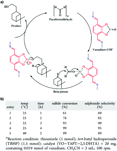 | ||
| Fig. 125 (a) Plausible mechanism of the Prins reaction catalysed by VO-TAPT-2,3-DHTA COF. (b) Oxidation of thioanisole into sulphoxide under different conditionsa. Adapted with permission from ref. 138, Copyright 2019 ACS. | ||
Ti(IV) complexes with alkoxy ligands exhibit Lewis acidity and activate carbonyl compounds for a range of nucleophilic addition reactions, while modification with chiral alkoxy ligands such as tetraaryl-1,3-dioxolane-4,5-dimethanols (TADDOL) offers high enantioselectivity for these transformations.541 TADDOL units have been integrated into CCOF-1 (Fig. 121l) and CCOF-2 (Fig. 121m) as chiral knots. Upon complexation with Ti(IV), both COFs exhibit activities in the asymmetric addition of diethylzinc to aromatic aldehydes with up to 99% conversion and 94% ee. Although comparable performance is achieved for the control homogeneous catalyst, its recyclability offers a way for versatile catalytic applications.140
Salen, an established tetradentate ligand, has the flexibility and stability to accommodate a wide range of metal ions in a square planar geometry for the design of catalysts.542 Salen COFs have been prepared by direct co-condensation of salicylaldehyde and ethylenediamine, which prevents the formation of unstable intermediates. Unlike salen that decomposes at pH 1, Salen-COFs are stable over a wide pH range from 1 to 14. Most importantly, Salen-COFs coordinate a wide diversity of metal ions, such as Cu(II), Ni(II), Zn(II), Co(II) and Mn(III), to produce the corresponding M/Salen-COFs (Fig. 121n). Co/Salen-COF catalyses the Henry reaction between aryl aldehydes and nitromethane to achieve yields up to 86% in 2–7 days in dichloromethane or methanol, between −30 °C and room temperature. Co/salen-COF can be cycled five times with a loss of yield from 86% to 67%.141
Following this strategy, a series of COF-salen-M (Fig. 121o) with metals Cu(II), Zn(II), Co(II), Co(III) and Mn(III) have been prepared. These COFs promote various reactions: COF-salen-Co(II) catalyses epichlorohydrin hydration, COF-salen-Mn(III) catalyses styrene epoxidation, and COF-salen-M (M = Co(II), Zn(II), Cu(II), Mn(III)) promote CO2 cycloaddition.142 The 3D salphen JUC-509 COF (Fig. 121p) coordinates with Mn(III), Cu(II) and Eu(II) ions to form JUC-509-M COFs, which show antioxidant activity to superoxide radical anions.144
Chiral salen COFs have been developed by using chiral salens as building blocks. Chiral CCOF 4-M (Fig. 121q) has been prepared via a similar route to COF-salen-M (Fig. 121o) by using chiral 1,2-diaminocyclohexane instead of ethylenediamine. CCOF 4 can be coordinated with different metals such as Zn(II), Fe(III), Co(II), V(IV), Mn(III), and Cr(III) or incorporated into bimetallic frameworks including Cr(III)/Mn(III), Cr(III)/Fe(III) and Cr(III)/Co(II). Remarkably, chiral CCOF 4-M catalyses a diversity of asymmetric reactions including cyanosilylation (CCOF 4-V), Diels–Alder (CCOF 4-Co), epoxidation (CCOF 4-Fe and CCOF 4-Mn), aminolysis of epoxides (CCOF 4-Cr) and aminohydroxylation of alkenes (CCOF 4-Cr-Mn) (Fig. 126). These reactions proceed with over 71% conversion and over 77% ee and can be recycled five times.143
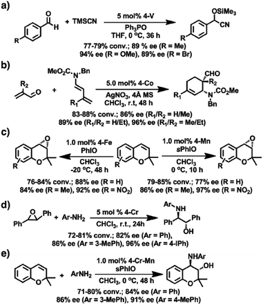 | ||
| Fig. 126 Asymmetric reactions catalysed by CCOFs: (a) cyanosilylation, (b) Diels–Alder, (c) epoxidation, (d) aminolysis of epoxides and (e) aminohydroxylation. Adapted with permission from ref. 143, Copyright 2017 ACS. | ||
Imine-linked bipyridine COFs have been developed for designing bimetallic COFs. Mn/Pd@Py-2,2′-BPyPh-COF (Fig. 121r) is prepared by sequential coordination with Mn(II) and Pd(II), in which Mn(II) coordinates with the intralayer bipyridine sites, while Pd(II) coordinates with the interlayer imine sites. Mn/Pd@Py-2,2′-BPyPh-COF catalyses the Heck-epoxidation tandem reaction between iodobenzene and styrene in 94% yield.145 Another bimetallic COF, RhI/PdII@75% BPy COF (Fig. 121s), promotes one-pot addition–oxidation between phenylboronic acid and benzaldehyde to achieve a 90% yield.146
Metalloporphyrins are typical metal complexes for catalysts. Using metalloporphyrins as building blocks enables the construction of catalytic COFs. For example, an iron(III) porphyrin COF (Fe-COF) (Fig. 121t) has been prepared to catalyse oxidation reaction, with H2O2 as the oxidant, to mimic peroxidase functions. The oxidation is confirmed by the colour change from colourless 3,3′,5,5′-tetramethylbenzidine (TMB) to blue oxTMB. Fe-COF exhibits an affinity with H2O2 and TMB and is stable over a wide range of pH values from 3 to 9 at different temperatures from 25 to 55 °C, which is much superior to horseradish peroxidase. Fe-COF is coupled to glucose oxidase to develop a one-pot colorimetric assay for the quantification of glucose in human serum samples (Fig. 127a). The assay achieves almost equal accuracy to commercial glucometers (Fig. 127b).543
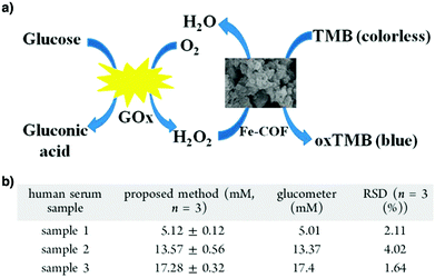 | ||
| Fig. 127 (a) Schematic representation of a colorimetric sensor for glucose detection using Fe-COF as the catalyst. (b) Determination of glucose in real samples according to the proposed approach. Adapted with permission from ref. 543, Copyright 2018 ACS. | ||
11.8 Metal nanoparticle catalysis
COFs constituted ordered pores with predesignable pore sizes, shapes and environments. This unique feature endows COFs with well-defined nanochannels for confining metal nanoparticles to explore various catalytic reactions.COFs have been developed for loading Pd nanoparticles. For example, TpPa-1 in the presence of Pd(II) (Fig. 63e) upon reduction with NaBH4 forms Pd(0)@TpPa-1, in which the Pd nanoparticles are stabilised by coordination from imine nitrogen and their sizes range from 4 nm to 10 nm. Pd(0)@TpPa-1 facilitates the Sonogashira reaction between aryl iodides and phenyl acetylenes in methanol at 105 °C to achieve a 94% yield in 6 h without copper(I) co-catalyst. Pd(0)@TpPa-1 also promotes the Heck reaction between aryl iodides and olefins with up to 95% yield under the same conditions. Although showing decreased activities after the first cycle, Pd(0)@TpPa-1 is superior to commercially available Pd/C.148
Instead of mixing Pd(II) complexes with COFs, coordinating Pd(II) to the bipyridine unit of TpBpy COF (Fig. 84b) followed by reduction yields Pd@TpBpy COF in which Pd nanoparticles are in situ generated. In this case, the Pd nanoparticles have sizes of 8–16 nm. Pd@TpBpy COF catalyses tandem Sonogashira/5-endo-dig cyclisation between substituted 2-bromophenols and phenyl acetylenes to yield a series of benzofurans in dimethylformamide at 150 °C with up to 80% yield (Fig. 128).147 These two examples suggest that Pd nanoparticles are majorly located on the surfaces of COFs or between layers, other than within the pores. This results from a weak interaction between COF walls and Pd nanoparticles. In order to reinforce the interactions with Pd nanoparticles, thioether-functionalised Thio-COF (Fig. 129a) with a pore size of 2.4 nm has been developed. Owing to the dense and strong sulphide ligands on the pore walls, Thio-COF enables nucleation and growth of Pd nanoparticles inside the pores, achieving precise control of nanoparticle size. Moreover, the Pd nanoparticles are isolated in the pores so that aggregation is largely prevented. As a result, Thio-COF creates Pd nanoparticles (PdNPs) with an average size of 1.78 nm that are evenly and densely dispersed within the pores. Interestingly, PdNPs@Thio-COF is highly efficient as only 0.1 mol% is sufficient to catalyse the Suzuki–Miyaura reaction between aryl bromides or iodides and phenylboronic acid. Notably, the reaction is complete in 3 h quantitatively at a relatively low temperature of 50 °C (Fig. 130).
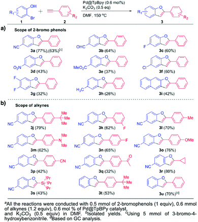 | ||
| Fig. 128 (a and b) Evaluation of the substrate scope. Adapted with permission from ref. 147, Copyright 2017 ACS. | ||
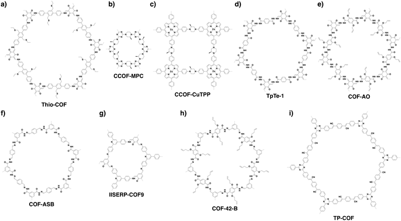 | ||
| Fig. 129 Structures of COFs developed for (a–g) metal nanoparticle catalysts and (h and i) enzyme hybrid catalysts. | ||
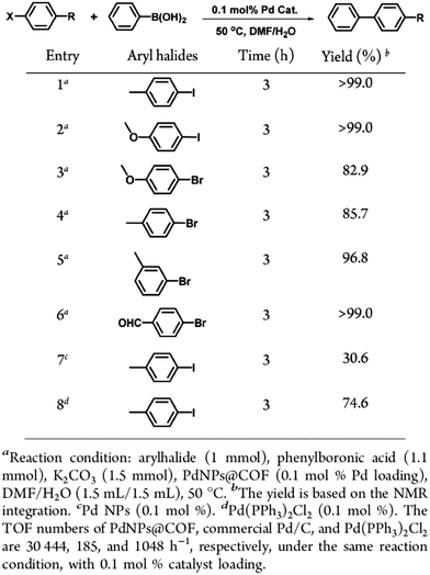 | ||
| Fig. 130 Catalytic performance of PdNPs@COF in the Suzuki–Miyaura coupling reaction. Adapted with permission from ref. 149, Copyright 2017 ACS. | ||
Different from other examples with gradual deactivation,147,148,544 PdNPs@COF is recycled five times with negligible loss of activity from >99% yield to 98% yield. With the same method, 1.7 nm-sized Pt nanoparticles (PtNPs) have been encapsulated in Thio-COF to produce PtNPs@Thio-COF. These studies offer a promising strategy for preparing highly dispersed ultrafine metal nanoparticles within the pores of COFs to construct catalytic systems.149
In addition to the direct use of thioether-functionalised monomers, post-synthetic thiol–ene click reaction has been used to install thioether and thiol groups to give COF-S-SH (Fig. 84l). Attributed to the small pore size (2.8 nm) and strong binding provided by the sulphur-rich chains, COF-S-SH allows the growth of ultrafine Au nanoparticles with sizes of 1.6–2.0 nm. Interestingly, the resulting Au@COF can be coated onto filter paper (Fig. 131a) and integrated into a continuous flow purification system (Fig. 131b). In addition to its removal of Rhodamine B dye, the filter paper can be reused after light irradiation at ≥420 nm for 30 min.38 Triphenyl phosphine is one of the most common ligands for various catalytic applications, owing to its broad compatibility with various metals as well as a strong binding. However, its incorporation into COFs has been largely unexplored. Recently, with PPh3-based knots, Phos-COF-1 (Fig. 21i) has been prepared. Phos-COF-1 has a pore size of 1.56 nm and allows the fine growth of various nanoparticles such as Pd NPs (1.62 ± 0.37 nm), Pt NPs (2.06 ± 0.54 nm), Au NPs (1.78 ± 0.32 nm) and PdAu NPs (1.03 ± 0.07 nm). These NPs@Phos-COF-1 catalyse a wide variety of reactions such as Suzuki–Miyaura coupling (PdNPs@Phos-COF-1), 4-nitrophenol reduction (PtNPs@Phos-COF-1), 1-bromo-4-nitrobenzene reduction (AuNPs@Phos-COF-1) and tandem Suzuki coupling-reduction (PdAuNPs@Phos-COF-1). Most reactions proceed with high efficiency (80% to >99% yields) in 2 h.36
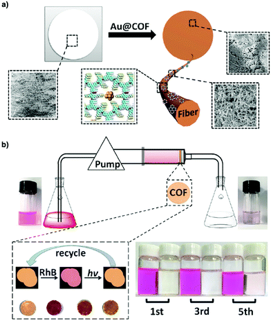 | ||
| Fig. 131 Diagrams of (a) the filter paper model and (b) the filter device. Adapted with permission from ref. 38, Copyright 2020 Wiley-VCH. | ||
Immobilisation of metal nanoparticles onto chiral COFs provides a way to promoting asymmetric reactions. For example, integration of the S-(+)-2-methylpiperazine linker induces homochirality of CCOF-MPC (Fig. 129b), which upon Pd(II) coordination and reduction forms homochiral Pd@CCOF-MPC, with Pd nanoparticles of sizes between 2 and 5 nm. Pd@CCOF-MPC catalyses an asymmetric Henry reaction between aryl aldehydes and nitromethane and asymmetric reductive Heck coupling between aryl halides and 2-cyclohexen-1-one, to achieve up to 99% yield and 97% ee. Notably, both reactions proceed under mild conditions in ethanol or ethanol/water and is recyclable at least five times with only a 6% decrease in yield and a 4% decrease in enantioselectivity.545 The chiral S-(+)-2-methylpiperazine linker is condensed with the copper tetrabromophenolphthalein (Cu-TBrPP) knot to produce homochiral CCOF-CuTPP (Fig. 129c), which yields Pd@CCOF-CuTPP with Pd nanoparticle sizes of 2–5 nm. Pd@CCOF-CuTPP catalyses the asymmetric multicomponent A3-coupling reaction between aryl aldehydes, phenyl acetylenes and secondary amines with up to 98% yield and 98% ee. Up to 91% yield and 92% ee are recorded after five cycles. Interestingly, owing to the photothermal function of Cu-TBrPP, the reaction can be promoted either at room temperature under visible light irradiation (>400 nm) or by heating to 58 °C in the dark. Similarly, immobilisation of Au nanoparticles produces Au@CCOF-CuTPP, in which the Au nanoparticles have a mean width and length of 3 and 30 nm, respectively. Au@CCOF-CuTPP catalyses the asymmetric Henry reaction between benzyl alcohols and nitromethane with up to 99% yield and 98% enantioselectivity.546
Being able to activate carbon–halogen bonds, Pd loaded COFs are promising as dechlorination catalysts for removing toxic aryl chlorides in water. However, the poor processability of COFs impedes their applications. To address this issue, Pd-loaded TpTe-1 (Fig. 129d) has been mixed with chitosan to yield Pd@TpTe-1@chitosan aerogel. The resulting composite dechlorinates a variety of aryl chlorides with over 93% yields in 1.5 h. Pd@TpTe-1@chitosan is processed into a U-shape monolith for use in a continuous flow system while retaining its activity without leaching Pd nanoparticles (Fig. 132). Similarly, an allyl-functionalised COF (COF-AO) (Fig. 129e) upon a thiol–ene click reaction with thiol-functionalised polysiloxane forms a composite membrane in which Pd nanoparticles are stabilised by the sulphur sites. The membrane exhibits activities similar to the Pd@TpTe-1@chitosan aerogel, where it is integrated into a continuous flow setup. Both composites are recyclable five cycles and promote the reaction at room temperature in water.150,151 These results suggest that mixing COFs with other polymers to enhance processability is promising for environmental applications.
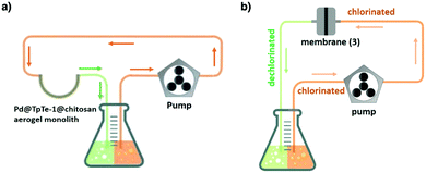 | ||
| Fig. 132 Continuous-flow setup for the continuous catalytic dehalogenation operation containing (a) a Pd@TpTe-1@chitosan aerogel monolith and (b) a Pd@COF-AO-based membrane. Adapted with permissions from ref. 150 and 151, Copyright 2018 RSC and ACS. | ||
Ru nanoparticles have been impregnated into COF-ASB (Fig. 129f) to produce Ru@COF-ASB by encapsulating Ru nanoparticles (2–5 nm) into COF-ASB. The resulting Ru@COF-ASB catalyses a solvent-free cascade aerobic oxidation of benzylic alcohols and subsequent imination with benzyl or phenyl amines to produce imine compounds with up to 92% yield in 22 h at 80 °C. Ru@COF-ASB is recyclable five times.548 Cu and Cu2O nanoparticles have been supported on IISERP-COF9 (Fig. 129g) to yield Cu@IISERP-COF9 and Cu2O@IISERP-COF9, respectively. Cu@IISERP-COF9 and Cu2O@IISERP-COF9 catalyse the Glaser–Hay coupling reaction between two alkynes. Compared to homogeneous Cu catalysts which predominantly yield homo-coupled products, Cu@IISERP-COF9 is highly selective to produce the hetero-coupled unsymmetrical 1,3-diyne with an average yield of 70%. The hetero-coupling activity originates from a combination of effects from the hydroxyl, pyridyl and pore environment (Fig. 133). Cu@IISERP-COF9 is recyclable five times without loss of activity and leaching.547
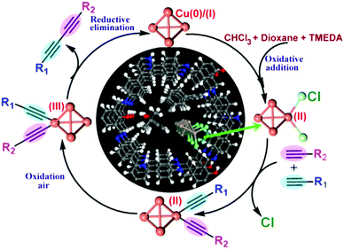 | ||
| Fig. 133 Mechanism of the heterocoupling reaction at the copper cluster surface. Adapted with permission from ref. 547, Copyright 2019 ACS. | ||
11.9 Enzyme–COF hybrid catalysis
COFs with well-defined pores are capable of loading enzymes to constitute heterogeneous enzymes. Typically, isolated enzymes are neither stable nor cyclable for prolonged or repetitive use. Although trapping enzymes in porous hosts is a routine approach to form heterogeneous enzyme catalysts, there is a general lack of host materials that combine strong enough host–enzyme interactions with loading efficiency.Amano lipase PS enzyme has been infiltrated into COF-OMe (Fig. 14l; = TPB-DMTP-COF)158 to form lipase@COF-OMe. Lipase@COF-OMe improves both the physical and chemical properties of the enzyme. Lipase@COF-OMe completes the kinetic resolution of racemic 1-phenylethanol with vinyl acetate to achieve over 49% yield within 30 min, which is much superior to that of the free enzyme (29% yield, 15 h). It tolerates organic solvents such as acetonitrile and achieves a 45% yield compared to 0% yield for the free enzyme. Moreover, lipase@COF-OMe tolerates a wide range of temperatures of up to 120 °C to achieve only a 30% decrease in activity, while the free enzyme is completely denatured (Fig. 134a). Compared to the free enzyme that shows a 60% decrease of activity in the second run, lipase@COF-OMe is recyclable at least six times without any decrease in yield or enantioselectivity (Fig. 134b). Notably, lipase@COF-OMe enables a scale-up synthesis (1-phenylenethanol; 2.0 g) to attain a 48% yield. The enhanced enzyme activity originates from the favourable hydrophobic interactions between the pore wall of COF-OMe and lipase PS, which promotes the infiltration of lipase PS and offers a stable local environment to shield the enzyme from deactivation.549 Together with the skeleton stability, COFs offer a way to confining enzymes by designing the appropriate pore size, shape and environment.550
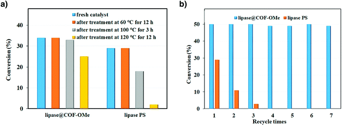 | ||
| Fig. 134 (a) Enzymatic activity assays in the kinetic resolution of 1-phenylethanol with vinyl acetate at different temperatures. (b) Recycling tests of lipase@COF-OMe and free lipase PS. Adapted with permission from ref. 550, Copyright 2018 ACS. | ||
Other than immobilisation of enzymes in the pores of COFs, encapsulation of enzymes in COF cages offers an approach to protect larger enzymes from environmental fluctuations. However, due to the harsh nature of COF formation, in situ encapsulation of enzymes is challenging. To circumvent this problem, a sacrificial template approach has been developed. Using bovine serum albumin (BSA) as a model to trap in MOF ZIF-90 yields BSA@ZIF-90. In this case, ZIF-90 acts as both a protective shell for BSA and a template for COF synthesis. Subsequently, the free aldehyde groups on BSA@ZIF-90 act as anchors to enable the formation of COF-42-B (Fig. 129h) and to produce BSA@ZIF-90@COF-42-B. Finally, ZIF-90 is hydrolysed and removed using mildly acidic (pH = 5) phosphate buffer solution to afford BSA@COF-42-B (Fig. 135a). To test the generality of this method, various combinations of different MOFs (ZPF-2, ZIF-8), COFs (COF-43-B) and other enzymes including catalase (CAT) and glucose oxidase (GOx) have been examined, where a wide tolerance is achieved. In particular, CAT@COF-42-B exhibits higher Kobs (0.0743 s−1) than CAT@ZPF-2 (0.0473 s−1), as well as higher activity than CAT@ZPF-2 and CAT in different chemical environments (Fig. 135b). The higher reactivity of the enzyme encapsulated in the COF is largely attributed to the higher degree of conformational freedom, as well as better mass transport across the porous network, compared to that in the MOF. Furthermore, CAT@COF-42-B is recyclable at least 10 cycles without noticeable compromise in activity (Fig. 135c). In order to expand the scope, GOx and CAT have been co-encapsulated into COF-42-B to allow the cascade oxidation of glucose and subsequent decomposition of H2O2 to water (Fig. 135d). Co-encapsulation of GOx and Hemin is possible, where the conversion is monitored by spectroscopic changes of TMB (Fig. 135e).551
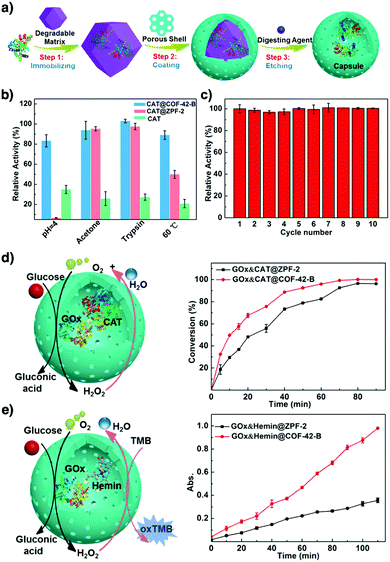 | ||
| Fig. 135 (a) Stepwise approach to construct biomacromolecule@capsule. (b) Activity percentages of CAT, CAT@ ZPF-2 and CAT@COF-42-B after treatment under various harsh conditions. (c) Recycling experiments of CAT@COF-42-B. (d) GOx, CAT@ZPF-2, GOx and CAT@COF-42-B activities based on the kinetic consumption of glucose. (e) GOx, Hemin@ZPF-2, GOx and Hemin@COF-42-B activities using a colorimetric assay. Adapted with permission from ref. 551, Copyright 2020 ACS. | ||
Owing to their extended conjugation, sp2 carbon-conjugated COFs have small band gaps and are attractive as light-harvesting antennae to transfer electrons for promoting reactions. For example, TP-COF (Fig. 129i) harvests visible light and enables photo-induced electron transfer to transform α-ketoglutarate into L-glutamate when coupled to L-glutamate dehydrogenase (Fig. 136). In the presence of electron mediator [Cp*Rh(bpy)(H)]+, the system produces L-glutamate in 97% yield within 12 min, which is much superior to those of organic and inorganic systems. This result shows the possibility of COFs for coupling with enzymes to construct artificial photosynthetic systems.552
 | ||
| Fig. 136 Illustration of the artificial PSI-induced coenzyme regeneration and photoenzymatic synthesis of L-glutamate by L-glutamate dehydrogenase (GDH). Adapted with permission from ref. 552, Copyright 2019 Wiley-VCH. | ||
12. Mass transport
Mass transport plays a key role in various applications, including separation, purification, fuel cells and rechargeable batteries. 2D materials such as graphene oxide (GO) or 1D materials such as carbon nanotubes suffer from their undesignable nature, which makes them unsuitable for many given applications.553 Tailorable MOFs have been explored for mass transport. However, they have stability issues under harsh transporting conditions.554 The ordered 1D channels found in COFs that are open and straight offer ideal pathways for transporting molecules and ions. Importantly, the predesignable pore topology, size and environment enable tailor-made design of pore interfaces for controlling interactions with molecules and ions and controlling their transporting functions (Scheme 10).12.1 Proton transport
Proton conducting materials are attracting increasing attention owing to their irreplaceable roles in fuel cells and other electronic devices. Owing to the uniqueness of 1D channels, COFs offer a platform for designing proton-conducting materials, as COFs are chemically stable and enable the loading of different proton carriers into the pores to constitute proton networks in the 1D nanochannels. Therefore, designing stable skeletons and high pore volumes are two key aspects in designing proton-conducting COFs.COFs for proton conduction can be categorised into two different classes: one is under anhydrous conditions (in the absence of water) and the other is proton conduction at different relative humidities. Water forms extended hydrogen-bonding networks which promote proton transport via hopping and usually works at a low temperature below 100 °C. On the other hand, proton conduction under anhydrous conditions requires more harsh conditions and the stability of COFs becomes critical. Proton carriers that allow anhydrous proton conduction are typically organic heterocyclic compounds or pure phosphoric acid other than water. These proton carriers enable proton transport at temperatures between 100 and 180 °C, but usually result in a low conductivity compared to water systems. Exploring COFs to combine stability and anhydrous proton conductivity in one material is still a challenging goal.
COFs have been developed for proton conduction under various humidity conditions below 100 °C. NUS-10(R) (Fig. 137a) with two sulphonyl groups at linker sites exhibits a proton conductivity of 3.96 × 10⁻² S cm−1 at 25 °C, with long-term stability at ambient temperature and 97% RH. In this case, the presence of water molecules plays an important role in increasing the proton conductivity as water functions as an external proton carrier to promote proton conduction across the water hydrogen-bonding network. Mixing NUS-10(R) with non-conductive polyvinylidene (PVDF) yields NUS-10(R)@PVDF-50, which exhibits a conductivity of 1.58 × 10⁻² S cm−1 at 80 °C in water. The Ea value is 0.21 eV, suggesting a proton hopping mechanism.318 By loading p-toluene sulphonic acid (PTSA) as a proton carrier, the resulting PTSA@Tp-Azo (Fig. 137b), PTSA@TpBpy (Fig. 84b) and PTSA@TpBD(Me)2 (Fig. 84o) with PTSA contents of 12, 10 and 8 wt% exhibit proton conductivities of 5.3 × 10⁻², 6.2 × 10⁻² and 7.8 × 10⁻² S cm−1, respectively, at 80 °C and 95% RH.555 Aza-fused π-conjugated aza-COF-1 and aza-COF-2 (Fig. 137c and d) have been developed by integrating phenanthroline linkers to form hydrogen-bonding interactions with H3PO4 to construct proton-conducting materials with 3.7 and 4.6 wt% H3PO4 loading contents, respectively. Aza-COF-1 and aza-COF-2 exhibit proton conductivities of 1.23 × 10⁻³ and 4.80 × 10⁻³ S cm−1 at 50 °C and 97% RH, respectively.556
Charged COFs have been developed for proton conduction. For example, cationic EB-COF:Br with Br− counteranions (Fig. 34d) can load polyoxometalate (PW12O403−) anions via ion exchange to form EB-COF:PW12.372 EB-COF:PW12 exhibits a proton conductivity of 3.32 × 10⁻⁴ S cm−1 using water as a proton carrier at 25 °C and 97% RH. In contrast, EB-COF:Br shows a proton conductivity of 2.82 × 10⁻⁶ S cm−1 under otherwise the same conditions. This suggests that water forms hydrogen-bonding networks in the pores and the hydrophilic PW12O403− anions interconnect the networks, improving the proton conductivity (Fig. 138). Ionic COF-1-Li and COF-1-Na have been developed by lithiation and sodiation of neutral COF-1, respectively. The pristine COF-1 has a negligible ionic conductivity. In contrast, COF-1-Li and COF-1-Na (Fig. 137e) exhibit proton conductivities of 2.7 × 10⁻² and 2.5 × 10⁻² S cm−1 at 40 °C and 98% RH, respectively. The ion–dipole interaction between alkali metal ions enhances the water sorption ability and the hydrogen bond density, greatly promoting the proton conductivities. COF-1-Li, together with the gel precursor, pyrrole and phosphoric acid, is gelled into a membrane with an optimised proton conductivity of 1.3 × 10⁻¹ S cm−1 at 40 °C and 98% RH.557 Polybenzimidazoles have been extensively investigated as robust supports for proton conduction. A benzimidazole-linked COF (BIP COF) (Fig. 14q) has been developed to achieve a proton conductivity of 3.2 × 10⁻² S cm−1 at 95 °C and 95% RH.300 The Ea value is 0.31 eV, suggesting a hopping mechanism.
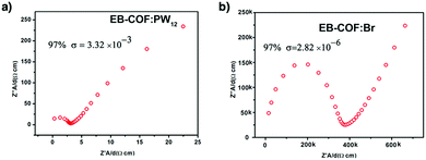 | ||
| Fig. 138 Proton conductivities of (a) EB-COF:PW12 and (b) EB-COF:Br at 97% RH. Adapted with permission from ref. 372, Copyright 2016 ACS. | ||
Mixing COFs with other materials enables the preparation of membranes for proton conduction: for example, COF(TfBD)@Nafion/GO and COF(TpBD)@Nafion/GO, in which COF nanofibers (Fig. 63f and 137f) act as shortcuts for fast proton transport, GO serves as the support and sulphonate-terminated Nafion acts as the proton source.558 COF(TfBD)@Nafion/GO achieves a conductivity of 0.30 S cm−1 at 80 °C and 95% RH. This conductivity is more than 2-fold those of Nafion (0.13 S cm−1) and fibrous COF(TpBD) (0.13 S cm−1). As Nafion itself allows for an extremely high proton conduction and GO may cause electrical conductivity, the nature and origin of the conductivity of the membranes remain to be clarified. Recently, a family of COFs, i.e. NKCOF-1, NKCOF-2, NKCOF-3 and NKCOF-4 (Fig. 139a–d), have been developed via a stepwise approach to bear hydrogen-bonding acceptors and donors.277 In these COFs, the azo sites with nitrogen atoms serve as hydrogen-bonding acceptors to dock H3PO4, while phenol units produce protons. The skeleton hydrophilicity induces water adsorption and facilitates proton transport. Loading H3PO4 into NKCOF-1, NKCOF-2, NKCOF-3 and NKCOF-4 generates H3PO4@NKCOF-1, H3PO4@NKCOF-2, H3PO4@NKCOF-3 and H3PO4@NKCOF-4 with H3PO4 contents of 8.1, 2.0, 4.7 and 4.0 wt%, respectively. H3PO4@NKCOF-1, H3PO4@NKCOF-2, H3PO4@NKCOF-3 and H3PO4@NKCOF-4 exhibit proton conductivities of 1.13 × 10⁻¹, 4.28 × 10⁻², 1.12 × 10⁻² and 7.71 × 10⁻² S cm−1, respectively, at 80 °C and 98% RH. H3PO4@NKCOFs have been fabricated into solid electrolyte membranes for proton exchange. In this series, H3PO4@NKCOF-1 achieves a current density of 456 mA cm−2 and a power density of 81 mW cm−2 (Fig. 140).277 Nevertheless, H3PO4@NKCOFs do not show proton conductivities under anhydrous conditions.
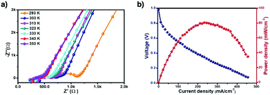 | ||
| Fig. 140 (a) Nyquist plots of H3PO4@NKCOF-1 measured at 98% RH at different temperatures. (b) Fuel cell polarisation (navy) and power density (red) curves of H3PO4@NKCOF-1 measured at 60 °C using single H2/O2 cell assembly at 100% RH. Adapted with permission from ref. 277, Copyright 2020 Wiley-VCH. | ||
As scrutinised above, although H3PO4 is used as a proton carrier, its proton conduction in COFs is still low even under high RH conditions and the working temperature is usually below 100 °C.
We have developed a series of stable COFs for anhydrous proton conduction using organic heterocycles and neat phosphoric acid as proton carriers. TPB-DMTP-COF (Fig. 14l) is a mesoporous COF with an extremely stable skeleton and has a pore size of 3.26 nm and a pore volume of 1.34 cm3 g−1. TPB-DMTP-COF enables loading of proton carriers such as imidazole (im) and triazole (trz) with a high content of 155 wt% and 180 wt%, respectively, to form im@TPB-DMTP-COF and trz@TPB-DMTP-COF. Imidazoles and triazoles are organic heterocycles which enable anhydrous proton conduction at temperatures above 100 °C.282 trz@TPB-DMTP-COF and im@TPB-DMTP-COF exhibit proton conductivities of 1.1 × 10⁻³ and 4.37 × 10⁻³ S cm−1 at 130 °C. Deuterated imidazole reduces the proton conductivity to 1.84 × 10⁻³ S cm−1, suggesting that the conductivity originates from protons. The Ea value of im@TPB-DMTP-COF is 0.38 eV, suggesting that protons hop across the 1D channels via the hydrogen-bonding network of imidazoles (Fig. 141). Notably, the proton conductivity is two orders of magnitude higher than that of MOFs with imidazoles as proton carriers. This work reveals that the 1D mesopores are crucial to proton conduction; they allow high loading contents of proton carriers and provide pathways for proton transport.
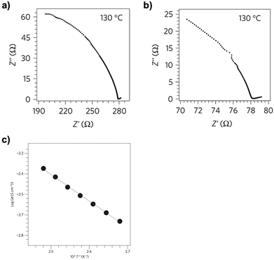 | ||
| Fig. 141 Nyquist plots of (a) trz@TPB-DMTP-COF and (b) im@TPB-DMTP-COF. (c) Temperature dependence of the proton conductivity of im@TPB-DMTP-COF. Black dots are experimental data; blue lines are curve-fitting results. Adapted with permission from ref. 282, Copyright 2016 Springer Nature. | ||
Imine-linked Tp-Azo, owing to the interactions between the hydrogen-bond accepting nitrogen atoms of the azo units and the protons of H3PO4 carriers in the pores, enables loading of H3PO4 to form PA@Tp-Azo (Fig. 137b) with a H3PO4 content of 5.4 wt%. PA@Tp-Azo shows an anhydrous proton conductivity of 6.7 × 10⁻⁵ S cm−1 at 67 °C, which is higher than that (9.9 × 10⁻⁵ S cm−1) of PA@Tp-Stb (Fig. 139e) without the azo group.315
Imine-linked TpBpy-ST (Fig. 84b) enables the loading of H3PO4 to form H3PO4@TpBpy-ST in which the bipyridine linker interacts with H3PO4via hydrogen-bonding interactions. H3PO4@TpBpy-ST exhibits an anhydrous proton conductivity of 1.98 × 10⁻³ S cm−1 at 120 °C and shows a low Ea value of 0.12 eV.316 TpPa-SO3H COF (Fig. 139f) with sulphonic acid on the pore walls exhibits an anhydrous intrinsic proton conductivity of 1.7 × 10⁻⁵ S cm−1 at 120 °C without loading proton carriers. Loading phytic acid as a proton carrier into the pores produces phytic@TpPa-(SO3H-Py) (Fig. 139g) with a phytic acid content of 24 wt%. It exhibits an anhydrous conductivity of 5 × 10⁻⁴ S cm−1 at 120 °C with an Ea value of 0.16 eV (Fig. 142).317 In this case, the sulphonic acid groups serve as intrinsic proton-conducting sites, while the pyridine units immobilise phytic acid via hydrogen-bonding interactions, which enable extrinsic conduction, thereby improving proton conduction.
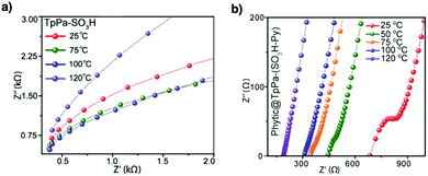 | ||
| Fig. 142 The proton conductivities with Nyquist plots under anhydrous conditions at different temperatures of (a) TpPa-SO3H and (b) phytic@TpPa-(SO3H-Py). Adapted with permission from ref. 317, Copyright 2016 ACS. | ||
Very recently, imine-linked TPB-DMeTP-COF (Fig. 139h) has been developed as a dually stable porous skeleton that enables anhydrous proton super flow, with an exceptional rate that is improved by 2–8 orders of magnitude in comparison with other materials.559 The dual stability originates from two different structural features. One feature is the methyl groups on the phenyl linker. The methyl units induce inductive and hyperconjugation effects to weaken the polarisation of imine linkages, which greatly improve the framework crystallinity, porosity and stability. TPB-DMeTP-COF retains its crystallinity and porosity upon 7 day treatment in various polar organic solvents, boiling water, aqueous NaOH solution (14 M) and concentrated HCl. Another feature is the stabilisation of the H3PO4 network by the imine linkages on the pore walls. TPB-DMeTP-COF consists of ordered and independent hexagonal 1D open channels. Each hexagonal macrocycle has six N sites on the six edges, which serve as acceptors for hydrogen-bonding interaction with H3PO4. In one channel, TPB-DMeTP-COF possesses six vertical nitrogen chains that are homogeneously distributed on the six pore walls with a vertical nitrogen-to nitrogen separation of only 3.5 Å (Fig. 143a and b). The sequenced polymeric nitrogen chains aligned on the pore walls enable cross-channel multidirectional multipoint N⋯H–O hydrogen-bonding interactions with the H3PO4 network loaded into the pores. Therefore, TPB-DMeTP-COF stabilises and confines the H3PO4 hydrogen-bonding network by anchoring onto the pores (Fig. 143c). Indeed, molecular dynamics simulations reveal that the one-site hydrogen bond gains an attractive energy as high as 49.6 kJ mol−1. As such, the H3PO4 network is strongly zipped on the pore walls to enable a spatial confinement through the 3D multipoint multichain hydrogen-bonding interactions across the channel.
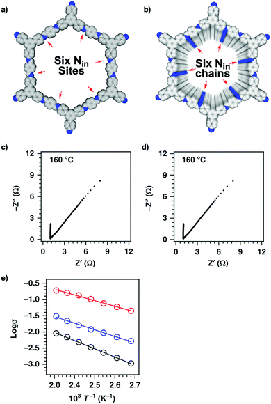 | ||
| Fig. 143 (a) Reconstructed structure of one hexagonal macrocycle (grey, C; blue, N; CH3 units and H are omitted for clarity). One hexagon has six Nin sites on each edge. (b) Reconstructed structure of a 1D channel; only 20 layers are shown. The 1D channel possesses six Nin chains, with one on each of the pore walls; the Nin site is separated by 3.52 Å along the z direction. (c) Nyquist plots of H3PO4@TPB-DMeTP-COF measured at 160 °C under anhydrous conditions. (d) Nyquist plot of H3PO4@TPB-DMeTP-COF after a 20 h continuous run at 160 °C. (e) Temperature profiles of the proton conductivities of H3PO4@TPB-DMeTP-COF (red circles and line), 75%H3PO4@TPB-DMeTP-COF (blue circles and line) and 50%H3PO4@TPB-DMeTP-COF (black circles and line). Circles are experimental data and lines are curve fitting results. Adapted with permission from ref. 559, Copyright 2020 Springer Nature. | ||
TPB-DMeTP-COF has a pore size of 3.36 nm and a high pore volume of 1.60 cm3 g−1; the high pore volume allows for a high loading content of H3PO4. Indeed, loading H3PO4 into the pores of TPB-DMeTP-COF achieves a high content of 266.6 wt% and yields H3PO4@TPB-DMeTP-COF; the content is close to the theoretical one based on the pore volume and H3PO4 density. The anhydrous proton conductivity of H3PO4@TPB-DMeTP-COF is 1.91 × 10⁻¹ S cm−1 at 160 °C (Fig. 143d), which remains constant during a 20 h run (Fig. 143e). The conductivity is even twice as high as that of molten neat H3PO4 (1 × 10⁻¹ S cm−1). H3PO4@TPB-DMeTP-COF shows an Ea value of 0.34 eV (Fig. 143e, red curve), suggesting a hopping mechanism for proton transport across the 1D channels. Remarkably, the reorganisation energy of proton transport is only 0.12 eV and the diffusion rate constant at 110 °C reaches 6.28 × 10⁻⁴ cm2 s−1.
In order to disclose the effect of the H3PO4 network on proton transport, 75%H3PO4@TPB-DMeTP-COF and 50%H3PO4@TPB-DMeTP-COF have been synthesised to load H3PO4 with three-fourth and half of the theoretical loading content, respectively. The 75%H3PO4@TPB-DMeTP-COF and 50%H3PO4@TPB-DMeTP-COF samples exhibit decreased proton conductivities of 3.05 × 10⁻² and 9.04 × 10⁻³ S cm−1 at 160 °C, respectively. Temperature-dependent profiles reveal that the Ea value is 0.40 eV for 75%H3PO4@TPB-DMeTP-COF (Fig. 143e, blue curve) and 0.50 eV for 50%H3PO4@TPB-DMeTP-COF (Fig. 143e, black curve). Interestingly, the decrement degree with the H3PO4 content is much smaller than those of polybenzimidazoles. This effect stems from the unique structure of COFs in which the vertically aligned dense N chains on the pore walls maintain an unbroken H3PO4 network even in the case of low content, which provides pathways for proton conduction. However, such a structural feature is inaccessible with polybenzimidazoles.
This work thus showcases a strategy based on COFs for designing proton-transporting materials by engineering channel walls to produce dually stable frameworks. The principle of a COF material to achieve anhydrous proton conduction is three-fold: (1) the framework stability, (2) the proton network stability and (3) the pore volume of COFs, which defines proton carrier density in the material. The 1D channels are fully accessible to H3PO4, while the proton conductivity is controlled by the continuum of the proton network in the pores. A full loading constitutes a continuous network to enable proton super flow. COFs enable design and synthetic control of 1D nanochannels; these results demonstrate a start line for designing anhydrous proton conduction and applications in energy conversion.
12.2 Lithium ion transport
Different from proton transport, Li+ ion conduction requires polyelectrolytes such as poly(ethylene oxide) (PEO) interfaces.371 The ordered channels of COFs offer the space for loading Li+ salts and enable Li+ ion transport across the materials. Therefore, Li+-conducting COFs offer a platform for designing polyelectrolytes for lithium ion batteries. There are two major approaches to explore solid-state Li+-conducting COFs: one is based on bare pores without functional units on the pore walls to explore the pore size and shape effects and the other is based on functionalised pore walls by exploring various polyelectrolyte interfaces to control ion loading and transport. Lithium ion conduction relies on ion concentration and ion mobility. In lithium salts, Li+ ions are strongly associated with their anions via ionic bonds, even forming ionic aggregates. The ion pairs and aggregates impede ionic diffusion and result in slow ion motion. How to break up ion pairs in solid-state conductors is key to ion conduction, which is the reason for the pore interface engineering of COFs.COF-5 (Fig. 14a) and TpPa-1 COF (Fig. 63e) have been immersed in a THF solution of LiClO4 for 2 days to load 3.77 mol% Li+ ions.560 The resulting pellets exhibit ionic conductivities of 2.6 × 10⁻⁴ and 1.5 × 10⁻⁴ S cm−1, respectively, at room temperature (Fig. 144). In contrast, the COF pellets free of Li+ salts are inactive for ion conduction. In the case of COF-5, the Ea value is 0.37 ± 0.004 eV.
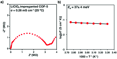 | ||
| Fig. 144 (a) Complex impedance function and (b) Arrhenius plot of COF-5 impregnated with LiClO4. Adapted with permission from ref. 560, Copyright 2016 ACS. | ||
With a hexa-coordinated germanate knot and an anthracene linker, LiPF6@Ge-COF-1 (Fig. 145a) shows Li+ ion conductivities of 2.5 × 10⁻⁴ and 3.5 × 10⁻³ S cm−1 at 30 °C and 100 °C, respectively. The germanate site has a low charge and decreases the affinity with Li+ ions.561 Anionic spiroborate-linked ICOF-2 with Li+ counterions (Fig. 34e) upon mixing with polyvinylidene difluoride (PVDF) forms a membrane. The resulting membrane exhibits an ionic conductivity of 3.05 × 10⁻² S cm−1 at room temperature, with an Ea value of 0.24 eV.562
2D cationic CON-Cl with Cl− counteranions is transformed into CON-TFSI by exchanging Cl− anions with TFSI− anions. CON-TFSI upon mixing with LiTFSI yields Li-CON-TFSI (Fig. 145b). Li-CON-TFSI exhibits a conductivity of 2.09 × 10⁻⁴ S cm−1 at 70 °C, with an Ea value of 0.34 eV. FT-IR spectroscopy reveals that the carbonyl groups on the pore walls coordinate with Li+ ions and thus promote their transport.564 2D imidazolium cationic Im-COF-Br with Br− counteranions is transformed into Im-COF-TFSI (Fig. 145c). Im-COF-TFSI upon introduction of LiTFSI yields Im-COF-TFSI@Li which exhibits a conductivity of 4.04 × 10⁻⁴ S cm−1 at 80 °C with an Ea value of 0.32 eV.565 Im-COF-TFSI@Li shows a voltage window of 4.2 V, suggesting electrochemical stability. A lithium ion battery with Im-COF-TFSI@Li electrolyte achieves a stable voltage curve over 300 h at a current density of 0.10 mA cm−2, suggesting that Im-COF-TFSI@Li forms a stable interface with the Li electrode.
A series of imidazolate COFs, i.e. H-ImCOF, CH3-ImCOF and CF3-ImCOF, with different substituents (H, CH3 and CF3) on the imidazole N site have been developed to be treated with n-BuLi for introducing Li+ ions onto the imidazole sites to form H-Li-ImCOF, CH3-Li-ImCOF and CF3-Li-ImCOF, respectively (Fig. 145d). H-Li-ImCOF, CH3-Li-ImCOF and CF3-Li-ImCOF with Li+ contents of 2.7%, 1.4% and 1.1% exhibit conductivities of 5.3 × 10⁻³, 8.0 × 10⁻⁵ and 7.2 × 10⁻³ S cm−1, with Ea values of 0.12, 0.27 and 0.10 eV, respectively (Fig. 146a and b). The different conductivities are dependent on the electronic properties of the pore walls. The CF3 group owing to an electron withdrawing effect induces positive charges on the imidazole ring, which helps in dissociating Li+ ion pairs and promoting Li+ ion transport.235
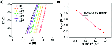 | ||
| Fig. 146 Electrochemical measurements of H-Li-ImCOF pellets solvated with propylene carbonate (PC): (a) Nyquist plots of electrochemical impedance spectroscopy (EIS) measurements made over a range of temperatures and (b) Arrhenius plot of ionic conductivity as a function of temperature. Adapted with permission from ref. 235, Copyright 2019 ACS. | ||
COFs accommodate polymer chains via physical traps in the pores and enable the synthesis of polyelectrolytes. For example, loading polyethylene glycol (PEG; MW = 1000) into DBC-2P forms DBC-2P⊂PEG-28% with a PEG content of 28 wt% (Fig. 29f). DBC-2P⊂PEG-LiBF4 is prepared by complexation of PEG with LiBF4 and achieves an ionic conductivity of 6.16 × 10⁻⁹ S cm−1 under anhydrous conditions (Fig. 147).352
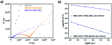 | ||
| Fig. 147 (a) EIS spectra of DBC-2P⊂PEG-LiBF4, DBC-2P%PEG-28 wt% and DBC-2P at 70 °C at 98% RH. (b) Arrhenius plots of DBC-2P⊂PEG-28 wt% (blue) and DBC-2P⊂PEG-LiBF4 (purple). Adapted with permission from ref. 352, Copyright 2019 Wiley-VCH. | ||
The structure of pore walls affects the loading of polyelectrolyte and controls ion conduction. Four different COFs, i.e. CD-COF (Fig. 145e) with an anion skeleton, EB-COF-ClO4 with a cationic skeleton and COF-5 (Fig. 14a) and COF-300 (Fig. 121c) with neutral skeletons, have been synthesised to load PEG (MW = 800) for Li+ ion transport. PEG and LiClO4 are loaded into these COFs to yield PEG-Li+@COFs via physical traps. The conductivities of PEG-Li+@CD-COF-Li, PEG-Li+@COF-300, PEG-Li+@COF-5 and PEG-Li+@EB-COF-ClO4 are 1.30 × 10⁻⁴, 9.11 × 10⁻⁵, 3.49 × 10⁻⁵ and 1.78 × 10⁻³ S cm−1 at 120 °C, respectively. The higher conductivity of PEG-Li+@EB-COF-ClO4 compared to those of PEG-Li+@CD-COF-Li, PEG-Li+@COF-300 and PEG- Li+@COF-5 originates from the fact that the cationic skeleton traps anions and promotes dissociation of ionic pairs (Fig. 148).
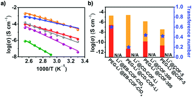 | ||
| Fig. 148 (a) Arrhenius plots of PEG-Li+@EB-COF-ClO4 (orange), PEG-Li+@CD-COF-Li (blue), PEG-Li+@COF-300 (red), PEG/Li+/EB-COF-ClO4 (gray), PEG-Li+@COF-5 (purple) and Li+@CD-COF-Li (green) ionic conductivity. (b) Ionic conductivities and TLi+ of PEG-Li+@COFs and Li+@COFs at 30 °C. The red area indicates the contribution of Li+ conduction, while the orange area shows the contribution of anion conduction. Adapted with permission from ref. 563, Copyright ACS 2019. | ||
TpPa-SO3H with sulphonic acid groups on the pore walls is transformed into TpPa-SO3Li (Fig. 139f) via reaction with LiOAc to achieve a Li+ content of 2.31 wt%.566 TpPa-SO3Li exhibits a BET surface area of 348 m2 g−1 and a pore size of 1.18 nm. TpPa-SO3Li exhibits a conductivity of 2.7 × 10⁻⁵ S cm−1 at room temperature and an Ea value of 0.18 eV, suggesting a hopping mechanism (Fig. 149). TpPa-SO3Li shows a high Li+ ion transference number of 0.9, suggesting that Li+ ions dominate the conduction. Owing to the lack of external Li+ ions loaded into the pores, the conduction is based on interlayer Li+ ion transport between the sulphonyl groups on the pore walls. Tp-based COFs (Fig. 63e) have been developed for lithium ion batteries. A COF-protected symmetric cell achieves a Li+ ion conductivity of 0.53 mS cm−1 at room temperature, which is superior to that of an original lithium cell (0.17 mS cm−1). The cell exhibits a capacity of 3.8 mA h cm−2 and enables 150 cycles.567
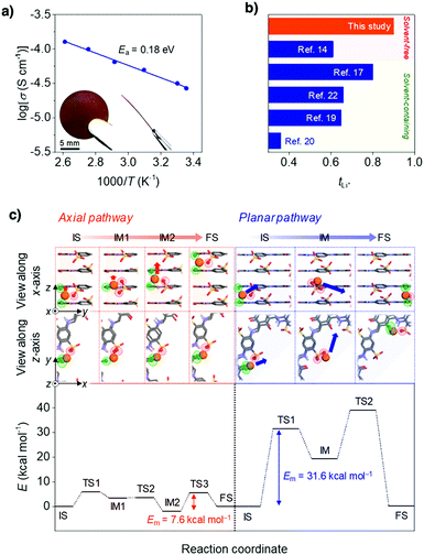 | ||
| Fig. 149 (a) Arrhenius plot for the ionic conductivity of TpPa-SO3Li. (The insets show photographic images of the self-standing pellet.) (b) TLi+ values of TpPa-SO3Li and previously reported porous crystalline ion conductors (cationic COF/LiTFSI, spiroborate-linked COF/PVdF/PC, Cu azolate MOF/LiBF4/PC, Cu3(btc)2 MOF/LiClO4/PC and Cu porphyrin−Zr cluster-based MOF/Li0.2EMIm0.8TFSI; TFSI− = bis(trifluoromethanesulphonyl)imide, btc3− = benzene-1,3,5-tricarboxylate, EMIm+ = 1-ethyl-3-methyl-imidazolium). (c) Theoretical elucidation of Li-ion migration behaviours inside the pore (top) with the corresponding energy diagrams (bottom). The initial, intermediate, transition and final states are abbreviated as IS, IM, TS and FS, respectively (orange: Li, white: H, black: C, blue: N, red: O, yellow: S, green: O atoms of the keto groups that are bound to Li+ ions). Adapted with permission from ref. 566, Copyright 2019 ACS. | ||
Introducing defects into COFs has been investigated for Li+ ion transport. Defective dCOF-NH2-Xs (X indicates the percentage of end-capping units) are synthesised by combining monoaldehyde DHA with dialdehyde DHTA as linkers (Fig. 55h). The dCOF-NH2-Xs are transformed into positively charged dCOF-ImTFSI-Xs by reacting with ImBr followed by ion exchange with ImTFSI. dCOF-ImBr-60 exhibits a Li+ ion conductivity of 1.03 × 10⁻³ S cm−1 at 80 °C with a low activation energy of 0.28 eV. This conductivity is superior to that of the defect-free COF (3.44 × 10⁻⁶ S cm−1). The improved conductivity is attributed to the N–H⋯F hydrogen bonds between the amine N–H group and the F atom of TFSI−, which facilitate the dissociation of Li+ ion pairs. Notably, dCOF-ImTFSI-60 exhibits a high conductivity of 7.05 × 10⁻³ S cm−1 at 150 °C, demonstrating good thermal stability.568
Owing to the limited number of ionic sites on walls, cationic COFs are not enough to form an interface that promotes Li+ ion pair dissociation and conduction. How to design a polyelectrolyte interface in COFs and to enable a full use of the structural features of COFs is a challenging goal.
We have developed a strategy for the pore surface engineering of COFs to construct tailor-made polyelectrolyte interfaces. Designing a polyelectrolyte interface within the 1D channels of COFs promotes ionic bond dissociation and facilitates Li+ ion conduction. TPB-BMTP-COF with flexible oligo(ethylene oxide) chains on the pore walls has been synthesised by condensing TPB and BMTP (Fig. 34b), while TPB-DMTP-COF has been synthesised by using the DMTP linker to hold methoxy groups on the edge phenyl units. TPB-DMTP-COF exhibits a surface area of 2458 m2 g−1 and a pore volume of 1.34 cm3 g−1. Upon replacement of the methoxy groups with oligo(ethylene oxide) chains, the surface area of TPB-BMTP-COF decreases to 1746 m2 g−1 with a pore volume of 0.96 cm3 g−1, while the pore size decreases from 3.26 to 3.02 nm. TPB-BMTP-COF retains crystallinity and porosity after loading LiClO4 into the pores and exposing to air for over one month. This approach by pore surface engineering with oligo(ethylene oxide) chains addresses the issues of PEO electrolytes, which form a rigid crystalline structure so that the ion motion is greatly impeded. Li+@TPB-BMTP-COF exhibits an ionic conductivity of 1.66 × 10⁻⁴ S cm−1 at 80 °C (Fig. 150a), which is 30-fold that of Li+@TPB-DMTP-COF. Notably, Li+@TPB-BMTP-COF shows an ionic conductivity of 5.49 × 10⁻⁴ S cm−1 at 90 °C, which remains constant after 24 h. These results are remarkable as the ionic conductivity of the PEO-Li+ complex is only 8.0 × 10⁻⁸ S cm−1 at 40 °C. TPB-BMTP-COF (Fig. 150b, red curve) and TPB-DMTP-COF (Fig. 150b, black curve) have Ea values of 0.87 and 0.96 V, respectively, suggesting that Li+ ion transport in the channels is via the vehicle mechanism (Fig. 150).371 TPB-DMTP-COF loaded with LiTFSI has been used to fabricate Li-SeS2 batteries to achieve a Li+ ion diffusion coefficient of 3.47 × 10⁻¹⁰ and shows cycling stability.569
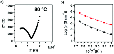 | ||
| Fig. 150 (a) Nyquist plots of Li+@TPB-BMTP-COF measured at 80 °C. (b) Temperature dependencies of the ion conductivities of Li+@TPB-DMTP-COF (black) and Li+@TPB-BMTP-COF (red). Adapted with permission from ref. 371, Copyright 2018 ACS. | ||
The greatly enhanced Li+ ion conductivity originates from the pore surface engineering of dense oligo(ethylene oxide) chains that form a polyelectrolyte interface in the channels upon complexation with Li+ ions. The polyelectrolyte chains are flexible and extrude from the pore walls, which assist the dissociation of ionic bonds and offer a pathway for vertical Li+ ion transport between neighbouring oligo(ethylene oxide) chains of two layers with a separation of 3.5 Å. This work thus offers a general strategy for engineering polyelectrolyte pore wall interfaces to design ion-conducting COFs.
Similarly, engineering PEO polyelectrolyte interfaces by directing self-assembly to pre-organise functional groups into building blocks has been developed. Three PEO-engineered hydrazone-linked COFs have been synthesised by condensing 1,3,5-triformylbenzene with three hydrazide monomers with PEO chains of different lengths. The resulting COF-PEO-X (Fig. 145f) (X = 3, 6 and 9), in which X is the number of EO units, have BET surface areas of 13, 4 and 5 m2 g−1, as the X is increased from 3 to 6 and 9, respectively. This result indicates that the pores are fully occupied with PEO chains. The COF-PEO-X upon treatment with a THF solution of LiTFSI form COF PEO-X-Li, with O/Li weight ratios of 8.8/1, 7.5/1 and 5.9/1 for COF-PEO-3-Li, COF-PEO-6-Li and COF-PEO-9-Li, respectively.570 The glass transition temperatures of COF-PEO-6-Li and 9-Li are 27 and 32 °C, respectively. COF-PEO-3-Li, COF-PEO-6-Li and COF-PEO-9-Li exhibit conductivities of 9.72 × 10⁻⁵, 3.71 × 10⁻⁴ and 1.33 × 10⁻³ S cm−1, respectively, at 200 °C. The conductivity for COF-42-Li without PEO chains is 1.77 × 10⁻⁸ S cm−1, which is 5 orders of magnitude lower than that of COF-PEO-9-Li-9. Importantly, COF-PEO-9-Li retains conductivity over 12 h at 200 °C. Generally, lithium ion batteries hardly work at temperatures above 80 °C, owing to unstable liquid electrolytes. Lithium ion batteries based on Li/COF-PEO-9-Li electrolyte show a stable working voltage of 5.2 V versus Li/Li+ at 100 °C. The capacity is stable at 120 mA h g−1 over 10 cycles. These results suggest that COF-PEO-X-Li are solid electrolytes with thermal and electrochemical stability.
Pore surface engineering allows the construction of tailor-made pore interfaces for promoting Li+ ion transport. We have explored a series of polyelectrolyte COFs using stable TPB-DMTP-COF and TPB-BMTP-COF as base skeletons and integrating different electrolyte chains onto their pore walls. Integrating tetra(ethylene oxide) units (TEO; C8H17O4) into the pore walls of TPB-DMTP-COF and TPB-BMTP-COF (Fig. 31d–f) allows the development of two series of COFs whose walls are engineered with methoxy/TEO or TriEO/TEO sequences at discrete ratios.367 A series of COFs, including [TEO]0.33-TPB-DMTP-COF, [TEO]0.5-TPB-DMTP-COF, [TEO]0.33-TPB-BMTP-COF, [TEO]0.5-TPB-BMTP-COF and [TEO]1-TPB-BPTA-COF with walls fully engineered with the TEO chains, are synthesised for loading LiClO4 to produce Li+@[TEO]0.33-TPB-DMTP-COF, Li+@[TEO]0.5-TPB-DMTP-COF, Li+@[TEO]0.33-TPB-BMTP-COF, Li+@[TEO]0.5-TPB-BMTP-COF and Li+@[TEO]1-TPB-BPTA-COF, respectively. In this series, Li+@[TEO]0.5-TPB-DMTP-COF exhibits the highest ion conductivity of 2.49 × 10⁻⁴ S cm−1 at 80 °C. Li+@[TEO]0.5-TPB-DMTP-COF retains conductivity over a 48 h continuous run at 90 °C.
In order to obtain insights into the role of polyelectrolyte chains, we excluded the effect of ion concentration by normalizing ion conductivity with the ion content using TPB-DMTP-COF, which has the highest Li+ content as a standard. Remarkably, Li+@[TEO]0.33-TPB-DMTP-COF and Li+@[TEO]0.5-TPB-DMTP-COF with TEO chains increase the ion mobility by 336 and 1490 times, respectively (Fig. 151). The polyelectrolyte interface increases the ion mobility not in a linear fashion but in an exponential mode; the ion mobility can be increased by more than three orders of magnitude by tuning the pore interface. This strategy enables a quantitative correlation between interfaces and ion transport and unveils a full picture of managing ionic interfaces to achieve ion transport.367
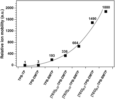 | ||
| Fig. 151 The relative ion mobility of Li+@COFs at 40 °C normalized by the Li+ content of Li+@TPB-TP-COF. Adapted with permission from ref. 367, Copyright 2020 Wiley. | ||
12.3 Anion transport
Anion exchange fuel cells are an emerging class of fuel cells owing to the possibility of using non-precious-metal catalysts. The anion exchange membrane (AEM) is key to anion exchange fuel cells. One approach to make effective AEM materials is to functionalise the pore walls of cationic groups via heterogeneous post-synthetic modification. The β-ketoenamine-linked 2D TpBD-Me2OA+OH− with quaternary ammonium groups (Fig. 152a) shows a bicarbonate conductivity of 5.3 × 10⁻³ S cm−1 at 20 °C and 2.7 × 10⁻² S cm−1 at 80 °C, with a low swelling ratio of <1.0% at 20 °C compared to commercial materials.571 The quaternary ammonium cations offer the pathway for bicarbonate anion transport across the pores. COF-LZU1 (Fig. 67o) has been developed for AEMs by incorporating quaternary ammonium cations into the framework and blending with brominated poly(2,6-dimethyl-1,4-phenylene oxide) (BPPO). The resulting QA@COF-LZU1/PPO hybrid membrane with a QA@COF-LZU1 content of 5 wt% exhibits an OH− anion conductivity of up to 1.68 × 10⁻¹ S cm−1 at 80 °C.572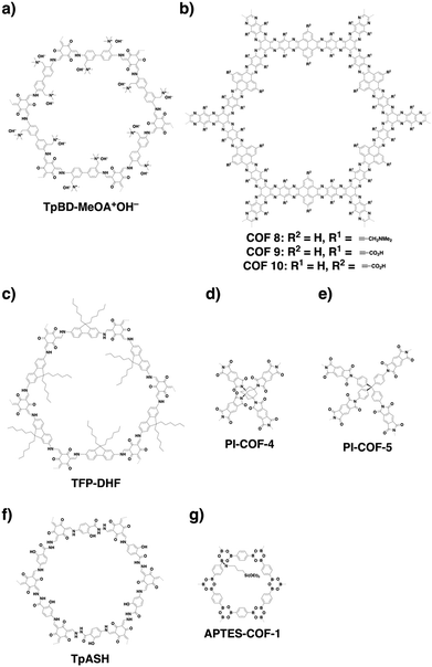 | ||
| Fig. 152 Structures of COFs for (a) anion transport, (b and c) neutral molecule transport and (d–g) drug delivery. | ||
12.4 Neutral molecule transport
Water transport is related to water purification and seawater desalination. Incorporating TpHZ COF (Fig. 79d) nanosheets into poly(ether sulphone) (PES) yields a PES/TpHZ membrane. The PES/TpHZ membrane exhibits a permeation flux of 2.48 kg m−2 h−1 and a high separation factor of 1430.573 Similarly, a hybrid nanosheet (GO-CTF5) obtained by mixing GO with CTF5 (Fig. 14m) shows a water flux of 226.3 ± 9.9 L m−2 h−1 bar−1. In this case, covalent grafting of NH2-functionalised CTF nanosheets onto carboxylic acid-functionalised GO nanosheets forms extra through-plane channels, which shorten the transport pathway.574 Hollow H-TpBD COF (Fig. 63f) nanospheres with sodium alginate (SA) matrices are fabricated into hybrid SA-H-TpBD. H-TpBD provides a hydrophobic surface, while microporous channels and the hollow structure enhance the water flux penetration. The as-fabricated hybrid shows a permeation flux of 2.17 kg cm−2 h−1 and a separation factor of 2099 for dehydrating 90 wt% ethanol aqueous solution at 76 °C.575COF 8, COF 9 and COF 10 (Fig. 152b) have been synthesised by condensing hexaazatrinaphthalene with pyrene tetraone, producing COFs with stable aromatic backbones and functionalised pores. Carboxylate groups produce negatively charged pores, while tertiary amine groups introduce positive charges.576 The hydrophilic nanopores of COF 9 facilitate water transport across nanochannels and achieve a water permeance of 2260 L m−2 h−1 bar−1 (Fig. 153).
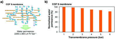 | ||
| Fig. 153 (a) Sketch of water transport pathways through COF 9 membranes. (b) The effect of the transmembrane pressure on water permeance through COF 9 (post-treatment at 80 °C for 5 min). Adapted with permission from ref. 576, Copyright 2018 ACS. | ||
Computational non-equilibrium molecular dynamics simulations reveal that single-layered or multi-layered TpPa-1 (Fig. 63e) has permeability, which is three orders of magnitude higher than those of commercial nanofiltration membranes. The permeability decreases as the number of layers is increased and the pore size is decreased. An equation, Rtotal = 2.01 × 1033lmem + 0.37 × 1033, where Rtotal is the total resistance and lmem is the thickness of the membrane, is proposed to predict the water permeance.577
Nanofiltration of organic solvents needs membranes with pore sizes of 1–2 nm to carry out concentration, exchange and purification. COFs with controlled pore sizes are suitable for nanofiltration. TFP-DHF COF (Fig. 152c) forms a continuous and crystalline membrane using the Langmuir–Blodgett method.578 The as-prepared membrane exhibits a hexane permeance of over 180 L m−2 h−1 bar−1, which is 100 times higher compared to the amorphous analogue.
12.5 Drug delivery
Nanocarriers are a unique class of drug-delivery materials that could address the issues of direct implementation, including poor stability, dispersibility, low cell membrane permeability, nonspecific targeting and uncontrollable release. A wide range of materials, including MOFs, hydrogels, nanoparticles and quantum dots, have been developed as nanocarriers.579–581 The controllable pore size, structural diversity and absence of toxic metal ions make COFs an attractive platform for drug delivery.2793D PI-COF-4 and PI-COF-5 (Fig. 152d and e) have pore sizes of 1.3 and 1.0 nm, respectively, which are large enough to trap a painkiller drug – ibuprofen (IBU, molecular dimensions 5 Å × 10 Å).65In vitro experiments reveal that for both PI-COFs the majority of IBU is released after 6 days, while the final delivery reaches 95% of loaded IBU. A series of PI-n-COFs, i.e. PI-3-COF and PI-2-COF (Fig. 82a and 137f) with pore sizes of 1.1 and 1.4 nm, respectively,279 have been tested for delivery of an anti-cancer drug, 5-FU. PI-2-COF and PI-3-COF show loading capacities of 10 wt% and 30 wt%, respectively. Most loaded 5-FU is released after 3 days. The final release reaches 85% of loaded 5-FU after 3 days. Notably, PI-n-COFs exhibit low cytotoxicity and are promising for in vivo application. The lone pair of nitrogen in the COFs serves as hydrogen-bonding acceptors to attract drugs. For example, imine-linked TTI-COF (Fig. 82a) loaded with Quercetin, an anti-cancer dietary flavonoid, has been tested for in vitro drug delivery.582 Interestingly, TTI-COF is biocompatible and does not induce cytotoxicity to normal cells but causes apoptosis of cancer cells (Fig. 154).
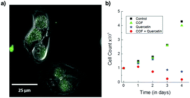 | ||
| Fig. 154 (a) COF uptake by MDA-MB-231 carcinoma cells as seen in the merged phase contrast and green fluorescence channel image under a fluorescence microscope. (b) Proliferation assay of the cancer cells treated with the COF (green triangles), Quercetin (blue stars) and the Quercetin-loaded COF (red dots) over a period of 4 days. The control experiment is shown as black squares. Adapted with permission from ref. 582, Copyright 2016 Wiley-VCH. | ||
TpASH has been exfoliated into CONs (Fig. 152f)230 to load 12% 5-FU, which is higher than those (maximum 5%) of biocompatible polymers such as poly(ethylene glycol)-4000, polyvinylpyrrolidone and poly(lactic acid). The CONs of TpASH constantly release 5-FU to 74% of the loaded amount after 72 h (Fig. 155). By conjugating with the cellular targeting ligand folic acid, the resulting TpASH-FA enables pinpoint delivery of 5-FU to breast cancer cells.
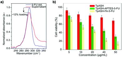 | ||
| Fig. 155 (a) Drug loading study of 5-FU by UV-vis. (b) MTT assay on MDA-MB-231 cell lines showing cellular viability. Adapted with permission from ref. 230, Copyright 2017 ACS. | ||
For in vivo drug delivery, a polymer–COF nanocomposite, PEG-CCM@APTES-COF-1 (Fig. 152g), has been synthesised by self-assembly of PEG-modified curcumin derivatives and COF-1.583 The self-assembled micelle exhibits fluorescence, which tracks the process of COF nanocarriers in cellular uptake and drug release. An anticancer drug, doxorubicin (DOX), is loaded into the pores of COF-1 via a hydrophobic effect. PEG-CCM@APTES-COF-1 has an encapsulation efficiency of 90.5 ± 4.1% and reaches a loading capacity of 9.71 ± 0.12 wt%. In vitro experiments reveal that the DOX-loaded nanocomposite enters cells via endocytosis and inhibits the growth of HeLa cells without affecting normal cells. In vivo tests demonstrate that DOX is retained in the bloodstream and is gradually released into tumour cells owing to the acidic decomposition of COF-1 (Fig. 156). The PEG-CCM@APTES-COF-1@DOX suppresses tumour growth efficiently in mice without noticeable relapse.
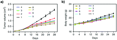 | ||
| Fig. 156 (a) Mean tumour volumes after excision on day 28 (n = 5). (b) Body weights of the mice in different groups after treatment at different time intervals. Relative antitumour assay after intravenous injection into the HeLa tumour-bearing mice with saline (1), free DOX (2), PEG350-CCM@APTES-COF-1 (3), PEG1000-CCM@APTES-COF-1 (4), PEG2000-CCM@APTES-COF-1 (5), PEG350-CCM@APTES-COF-1@DOX (6), PEG1000-CCM@APTES-COF-1@DOX (7) and PEG2000-CCM@APTES-COF-1@DOX (8) at an equivalent dose of 1.5 mg DOX kg−1 in PBS every 3 days. Data are presented as means ± SD (n = 5). Each data point represents the average and SD (one above and one below for the error bars), as measured from five different analyses in a single experiment. Adapted with permission from ref. 583, Copyright 2018 Springer Nature. | ||
These results showcase the possibility of exploring the skeletons and pores of COFs to design nanocarriers that enable controlled and targeted delivery of drugs.
13. Perspectives and summary
Rapid progress over the past decade in the design and synthesis of organic materials has shaped up the field of COFs. Especially, the design principle based on geometry matching and topology diagrams has established the basis of the field, while synthetic reactions have produced a huge number of structures and materials, demonstrating that COFs offer an irreplaceable platform for designed synthesis of tailor-made frameworks and organic materials with long-range structural orderings. Based on the diversity of structures and functionalities, COFs have shown great potential in various applications. Nevertheless, there are still key fundamental issues to be addressed from the perspectives of chemistry, physics and materials science.From the perspective of chemistry, the exploration of topology diagrams is one of the important issues to be addressed in the future. The current topology diagram is mainly based on the combination of monomers with symmetric geometry. The possibilities of using asymmetric units as monomers for polycondensation have been demonstrated for certain cases; further studies on combinations of knots and linkers with asymmetric geometry would enable the exploration of specific topologies while retaining high crystallinity and porosity. Such an attempt will also expand the scope of structural complexity in terms of both skeletons and pores. The investigation of the multicomponent strategy for both knots and linkers is of great interest for knitting organic units into ordered frameworks to create anisotropic tiling and unusual pores, which are inaccessible to other porous materials. Using chiral units to design chiral COFs requires the further expansion of monomer and skeleton diversities. One important issue is that the chirality of the resulting COFs remains to be well addressed; so far, this important concern has been ignored for most chiral COFs.
COFs are synthesised by various polycondensation reactions. However, many cases yield frameworks with limited crystallinity and porosity. How to explore these reactions to produce highly crystalline frameworks remains a substantial challenge. In certain cases, the reported COFs hardly retain their high crystallinity, and this affects the reproducibility of the results. Investigation of the crystal formation process is essential for disclosing the reaction parameters that affect their crystallinity. Studies along this direction will help in understanding the nucleation and crystallisation processes and in revealing their mechanisms, which will lead to the finding of ways to synthesise single crystals. Investigation of morphology control to understand how to generate well-defined macroscopic shapes at different scales is an aspect that needs to be well addressed, with the aim of elucidating the time course and spatial growth of COF crystallites. Little has been known so far about this important part.
Exploration of new reactions is crucial to the COF's field and deserves further efforts as new reactions yield new structures and properties. Recently, both reversible and irreversible reactions have been developed for the synthesis of COFs. To understand the mechanism of reactions that guides the formation of crystalline covalent networks is one of the important subjects worthy of investigation. In relation to new reactions, the exploration of new monomers to produce COFs will not only expand their structure diversity but also broaden the scope of properties and functions. Studies in these directions form a major driving force in developing the COF field.
In addition to the efforts on bulk polymerisation, the exploration of methodologies to produce films and membranes is a subject worthy of further investigations. Although various methods including the Langmuir technique, assembled monolayer and interfacial polymerisations at various interfaces have been tested, they are far from ideal. The main drawback of current films and membranes is their weak ordering and/or almost amorphous nature. This means that we need to explore new methodologies that enable the production of large-area homogeneous films and/or membranes that retain the ordered structures of COFs rather than non-ordered domain structures. Studies in these directions will also exert a direct impact on using COF materials in various applications including separation, purification, catalysis, and energy conversion and storage.
From the perspective of physics, the elucidation of the interactions of COFs with photons, excitons, phonons, electrons, holes, spins, ions and molecules is the most fundamental subject in exploring the field of COFs. These interactions can be explored at different spatiotemporal scales; the monolayer or a few layers, as well as bulk crystallites, are interesting subjects to be addressed. Unlike 1D linear and 3D amorphous polymers, 2D and 3D COFs with structural orderings can trigger specific interactions and thus they are expected to behave differently. To reveal these interactions is essential for identifying the uniqueness and nature of COFs. However, the efforts so far in these directions are not enough; this insufficiency is partially related to the quality of COF crystallites. To increase the quality of samples is of prime importance in elucidating the physics of COFs. The current status is largely based on the bulk materials that contain various particles with complex boundaries. The observed phenomena are thus an average of various COF particles, lacking a discrete structure–property correlation. This can be addressed by using single particles and/or single layers with well-defined structural orderings. In relation to this, studies on structural defects and their impact on interactions are of great importance in understanding the development of properties and functions. These understandings will finally lead to the formation of theories or rules about COFs.
From the perspectives of materials science and engineering, the development of various devices to show the unique performance that is inherent to COF structures is of great importance. Depending on the properties and functions, different COFs are required to be present in different forms, including single layers, few layers, bulk crystallites, films and membranes. One important issue is how to produce homogeneous materials while retaining ordered skeletons and pores throughout the devices.
The exploration of gas adsorption or molecular separation needs precise control over pore dimensions. Not only are the pore shape, corner groove and pore size, but the pore interface is also important to control the interactions with guest molecules that lead to selective adsorption and separation. In this sense, COFs still have enough room to design these structural parameters so that a specific nanospace can be precisely constructed for targeting a specific guest. Various gases and vapours, metal ions and organic compounds have been adsorbed and separated using COFs; one significant feature is that the open channels of COFs are highly accessible to guests as demonstrated by various gases, vapours, ions and molecules. This feature implies that the adsorption and/or capture capacities merely rely on the pore volume of COFs. Therefore, a general principle for designing COFs is to maximise the capacity by tuning the pore volume to reach the highest value and to optimise the selectivity by designing pore sizes, shapes and interfaces. Along this line of study, COFs will have the chance to offer a way to size- and/or shape-based separations as well as molecular recognition of small gas molecules as well as large organic compounds. Computational approaches will play greater roles and have the power to design such nanospaces by predicting various interactions in confined organic spaces.
The semiconducting properties of COFs are based on built-in columnar π arrays that are topologically aligned over the frameworks and serve as pathways for carrier transport. Distinct from traditional organic semiconductors of small compounds and polymers, the topology-guided alignment of columnar π arrays is unique to COFs. Such an alignment is even hardly accessible to single crystals of organic semiconductors. By using different combinations of π units, p- and n-type and ambipolar conducting COFs have been discovered. To understand the carrier transport behaviours in COFs is a fundamental issue to be addressed in the future; this contains two aspects: one is the intralayer transport over the 2D polymer sheet and the other is the interlayer transport along the π columns. So far, less attention has been paid to these mechanistic issues. To design semiconductors with balanced hole and electron mobility is of great importance in developing optoelectronic devices. Computational methodology for envisaging carrier transports should be established to elucidate the conducting mechanism and structural impacts. Developing donor–acceptor COFs to form super heterojunctions for photoinduced electron transfer and charge separation offers an ultimate yet ideal molecular mechanism for photoelectric energy conversion and constitutes the core of optoelectronics. Studies along these directions will explore efficient materials for semiconductors and photovoltaics. Developing COFs for application in semiconductor devices requires the preparation of large-area thin films with homogeneous and ordered structures. This is also related to the future directions of design and synthesis of COFs.
The light-emitting property is an important aspect of COFs and has been explored with different π units and linkages. The photoluminescence of COFs is highly dependent on their stacking structures, linkages and building blocks. Designing COFs to achieve high fluorescence quantum yields is a target worthy of further efforts. In relation to this, the luminescence behaviours of single layers, a few layers and bulk crystallites need to be elucidated in a more clear and quantitative way so that the structural parameters that control emission can be identified. On the other hand, the development of COFs as key materials for light-emitting diodes is an interesting subject, as the COF systems consist of interfaced π units that enable hole and electron injection and fusion to produce photons. Studies along this direction are still very limited and deserve our further investigations.
Chemo- and bio-sensing COFs are based on the change in luminescence properties caused by a specific analyte. How to utilise the stacked π columns and pores to enhance the detection sensitivity and responsivity is a subject of particular importance for sensors. To reach a detection limit down to an exceptional level, such as single molecules, is possible if a COF system enables a collective response to the presence of analyte. This requires the design of a specific interface, for example on the pore walls for triggering a cooperative response. Based on a precise molecular design, COFs may not only detect the existence but also tell the nature of the analyte, which should be of great scientific impact.
Energy storage is based on the complementary use of both the skeletons and pores of COFs, whereas the skeleton enables the integration of redox-active sites for triggering redox reactions and the pore allows the transport of ionic species. These synergistic actions provide a chemical basis for COFs to store electricity in their frameworks. How to integrate accessible multielectron redox-active units into the skeleton and how to enable the channels to transport ions at high rates are two key issues to be addressed in achieving capacity and rate performance. The stability of the skeleton is crucial to cycling performance; designing redox-active COFs to be chemically stable is a subject worthy of further efforts.
The development of COFs as various catalysts originates from the diversity of skeletons, which can be designed with various catalytically active sites. For photocatalysis, the design of suitable HOMO and LUMO levels is critical to the photoinduced electron transfer process as well as electron flow to the catalytic sites. Designing seamless pathways that can reduce backward electron transfer and decrease re-organisation energy is a systematic subject that requires precise tuning of all redox steps and intermediates involved in the energy conversion process. Designing electrocatalysts based on COFs requires high electrical conductivity, while the integration of heteroatoms into the frameworks is necessary for achieving high catalytic activity. The integration of these properties into one framework is not an easy task but is worthy of investigation. Exploring COFs as asymmetric catalysts is a subject that has great potential to break through the bottleneck issues of traditional homogeneous catalysts. How to achieve high enantioselectivity, reactivity and recyclability is key to the further development of COF-based heterogeneous asymmetric catalysts.
Integration of metal nanoparticles into COFs for developing catalysts is highly dependent on the size control of metal nanoparticles. It remains a challenge to use COFs for the confinement of nanoparticles of specific sizes; most COFs hardly produce monodisperse metal nanoparticles. Exploring strategies that enable the use of pores or channels to control the size of metal particles is an important aspect that deserves further investigation. In the case of biomimetic catalysts, developing structural advantages of COFs to enhance their reactivity, selectivity and durability is a future direction that would definitely demonstrate the uniqueness of COFs in designing biomimetic catalysts.
Mass transport using COFs is a subject of fundamental importance as their 1D channels are highly ordered, open, accessible and free of any chain entanglement, offering a predesigned pathway for flow. Such built-in channels have been an ideal target over the past few decades in pursuing suitable materials for mass transport. One way to use the channels to transport protons is to construct hydrogen-bonding networks that enable high-rate conduction based on hopping. Designing a COF with a high pore volume that enables the maximum loading of proton carriers offers an efficient way to achieve high proton conductivity. On the other hand, for transport of metal ions, construction of efficient polyelectrolyte systems is necessary to dissociate metal ions from ion pairs and offer pathways for metal ion transport. This requires a balanced design between the density of polyelectrolyte interfaces and pore volume; the density affects the motion of metal ions, while the pore volume determines the content of metal ions in the pores. The pores of COFs are capable of drug encapsulation and release, offering a designable platform for drug delivery. How to develop COFs into a pinpoint or targeted system is a subject worthy of further investigation, while control over the release rate as well as biocompatibility of COFs itself is another important aspect to be addressed in the future.
COFs have shown the strength of chemistry in designing ordered organic materials that is beyond the capacity of traditional polymers and other porous materials; this achievement can be recognised as a big step in polymer science over the past 100 years. We anticipate that the field will broaden the scope and deepen our understandings of this new class of polymers. We believe that further collaboration among chemistry, physics and materials science would definitely bring us to a new era of organic materials with a fascinating full picture, striking nature and large-scale applications of COFs.
Conflicts of interest
There are no conflicts to declare.Acknowledgements
D. J. acknowledges an NUS start up grant (R-143-000-A28-133) and an MOE Tier 1 grant (R-143-000-A71-114).Notes and references
- T. L. Brown, H. E. LeMay and B. E. Bursten, Chemistry: The Central Science, Prentice Hall, 8th edn, 1999 Search PubMed.
- B. H. Bunch and A. Hellemans, The History of Science and Technology, Houghton Mifflin Harcourt, 2004 Search PubMed.
- C. Reinhardt, Chemical Sciences in the 20th Century: Bridging Boundaries, John Wiley & Sons, 2001 Search PubMed.
- R. J. Young, Introduction to Polymers, Chapman & Hall, 1987 Search PubMed.
- J. R. Fried, Polymer Science and Technology, Prentice Hall, 2nd edn, 2003 Search PubMed.
- H. R. Allcock, F. W. Lampe and J. F. Mark, Contemporary Polymer Chemistry, Prentice Hall, 3rd edn, 2003 Search PubMed.
- P. J. Flory, Principles of polymer chemistry, Cornell University Press, 1953 Search PubMed.
- G. Odian, Principles of polymerization, John Wiley & Sons, 1991 Search PubMed.
- M. E. Rogers and T. E. Long, Synthetic methods in step-growth polymers, John Wiley & Sons, 2003 Search PubMed.
- K. Geng, T. He, R. Liu, S. Dalapati, K. T. Tan, Z. Li, S. Tao, Y. Gong, Q. Jiang and D. Jiang, Chem. Rev., 2020, 120, 8814–8933, DOI:10.1021/acs.chemrev.9b00550.
- X. Chen, K. Geng, R. Liu, K. T. Tan, Y. Gong, Z. Li, S. Tao, Q. Jiang and D. Jiang, Angew. Chem., Int. Ed., 2020, 59, 5050–5091 CrossRef CAS.
- S. Wan, J. Guo, J. Kim, H. Ihee and D. Jiang, Angew. Chem., Int. Ed., 2009, 48, 5439–5442 CrossRef CAS.
- C.-Z. Guan, D. Wang and L.-J. Wan, Chem. Commun., 2012, 48, 2943–2945 RSC.
- J. F. Dienstmaier, D. D. Medina, M. Dogru, P. Knochel, T. Bein, W. M. Heckl and M. Lackinger, ACS Nano, 2012, 6, 7234–7242 CrossRef CAS.
- S. Wan, J. Guo, J. Kim, H. Ihee and D. Jiang, Angew. Chem., Int. Ed., 2008, 47, 8826–8830 CrossRef CAS.
- M. Dogru, M. Handloser, F. Auras, T. Kunz, D. Medina, A. Hartschuh, P. Knochel and T. Bein, Angew. Chem., Int. Ed., 2013, 52, 2920–2924 CrossRef CAS.
- Q. Fang, Z. Zhuang, S. Gu, R. B. Kaspar, J. Zheng, J. Wang, S. Qiu and Y. Yan, Nat. Commun., 2014, 5, 4503 CrossRef.
- Z. Li, X. Feng, Y. Zou, Y. Zhang, H. Xia, X. Liu and Y. Mu, Chem. Commun., 2014, 50, 13825–13828 RSC.
- S. Bi, C. Yang, W. Zhang, J. Xu, L. Liu, D. Wu, X. Wang, Y. Han, Q. Liang and F. Zhang, Nat. Commun., 2019, 10, 2467 CrossRef.
- S. Rager, A. C. Jakowetz, B. Gole, F. Beuerle, D. D. Medina and T. Bein, Chem. Mater., 2019, 31, 2707–2712 CrossRef CAS.
- P. Wang, Q. Xu, Z. Li, W. Jiang, Q. Jiang and D. Jiang, Adv. Mater., 2018, 30, 1801991 CrossRef.
- N. Huang, L. Zhai, H. Xu and D. Jiang, J. Am. Chem. Soc., 2017, 139, 2428–2434 CrossRef CAS.
- L. Zhai, N. Huang, H. Xu, Q. Chen and D. Jiang, Chem. Commun., 2017, 53, 4242–4245 RSC.
- A. Acharjya, P. Pachfule, J. Roeser, F. J. Schmitt and A. Thomas, Angew. Chem., Int. Ed., 2019, 58, 14865–14870 CrossRef CAS.
- D. Kaleeswaran, P. Vishnoi and R. Murugavel, J. Mater. Chem. C, 2015, 3, 7159–7171 RSC.
- E. Jin, K. Geng, K. H. Lee, W. Jiang, J. Li, Q. Jiang, S. Irle and D. Jiang, Angew. Chem., Int. Ed., 2020, 59, 12162–12169, DOI:10.1002/anie.202004728.
- Y. Zhao, H. Liu, C. Wu, Z. Zhang, Q. Pan, F. Hu, R. Wang, P. Li, X. Huang and Z. Li, Angew. Chem., Int. Ed., 2019, 58, 5376–5381 CrossRef CAS.
- Y. Zhao, W. Dai, Y. Peng, Z. Niu, Q. Sun, C. Shan, H. Yang, G. Verma, L. Wojtas, D. Yuan, Z. Zhang, H. Dong, X. Zhang, B. Zhang, Y. Feng and S. Ma, Angew. Chem., Int. Ed., 2020, 59, 4354–4359 CrossRef CAS.
- Y. Wang, H. Liu, Q. Pan, C. Wu, W. Hao, J. Xu, R. Chen, J. Liu, Z. Li and Y. Zhao, J. Am. Chem. Soc., 2020, 142, 5958–5963 CrossRef CAS.
- X.-T. Li, J. Zou, T.-H. Wang, H.-C. Ma, G.-J. Chen and Y.-B. Dong, J. Am. Chem. Soc., 2020, 142, 6521–6526 CrossRef CAS.
- W. K. Haug, E. R. Wolfson, B. T. Morman, C. M. Thomas and P. L. McGrier, J. Am. Chem. Soc., 2020, 142, 5521–5525 CrossRef CAS.
- X. Li, J. Qiao, S. W. Chee, H.-S. Xu, X. Zhao, H. S. Choi, W. Yu, S. Y. Quek, U. Mirsaidov and K. P. Loh, J. Am. Chem. Soc., 2020, 142, 4932–4943 CrossRef CAS.
- S. Jhulki, A. M. Evans, X.-L. Hao, M. W. Cooper, C. H. Feriante, J. Leisen, H. Li, D. Lam, M. C. Hersam, S. Barlow, J.-L. Brédas, W. R. Dichtel and S. R. Marder, J. Am. Chem. Soc., 2020, 142, 783–791 CrossRef CAS.
- P.-L. Wang, S.-Y. Ding, Z.-C. Zhang, Z.-P. Wang and W. Wang, J. Am. Chem. Soc., 2019, 141, 18004–18008 CrossRef CAS.
- M. Zhang, J. Chen, S. Zhang, X. Zhou, L. He, M. V. Sheridan, M. Yuan, M. Zhang, L. Chen and X. Dai, J. Am. Chem. Soc., 2020, 142, 9169–9174 CrossRef CAS.
- R. Tao, X. Shen, Y. Hu, K. Kang, Y. Zheng, S. Luo, S. Yang, W. Li, S. Lu and Y. Jin, Small, 2020, 16, 1906005 CrossRef CAS.
- S. Mondal, B. Mohanty, M. Nurhuda, S. Dalapati, R. Jana, M. Addicoat, A. Datta, B. K. Jena and A. Bhaumik, ACS Catal., 2020, 10, 5623–5630 CrossRef CAS.
- Y. Deng, Z. Zhang, P. Du, X. Ning, Y. Wang, D. Zhang, J. Liu, S. Zhang and X. Lu, Angew. Chem., Int. Ed., 2020, 59, 6082–6089 CrossRef CAS.
- X. Ding, J. Guo, X. Feng, Y. Honsho, J. Guo, S. Seki, P. Maitarad, A. Saeki, S. Nagase and D. Jiang, Angew. Chem., Int. Ed., 2011, 50, 1289–1293 CrossRef CAS.
- X. Chen, M. Addicoat, S. Irle, A. Nagai and D. Jiang, J. Am. Chem. Soc., 2012, 135, 546–549 CrossRef.
- E. L. Spitler and W. R. Dichtel, Nat. Chem., 2010, 2, 672–677 CrossRef CAS.
- X. Feng, L. Chen, Y. Dong and D. Jiang, Chem. Commun., 2011, 47, 1979–1981 RSC.
- T. W. Kim, S. Jun, Y. Ha, R. K. Yadav, A. Kumar, C.-Y. Yoo, I. Oh, H.-K. Lim, J. W. Shin and R. Ryoo, Nat. Commun., 2019, 10, 1873 CrossRef.
- X. Feng, X. Ding, L. Chen, Y. Wu, L. Liu, M. Addicoat, S. Irle, Y. Dong and D. Jiang, Sci. Rep., 2016, 6, 32944 CrossRef CAS.
- F. Auras, L. Ascherl, A. H. Hakimioun, J. T. Margraf, F. C. Hanusch, S. Reuter, D. Bessinger, M. Döblinger, C. Hettstedt and K. Karaghiosoff, J. Am. Chem. Soc., 2016, 138, 16703–16710 CrossRef CAS.
- Z. Mi, P. Yang, R. Wang, J. Unruangsri, W. Yang, C. Wang and J. Guo, J. Am. Chem. Soc., 2019, 141, 14433–14442 CrossRef CAS.
- Z. Li, N. Huang, K. H. Lee, Y. Feng, S. Tao, Q. Jiang, Y. Nagao, S. Irle and D. Jiang, J. Am. Chem. Soc., 2018, 140, 12374–12377 CrossRef CAS.
- S. Dalapati, M. Addicoat, S. Jin, T. Sakurai, J. Gao, H. Xu, S. Irle, S. Seki and D. Jiang, Nat. Commun., 2015, 6, 7786 CrossRef CAS.
- J. L. Shi, R. Chen, H. Hao, C. Wang and X. Lang, Angew. Chem., Int. Ed., 2020, 59, 9088–9093, DOI:10.1002/anie.202000723.
- B. Zhang, H. Mao, R. Matheu, J. A. Reimer, S. A. Alshmimri, S. Alshihri and O. M. Yaghi, J. Am. Chem. Soc., 2019, 141, 11420–11424 CrossRef CAS.
- X. Feng, Y. Dong and D. Jiang, CrystEngComm, 2013, 15, 1508–1511 RSC.
- L. A. Baldwin, J. W. Crowe, M. D. Shannon, C. P. Jaroniec and P. L. McGrier, Chem. Mater., 2015, 27, 6169–6172 CrossRef CAS.
- J. W. Crowe, L. A. Baldwin and P. L. McGrier, J. Am. Chem. Soc., 2016, 138, 10120–10123 CrossRef CAS.
- T.-Y. Zhou, S.-Q. Xu, Q. Wen, Z.-F. Pang and X. Zhao, J. Am. Chem. Soc., 2014, 136, 15885–15888 CrossRef CAS.
- S. Dalapati, E. Jin, M. Addicoat, T. Heine and D. Jiang, J. Am. Chem. Soc., 2016, 138, 5797–5800 CrossRef CAS.
- Z.-F. Pang, S.-Q. Xu, T.-Y. Zhou, R.-R. Liang, T.-G. Zhan and X. Zhao, J. Am. Chem. Soc., 2016, 138, 4710–4713 CrossRef CAS.
- L. Guo, S. Jia, C. S. Diercks, X. Yang, S. A. Alshmimri and O. M. Yaghi, Angew. Chem., Int. Ed., 2020, 59, 2023–2027 CrossRef CAS.
- X. Chen, M. Addicoat, E. Jin, H. Xu, T. Hayashi, F. Xu, N. Huang, S. Irle and D. Jiang, Sci. Rep., 2015, 5, 14650 CrossRef CAS.
- L. Li, L. Li, C. Cui, H. Fan and R. Wang, ChemSusChem, 2017, 10, 4921–4926 CrossRef CAS.
- Y. Zeng, R. Zou, Z. Luo, H. Zhang, X. Yao, X. Ma, R. Zou and Y. Zhao, J. Am. Chem. Soc., 2015, 137, 1020–1023 CrossRef CAS.
- R.-R. Liang, R.-H. A, S.-Q. Xu, Q.-Y. Qi and X. Zhao, J. Am. Chem. Soc., 2020, 142, 70–74 CrossRef CAS.
- N. Huang, L. Zhai, D. E. Coupry, M. A. Addicoat, K. Okushita, K. Nishimura, T. Heine and D. Jiang, Nat. Commun., 2016, 7, 12325 CrossRef.
- H. L. Nguyen, C. Gropp and O. M. Yaghi, J. Am. Chem. Soc., 2020, 142, 2771–2776 CrossRef CAS.
- F. J. Uribe-Romo, J. R. Hunt, H. Furukawa, C. Klock, M. O’Keeffe and O. M. Yaghi, J. Am. Chem. Soc., 2009, 131, 4570–4571 CrossRef CAS.
- Q. Fang, J. Wang, S. Gu, R. B. Kaspar, Z. Zhuang, J. Zheng, H. Guo, S. Qiu and Y. Yan, J. Am. Chem. Soc., 2015, 137, 8352–8355 CrossRef CAS.
- H. Ding, J. Li, G. Xie, G. Lin, R. Chen, Z. Peng, C. Yang, B. Wang, J. Sun and C. Wang, Nat. Commun., 2018, 9, 1–7 CrossRef CAS.
- C. Gao, J. Li, S. Yin, G. Lin, T. Ma, Y. Meng, J. Sun and C. Wang, Angew. Chem., Int. Ed., 2019, 58, 9770–9775 CrossRef CAS.
- H. Li, J. Chang, S. Li, X. Guan, D. Li, C. Li, L. Tang, M. Xue, Y. Yan and V. Valtchev, J. Am. Chem. Soc., 2019, 141, 13324–13329 CrossRef CAS.
- C. Gao, J. Li, S. Yin, J. Sun and C. Wang, J. Am. Chem. Soc., 2020, 142, 3718–3723 CrossRef CAS.
- H. M. El-Kaderi, J. R. Hunt, J. L. Mendoza-Cortés, A. P. Côté, R. E. Taylor, M. O'Keeffe and O. M. Yaghi, Science, 2007, 316, 268–272 CrossRef CAS.
- L. A. Baldwin, J. W. Crowe, D. A. Pyles and P. L. McGrier, J. Am. Chem. Soc., 2016, 138, 15134–15137 CrossRef CAS.
- X. Kang, X. Wu, X. Han, C. Yuan, Y. Liu and Y. Cui, Chem. Sci., 2020, 11, 1494–1502 RSC.
- O. Yahiaoui, A. N. Fitch, F. Hoffmann, M. Fröba, A. Thomas and J. r. m. Roeser, J. Am. Chem. Soc., 2018, 140, 5330–5333 CrossRef CAS.
- Y. Liu, Y. Ma, Y. Zhao, X. Sun, F. Gándara, H. Furukawa, Z. Liu, H. Zhu, C. Zhu and K. Suenaga, Science, 2016, 351, 365–369 CrossRef CAS.
- H.-S. Xu, Y. Luo, P. Z. See, X. Li, Z. Chen, Y. Zhou, X. Zhao, K. Leng, I. H. Park and R. Li, Angew. Chem., Int. Ed., 2020, 59, 11527–11532, DOI:10.1002/anie.202002724.
- X. Ma and T. F. Scott, Commun. Chem., 2018, 1, 98 CrossRef.
- Y. Wang, Y. Liu, H. Li, X. Guan, M. Xue, Y. Yan, V. Valtchev, S. Qiu and Q. Fang, J. Am. Chem. Soc., 2020, 142, 3736–3741 CrossRef CAS.
- H. Furukawa and O. M. Yaghi, J. Am. Chem. Soc., 2009, 131, 8875–8883 CrossRef CAS.
- A. P. Cote, A. I. Benin, N. W. Ockwig, M. O'Keeffe, A. J. Matzger and O. M. Yaghi, Science, 2005, 310, 1166–1170 CrossRef CAS.
- J. Wang and S. Zhuang, Coord. Chem. Rev., 2019, 400, 213046 CrossRef CAS.
- S. B. Alahakoon, C. M. Thompson, A. X. Nguyen, G. Occhialini, G. T. McCandless and R. A. Smaldone, Chem. Commun., 2016, 52, 2843–2845 RSC.
- Z. Li, Y. Zhi, X. Feng, X. Ding, Y. Zou, X. Liu and Y. Mu, Chem. – Eur. J., 2015, 21, 12079–12084 CrossRef CAS.
- Y. Zhao, K. X. Yao, B. Teng, T. Zhang and Y. Han, Energy Environ. Sci., 2013, 6, 3684–3692 RSC.
- N. Huang, P. Wang, M. A. Addicoat, T. Heine and D. Jiang, Angew. Chem., Int. Ed., 2017, 56, 4982–4986 CrossRef CAS.
- B. Dong, L. Wang, S. Zhao, R. Ge, X. Song, Y. Wang and Y. Gao, Chem. Commun., 2016, 52, 7082–7085 RSC.
- J. Cao, W. Shan, Q. Wang, X. Ling, G. Li, Y. Lyu, Y. Zhou and J. Wang, ACS Appl. Mater. Interfaces, 2019, 11, 6031–6041 CrossRef CAS.
- Z. Li, H. Li, X. Guan, J. Tang, Y. Yusran, Z. Li, M. Xue, Q. Fang, Y. Yan and V. Valtchev, J. Am. Chem. Soc., 2017, 139, 17771–17774 CrossRef CAS.
- N. Huang, X. Chen, R. Krishna and D. Jiang, Angew. Chem., Int. Ed., 2015, 54, 2986–2990 CrossRef CAS.
- N. Huang, R. Krishna and D. Jiang, J. Am. Chem. Soc., 2015, 137, 7079–7082 CrossRef CAS.
- S.-Y. Ding, M. Dong, Y.-W. Wang, Y.-T. Chen, H.-Z. Wang, C.-Y. Su and W. Wang, J. Am. Chem. Soc., 2016, 138, 3031–3037 CrossRef CAS.
- Q. Sun, B. Aguila, J. Perman, L. D. Earl, C. W. Abney, Y. Cheng, H. Wei, N. Nguyen, L. Wojtas and S. Ma, J. Am. Chem. Soc., 2017, 139, 2786–2793 CrossRef CAS.
- L. Merí-Bofí, S. Royuela, F. Zamora, M. L. Ruiz-González, J. L. Segura, R. Muñoz-Olivas and M. J. Mancheño, J. Mater. Chem. A, 2017, 5, 17973–17981 RSC.
- Z. Li, Y. Zhang, H. Xia, Y. Mu and X. Liu, Chem. Commun., 2016, 52, 6613–6616 RSC.
- Y. Li, C. Wang, S. Ma, H. Zhang, J. Ou, Y. Wei and M. Ye, ACS Appl. Mater. Interfaces, 2019, 11, 11706–11714 CrossRef CAS.
- Q. Sun, B. Aguila, L. D. Earl, C. W. Abney, L. Wojtas, P. K. Thallapally and S. Ma, Adv. Mater., 2018, 30, 1705479 CrossRef.
- W.-R. Cui, C.-R. Zhang, W. Jiang, F.-F. Li, R.-P. Liang, J. Liu and J.-D. Qiu, Nat. Commun., 2020, 11, 1–10 Search PubMed.
- Y. Li, X. Guo, X. Li, M. Zhang, Z. Jia, Y. Deng, Y. Tian, S. Li and L. Ma, Angew. Chem., Int. Ed., 2020, 59, 4168–4175 CrossRef CAS.
- Q. Lu, Y. Ma, H. Li, X. Guan, Y. Yusran, M. Xue, Q. Fang, Y. Yan, S. Qiu and V. Valtchev, Angew. Chem., Int. Ed., 2018, 57, 6042–6048 CrossRef CAS.
- W. Ji, L. Xiao, Y. Ling, C. Ching, M. Matsumoto, R. P. Bisbey, D. E. Helbling and W. R. Dichtel, J. Am. Chem. Soc., 2018, 140, 12677–12681 CrossRef CAS.
- S. Kandambeth, B. P. Biswal, H. D. Chaudhari, K. C. Rout, S. Kunjattu H, S. Mitra, S. Karak, A. Das, R. Mukherjee and U. K. Kharul, Adv. Mater., 2017, 29, 1603945 CrossRef.
- R. W. Tilford, S. J. Mugavero III, P. J. Pellechia and J. J. Lavigne, Adv. Mater., 2008, 20, 2741–2746 CrossRef CAS.
- Z.-J. Yin, S.-Q. Xu, T.-G. Zhan, Q.-Y. Qi, Z.-Q. Wu and X. Zhao, Chem. Commun., 2017, 53, 7266–7269 RSC.
- C. Wang, Y. Wang, R. Ge, X. Song, X. Xing, Q. Jiang, H. Lu, C. Hao, X. Guo and Y. Gao, Chem. – Eur. J., 2018, 24, 585–589 CrossRef CAS.
- S. Li, Y. Liu, L. Li, C. Liu, J. Li, S. Ashraf, P. Li and B. Wang, ACS Appl. Mater. Interfaces, 2020, 12, 22910–22916 CrossRef CAS.
- S. Wan, F. Gándara, A. Asano, H. Furukawa, A. Saeki, S. K. Dey, L. Liao, M. W. Ambrogio, Y. Y. Botros, X. Duan, S. Seki, J. F. Stoddart and O. M. Yaghi, Chem. Mater., 2011, 23, 4094–4097 CrossRef CAS.
- J. Guo, Y. Xu, S. Jin, L. Chen, T. Kaji, Y. Honsho, M. A. Addicoat, J. Kim, A. Saeki and H. Ihee, Nat. Commun., 2013, 4, 2736 CrossRef.
- S.-L. Cai, Y.-B. Zhang, A. B. Pun, B. He, J. Yang, F. M. Toma, I. D. Sharp, O. M. Yaghi, J. Fan and S.-R. Zheng, Chem. Sci., 2014, 5, 4693–4700 RSC.
- S. Jin, T. Sakurai, T. Kowalczyk, S. Dalapati, F. Xu, H. Wei, X. Chen, J. Gao, S. Seki and S. Irle, Chem. – Eur. J., 2014, 20, 14608–14613 CrossRef CAS.
- H. Ding, Y. Li, H. Hu, Y. Sun, J. Wang, C. Wang, C. Wang, G. Zhang, B. Wang and W. Xu, Chem. – Eur. J., 2014, 20, 14614–14618 CrossRef CAS.
- X. Chen, J. Gao and D. Jiang, Chem. Lett., 2015, 44, 1257–1259 CrossRef CAS.
- B. P. Biswal, S. Valligatla, M. Wang, T. Banerjee, N. A. Saad, B. M. K. Mariserla, N. Chandrasekhar, D. Becker, M. Addicoat and I. Senkovska, Angew. Chem., Int. Ed., 2019, 58, 6896–6900 CrossRef CAS.
- H. Sahabudeen, H. Qi, M. Ballabio, M. Položij, S. Olthof, R. Shivhare, Y. Jing, S. Park, K. Liu and T. Zhang, Angew. Chem., Int. Ed., 2020, 59, 6028–6036 CrossRef CAS.
- X. Ding, X. Feng, A. Saeki, S. Seki, A. Nagai and D. Jiang, Chem. Commun., 2012, 48, 8952–8954 RSC.
- X. Ding, L. Chen, Y. Honsho, X. Feng, O. Saengsawang, J. Guo, A. Saeki, S. Seki, S. Irle and S. Nagase, J. Am. Chem. Soc., 2011, 133, 14510–14513 CrossRef CAS.
- X. Feng, L. Chen, Y. Honsho, O. Saengsawang, L. Liu, L. Wang, A. Saeki, S. Irle, S. Seki and Y. Dong, Adv. Mater., 2012, 24, 3026–3031 CrossRef CAS.
- S. Jin, X. Ding, X. Feng, M. Supur, K. Furukawa, S. Takahashi, M. Addicoat, M. E. El-Khouly, T. Nakamura and S. Irle, Angew. Chem., Int. Ed., 2013, 52, 2017–2021 CrossRef CAS.
- S. Jin, M. Supur, M. Addicoat, K. Furukawa, L. Chen, T. Nakamura, S. Fukuzumi, S. Irle and D. Jiang, J. Am. Chem. Soc., 2015, 137, 7817–7827 CrossRef CAS.
- S. Royuela, E. Martínez-Periñán, M. P. Arrieta, J. I. Martínez, M. M. Ramos, F. Zamora, E. Lorenzo and J. L. Segura, Chem. Commun., 2020, 56, 1267–1270 RSC.
- S. Feng, H. Xu, C. Zhang, Y. Chen, J. Zeng, D. Jiang and J.-X. Jiang, Chem. Commun., 2017, 53, 11334–11337 RSC.
- A. M. Khattak, Z. A. Ghazi, B. Liang, N. A. Khan, A. Iqbal, L. Li and Z. Tang, J. Mater. Chem. A, 2016, 4, 16312–16317 RSC.
- C. R. DeBlase, K. E. Silberstein, T.-T. Truong, H. D. Abruña and W. R. Dichtel, J. Am. Chem. Soc., 2013, 135, 16821–16824 CrossRef CAS.
- C. R. DeBlase, K. Hernández-Burgos, K. E. Silberstein, G. G. Rodríguez-Calero, R. P. Bisbey, H. D. Abruña and W. R. Dichtel, ACS Nano, 2015, 9, 3178–3183 CrossRef CAS.
- S. Chandra, D. Roy Chowdhury, M. Addicoat, T. Heine, A. Paul and R. Banerjee, Chem. Mater., 2017, 29, 2074–2080 CrossRef CAS.
- A. Halder, M. Ghosh, A. Khayum M, S. Bera, M. Addicoat, H. S. Sasmal, S. Karak, S. Kurungot and R. Banerjee, J. Am. Chem. Soc., 2018, 140, 10941–10945 CrossRef CAS.
- F. Xu, H. Xu, X. Chen, D. Wu, Y. Wu, H. Liu, C. Gu, R. Fu and D. Jiang, Angew. Chem., Int. Ed., 2015, 54, 6814–6818 CrossRef CAS.
- Z. Wang, Y. Li, P. Liu, Q. Qi, F. Zhang, G. Lu, X. Zhao and X. Huang, Nanoscale, 2019, 11, 5330–5335 RSC.
- S. Wang, Q. Wang, P. Shao, Y. Han, X. Gao, L. Ma, S. Yuan, X. Ma, J. Zhou and X. Feng, J. Am. Chem. Soc., 2017, 139, 4258–4261 CrossRef CAS.
- S. Haldar, K. Roy, S. Nandi, D. Chakraborty, D. Puthusseri, Y. Gawli, S. Ogale and R. Vaidhyanathan, Adv. Energy Mater., 2018, 8, 1702170 CrossRef.
- X. Chen, Y. Li, L. Wang, Y. Xu, A. Nie, Q. Li, F. Wu, W. Sun, X. Zhang and R. Vajtai, Adv. Mater., 2019, 31, 1901640 CrossRef.
- S.-Y. Ding, J. Gao, Q. Wang, Y. Zhang, W.-G. Song, C.-Y. Su and W. Wang, J. Am. Chem. Soc., 2011, 133, 19816–19822 CrossRef CAS.
- Y. Hou, X. Zhang, J. Sun, S. Lin, D. Qi, R. Hong, D. Li, X. Xiao and J. Jiang, Microporous Mesoporous Mater., 2015, 214, 108–114 CrossRef CAS.
- V. Sadhasivam, R. Balasaravanan, C. Chithiraikumar and A. Siva, ChemistrySelect, 2017, 2, 1063–1070 CrossRef CAS.
- R. S. B. Gonçalves, A. B. V. de Oliveira, H. C. Sindra, B. S. Archanjo, M. E. Mendoza, L. S. A. Carneiro, C. D. Buarque and P. M. Esteves, ChemCatChem, 2016, 8, 743–750 CrossRef.
- J. Yang, Y. Wu, X. Wu, W. Liu, Y. Wang and J. Wang, Green Chem., 2019, 21, 5267–5273 RSC.
- M. Mu, Y. Wang, Y. Qin, X. Yan, Y. Li and L. Chen, ACS Appl. Mater. Interfaces, 2017, 9, 22856–22863 CrossRef CAS.
- Y. Han, M. Zhang, Y.-Q. Zhang and Z.-H. Zhang, Green Chem., 2018, 20, 4891–4900 RSC.
- Y. Ma, X. Liu, X. Guan, H. Li, Y. Yusran, M. Xue, Q. Fang, Y. Yan, S. Qiu and V. Valtchev, Dalton Trans., 2019, 48, 7352–7357 RSC.
- H. Vardhan, G. Verma, S. Ramani, A. Nafady, A. M. Al-Enizi, Y. Pan, Z. Yang, H. Yang and S. Ma, ACS Appl. Mater. Interfaces, 2019, 11, 3070–3079 CrossRef CAS.
- H. Vardhan, L. Hou, E. Yee, A. Nafady, M. A. Al-Abdrabalnabi, A. M. Al-Enizi, Y. Pan, Z. Yang and S. Ma, ACS Sustainable Chem. Eng., 2019, 7, 4878–4888 CrossRef CAS.
- X. Wang, X. Han, J. Zhang, X. Wu, Y. Liu and Y. Cui, J. Am. Chem. Soc., 2016, 138, 12332–12335 CrossRef CAS.
- L.-H. Li, X.-L. Feng, X.-H. Cui, Y.-X. Ma, S.-Y. Ding and W. Wang, J. Am. Chem. Soc., 2017, 139, 6042–6045 CrossRef CAS.
- H. Li, X. Feng, P. Shao, J. Chen, C. Li, S. Jayakumar and Q. Yang, J. Mater. Chem. A, 2019, 7, 5482–5492 RSC.
- X. Han, Q. Xia, J. Huang, Y. Liu, C. Tan and Y. Cui, J. Am. Chem. Soc., 2017, 139, 8693–8697 CrossRef CAS.
- S. Yan, X. Guan, H. Li, D. Li, M. Xue, Y. Yan, V. Valtchev, S. Qiu and Q. Fang, J. Am. Chem. Soc., 2019, 141, 2920–2924 CrossRef CAS.
- W. Leng, R. Ge, B. Dong, C. Wang and Y. Gao, RSC Adv., 2016, 6, 37403–37406 RSC.
- W. Leng, Y. Peng, J. Zhang, H. Lu, X. Feng, R. Ge, B. Dong, B. Wang, X. Hu and Y. Gao, Chem. – Eur. J., 2016, 22, 9087–9091 CrossRef CAS.
- M. Bhadra, H. S. Sasmal, A. Basu, S. P. Midya, S. Kandambeth, P. Pachfule, E. Balaraman and R. Banerjee, ACS Appl. Mater. Interfaces, 2017, 9, 13785–13792 CrossRef CAS.
- P. Pachfule, M. K. Panda, S. Kandambeth, S. M. Shivaprasad, D. D. Díaz and R. Banerjee, J. Mater. Chem. A, 2014, 2, 7944–7952 RSC.
- S. Lu, Y. Hu, S. Wan, R. McCaffrey, Y. Jin, H. Gu and W. Zhang, J. Am. Chem. Soc., 2017, 139, 17082–17088 CrossRef CAS.
- F. Li, L.-G. Ding, B.-J. Yao, N. Huang, J.-T. Li, Q.-J. Fu and Y.-B. Dong, J. Mater. Chem. A, 2018, 6, 11140–11146 RSC.
- B.-J. Yao, J.-T. Li, N. Huang, J.-L. Kan, L. Qiao, L.-G. Ding, F. Li and Y.-B. Dong, ACS Appl. Mater. Interfaces, 2018, 10, 20448–20457 CrossRef CAS.
- S. Ghosh, R. A. Molla, U. Kayal, A. Bhaumik and S. M. Islam, Dalton Trans., 2019, 48, 4657–4666 RSC.
- V. Saptal, D. B. Shinde, R. Banerjee and B. M. Bhanage, Catal. Sci. Technol., 2016, 6, 6152–6158 RSC.
- Y. Zhi, P. Shao, X. Feng, H. Xia, Y. Zhang, Z. Shi, Y. Mu and X. Liu, J. Mater. Chem. A, 2018, 6, 374–382 RSC.
- L.-G. Ding, B.-J. Yao, F. Li, S.-C. Shi, N. Huang, H.-B. Yin, Q. Guan and Y.-B. Dong, J. Mater. Chem. A, 2019, 7, 4689–4698 RSC.
- J. Qiu, Y. Zhao, Z. Li, H. Wang, Y. Shi and J. Wang, ChemSusChem, 2019, 12, 2421–2427 CAS.
- H. Xu, X. Chen, J. Gao, J. Lin, M. Addicoat, S. Irle and D. Jiang, Chem. Commun., 2014, 50, 1292–1294 RSC.
- H. Xu, J. Gao and D. Jiang, Nat. Chem., 2015, 7, 905–912 CrossRef CAS.
- H.-S. Xu, S.-Y. Ding, W.-K. An, H. Wu and W. Wang, J. Am. Chem. Soc., 2016, 138, 11489–11492 CrossRef CAS.
- L.-K. Wang, J.-J. Zhou, Y.-B. Lan, S.-Y. Ding, W. Yu and W. Wang, Angew. Chem., Int. Ed., 2019, 58, 9443–9447 CrossRef CAS.
- J. Zhang, X. Han, X. Wu, Y. Liu and Y. Cui, J. Am. Chem. Soc., 2017, 139, 8277–8285 CrossRef CAS.
- J. Zhang, X. Han, X. Wu, Y. Liu and Y. Cui, ACS Sustainable Chem. Eng., 2019, 7, 5065–5071 CrossRef CAS.
- A. Nagai, X. Chen, X. Feng, X. Ding, Z. Guo and D. Jiang, Angew. Chem., Int. Ed., 2013, 52, 3770–3774 CrossRef CAS.
- X. Chen, M. Addicoat, E. Jin, L. Zhai, H. Xu, N. Huang, Z. Guo, L. Liu, S. Irle and D. Jiang, J. Am. Chem. Soc., 2015, 137, 3241–3247 CrossRef CAS.
- G. Lin, H. Ding, R. Chen, Z. Peng, B. Wang and C. Wang, J. Am. Chem. Soc., 2017, 139, 8705–8709 CrossRef CAS.
- W. Hao, D. Chen, Y. Li, Z. Yang, G. Xing, J. Li and L. Chen, Chem. Mater., 2019, 31, 8100–8105 CrossRef CAS.
- C. Wang, Y. Meng, Y. Luo, J.-L. Shi, H. Ding, X. Lang, W. Chen, A. Zheng and J. Sun, Angew. Chem., Int. Ed., 2020, 59, 3624–3629 CrossRef.
- L. Stegbauer, K. Schwinghammer and B. V. Lotsch, Chem. Sci., 2014, 5, 2789–2793 RSC.
- V. S. Vyas, F. Haase, L. Stegbauer, G. Savasci, F. Podjaski, C. Ochsenfeld and B. V. Lotsch, Nat. Commun., 2015, 6, 8508 CrossRef CAS.
- S. Yang, W. Hu, X. Zhang, P. He, B. Pattengale, C. Liu, M. Cendejas, I. Hermans, X. Zhang, J. Zhang and J. Huang, J. Am. Chem. Soc., 2018, 140, 14614–14618 CrossRef CAS.
- F. Haase, T. Banerjee, G. Savasci, C. Ochsenfeld and B. V. Lotsch, Faraday Discuss., 2017, 201, 247–264 RSC.
- T. Banerjee, F. Haase, G. Savasci, K. Gottschling, C. Ochsenfeld and B. V. Lotsch, J. Am. Chem. Soc., 2017, 139, 16228–16234 CrossRef CAS.
- P. Pachfule, A. Acharjya, J. Roeser, T. Langenhahn, M. Schwarze, R. Schomäcker, A. Thomas and J. Schmidt, J. Am. Chem. Soc., 2018, 140, 1423–1427 CrossRef CAS.
- S.-Y. Ding, P.-L. Wang, G.-L. Yin, X. Zhang and G. Lu, Int. J. Hydrogen Energy, 2019, 44, 11872–11876 CrossRef CAS.
- B. P. Biswal, H. A. Vignolo-González, T. Banerjee, L. Grunenberg, G. Savasci, K. Gottschling, J. Nuss, C. Ochsenfeld and B. V. Lotsch, J. Am. Chem. Soc., 2019, 141, 11082–11092 CrossRef CAS.
- S.-Y. Li, S. Meng, X. Zou, M. El-Roz, I. Telegeev, O. Thili, T. X. Liu and G. Zhu, Microporous Mesoporous Mater., 2019, 285, 195–201 CrossRef CAS.
- W. Zhong, R. Sa, L. Li, Y. He, L. Li, J. Bi, Z. Zhuang, Y. Yu and Z. Zou, J. Am. Chem. Soc., 2019, 141, 7615–7621 CrossRef CAS.
- Y. Zhi, Z. Li, X. Feng, H. Xia, Y. Zhang, Z. Shi, Y. Mu and X. Liu, J. Mater. Chem. A, 2017, 5, 22933–22938 RSC.
- R. Chen, J.-L. Shi, Y. Ma, G. Lin, X. Lang and C. Wang, Angew. Chem., Int. Ed., 2019, 58, 6430–6434 CrossRef CAS.
- P. Pachfule, A. Acharjya, J. Roeser, R. P. Sivasankaran, M.-Y. Ye, A. Brückner, J. Schmidt and A. Thomas, Chem. Sci., 2019, 10, 8316–8322 RSC.
- Z. Li, Y. Zhi, P. Shao, H. Xia, G. Li, X. Feng, X. Chen, Z. Shi and X. Liu, Appl. Catal., B, 2019, 245, 334–342 CrossRef CAS.
- W. Chen, Z. Yang, Z. Xie, Y. Li, X. Yu, F. Lu and L. Chen, J. Mater. Chem. A, 2019, 7, 998–1004 RSC.
- E. Jin, Z. Lan, Q. Jiang, K. Geng, G. Li, X. Wang and D. Jiang, Chem, 2019, 5, 1632–1647 CAS.
- J.-J. Lv, Y. Li, S. Wu, H. Fang, L.-L. Li, R.-B. Song, J. Ma and J.-J. Zhu, ACS Appl. Mater. Interfaces, 2018, 10, 11678–11688 CrossRef CAS.
- Q. Wang, Y. Ji, Y. Lei, Y. Wang, Y. Wang, Y. Li and S. Wang, ACS Energy Lett., 2018, 3, 1183–1191 CrossRef CAS.
- Y. Jiao, Y. Zheng, M. Jaroniec and S. Z. Qiao, J. Am. Chem. Soc., 2014, 136, 4394–4403 CrossRef CAS.
- S. Bhunia, S. K. Das, R. Jana, S. C. Peter, S. Bhattacharya, M. Addicoat, A. Bhaumik and A. Pradhan, ACS Appl. Mater. Interfaces, 2017, 9, 23843–23851 CrossRef CAS.
- W. Ma, P. Yu, T. Ohsaka and L. Mao, Electrochem. Commun., 2015, 52, 53–57 CrossRef CAS.
- C. Yang, S. Maenosono, J. Duan and X. Zhang, ChemNanoMat, 2019, 5, 957–963 CrossRef CAS.
- Q. Xu, Y. Tang, X. Zhang, Y. Oshima, Q. Chen and D. Jiang, Adv. Mater., 2018, 30, 1706330 CrossRef.
- D. Wu, Q. Xu, J. Qian, X. Li and Y. Sun, Chem. – Eur. J., 2019, 25, 3105–3111 CAS.
- X. Zhao, P. Pachfule, S. Li, T. Langenhahn, M. Ye, G. Tian, J. Schmidt and A. Thomas, Chem. Mater., 2019, 31, 3274–3280 CrossRef CAS.
- D. Mullangi, V. Dhavale, S. Shalini, S. Nandi, S. Collins, T. Woo, S. Kurungot and R. Vaidhyanathan, Adv. Energy Mater., 2016, 6, 1600110 CrossRef.
- S. Nandi, S. K. Singh, D. Mullangi, R. Illathvalappil, L. George, C. P. Vinod, S. Kurungot and R. Vaidhyanathan, Adv. Energy Mater., 2016, 6, 1601189 CrossRef.
- H. B. Aiyappa, J. Thote, D. B. Shinde, R. Banerjee and S. Kurungot, Chem. Mater., 2016, 28, 4375–4379 CrossRef CAS.
- X. Zhao, P. Pachfule, S. Li, T. Langenhahn, M. Ye, C. Schlesiger, S. Praetz, J. Schmidt and A. Thomas, J. Am. Chem. Soc., 2019, 141, 6623–6630 CrossRef CAS.
- S. Lin, C. S. Diercks, Y.-B. Zhang, N. Kornienko, E. M. Nichols, Y. Zhao, A. R. Paris, D. Kim, P. Yang, O. M. Yaghi and C. J. Chang, Science, 2015, 349, 1208–1213 CrossRef CAS.
- C. S. Diercks, S. Lin, N. Kornienko, E. A. Kapustin, E. M. Nichols, C. Zhu, Y. Zhao, C. J. Chang and O. M. Yaghi, J. Am. Chem. Soc., 2018, 140, 1116–1122 CrossRef CAS.
- P. L. Cheung, S. K. Lee and C. P. Kubiak, Chem. Mater., 2019, 31, 1908–1919 CrossRef CAS.
- J. Dong, X. Li, S. B. Peh, Y. D. Yuan, Y. Wang, D. Ji, S. Peng, G. Liu, S. Ying and D. Yuan, Chem. Mater., 2018, 31, 146–160 CrossRef.
- E. L. Spitler, B. T. Koo, J. L. Novotney, J. W. Colson, F. J. Uribe-Romo, G. D. Gutierrez, P. Clancy and W. R. Dichtel, J. Am. Chem. Soc., 2011, 133, 19416–19421 CrossRef CAS.
- S. Dalapati, S. Jin, J. Gao, Y. Xu, A. Nagai and D. Jiang, J. Am. Chem. Soc., 2013, 135, 17310–17313 CrossRef CAS.
- G. Das, B. P. Biswal, S. Kandambeth, V. Venkatesh, G. Kaur, M. Addicoat, T. Heine, S. Verma and R. Banerjee, Chem. Sci., 2015, 6, 3931–3939 RSC.
- C. Zhang, S. Zhang, Y. Yan, F. Xia, A. Huang and Y. Xian, ACS Appl. Mater. Interfaces, 2017, 9, 13415–13421 CrossRef CAS.
- Q. Gao, X. Li, G.-H. Ning, K. Leng, B. Tian, C. Liu, W. Tang, H.-S. Xu and K. P. Loh, Chem. Commun., 2018, 54, 2349–2352 RSC.
- M. R. Rao, Y. Fang, S. De Feyter and D. F. Perepichka, J. Am. Chem. Soc., 2017, 139, 2421–2427 CrossRef CAS.
- M. Faheem, S. Aziz, X. Jing, T. Ma, J. Du, F. Sun, Y. Tian and G. Zhu, J. Mater. Chem. A, 2019, 7, 27148–27155 RSC.
- Y. Cai, Y. Jiang, L. Feng, Y. Hua, H. Liu, C. Fan, M. Yin, S. Li, X. Lv and H. Wang, Anal. Chim. Acta, 2019, 1057, 88–97 CAS.
- Z. Zhou, W. Zhong, K. Cui, Z. Zhuang, L. Li, L. Li, J. Bi and Y. Yu, Chem. Commun., 2018, 54, 9977–9980 RSC.
- F.-F. Li, W.-R. Cui, W. Jiang, C.-R. Zhang, R.-P. Liang and J.-D. Qiu, J. Hazard. Mater., 2020, 392, 122333 CrossRef CAS.
- A. M. Kaczmarek, Y. Y. Liu, M. K. Kaczmarek, H. Liu, F. Artizzu, L. D. Carlos and P. Van Der Voort, Angew. Chem., Int. Ed., 2020, 59, 1932–1940 CrossRef CAS.
- T. Wang, R. Xue, H. Chen, P. Shi, X. Lei, Y. Wei, H. Guo and W. Yang, New J. Chem., 2017, 41, 14272–14278 RSC.
- G. Chen, H.-H. Lan, S.-L. Cai, B. Sun, X.-L. Li, Z.-H. He, S.-R. Zheng, J. Fan, Y. Liu and W.-G. Zhang, ACS Appl. Mater. Interfaces, 2019, 11, 12830–12837 CrossRef CAS.
- W. Huang, Y. Jiang, X. Li, X. Li, J. Wang, Q. Wu and X. Liu, ACS Appl. Mater. Interfaces, 2013, 5, 8845–8849 CrossRef CAS.
- H.-L. Qian, C. Dai, C.-X. Yang and X.-P. Yan, ACS Appl. Mater. Interfaces, 2017, 9, 24999–25005 CrossRef CAS.
- H. Singh, V. K. Tomer, N. Jena, I. Bala, N. Sharma, D. Nepak, A. De Sarkar, K. Kailasam and S. K. Pal, J. Mater. Chem. A, 2017, 5, 21820–21827 RSC.
- F.-Z. Cui, J.-J. Xie, S.-Y. Jiang, S.-X. Gan, D.-L. Ma, R.-R. Liang, G.-F. Jiang and X. Zhao, Chem. Commun., 2019, 55, 4550–4553 RSC.
- L. Ascherl, E. W. Evans, J. Gorman, S. Orsborne, D. Bessinger, T. Bein, R. H. Friend and F. Auras, J. Am. Chem. Soc., 2019, 141, 15693–15699 CrossRef CAS.
- Y. Zhang, X. Shen, X. Feng, H. Xia, Y. Mu and X. Liu, Chem. Commun., 2016, 52, 11088–11091 RSC.
- L. Chen, L. He, F. Ma, W. Liu, Y. Wang, M. A. Silver, L. Chen, L. Zhu, D. Gui and J. Diwu, ACS Appl. Mater. Interfaces, 2018, 10, 15364–15368 CrossRef CAS.
- A. Nagai, Z. Guo, X. Feng, S. Jin, X. Chen, X. Ding and D. Jiang, Nat. Commun., 2011, 2, 536 CrossRef.
- L. Chen, K. Furukawa, J. Gao, A. Nagai, T. Nakamura, Y. Dong and D. Jiang, J. Am. Chem. Soc., 2014, 136, 9806–9809 CrossRef CAS.
- F. Xu, H. Xu, X. Chen, D. Wu, Y. Wu, H. Liu, C. Gu, R. Fu and D. Jiang, Angew. Chem., Int. Ed., 2015, 54, 6814–6818 CrossRef CAS.
- D. N. Bunck and W. R. Dichtel, Chem. Commun., 2013, 49, 2457–2459 RSC.
- Q. Sun, B. Aguila, J. A. Perman, T. Butts, F.-S. Xiao and S. Ma, Chem, 2018, 4, 1726–1739 CAS.
- Q. Jiang, Y. Li, X. Zhao, P. Xiong, X. Yu, Y. Xu and L. Chen, J. Mater. Chem. A, 2018, 6, 17977–17981 RSC.
- Y. Fu, Z. Wang, X. Fu, J. Yan, C. Liu, C. Pan and G. Yu, J. Mater. Chem. A, 2017, 5, 21266–21274 RSC.
- S. Zhang, Y. Zheng, H. An, B. Aguila, C. X. Yang, Y. Dong, W. Xie, P. Cheng, Z. Zhang and Y. Chen, Angew. Chem., Int. Ed., 2018, 57, 16754–16759 CrossRef CAS.
- Z.-J. Mu, X. Ding, Z.-Y. Chen and B.-H. Han, ACS Appl. Mater. Interfaces, 2018, 10, 41350–41358 CrossRef CAS.
- S. Mitra, H. S. Sasmal, T. Kundu, S. Kandambeth, K. Illath, D. Díaz Díaz and R. Banerjee, J. Am. Chem. Soc., 2017, 139, 4513–4520 CrossRef CAS.
- S. Rager, M. Dogru, V. Werner, A. Gavryushin, M. Götz, H. Engelke, D. D. Medina, P. Knochel and T. Bein, CrystEngComm, 2017, 19, 4886–4891 RSC.
- V. Singh, S. Jang, N. K. Vishwakarma and D.-P. Kim, NPG Asia Mater., 2018, 10, e456 CrossRef.
- D. Wu, Q. Xu, J. Qian, X. Li and Y. Sun, Chem. – Eur. J., 2019, 25, 3105–3111 CAS.
- Q. Sun, B. Aguila, J. Perman, N. Nguyen and S. Ma, J. Am. Chem. Soc., 2016, 138, 15790–15796 CrossRef CAS.
- Y. Hu, N. Dunlap, S. Wan, S. Lu, S. Huang, I. Sellinger, M. Ortiz, Y. Jin, S.-h. Lee and W. Zhang, J. Am. Chem. Soc., 2019, 141, 7518–7525 CrossRef CAS.
- W. Seo, D. L. White and A. Star, Chem. – Eur. J., 2017, 23, 5652–5657 CrossRef CAS.
- E. M. Johnson, R. Haiges and S. C. Marinescu, ACS Appl. Mater. Interfaces, 2018, 10, 37919–37927 CrossRef CAS.
- Y. Liu, Y. Ma, Y. Zhao, X. Sun, F. Gándara, H. Furukawa, Z. Liu, H. Zhu, C. Zhu, K. Suenaga, P. Oleynikov, A. S. Alshammari, X. Zhang, O. Terasaki and O. M. Yaghi, Science, 2016, 351, 365 CrossRef CAS.
- S. Lin, Y. Hou, X. Deng, H. Wang, S. Sun and X. Zhang, RSC Adv., 2015, 5, 41017–41024 RSC.
- A. de la Peña Ruigómez, D. Rodríguez-San-Miguel, K. C. Stylianou, M. Cavallini, D. Gentili, F. Liscio, S. Milita, O. M. Roscioni, M. L. Ruiz-González and C. Carbonell, Chem. – Eur. J., 2015, 21, 10666–10670 CrossRef.
- X. Han, J. Zhang, J. Huang, X. Wu, D. Yuan, Y. Liu and Y. Cui, Nat. Commun., 2018, 9, 1294 CrossRef.
- Q. Sun, B. Aguila and S. Ma, Mater. Chem. Front., 2017, 1, 1310–1316 RSC.
- Y. Yang, M. Faheem, L. Wang, Q. Meng, H. Sha, N. Yang, Y. Yuan and G. Zhu, ACS Cent. Sci., 2018, 4, 748–754 CrossRef CAS.
- X. Chen, N. Huang, J. Gao, H. Xu, F. Xu and D. Jiang, Chem. Commun., 2014, 50, 6161–6163 RSC.
- H. Vardhan, G. Verma, S. Ramani, A. Nafady, A. M. Al-Enizi, Y. Pan, Z. Yang, H. Yang and S. Ma, ACS Appl. Mater. Interfaces, 2018, 11, 3070–3079 CrossRef.
- P. Guan, J. Qiu, Y. Zhao, H. Wang, Z. Li, Y. Shi and J. Wang, Chem. Commun., 2019, 55, 12459–12462 RSC.
- J. Huang, X. Han, S. Yang, Y. Cao, C. Yuan, Y. Liu, J.-g. Wang and Y. Cui, J. Am. Chem. Soc., 2019, 141, 8996–9003 CrossRef CAS.
- T. Ma, E. A. Kapustin, S. X. Yin, L. Liang, Z. Zhou, J. Niu, L.-H. Li, Y. Wang, J. Su and J. Li, Science, 2018, 361, 48–52 CrossRef CAS.
- T. Sun, L. Wei, Y. Chen, Y. Ma and Y.-B. Zhang, J. Am. Chem. Soc., 2019, 141, 10962–10966 CrossRef CAS.
- Y. Chen, Z.-L. Shi, L. Wei, B. Zhou, J. Tan, H.-L. Zhou and Y.-B. Zhang, J. Am. Chem. Soc., 2019, 141, 3298–3303 CrossRef CAS.
- H. Ma, H. Ren, S. Meng, Z. Yan, H. Zhao, F. Sun and G. Zhu, Chem. Commun., 2013, 49, 9773–9775 RSC.
- G. Lin, H. Ding, D. Yuan, B. Wang and C. Wang, J. Am. Chem. Soc., 2016, 138, 3302–3305 CrossRef CAS.
- B. Lukose, A. Kuc and T. Heine, J. Mol. Model., 2013, 19, 2143–2148 CrossRef CAS.
- D. N. Bunck and W. R. Dichtel, Angew. Chem., Int. Ed., 2012, 51, 1885–1889 CrossRef CAS.
- J. Hu, J. Zhao and T. Yan, J. Phys. Chem. C, 2015, 119, 2010–2014 CrossRef CAS.
- H. M. El-Kaderi, J. R. Hunt, J. L. Mendoza-Cortés, A. P. Côté, R. E. Taylor, M. Keeffe and O. M. Yaghi, Science, 2007, 316, 268 CrossRef CAS.
- Y. Lan, M. Tong, Q. Yang and C. Zhong, CrystEngComm, 2017, 19, 4920–4926 RSC.
- Y. Zhang, J. Duan, D. Ma, P. Li, S. Li, H. Li, J. Zhou, X. Ma, X. Feng and B. Wang, Angew. Chem., Int. Ed., 2017, 56, 16313–16317 CrossRef CAS.
- Y. Lan, X. Han, M. Tong, H. Huang, Q. Yang, D. Liu, X. Zhao and C. Zhong, Nat. Commun., 2018, 9, 1–10 CrossRef.
- T. Jadhav, Y. Fang, C.-H. Liu, A. Dadvand, E. Hamzehpoor, W. Patterson, A. Jonderian, R. S. Stein and D. F. Perepichka, J. Am. Chem. Soc., 2020, 142, 8862–8870 CrossRef CAS.
- A. P. Côté, H. M. El-Kaderi, H. Furukawa, J. R. Hunt and O. M. Yaghi, J. Am. Chem. Soc., 2007, 129, 12914–12915 CrossRef.
- S. Wan, J. Guo, J. Kim, H. Ihee and D. Jiang, Angew. Chem., Int. Ed., 2008, 47, 8826–8830 CrossRef CAS.
- X. Feng, L. Chen, Y. Honsho, O. Saengsawang, L. Liu, L. Wang, A. Saeki, S. Irle, S. Seki, Y. Dong and D. Jiang, Adv. Mater., 2012, 24, 3026–3031 CrossRef CAS.
- M. Dogru, M. Handloser, F. Auras, T. Kunz, D. Medina, A. Hartschuh, P. Knochel and T. Bein, Angew. Chem., Int. Ed., 2013, 52, 2920–2924 CrossRef CAS.
- G. H. V. Bertrand, V. K. Michaelis, T.-C. Ong, R. G. Griffin and M. Dincă, Proc. Natl. Acad. Sci. U. S. A., 2013, 110, 4923 CrossRef CAS.
- J. R. Hunt, C. J. Doonan, J. D. LeVangie, A. P. Côté and O. M. Yaghi, J. Am. Chem. Soc., 2008, 130, 11872–11873 CrossRef CAS.
- A. P. Côté, A. I. Benin, N. W. Ockwig, M. Keeffe, A. J. Matzger and O. M. Yaghi, Science, 2005, 310, 1166 CrossRef.
- S. Wan, J. Guo, J. Kim, H. Ihee and D. Jiang, Angew. Chem., Int. Ed., 2009, 48, 5439–5442 CrossRef CAS.
- K. T. Jackson, T. E. Reich and H. M. El-Kaderi, Chem. Commun., 2012, 48, 8823–8825 RSC.
- X. Guan, H. Li, Y. Ma, M. Xue, Q. Fang, Y. Yan, V. Valtchev and S. Qiu, Nat. Chem., 2019, 11, 587–594 CrossRef CAS.
- B. Zhang, M. Wei, H. Mao, X. Pei, S. A. Alshmimri, J. A. Reimer and O. M. Yaghi, J. Am. Chem. Soc., 2018, 140, 12715–12719 CrossRef CAS.
- F. J. Uribe-Romo, C. J. Doonan, H. Furukawa, K. Oisaki and O. M. Yaghi, J. Am. Chem. Soc., 2011, 133, 11478–11481 CrossRef CAS.
- Z.-J. Li, S.-Y. Ding, H.-D. Xue, W. Cao and W. Wang, Chem. Commun., 2016, 52, 7217–7220 RSC.
- P. J. Waller, S. J. Lyle, T. M. Osborn Popp, C. S. Diercks, J. A. Reimer and O. M. Yaghi, J. Am. Chem. Soc., 2016, 138, 15519–15522 CrossRef CAS.
- C. Zhao, C. S. Diercks, C. Zhu, N. Hanikel, X. Pei and O. M. Yaghi, J. Am. Chem. Soc., 2018, 140, 16438–16441 CrossRef CAS.
- G. Das, D. Balaji Shinde, S. Kandambeth, B. P. Biswal and R. Banerjee, Chem. Commun., 2014, 50, 12615–12618 RSC.
- Y. Yang, X. He, P. Zhang, Y. H. Andaloussi, H. Zhang, Z. Jiang, Y. Chen, S. Ma, P. Cheng and Z. Zhang, Angew. Chem., Int. Ed., 2020, 59, 3678–3684 CrossRef CAS.
- L. Ascherl, T. Sick, J. T. Margraf, S. H. Lapidus, M. Calik, C. Hettstedt, K. Karaghiosoff, M. Döblinger, T. Clark, K. W. Chapman, F. Auras and T. Bein, Nat. Chem., 2016, 8, 310–316 CrossRef CAS.
- L. Bai, S. Z. F. Phua, W. Q. Lim, A. Jana, Z. Luo, H. P. Tham, L. Zhao, Q. Gao and Y. Zhao, Chem. Commun., 2016, 52, 4128–4131 RSC.
- N. Keller, M. Calik, D. Sharapa, H. R. Soni, P. M. Zehetmaier, S. Rager, F. Auras, A. C. Jakowetz, A. Görling, T. Clark and T. Bein, J. Am. Chem. Soc., 2018, 140, 16544–16552 CrossRef CAS.
- A. C. Jakowetz, T. F. Hinrichsen, L. Ascherl, T. Sick, M. Calik, F. Auras, D. D. Medina, R. H. Friend, A. Rao and T. Bein, J. Am. Chem. Soc., 2019, 141, 11565–11571 CrossRef CAS.
- H. Xu, S. Tao and D. Jiang, Nat. Mater., 2016, 15, 722 CrossRef CAS.
- S. Kandambeth, V. Venkatesh, D. B. Shinde, S. Kumari, A. Halder, S. Verma and R. Banerjee, Nat. Commun., 2015, 6, 6786 CrossRef CAS.
- A. Halder, S. Kandambeth, B. P. Biswal, G. Kaur, N. C. Roy, M. Addicoat, J. K. Salunke, S. Banerjee, K. Vanka, T. Heine, S. Verma and R. Banerjee, Angew. Chem., Int. Ed., 2016, 55, 7806–7810 CrossRef CAS.
- F. Auras, L. Ascherl, A. H. Hakimioun, J. T. Margraf, F. C. Hanusch, S. Reuter, D. Bessinger, M. Döblinger, C. Hettstedt, K. Karaghiosoff, S. Herbert, P. Knochel, T. Clark and T. Bein, J. Am. Chem. Soc., 2016, 138, 16703–16710 CrossRef CAS.
- S. Lin, C. S. Diercks, Y.-B. Zhang, N. Kornienko, E. M. Nichols, Y. Zhao, A. R. Paris, D. Kim, P. Yang, O. M. Yaghi and C. J. Chang, Science, 2015, 349, 1208 CrossRef CAS.
- X. Chen, M. Addicoat, S. Irle, A. Nagai and D. Jiang, J. Am. Chem. Soc., 2013, 135, 546–549 CrossRef CAS.
- S. Jin, T. Sakurai, T. Kowalczyk, S. Dalapati, F. Xu, H. Wei, X. Chen, J. Gao, S. Seki, S. Irle and D. Jiang, Chem. – Eur. J., 2014, 20, 14608–14613 CrossRef CAS.
- H. Ding, Y. Li, H. Hu, Y. Sun, J. Wang, C. Wang, C. Wang, G. Zhang, B. Wang, W. Xu and D. Zhang, Chem. – Eur. J., 2014, 20, 14614–14618 CrossRef CAS.
- S.-Q. Xu, T.-G. Zhan, Q. Wen, Z.-F. Pang and X. Zhao, ACS Macro Lett., 2016, 5, 99–102 CrossRef CAS.
- V. Lakshmi, C.-H. Liu, M. Rajeswara Rao, Y. Chen, Y. Fang, A. Dadvand, E. Hamzehpoor, Y. Sakai-Otsuka, R. S. Stein and D. F. Perepichka, J. Am. Chem. Soc., 2020, 142, 2155–2160 CrossRef CAS.
- F. J. Uribe-Romo, J. R. Hunt, H. Furukawa, C. Klöck, M. O’Keeffe and O. M. Yaghi, J. Am. Chem. Soc., 2009, 131, 4570–4571 CrossRef CAS.
- Q. Fang, S. Gu, J. Zheng, Z. Zhuang, S. Qiu and Y. Yan, Angew. Chem., Int. Ed., 2014, 53, 2878–2882 CrossRef CAS.
- P. Kuhn, M. Antonietti and A. Thomas, Angew. Chem., Int. Ed., 2008, 47, 3450–3453 CrossRef CAS.
- S. Ren, M. J. Bojdys, R. Dawson, A. Laybourn, Y. Z. Khimyak, D. J. Adams and A. I. Cooper, Adv. Mater., 2012, 24, 2357–2361 CrossRef CAS.
- S.-Y. Yu, J. Mahmood, H.-J. Noh, J.-M. Seo, S.-M. Jung, S.-H. Shin, Y.-K. Im, I.-Y. Jeon and J.-B. Baek, Angew. Chem., Int. Ed., 2018, 57, 8438–8442 CrossRef CAS.
- L. Stegbauer, M. W. Hahn, A. Jentys, G. Savasci, C. Ochsenfeld, J. A. Lercher and B. V. Lotsch, Chem. Mater., 2015, 27, 7874–7881 CrossRef CAS.
- Z. Li, Y. Zhang, H. Xia, Y. Mu and X. Liu, Chem. Commun., 2016, 52, 6613–6616 RSC.
- P. Das and S. K. Mandal, Chem. Mater., 2019, 31, 1584–1596 CrossRef CAS.
- K. C. Ranjeesh, R. Illathvalappil, S. D. Veer, J. Peter, V. C. Wakchaure, Goudappagouda, K. V. Raj, S. Kurungot and S. S. Babu, J. Am. Chem. Soc., 2019, 141, 14950–14954 CrossRef CAS.
- P. J. Waller, Y. S. AlFaraj, C. S. Diercks, N. N. Jarenwattananon and O. M. Yaghi, J. Am. Chem. Soc., 2018, 140, 9099–9103 CrossRef CAS.
- F. Haase, E. Troschke, G. Savasci, T. Banerjee, V. Duppel, S. Dörfler, M. M. J. Grundei, A. M. Burow, C. Ochsenfeld, S. Kaskel and B. V. Lotsch, Nat. Commun., 2018, 9, 2600 CrossRef.
- G. Das, T. Skorjanc, S. K. Sharma, F. Gándara, M. Lusi, D. S. Shankar Rao, S. Vimala, S. Krishna Prasad, J. Raya, D. S. Han, R. Jagannathan, J.-C. Olsen and A. Trabolsi, J. Am. Chem. Soc., 2017, 139, 9558–9565 CrossRef CAS.
- J. Guo, Y. Xu, S. Jin, L. Chen, T. Kaji, Y. Honsho, M. A. Addicoat, J. Kim, A. Saeki, H. Ihee, S. Seki, S. Irle, M. Hiramoto, J. Gao and D. Jiang, Nat. Commun., 2013, 4, 2736 CrossRef.
- Z. Meng, R. M. Stolz and K. A. Mirica, J. Am. Chem. Soc., 2019, 141, 11929–11937 CrossRef CAS.
- M. Wang, M. Ballabio, M. Wang, H.-H. Lin, B. P. Biswal, X. Han, S. Paasch, E. Brunner, P. Liu, M. Chen, M. Bonn, T. Heine, S. Zhou, E. Cánovas, R. Dong and X. Feng, J. Am. Chem. Soc., 2019, 141, 16810–16816 CrossRef CAS.
- X. Li, H. Wang, H. Chen, Q. Zheng, Q. Zhang, H. Mao, Y. Liu, S. Cai, B. Sun, C. Dun, M. P. Gordon, H. Zheng, J. A. Reimer, J. J. Urban, J. Ciston, T. Tan, E. M. Chan, J. Zhang and Y. Liu, Chem, 2020, 6, 933–944 CAS.
- E. Jin, M. Asada, Q. Xu, S. Dalapati, M. A. Addicoat, M. A. Brady, H. Xu, T. Nakamura, T. Heine, Q. Chen and D. Jiang, Science, 2017, 357, 673 CrossRef CAS.
- E. Jin, J. Li, K. Geng, Q. Jiang, H. Xu, Q. Xu and D. Jiang, Nat. Commun., 2018, 9, 4143 CrossRef.
- H. Lyu, C. S. Diercks, C. Zhu and O. M. Yaghi, J. Am. Chem. Soc., 2019, 141, 6848–6852 CrossRef CAS.
- A. Acharjya, P. Pachfule, J. Roeser, F.-J. Schmitt and A. Thomas, Angew. Chem., Int. Ed., 2019, 58, 14865–14870 CrossRef CAS.
- T. Jadhav, Y. Fang, W. Patterson, C.-H. Liu, E. Hamzehpoor and D. F. Perepichka, Angew. Chem., Int. Ed., 2019, 58, 13753–13757 CrossRef CAS.
- T. He, K. Geng and D. Jiang, ACS Mater. Lett., 2019, 1, 203–208 CrossRef CAS.
- P. Wang, X. Chen, Q. Jiang, M. Addicoat, N. Huang, S. Dalapati, T. Heine, F. Huo and D. Jiang, Angew. Chem., Int. Ed., 2019, 58, 15922–15927 CrossRef CAS.
- S. Chandra, T. Kundu, S. Kandambeth, R. BabaRao, Y. Marathe, S. M. Kunjir and R. Banerjee, J. Am. Chem. Soc., 2014, 136, 6570–6573 CrossRef CAS.
- D. B. Shinde, H. B. Aiyappa, M. Bhadra, B. P. Biswal, P. Wadge, S. Kandambeth, B. Garai, T. Kundu, S. Kurungot and R. Banerjee, J. Mater. Chem. A, 2016, 4, 2682–2690 RSC.
- S. Chandra, T. Kundu, K. Dey, M. Addicoat, T. Heine and R. Banerjee, Chem. Mater., 2016, 28, 1489–1494 CrossRef CAS.
- Y. Peng, G. Xu, Z. Hu, Y. Cheng, C. Chi, D. Yuan, H. Cheng and D. Zhao, ACS Appl. Mater. Interfaces, 2016, 8, 18505–18512 CrossRef CAS.
- Z. Kahveci, T. Islamoglu, G. A. Shar, R. Ding and H. M. El-Kaderi, CrystEngComm, 2013, 15, 1524–1527 RSC.
- Y. Fu, X. Zhu, L. Huang, X. Zhang, F. Zhang and W. Zhu, Appl. Catal., B, 2018, 239, 46–51 CrossRef CAS.
- W. Huang, J. Byun, I. Rörich, C. Ramanan, P. W. Blom, H. Lu, D. Wang, L. Caire da Silva, R. Li and L. Wang, Angew. Chem., Int. Ed., 2018, 57, 8316–8320 CrossRef CAS.
- P.-F. Wei, M.-Z. Qi, Z.-P. Wang, S.-Y. Ding, W. Yu, Q. Liu, L.-K. Wang, H.-Z. Wang, W.-K. An and W. Wang, J. Am. Chem. Soc., 2018, 140, 4623–4631 CrossRef CAS.
- S. Yang, W. Hu, X. Zhang, P. He, B. Pattengale, C. Liu, M. Cendejas, I. Hermans, X. Zhang and J. Zhang, J. Am. Chem. Soc., 2018, 140, 14614–14618 CrossRef CAS.
- F. Xu, S. Jin, H. Zhong, D. Wu, X. Yang, X. Chen, H. Wei, R. Fu and D. Jiang, Sci. Rep., 2015, 5, 8225 CrossRef CAS.
- Z. Luo, L. Liu, J. Ning, K. Lei, Y. Lu, F. Li and J. Chen, Angew. Chem., Int. Ed., 2018, 57, 9443–9446 CrossRef CAS.
- Z. Lei, Q. Yang, Y. Xu, S. Guo, W. Sun, H. Liu, L.-P. Lv, Y. Zhang and Y. Wang, Nat. Commun., 2018, 9, 576 CrossRef.
- X. Feng, X. Ding and D. Jiang, Chem. Soc. Rev., 2012, 41, 6010–6022 RSC.
- E. L. Spitler, J. W. Colson, F. J. Uribe-Romo, A. R. Woll, M. R. Giovino, A. Saldivar and W. R. Dichtel, Angew. Chem., Int. Ed., 2012, 51, 2623–2627 CrossRef CAS.
- M. Dogru, A. Sonnauer, A. Gavryushin, P. Knochel and T. Bein, Chem. Commun., 2011, 47, 1707–1709 RSC.
- A. P. Cote, H. M. El-Kaderi, H. Furukawa, J. R. Hunt and O. M. Yaghi, J. Am. Chem. Soc., 2007, 129, 12914–12915 CrossRef CAS.
- T. Xu, S. An, C. Peng, J. Hu and H. Liu, Ind. Eng. Chem. Res., 2020, 59, 8315–8322 CrossRef CAS.
- S.-B. Yu, H. Lyu, J. Tian, H. Wang, D.-W. Zhang, Y. Liu and Z.-T. Li, Polym. Chem., 2016, 7, 3392–3397 RSC.
- R. W. Tilford, W. R. Gemmill, H.-C. zur Loye and J. J. Lavigne, Chem. Mater., 2006, 18, 5296–5301 CrossRef CAS.
- Q. Gao, X. Li, G.-H. Ning, H.-S. Xu, C. Liu, B. Tian, W. Tang and K. P. Loh, Chem. Mater., 2018, 30, 1762–1768 CrossRef CAS.
- D. Li, C. Li, L. Zhang, H. Li, L. Zhu, D. Yang, Q. Fang, S. Qiu and X. Yao, J. Am. Chem. Soc., 2020, 142, 8104–8108 CrossRef CAS.
- S.-Q. Xu, T.-G. Zhan, Q. Wen, Z.-F. Pang and X. Zhao, ACS Macro Lett., 2015, 5, 99–102 CrossRef.
- Y. Zhu, S. Wan, Y. Jin and W. Zhang, J. Am. Chem. Soc., 2015, 137, 13772–13775 CrossRef CAS.
- C. Wu, Y. Liu, H. Liu, C. Duan, Q. Pan, J. Zhu, F. Hu, X. Ma, T. Jiu and Z. Li, J. Am. Chem. Soc., 2018, 140, 10016–10024 CrossRef CAS.
- X. Kang, X. Wu, X. Han, C. Yuan, Y. Liu and Y. Cui, Chem. Sci., 2020, 11, 1494–1502 RSC.
- N. Huang, P. Wang and D. Jiang, Nat. Rev. Mater., 2016, 1, 16068 CrossRef CAS.
- C. Qian, Q.-Y. Qi, G.-F. Jiang, F.-Z. Cui, Y. Tian and X. Zhao, J. Am. Chem. Soc., 2017, 139, 6736–6743 CrossRef CAS.
- E. Vitaku, C. N. Gannett, K. L. Carpenter, L. Shen, H. D. Abruña and W. R. Dichtel, J. Am. Chem. Soc., 2020, 142, 16–20 CrossRef CAS.
- Y. Liu, Y. Wang, H. Li, X. Guan, L. Zhu, M. Xue, Y. Yan, V. Valtchev, S. Qiu and Q. Fang, Chem. Sci., 2019, 10, 10815–10820 RSC.
- R. Kulkarni, Y. Noda, D. K. Barange, Y. S. Kochergin, P. Lyu, B. Balcarova, P. Nachtigall and M. J. Bojdys, Nat. Commun., 2019, 10, 3228 CrossRef.
- L. Xu, S.-Y. Ding, J. Liu, J. Sun, W. Wang and Q.-Y. Zheng, Chem. Commun., 2016, 52, 4706–4709 RSC.
- C. Liu, W. Zhang, Q. Zeng and S. Lei, Chem. – Eur. J., 2016, 22, 6768–6773 CrossRef CAS.
- E. L. Spitler, J. W. Colson, F. J. Uribe-Romo, A. R. Woll, M. R. Giovino, A. Saldivar and W. R. Dichtel, Angew. Chem., Int. Ed., 2012, 51, 2623–2627 CrossRef CAS.
- Y. Yusran, H. Li, X. Guan, D. Li, L. Tang, M. Xue, Z. Zhuang, Y. Yan, V. Valtchev and S. Qiu, Adv. Mater., 2020, 32, 1907289 CrossRef CAS.
- T. W. Kim, S. Jun, Y. Ha, R. K. Yadav, A. Kumar, C.-Y. Yoo, I. Oh, H.-K. Lim, J. W. Shin, R. Ryoo, H. Kim, J. Kim, J.-O. Baeg and H. Ihee, Nat. Commun., 2019, 10, 1873 CrossRef.
- Y. Wu, H. Xu, X. Chen, J. Gao and D. Jiang, Chem. Commun., 2015, 51, 10096–10098 RSC.
- H. Yang, Y. Du, S. Wan, G. D. Trahan, Y. Jin and W. Zhang, Chem. Sci., 2015, 6, 4049–4053 RSC.
- Z. Xie, B. Wang, Z. Yang, X. Yang, X. Yu, G. Xing, Y. Zhang and L. Chen, Angew. Chem., Int. Ed., 2019, 58, 15742–15746 CrossRef CAS.
- S. Wang, Q. Sun, W. Chen, Y. Tang, B. Aguila, Y. Pan, A. Zheng, Z. Yang, L. Wojtas, S. Ma and F.-S. Xiao, Matter, 2020, 2, 416–427 CrossRef.
- N. Keller, T. Sick, N. N. Bach, A. Koszalkowski, J. M. Rotter, D. D. Medina and T. Bein, Nanoscale, 2019, 11, 23338–23345 RSC.
- C. Qian, S.-Q. Xu, G.-F. Jiang, T.-G. Zhan and X. Zhao, Chem. – Eur. J., 2016, 22, 17784–17789 CrossRef CAS.
- C. Qian, E.-C. Liu, Q.-Y. Qi, K. Xu, G.-F. Jiang and X. Zhao, Polym. Chem., 2018, 9, 279–283 RSC.
- D.-L. Ma, C. Qian, Q.-Y. Qi, Z.-R. Zhong, G.-F. Jiang and X. Zhao, Nano Res., 2020 DOI:10.1007/s12274-020-2723-y.
- R.-R. Liang, S.-Q. Xu, Z.-F. Pang, Q.-Y. Qi and X. Zhao, Chem. Commun., 2018, 54, 880–883 RSC.
- Y. Tian, S.-Q. Xu, C. Qian, Z.-F. Pang, G.-F. Jiang and X. Zhao, Chem. Commun., 2016, 52, 11704–11707 RSC.
- H.-J. Zhu, M. Lu, Y.-R. Wang, S.-J. Yao, M. Zhang, Y.-H. Kan, J. Liu, Y. Chen, S.-L. Li and Y.-Q. Lan, Nat. Commun., 2020, 11, 497 CrossRef CAS.
- Y. Du, H. Yang, J. M. Whiteley, S. Wan, Y. Jin, S.-H. Lee and W. Zhang, Angew. Chem., Int. Ed., 2016, 55, 1737–1741 CrossRef CAS.
- S.-L. Cai, Z.-H. He, X.-L. Li, K. Zhang, S.-R. Zheng, J. Fan, Y. Liu and W.-G. Zhang, Chem. Commun., 2019, 55, 13454–13457 RSC.
- R.-R. Liang, S.-Q. Xu, L. Zhang, R.-H. A, P. Chen, F.-Z. Cui, Q.-Y. Qi, J. Sun and X. Zhao, Nat. Commun., 2019, 10, 4609 CrossRef.
- H. Vardhan, A. Nafady, A. M. Al-Enizi and S. Ma, Nanoscale, 2019, 11, 21679–21708 RSC.
- M. S. Lohse and T. Bein, Adv. Funct. Mater., 2018, 28, 1705553 CrossRef.
- S. Yuan, X. Li, J. Zhu, G. Zhang, P. Van Puyvelde and B. Van der Bruggen, Chem. Soc. Rev., 2019, 48, 2665–2681 RSC.
- Q. Xu, S. Tao, Q. Jiang and D. Jiang, Angew. Chem., Int. Ed., 2020, 59, 4557–4563 CrossRef CAS.
- N. Huang, X. Chen, R. Krishna and D. Jiang, Angew. Chem., Int. Ed., 2015, 54, 2986–2990 CrossRef CAS.
- G. A. Leith, A. M. Rice, B. J. Yarbrough, A. A. Berseneva, R. T. Ly, C. N. Buck III, D. Chusov, A. J. Brandt, D. A. Chen, B. W. Lamm, M. Stefik, K. S. Stephenson, M. D. Smith, A. K. Vannucci, P. J. Pellechia, S. Garashchuk and N. B. Shustova, Angew. Chem., Int. Ed., 2020, 59, 6000–6006 CrossRef CAS.
- C. Yuan, X. Wu, R. Gao, X. Han, Y. Liu, Y. Long and Y. Cui, J. Am. Chem. Soc., 2019, 141, 20187–20197 CrossRef CAS.
- Q. Xu, S. Tao, Q. Jiang and D. Jiang, J. Am. Chem. Soc., 2018, 140, 7429–7432 CrossRef CAS.
- H. Ma, B. Liu, B. Li, L. Zhang, Y.-G. Li, H.-Q. Tan, H.-Y. Zang and G. Zhu, J. Am. Chem. Soc., 2016, 138, 5897–5903 CrossRef CAS.
- H.-Q. Yin, F. Yin and X.-B. Yin, Chem. Sci., 2019, 10, 11103–11109 RSC.
- L. Zhang, Y. Zhou, M. Jia, Y. He, W. Hu, Q. Liu, J. Li, X. Xu, C. Wang, A. Carlsson, S. Lazar, A. Meingast, Y. Ma, J. Xu, W. Wen, Z. Liu, J. Cheng and H. Deng, Matter, 2020, 2, 1049–1063 CrossRef.
- M. Lu, Q. Li, J. Liu, F.-M. Zhang, L. Zhang, J.-L. Wang, Z.-H. Kang and Y.-Q. Lan, Appl. Catal., B, 2019, 254, 624–633 CrossRef CAS.
- H. Sirringhaus, P. J. Brown, R. H. Friend, M. M. Nielsen, K. Bechgaard, B. M. W. Langeveld-Voss, A. J. H. Spiering, R. A. J. Janssen, E. W. Meijer, P. Herwig and D. M. de Leeuw, Nature, 1999, 401, 685–688 CrossRef CAS.
- M. R. Slot, T. S. Gardenier, P. H. Jacobse, G. C. P. van Miert, S. N. Kempkes, S. J. M. Zevenhuizen, C. M. Smith, D. Vanmaekelbergh and I. Swart, Nat. Phys., 2017, 13, 672 Search PubMed.
- J. Piris, T. E. Dykstra, A. A. Bakulin, P. H. M. v. Loosdrecht, W. Knulst, M. T. Trinh, J. M. Schins and L. D. A. Siebbeles, J. Phys. Chem. C, 2009, 113, 14500–14506 CrossRef CAS.
- C. Wu, Y. Liu, H. Liu, C. Duan, Q. Pan, J. Zhu, F. Hu, X. Ma, T. Jiu, Z. Li and Y. Zhao, J. Am. Chem. Soc., 2018, 140, 10016–10024 CrossRef CAS.
- S. Duhović and M. Dincă, Chem. Mater., 2015, 27, 5487–5490 CrossRef.
- H. Li, J. Chang, S. Li, X. Guan, D. Li, C. Li, L. Tang, M. Xue, Y. Yan, V. Valtchev, S. Qiu and Q. Fang, J. Am. Chem. Soc., 2019, 141, 13324–13329 CrossRef CAS.
- J. Su, S. Yuan, H.-Y. Wang, L. Huang, J.-Y. Ge, E. Joseph, J. Qin, T. Cagin, J.-L. Zuo and H.-C. Zhou, Nat. Commun., 2017, 8, 2008 CrossRef.
- L. Sun, S. S. Park, D. Sheberla and M. Dincă, J. Am. Chem. Soc., 2016, 138, 14772–14782 CrossRef CAS.
- S. S. Park, E. R. Hontz, L. Sun, C. H. Hendon, A. Walsh, T. Van Voorhis and M. Dincă, J. Am. Chem. Soc., 2015, 137, 1774–1777 CrossRef CAS.
- T. C. Narayan, T. Miyakai, S. Seki and M. Dincă, J. Am. Chem. Soc., 2012, 134, 12932–12935 CrossRef CAS.
- X. Ding, L. Chen, Y. Honsho, X. Feng, O. Saengsawang, J. Guo, A. Saeki, S. Seki, S. Irle, S. Nagase, V. Parasuk and D. Jiang, J. Am. Chem. Soc., 2011, 133, 14510–14513 CrossRef CAS.
- X. Feng, L. Liu, Y. Honsho, A. Saeki, S. Seki, S. Irle, Y. Dong, A. Nagai and D. Jiang, Angew. Chem., Int. Ed., 2012, 51, 2618–2622 CrossRef CAS.
- M. Martínez-Abadía, C. T. Stoppiello, K. Strutynski, B. Lerma-Berlanga, C. Martí-Gastaldo, A. Saeki, M. Melle-Franco, A. N. Khlobystov and A. Mateo-Alonso, J. Am. Chem. Soc., 2019, 141, 14403–14410 CrossRef.
- S. C. Jeoung, D. Kim and D. W. Cho, J. Raman Spectrosc., 2000, 31, 319–330 CrossRef CAS.
- V. A. Walters, J. C. De Paula, G. T. Babcock and G. E. Leroi, J. Am. Chem. Soc., 1989, 111, 8300–8302 CrossRef CAS.
- S. Jin, X. Ding, X. Feng, M. Supur, K. Furukawa, S. Takahashi, M. Addicoat, M. E. El-Khouly, T. Nakamura, S. Irle, S. Fukuzumi, A. Nagai and D. Jiang, Angew. Chem., Int. Ed., 2013, 52, 2017–2021 CrossRef CAS.
- I. A. Howard, J. M. Hodgkiss, X. Zhang, K. R. Kirov, H. A. Bronstein, C. K. Williams, R. H. Friend, S. Westenhoff and N. C. Greenham, J. Am. Chem. Soc., 2010, 132, 328–335 CrossRef CAS.
- H. Bronstein, C. B. Nielsen, B. C. Schroeder and I. McCulloch, Nat. Rev. Chem., 2020, 4, 66–77 CrossRef CAS.
- M. Calik, F. Auras, L. M. Salonen, K. Bader, I. Grill, M. Handloser, D. D. Medina, M. Dogru, F. Löbermann, D. Trauner, A. Hartschuh and T. Bein, J. Am. Chem. Soc., 2014, 136, 17802–17807 CrossRef CAS.
- D. Bessinger, L. Ascherl, F. Auras and T. Bein, J. Am. Chem. Soc., 2017, 139, 12035–12042 CrossRef CAS.
- N. C. Flanders, M. S. Kirschner, P. Kim, F. Thomas, E. Austin, H. Waleed, A. P. Spencer, R. D. Schaller, W. Dichtel and L. X. Chen, J. Am. Chem. Soc., 2020, 142, 14957–14965 CrossRef CAS.
- D. D. Medina, V. Werner, F. Auras, R. Tautz, M. Dogru, J. Schuster, S. Linke, M. Döblinger, J. Feldmann, P. Knochel and T. Bein, ACS Nano, 2014, 8, 4042–4052 CrossRef CAS.
- S. Wu, M. Li, H. Phan, D. Wang, T. S. Herng, J. Ding, Z. Lu and J. Wu, Angew. Chem., Int. Ed., 2018, 57, 8007–8011 CrossRef CAS.
- S. Thomas, H. Li and J.-L. Bredas, Adv. Mater., 2019, 31, 1900355 CrossRef.
- N. Huang, X. Ding, J. Kim, H. Ihee and D. Jiang, Angew. Chem., Int. Ed., 2015, 54, 8704–8707 CrossRef CAS.
- M. Irie, Chem. Rev., 2000, 100, 1685–1716 CrossRef CAS.
- F. Yu, W. Liu, B. Li, D. Tian, J. L. Zuo and Q. Zhang, Angew. Chem., Int. Ed., 2019, 58, 16101–16104 CrossRef CAS.
- T. Sick, J. M. Rotter, S. Reuter, S. Kandambeth, N. N. Bach, M. Döblinger, J. Merz, T. Clark, T. B. Marder and T. Bein, J. Am. Chem. Soc., 2019, 141, 12570–12581 CrossRef CAS.
- G. Das, T. Prakasam, M. A. Addicoat, S. K. Sharma, F. Ravaux, R. Mathew, M. Baias, R. Jagannathan, M. A. Olson and A. Trabolsi, J. Am. Chem. Soc., 2019, 141, 19078–19087 CrossRef CAS.
- Y.-F. Xie, S.-Y. Ding, J.-M. Liu, W. Wang and Q.-Y. Zheng, J. Mater. Chem. C, 2015, 3, 10066–10069 RSC.
- Y. Wang, Z. Zhao, G. Li, Y. Yan and C. Hao, J. Mol. Model., 2018, 24, 153 CrossRef.
- M. Xu, L. Wang, Y. Xie, Y. Song and L. Wang, Sens. Actuators, B, 2019, 281, 1009–1015 CrossRef CAS.
- M. Zhang, Y. Li, L. Ma, X. Guo, X. Li, K. Li, X. Wang, C. Xia and S. Li, Chem. Commun., 2020, 56, 880–883 RSC.
- H. Singh, M. Devi, N. Jena, M. M. Iqbal, Y. Nailwal, A. De Sarkar and S. K. Pal, ACS Appl. Mater. Interfaces, 2020, 12, 13248–13255 CrossRef.
- M. Li, Z. Cui, S. Pang, L. Meng, D. Ma, Y. Li, Z. Shi and S. Feng, J. Mater. Chem. C, 2019, 7, 11919–11925 RSC.
- P. Albacete, A. López-Moreno, S. Mena-Hernando, A. E. Platero-Prats, E. M. Pérez and F. Zamora, Chem. Commun., 2019, 55, 1382–1385 RSC.
- P. Das and S. K. Mandal, J. Mater. Chem. A, 2018, 6, 16246–16256 RSC.
- Y. Peng, Y. Huang, Y. Zhu, B. Chen, L. Wang, Z. Lai, Z. Zhang, M. Zhao, C. Tan and N. Yang, J. Am. Chem. Soc., 2017, 139, 8698–8704 CrossRef CAS.
- A. F. M. El-Mahdy, M. G. Mohamed, T. H. Mansoure, H.-H. Yu, T. Chen and S.-W. Kuo, Chem. Commun., 2019, 55, 14890–14893 RSC.
- T. Li, X. Yan, Y. Liu, W.-D. Zhang, Q.-T. Fu, H. Zhu, Z. Li and Z.-G. Gu, Polym. Chem., 2020, 11, 47–52 RSC.
- A. Khayum M, V. Vijayakumar, S. Karak, S. Kandambeth, M. Bhadra, K. Suresh, N. Acharambath, S. Kurungot and R. Banerjee, ACS Appl. Mater. Interfaces, 2018, 10, 28139–28146 CrossRef CAS.
- T. Li, W.-D. Zhang, Y. Liu, Y. Li, C. Cheng, H. Zhu, X. Yan, Z. Li and Z.-G. Gu, J. Mater. Chem. A, 2019, 7, 19676–19681 RSC.
- J. Xu, Y. He, S. Bi, M. Wang, P. Yang, D. Wu, J. Wang and F. Zhang, Angew. Chem., Int. Ed., 2019, 58, 12065–12069 CrossRef CAS.
- Z. Zha, L. Xu, Z. Wang, X. Li, Q. Pan, P. Hu and S. Lei, ACS Appl. Mater. Interfaces, 2015, 7, 17837–17843 CrossRef CAS.
- Z. Luo, L. Liu, J. Ning, K. Lei, Y. Lu, F. Li and J. Chen, Angew. Chem., Int. Ed., 2018, 57, 9443–9446 CrossRef CAS.
- D.-H. Yang, Z.-Q. Yao, D. Wu, Y.-H. Zhang, Z. Zhou and X.-H. Bu, J. Mater. Chem. A, 2016, 4, 18621–18627 RSC.
- L. Bai, Q. Gao and Y. Zhao, J. Mater. Chem. A, 2016, 4, 14106–14110 RSC.
- H. Chen, Y. Zhang, C. Xu, M. Cao, H. Dou and X. Zhang, Chem. – Eur. J., 2019, 25, 15472–15476 CrossRef CAS.
- Y. Dong, R. Ma, M. Hu, H. Cheng, Q. Yang, Y. Y. Li and J. A. Zapien, Phys. Chem. Chem. Phys., 2013, 15, 7174–7181 RSC.
- T. Zhu, J. S. Chen and X. W. Lou, J. Phys. Chem. C, 2011, 115, 9814–9820 CrossRef CAS.
- S. Wang, Q. Wang, P. Shao, Y. Han, X. Gao, L. Ma, S. Yuan, X. Ma, J. Zhou, X. Feng and B. Wang, J. Am. Chem. Soc., 2017, 139, 4258–4261 CrossRef CAS.
- X. Chen, Y. Li, L. Wang, Y. Xu, A. Nie, Q. Li, F. Wu, W. Sun, X. Zhang, R. Vajtai, P. M. Ajayan, L. Chen and Y. Wang, Adv. Mater., 2019, 31, 1901640 CrossRef.
- S. Haldar, K. Roy, S. Nandi, D. Chakraborty, D. Puthusseri, Y. Gawli, S. Ogale and R. Vaidhyanathan, Adv. Energy Mater., 2018, 8, 1702170 CrossRef.
- S. Xu, G. Wang, B. P. Biswal, M. Addicoat, S. Paasch, W. Sheng, X. Zhuang, E. Brunner, T. Heine, R. Berger and X. Feng, Angew. Chem., Int. Ed., 2019, 58, 849–853 CrossRef CAS.
- H. Liao, H. Ding, B. Li, X. Ai and C. Wang, J. Mater. Chem. A, 2014, 2, 8854–8858 RSC.
- H. Liao, H. Wang, H. Ding, X. Meng, H. Xu, B. Wang, X. Ai and C. Wang, J. Mater. Chem. A, 2016, 4, 7416–7421 RSC.
- Y. Meng, G. Lin, H. Ding, H. Liao and C. Wang, J. Mater. Chem. A, 2018, 6, 17186–17191 RSC.
- Z. A. Ghazi, L. Zhu, H. Wang, A. Naeem, A. M. Khattak, B. Liang, N. A. Khan, Z. Wei, L. Li and Z. Tang, Adv. Energy Mater., 2016, 6, 1601250 CrossRef.
- F. Xu, S. Yang, G. Jiang, Q. Ye, B. Wei and H. Wang, ACS Appl. Mater. Interfaces, 2017, 9, 37731–37738 CrossRef CAS.
- D.-G. Wang, N. Li, Y. Hu, S. Wan, M. Song, G. Yu, Y. Jin, W. Wei, K. Han, G.-C. Kuang and W. Zhang, ACS Appl. Mater. Interfaces, 2018, 10, 42233–42240 CrossRef CAS.
- S. N. Talapaneni, T. H. Hwang, S. H. Je, O. Buyukcakir, J. W. Choi and A. Coskun, Angew. Chem., Int. Ed., 2016, 55, 3106–3111 CrossRef CAS.
- S. H. Je, H. J. Kim, J. Kim, J. W. Choi and A. Coskun, Adv. Funct. Mater., 2017, 27, 1703947 CrossRef.
- S. Royuela, J. Almarza, M. J. Mancheño, J. C. Pérez-Flores, E. G. Michel, M. M. Ramos, F. Zamora, P. Ocón and J. L. Segura, Chem. – Eur. J., 2019, 25, 12394–12404 CrossRef CAS.
- F. Xu, S. Yang, X. Chen, Q. Liu, H. Li, H. Wang, B. Wei and D. Jiang, Chem. Sci., 2019, 10, 6001–6006 RSC.
- D.-G. Wang, Y. Wang, M. Song, G.-C. Kuang and K. Han, Chem. Commun., 2019, 55, 13247–13250 RSC.
- S. Gu, S. Wu, L. Cao, M. Li, N. Qin, J. Zhu, Z. Wang, Y. Li, Z. Li, J. Chen and Z. Lu, J. Am. Chem. Soc., 2019, 141, 9623–9628 CrossRef CAS.
- B. C. Patra, S. K. Das, A. Ghosh, A. Raj K, P. Moitra, M. Addicoat, S. Mitra, A. Bhaumik, S. Bhattacharya and A. Pradhan, J. Mater. Chem. A, 2018, 6, 16655–16663 RSC.
- R. Shi, L. Liu, Y. Lu, C. Wang, Y. Li, L. Li, Z. Yan and J. Chen, Nat. Commun., 2020, 11, 178 CrossRef CAS.
- X. Chen, H. Zhang, C. Ci, W. Sun and Y. Wang, ACS Nano, 2019, 13, 3600–3607 CrossRef CAS.
- V. S. P. K. Neti, X. Wu, M. Hosseini, R. A. Bernal, S. Deng and L. Echegoyen, CrystEngComm, 2013, 15, 7157–7160 RSC.
- C. J. Doonan, D. J. Tranchemontagne, T. G. Glover, J. R. Hunt and O. M. Yaghi, Nat. Chem., 2010, 2, 235–238 CrossRef CAS.
- Office of Energy Efficiency & Renewable Energy DOE, Technical Targets for Onboard Hydrogen Storage for Light-Duty Vehicles, https://www.energy.gov/eere/fuelcells/doe-technical-targets-onboard-hydrogen-storage-light-duty-vehicles#main-content.
- Advanced Research Projects Agency - Energy - U.S. Department of Energy, MOVE Program Overview, https://arpa-e.energy.gov/sites/default/files/documents/files/MOVE_ProgramOverview.pdf.
- A. F. M. El-Mahdy, C.-H. Kuo, A. Alshehri, C. Young, Y. Yamauchi, J. Kim and S.-W. Kuo, J. Mater. Chem. A, 2018, 6, 19532–19541 RSC.
- Z. Li, Y. Zhi, X. Feng, X. Ding, Y. Zou, X. Liu and Y. Mu, Chem. – Eur. J., 2015, 21, 12079–12084 CrossRef CAS.
- S. An, T. Xu, C. Peng, J. Hu and H. Liu, RSC Adv., 2019, 9, 21438–21443 RSC.
- Z. Kang, Y. Peng, Y. Qian, D. Yuan, M. A. Addicoat, T. Heine, Z. Hu, L. Tee, Z. Guo and D. Zhao, Chem. Mater., 2016, 28, 1277–1285 CrossRef CAS.
- H. Fan, A. Mundstock, A. Feldhoff, A. Knebel, J. Gu, H. Meng and J. Caro, J. Am. Chem. Soc., 2018, 140, 10094–10098 CrossRef CAS.
- H. Fan, M. Peng, I. Strauss, A. Mundstock, H. Meng and J. Caro, J. Am. Chem. Soc., 2020, 142, 6872–6877 CrossRef CAS.
- J. Huve, A. Ryzhikov, H. Nouali, V. Lalia, G. Augé and T. J. Daou, RSC Adv., 2018, 8, 29248–29273 RSC.
- P. Wang, Q. Xu, Z. Li, Q. Jiang and D. Jiang, Adv. Mater., 2018, 30, 1801991 CrossRef.
- J. Li, H. Zhang, L. Zhang, K. Wang, Z. Wang, G. Liu, Y. Zhao and Y. Zeng, J. Mater. Chem. A, 2020, 8, 9523–9527 RSC.
- J. Pérez-Carvajal, G. Boix, I. Imaz and D. Maspoch, Adv. Energy Mater., 2019, 9, 1901535 CrossRef.
- S. Wang, J. S. Lee, M. Wahiduzzaman, J. Park, M. Muschi, C. Martineau-Corcos, A. Tissot, K. H. Cho, J. Marrot, W. Shepard, G. Maurin, J.-S. Chang and C. Serre, Nat. Energy, 2018, 3, 985–993 CrossRef CAS.
- H. L. Nguyen, N. Hanikel, S. J. Lyle, C. Zhu, D. M. Proserpio and O. M. Yaghi, J. Am. Chem. Soc., 2020, 142, 2218–2221 CrossRef CAS.
- A. K. Mohammed, S. Usgaonkar, F. Kanheerampockil, S. Karak, A. Halder, M. Tharkar, M. Addicoat, T. G. Ajithkumar and R. Banerjee, J. Am. Chem. Soc., 2020, 142, 8252–8261 CrossRef CAS.
- K. Dey, M. Pal, K. C. Rout, S. Kunjattu H, A. Das, R. Mukherjee, U. K. Kharul and R. Banerjee, J. Am. Chem. Soc., 2017, 139, 13083–13091 CrossRef CAS.
- M. Matsumoto, L. Valentino, G. M. Stiehl, H. B. Balch, A. R. Corcos, F. Wang, D. C. Ralph, B. J. Mariñas and W. R. Dichtel, Chem, 2018, 4, 308–317 CAS.
- Y. Li, Q. Wu, X. Guo, M. Zhang, B. Chen, G. Wei, X. Li, X. Li, S. Li and L. Ma, Nat. Commun., 2020, 11, 599 CrossRef CAS.
- H.-L. Qian, C.-X. Yang and X.-P. Yan, Nat. Commun., 2016, 7, 12104 CrossRef CAS.
- X. Han, J. Huang, C. Yuan, Y. Liu and Y. Cui, J. Am. Chem. Soc., 2018, 140, 892–895 CrossRef CAS.
- F. Liu, H.-L. Qian, C. Yang and X.-P. Yan, RSC Adv., 2020, 10, 15383–15386 RSC.
- L. Wang, H. Xu, Y. Qiu, X. Liu, W. Huang, N. Yan and Z. Qu, J. Hazard. Mater., 2020, 389, 121824 CrossRef CAS.
- W. Wang, S. Deng, L. Ren, D. Li, W. Wang, M. Vakili, B. Wang, J. Huang, Y. Wang and G. Yu, ACS Appl. Mater. Interfaces, 2018, 10, 30265–30272 CrossRef CAS.
- Z. Liu, H. Wang, J. Ou, L. Chen and M. Ye, J. Hazard. Mater., 2018, 355, 145–153 CrossRef CAS.
- J.-M. Liu, J.-L. Hao, X.-Y. Yuan, H.-L. Liu, G.-Z. Fang and S. Wang, RSC Adv., 2018, 8, 26880–26887 RSC.
- W. Ji, R. Sun, Y. Geng, W. Liu and X. Wang, Anal. Chim. Acta, 2018, 1001, 179–188 CrossRef CAS.
- Y. Song, R. Ma, L. Hao, X. Yang, C. Wang, Q. Wu and Z. Wang, J. Chromatogr. A, 2018, 1572, 20–26 CrossRef CAS.
- X. Wang, R. Ma, L. Hao, Q. Wu, C. Wang and Z. Wang, J. Chromatogr. A, 2018, 1551, 1–9 CrossRef CAS.
- W. Li, H.-X. Jiang, Y. Geng, X.-H. Wang, R.-Z. Gao, A.-N. Tang and D.-M. Kong, ACS Appl. Mater. Interfaces, 2020, 12, 20922–20932 CrossRef CAS.
- T. Skorjanc, D. Shetty, F. Gándara, L. Ali, J. Raya, G. Das, M. A. Olson and A. Trabolsi, Chem. Sci., 2020, 11, 845–850 RSC.
- W. Ji, Y.-S. Guo, H.-M. Xie, X. Wang, X. Jiang and D.-S. Guo, J. Hazard. Mater., 2020, 397, 122793 CrossRef CAS.
- M. S. Lohse, T. Stassin, G. Naudin, S. Wuttke, R. Ameloot, D. De Vos, D. D. Medina and T. Bein, Chem. Mater., 2016, 28, 626–631 CrossRef CAS.
- V. Romero, S. P. S. Fernandes, L. Rodriguez-Lorenzo, Y. V. Kolen’ko, B. Espiña and L. M. Salonen, Nanoscale, 2019, 11, 6072–6079 RSC.
- Q. Lu, Y. Ma, H. Li, X. Guan, Y. Yusran, M. Xue, Q. Fang, Y. Yan, S. Qiu and V. Valtchev, Angew. Chem., Int. Ed., 2018, 57, 6042–6048 CrossRef CAS.
- A. Mellah, S. P. S. Fernandes, R. Rodríguez, J. Otero, J. Paz, J. Cruces, D. D. Medina, H. Djamila, B. Espiña and L. M. Salonen, Chem. – Eur. J., 2018, 24, 10601–10605 CrossRef CAS.
- L. Huang, N. Mao, Q. Yan, D. Zhang and Q. Shuai, ACS Appl. Nano Mater., 2020, 3, 319–326 CrossRef CAS.
- G. Wang, T. Zhou and Y. Lei, RSC Adv., 2020, 10, 11557–11564 RSC.
- S. Zhuang, Y. Liu and J. Wang, J. Hazard. Mater., 2020, 383, 121126 CrossRef CAS.
- S. Zhang, X. Wu, C. Ma, Y. Li and J. You, J. Agric. Food Chem., 2020, 68, 3663–3669 CrossRef CAS.
- K. Dey, S. Kunjattu H, A. M. Chahande and R. Banerjee, Angew. Chem., Int. Ed., 2020, 59, 1161–1165 CrossRef CAS.
- C. Yang, U. Kaipa, Q. Z. Mather, X. Wang, V. Nesterov, A. F. Venero and M. A. Omary, J. Am. Chem. Soc., 2011, 133, 18094–18097 CrossRef CAS.
- Q. Zhao, H. Zhang, H. Zhao, J. Liu, J. Liu, Z. Chen, B. Li, X. Liao, J. M. Regenstein, J. Wang and X. Yang, ACS Appl. Mater. Interfaces, 2020, 12, 8751–8760 CrossRef CAS.
- N. Li, D. Wu, X. Li, X. Zhou, G. Fan, G. Li and Y. Wu, Food Chem., 2020, 306, 125455 CrossRef CAS.
- Y. Wu, N. Sun and C. Deng, ACS Appl. Mater. Interfaces, 2020, 12, 9814–9823 CrossRef CAS.
- R. Schlögl, Angew. Chem., Int. Ed., 2015, 54, 3465–3520 CrossRef.
- J. M. Thomas and W. J. Thomas, Principles and practice of heterogeneous catalysis, John Wiley & Sons, 2nd edn, 2015 Search PubMed.
- A. Jiménez-Almarza, A. López-Magano, L. Marzo, S. Cabrera, R. Mas-Ballesté and J. Alemán, ChemCatChem, 2019, 11, 4916–4922 CrossRef.
- L. Stegbauer, S. Zech, G. Savasci, T. Banerjee, F. Podjaski, K. Schwinghammer, C. Ochsenfeld and B. V. Lotsch, Adv. Energy Mater., 2018, 8, 1703278 CrossRef.
- J.-L. Sheng, H. Dong, X.-B. Meng, H.-L. Tang, Y.-H. Yao, D.-Q. Liu, L.-L. Bai, F.-M. Zhang, J.-Z. Wei and X.-J. Sun, ChemCatChem, 2019, 11, 2313–2319 CrossRef CAS.
- X. Wang, L. Chen, S. Y. Chong, M. A. Little, Y. Wu, W.-H. Zhu, R. Clowes, Y. Yan, M. A. Zwijnenburg, R. S. Sprick and A. I. Cooper, Nat. Chem., 2018, 10, 1180–1189 CrossRef CAS.
- H. Dong, X.-B. Meng, X. Zhang, H.-L. Tang, J.-W. Liu, J.-H. Wang, J.-Z. Wei, F.-M. Zhang, L.-L. Bai and X.-J. Sun, Chem. Eng. J., 2020, 379, 122342 CrossRef CAS.
- S. Ghosh, A. Nakada, M. A. Springer, T. Kawaguchi, K. Suzuki, H. Kaji, I. Baburin, A. Kuc, T. Heine, H. Suzuki, R. Abe and S. Seki, J. Am. Chem. Soc., 2020, 140, 9752–9762, DOI:10.1021/jacs.0c02633.
- J. Thote, H. B. Aiyappa, A. Deshpande, D. Díaz Díaz, S. Kurungot and R. Banerjee, Chem. – Eur. J., 2014, 20, 15961–15965 CrossRef CAS.
- M. Luo, Q. Yang, K. Liu, H. Cao and H. Yan, Chem. Commun., 2019, 55, 5829–5832 RSC.
- M.-Y. Gao, C.-C. Li, H.-L. Tang, X.-J. Sun, H. Dong and F.-M. Zhang, J. Mater. Chem. A, 2019, 7, 20193–20200 RSC.
- Y.-J. Cheng, R. Wang, S. Wang, X.-J. Xi, L.-F. Ma and S.-Q. Zang, Chem. Commun., 2018, 54, 13563–13566 RSC.
- F.-M. Zhang, J.-L. Sheng, Z.-D. Yang, X.-J. Sun, H.-L. Tang, M. Lu, H. Dong, F.-C. Shen, J. Liu and Y.-Q. Lan, Angew. Chem., Int. Ed., 2018, 57, 12106–12110 CrossRef CAS.
- S. Wei, F. Zhang, W. Zhang, P. Qiang, K. Yu, X. Fu, D. Wu, S. Bi and F. Zhang, J. Am. Chem. Soc., 2019, 141, 14272–14279 CrossRef CAS.
- J. Chen, X. Tao, C. Li, Y. Ma, L. Tao, D. Zheng, J. Zhu, H. Li, R. Li and Q. Yang, Appl. Catal., B, 2020, 262, 118271 CrossRef CAS.
- Z. Fu, X. Wang, A. M. Gardner, X. Wang, S. Y. Chong, G. Neri, A. J. Cowan, L. Liu, X. Li, A. Vogel, R. Clowes, M. Bilton, L. Chen, R. S. Sprick and A. I. Cooper, Chem. Sci., 2020, 11, 543–550 RSC.
- W. Liu, X. Li, C. Wang, H. Pan, W. Liu, K. Wang, Q. Zeng, R. Wang and J. Jiang, J. Am. Chem. Soc., 2019, 141, 17431–17440 CrossRef CAS.
- M. Lu, J. Liu, Q. Li, M. Zhang, M. Liu, J.-L. Wang, D.-Q. Yuan and Y.-Q. Lan, Angew. Chem., Int. Ed., 2019, 58, 12392–12397 CrossRef CAS.
- K. Lei, D. Wang, L. Ye, M. Kou, Y. Deng, Z. Ma, L. Wang and Y. Kong, ChemSusChem, 2020, 13, 1725–1729 CrossRef CAS.
- L.-j. Wang, R.-l. Wang, X. Zhang, J.-l. Mu, Z.-y. Zhou and Z.-m. Su, ChemSusChem, 2020, 13, 2973–2980, DOI:10.1002/cssc.202000103.
- M. Zhang, M. Lu, Z.-L. Lang, J. Liu, M. Liu, J.-N. Chang, L.-Y. Li, L.-J. Shang, M. Wang, S.-L. Li and Y.-Q. Lan, Angew. Chem., Int. Ed., 2020, 59, 6500–6506 CrossRef CAS.
- S. He, Q. Rong, H. Niu and Y. Cai, Chem. Commun., 2017, 53, 9636–9639 RSC.
- S. He, B. Yin, H. Niu and Y. Cai, Appl. Catal., B, 2018, 239, 147–153 CrossRef CAS.
- Z. Liu, Q. Su, P. Ju, X. Li, G. Li, Q. Wu and B. Yang, Chem. Commun., 2020, 56, 766–769 RSC.
- X. Yan, H. Liu, Y. Li, W. Chen, T. Zhang, Z. Zhao, G. Xing and L. Chen, Macromolecules, 2019, 52, 7977–7983 CrossRef CAS.
- S. Liu, W. Pan, S. Wu, X. Bu, S. Xin, J. Yu, H. Xu and X. Yang, Green Chem., 2019, 21, 2905–2910 RSC.
- M. Bhadra, S. Kandambeth, M. K. Sahoo, M. Addicoat, E. Balaraman and R. Banerjee, J. Am. Chem. Soc., 2019, 141, 6152–6156 CrossRef CAS.
- N. Corbin, J. Zeng, K. Williams and K. Manthiram, Nano Res., 2019, 12, 2093–2125 CrossRef CAS.
- N. Heidary, T. G. A. A. Harris, K. H. Ly and N. Kornienko, Physiol. Plant., 2019, 166, 460–471 CrossRef CAS.
- X.-M. Hu, S. U. Pedersen and K. Daasbjerg, Curr. Opin. Electrochem., 2019, 15, 148–154 CrossRef CAS.
- B. C. Patra, S. Khilari, R. N. Manna, S. Mondal, D. Pradhan, A. Pradhan and A. Bhaumik, ACS Catal., 2017, 7, 6120–6127 CrossRef CAS.
- X. Fan, F. Kong, A. Kong, A. Chen, Z. Zhou and Y. Shan, ACS Appl. Mater. Interfaces, 2017, 9, 32840–32850 CrossRef CAS.
- R. Kamai, K. Kamiya, K. Hashimoto and S. Nakanishi, Angew. Chem., Int. Ed., 2016, 55, 13184–13188 CrossRef CAS.
- C. Yang, Z.-D. Yang, H. Dong, N. Sun, Y. Lu, F.-M. Zhang and G. Zhang, ACS Energy Lett., 2019, 4, 2251–2258 CrossRef CAS.
- D. A. Popov, J. M. Luna, N. M. Orchanian, R. Haiges, C. A. Downes and S. C. Marinescu, Dalton Trans., 2018, 47, 17450–17460 RSC.
- Q. Wu, R.-K. Xie, M.-J. Mao, G.-L. Chai, J.-D. Yi, S.-S. Zhao, Y.-B. Huang and R. Cao, ACS Energy Lett., 2020, 5, 1005–1012 CrossRef CAS.
- H. Liu, J. Chu, Z. Yin, X. Cai, L. Zhuang and H. Deng, Chem, 2018, 4, 1696–1709 CAS.
- G. Fang and X. Bi, Chem. Soc. Rev., 2015, 44, 8124–8173 RSC.
- D. Chakraborty, P. Shekhar, H. D. Singh, R. Kushwaha, C. P. Vinod and R. Vaidhyanathan, Chem. – Asian J., 2019, 14, 4767–4773 CrossRef CAS.
- X. Li, Z. Wang, J. Sun, J. Gao, Y. Zhao, P. Cheng, B. Aguila, S. Ma, Y. Chen and Z. Zhang, Chem. Commun., 2019, 55, 5423–5426 RSC.
- J.-C. Shen, W.-L. Jiang, W.-D. Guo, Q.-Y. Qi, D.-L. Ma, X. Lou, M. Shen, B. Hu, H.-B. Yang and X. Zhao, Chem. Commun., 2020, 56, 595–598 RSC.
- X. Wu, X. Han, J. Zhang, H. Jiang, B. Hou, Y. Liu and Y. Cui, Organometallics, 2019, 38, 3474–3479 CrossRef CAS.
- Y. Li, W. Chen, R. Gao, Z. Zhao, T. Zhang, G. Xing and L. Chen, Chem. Commun., 2019, 55, 14538–14541 RSC.
- H. Li, Q. Pan, Y. Ma, X. Guan, M. Xue, Q. Fang, Y. Yan, V. Valtchev and S. Qiu, J. Am. Chem. Soc., 2016, 138, 14783–14788 CrossRef CAS.
- D. B. Shinde, S. Kandambeth, P. Pachfule, R. R. Kumar and R. Banerjee, Chem. Commun., 2015, 51, 310–313 RSC.
- P. M. Heintz, B. P. Schumacher, M. Chen, W. Huang and L. M. Stanley, ChemCatChem, 2019, 11, 4286–4290 CrossRef CAS.
- P. Puthiaraj, K. Yu, S. E. Shim and W.-S. Ahn, Mol. Catal., 2019, 473, 110395 CrossRef CAS.
- I. Munir, A. F. Zahoor, N. Rasool, S. A. R. Naqvi, K. M. Zia and R. Ahmad, Mol. Diversity, 2019, 23, 215–259 CrossRef CAS.
- H. Hu, Q. Yan, M. Wang, L. Yu, W. Pan, B. Wang and Y. Gao, Chin. J. Catal., 2018, 39, 1437–1444 CrossRef CAS.
- T. Kundu, J. Wang, Y. Cheng, Y. Du, Y. Qian, G. Liu and D. Zhao, Dalton Trans., 2018, 47, 13824–13829 RSC.
- R. O. Duthaler and A. Hafner, Chem. Rev., 1992, 92, 807–832 CrossRef CAS.
- P. G. Cozzi, Chem. Soc. Rev., 2004, 33, 410–421 RSC.
- J. Wang, X. Yang, T. Wei, J. Bao, Q. Zhu and Z. Dai, ACS Appl. Bio Mater., 2018, 1, 382–388 CrossRef CAS.
- D. Kaleeswaran, R. Antony, A. Sharma, A. Malani and R. Murugavel, ChemPlusChem, 2017, 82, 1253–1265 CrossRef CAS.
- H.-C. Ma, J.-L. Kan, G.-J. Chen, C.-X. Chen and Y.-B. Dong, Chem. Mater., 2017, 29, 6518–6524 CrossRef CAS.
- H.-C. Ma, C.-C. Zhao, G.-J. Chen and Y.-B. Dong, Nat. Commun., 2019, 10, 3368 CrossRef.
- D. Chakraborty, S. Nandi, D. Mullangi, S. Haldar, C. P. Vinod and R. Vaidhyanathan, ACS Appl. Mater. Interfaces, 2019, 11, 15670–15679 CrossRef CAS.
- G.-J. Chen, X.-B. Li, C.-C. Zhao, H.-C. Ma, J.-L. Kan, Y.-B. Xin, C.-X. Chen and Y.-B. Dong, Inorg. Chem., 2018, 57, 2678–2685 CrossRef CAS.
- Q. Sun, Y. Pan, X. Wang, H. Li, J. Farmakes, B. Aguila, Z. Yang and S. Ma, Chem, 2019, 5, 3184–3195 CAS.
- Q. Sun, C.-W. Fu, B. Aguila, J. Perman, S. Wang, H.-Y. Huang, F.-S. Xiao and S. Ma, J. Am. Chem. Soc., 2018, 140, 984–992 CrossRef CAS.
- M. Li, S. Qiao, Y. Zheng, Y. H. Andaloussi, X. Li, Z. Zhang, A. Li, P. Cheng, S. Ma and Y. Chen, J. Am. Chem. Soc., 2020, 142, 6675–6681 CrossRef CAS.
- Y. Zhao, H. Liu, C. Wu, Z. Zhang, Q. Pan, F. Hu, R. Wang, P. Li, X. Huang and Z. Li, Angew. Chem., Int. Ed., 2019, 58, 5376–5381 CrossRef CAS.
- J. K. Holt, H. G. Park, Y. Wang, M. Stadermann, A. B. Artyukhin, C. P. Grigoropoulos, A. Noy and O. Bakajin, Science, 2006, 312, 1034 CrossRef CAS.
- P. Ramaswamy, N. E. Wong and G. K. H. Shimizu, Chem. Soc. Rev., 2014, 43, 5913–5932 RSC.
- H. S. Sasmal, H. B. Aiyappa, S. N. Bhange, S. Karak, A. Halder, S. Kurungot and R. Banerjee, Angew. Chem., Int. Ed., 2018, 57, 10894–10898 CrossRef CAS.
- Z. Meng, A. Aykanat and K. A. Mirica, Chem. Mater., 2019, 31, 819–825 CrossRef CAS.
- B. Zhou, J. Le, Z. Cheng, X. Zhao, M. Shen, M. Xie, B. Hu, X. Yang, L. Chen and H. Chen, ACS Appl. Mater. Interfaces, 2020, 12, 8198–8205 CrossRef CAS.
- W. Kong, W. Jia, R. Wang, Y. Gong, C. Wang, P. Wu and J. Guo, Chem. Commun., 2019, 55, 75–78 RSC.
- S. Tao, L. Zhai, A. D. Dinga Wonanke, M. A. Addicoat, Q. Jiang and D. Jiang, Nat. Commun., 2020, 11, 1981 CrossRef CAS.
- D. A. Vazquez-Molina, G. S. Mohammad-Pour, C. Lee, M. W. Logan, X. Duan, J. K. Harper and F. J. Uribe-Romo, J. Am. Chem. Soc., 2016, 138, 9767–9770 CrossRef CAS.
- S. Ashraf, Y. Zuo, S. Li, C. Liu, H. Wang, X. Feng, P. Li and B. Wang, Chem. – Eur. J., 2019, 25, 13479–13483 CrossRef CAS.
- Y. Du, H. Yang, J. M. Whiteley, S. Wan, Y. Jin, S. H. Lee and W. Zhang, Angew. Chem., Int. Ed., 2016, 55, 1737–1741 CrossRef CAS.
- Z. Guo, Y. Zhang, Y. Dong, J. Li, S. Li, P. Shao, X. Feng and B. Wang, J. Am. Chem. Soc., 2019, 141, 1923–1927 CrossRef CAS.
- H. Chen, H. Tu, C. Hu, Y. Liu, D. Dong, Y. Sun, Y. Dai, S. Wang, H. Qian and Z. Lin, J. Am. Chem. Soc., 2018, 140, 896–899 CrossRef CAS.
- Z. Li, Z.-W. Liu, Z.-J. Mu, C. Cao, Z. Li, T.-X. Wang, Y. Li, X. Ding, B.-H. Han and W. Feng, Mater. Chem. Front., 2020, 4, 1164–1173 RSC.
- K. Jeong, S. Park, G. Y. Jung, S. H. Kim, Y.-H. Lee, S. K. Kwak and S.-Y. Lee, J. Am. Chem. Soc., 2019, 141, 5880–5885 CrossRef CAS.
- Z. Zhao, W. Chen, S. Impeng, M. Li, R. Wang, Y. Liu, L. Zhang, L. Dong, J. Unruangsri and C. Peng, J. Mater. Chem. A, 2020, 8, 3459–3467 RSC.
- Z. Li, Z.-W. Liu, Z. Li, T.-X. Wang, F. Zhao, X. Ding, W. Feng and B.-H. Han, Adv. Funct. Mater., 2020, 30, 1909267 CrossRef CAS.
- Y. Yang, X.-J. Hong, C.-L. Song, G.-H. Li, Y.-X. Zheng, D.-D. Zhou, M. Zhang, Y.-P. Cai and H. Wang, J. Mater. Chem. A, 2019, 7, 16323–16329 RSC.
- G. Zhang, Y.-l. Hong, Y. Nishiyama, S. Bai, S. Kitagawa and S. Horike, J. Am. Chem. Soc., 2018, 141, 1227–1234 CrossRef.
- H. Guo, J. Wang, Q. Fang, Y. Zhao, S. Gu, J. Zheng and Y. Yan, CrystEngComm, 2017, 19, 4905–4910 RSC.
- J. Chen, M. Guan, K. Li and S. Tang, ACS Appl. Mater. Interfaces, 2020, 12, 15138–15144 CrossRef CAS.
- H. Yang, H. Wu, Z. Yao, B. Shi, Z. Xu, X. Cheng, F. Pan, G. Liu, Z. Jiang and X. Cao, J. Mater. Chem. A, 2018, 6, 583–591 RSC.
- N. A. Khan, J. Yuan, H. Wu, L. Cao, R. Zhang, Y. Liu, L. Li, A. U. Rahman, R. Kasher and Z. Jiang, ACS Appl. Mater. Interfaces, 2019, 11, 28978–28986 CrossRef CAS.
- H. Yang, X. Cheng, X. Cheng, F. Pan, H. Wu, G. Liu, Y. Song, X. Cao and Z. Jiang, J. Membr. Sci., 2018, 565, 331–341 CrossRef CAS.
- V. A. Kuehl, J. Yin, P. H. H. Duong, B. Mastorovich, B. Newell, K. D. Li-Oakey, B. A. Parkinson and J. O. Hoberg, J. Am. Chem. Soc., 2018, 140, 18200–18207 CrossRef CAS.
- W. Zhou, M. Wei, X. Zhang, F. Xu and Y. Wang, ACS Appl. Mater. Interfaces, 2019, 11, 16847–16854 CrossRef CAS.
- D. B. Shinde, G. Sheng, X. Li, M. Ostwal, A.-H. Emwas, K.-W. Huang and Z. Lai, J. Am. Chem. Soc., 2018, 140, 14342–14349 CrossRef CAS.
- P. Horcajada, R. Gref, T. Baati, P. K. Allan, G. Maurin, P. Couvreur, G. Férey, R. E. Morris and C. Serre, Chem. Rev., 2012, 112, 1232–1268 CrossRef CAS.
- P. Yang, S. Gai and J. Lin, Chem. Soc. Rev., 2012, 41, 3679–3698 RSC.
- R. Singh and J. W. Lillard, Exp. Mol. Pathol., 2009, 86, 215–223 CrossRef CAS.
- V. S. Vyas, M. Vishwakarma, I. Moudrakovski, F. Haase, G. Savasci, C. Ochsenfeld, J. P. Spatz and B. V. Lotsch, Adv. Mater., 2016, 28, 8749–8754 CrossRef CAS.
- G. Zhang, X. Li, Q. Liao, Y. Liu, K. Xi, W. Huang and X. Jia, Nat. Commun., 2018, 9, 2785 CrossRef.
Footnote |
| † These authors contributed equally to this work. |
| This journal is © The Royal Society of Chemistry 2021 |


