
 Open Access Article
 This Open Access Article is licensed under a Creative Commons Attribution-Non Commercial 3.0 Unported Licence
The C(3P) + O2(3Σg−) → CO2 ↔ CO(1Σ+) + O(1D)/O(3P) reaction: thermal and vibrational relaxation rates from 15 K to 20![[thin space (1/6-em)]](https://www.rsc.org/images/entities/h2_char_2009.gif) 000 K†
000 K†
Juan Carlos
San Vicente Veliz
 a,
Debasish
Koner‡
a,
Max
Schwilk
ac,
Raymond J.
Bemish
b and
Markus
Meuwly
*ad
a,
Debasish
Koner‡
a,
Max
Schwilk
ac,
Raymond J.
Bemish
b and
Markus
Meuwly
*ad
aDepartment of Chemistry, University of Basel, Klingelbergstrasse 80, CH-4056 Basel, Switzerland. E-mail: m.meuwly@unibas.ch
bAir Force Research Laboratory, Space Vehicles Directorate, Kirtland AFB, New Mexico 87117, USA
cUniversity of Vienna, Faculty of Physics, 1090 Vienna, Austria
dBrown University, Providence, RI 02912, USA
First published on 12th April 2021
Abstract
Thermal rates for the C(3P) + O2(3Σg−) ↔ CO(1Σ+)+ O(1D)/O(3P) reaction are investigated over a wide temperature range based on quasi classical trajectory (QCT) simulations on 3-dimensional, reactive potential energy surfaces (PESs) for the 1A′, (2)1A′, 1A′′, 3A′ and 3A′′ states. These five states are the energetically low-lying states of CO2 and their PESs are computed at the MRCISD+Q/aug-cc-pVTZ level of theory using a state-average CASSCF reference wave function. Analysis of the different electronic states for the CO2 → CO + O dissociation channel rationalizes the topography of this region of the PESs. The forward rates from QCT simulations match measurements between 15 K and 295 K whereas the equilibrium constant determined from the forward and reverse rates is consistent with that derived from statistical mechanics at high temperature. Vibrational relaxation, O + CO(ν = 1,2) → O + CO(ν = 0), is found to involve both, non-reactive and reactive processes. The contact time required for vibrational relaxation to take place is τ ≥ 150 fs for non-reacting and τ ≥ 330 fs for reacting (oxygen atom exchange) trajectories and the two processes are shown to probe different parts of the global potential energy surface. In agreement with experiments, low collision energy reactions for the C(3P) + O2(3Σg−, ν = 0) → CO(1Σ+) + O(1D) lead to CO(1Σ+, ν′ = 17) with an onset at Ec ∼ 0.15 eV, dominated by the 1A′ surface with contributions from the 3A′ surface. Finally, the barrier for the COA(1Σ+) + OB(3P) → COB(1Σ+) + OA(3P) atom exchange reaction on the 3A′ PES yields a barrier of ∼7 kcal mol−1 (0.300 eV), consistent with an experimentally reported value of 6.9 kcal mol−1 (0.299 eV).
Introduction
Reactions involving carbon and oxygen atoms play important roles in combustion, hypersonic flow, and planetary atmospheres.1 Among those, the thermal rates for the C(3P) + O2(3Σg−), O(3P) + CO(1Σ+), and O(1D) + CO(1Σ+) reactions going through various electronic states of CO2 (see Fig. 1) are particularly relevant. Similarly, the vibrational deactivation of CO(1Σ+) through collisions with O(3P) is a relevant pathway for relaxation and redistribution of energy in nonequilibrium flow.2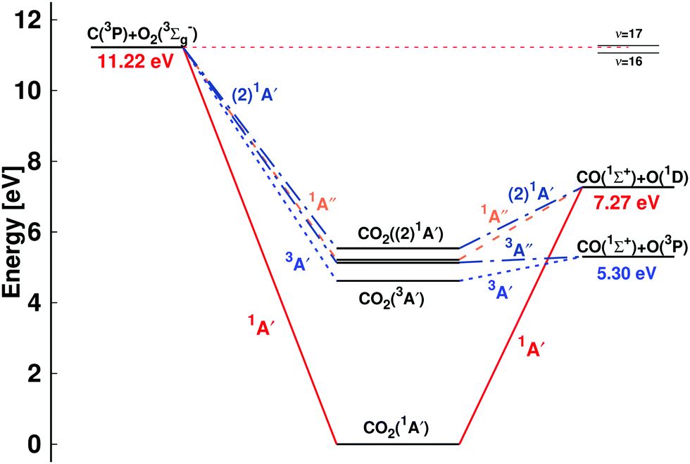 | ||
| Fig. 1 Energy level diagram for the C + O2 ↔ CO + O reaction: C(3P) + O2(3Σg−) ↔ CO(1Σ+) + O(3P) and C(3P) + O2(3Σg−) ↔ CO(1Σ+) + O(1D). The energies of the dissociating species are reported: the O(1D)/O(3P) separation is 1.97 eV, consistent with experiment, and the total energies for CO2 are 1A′ (1Σg in D∞h) (0 eV), 3A′ (4.62 eV), 3A′′ (5.14 eV), 1A′′ (5.22 eV), and (2)1A′ (5.53 eV). The relative positions of the CO (ν′ = 16) + O(1D) and CO (ν′ = 17) + O(1D) asymptotes, relevant for discussing the low energy collision C(3P) + O2(3Σg−) ↔ CO(1Σ+) + O(1D) reaction,34 are indicated on the right hand side. The correlation of the (2)1A′ state of CO2 based on state-averaged SA-CASSCF calculations given in Fig. S1 (ESI†) with the reactant and product state is consistent with earlier work8 but differs from others.13 | ||
Several independent studies have determined thermal rates for the forward C(3P) + O2(3Σg−) reaction.3–5 Using the CRESU (Cinétique de Réaction en Ecoulement Supersonique Uniforme) technique5 the thermal rate from experiments between 15 and 295 K was measured. At 298 K the rate was 4.8 ± 0.5 × 10⁻¹¹ cm3 molecule−1 s−1 which is within a factor of two to three of other, previous experiments.3,4,6,7 In all three laval nozzle experiments it was found that the rate increases with decreasing temperature between 15 and 295 K.5,8,9 The product detection techniques included vacuum ultraviolet laser-induced fluorescence,5,9 and chemiluminescence.8
Shock tube experiments of the C + O2 reactions were also carried out at higher temperatures (from 1500 to 4200 K) and reported a rate of kf(T) = 1.2 × 10¹⁴![[thin space (1/6-em)]](https://www.rsc.org/images/entities/char_2009.gif) exp(−2010 K/T) cm3 mol−1 s−1 (corresponding to 1.9 × 10⁻¹⁰exp(−2010 K/T) cm3 molecule−1 s−1) with an overall uncertainty of ±50% and a standard deviation for the activation energy of ±15% and ±13%, respectively.10 Yet earlier emission spectra in a discharge flow found that the C(3P) + O2(3Σg−) reaction generates CO in high vibrationally excited states (up to ν′ = 17) and that the transition state has the configuration COO rather than OCO.11 Such a COO intermediate was also proposed from the interpretation of the C + O2 reaction12 and has been described in multiconfiguration SCF calculations.13 Also, no evidence was found that the C + O2 reaction passes through the region where the quenching of O(1D) to O(3P) by CO occurs as a non-adiabatic process, as had been proposed earlier.14,15
exp(−2010 K/T) cm3 mol−1 s−1 (corresponding to 1.9 × 10⁻¹⁰exp(−2010 K/T) cm3 molecule−1 s−1) with an overall uncertainty of ±50% and a standard deviation for the activation energy of ±15% and ±13%, respectively.10 Yet earlier emission spectra in a discharge flow found that the C(3P) + O2(3Σg−) reaction generates CO in high vibrationally excited states (up to ν′ = 17) and that the transition state has the configuration COO rather than OCO.11 Such a COO intermediate was also proposed from the interpretation of the C + O2 reaction12 and has been described in multiconfiguration SCF calculations.13 Also, no evidence was found that the C + O2 reaction passes through the region where the quenching of O(1D) to O(3P) by CO occurs as a non-adiabatic process, as had been proposed earlier.14,15
For the reverse reactions, O(3P) + CO(1Σ+), and O(1D) + CO(1Σ+) leading to C(3P) + O2(3Σg−), the onset for the rates kr(T) to form C + O2 is expected to occur at considerably higher temperature than that for kf due to the large energy difference of ∼6 eV between the O + CO and the C + O2 asymptotes, see Fig. 1. There are, however, computational investigations of the oxidation of CO to form CO2 following the O(3P) + CO(1Σ+) → CO2(1Σg+) route, usually involving a third particle M.16 The rates for formation of CO2 along the 3A′ and 3A′′ pathways starting from O(3P) + CO(1Σ+) ranged from 10−13 to 10−12 cm3 molecule−1 s−1, depending on temperature, compared with ∼10−14 cm3 molecule−1 s−1 from earlier work.17 These were non-Born–Oppenheimer dynamics simulations of the O(3P) + CO(1Σ+) → CO2(1Σg+) reaction involving the 1A′, 3A′, and 3A′′ potential energy surfaces (PESs).16 The spin-forbidden fraction in this study was, however, found to be small (∼1%). Experimentally, the forward reaction has not been probed so far, to the best of our knowledge. Direct experiments involving [O(3P), O(1D)] and CO(1Σ+) concern the vibrational deactivation of CO upon collision with atomic oxygen.2,18–21 Finally, the rate for the O(1D) to O(3P) spin relaxation by CO(1Σ+) at temperatures between 113 and 333 K was determined.22 The rates were found to vary monotonically from about 7.6 × 10⁻¹¹ to 5.2 × 10⁻¹¹ cm3 molecule−1 s−1 over the temperature range. Earlier modeling based on collisions with CO and other small molecules obtained a rate of 8 × 10⁻¹¹ cm3 molecule−1 s−1.23
Computationally, the ground and excited state PESs for CO2 have been studied in some detail.13,24–29 Early configuration interaction calculations established24 that there must be four states (two singlet and two triplet) of CO2 below the CO(1Σ+) + O(3P) asymptote which is also what is found in the present work (Fig. 1). CO2 does not show strong absorptions below 11 eV24 which makes direct comparison difficult also, because often vertical and not adiabatic transition energies were measured. A low-lying adiabatic electronic transition to a triplet state was reported at 39412 cm−1 (4.89 eV) above the ground state,30 in qualitative agreement with the position of the 3A′ state, 4.62 eV above the ground state, see Fig. 1.
An early classical MD study31 of the forward reaction using an analytical potential energy surface found a rate of kf = 1.92 × 10⁻¹¹ cm3 molecule−1 s−1. In dynamics studies16,18,28,32,33 the reference energies from electronic structure calculations were either represented as parametrized fits,18,32,33 cubic splines,28 or interpolated moving least squares.16 Reference calculations were carried out at the CASSCF-MP2/631G+(d),18 and MRCI+Q/aug-cc-pVQZ levels of theory.16,28,33 The dynamics simulations either concerned the O-induced collisional dissociation of CO,33 CO vibrational relaxation,18 the O-exchange dynamics in reactive O + CO collisions, non-Born–Oppenheimer effects in CO2 formation from O + CO collisions,16 or the final state distributions from the O + CO reactive scattering32 but not the entire C(3P) + O2(3Σg−) ↔ CO2 ↔ CO(1Σ+) + O(1D)/O(3P) reaction involving several electronic states.
A schematic of the states derived from the present calculations and considered in the present work is provided in Fig. 1. The left hand side is the C(3P) + O2(3Σg−) (entrance) channel which connects to all bound CO2 states in the middle. This asymptote is 11.22 eV above the global minimum which is the linear CO2(1A′) structure. The right hand side of Fig. 1 shows the two product channels considered: the lower CO(1Σ+) + O(3P) state, 5.30 eV above the minimum energy of the CO2(1A′) ground state, and the CO(1Σ+) + O(1D) asymptote another 1.97 eV higher in energy. The final state involving O(3P) connects with the triplet states (3A′ and 3A′′) of CO2 whereas that leading to O(1D) correlates with the 1A′, 1A′′, and (2)1A′ states, see Fig. 1.
Except for the shock tube experiments35 on C + O2 → O + CO (1500–4200 K) and the computations16 for CO2 formation from O + CO (between 1000 K and 5000 K) there is little information on the high-temperature dynamics of either, the C + O2 or the O + CO reactive processes. The present work extends this by performing QCT simulations on the 5 lowest states of CO2, represented as a reproducing kernel Hilbert space (RKHS),36,37 and focusing on the forward and reverse reactions and vibrational relaxation. First, the methods are presented and the potential energy surfaces for all 5 states are discussed. Then the thermal rates are determined along the singlet pathway. Next, vibrational relaxation for the O + CO collision is considered for CO(ν = 1) and CO(ν = 2) and the distributions for relaxing/nonrelaxing reactive/nonreactive trajectories are mapped onto the PES. Finally, conclusions are drawn.
Computational methods
This section presents the generation and representation of the potential energy surfaces and the methodologies for the QCT simulations and their analysis.Electronic structure calculations
All PESs are computed at the multi reference CI singles and doubles (MRCISD) level of theory38,39 including the Davidson quadruples correction40 (MRCISD+Q) together with the aug-cc-pVTZ basis set41 using the MOLPRO 2019.1 software.42 In order to consistently describe all relevant states and avoid numerical instabilities due to closely-lying states of the same symmetry, state-averaged CASSCF43–46 calculations including the two lowest states of each symmetry (two spin symmetries and two spatial symmetries) were carried out. Hence, in total eight states are included in the CASSCF reference wave function. MRCISD+Q calculations for both asymptotic channels followed for the 5 lowest CO2 states, namely 1A′, 3A′, 3A′′, 1A′′, and (2)1A′, see Fig. 1.The energies were computed on a grid defined by Jacobi coordinates (r,R,θ) where r is the separation of the diatomic, R is the distance between the atom and the center of mass of the diatomic and θ is the angle between the two unit vectors ![[r with combining right harpoon above (vector)]](https://www.rsc.org/images/entities/i_char_0072_20d1.gif) and
and ![[R with combining right harpoon above (vector)]](https://www.rsc.org/images/entities/i_char_0052_20d1.gif) . For channel I (C(3P) + O2(3Σg−)) the R-grid included 28 points between 1.4 and 11a0 and the distance r was covered by 20 points between 1.55 and 4.10a0 whereas for channel II (O(3P/1D) + CO(1Σ+)) the R-grid included 26 points between 1.8 and 11a0, and the distance r was covered by 20 points between 1.55 and 4.00a0. The angular grid for both channels contained 13 angles from a Gauss–Legendre quadrature (169.796°, 156.577°, 143.281°, 129.967°, 116.647°, 103.324°, 90.100°, 76.676°, 63.353°, 50.033°, 36.719°, 23.423°, 10.204°).
. For channel I (C(3P) + O2(3Σg−)) the R-grid included 28 points between 1.4 and 11a0 and the distance r was covered by 20 points between 1.55 and 4.10a0 whereas for channel II (O(3P/1D) + CO(1Σ+)) the R-grid included 26 points between 1.8 and 11a0, and the distance r was covered by 20 points between 1.55 and 4.00a0. The angular grid for both channels contained 13 angles from a Gauss–Legendre quadrature (169.796°, 156.577°, 143.281°, 129.967°, 116.647°, 103.324°, 90.100°, 76.676°, 63.353°, 50.033°, 36.719°, 23.423°, 10.204°).
The reference points are then represented using reproducing kernel Hilbert space (RKHS) techniques.36,37,47 The quality of the representation is further checked using energies from additional, off-grid geometries. The global, reactive 3D PES V(r1,r2,r3) for an electronic state is constructed by summing the weighted individual PESs for each channel
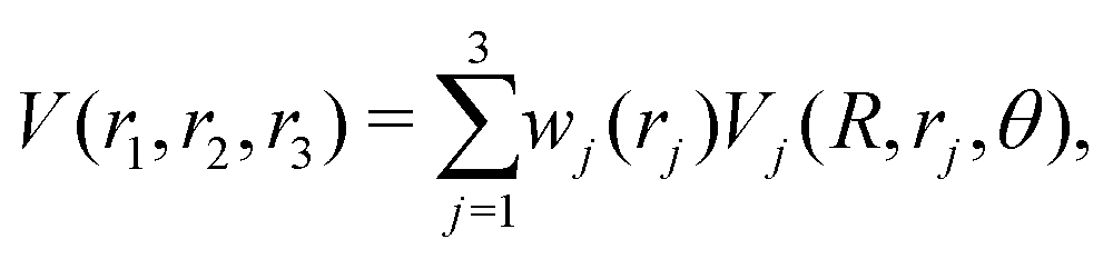 | (1) |
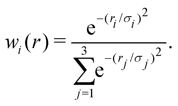 | (2) |
The global and local minima and transition states between the minima and/or entrance channels supported by the PESs were determined using BFGS minimization and the nudged elastic band method48 as implemented in the atomic simulation environment (ASE).49
Quasi-classical trajectory simulations
The QCT simulations used in the present work have been extensively described in the literature.50–53 Here, Hamilton's equations of motion are solved using a fourth-order Runge–Kutta method. The time step was Δt = 0.05 fs which guarantees conservation of the total energy and angular momentum and the initial separation of the reactants was 19a0. Fig. S2 (ESI†) reports reference energies from electronic structure calculations (open symbols) with the resulting RKHS PES for a given angular cut out to a distance of r = 40a0. The maximum impact parameter bmax was 15.0a0 (at low T and for low collision energy) and was reduced to 8.0a0 for rate calculations at the highest temperatures. Initial conditions for the trajectories are sampled using standard Monte Carlo methods.50 The reactant and product ro-vibrational states are determined following semiclassical quantization with quantum bound state calculations for the two diatomics. Since the ro-vibrational states of the product diatom are continuous numbers, the states need to be assigned to integer values for which a Gaussian binning (GB) scheme was used. For this, Gaussian weights centered around the integer values with a full width at half maximum of 0.1 were used.52,54,55 It is noted that using histogram binning (HB) was found to give comparable results for a similar system.53The thermal rate for an electronic state (i) at a given temperature (T) is then obtained from
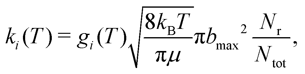 | (3) |
For the forward C(3P) + O2(3Σg−) → CO(1Σ+) + O(1D) and reverse reactions CO(1Σ+) + O(1D) → C(3P) + O2(3Σg−) with rates kf(T) and kr(T), respectively, the degeneracy factor is
 | (4) |
 . From kf(T) and kr(T) the equilibrium constant
 | (5) |
Results
The potential energy surfaces
Two-dimensional contour plots of the PESs are shown in Fig. 2 and the positions and relative energies of the critical points are summarized in Table 1. The left hand column in Fig. 2 reports the PESs for the C + O2 asymptote whereas the right hand column that for the CO + O channel, including the linear ground state structure for CO2 (Fig. 2b). All PESs for the C + O2 asymptote are manifestly symmetric with respect to θ = 90° with moderate anisotropies for the 1A′ and 3A′ states and increased anisotropies for all other PESs. Conversely, all PESs for the O + CO channel are single-minima PESs with their minima around 140°, except for the 1A′ state which has a minima for the OCO (180°) and OOC (0°) structures, see also Fig. S3 (ESI†). The energy of the OOC state is 170.0 kcal mol−1 (7.37 eV) above the OCO minimum and the barrier height for transition between the OOC and OCO minima is 8.5 kcal mol−1 (0.369 eV). In addition, the existence of the local OOC minimum was confirmed at the MRCISD+Q and CCSD(T) levels of theory and was suggested earlier from experiments11,12 and calculations.13 | ||
| Fig. 2 Two-dimensional cuts through the 3-d PES for the OO + C (left) and the CO + O (right) channels. Energy contours (in eV) for the 1A′ (panels a and b), 3A′ (panels c and d), 3A′′ (panels e and f), 1A′′ (panels g and h), and (2)1A′ (panels i and j) states. The OO and CO diatomic distance are fixed at r = 2.14 and r = 2.29a0 for the CO + O and OO + C channels, respectively. The zero of energy is the dissociation into atomic fragments (C(3P) + O(3P) + O(3P)). The symbol (“+”) indicates local and global minima on each PES. | ||
| PES | Present work | Literature16,18,57–59 | ||||||
|---|---|---|---|---|---|---|---|---|
| r 1 (COA) | r 2 (COB) | ∠(OCO) | E (eV) | r 1 | r 2 | ∠(OCO) | E (eV) | |
| (2)1A′ MIN | 2.368 | 2.368 | 119.0 | 0.23 | — | — | — | — |
| 1A′′ MIN | 2.374 | 2.374 | 130.5 | −0.13 | — | — | — | — |
| 3A′′ MIN | 2.374 | 2.374 | 130.6 | −0.14 | 2.364 | 2.364 | 127.2 | −0.23 |
| 2.399 | 2.399 | 127.0 | −0.22 | |||||
| 3A′′ TS | 2.165 | 3.431 | 135.8 | 0.47 | 2.147 | 3.515 | 126.2 | 0.35 |
| 2.192 | 3.496 | 122.0 | 0.30 | |||||
| 3A′ MIN | 2.356 | 2.356 | 126.3 | −0.69 | 2.381 | 2.381 | 118.0 | −0.94 |
| 2.349 | 2.349 | 118.0 | −0.92 | |||||
| 3A′ TS | 2.163 | 3.544 | 116.3 | 0.39 | 2.143 | 3.628 | 120.8 | 0.28 |
| 2.192 | 3.779 | 112.0 | 0.20 | |||||
| 1A′ (Global-M) | 2.206 | 2.206 | 180.0 | −5.30 | 2.196 | 2.196 | 180.0 | −5.45 |
| 2.194 | 2.194 | 180.0 | −5.64 | |||||
| 1A′ (MIN1) | 2.527 | 2.527 | 70.6 | 0.74 | 2.522 | 2.522 | 72.9 | 0.61 |
| 1A′ (MIN2) | 2.192 | 4.798 | 0.0 | 1.88 | 2.220 | 4.716 | 0.0 | 1.72 |
| 1A′ (TS1) | 2.502 | 2.430 | 88.4 | 1.05 | 2.600 | 2.309 | 91.8 | 1.04 |
| 1A′ (TS2) | 2.164 | 4.279 | 68.9 | 2.15 | 2.203 | 4.537 | 41.0 | 2.22 |
The quality of the RKHS representations is reported in Fig. S4 (ESI†). All root mean squared errors for both, on-grid and off-grid points are below 1 kcal mol−1 (0.043 eV), except for the 1A′′ PES for which it is 1.04 kcal mol−1 (0.045 eV), all evaluated on the mixed PESs, see eqn (1) and (2). For the individual channels the performance of the RKHS is even better. One dimensional cuts for an OCO angle of 120° directly comparing the reference points and the RKHS are shown in Fig. S5 (ESI†) for the lowest five states. Importantly, for off-grid points which were not used to construct the PESs but to independently validate the RKHS representations, the RMSEs are all below 1 kcal mol−1 (0.043 eV), too.
For a better understanding of the shapes of the PESs, the SA-CASSCF/aug-cc-pVTZ wave functions were analyzed in more detail for the different states at a bent geometry (θ = 117.65°), see Fig. 3, for rCO = 2.14a0 and varying R. Fig. 3A shows the valence molecular orbitals that are relevant for the description of the eight states in the SA-CASSCF calculations along the CO2 → CO + O dissociation for this bent geometry. Fig. 3B depicts the dominant configuration state functions along this dissociation path. All states except for the energetically high lying (2)3A′ state resolve with one dominant CASSCF configuration state function for the eight computed states of SA-CASSCF and keep their characteristic configuration along the entire dissociation path. Hence, no avoided crossing of two states with the same symmetry is observed. Fig. 3C shows the relative energetics (taking the C(3P) + O(3P) + O(3P) ground state computed with the same level of theory as the reference).
 | ||
| Fig. 3 Analysis of the all-valence active space SA-CASSCF/aug-cc-pVTZ wave functions for a bent geometry with θ = 117.65°, rCO = 2.14a0 and for R = 2.4, 3.4, 4.4a0 (CO2 → CO + O dissociation path). (A) Valence molecular orbitals (natural orbitals) energetically close to the three frontier orbitals (red frames) whose occupation defines the five lowest lying electronic states considered for the dynamics on the CO2 PES. The three depicted geometries are oriented with the symmetry plane parallel to the paper plane. Orbitals symmetric and antisymmetric with respect to the plane in the left and right columns of each diagram, respectively. (B) Dominant configuration state functions of the eight states included in the SA-CASSCF calculation depicted as MO diagrams of the orbitals presented in panel A. If other configurations contributed with a weight >0.05, the orbitals involved in the entanglement are marked by an asterisk (i.e. these orbitals have an occupation number that deviates significantly from the depicted integer value). (C) Energy curves of the eight states for the CO2 → CO + O dissociation at this bent geometry. The ground state C + O + O energy computed at the same level of theory is the reference energy. | ||
Upon bending, the doubly degenerate π3 non-bonding [doubly occupied in 1A′], as well as the π3 antibonding [unoccupied in 1A′] orbitals for collinear CO2 undergo a splitting due to the lifted degeneracy. This results in a Jahn–Teller splitting of the states 1A′′, 3A′′, 3A′, and (2)1A′ of CO2 with their energy minimum at a bent geometry, see right hand column in Fig. 2. The splitting of the degenerate HOMO and LUMO π3 orbitals upon bending leads to three frontier orbitals, similar in energy, and with overall occupation of four electrons in all five energetically low-lying states (red frames in Fig. 3A). One of these three frontier orbitals has σ* character along the O–O bond (see Fig. 3A) and is somewhat higher in energy. States that involve double occupation of this orbital lie higher in energy. Along the same line, states that involve single occupation of one of the strongly bonding orbitals below the frontier orbitals also lie energetically higher.
The 3A′ and 3A′′ states are lower in energy than the 1A′ state for certain bent geometries (see Fig. 2 and 3C), as the triplet states gain from increased Pauli exchange, as well as reduced Coulomb repulsion due to the single occupations of orbitals. The corresponding open shell singlet states [(2)1A′ and 1A′′] lie slightly higher in energy than their triplet counterparts due to reduced Pauli exchange.
All CO2 singlet states connect to CO(1Σ+) + O(1D) upon dissociation whereas the 3A′, 3A′′, and (2)3A′′ states connect to the CO(1Σ+) + O(3P) state. On the other hand, the (2)3A′ connects to the energetically high-lying excited CO(3Π) + O(3P) state. The low-lying triplet CO2 states have no or rather low barriers towards their dissociation across the entire PES (see Fig. 2 and 3C). Specifically, the (2)3A′′ state connects to the ground state of CO + O and crosses the singlet states upon dissociation. The crossing should nevertheless only lead to negligible non-adiabatic transition rates, as they are spin-forbidden. Since this state involves double occupation of an orbital with σ* character of the O–O bond, it correlates with high lying excited states in the C + O2 channel and is energetically well separated from the 3A′′ state whenever there are short O–O distances. It is therefore sufficient to take its occupation only into account via the degeneracy of O(3P) in the quasi-classical treatment of the CO + O dissociation channel.
Forward and reverse rates and the equilibrium constants
The forward reaction C(3P) + O2(3Σg−) (Fig. 1) generates ground and excited state oxygen (3P and 1D). The pathway to yield 3P involves the 3A′ and 3A′′ CO2 PESs whereas that to form 1D goes through the 1A′, (2)1A′, and 1A′′ states. For each of the reactions on each PES a minimum of 5 × 10⁵ trajectories was run at each temperature.
Fig. 4 shows the total thermal rates for formation of O(1D) and O(3P). The rates for formation of O(1D) start at 1.72 × 10⁻¹⁰ cm3 molecule−1 s−1 at 15 K, drop to 5.19 × 10⁻¹¹ cm3 molecule−1 s−1 for T ∼ 600 K and then monotonically increase to 3.23 × 10⁻¹⁰ cm3 molecule−1 s−1 for higher temperatures, see red line for the total rate in Fig. 4 with explicit numerical values reported in Table S1 (ESI†) which also reports the number of reactive trajectories that contribute to the rate. Experimentally, the total rate for this process was determined over the temperature range from 1500 K to 4000 K.35 Evaluating the reported expression 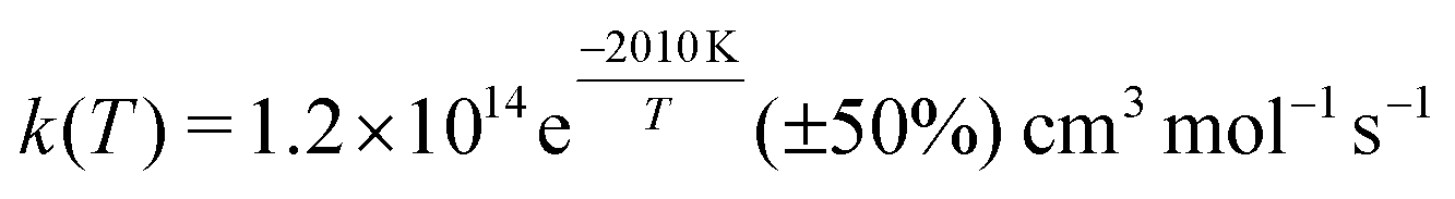 at 1500 K and 4000 K yields rates of k(1500) = 5.22 × 10⁻¹¹ cm3 molecule−1 s−1 and k(4000) = 1.21 × 10⁻¹⁰ cm3 molecule−1 s−1. This compares with k(1500) = 5.96 × 10⁻¹¹ cm3 molecule−1 s−1 and k(4000) = 1.05 × 10⁻¹⁰ cm3 molecule−1 s−1, respectively, from the present simulations. A high temperature measurement at 8000 K, associated with a substantial uncertainty, yields k ∼ 5 × 10⁻¹⁰ cm3 molecule−1 s−1.60
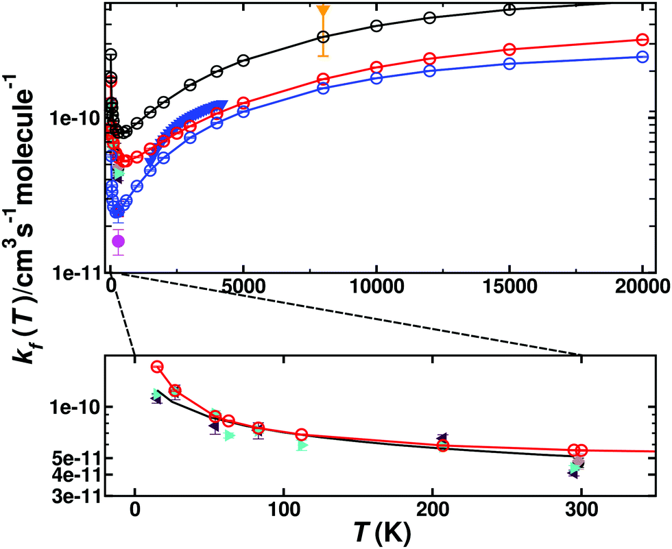 | ||
| Fig. 4 Thermal rate for the forward reaction (kf) C(3P) + O2(3Σg−) → CO(1Σ+) + O(1D)/O(3P). The sum of the contribution of the singlet (red circles) and triplet (blue circles) states and the total rate (black circles). Comparison with forward rates from experiments: ref. 35 (solid blue triangles) ref. 8 (solid green right triangle), ref. 7 (solid magenta circle), ref. 6 (solid black circle), ref. 4 (solid blue square), ref. 5 (grey diamond), ref. 60 (solid orange triangle down) and ref. 3 (red triangle). The bottom panel shows an enlarged view for 0 < T < 300 K for the total singlet rate (solid red line) together with the experimental results and a fit using Arrhenius parameters provided in the literature5 (inset, black solid line). | ||
The inset of Fig. 4 reports the low-temperature results. Starting at 15 K the rate first decreases, goes through a minimum (at ∼600 K) before it raises again for higher temperatures. Such a behaviour is indicative of a submerged barrier61 which, based on the rates for individual surfaces, appears to be dominated by the 1A′ and 3A′ states, as seen in Fig. S6 (ESI†). Compared with experiments all computed rates are within 2% to 20% at 50 K and 30% to 40% for ref. 9 and 4% to 30% at 300 K for ref. 5 which can be considered good agreement. For the process to yield O(3P) the individual rates from the contribution of both triplet PESs (3A′ and 3A′′) as well as the total weighted sum from the process to yield O(1D) and O(3P) are also reported in Fig. 4 (blue and black lines), with numerical values given in Table S2 (ESI†).
For the reverse reaction, CO(1Σ+) + O(1D)/O(3P) → C(3P) + O2(3Σg−), similar simulations were carried out. As this is an uphill process (Fig. 1), this channel only opens at higher temperature, see Fig. 5. The dynamics for CO(1Σ+) + O(1D) → C(3P) + O2(3Σg−) involves the 1A′, (2)1A′, and 1A′′ states (for numerical values see Table S3, ESI†), whereas that for CO(1Σ+) + O(3P) → C(3P) + O2(3Σg−) is related to the 3A′ and 3A′′ states, given in Table S4 (ESI†). Compared with the forward rates, those for the reverse reaction are typically 1 to 5 orders of magnitude smaller. The reverse rates starting from O(1D) are larger by 1 to 2 orders of magnitude at high T than those from O(3P) which is consistent with the Boltzmann-weighted energy difference for the two asymptotes.
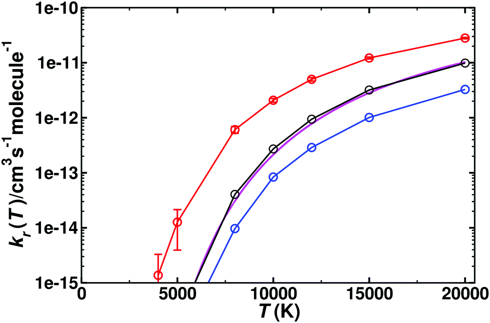 | ||
| Fig. 5 Thermal rate for the reverse (kr) reaction CO(1Σ+) + O(1D) → C(3P) + O2(3Σg−). The sum of the contributions of the singlet (red circles, with error bars from bootstrapping) and triplet (blue circles) states and their Boltzmann-weighted sum (black circles). The temperature range is from 5000–20000 K. Comparison with recent theoretical work33 (magenta solid line). | ||
Table 2 summarizes the parameters from fitting the raw data to a modified Arrhenius expression k(T) = ATnexp(−ε/T) for the forward and reverse processes for all five PESs. The temperature range covers 5000 to 20000 K as the CO(1Σ+) + O(1D) → C(3P) + O2(3Σg−) only opens above 5000 K. It is noted that all forward processes involve a comparatively small activation energy ε of a few hundred to a few thousand kelvin. All reverse rates have activation energies that are at least one order of magnitude larger. The number of trajectories that contribute to these rates varies from less than 1% to 55%. For the slowest process, the reverse reaction on the 3A′ and 3A′′ PESs originating from O(3P), at least an additional 5 × 10⁵ trajectories were run at each temperature between 3000 K and 20000 K and close to 106 trajectories for T ≤ 1000 K.
000 K
| Forward | A | n | ε |
|---|---|---|---|
| C(3P) + O2(3Σg−) → CO(1Σ+) + O(1D) | 4.12 × 10⁻¹² | 0.45 | 2209 |
| 1A′ | 2.42 × 10⁻¹² | 0.40 | 116 |
| (2)1A′ | 1.21 × 10⁻¹² | 0.47 | 4506 |
| 1A′′ | 1.06 × 10⁻¹² | 0.27 | 6639 |
| C(3P) + O2(3Σg−) → CO(1Σ+) + O(3P) | 3.50 × 10⁻¹¹ | 0.22 | 3513 |
| 3A′ | 1.60 × 10⁻¹¹ | 0.22 | 1891 |
| 3A′′ | 5.49 × 10⁻¹¹ | 0.11 | 6789 |
| Total | 1.56 × 10⁻¹¹ | 0.30 | 3018 |
| Reverse | |||
| O(1D) + CO(1Σ+) → C(3P) + O2(3Σg−) | 1.15 × 10⁻¹⁰ | 0.11 | 49965 |
| 1A′ | 1.25 × 10⁻¹² | 0.42 | 42273 |
| (2)1A′ | 4.60 × 10⁻¹² | 0.32 | 50111 |
| 1A′′ | 5.28 × 10⁻¹³ | 0.53 | 46836 |
| O(3P) + CO(1Σ+) → C(3P) + O2(3Σg−) | 1.52 × 10⁻¹² | 0.50 | 68903 |
| 3A′ | 8.92 × 10⁻¹⁴ | 0.70 | 64167 |
| 3A′′ | 7.80 × 10−09 | −0.37 | 83013 |
| Total | 1.55 × 10⁻¹⁰ | 0.09 | 71735 |
From the forward and reverse rates the equilibrium constant Keq(T) can also be determined, see Fig. 6. This equilibrium constant was determined from the total forward and reverse fluxes of the weighted sum of the singlet and triplet pathways according to the data summarized in Table 2. Error bars for the individual rates have been determined from bootstrapping and are compared with results determined from statistical mechanics. The equilibrium constant is only reported for temperatures 5000 K and higher as the reverse reaction only opens at these temperatures, see Fig. 5.
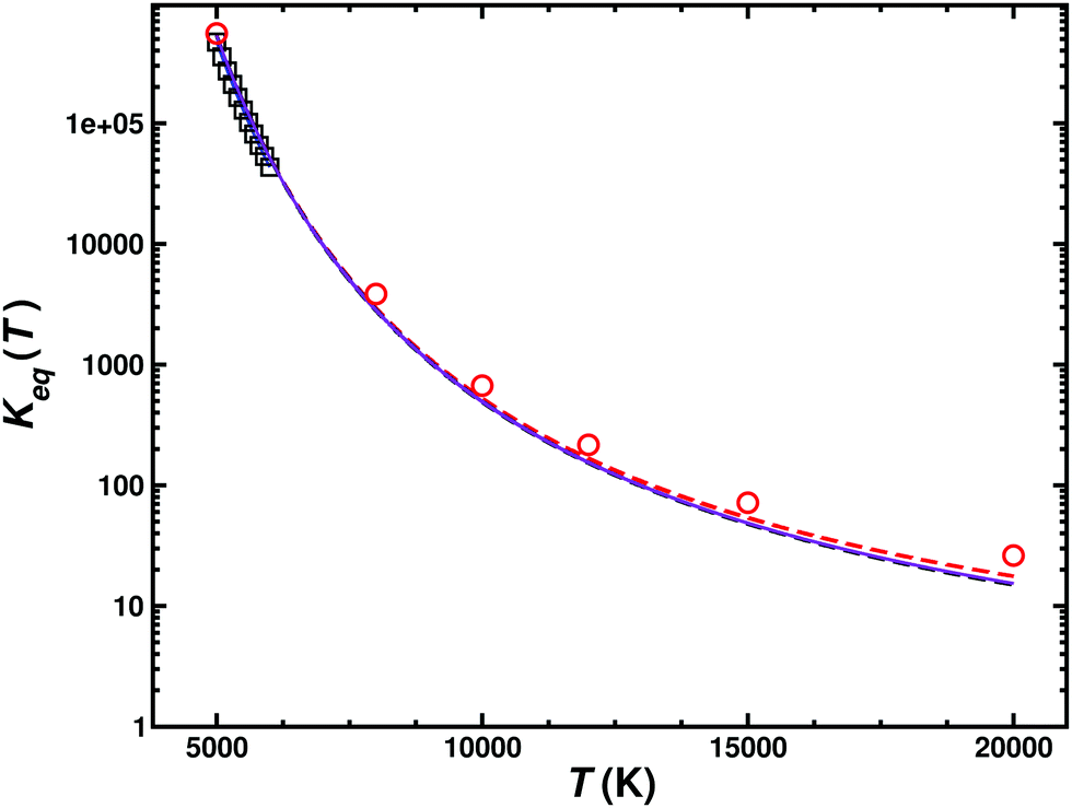 | ||
| Fig. 6 Equilibrium constant for the C(3P) + O2(3Σg−) ↔ CO(1Σ+) + O(1D1) (k1) and C(3P) + O2(3Σg−) ↔ CO(1Σ+) + O(3P) (k2) reactions. The results from the JANNAF tables62 (black open squares), those derived from equilibrium statistical mechanics (k1 (red open circles and red dashed line), k2 (black dashed line) and their Boltzmann-weighted total wk1 + (1 − w)k2 (purple solid line)) with those from the QCT simulations are compared. | ||
A final process considered is the atom exchange reaction COA(1Σ+) + OB(3P) → COB(1Σ+) + OA(3P). For this process, on the 3A′ state, rates ranging from 5 × 10⁻¹⁶ cm3 molecule−1 s−1 to 6 × 10⁻¹¹ cm3 molecule−1 s−1 between 500 K and 20000 K were found, see Table S5 and Fig. S7 (ESI†). The rate increases monotonically from values ∼10−16, consistent with those measured experimentally,63 as a function of T and is smaller than the measurement at 1820 K.64 One possible explanation is that this experimental value was an indirect measurement that required the decomposition rate for N2O and is presented without derived error bars. The barrier for the atom exchange reaction inferred from the low-temperature experiments is 6.9 kcal mol−1 (0.299 eV), which is also what is found from the present work (Fig. S8 and S9, ESI†).
A summary of all forward and reverse rates is provided in Fig. S6, and Tables S1–S5 (ESI†) report all numerical values for the temperature dependent rates.
Vibrational relaxation
Vibrational relaxation (VR) of CO in its ν = 1 and ν = 2 states was investigated for both, the singlet and triplet manifolds separately. VR was investigated by running 5 × 10⁵ trajectories at each temperature, ranging from 300 K to 5000 K, see Table S6 (ESI†). The final vibrational state was determined using Gaussian binning (GB) which has been shown to yield similar results as histogram binning.54,55,65Fig. 7 compares the individual and total VR rates with those measured experimentally and Table 3 reports the rates. Direct comparison with rates from Histogram binning shows that the two analyses yield a comparable T-dependence with rates from HB somewhat larger than those from GB. The computed rates are consistently lower than those from experiments at lower temperatures. For T > 2000 K the rates are in good agreement with experiments, though. In order to verify that the underestimation is not due to neglect of higher electronically excited states, the (2)3A′′ PES was also determined. This PES (not shown) is mainly repulsive. Therefore, the VR rates for this state only contribute ∼10% of the rates for the 3A′ and 3A′′ states at the highest temperatures. Hence, the differences between experiment and simulations at lower temperatures are not due to neglect of contributions from higher-lying electronic states (Table 3).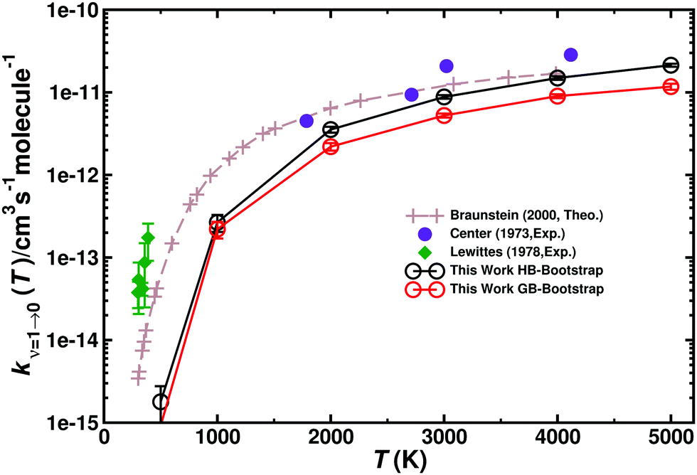 | ||
| Fig. 7 Total vibrational relaxation rate for O + CO(ν = 1) → O + CO(ν = 0). Total contribution (3A′ + 3A′′) (closed black circles) (g(e) = 1/3). Literature values are the symbols as indicated.2,18,20 5 × 10⁵ trajectories were run at every temperature. Open black circles from HB and open red circles from GB with error bars from bootstrapping. | ||
| 500 K | 1000 K | 2000 K | 3000 K | 4000 K | 5000 K | |
|---|---|---|---|---|---|---|
| 3A′ | 0.00 | 1.29 | 13.07 | 29.26 | 45.11 | 58.81 |
| 3A′′ | 0.00 | 0.87 | 8.97 | 22.70 | 43.87 | 57.21 |
| (2)3A′′ | 0.00 | 0.00 | 0.00 | 0.10 | 0.45 | 1.85 |
| Total | 0.00 | 2.16 | 22.05 | 52.06 | 89.42 | 117.87 |
In order to better characterize to which parts of the PESs the individual processes are sensitive to, density maps were determined as follows. For each initial condition a trajectory can be attributed to one of the 4 possible outcomes: (a) no vibrational relaxation, no reaction: O + CO(ν = 1) → O + CO(ν′ = 1) (b) vibrational relaxation without reaction: O + CO(ν = 1) → O + CO(ν′ = 0), (c) no vibrational relaxation but with atom exchange: OA + COB(ν = 1) → OB + COA(ν′ = 1), and (d) vibrational relaxation with atom exchange: OA + COB(ν = 1) → OB + COA(ν′ = 0). Then, all trajectories for a given class were combined and a 2-dimensional histogram was generated and smoothed using kernel density estimation (KDE).66 The resulting 2-dimensional distribution was then projected onto the relaxed PES for the corresponding state, see Fig. 8.
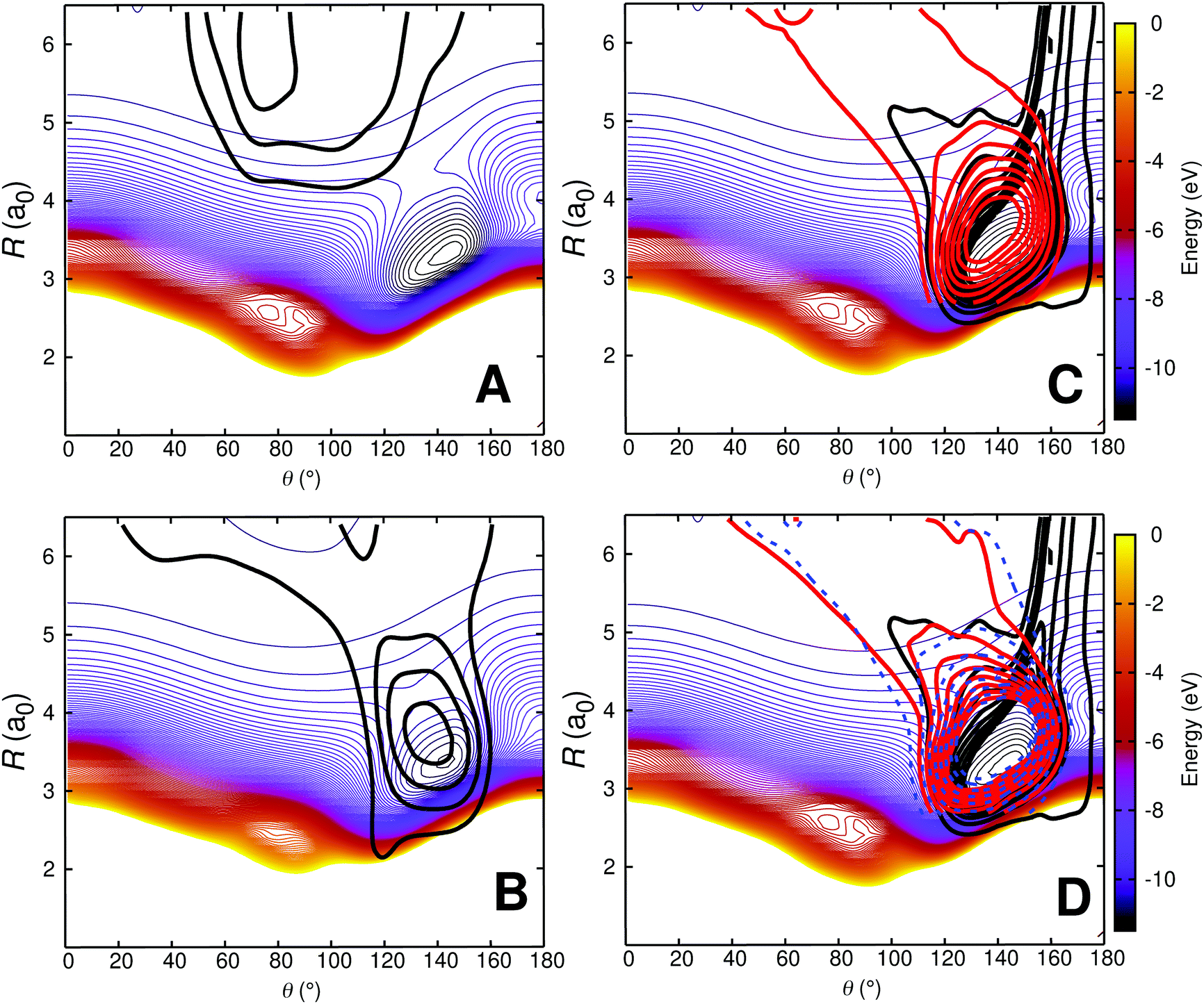 | ||
| Fig. 8 Density map for O + CO(ν = 1) collisions at 1000 K on the relaxed 3A′ PES. Panel A: O + CO(ν = 1) → O + CO(ν′ = 1); Panel B: O + CO(ν = 1) → O + CO(ν′ = 0); Panel C: OA + COB(ν = 1) → OB + COA(ν′ = 1) and Panel D: OA + COB(ν = 1) → OB + COA(ν′ = 0). For the reactive trajectories (panels C and D), two coordinate systems are used: one for the reactant (black density) in which the COB diatom is the distance r and the separation of atom OA from the center of mass is the distance R; the second coordinate system is for the product state (red density) for which the COA diatom is the distance r′ and the separation of atom OB from the center of mass is the distance R′. The dashed blue isocontours in panel D are for OA + COB(ν = 1) → OB + COA(ν′ = 2). The density map for the trajectories is superimposed on a relaxed 2D RKHS PES where 2.00 < r < 2.30a0 (turning points). For all density maps 1500 trajectories were used to generate the 2d densities which were smoothed using kernel density estimation (KDE) as implemented in the R software package.67 | ||
Fig. 8A shows that nonrelaxing trajectories sample regions in the long range without penetrating into the strongly interacting region around (R = 3.2a0, θ = 150°). Contrary to that, nonreactive, relaxing trajectories of the type O + CO(ν = 1) → O + CO(ν′ = 0) access the strongly interacting region and sample it before leaving this region again, see Fig. 8B. For the reactive trajectories (OA + COB → OB + COA), see Fig. 8C and D, all trajectories enter the strongly interacting region along θ ∼ 160° (black density).
After the reaction, the product (COA) can either remain vibrationally excited (Fig. 8C; no relaxation), or its vibrational state can change (COA(ν′ = 0) or COA(ν′ = 2)). The highest vibrational state in the products after reaction in these trajectories (run at 1000 K) is ν′ = 3. The probability distributions of the products from reactive collisions in Fig. 8C and D are in red (for ν′ = 0, relaxation) and in blue (for ν′ = 2, further excitation). The shape of the red and blue probability distributions in Fig. 8C and D can already be anticipated from the relaxed PES for the CO + O channel, see Fig. S10 (ESI†). Starting from around the minimum on the PES at (R = 3.2a0, θ = 140°) these densities follow the path indicated by the green isocontour at −10.5 eV in Fig. S10 (ESI†) through the constriction indicated as a red cross. A different perspective that could be taken is to refer to all reactive trajectories as “vibrationally relaxing” because the quanta initially present in COB are destroyed upon dissociation of COB. However, experimentally, the final states COB(ν′ = 1) and COA(ν′ = 1) can not be distinguished. Hence separation into 4 separate cases is meaningful in analyzing the trajectories.
It is also of interest to consider the distribution of contact times τc for each of the scenarios. This quantity was taken as the first instance along the trajectory for which the sum σ of all three atom distances is smaller than 12a0 in the entrance channel until the point at which σ > 12a0 along the exit channel. This was done for CO initially in its ν = 1 and ν = 2 states, respectively. The average contact times are reported in Table 4 and their distributions are shown in Fig. 9. It should, however, be noted that the average τc only incompletely characterize the underlying distribution P(τc) because the distributions are either structured (Fig. 9a and c) or extend to times more than 10 times the most probable value as in Fig. 9b and d.
| Relaxing | Nonrelaxing | ||||
|---|---|---|---|---|---|
| ν = 2 → 1 | ν = 2 → 0 | ν = 1 → 0 | ν = 2 → 2 | ν = 1 → 1 | |
| Reacting | |||||
| N | 300 | 230 | 679 | 340 | 742 |
| τ c | 210 | 207 | 333 | 241 | 301 |
| Non-reacting | |||||
| N | 480 | 440 | 1577 | 65788 |
117365 |
| τ c | 126 | 158 | 156 | 33 | 36 |
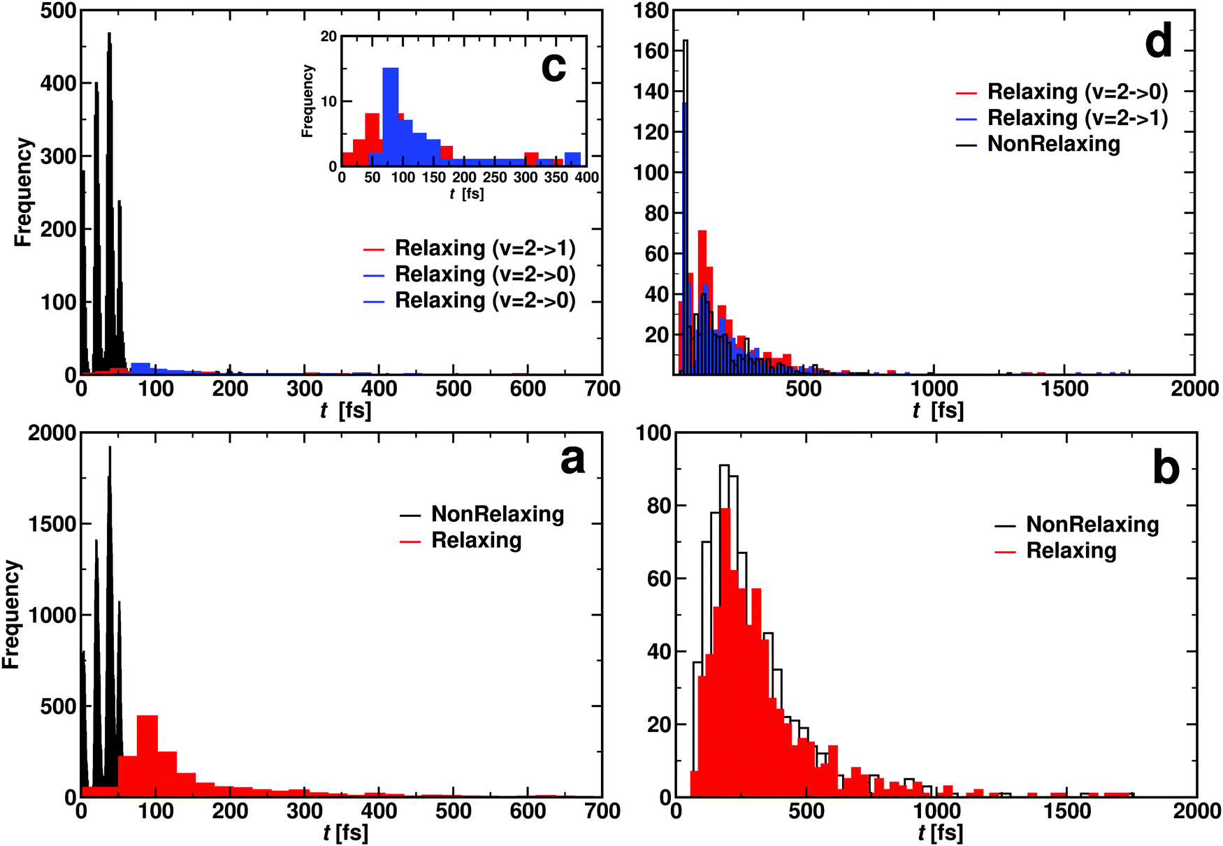 | ||
| Fig. 9 Contact time histogram for OA + COB → OB + COA (reacting: panel a and c) and OA + COB → OA + COB (non reacting: panel b and d). Bottom panels for CO(ν = 1) and top panel for CO(ν = 2). Panel c inset illustrates that relaxing two quanta (ν = 2 → 0, blue distribution) takes longer than relaxing one quantum (ν = 2 → 1, red distribution). Additional analysis of the data from panel c is provided in Fig. S11 (ESI†). Rates for the atom exchange reaction are given in Table S5 (ESI†). | ||
For reacting trajectories and non-reacting but relaxing trajectories, the contact time τc decreases with increasing vibrational excitation. This differs for non-reacting, relaxing trajectories. Their average contact times appear to be determined by the final vibrational state. For relaxation to ν′ = 0 the average vibrational relaxation time is ∼150 fs which shortens to ∼70 fs for relaxation to ν′ = 1 with initial ν = 2. This is in contrast to the non-relaxing non-reacting trajectories which appear to be independent of vibrational excitation. The τc for these trajectories is of the order of 30 fs which is roughly the minimum time required for one collision.
When considering the lifetime distributions it is found that those involving reacting trajectories display a regular pattern of peaks, see Fig. 9a and c. The specific case for relaxation from (ν = 1) → (ν′ = 0) is shown in Fig. S11 (ESI†). It is noticeable that the probability to find trajectories that react but do not relax P(τc) can be zero and reaches maximal values for other values for the lifetime. Fourier transformation of this signal yields frequencies between 1824 cm−1 and 2529 cm−1, see Fig. S11 (ESI†). These frequencies, which are in the range of typical CO stretch frequencies, can be understood as “gating modes” that allow the reaction to occur, similar to what was found for proton transfer in protonated ammonia dimer.68
It is also of interest to consider the geometries sampled for the C + O2→ CO + O(1D) reaction on the 1A′ PES depending on the temperature from which the initial conditions were generated. This was done for T = 15 K and T = 10000 K. For reactive trajectories at low temperature the global minimum is extensively sampled (see Fig. S12A, ESI†) whereas at high temperature this region is not sampled at all as shown in Fig. S12B (ESI†). Hence, collisions at different temperatures are expected to sample complementary regions of the 3d PES.
Discussion and conclusions
The present work reports thermal and vibrational relaxation rates from QCT simulations on the five lowest PESs of the [COO] system. Comparison of the computed rates with experiment is favourable for thermal rates and vibrational relaxation rates at high temperatures. For the atom exchange rate, agreement is rather more qualitative, with an overall offset in the energetics of 300 K (0.026 eV). Additional analyses are carried out in the following to provide an understanding of remaining disagreements between experiment and simulations.One interesting comparison can be made with state-to-state cross section measurements for the C(3P) + O2(3Σg−) ↔ CO(1Σ+) + O(1D) reaction at small collision energies.34 These experiments used a pulsed nozzle through which the O2 expanded into the vacuum. The O2 internal state distribution was not measured directly but expected to be very cold.34 Hence, it is likely that mostly O2(ν = 0) with low jmax was populated. Such experiments found that excitation of CO(ν′ = 16) occurs for all collision energies Ec whereas population of CO(ν′ = 17) is only possible with an excess of Ec > 0.04 eV. Using bound state energies for CO derived from experiment69 and accounting for the 0.04 eV required to open the CO(ν′ = 17) channel, the energy difference between CO(ν = 0) and CO(ν′ = 17) is 4.037 eV. Including zero point energy for CO and O2, the difference between the C(3P) + O2 and CO + O(3P) channels from experimental data is 4.075 eV. This differs by 0.085 eV from the value at the MRCISD level of theory which is 3.990 eV.
From semiclassical calculations on the present PESs the CO(ν′ = 17) state is at 4.140 eV. This compares with the difference in electronic energies (3.990 eV) and differences in the CO and O2 zero point energies of 3.952 eV. Hence, Ec = (4.140 − 3.952) = 0.188 eV is required to open the CO(ν′ = 17) channel. QCT simulations starting from Boltzmann-distributed (v,j) initial conditions generated at T = 2000 K find that the population of the CO(ν′ = 16) decays exponentially with increasing Ec (Fig. S13, ESI† left panel) which is consistent with experiments.34 Because expansion through a nozzle does not necessarily yield Boltzmann-distributed initial conditions and the experimental beam was deemed “very cold”,34 the final state distributions were also separated into those originating from O2(ν = 0) (open circles in Fig. S13, ESI†) and those from O2(v > 0) (solid line in Fig. S13, ESI†). For CO(ν′ = 16) all distributions follow the same overall behaviour.
Conversely, for CO(ν′ = 17) considering the final state distribution from initial O2(ν = 0) has an onset at ∼0.05 eV (inset Fig. S13, ESI† right panel) with a dependence on Ec consistent with experiment34 whereas including all initial v-states for O2 and those starting from O2(v > 0) again show a decaying probability distribution with increasing Ec. Because both, initial v and j are probably “cold”, it is meaningful to consider final CO(ν′ = 17) distributions originating from different jmax values for the parent O2 molecule. With decreasing jmax the CO(ν′ = 17) channel opens with increasing values of Ec. For  , the onset occurs at 0.05 eV and shifts to ∼0.15 eV for
  , which is consistent with the estimate of 0.188 eV based entirely on energetic arguments above. A temperature of T = 300 K corresponds to O2(j = 12) but the corresponding (nonequilibrium) distribution probably extends to higher j-values. Hence an estimated onset of generating CO(ν′ = 17) for Ec ∈ [0.05, 0.10] eV is expected from the present simulations. This corresponds to a difference of 0.01 eV to 0.06 eV from experiment on a scale of 4 eV, which is an error of 1% at most.
For the deactivation of O(1D) to O(3P) in the atmosphere early models performed well for the observed data available at that time.23 Carbon monoxide was categorized as a case that is dominated by the configuration of a critical region where a crossing between the single PESs originating from the O(1D) channel cross the triplet PESs leading to O(3P). For the crossing dynamics a Landau–Zener model was assumed. This simple approach lead to a predicted rate of 8.0 × 10⁻¹¹ cm3 molecule−1 s−1 at 300 K which was within the error of experimental measurements of 7.6 and 7.3 × 10⁻¹¹ cm3 molecule−1 s−1.14,70 Following this, the deactivation of O(1D) by CO was measured22 and the rate obtained was fit by the expression (4.7 ± 0.9) × 10−11exp((126 ± 33)/RT) (with E in cal mole−1) which yields a rate of 5.8 × 10⁻¹¹ cm3 molecule−1 s−1 at 300 K. Assuming ∼5 × 10⁻¹⁰ cm3 molecule−1 s−1 for the collision rate, this implies a ≈10% efficiency for deactivation of O(1D) to O(3P) at 300 K. Based on this low efficiency, crossing between the singlet and triplet manifolds are not expected to have a large impact on the formation, exchange or relaxation of the reaction.
As Tully pointed out,23 deactivation depends on the specific crossing geometry of the PESs; in this case the singlet and triplet surfaces. Fig. S14 and S15 (ESI†) show the crossings of the 3A with the 1A surfaces on PESs evaluated at the inner (Fig. S14, ESI†) and outer (Fig. S14, ESI†) turning points for the CO(ν = 0) vibration. When starting from the COA + OB side of the reaction, as was previously mentioned, Fig. 8 shows that the active reactions sample a channel near 140° that brings the outgoing OA atom into approximately R = 3.5a0. At low temperature, starting from CO + O(3P), it would be possible to cross from any of the 3A surfaces onto the 1A′ surface to lead to ground state CO2. However, in a collisionless environment the complex will still have sufficient energy to return to the 1A′ PES and will have to cross with a 3A surface to leave as O(3P). This may affect vibrational energy transfer or the exchange reaction and may be the reason for the shifts in the onset seen between the experiment and QCT such as in Fig. 7 at low temperature. Starting from CO + O(1D) and traveling along the 1A′ surface crosses all 3A surfaces while the (2)1A′ and 1A′′ surfaces only cross the repulsive (2)3A′′ surface. At temperatures lower than that required to form C(3P) + O2 these trajectories can potentially cross on to the 3A surfaces and then return to the CO + O(3P) state although it would be at high CO vibrational state.
One finding of the present work is the role “gating” plays in the different processes considered here. For one, vibrational relaxation with atom exchange displays gating in the contact time distributions which hints at a time-dependent barrier in the [COO] collision complex. This is explicitly seen in the barriers for the COA(1Σ+) + OB(3P) → COB(1Σ+) + OA(3P) atom exchange reaction on the 3A′ PES (Fig. S9, ESI†). Depending on the phase of the CO vibration at which the impinging oxygen atom collides with the diatomic molecule, the barrier for formation of the collision complex is either high or low. Such processes are particularly susceptible to zero-point vibrational effects which can not be captured in QCT simulations. Specifically, the vibrational wavefunction does not produce the same spatial probability distribution at low v as the classical trajectory. This results in differences in sampling times for when the gate is open versus closed. The rates from QCT simulations should, therefore, underestimate the true rates, in particular at low temperatures. This is indeed found for vibrational relaxation, see Fig. 7 and for the atom exchange reaction S7 (ESI†). As the vibrational relaxation rates include both, processes with and without atom exchange, and the CO vibration-dependent barriers only affect trajectories with atom exchange, it is conceivable that vibrational relaxation without atom exchange is not affected by these effects.
Including zero-point effects is likely to improve the comparison between calculations and experiments. Furthermore, nonadiabatic effects may further improve comparison with experiment, in particular for the processes leading from CO2 to the O + CO asymptotes. Analysis of vibrational relaxation demonstrates that depending on the process considered (with or without reaction), different parts of the fully-dimensional PES are sampled. This is also true for reactions at low (15 K) and higher (1000 K) temperatures, respectively. Together with suitable information from experiment the underlying PESs could be further improved from techniques such as morphing71,72 or Bayesian inference.73
The wave function analysis for the SA-CASSCF reference of the CO2 → CO + O dissociation channel, rationalizing the topography of this region of the PESs. No avoided crossings or conical intersections occur for the five lowest states along the dissociation for the bent CO2 geometry. The wave function analysis shows that the four lowest excited states of CO2 undergo a Jahn–Teller splitting caused by the splitting of the π system frontier orbitals upon bending of CO2. The five lowest electronic states arise then from different configuration state functions of four electrons in three frontier orbitals and rationalize the relative energy ordering of these states along the dissociation path for the bent geometry of CO2.
In conclusion, the present work provides a comprehensive characterization of the energetics and dynamics of the reactive [COO] system involving the lowest five electronic states. Many findings provide good agreement between simulations and experiments but it is also found that disagreements can be traced back to neglecting quantum mechanical effects at low temperatures. Additional experiments for this important system will provide a more complete understanding of the reactions involving both asymptotes.
Data availability
All information necessary to construct the potential energy surfaces is available at https://github.com/MMunibas/CO2-PESs.Conflicts of interest
There are no conflicts to declare.Acknowledgements
This work was supported by the Swiss National Science Foundation through grants 200020_188724 and the NCCR MUST, the AFOSR and the University of Basel.References
- M. Sharma, A. B. Swantek, W. Flaherty, J. M. Austin, S. Doraiswamy and G. V. Candler, J. Thermophys. Heat Transfer, 2010, 24, 673–683 CrossRef CAS
.
- M. E. Lewittes, C. C. Davis and R. A. McFarlane, J. Chem. Phys., 1978, 69, 1952–1957 CrossRef CAS
- D. Husain and A. N. Young, J. Chem. Soc., Faraday Trans. 2, 1975, 525–531 RSC
- A. Bergeat, T. Calvo, G. Dorthe and J. Loison, Chem. Phys. Lett., 1999, 308, 7–12 CrossRef CAS
- W. D. Geppert, D. Reignier, T. Stoecklin, C. Naulin, M. Costes, D. Chastaing, S. D. Le Picard, I. R. Sims and I. W. M. Smith, Phys. Chem. Chem. Phys., 2000, 2, 2873–2881 RSC
- K. H. Becker, K. J. Brockmann and P. Weisen, J. Chem. Soc., Faraday Trans. 2, 1988, 455–461 RSC
- G. Dorthe, P. Caubet, T. Vias, B. Barrere and J. Marchais, J. Phys. Chem., 1991, 95, 5109–5116 CrossRef CAS
- D. Chastaing, P. L. James, I. R. Sims and I. W. M. Smith, Phys. Chem. Chem. Phys., 1999, 1, 2247–2256 RSC
- D. Chastaing, S. D. Le Picard and I. R. Sims, J. Chem. Phys., 2000, 112, 8466–8469 CrossRef CAS
- A. J. Dean, D. F. Davidson and R. K. Hanson, J. Phys. Chem., 1991, 95, 183–191 CrossRef CAS
- E. Ogryzlo, J. Reilly and B. Thrush, Chem. Phys. Lett., 1973, 23, 37–39 CrossRef CAS
- J. Dubrin, C. MacKay, M. Pandow and R. Wolfgang, J. Inorg. Nucl. Chem, 1964, 26, 2113–2122 CrossRef CAS
- S. S. Xantheas and K. Ruedenberg, Int. J. Quantum Chem., 1994, 49, 409–427 CrossRef CAS
- R. F. Heidner, D. Husain and J. R. Wiesenfeld, Faraday Discuss., 1973, 69, 927–938 RSC
- R. Heidner and D. Husain, Nat. Phys. Sci., 1973, 241, 10–11 CrossRef CAS
- A. W. Jasper and R. Dawes, J. Chem. Phys., 2013, 139, 154313 CrossRef PubMed
- J. Troe, Fifth Symp. (Int.) Combust. 1975, vol. 15, pp. 667–679.
- M. Braunstein and J. W. Duff, J. Chem. Phys., 2000, 112, 2736–2745 CrossRef CAS
- P. Kozlov, V. Makarov, V. Pavlov and O. Shatalov, Shock Waves, 2000, 10, 191–195 CrossRef
- R. E. Center, J. Chem. Phys., 1973, 58, 5230–5236 CrossRef CAS
- J. D. Kelley and R. L. Thommarson, J. Chem. Phys., 1977, 66, 1953–1959 CrossRef CAS
- J. A. Davidson, H. I. Schiff, T. J. Brown and C. J. Howard, J. Chem. Phys., 1978, 69, 1216–1217 CrossRef CAS
- J. C. Tully, J. Chem. Phys., 1975, 62, 1893–1898 CrossRef CAS
- N. W. Winter, C. F. Bender and W. A. Goddard III, Chem. Phys. Lett., 1973, 20, 489–492 CrossRef CAS
- S. Y. Grebenshchikov and R. Borrelli, J. Phys. Chem. Lett., 2012, 3, 3223–3227 CrossRef CAS PubMed
- S. Y. Grebenshchikov, J. Chem. Phys., 2013, 138, 224107 CrossRef PubMed
- S. Y. Grebenshchikov, J. Chem. Phys., 2013, 138, 224106 CrossRef PubMed
- J. A. Schmidt, M. S. Johnson and R. Schinke, Proc. Natl. Acad. Sci. U. S. A., 2013, 110, 17691–17696 CrossRef CAS PubMed
- B. Zhou, C. Zhu, Z. Wen, Z. Jiang, J. Yu, Y.-P. Lee and S. H. Lin, J. Chem. Phys., 2013, 139, 154302 CrossRef PubMed
- R. N. Dixon and G. Porter, Proc. R. Soc. London, Ser. A, 1963, 275, 431–446 CAS
- S. Kinnersly and J. Murrell, Mol. Phys., 1977, 33, 1479–1494 CrossRef CAS
- A. L. Brunsvold, H. P. Upadhyaya, J. Zhang, R. Cooper, T. K. Minton, M. Braunstein and J. W. Duff, J. Phys. Chem. A, 2008, 112, 2192–2205 CrossRef CAS PubMed
- D. W. Schwenke, R. L. Jaffe and G. M. Chaban, NASA Tech. Rep, 2016, 1–56 Search PubMed
- M. Costes and C. Naulin, C. R. Acad. Sci., Ser. IIc: Chim., 1998, 1, 771–775 CrossRef CAS
- A. J. Dean, D. F. Davidson and R. K. Hanson, J. Phys. Chem., 1991, 95, 183–191 CrossRef CAS
- T.-S. Ho and H. Rabitz, J. Chem. Phys., 1996, 104, 2584 CrossRef CAS
- O. T. Unke and M. Meuwly, J. Chem. Inf. Model., 2017, 57, 1923–1931 CrossRef CAS PubMed
- H.-J. Werner and P. J. Knowles, J. Chem. Phys., 1988, 89, 5803–5814 CrossRef CAS
- P. J. Knowles and H.-J. Werner, Chem. Phys. Lett., 1988, 145, 514–522 CrossRef CAS
- S. Langhoff and E. Davidson, Int. J. Quantum Chem., 1974, 8, 61–72 CrossRef CAS
- T. H. Dunning, J. Chem. Phys., 1989, 90, 1007–1023 CrossRef CAS
-
H.-J. Werner; P. J. Knowles; G. Knizia and F. R. Manby; et al., M. S. MOLPRO, version 2019.1, A package of ab initio programs, 2019
- H.-J. Werner and P. J. Knowles, J. Chem. Phys., 1985, 82, 5053–5063 CrossRef CAS
- P. J. Knowles and H.-J. Werner, Chem. Phys. Lett., 1985, 115, 259–267 CrossRef CAS
- H.-J. Werner and W. Meyer, J. Chem. Phys., 1980, 73, 2342–2356 CrossRef CAS
- D. A. Kreplin, P. J. Knowles and H.-J. Werner, J. Chem. Phys., 2019, 150, 194106 CrossRef PubMed
- T.-S. Ho and H. Rabitz, J. Chem. Phys., 2000, 113, 3960–3968 CrossRef CAS
- G. Henkelman, B. Uberuaga and H. Jonsson, J. Chem. Phys., 2000, 113, 9901–9904 CrossRef CAS
- A. H. Larsen and J. J. Mortensen, J. Phys.: Condens. Matter, 2017, 29, 273002 CrossRef PubMed
-
D. G. Truhlar and J. T. Muckerman in Atom – Molecule Collision Theory, ed. R. B. Bernstein, Springer US, 1979, pp. 505–566 Search PubMed
-
N. E. Henriksen and F. Y. Hansen, Theories of Molecular Reaction Dynamics, Oxford, 2011 Search PubMed
- D. Koner, L. Barrios, T. González-Lezana and A. N. Panda, J. Phys. Chem. A, 2016, 120, 4731–4741 CrossRef CAS PubMed
- D. Koner, R. J. Bemish and M. Meuwly, J. Chem. Phys., 2018, 149, 094305 CrossRef PubMed
- L. Bonnet and J.-C. Rayez, Chem. Phys. Lett., 1997, 277, 183–190 CrossRef CAS
- L. Bonnet and J.-C. Rayez, Chem. Phys. Lett., 2004, 397, 106–109 CrossRef CAS
- J. E. Sansonetti and W. C. Martin, J. Phys. Chem. Ref. Data, 2005, 34, 1559–2259 CrossRef CAS
- NIST Chemistry WebBook, NIST Standard Reference Database Number 69.
- D.-Y. Hwang and A. M. Mebel, Chem. Phys., 2000, 256, 169–176 CrossRef CAS
- M. Braunstein and J. W. Duff, J. Phys. Chem. A, 2009, 113, 10795–10802 CrossRef CAS PubMed
- A. R. Fairbairn and A. G. Gaydon, Proc. R. Soc. London, Ser. A, 1969, 312, 207–227 CAS
- I. R. Sims, Nat. Chem., 2013, 5, 734–736 CrossRef CAS PubMed
- M. W. Chase, J. NIST-JANAF thermochemical tables, 4th edn, Washington, DC, American Chemical Society, New York, American Institute of Physics for the National Institute of Standards and Technology, 1998.
- S. Jaffe and F. S. Klein, Trans. Faraday Soc., 1966, 62, 3135–3141 RSC
- S. H. Garnett, G. B. Kistiakowsky and B. V. O Grady, J. Chem. Phys., 1969, 51, 84–91 CrossRef CAS
-
D. Koner, Scattering studies of proton transfer reactions between rare gas atoms, PhD thesis, Indian Institute of Technology Guwahati, 2016 Search PubMed
- E. Parzen, Ann. Math. Stat., 1962, 33, 1065–1076 CrossRef
- R. C. R. Team, A Language and Environment for Statistical Computing, R Foundation for Statistical Computing, Vienna, Austria, 2017.
- M. Meuwly and M. Karplus, J. Chem. Phys., 2002, 116, 2572–2585 CrossRef CAS
- S. Chandra, V. Maheshwari and A. Sharma, Astron. Astrophys., Suppl. Ser., 1996, 117, 557–559 CrossRef CAS
- W. Braun, R. L. Brown, D. Garvin, J. T. Herron, R. E. Huie, M. J. Kurylo, A. H. Laufer, J. D. McKinley, H. Okabe, M. D. Scheer, W. Tsang and D. H. Stedman, J. Phys. Chem. Ref. Data, 1973, 2, 267–312 CrossRef
- M. Meuwly and J. Hutson, J. Chem. Phys., 1999, 110, 8338–8347 CrossRef CAS
- J. M. Bowman and B. Gazdy, J. Chem. Phys., 1991, 94, 816–817 CrossRef CAS
- S. Venturi, R. L. Jaffe and M. Panesi, J. Phys. Chem. A, 2020, 124, 5129–5146 CrossRef CAS PubMed
Footnotes |
| † Electronic supplementary information (ESI) available. See DOI: 10.1039/d1cp01101d |
| ‡ Present Address: Department of Chemistry, Indian Institute of Science Education and Research (IISER) Tirupati, Karakambadi Road, Mangalam, Tirupati 517507, Andhra Pradesh, India. |
| This journal is © the Owner Societies 2021 |