 Open Access Article
Hydrogen adsorption trends on two metal-doped Ni2P surfaces for optimal catalyst design
Lauri
Partanen
 ,
Simon
Alberti
 and
Kari
Laasonen
 *
*
Department of Chemistry and Materials Science, Aalto University, P.O. Box 16100, FI-00076 Aalto, Finland. E-mail: kari.laasonen@aalto.f
First published on 28th April 2021
Abstract
In this study, we looked at the hydrogen evolution reaction on the doubly doped Ni3P2 terminated Ni2P surface. Two Ni atoms in the first three layers of the Ni2P surface model were exchanged with two transition metal atoms. We limited our investigation to combinations of Al, Co, and Fe based on their individual effectiveness as Ni2P dopants in our previous computational studies. The DFT calculated hydrogen adsorption free energy was employed as a predictor of the materials’ catalytic HER activity. Our results indicate that the combination of Co and Fe dopants most improves the catalytic activity of the surface through the creation of multiple novel and active catalytic sites.
1 Introduction
The steady increase in energy demand caused by technological advances and population growth is one of the principal challenges facing the scientific community.1–3 To exacerbate this issue, our reliance on fossil fuel combustion is unsustainable in the long run due to its limited availability and detrimental effects on the environment, climate, and human health.2,4 Hence, current energy research focuses on finding new clean, secure, and sustainable sources of energy.Viable large-scale energy alternatives to fossil fuels include nuclear and solar energies. For nuclear energy, long-term storage of highly toxic nuclear waste is an issue, as are the general risks associated with nuclear power plants.5 On the other hand, solar energy is only intermittently available and requires a long term storage solution. One possibility would be to store the energy chemically as hydrogen, which is abundant, lightweight, and produces only water upon oxidation.6 The large-scale conversion of energy to hydrogen could be accomplished by water-splitting through electrolysis. With this effective storage mechanism, solar energy could meet the global energy demand in an environmentally sustainable manner.
Electrochemical water-splitting consists of two parts: The hydrogen evolution reaction (HER) is a two-step process that takes place at the cathode, while the oxygen evolution reaction (OER) is a multistep process that occurs at the anode. Two HER pathways are normally considered, and the reaction mechanism depends on the pH of the electrolyte. Both mechanisms start with the Volmer reaction, where, in acidic conditions, the hydrogen first adsorbs on a surface site symbolised by *:
| H+(aq) + e− + * → *H. | (1) |
| *H + *H → H2(g) + 2*, | (2) |
| *H + H+(aq) + e− → H2(g) + *. | (3) |
Whether the reaction takes place in an alkaline or acidic medium, an efficient and cheap catalyst is required. Unfortunately, the best HER catalysts currently contain platinum, an exiguous noble metal.3 This is partly why large-scale hydrogen production through reactions (1), (2), and (3) is not economically feasible. Consequently, recent studies have looked at non-precious compounds as more convenient replacements for platinum, with examples ranging from heteroatom-doped nano-carbons to transition metal chalcogenides, nitrides, carbides, selenides, phosphides, borides, and sulfides.7–12 Particularly nickel phosphides have emerged as robust and efficient catalysts,13,14 showing advantages in terms of synthesis routes, anti-corrosion features, electronic properties, and catalytic activities – especially in the acidic medium.15–17
Once an efficient catalytic material like Ni2P has been identified, it is possible to further enhance its electrocatalytic performance through either morphological control or heteroatom doping.18 For example, transition metal doping of Ni2P structures by Mo,19 Al,20 Mn,21 W,22 V,23,24 Co,25–27 and Fe28–31 has already been experimentally verified to improve HER activity. Density functional studies have confirmed that the H-adsorption strength in the Volmer step depends on the microscopic structure of the surface and that dopants like Al, Mg, Cu, Co, Fe, Mo, and V can enhance the catalytic activity.32,33
Recently, experimentalists have begun to investigate the effect of incorporating multiple dopants on the Ni2P surface with promising results.31 To support these efforts, in this study, we consider the co-doping of the Ni2P surface by two of the metals Fe, Co and Al. These three metals were chosen based on their individual effectiveness as dopants in our previous DFT studies32,33 to keep the number of investigated surface structures manageable. We also manage the computational effort by using the broadly applied hydrogen adsorption free energy (ΔGH) model34–37 to evaluate the catalytic activity. In this model, ΔGH ≈ 0 between the electrode surface and a molecular H2(g) reference indicates optimal HER activity according to Sabatier's principle.36 As factors like the choice of the DFT functional can affect the ΔGH values,32 sites with |ΔGH| < 0.1 eV are considered optimal.36 We focus exclusively on the Ni3P2 termination of the (0001) Ni2P surface as it is the preferred bulk-like termination within the Ni2P stability region38,39 and is thought to be the active surface in Ni2P nanowires.40 Our main goals are to investigate how the combination of dopants alters the surface structure and how having multiple types of dopants impacts the HER activity of Ni2P.
2 Systems and methods
2.1 Computational details
All DFT calculations were performed using the CP2K/QUICKSTEP software.41,42 We made use of the Perdew–Burke–Ernzerhof (PBE) functional43 with the Kohn–Sham orbitals expanded in a molecularly optimised double-valence polarised basis set (MOLOPT-SR-DZVP) and the core electrons represented by the Goedecker–Teter–Hutter pseudopotentials (GTH).44–46 The plane-wave kinetic energy cutoff was set to 700 Ry, while the cutoff for the reference grid was 60 eV. Atomic positions were optimised with the force convergence criterion left to its default value of 0.023 eV Å−1. Periodic boundary conditions were used to solve the Poisson equation for the electrostatic potential.The Ni2P bulk lattice parameters were obtained by allowing a supercell of 4 × 4 × 4 unit cells to relax under a pressure tolerance of 0.1 kbar.32 This resulted in a nonferromagnetic end-state with cell parameters a = b = 5.860 Å, and c = 3.332 Å. To obtain the atomic reference energies of Ni, Fe, Co, and Al in the crystalline phase, we employed a supercell of 10 × 10 × 10 units with the PBE lattice parameters taken from the literature.47–49
While our original Ni2P calculation employed the orbital transformation method, the reference energy calculations used the diagonalisation method with the Fermi temperature set to 75 K. When we studied the effect of increasing this temperature to 300 and 400 K, the impact on the energy/atom was less than 0.02 eV in all cases.33
Our surface calculations used the same diagonalisation method as our atomic reference calculations with a 75 K electronic smearing but added the Grimme D3(BJ) dispersion corrections.50,51 We focused on the Ni3P2 termination of the (0001) Ni2P surface because it seems to be the active surface in Ni2P nanowires40 and also the preferred bulk-like termination in the Ni2P stability region.38,39 At around pH = 0, corresponding to the typical experimental conditions for HER in acid, this surface phase dominates at potentials U > −0.21 V vs. the standard hydrogen electrode.52 Below this region, both experimental and computational studies find that the surface becomes enriched by phosphorus.38,52–58 The resulting Ni3P2 + P termination then predominates within −0.21 V ≥ U ≥ −0.36 V. We chose not to include the Ni3P2 + P termination in this work because the pristine Ni3P2 + P surface is already such an efficient HER catalyst that it is difficult to detect any advantages of doping with the employed ΔGH model.33 Finally, for U <− 0.36 V, the pristine Ni3P2 surface becomes passivated by H atoms attaching to the Ni3 hollow sites.52
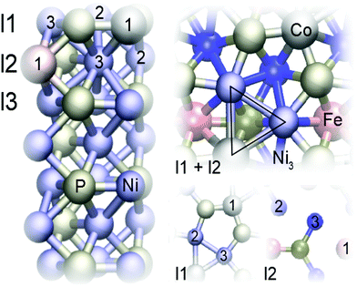
We modelled our surface with a seven-layer deep symmetric slab where the atoms at the bottom layer were fixed to their bulk positions.32 As illustrated in Fig. 1, the Ni3P2 terminated Ni2P surface has alternating Ni3P2 and Ni3P layers.59,60 Nanostructures such as terraces were not investigated. The dopant atoms were restricted to the top three layers, with only one dopant atom of each kind present in each surface. The notation (M1, M2)(lx1, lx2) is used to distinguish the surfaces, where xi is the layer of the dopant Mi with xi ∈ {1, 2, 3}. The positions within a layer are described separately after the classification – when relevant. Since the first metal atom in (M1, M2) always occupies position 1 within its layer, only the second atom's position is provided. This convention is used because all the Ni positions within a given layer are equal in the pristine surface.
In all our calculations with this system, 5 × 5 × 1 Monkhorst–Pack k-points were used. The simulation cell contained at least 10 Å of vacuum on both sides of the slab so that the total amount of vacuum between adjacent surface images was always more than 20 Å. As Hakala and Laasonen32 found that increasing the supercell surface area had no effect on the H-adsorption energies, its impact was not studied here. They also showed that while a change from the PBE to the RPBE functional61 slightly weakened H binding, the turning off of the van der Waals interaction had a minuscule effect on the ΔGH values.32
2.2 HER activity model
Our analysis was based on the simple kinetic model proposed by Nørskov et al.34,35 that links the differential H-adsorption Gibbs free energy with the exchange current density. In this model, the relevant H coverage at a hydrogen chemical potential μ is determined from the minimum of the total adsorption energy ΔtotGH(n):| ΔtotGH(n) = G(n) − G(0) − nμ | (4) |
 | (5) |
Adsorption sites are compared based on their differential Gibbs free energies of adsorption
| ΔGH(n) = G(n) − G(n − 1) − μ. | (6) |
 | (7) |
Once the differential Gibbs free energy is known for several surface sites, the minimum overpotential to adsorb hydrogen at a hydrogen coverage n is
 | (8) |
3 Results and discussion
3.1 Doping energies
Fig. 2 displays the single-atom doping energies of Co, Fe, and Al for the three topmost layers. These values have been taken from our previous studies32,33 to facilitate the interpretation of the doping energies of the (Al, Fe), (Al, Co), and (Co, Fe) co-doped surfaces. Meanwhile, the two-atom doping energies for the three topmost layers of Ni2P with Co and Fe are shown in Fig. 3, with sample structures included. The doping energy is calculated as the energy of the optimised doped slab minus the reference doping energy. This reference was obtained from the pristine slab's energy by subtracting the atomic energies of two Ni atoms and adding the atomic energies of the two dopants. All atomic energies were calculated from the stable crystal structures as described in Section 2.1. An analogous process was used to calculate the single-atom doping energies in Fig. 2.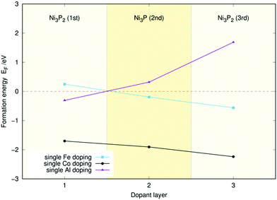 | ||
| Fig. 2 Single-atom doping energies (EF) for Fe, Co, and Al for the three topmost layers of the Ni3P2 termination of Ni2P. | ||
It seems that the doping energy in Fig. 3 is almost exclusively determined by the layer of the dopant atoms, as the energies remain almost identical when the position of the iron dopant is modified within a layer. The energy is also seen to decrease the deeper the atoms are, indicating that the dopant atoms would not aggregate on the material's surface but rather a few layers down.
An interesting feature of Fig. 3 is that the decrease in energy for both Co and Fe as one moves down in layers appears almost linear. This is reflected in Fig. 2, where the single-atom doping energy decreases fairly linearly for Co and Fe. Indeed, for most cases in Fig. 3, one can predict the doping energies to less than 0.1 eV just by adding the single-doping energies of Fig. 2 together. This implies minimal cooperation effects between the two dopants.
Similarly to Fig. 3, Fig. 4 and 5 contain the doping energies for the (Co, Al) and (Al, Fe) systems. As in the (Co, Fe) case, the energy is mostly unaffected by the dopant's position in a given layer for both metal combinations. Furthermore, Co and Fe follow the same trends as they did before: The energy of the system decreases the lower the layer of the Co or Fe dopant. Aluminium follows the opposite trend: Its doping energy is at the lowest in layer one and increases significantly for the two subsequent layers. For both figures, the energies largely follow the linear trends predicted from Fig. 2. The only exception to this in Fig. 5 is the (Al, Fe) (l3, l2) doping scheme with Fe at the 2nd position. There, the substantial energy difference arises from a restructuring of the surface. Similar anomalies caused by surface reconstructions were occasionally observed in our single dopant study.33 Regardless, the doping energies can almost always be predicted to an accuracy of 0.1 eV using the individual atom doping energies from Fig. 2, as in the (Co, Fe) case. Thus, the coordination effects appear small also for the (Co, Al) and (Al, Fe) surfaces.
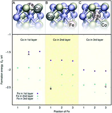 | ||
| Fig. 3 Two-atom doping energies (EF) for Co and Fe for the top three layers of the Ni3P2 termination of Ni2P. Panels A, B, and C provide sample geometries for their respective data points. | ||
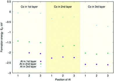 | ||
| Fig. 4 Two-atom doping energies (EF) for Co and Al for the three topmost layers of the Ni3P2 termination of Ni2P. | ||
3.2 Hydrogen adsorption free energies
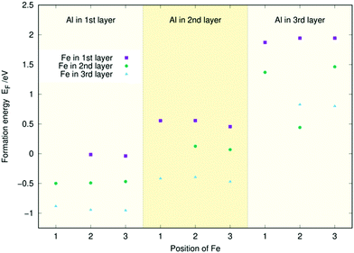 | ||
| Fig. 5 Two-atom doping energies (EF) for Al and Fe for the three topmost layers of the Ni3P2 termination of Ni2P. | ||
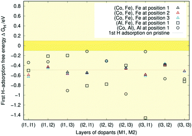
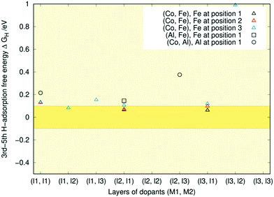
The central message from Fig. 6 is that all the data lie below the optimal range of ±0.1 eV. This indicates that with little previous H-coverage, the surface binds hydrogen too strongly for HER to occur effectively. There is considerable variation in the first adsorption free energy for the Al-containing doping schemes with some structures right at the border of the optimal range and others like (Al, Fe) (l3, l1) more than twice lower in energy than the pristine case. The first adsorption free energies are closest to optimal when aluminium is present in the first layer and the second dopant is in some other layer. If both dopants are in the first layer, the free energy is lower. These findings line up with our previous results where single Al doping of the topmost Ni3P2 layer resulted in a free energy of −0.02 eV, whereas on a triply Al-doped surface layer, the free energy decreased to −0.37 eV.32 The lower adsorption free energies are generally encountered when aluminium is not in the topmost layer. Meanwhile, the (Co, Fe) free energies show trends similar to those observed in our recent doping study,33 as all energies remain relatively close to the pristine one. Comparing the coloured symbols' locations, we see that changing the dopant position within a layer has little impact on the adsorption free energy, as expected.
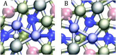
In line with previous studies,32,33,52,63 the Ni3 hollow site depicted in Fig. 1 and various bridge sites predominated the adsorption geometries: In 19 out of the studied 42 surfaces, the first hydrogen was found in the Ni3 deep site. In an equal number of cases, the hydrogen ended up on one of the edges of the Ni3 site. These bridge configurations were commonplace when the dopants were located in the top two layers, as expected based on the finding that in low doping conditions, hollow site adsorption is most perturbed by substitutional doping of the first layer.33 Indeed, Hakala and Laasonen32 observed that low Al doping of the surface layer weakened the hollow site's binding energy, resulting in H coordination by the two Ni atoms. When Al was located in the third layer, we occasionally observed a restructuring of the surface in which one of the P atoms lifted about 1 Å from the topmost Ni3P2-layer, attaching to the hydrogen. Model cases for the two prevailing adsorption patterns are shown in Fig. 7.
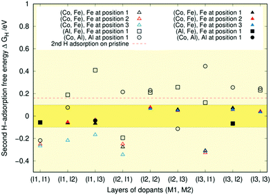
All metal combinations in Fig. 8 show structures where the second hydrogen adsorption falls within the ideal region and the free energies are naturally higher than the first adsorption free energies. When calculations with more than two hydrogens are included, approximately two-thirds of the adsorption sites are ideal for the (Co, Fe) surfaces. In contrast, for both (Al, Fe) and (Co, Al), the adsorption free energy of the second hydrogen is in many cases already too high, indicating that the hydrogen does not stick to the surface. Only the iron and cobalt doped surfaces possess plenty of adsorption geometries in the optimal region. This provides another computational verification of the experimental results that both Fe and Co doping can enhance catalytic activity.25–31,64–73 One reason behind this might be that the surface provides partially positive Ni–Co–Fe metal centres and partially negative P sites that act as hydride and proton acceptors, respectively. On the other hand, the Ni d8 electron contribution to the metallic bands is perhaps too much above the optimal chemisorption of H+.66 The shift in the d-band centre with respect to the Fermi level caused by dopant atoms with fewer d-electrons can reduce the chemical interaction between the reaction intermediates and the catalyst surface.13,18,66,74
As was the case for the first hydrogen adsorption, the free energy seems almost independent of the atom's position within the layer. The only exceptions are the three doping schemes on the left of Fig. 8, where position three is somehow always lower in energy.
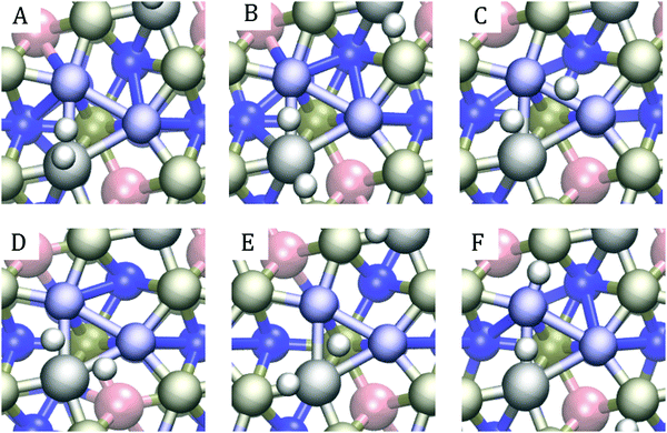
In all but one case, multiple bonding patterns exist within the ideal region. Six such patterns for (Co, Fe) (l1, l2) with the iron in the second position are illustrated in Fig. 9. Panel E shows the most common bonding pattern for (Co, Fe) where one of the hydrogens stays at the Ni3 hollow site, and the other occupies a metal–phosphorus bridge site. Only one of the (Co, Fe) doping schemes within the ideal region did not feature this geometry. This is unsurprising, given that the same bonding pattern was found for the pristine surface by Liu and Rodriguez63 and that it was also the most prevalent pattern observed in our previous study.33 Even though the negatively partially charged phosphorus primarily attracts hydronium ions, it also participates in bonding hydrogen after the hydrogen atoms have poisoned the deep Ni3-sites. This dual role of the P atoms results in an orbital environment that is more conducive for HER.
Besides the bridge – hollow site bonding pattern, we saw combinations of different bridge sites, as shown in panels B, C, D, and F of Fig. 9, and combinations of bridge site and single atom adsorptions. In a rare cases, even spontaneous hydrogen formation was observed, as in panel A. The same patterns are observed for (Co, Al) and (Al, Fe) and demonstrate the cornucopia of distinct and active catalytic sites available on these surfaces.
In most cases, the higher adsorption free energies are above the optimal region. Even when they are not, only a single adsorption geometry lies within the optimal region, as shown by the lack of full symbols in Fig. 10. Apparently, as the H-coverage increases, the surface can no longer bind hydrogen effectively. For these geometries, a dopant atom on the first layer typically binds three of the hydrogen atoms. This structure is reminiscent of the P-adatom's adsorption pattern in the Ni3P2 + P termination of Ni2P observed in previous studies.32,33,52
In summary, the Ni3P2-terminated Ni2P surface contains several very strongly binding Ni3-sites. Thus, some coverage seems necessary for the HER to proceed effectively. Once the deep sites have been poisoned by hydrogen atoms, the partially negatively charged phosphorus starts to participate in the bonding of hydrogen, creating a highly conducive orbital environment for HER. However, if the H-coverage increases too much, the surface becomes unable to bind hydrogen sufficiently strongly for effective H2 formation.
The cobalt and iron co-doped surface appears most active of the three studied. This preference might arise because dopant atoms with fewer d-electrons can decrease the chemical interaction between the reaction intermediates and the catalyst surface, which could be too strong for Ni2P alone.13,18,66,74 Iron and cobalt are chemically more similar to nickel than aluminium is. Consequently, as the pristine Ni2P surface is already relatively HER active, the presence of Al dopants might perturb the orbital environment too much and lead to the generally weaker chemical binding of the second hydrogen observed in Fig. 8.
4 Conclusions
In this study, we have investigated the hydrogen evolution reaction on Ni3P2 terminated Ni2P surfaces with two different metal atom dopants. Based on our previous computational studies,32,33 we focused on mixtures of Co, Fe, and Al. The catalytic HER activity was estimated using the hydrogen adsorption free energy, following the self-consistent scheme proposed by Nørskov et al.34,35 In most cases, the adsorption free energy of the second hydrogen fell in the optimal region of |ΔGH| < 0.1 eV. This indicates that some H-coverage is needed to poison the strongly binding Ni3 sites before the HER can proceed effectively. Of the three studied metal combinations, the Co and Fe co-doped surface emerged as the most active. The observed adsorption patterns were similar to those reported in the literature, with bridge and Ni3 hollow site occupations predominating. We speculate that the success of the Co and Fe doped surface might lie in a favourable shift in the d-band centre relative to the Fermi level, caused by dopant atoms with fewer d-electrons. In contrast, the Al-atoms might perturb the already favourable electronic environment of Ni2P slightly too much.To study the stability of our materials, we investigated the formation energies of the doped surfaces. We predict that the surface should be readily dopable by all three mixtures. Al is most likely found on the surface for the top three layers, whereas the material seems to increase in stability the deeper the Fe and Co atoms are located.
Overall, our DFT calculations predict that the co-doping of Ni2P, especially with Co and Fe, will lead to stable surfaces with improved catalytic activity. It seems that the incorporation of two different types of effective dopant atoms can result in the formation of new types of active sites. Since a real co-doped Ni2P surface would include similar types of active sites as the solely Co or Fe doped surfaces, the appearance of novel sites should further enhance the catalytic activity of the surface within the accuracy of the employed model.
Conflicts of interest
There are no conflicts to declare.Acknowledgements
We are grateful for the generous computing resources from CSC-IT Center for Scientific Computing and Mikko Hakala for useful scripts and tips throughout the project.References
- N. S. Lewis and D. G. Nocera, Powering the planet: Chemical challenges in solar energy utilization, Proc. Natl. Acad. Sci. U. S. A., 2006, 103, 15729–15735 CrossRef CAS PubMed.
- N. Armaroli and V. Balzani, Towards an electricity-powered world, Energy Environ. Sci., 2011, 4, 3193–3222 RSC.
- Z. W. Seh, J. Kibsgaard, C. F. Dickens, I. Chorkendorff, J. K. Nørskov and T. F. Jaramillo, Combining theory and experiment in electrocatalysis: Insights into materials design, Science, 2017, 355, eaad4998 CrossRef PubMed.
- F. E. Osterloh and B. A. Parkinson, Recent developments in solar water-splitting photocatalysis, MRS Bull., 2011, 36, 17–22 CrossRef CAS.
- P. Slovic, J. H. Flynn and M. Layman, Perceived risk, trust, and the politics of nuclear waste, Science, 1991, 254, 1603–1607 CrossRef CAS PubMed.
- L. Schlapbach and A. Züttel, Hydrogen-storage materials for mobile applications, Nature, 2001, 414, 353–358 CrossRef CAS PubMed.
- W. Cui, Q. Liu, N. Cheng, A. M. Asiri and X. Sun, Activated carbon nanotubes: A highly-active metal-free electrocatalyst for hydrogen evolution reaction, Chem. Commun., 2014, 50, 9340–9342 RSC.
- J. R. McKone, S. C. Marinescu, B. S. Brunschwig, J. R. Winkler and H. B. Gray, Earth-abundant hydrogen evolution electrocatalysts, Chem. Sci., 2014, 5, 865–878 RSC.
- S. Anantharaj, S. R. Ede, K. Sakthikumar, K. Karthick, S. Mishra and S. Kundu, Recent trends and perspectives in electrochemical water splitting with an emphasis on sulfide, selenide, and phosphide catalysts of Fe, Co, and Ni: A review, ACS Catal., 2016, 6, 8069–8097 CrossRef CAS.
- Y. Wang, B. Kong, D. Zhao, H. Wang and C. Selomulya, Strategies for developing transition metal phosphides as heterogeneous electrocatalysts for water splitting, Nano Today, 2017, 15, 26–55 CrossRef CAS.
- F. Davodi, M. Tavakkoli, J. Lahtinen and T. Kallio, Straightforward synthesis of nitrogen-doped carbon nanotubes as highly active bifunctional electrocatalysts for full water splitting, J. Catal., 2017, 353, 19–27 CrossRef CAS.
- A. Li, Y. Sun, T. Yao and H. Han, Earth-abundant transition-metal-based electrocatalysts for water electrolysis to produce renewable hydrogen, Chem. – Eur. J., 2018, 24, 18334–18355 CrossRef CAS PubMed.
- D. Khalafallah, M. Zhi and Z. Hong, Recent trends in synthesis and investigation of nickel phosphide compound/hybrid-based electrocatalysts towards hydrogen generation from water electrocatalysis, Top. Curr. Chem., 2019, 377, 29 CrossRef PubMed.
- C. Hu, C. Lv, S. Liu, Y. Shi, J. F. Song, Z. Zhang, J. Cai and A. Watanabe, Nickel phosphide electrocatalysts for hydrogen evolution reaction, Catalysts, 2020, 10, 188 CrossRef CAS.
- M. Ledendecker, H. Schlott, M. Antonietti, B. Meyer and M. Shalom, Experimental and theoretical assessment of Ni-based binary compounds for the hydrogen evolution reaction, Adv. Energy Mater., 2017, 7, 1601735 CrossRef.
- V. Vij, S. Sultan, A. M. Harzandi, A. Meena, J. N. Tiwari, W.-G. Lee, T. Yoon and K. S. Kim, Nickel-based electrocatalysts for energy-related applications: Oxygen reduction, oxygen evolution, and hydrogen evolution reactions, ACS Catal., 2017, 7, 7196–7225 CrossRef CAS.
- Z. Zhou, L. Wei, Y. Wang, H. E. Karahan, Z. Chen, Y. Lei, X. Chen, S. Zhai, X. Liao and Y. Chen, Hydrogen evolution reaction activity of nickel phosphide is highly sensitive to electrolyte pH, J. Mater. Chem. A, 2017, 5, 20390–20397 RSC.
- A. Ray, S. Sultana, L. Paramanik and K. M. Parida, Recent advances in phase, size, and morphology-oriented nanostructured nickel phosphide for overall water splitting, J. Mater. Chem. A, 2020, 8, 19196–19245 RSC.
- Y. Sun, L. Hang, Q. Shen, T. Zhang, H. Li, X. Zhang, X. Lyu and Y. Li, Mo doped Ni2P nanowire arrays: An efficient electrocatalyst for the hydrogen evolution reaction with enhanced activity at all pH values, Nanoscale, 2017, 9, 16674–16679 RSC.
- J. L. Lado, X. Wang, E. Paz, E. Carbó-Argibay, N. Guldris, C. Rodríguez-Abreu, L. Liu, K. Kovnir and Y. V. Kolen’ko, Design and synthesis of highly active Al–Ni–P foam electrode for hydrogen evolution reaction, ACS Catal., 2015, 5, 6503–6508 CrossRef CAS.
- Y. Zhang, Y. Liu, M. Ma, X. Ren, Z. Liu, G. Du, A. M. Asiri and X. Sun, A Mn-doped Ni2P nanosheet array: An efficient and durable hydrogen evolution reaction electrocatalyst in alkaline media, Chem. Commun., 2017, 53, 11048–11051 RSC.
- Z. Jin, P. Li, X. Huang, G. Zeng, Y. Jin, B. Zheng and D. Xiao, Three-dimensional amorphous tungsten-doped nickel phosphide microsphere as an efficient electrocatalyst for hydrogen evolution, J. Mater. Chem. A, 2014, 2, 18593–18599 RSC.
- L. Wen, J. Yu, C. Xing, D. Liu, X. Lyu, W. Cai and X. Li, Flexible vanadium-doped Ni2P nanosheet arrays grown on carbon cloth for an efficient hydrogen evolution reaction, Nanoscale, 2019, 11, 4198–4203 RSC.
- K. N. Dinh, X. Sun, Z. Dai, Y. Zheng, P. Zheng, J. Yang, J. Xu, Z. Wang and Q. Yan, O2 plasma and cation tuned nickel phosphide nanosheets for highly efficient overall water splitting, Nano Energy, 2018, 54, 82–90 CrossRef CAS.
- L. Han, T. Yu, W. Lei, W. Liu, K. Feng, Y. Ding, G. Jiang, P. Xu and Z. Chen, Nitrogen-doped carbon nanocones encapsulating with nickel–cobalt mixed phosphides for enhanced hydrogen evolution reaction, J. Mater. Chem. A, 2017, 5, 16568–16572 RSC.
- Y. Li, J. Liu, C. Chen, X. Zhang and J. Chen, Preparation of NiCoP hollow quasi-polyhedra and their electrocatalytic properties for hydrogen evolution in alkaline solution, ACS Appl. Mater. Interfaces, 2017, 9, 5982–5991 CrossRef CAS PubMed.
- J. Liu, Z. Wang, J. David, J. Llorca, J. Li, X. Yu, A. Shavel, J. Arbiol, M. Meyns and A. Cabot, Colloidal Ni2−xCoxP nanocrystals for the hydrogen evolution reaction, J. Mater. Chem. A, 2018, 6, 11453–11462 RSC.
- P. Wang, Z. Pu, Y. Li, L. Wu, Z. Tu, M. Jiang, Z. Kou, I. S. Amiinu and S. Mu, Iron-doped nickel phosphide nanosheet arrays: An efficient bifunctional electrocatalyst for water splitting, ACS Appl. Mater. Interfaces, 2017, 9, 26001–26007 CrossRef CAS PubMed.
- Y. Li, H. Zhang, M. Jiang, Q. Zhang, P. He and X. Sun, 3D self-supported Fe-doped Ni2P nanosheet arrays as bifunctional catalysts for overall water splitting, Adv. Funct. Mater., 2017, 27, 1702513 CrossRef.
- H. Huang, C. Yu, C. Zhao, X. Han, J. Yang, Z. Liu, S. Li, M. Zhang and J. Qiu, Iron-tuned super nickel phosphide microstructures with high activity for electrochemical overall water splitting, Nano Energy, 2017, 34, 472–480 CrossRef CAS.
- C. Lin, D. Wang, H. Jin, P. Wang, D. Chen, B. Liu and S. Mu, Construction of an iron and oxygen co-doped nickel phosphide based on MOF derivatives for highly efficient and long-enduring water splitting, J. Mater. Chem. A, 2020, 8, 4570–4578 RSC.
- M. Hakala and K. Laasonen, Hydrogen adsorption trends on Al-doped Ni2P surfaces for optimal catalyst design, Phys. Chem. Chem. Phys., 2018, 20, 13785–13791 RSC.
- L. Partanen, M. Hakala and K. Laasonen, Hydrogen adsorption trends on various metal-doped Ni2P surfaces for optimal catalyst design, Phys. Chem. Chem. Phys., 2019, 21, 184–191 RSC.
- J. K. Nørskov, J. Rossmeisl, A. Logadottir, L. Lindqvist, J. R. Kitchin, T. Bligaard and H. Jónsson, Origin of the overpotential for oxygen reduction at a fuel-cell cathode, J. Phys. Chem. B, 2004, 108, 17886–17892 CrossRef.
- J. K. Nørskov, T. Bligaard, A. Logadottir, J. R. Kitchin, J. G. Chen, S. Pandelov and U. Stimming, Trends in the exchange current for hydrogen evolution, J. Electrochem. Soc., 2005, 152, J23–J26 CrossRef.
- J. Greeley, T. F. Jaramillo, J. Bonde, I. Chorkendorff and J. K. Nørskov, Computational high-throughput screening of electrocatalytic materials for hydrogen evolution, Nat. Mater., 2006, 5, 909–913 CrossRef CAS PubMed.
- M. H. Hansen, L.-A. Stern, L. Feng, J. Rossmeisl and X. Hu, Widely available active sites on Ni2P for electrochemical hydrogen evolution – insights from first principles calculations, Phys. Chem. Chem. Phys., 2015, 17, 10823–10829 RSC.
- R. B. Wexler, J. M. P. Martirez and A. M. Rappe, Stable phosphorus-enriched (0001) surfaces of nickel phosphides, Chem. Mater., 2016, 28, 5365–5372 CrossRef CAS.
- Q. Li and X. Hu, First-principles study of Ni2P(0001) surfaces, Phys. Rev. B: Condens. Matter Mater. Phys., 2006, 74, 035414 CrossRef.
- Y.-H. Chung, K. Gupta, J.-H. Jang, H. S. Park, I. Jang, J. H. Jang, Y.-K. Lee, S.-C. Lee and S. J. Yoo, Rationalization of electrocatalysis of nickel phosphide nanowires for efficient hydrogen production, Nano Energy, 2016, 26, 496–503 CrossRef CAS.
- J. VandeVondele, M. Krack, F. Mohamed, M. Parrinello, T. Chassaing and J. Hutter, QUICKSTEP: Fast and accurate density functional calculations using a mixed Gaussian and plane waves approach, Comput. Phys. Commun., 2005, 167, 103–128 CrossRef CAS.
- J. Hutter, M. Iannuzzi, F. Schiffmann and J. VandeVondele, cp2k: Atomistic simulations of condensed matter systems, Wiley Interdiscip. Rev.: Comput. Mol. Sci., 2014, 4, 15–25 CAS.
- J. P. Perdew, K. Burke and M. Ernzerhof, Generalized gradient approximation made simple, Phys. Rev. Lett., 1996, 77, 3865–3868 CrossRef CAS PubMed.
- S. Goedecker, M. Teter and J. Hutter, Separable dual-space Gaussian pseudopotentials, Phys. Rev. B: Condens. Matter Mater. Phys., 1996, 54, 1703–1710 CrossRef CAS PubMed.
- C. Hartwigsen, S. Goedecker and J. Hutter, Relativistic separable dual-space Gaussian pseudopotentials from H to Rn, Phys. Rev. B: Condens. Matter Mater. Phys., 1998, 58, 3641–3662 CrossRef CAS.
- M. Krack, Pseudopotentials for H to Kr optimized for gradient-corrected exchange–correlation functionals, Theor. Chem. Acc., 2005, 114, 145–152 Search PubMed.
- P. Haas, F. Tran and P. Blaha, Calculation of the lattice constant of solids with semilocal functionals, Phys. Rev. B: Condens. Matter Mater. Phys., 2009, 79, 085104 CrossRef.
- A. H. Reshak and M. Jamal, Calculation of the lattice constant of hexagonal compounds with two dimensional search of equation of state and with semilocal functionals a new package (2D-optimize), J. Alloys Compd., 2013, 555, 362–366 CrossRef CAS.
- F. Tran, R. Laskowski, P. Blaha and K. Schwarz, Performance on molecules, surfaces, and solids of the Wu-Cohen GGA exchange–correlation energy functional, Phys. Rev. B: Condens. Matter Mater. Phys., 2007, 75, 115131 CrossRef.
- S. Grimme, J. Antony, S. Ehrlich and H. Krieg, A Consistent and accurate ab initio parametrization of density functional dispersion correction (DFT-D) for the 94 elements H-Pu, J. Chem. Phys., 2010, 132, 154104 CrossRef PubMed.
- S. Grimme, S. Ehrlich and L. Goerigk, Effect of the damping function in dispersion corrected density functional theory, J. Comput. Chem., 2011, 32, 1456–1465 CrossRef CAS PubMed.
- R. B. Wexler, J. M. P. Martirez and A. M. Rappe, Active role of phosphorus in the hydrogen evolving activity of nickel phosphide(0001) surfaces, ACS Catal., 2017, 7, 7718–7725 CrossRef CAS.
- A. B. Hernandez, H. Ariga, S. Takakusagi, K. Kinoshita, S. Suzuki, S. Otani, S. T. Oyama and K. Asakura, Dynamical LEED analysis of Ni2P(0001)-1 × 1: Evidence for P-covered surface structure, Chem. Phys. Lett., 2011, 513, 48–52 CrossRef CAS.
- D. Kanama, S. T. Oyama, S. Otani and D. F. Cox, Photoemission and LEED characterization of Ni2P(0001), Surf. Sci., 2004, 552, 8–16 CrossRef CAS.
- M. G. Moula, S. Suzuki, W.-J. Chun, S. Otani, S. T. Oyama and K. Asakura, Surface structures of Ni2P(0001)-scanning tunneling microscopy (STM) and low-energy electron diffraction (LEED) characterizations, Surf. Interface Anal., 2006, 38, 1611–1614 CrossRef CAS.
- S. Suzuki, G. M. Moula, T. Miyamoto, Y. Nakagawa, K. Kinosthita, K. Asakura, S. T. Oyama and S. Otani, Scanning tunneling microscopy and photoemission electron microscopy studies on single crystal Ni2P surfaces, J. Nanosci. Nanotechnol., 2009, 9, 195–201 CrossRef CAS PubMed.
- D. Guo, Y. Nakagawa, H. Ariga, S. Suzuki, K. Kinoshita, T. Miyamoto, S. Takakusagi, K. Asakura, S. Otani and S. T. Oyama, STM studies on the reconstruction of the Ni2P (10
![[1 with combining macron]](https://www.rsc.org/images/entities/char_0031_0304.gif) 0) surface, Surf. Sci., 2010, 604, 1347–1352 CrossRef CAS.
0) surface, Surf. Sci., 2010, 604, 1347–1352 CrossRef CAS. - H. Ariga, M. Kawashima, S. Takakusagi and K. Asakura, Density function theoretical investigation on the Ni3PP structure and the hydrogen adsorption property of the Ni2P(0001) surface, Chem. Lett., 2013, 42, 1481–1483 CrossRef CAS.
- P. Liu, J. A. Rodriguez, T. Asakura, J. Gomes and K. Nakamura, Desulfurization reactions on Ni2P(001) and α-Mo2C(001) surfaces: Complex role of P and C sites, J. Phys. Chem. B, 2005, 109, 4575–4583 CrossRef CAS PubMed.
- J. A. Rodriguez, J.-Y. Kim, J. C. Hanson, S. J. Sawhill and M. E. Bussell, Physical and chemical properties of MoP, Ni2P, and MoNiP hydrodesulfurization catalysts: Time-resolved X-ray diffraction, density functional, and hydrodesulfurization activity studies, J. Phys. Chem. B, 2003, 107, 6276–6285 CrossRef CAS.
- B. Hammer, L. B. Hansen and J. K. Nørskov, Improved adsorption energetics within density-functional theory using revised Perdew–Burke–Ernzerhof functionals, Phys. Rev. B: Condens. Matter Mater. Phys., 1999, 59, 7413–7421 CrossRef.
- E. Skúlason, G. S. Karlberg, J. Rossmeisl, T. Bligaard, J. Greeley, H. Jónsson and J. K. Nørskov, Density functional theory calculations for the hydrogen evolution reaction in an electrochemical double layer on the Pt(111) electrode, Phys. Chem. Chem. Phys., 2007, 9, 3241–3250 RSC.
- P. Liu and J. A. Rodriguez, Catalysts for hydrogen evolution from the [NiFe] hydrogenase to the Ni2P(001) surface: The importance of ensemble effect, J. Am. Chem. Soc., 2005, 127, 14871–14878 CrossRef CAS.
- Y. Lu, Y. Deng, S. Lu, Y. Liu, J. Lang, X. Cao and H. Gu, MOF-derived cobalt–nickel phosphide nanoboxes as electrocatalysts for the hydrogen evolution reaction, Nanoscale, 2019, 11, 21259–21265 RSC.
- B. Ma, Z. Yang, Y. Chen and Z. Yuan, Nickel cobalt phosphide with three-dimensional nanostructure as a highly efficient electrocatalyst for hydrogen evolution reaction in both acidic and alkaline electrolytes, Nano Res., 2019, 12, 375–380 CrossRef CAS.
- H.-W. Man, C.-S. Tsang, M. M.-J. Li, J. Mo, B. Huang, L. Y. S. Lee, Y.-C. Leung, K.-Y. Wong and S. C. E. Tsang, Transition metal-doped nickel phosphide nanoparticles as electro- and photocatalysts for hydrogen generation reactions, Appl. Catal., B, 2019, 242, 186–193 CrossRef CAS.
- Y. Pan, Y. Chen, Y. Lin, P. Cui, K. Sun, Y. Liu and C. Liu, Cobalt nickel phosphide nanoparticles decorated carbon nanotubes as advanced hybrid catalysts for hydrogen evolution, J. Mater. Chem. A, 2016, 4, 14675–14686 RSC.
- B. Zhang, J. Zhang, X. Tang, Y. H. Lui and S. Hu, An investigation of Fe incorporation on the activity and stability of homogeneous (FexNi1−x)2P solid solutions as electrocatalysts for alkaline hydrogen evolution, Electrochim. Acta, 2019, 294, 297–303 CrossRef CAS.
- W. L. Kwong, C. C. Lee and J. Messinger, Scalable two-step synthesis of nickel–iron phosphide electrodes for stable and efficient electrocatalytic hydrogen evolution, J. Phys. Chem. C, 2017, 121, 284–292 CrossRef CAS.
- Y. Du, Z. Li, Y. Liu, Y. Yang and L. Wang, Nickel–iron phosphides nanorods derived from bimetallic–organic frameworks for hydrogen evolution reaction, Appl. Surf. Sci., 2018, 457, 1081–1086 CrossRef CAS.
- Q. Zhou, Z. Chen, L. Zhong, X. Li, R. Sun, J. Feng, G.-C. Wang and X. Peng, Solvothermally controlled synthesis of organic–inorganic hybrid nanosheets as efficient pH-universal hydrogen-evolution electrocatalysts, ChemSusChem, 2018, 11, 2828–2836 CrossRef CAS PubMed.
- M. Guo, Y. Qu, F. Zeng and C. Yuan, Synthetic strategy and evaluation of hierarchical nanoporous NiO/NiCoP microspheres as efficient electrocatalysts for hydrogen evolution reaction, Electrochim. Acta, 2018, 292, 88–97 CrossRef CAS.
- H. Zheng, X. Huang, H. Gao, G. Lu, A. Li, W. Dong and G. Wang, Cobalt-tuned nickel phosphide nanoparticles for highly efficient electrocatalysis, Appl. Surf. Sci., 2019, 479, 1254–1261 CrossRef CAS.
- S. Surendran, S. Shanmugapriya, A. Sivanantham, S. Shanmugam and R. Kalai Selvan, Electrospun carbon nanofibers encapsulated with NiCoP: A multifunctional electrode for supercapattery and oxygen reduction, oxygen evolution, and hydrogen evolution reactions, Adv. Energy Mater., 2018, 8, 1800555 CrossRef.
| This journal is © the Owner Societies 2021 |

