
 Open Access Article
 This Open Access Article is licensed under a
 Creative Commons Attribution 3.0 Unported Licence
Lithium ion battery degradation: what you need to know
Jacqueline S.
Edge
 ab,
Simon
O’Kane
ab,
Ryan
Prosser
ab,
Niall D.
Kirkaldy
a,
Anisha N.
Patel
a,
Alastair
Hales
a,
Abir
Ghosh
abc,
Weilong
Ai
bd,
Jingyi
Chen
d,
Jiang
Yang
a,
Shen
Li
a,
Mei-Chin
Pang
ab,
Laura
Bravo Diaz
a,
Anna
Tomaszewska
d,
M. Waseem
Marzook
a,
Karthik N.
Radhakrishnan
a,
Huizhi
Wang
a,
Yatish
Patel
a,
Billy
Wu
bd and
Gregory J.
Offer
*ab
ab,
Simon
O’Kane
ab,
Ryan
Prosser
ab,
Niall D.
Kirkaldy
a,
Anisha N.
Patel
a,
Alastair
Hales
a,
Abir
Ghosh
abc,
Weilong
Ai
bd,
Jingyi
Chen
d,
Jiang
Yang
a,
Shen
Li
a,
Mei-Chin
Pang
ab,
Laura
Bravo Diaz
a,
Anna
Tomaszewska
d,
M. Waseem
Marzook
a,
Karthik N.
Radhakrishnan
a,
Huizhi
Wang
a,
Yatish
Patel
a,
Billy
Wu
bd and
Gregory J.
Offer
*ab
aDepartment of Mechanical Engineering, Imperial College London, London SW7 2AZ, UK. E-mail: gregory.offer@imperial.ac.uk
bThe Faraday Institution, Quad One, Becquerel Avenue, Harwell Campus, Didcot, OX11 0RA, UK
cDepartment of Chemical Engineering and Technology, Indian Institute of Technology (BHU), Varanasi, Uttar Pradesh 221005, India
dDyson School of Design Engineering, Imperial College London, London SW7 2AZ, UK
First published on 22nd March 2021
Abstract
The expansion of lithium-ion batteries from consumer electronics to larger-scale transport and energy storage applications has made understanding the many mechanisms responsible for battery degradation increasingly important. The literature in this complex topic has grown considerably; this perspective aims to distil current knowledge into a succinct form, as a reference and a guide to understanding battery degradation. Unlike other reviews, this work emphasises the coupling between the different mechanisms and the different physical and chemical approaches used to trigger, identify and monitor various mechanisms, as well as the various computational models that attempt to simulate these interactions. Degradation is separated into three levels: the actual mechanisms themselves, the observable consequences at cell level called modes and the operational effects such as capacity or power fade. Five principal and thirteen secondary mechanisms were found that are generally considered to be the cause of degradation during normal operation, which all give rise to five observable modes. A flowchart illustrates the different feedback loops that couple the various forms of degradation, whilst a table is presented to highlight the experimental conditions that are most likely to trigger specific degradation mechanisms. Together, they provide a powerful guide to designing experiments or models for investigating battery degradation.
Introduction
Understanding battery degradation is critical for cost-effective decarbonisation of both energy grids1 and transport.2 However, battery degradation is often presented as complicated and difficult to understand. This perspective aims to distil the knowledge gained by the scientific community to date into a succinct form, highlighting the minimum number of papers that need to be read in order to understand lithium ion battery (LIB) degradation. Other recent reviews in this area include Kabir et al.,3 providing a classification for degradation mechanisms and modes and briefly covering key experimental techniques; Hapuarachichi et al.,5 having a strong focus on in situ experimental techniques for assessing anode degradation; Woody et al.,6 drawing out implications for best practise in LIB use and Pender et al.,7 covering the degradation of electrode materials for the extended LIB family. This perspective provides a simple and consistent classification for the main mechanisms affecting lithium intercalation materials, draws out the link between degradation mechanisms and their triggering conditions and highlights the interconnection between various mechanisms, presenting the complexity through updated figures and tables in an accessible way.The rapid market expansion for LIBs8 is driving down cost, but making LIBs last longer is just as important. This improves the lifetime economics, enables longer warranties4 and dilutes the environmental impacts associated with raw material extraction and manufacturing.9,10 Understanding battery degradation is key to increasing operational lifetime. Being able to accurately predict battery end-of-life (EoL) enables the risks of thermal runaway to be minimised.11
With time and use, the storage capacity of LIBs diminishes and the internal resistance increases,12 due to a wide range of degradation mechanisms, some occurring simultaneously, or triggering further mechanisms. Some usage patterns and operating conditions lead to rapid degradation by one or more processes and the interplay between mechanisms is still not well understood.13 This perspective presents a state-of-the-art picture of the most prominent degradation processes, presenting the latest understanding of each mechanism, experimental techniques and conditions that can trigger and/or exacerbate the degradation caused by that mechanism and the models which have been proposed to simulate it.
From a user's perspective, there are three main external stress factors that influence degradation: temperature, state of charge (SoC) and load profile. The relative importance of each of these factors varies depending on the chemistry, form factor and historic use conditions, among others. Works such as Birkl et al.14 have highlighted how these stress factors can influence the underpinning physical degradation processes, with models such as those reviewed in Reniers et al.,13 showing how individual mechanisms can be described. In general, temperature is the most significant stress factor, where deviations from the typical 25 °C can lead to accelerated failure.15 Higher SoC operation accelerates degradation, due to the relationship between the electrode potentials and the rate of parasitic side reactions, while higher current operation increases the likelihood of failure, due to mechanical stresses developing in the battery during cycling, but also promotion of lithium plating during charge.
The magnitude of these influences is also dependent on secondary factors, such as subtle manufacturing defects. Harris et al.,16 for instance, demonstrated the variability in lifetime of 24 nominally identical pouch cells, all cycled with the same load profile. While the root cause of this variability is still debated, slight variations in manufacturing conditions are likely to have played a role, thus highlighting the need for statistically significant sample sizes. This is further amplified by sensitivity to testing conditions often not controlled nor measured, such as the application of external pressure to pouch cells or thermal gradients that build up, due to internal heat generation.
Recently,17,18 attention has been drawn to the importance of path dependence,19i.e. the order in which the various degradation mechanisms are triggered through either calendar ageing, occurring while the battery is at rest, or cycle ageing, when the battery is in use or being charged. In real world usage patterns, periods of rapid (dis)charging may be interspersed with slower (dis)charging or periods of idleness, therefore investigations of this aspect are needed for more accurate lifetime prediction.
Given the topical nature of LIBs, many publications have presented models to describe their degradation. However, in the vast majority of cases, these are done in isolation of other mechanisms, ignoring their interplay. To date, the authors are not aware of any fully comprehensive model capturing all effects and their influences on each other. Some notable works have attempted to link mechanisms together, such as Yang et al.,20 who showed how the growth of the solid–electrolyte interphase (SEI) layer leads to pore blockage and subsequently an increase in the rate of lithium plating, ultimately leading to a non-linear drop-off in cell capacity. Beyond the importance of coupling the interactions between the various degradation mechanisms, the importance of path-dependency – i.e. which mechanism was triggered first – is also often understated; with the sequence of events being an important factor in determining life, especially at higher current loads.17 These complex interactions often cannot be captured accurately with empirical or semi-empirical models, instead needing physics-based models.
In this perspective, we cover the main mechanisms occurring during normal operating conditions, within the safety limits defined by the manufacturer's specifications. The structure of the perspective has three main sections, starting with descriptions of the mechanisms, their consequences and interactions, followed by experimental techniques for characterising and triggering these mechanisms. The third section covers the state-of-the art in modelling these mechanisms, including a discussion on models which attempt to capture the interactions between them.
Clarification of nomenclature
There are six main components of a typical battery: two current collectors in contact with the two electrodes, between which redox reactions take place, allowing charge/discharge; a porous separator, preventing short circuiting between the two electrodes while allowing charged ions to migrate through; and the electrolyte, which enables facile charge transfer and is an additional source of lithium ions (Li+). Fig. 1 shows these components schematically.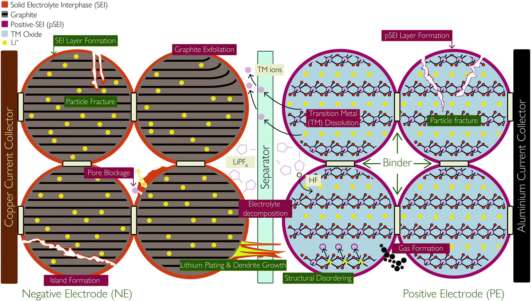 | ||
| Fig. 1 Schematic showing the basic components of a lithium ion battery cell and the location and consequences of the degradation mechanisms covered in this review, with primary mechanisms labelled in green and secondary mechanisms labelled in dark red. Reprinted (adapted) with permission from Merla et al.21 Copyright (2015), Elsevier B.V. | ||
Within some research domains, the electrodes in the LIB are referred to as the anode or cathode, defined from the electrodes’ role during the discharge process and then used absolutely. As both electrodes play the role of the anode or cathode, depending on whether the cell is charging or discharging, it is more accurate to define them by their relative electrode potentials. Hence, the electrode with the higher electrode potential, often referred to as the cathode, is herein referred to as the positive electrode (PE). It is typically a lithium transition metal (TM) oxide material, capable of undergoing reversible delithiation of Li+, and the limiting factor in determining the energy density of the battery. The other electrode – an intercalation material, usually graphite or a graphite hybrid material and sometimes lithium titanate (LTO)22 – is often referred to as the anode, but herein referred to as the negative electrode (NE).
Both the PE and NE are the active materials coated on metal foils (current collectors), which serve to facilitate electron transport to the active materials. As a cell is polarised for charging, the PE is oxidised, causing electrons to be released to the external circuit and Li+ to delithiate from the PE crystal structure. As the ions migrate across the cell and through the separator to intercalate between the layers of the NE material, electrons flow externally to the NE, reducing it and maintaining charge neutrality. Hence, both materials must undergo structural changes in order to accommodate Li+. During discharge, the reverse process takes place, where the NE is oxidised and the PE is reduced. Hence, the Li ions and electrons are shuttled back and forth in a ‘rocking chair’ fashion for charging and discharging the cell. This requires Li+ to be easily and reversibly extracted from the PE and is limited by the TM oxide crystal's ability to maintain a stable neutral crystal structure.
Mechanisms of battery degradation
Battery degradation can be described using three tiers of detail. Degradation mechanisms describe the physical and chemical changes that have occurred within the cell. Mechanisms are the most detailed viewpoint of degradation but are also typically the most difficult to observe during battery operation. The directly observable effects of degradation are capacity fade and power fade. Capacity fade is a reduction in the usable capacity of the cell and power fade is a reduction of the deliverable power of the cell after degradation. These observable effects are the least detailed viewpoint of degradation but are the easiest to measure. As a result, many practical measures of cell degradation are of capacity fade and power fade.Between degradation mechanisms and observable effects lie the degradation modes: a method of grouping degradation mechanisms, based on their overall impact on the cell's thermodynamic and kinetic behaviour. We would like to highlight four modes, all of which impact the thermodynamic behaviour of the cell, i.e. the shape of the open-circuit voltage (OCV) curve and the maximum theoretical capacity of the cell. Firstly, loss of active material (LAM), occurring in both positive and negative electrodes. This mode groups mechanisms which lead to a reduction in the material available for electrochemical activity. Secondly, loss of lithium inventory (LLI) groups mechanisms resulting in a reduction of the amount of cyclable lithium available for transport between electrodes. Thirdly, most often associated with LLI, is stoichiometric drift, where the electrodes become imbalanced relative to each other.21 Finally, impedance change groups those mechanisms affecting the kinetic behaviour of the cell. Various terms have been used in the literature to refer to this mode. Han et al.23 use the term resistance increase, while Vetter et al.24 use the term impedance rise. All of these terms lead to the same grouping of degradation mechanisms. This mode was further divided by Dubarry et al.,25 who introduced two modes termed “ohmic resistance increase” and “faradaic rate degradation”. The former arises through degradation of the electronic conduction pathways in the cell, occurring through mechanisms such as current collector corrosion. faradaic rate degradation occurs primarily through electrodes not reacting with lithium ions at the same rate as had occurred at the beginning of life and is caused by mechanisms such as SEI growth and pore blockage. A notable cause of impedance increase is related to the loss of electrolyte (LE), taking place at the interface of both electrodes due to various mechanisms, such as SEI formation, high voltages, high temperature, lithium plating, or reaction with moisture contamination resulting in hydrofluoric acid (HF) formation. These are key degradation mechanisms and are discussed in detail below. In addition, as the volume of electrolyte reduces, drying of pores and local areas within both electrodes can take place, therefore LE leads to LAM, but also leads to an increased concentration of lithium salt.
Degradation of LIBs is evidently a complex issue and this perspective aims to provide a state-of-the-art overview of the principal degradation mechanisms afflicting both electrodes, illustrated in Fig. 1. We start by discussing SEI formation and lithium plating, which are exclusively associated with the NE. Then we cover a host of interlinked mechanisms affecting the structure and decomposition of positive electrodes, including the well-known formation of the cathode electrolyte interphase (CEI), herein referred to as positive solid electrolyte interface (pSEI) for consistency. Particle fracture is discussed next, affecting both electrodes, but the special case of silicon additives in negative electrodes is also described. The final subsection discusses the developing research area of the relationship between degradation mechanisms and how they either positively or negatively reinforce each other.
Although there are other mechanisms that exist, it is not the aim of this review to extensively cover all known processes, rather to provide the reader with a distillation of knowledge of the mechanisms that are generally considered to be the most important during normal operation. Other known degradation processes include: salt precipitation, current collector corrosion, binder decomposition, separator pore blockage, electrode-current collector delamination and electrolyte evaporation, to name but a few, and are covered well in other reviews.11,23,24
SEI layer growth
The SEI layer forms initially on the first cycle of the cell, resulting in ca. 10% reduction in capacity, but then serves to stop further reaction of the electrolyte at the NE. However, the thickness of the SEI layer increases (predominantly on the graphite NE) as the cell ages. The growth could be due to various reasons, including diffusion of solvent molecules through existing SEI, new exposed electrode surfaces which result from cracking and deposition of side reaction products, such as plated Li and TM ions dissolved from the PE, which react with the electrolyte to form SEI. The SEI growth rate approximately correlates with the square root of time;29 as the SEI thickness increases, the rate of solvent molecule diffusion slows down.
(ii) Particle and SEI cracking, caused by high cycling rates, open up new surfaces for new SEI formation.
(iii) Plated Li can undergo additional side reactions with the electrolyte to form more SEI,35 illustrated in Fig. 2.
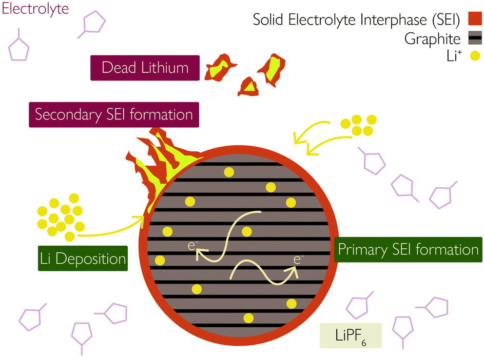 | ||
| Fig. 2 Interaction between solid–electrolyte interphase (SEI) and lithium plating. Reprinted (adapted) with permission from Zhao et al.35 Copyright (2019) Elsevier B.V. | ||
(iv) LLI from the NE causes the electrodes to become imbalanced relative to each other, stoichiometric drift21 which can lead to excessive de-lithiation and accelerated degradation of the PE at high SoCs.
Lithium plating
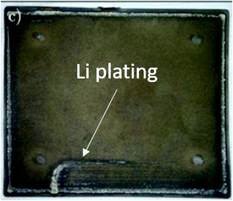 | ||
| Fig. 3 Graphite electrode after extensive Li plating. Reprinted (adapted) with permission from Campbell et al.38 Copyright (2019), The Electrochemical Society. | ||
Positive electrode structural change and decomposition
NMC materials themselves can vary significantly in their make-up, with different ratios of nickel, manganese and cobalt used in different cells. Each of these cations, with their unique properties, play a deciding role in the ageing and degradation of the PE. The main degradation mechanisms for NMC positive electrodes can be summarised as:
(i) Phase change: delithiated layered NMC structures, composed mainly of TM (Ni, Mn and Co) oxides, decompose into disordered spinel and rock salt phases, forming a passivation layer at the surface of the PE solid particles and releasing oxygen through the following process:45
| LixMO2 (layered) → LixM3O4 (spinel) → LixMO (rock salt) |
(i.e. metal/oxygen = 1![[thin space (1/6-em)]](https://www.rsc.org/images/entities/char_2009.gif) :2 → 3:4 → 1:1, [O] releases in each step) :2 → 3:4 → 1:1, [O] releases in each step) |
| In summary: LixMO2 → LixMO + [O]; [O] + [O] → O2 (g) |
(ii) Oxidation of lattice oxygen: electrochemical oxidation of oxide anions within the lattice takes place, resulting in TM dissolution or formation of rock salt phases. LiCoO2 can only be oxidised (delithiated) to Li0.5CoO2 before beginning to decompose, with loss of oxygen from the crystal lattice.47
(iii) Electrolyte decomposition and loss: nickel is not known to be stable in high oxidation states and any highly oxidised nickel species will quickly react if in contact with the electrolyte. This leads to Ni2+ dissolved in the electrolyte (which will form surface films on either electrode) and electrolyte decomposition, with consequent LE.45,48
(iv) TM/Li+ site exchange: the similar ionic radii of Li+ and Ni2+ can lead to site switching in the PE crystal lattice (also known as disordering), which can retard the diffusion of Li+ through the electrode due to reduced inter-slab space thickness, thereby increasing impedance.49
(v) Acid attack: electrolytes tend to be fluoride-containing, non-aqueous organics that are highly reactive with moisture. The presence of moisture leads to the formation of acidic species such as HF and this leads to LE.24,48 These acid species can then react with the PE material, resulting in the dissolution of TM ions from the electrode:48
| Acid attack: 2H+ + MO–R = M2+ + H2O + R |
Sources of H+:
| I: Solvent → SLo + H+ (SL+) + e− |
| II: LiPF6 = LiF + PF5; PF5 + H2O = POF3 + 2HF; 2HF = 2H+ + 2F− |
(i) pSEI formation: surface species form on either electrode due to the dissolution of TM ions during the above processes. The dissolute TM ions (Ni2+/Ni3+/Ni4+, Mn3+/Mn4+, Co3+/Co4+) react with the electrolyte to form MF2 precipitates, where M represents TMs. The MF2 species deposit onto the PE surface to form a layer of considerable thickness, in much the same way as the SEI forms on the NE, following this reaction:48,50
| 2H+ + 2F− + MO–R = MF2 (pSEI) + H2O + R |
High degrees of delithiation (LixMO2 with x < 0.3), corresponding to high cell SoCs, cause NMC structures, especially Ni-rich positive electrodes such as NMC811, to become thermodynamically unstable.53 High enough voltages can also lead to decomposition, due to oxidation of lattice oxygen.
Chemical and structural decomposition are both most likely to occur at the electrode surface. This is due to increased surface reactivity and the higher potentials experienced at the particle surface.53 To mitigate degradation, protective surface films or coatings are used in some batteries to protect the PE from attack by the electrolyte.54
High temperatures will accelerate the rate of degradation for all the mechanisms listed above.
Electrolytes tend to be non-aqueous organics and therefore highly reactive with water. Replacing these with non-organic analogues is an active area of research,55 as a route to mitigating acid dissolution of the active material.
Reactive lattice oxygen ([O]) released during electrode decomposition or phase change converts into oxygen gas (O2) or forms reactive peroxide species. The amount of O2 released is largest in the first cycle and decreases in subsequent cycles, assumed to happen because O2 releases from the surface-near regions only.45,56 The released [O] also oxidise ethylene carbonate (EC) to produce gases like CO2 and CO by the following reaction:
| (CH2O)2CO (EC) + [O] → 2CO2 (g) + CO (g) + 2H2O |
Formation of the pSEI layer and accelerated growth of the negative SEI layer due to TM dissolution will cause an increase in the cell impedance.
In one study carried out in 2017,59 cell capacity loss, impedance increase and increase of TM content in the NE are all stated to be driven, to an extent, by the rate of TM dissolution from the PE. Another study, published in 2018,34 details the specific effects at the PE and NE during Mn dissolution. On the PE side, the dissolution of Mn leads to the loss of the active material and increased impedance of the PE. However, the effect on the NE dominates.
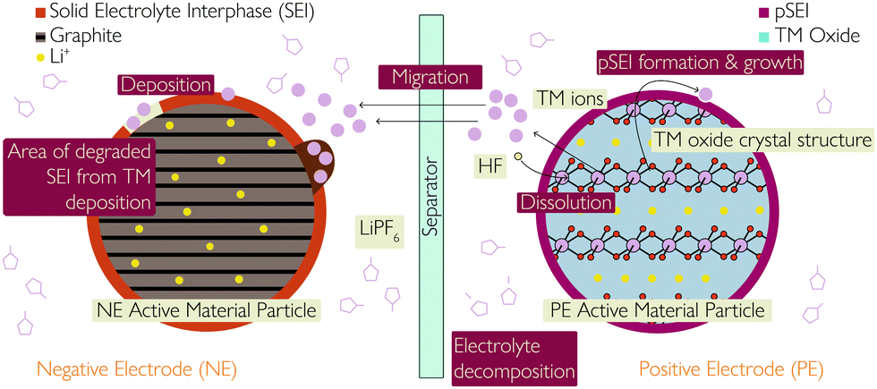 | ||
| Fig. 4 Schematic showing the various consequences and causes of transition metal dissolution, including the link with both SEI and pSEI formation and growth. | ||
Particle fracture
| Materials | Li | C | Li4Ti5O12 | Si |
|---|---|---|---|---|
| Density (g cm−3) | 0.53 | 2.25 | 3.5 | 2.33 |
| Lithiated phase | Li | LiC6 | Li7Ti5O12 | Li4.4Si |
| Theoretical specific capacity (mA h g−1) | 3862 | 372 | 175 | 4200 |
| Theoretical charge density (mA h cm−3) | 2047 | 837 | 613 | 9786 |
| Volume change (%) | 100 | 12 | 1 | 320 |
| Potential vs. Li (∼V) | 0 | 0.05 | 1.6 | 0.4 |
When lithium alloys with silicon, different Si–Li compounds form. These compounds have various unit cell volumes, with the unit cell of some of the largest compounds being almost four times larger than that of pure silicon with no alloyed lithium,67 as observed in Table 2.
| Compound and crystal structure | Unit cell volume (Å3) | Volume per silicon atom (Å3) |
|---|---|---|
| Silicon, cubic | 160.2 | 20.0 |
| Li12Si7 (Li1.71Si), orthorhombic | 243.6 | 58.0 |
| Li14Si6 (Li2.33Si), rhombohedral | 308.9 | 51.5 |
| Li13Si4 (Li3.25Si), orthorhombic | 538.4 | 67.3 |
| Li22Si5 (Li4.4Si), cubic | 659.2 | 82.4 |
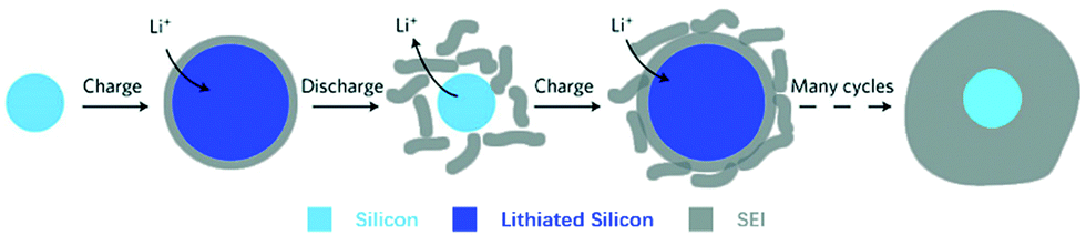
The dramatic increase in size induces stress in the electrode and can lead to mechanical failure. Particle cracking is widely observed in silicon electrodes, even with a small amount of silicon,68 and leads to very low cycle lifetimes.66 As the electrode delithiates and tends towards pure silicon, the volume contracts and electronic contact between electrode particles becomes less effective, leading to increased contact and charge transfer resistances.69 Some Li+ ions become trapped in the Si matrix, leading to irreversible capacity loss.
Alloying silicon with other metals, as well as dispersing the particles within a graphite matrix, has been shown to improve cycle life, but cycle lives are still low, compared with conventional electrodes. The cycle life of pure silicon is roughly 20 cycles, whereas the cycle life of Si–C composites is close to 70.69 Form factors that inherently constrain the electrode stack (cylindrical, prismatic) will see better performance from silicon electrodes. The charge capacity lost due to trapping of Li+ ions in the contracting Si matrix can be overcome by applying pressure during delithiation.70
(i) Disruption to electrical contact between active particles, conductive additives and current collector, therefore a loss in electronic/ionic conductivity and ultimately capacity fade,64,73 as shown in Fig. 5;
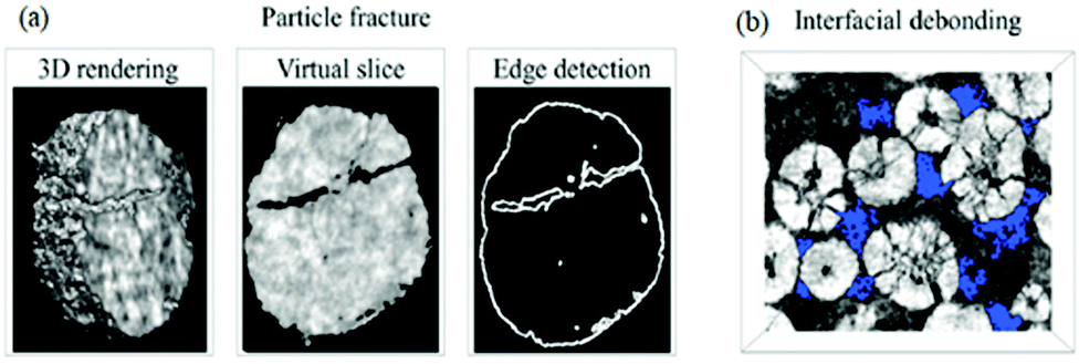 | ||
| Fig. 5 Images of the NMC cathode particles after cycling, with blue areas indicating the void regions. Reprinted with permission from Xu et al.64 Copyright (2019) Elsevier B.V. | ||
(ii) Particles beyond a certain critical size experience fracture, breaking into isolated islands;77
(iii) Increased rate of SEI and pSEI formation, discussed below, in the subsection: “Links to other mechanisms”.
All three consequences cause capacity fade. Modelling work by Laresgoiti et al.78 predicted a direct correlation between particle stress and rate of capacity loss, as shown in Fig. 6.
 | ||
| Fig. 6 Correlation of particle stress and capacity loss rate. Reprinted with permission from Laresgoiti et al.78 Copyright (2015), Elsevier B.V. | ||
(iv) Electrode pulverisation, occurring when small cracks in the electrode join up and some of the active material becomes separated from the rest of the particle. This leads to a loss in active material and hence capacity fade.
(ii) Formation of solid electrolyte films – unlike the formation of a stable SEI film in graphite, the SEI formation on alloy NEs appears to be a dynamic process of breaking off and reforming, also caused by the large volume changes of the alloy particles during cycling.66 This is illustrated in Fig. 7.
 | ||
| Fig. 7 Schematic of constantly built-up SEI layer on silicon surfaces. The initial thin SEI layer cracks during contraction of a solid silicon particle and new SEI forms on the exposed surfaces, resulting in a very thick SEI layer after many cycles. Reprinted with permission from Wu et al.80 Copyright (2012), Springer Nature. | ||
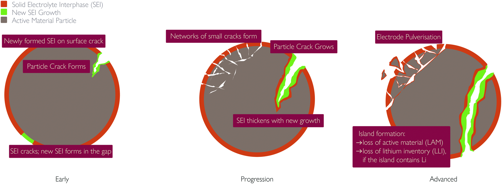 | ||
| Fig. 8 Schematic showing links between particle fracture and SEI growth. | ||
Coupling between mechanisms
Whilst extensive work has been done, with many studies describing each of these degradation mechanisms individually, the strong coupling, promotional or suppressive, between them is often neglected. Here we summarise some of the positive and negative feedback loops which have been identified. The mechanisms and their interplay are summarised in the flowchart in Fig. 9.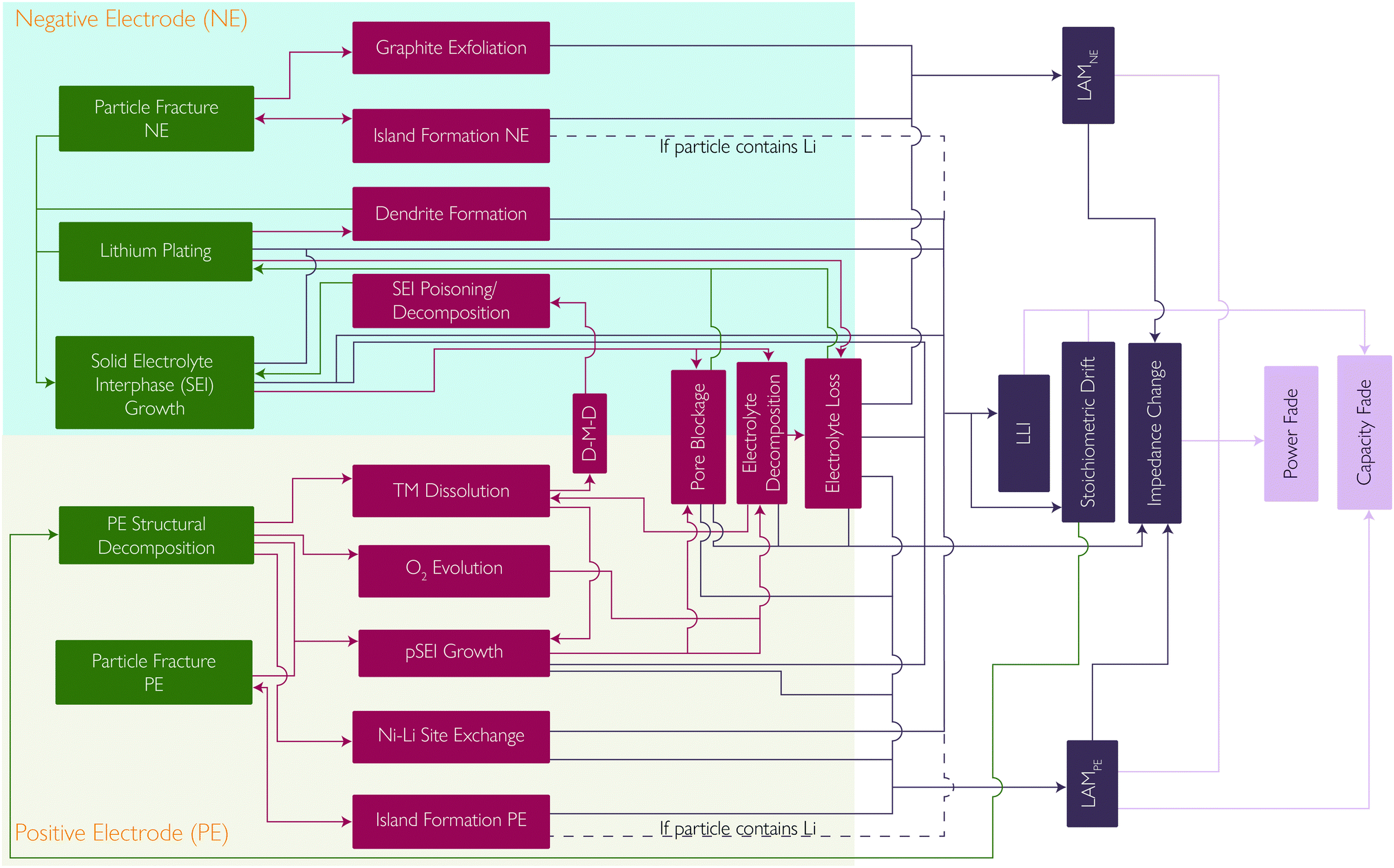 | ||
| Fig. 9 The complex interplay between the primary and secondary mechanisms explained in this review, showing how each contributes to a degradation mode and how these in turn manifest in effects on cell performance. | ||
Other degradation mechanisms are also vulnerable to positive feedback. TM dissolution and TM migration into the lithium layers of the layered oxide cathode can lead to a reduced lithium diffusivity. This can therefore lead to more severe concentration gradients and more mechanical fracture.
Mechanical fracture can also be self-reinforcing. Island formation causes the interfacial surface area of the island to become inactive, increasing the interfacial current density through the remaining active interfacial area. Increased current density results in increased concentration gradients, which in turn result in increased mechanical stress and further fracture.13
Lithium plating is highly sensitive to local electrolyte potential. SEI growth and TM deposition both cause pore blockage, decreasing the effective electrolyte conductivity and resulting in high electrolyte potentials close to the NE-separator interface, leading to lithium plating. Li plating also contributes to pore blockage, making it self-reinforcing.20
Beyond pure mechanistic interactions, it is also important to consider the sensitivity of these mechanisms to scale, with effects such as thermal gradients having detrimental impacts on lifetime.86 In this case, uneven temperature distribution, commonly found in commercial cells, can lead to heterogeneous current distributions amplifying these current and temperature sensitive degradation modes.38–41
A reduction in the lithium content from the NE will lead to the SoC of that electrode decreasing whilst the PE remains the same. This is known as stoichiometric drift and leads to a reduction in the capacity but also an increase in the PE potential at the end of charge, accelerating the PE degradation mechanisms.
Identifying and characterising degradation mechanisms
Whilst models are extremely useful for predicting future performance, their parameterisation and validation are equally essential. In much of the literature, electrochemical measurements form the foundations of characterisation, with galvanostatic methods being a key tool for establishing measurements of capacity, resistance and coulombic efficiency. Whilst relatively simple, these measurements can provide significant insight. A notable example is that of Harlow et al.87 who extensively used high precision coulometry (HPC) and incremental capacity analysis (ICA) to probe the influences of different electrolytes of a NMC532-graphite cell towards an industrial benchmark.Many variations of galvanostatic and potentiostatic methods exist, each providing different key insights. Electrochemical impedance spectroscopy (EIS), for instance, is a core technique for decoupling resistance contributions in battery electrodes. Other electrochemical techniques involving the OCV of the cell, such as analysing the curve itself,14 differential voltage analysis (DVA)68 and ICA,88 have been used to predict electrode capacities and their offset and, from this, the degradation modes of LAM and LLI. Slippage tracking is the process of monitoring the changing positions of IC or DV peaks as the battery is cycled, however this could be influenced by a range of degradation mechanisms.
Beyond electrical stimuli, a range of diffraction, spectroscopy and microscopy techniques have all been used to assess changes in electrode materials. For example, ex situ electron imaging or X-ray imaging is straightforward and hence carried out frequently, providing important parameters for models.64
The highly coupled nature of many of these degradation effects, and their multiscale and multi-physical interactions, necessitates the use of multiple techniques to gain full insights into the underpinning processes. Furthermore, there is a need to both separate out the different contributions and capture their interactions. This is particularly important to consider in ex situ coin cell experiments, where a surrogate electrolyte is used. Since electrolyte volume and additives can have a significant impact on lifetime, as well as introduce cross talk between the negative and positive electrodes, this can lead to false conclusions due to experimental artefacts. In situ measurements can be used to overcome these challenges, however these often require modifications to the cell, which themselves bring about changes in the cell behaviour.
Validation of models should always include the use of real world drive cycles, to ensure that the interconnections between models as well as path dependence are fully represented.
The focus of this part of the perspective, however, is not to exhaustively review these techniques, but instead highlight the insights they provide in the context of developing more accurate battery models.
SEI layer growth
(i) HPC to identify irreversible capacity loss (most likely due to SEI growth).
(ii) EIS to monitor the impedance changes attributable to SEI growth.
(iii) Hybrid Pulse Power Characterisation (HPPC) tests, in lieu of EIS, are also possible.
Liu et al.28 used an electrochemical quartz crystal microbalance (EQCM) to monitor how the mass of the SEI increased during formation. They confirmed these findings using in situ differential electrochemical mass spectroscopy (DEMS) and ex situ atomic force microscopy (AFM). They also found that (LiOCO2CH2)2 could be re-oxidised to form Li2O.
The mechanical properties (Young's moduli and fracture toughness) of the SEI layer would be useful properties, however, it is very challenging to measure these and, to our knowledge, no experimental study has been reported to have attempted this.
Lithium plating
(i) Resistance–capacity plot – assuming that Li plating does not increase the cell's resistance, capacity loss due to plating is equal to the difference in capacity between the cell with plating and the cell without, for the same value of resistance.
(ii) Arrhenius plots – non-Arrhenius behaviour results from Li plating, while Arrhenius behaviour results from SEI growth. Capacity loss due to Li plating is found by extrapolating the Arrhenius behaviour from higher temperatures and subtracting extrapolated and measured capacity losses at the lower temperatures.
(iii) Conditions which trigger plating result in anomalously high capacity fade rates per cycle. Zhang et al.89 assume that any capacity fade >0.024% per cycle is due to plating, but the exact value will vary between different cell types.
One proposed in situ method of quantifying plating resulting from a single charge is to detect the inverse stripping reaction through a tell-tale minimum in differential voltage (dV/dQ) plots,37 but the large spread of values in the literature call the reliability of this method into question.38,90 ICA (dQ/dV) has also been shown to have an additional minimum at high voltages when stripping occurs.91
Any of these methods can be used to parameterise a Li plating model, by adjusting the rate constant for the side reaction so that the model predicts the correct amount of Li to be plated.
Positive electrode structural change and decomposition
Oxidation of lattice oxygen is an electrochemical process, happening when the electrode potential is greater than the edge of the O2− p band.44 Due to the oxidation potentials of the TM redox couples generally being below this value, oxidation of lattice oxygen will only happen in the extremely high SoC range.
Phase change from layered to spinel or rock salt structures is more favourable at low degrees of lithiation (high SoC), corresponding to high cell voltages. Higher ambient temperature favours the phase transformation from the layered NMC structure to the rock salt layer. The bulk materials undergo a two-phase transition from their layered structure to a spinel structure and eventually to a rock salt structure at around ∼170 °C.92–94 Formation of more spinel/rock salt layer leads to [O] evolution, LAM and impedance rise.
Chemical oxidation of the electrolyte is primarily due to the presence of highly oxidised TM species (Ni4+), which also corresponds to high SoCs (and therefore high voltages).51 Due to this reaction taking place at the electrode–electrolyte interface, any conditions which lead to exposure of new electrode surfaces (e.g. particle cracking) will exacerbate this mechanism. Acid attack is due to the presence of contaminants in the electrolyte and can thus occur across the SoC range of the cell (full voltage range). Experimental studies45,46,57,58 have found that high temperature and high voltage conditions should encourage TM dissolution and eventually encourage pSEI formation. This is likely due to the high voltage at higher SoCs (60–100%) exposing fresh electrode surfaces to the electrolyte. The result is spinel/rock salt phase transformation and O2 evolution, with subsequent TM dissolution.59
The effects of these degradation mechanisms should be observable upon cell disassembly using structural and chemical analyses of the electrodes and electrolyte.56 The electrode structure can be examined using techniques such as X-ray diffraction and spectroscopy (XRD and XAS), and electron microscopy and spectroscopy (TEM, SEM, EDX and EELS), giving information about the structural change of the electrode, any defects (e.g. Ni2+/Li+ site exchange) and surface films.53 The chemical composition of the electrode could also be analysed using X-ray photoelectron spectroscopy (XPS), atomic emission spectroscopy (such as ICP-OES), or gas chromatography (GC).50,95 This would also reveal if TMs have deposited onto the NE and the composition of surface films.96
The presence of a spinel/rock salt phase at the PE particle surface and the O2 evolution from the PE have been confirmed with the help of the following experiments:
(i) Reconstructed disordered layer upon phase transformation was visualised using the atomic resolution ADF-STEM imaging, as shown in Fig. 10.
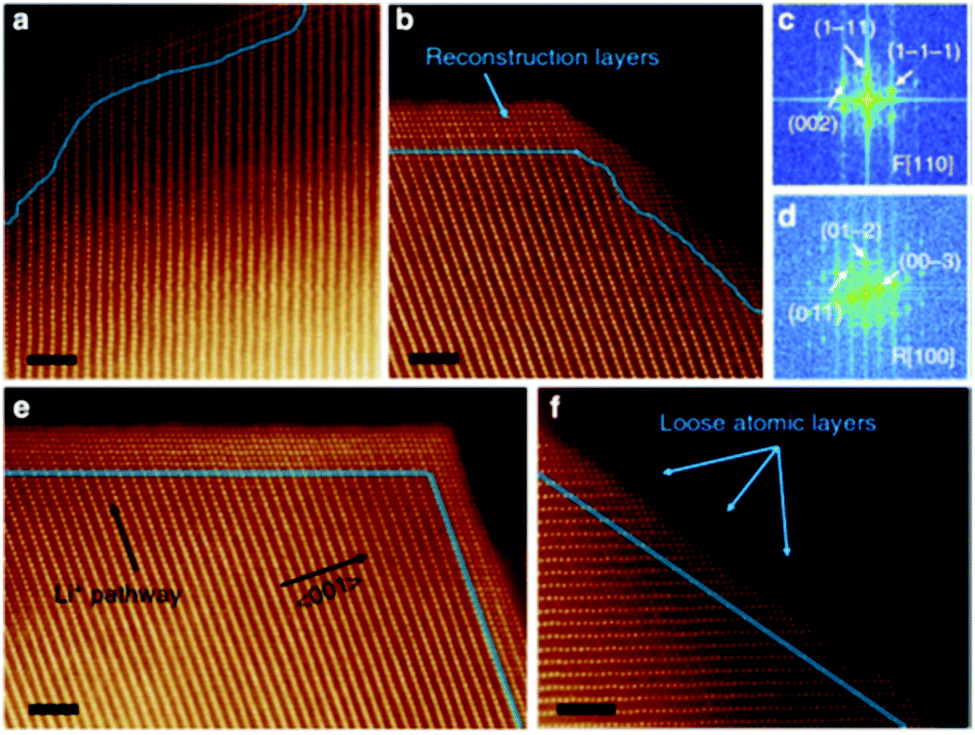 | ||
| Fig. 10 Atomic resolution ADF-STEM image of the spinel/rock salt phase. Reprinted with permission from Lin et al.56 Copyright (2012), Springer Nature. | ||
(ii) Online Electrochemical Mass Spectrometry (OEMS) has shown that at higher degrees of delithiation, all three NMC formulations (NMC111, NMC622 and NMC811) release O2 at room temperature (25 °C) which eventually reacts with EC to produce CO and CO2, as shown in Fig. 11.45
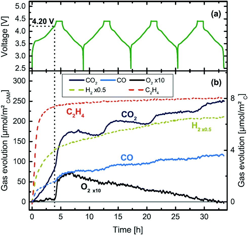 | ||
| Fig. 11 Cell voltage and gas evolution vs. time of a NMC811-graphite cell at 25 °C and 0.2 °C, over four charging/discharging cycles.45 | ||
(iii) Phase changes in the NMC materials can be tracked by plotting ICA peaks at higher voltages (3.0–4.8 V)45 and standard electrochemical characterisations at similar conditions can capture the capacity fade and impedance rise in the cell happening because of this particular degradation mechanism.
The thicknesses of both the spinel/rock salt phase and pSEI at different operating conditions reported in several publications are as follows:
(a) 15–100 nm spinel/rock salt layer thickness has been reported for different battery chemistries at different cycling, operating and storage conditions.53,97,98
(b) Comparing gas chromatographs of fresh and calendar aged electrodes, stored for a year under ambient conditions, a surface layer (pSEI) of up to ∼10 nm thickness was found on the NMC811 positive electrodes.50
Additionally, the electrolyte can be analysed for the presence of TM ions and any electrolyte degradation products using NMR, ICP-OES, UV/vis-spectroscopy and cyclic voltammetry.95
Particle fracture
Zhang66 briefly mentions the effects of temperature on cycle life in silicon/matrix negative electrodes. The findings are that higher temperatures increased the capacity of the cells per cycle, but were detrimental to the cycle life of the cell. This could be attributed to the reduction in overpotential for cells at a higher temperature, allowing more of the lithium to be removed from the silicon in normal operating voltage windows, causing smaller particle size and hence increased tensile stresses in the electrode.
There seems to be no concrete evidence of the effects of C-rate on cycle life in electrodes with silicon additives.
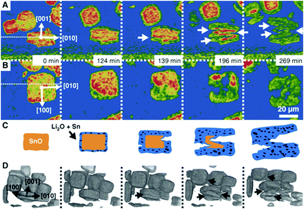 | ||
| Fig. 12 Particle fracture observed by in situ synchrotron X-ray in a model SnO system during lithiation. Reprinted with permission from Ebner et al.63 Copyright (2013), American Association for the Advancement of Science. | ||
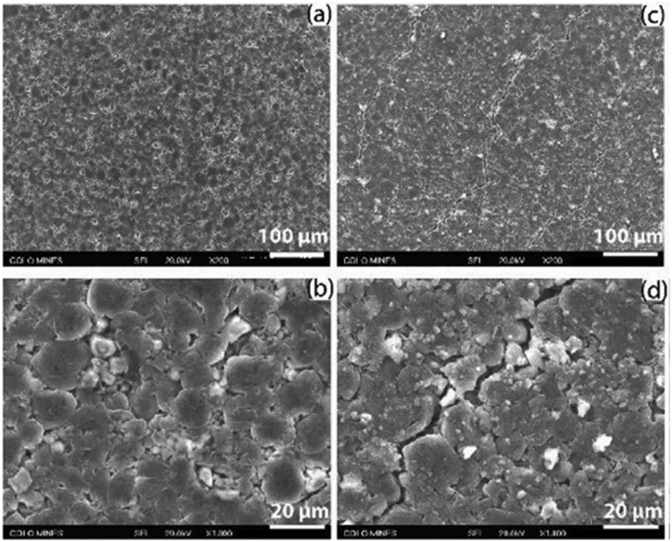 | ||
| Fig. 13 Fracture observed with SEM from the negative electrodes from an LGMJ1 18650 cell after degradation, (a and b) fresh and (c and d) aged. Reprinted with permission from Li et al.68 Copyright (2019), Elsevier B.V. | ||
Stress/strain measurements on stack level101 are highly relevant to failure analysis due to particle fracture, though they do not provide direct evidence of fracture. The stress/strain values are important parameters for fatigue models.
DVA (dV/dQ) is used to determine the LAM in the electrodes, which can be an indicator of particle fracture, the work of Li et al. being an example.68 However, other mechanisms can lead to LAM too and some fractures may not be severe enough to cause LAM.
For particle fracture, the important parameters are (1) stress/strain and (2) intrinsic mechanical properties of the materials. In situ stress/strain measurement can be done by digital image correlations, curvature measurement methods and optical fibre sensor.102 Material properties including Young's modulus, hardness and fracture strength can be measured by indentation tests.103
As a guide to designing experiments for investigating specific battery degradation mechanisms in isolation, where possible, or in concert, where required, Table 3 shows the experimental conditions which can be expected to trigger the primary and secondary degradation mechanisms covered in this perspective.
| Degradation mechanism | Subsets | T dependence | V or SoC dependence | I dependence |
|---|---|---|---|---|
| Lithium plating | Reversible, irreversible, dendritic | Low T | High V | High I |
| SEI growth | Kinetic limited, diffusion limited | High T | High V | N/A |
| Particle fracture | Graphite | Low T | More than one SoC region | High I |
| SiGr | Low T | More than one SoC region99 | High I | |
| NMC | Low T | High SoC104 | High I | |
| PE structural change and decomposition | Phase change (layered to spinel to rock salt) | High T | Both high V and SoC | High I |
| Electrochemical decomposition (oxidation of lattice oxygen) | High T | High V | High I | |
| Ni–Li site exchange (LiNiO2) | High T | High V | N/A | |
| Acid attack | High T | N/A | N/A | |
| Reaction with electrolyte | High T | High V | N/A |
Models of battery degradation
The performance and behaviour of a battery depends on the integrity of its complex inner structure. At present, it is difficult to directly measure State of Health (SoH) of a battery, as sensors placed within the structure are expensive and could disrupt the function. Instead, battery models which accurately predict their long-term behaviour can act as a “digital twin” of the battery, running alongside it as it operates and ages and occasionally resynchronising, using input from the few measurements which can be obtained, such as cell voltage, temperature and current. The SoC of a battery, essential information for smart charging, is also difficult to measure and must be estimated by the digital twin. For both SoC and SoH monitoring, simulations need to be both accurate and very fast, providing results in real time.By predicting the key performance parameters of a battery, such as capacity and lifetime, models can also be useful tools for designing electrodes, cells and packs, enabling the vast design space of batteries to be explored, where the constituent materials, electrode structure, thermal management and many more aspects can be varied and combined, without the need for expensive and potentially hazardous prototypes to be built.
Types of models
In general, there are essentially two approaches for modelling: empirical and physics-based. The former involves an incremental process of applying equations and parameters to achieve the best fit to experimental data, while the latter derives the simulated behaviour from equations known to represent the actual physical behaviour involved. In empirical models, the underlying equations may not have any real meaning, but rather attempt to emulate the behaviour of the battery, which is treated as a black box. There are also hybrid models employing simplifying techniques to achieve the speed of empirical models while harnessing the accuracy of a physics-based approach. Examples include the single particle model105 and mechanistic models,25 which use an inverse approach to estimate cell voltage and capacity for a given degradation mechanism and are becoming more widely used for machine learning (ML) and BMS.36Fig. 14 shows the various scales involved in physical and empirical models.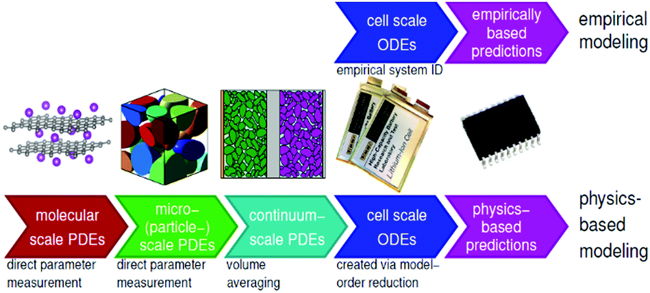 | ||
| Fig. 14 Illustration of multiscale battery modelling, represented by physics-based and empirical models. Reproduced from ECE4710/5710: Modelling, Simulation, and Identification of Battery Dynamics, courtesy of G. J. Plett.106 | ||
At the atomistic scale, no universal framework exists for simulating degradation mechanisms, but classical molecular dynamics (MD), mesoscopic modelling and ab initio density functional theory (DFT) have been used to investigate the origin and effects of cracking and stresses in Si anodes during charge112 and techniques for understanding cathode degradation have been recently reviewed.113
Doyle, Fuller and Newman have developed the widely used electrochemical model including mass conservation, charge conservation and reaction kinetics.114,115 As the model consists of a spatial variation along the thickness of the electrode and a pseudo radial dimension along the solid phase electrode particles, these models are commonly known as pseudo-two-dimensional (P2D) models. While this model can provide a comprehensive analysis of the internal dynamics of a battery,114,115 discretising and solving a physics-based model in both dimensions often result in hundreds or even thousands of equations. Therefore, implementing a physics-based model for real-time BMS monitoring is computationally expensive.
SEI layer growth
Many P2D models of SEI growth exist, all of which are predominantly based on the pioneering work of Safari et al.,29 who model solvent diffusion through the SEI layer, followed by electrochemical reactions governed by the Tafel equation, including both kinetic and diffusion limitations. Although the degradation mechanism of SEI is well captured by these physics-based models, their high computation cost is prohibitive for simulating degradation over hundreds or thousands of cycles. For this, semi-empirical and empirical models are preferred, where the fitted ageing laws capture resistance increase and capacity loss caused by SEI degradation. These ageing laws can be implemented on both physics-based and ECMs.In a semi-empirical degradation model by Zhang et al.,122 SEI layer growth is expected to be the main cause of battery degradation at temperatures between 25 and 30 °C. Key parameters such as OCV, resistance, diffusion coefficient and electrochemical reaction rates, were extracted from cycling degradation tests. With these fundamental parameters expressed as a function of cycle number, cyclical ageing could be simulated by the P2D model, while the ageing simulation based on the original physics-based degradation model of Safari et al.29 is unrealistic.
The empirical model is frequently combined with ECMs, due to their simplicity and ability to lump all the degradation physics into limited variables. In a study by Liaw et al.,123 based on lumped ECM, empirical ageing laws of resistance and capacity loss, as a result of SEI degradation, are described. Cordoba-Arenas et al.124 takes into account factors of SoC swing, current and temperature. The simplicity and proven accuracy of these models makes them suitable for battery SoH estimation. Moreover, due to the fact that the SoH Kalman filter algorithm is mostly based on equivalent circuits, SoH prediction can easily be combined with the empirical type degradation model.125 The work of Fleckenstein et al.126 introduces an SEI degradation distributed model by implementing empirical ageing laws into an electrothermal model of a large format cell. The SEI degradation inhomogeneity is represented by the distribution of impedance and capacity loss.
Above all, the physics-based model of SEI layer growth can capture the degradation behaviours with clear physical meanings. Based on the P2D model framework, the SEI degradation mode can be linked with other degradation mechanisms and there have been attempts to model the stress and fatigue behaviour with both the SEI and the electrode materials combined, where SEI properties were assumed.78
Lithium plating
Li plating and the inverse process, Li stripping, can be incorporated into P2D models by adding an additional Butler–Volmer equation for the side reaction, as first proposed by Arora, Doyle and White in 1999.127The most mathematically rigorous model in the literature is that of Yang et al.,37 illustrated in Fig. 15, as they explicitly consider dependence on both electrolyte and plated Li concentrations.
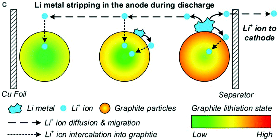 | ||
| Fig. 15 During stripping, Li metal is dissolved back into the electrolyte and then intercalated into both positive and negative electrodes. Reprinted with permission from Yang et al.37 Copyright (2018), Elsevier B.V. | ||
O’Kane et al.90 build on Yang's model by incorporating a nonlinear diffusion model that accounts for phase transitions in the graphite NE. They show that nonlinear diffusion yields qualitatively different results.
Positive electrode structural change and decomposition
PE degradation is an ongoing area of research, with several publications available on the different mechanisms of positive electrodes. However, very few studies deal with the mechanisms individually.(i) Phase change and oxygen evolution: oxygen evolution from the PE has been conventionally modelled as the oxidation of electrolyte at the PE side using a simple kinetically limited Tafel equation.13,85,128 However, this approach does not include any physics to describe the source of the oxygen evolution. Ghosh et al.129 have recently proposed the first model to include this, describing oxygen evolution from the bulk and diffusion through the rock salt layer using a shrinking core model. This model can reproduce the modes LLI and LAM, and the effects of capacity fade and power fade caused by this mechanism. Jana et al.128 proposed that the capacity fade is a linear function of the oxidation current density, which they used in the Tafel equation to model the electrolyte oxidation at the PE. This oxidation reaction also produces H2 which in turn enhances the TM dissolution.
(ii) TM dissolution and pSEI formation: TM dissolution at the PE is modelled using a first order chemical reaction, limited by concentration of H+ ions in the electrolyte.130 H+ ions are generated from LiPF6 salt dissociation in the electrolyte and solvent oxidation at the PE.130 While LiPF6 dissociation in the presence of H2O is modelled using a chemical reaction rate, solvent oxidation is modelled using irreversible Butler–Volmer kinetics.130 Lin et al.85 provided detailed P2D model equations for Mn dissolution at the PE coupled with SEI layer formation at NE. The Mn deposition on the NE is also included in the model. The growth of the pSEI can be modelled as similar to any of the SEI layer growth models.
Particle fracture
The stress model in electrode particles has been developed as a function of current, particle size and partial molar volume.74The fatigue crack model (Paris’ law) has been incorporated into a single particle model for predicting battery capacity loss.121 Crack propagation is coupled with the SEI formation and growth (diffusion dominant), to account for the loss of lithium inventory.
Morphological effects from electrode microstructures have been studied by Xu et al.,64 using finite element method in 3D. Cracks were handled by breaking the connection between two elements using a cohesive model.
 | ||
| Fig. 16 The analytical model developed to study the influence of volume expansion factor and porosity in a silicon–graphite composite electrode.131 | ||
Combined models
Fig. 17 shows the three main stages of battery degradation. The initial acceleration stage is thought to be caused by the initial SEI formation,13,85 which rapidly reduces the capacity but also hinders further SEI growth. The causes of the stabilisation (linear ageing) and saturation (nonlinear ageing) stages are more debatable. Various models of two or more degradation mechanisms have been published, each proposing a different explanation as to what causes the switch from stabilisation to saturation stages.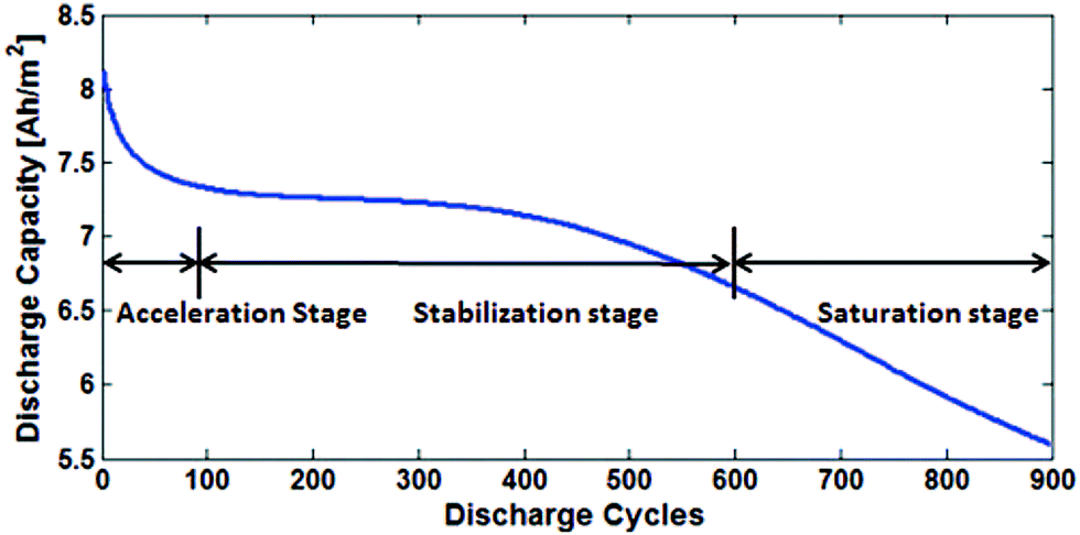 | ||
| Fig. 17 The degradation is divided into three stages: acceleration, stabilisation and saturation. Reprinted with permission from Lin et al.85 Copyright (2013), IOP Publishing. | ||
The models of Arora, Doyle and White,127 Yang et al.20 and Zhao et al.35 are notable for considering the coupling between Li plating and SEI growth, in different ways. Arora, Doyle and White127 assume that a fraction of the plated Li immediately reacts to form SEI instead of forming Li metal, but the simplicity of their model means this SEI can be stripped, as if it was plated Li. Yang et al.20 use two separate Tafel equations for the two reactions, in order to model a scenario where SEI-induced pore clogging causes rapid Li plating even at room temperature, causing the transition between the stabilisation and saturation stages of degradation. Zhao et al.35 present an updated version of Arora, Doyle and White's model that allows them to model both reversible and irreversible plating at the same time.
Few attempts have been made to model more than two degradation mechanisms at a time. Lin et al.85 presented a combined model of Mn dissolution, SEI formation and Mn deposition on the NE and analysed the combined effect of these degradation mechanisms. The model was able to qualitatively reproduce all three stages of degradation, but neither quantitative comparison with experiment nor temperature variation were included. A recent follow-up paper by Li, Landers and Park133 added a semi-empirical model of SEI formation on cracks in particles and found that the majority of SEI was formed on cracks, as opposed to growing on top of existing SEI.
Jin et al.134 combined Safari et al.'s29 model of SEI growth on the NE, the same model applied to pSEI growth on the PE and an empirical model for loss of electrical contact due to particle cracking in both electrodes. The experiments did not last long enough to include the saturation stage, but the physics-based degradation model was found to be far superior to both equivalent circuit and purely empirical models in predicting capacity loss during an EV drive cycle.
Reniers, Mulder and Howey13 devised a SPM incorporating a NE SEI model valid in both the reaction-limited and diffusion-limited extremes, a Tafel equation for irreversible lithium plating on the NE, an empirical expression for loss of electrical contact in the NE and a Tafel equation for acid dissolution of the PE. Their model results in a good qualitative fit to experimental data at 25 °C and 45 °C, but not at 5 °C, which implies their model of lithium plating could be improved.
Keil and Jossen135 presented a P2D model combining SEI growth, SEI formation on cracks and partially reversible Li plating. Like Yang et al.,20 they found that Li plating could explain the transition from linear to nonlinear ageing, even at room temperature.
From these combined models, three different possible explanations for the transition between stabilisation and saturation stages emerge. Lin et al.'s 201385 model predicts that the stabilisation stage is dominated by SEI growth on the NE while the saturation stage is dominated by acid dissolution of the PE. Yang et al.20 propose that the transition is caused by SEI-induced pore clogging, which in turn causes Li plating, neglecting the role of the PE completely. Keil and Jossen135 also found that partially reversible Li plating could explain the transition. Reniers, Mulder and Howey13 argue that their empirical model of electrical contact loss also reproduces the saturation stage.
Prospective applications of machine learning
In recent years, ML techniques have become increasingly deployed at multiple length scales to aid researchers handle the increasing volumes of data and develop new underpinning insights. At the microstructural level, Wei et al.136 demonstrated a supervised and unsupervised data mining approach to analyse larger XCT datasets for studying the effect of heterogeneous electrode particle degradation on cell level performance. Jiang et al.137 also used ML approaches to aid their tomographic analysis of interfacial degradation effects between electrode particles and binders/conductive additives which are generally difficult to segment. Here, a convolutional neural network approach was used to aid with image segmentation. However, the real power of ML approaches come from not just automating analysis, but from developing deeper insights. Gayon-Lombardo et al.,138 for instance, developed a deep convolutional generative adversarial network for the creation of synthetic microstructures. The power of these approaches further manifest themselves as these insights are integrated within a multiscale framework from atomistic length scales towards cell level control with the fusion of models, data and ML.139,140At the cell level, various authors have demonstrated the ability to provide accurate estimations of the remaining useful lifetime (RUL) by using techniques such as linear regression141 and different types of neural networks from input voltage and resistance data. Often these signals are transformed into differentials, with Severson et al.142 showing that differential capacity is a strong indicator of RUL. Extensions of these approaches which use spectroscopic information, such as EIS, have also demonstrated accurate RUL estimation from non-intuitive data sources. Zhang et al.143 for instance combined EIS measurements of batteries aged in various modes with Gaussian process regression and an automatic feature identification approach to identify two specific frequencies (2 Hz and 17 Hz) which were particularly sensitive to degradation. Here the authors attribute this to changing interfacial properties, however further validation of this was needed.
Beyond these applications, text mining tools have also been developed, such as the work by Torayev et al.144 which automatically scanned over 1800 articles and extracted key performance data for a LiO2 system. Predicting battery catastrophic failure is also an emerging domain of interest for data-driven approaches as highlighted by Finegan et al.145 However, whilst the frameworks are currently available, ensuring large enough volumes of high quality data and the fusion of multi-modal data types remains a challenge.
Conclusions
Understanding battery degradation is vital for developing high performance batteries that will meet the requirements for multiple applications. This perspective has identified five principal degradation mechanisms that are most commonly considered to be the cause of battery degradation during normal operation. These are SEI layer growth, lithium plating, PE decomposition and particle fracture at both electrodes. These five principal degradation mechanisms interact with each other and give rise to thirteen secondary degradation mechanisms, which are shown in Fig. 9, along with their interconnections. All of these degradation mechanisms result in 5 modes which are observable at the cell level. These are: LLI inventory, impedance change, stoichiometric drift, and LAM at both electrodes. These then result in operational effects such as capacity or power fade. Calendar or cycle ageing merely represent different pathways through the degradation space represented by these mechanisms.Multiple interactions between degradation mechanisms have been identified and discussed, which in many cases require further study to properly understand. Multiple explanations to explain the transition between linear and non-linear degradation were found, also known as the knee point, cell drop-off, sudden failure, etc. Two examples of coupling found to explain this include SEI layer growth leading to pore blockage and subsequent lithium plating, and SEI layer growth leading to electrolyte loss and the cell drying out. However, we found no evidence for a universal explanation that applies in every case. We consider it to be far more likely that all reported explanations are possible, as well as many not proposed yet, and that the exact combination of degradation mechanisms that leads to end-of-life will be a function of cell chemistry and how a cell is used, simply resulting again in different pathways through the degradation space. Multiple other degradation mechanisms were considered, but were not included in this perspective, as they were not generally considered to be significant during normal operation.
Battery models need to be parameterised before they can be reliably applied to particular chemistries, applications or stages of the battery life. A variety of experimental and atomistic techniques exist for battery parameterisation, but these are not well understood and there is a need for a similar, concerted effort to be made to review parameterisation techniques for battery models.
We found that degradation at the PE is generally overlooked and the majority of previous work has been focused on the negative electrode. However, with the increased use of high nickel NMC electrodes, the thermodynamic stability of the electrode is lowered and positive electrode degradation is increasingly reported as significant.
The conditions that promote or attenuate the progression of each degradation mechanism are summarised, in a way that will help inform how to operate a cell to extend life, and also inform the design of accelerated degradation experiments. Understanding that only degradation modes and not the mechanisms themselves are observable at the cell level in situ, and which degradation mechanisms result in similar modes, will also help with the design of accelerated degradation experiments for which the effects of each degradation mechanism on its own are observable. The attempts to model each degradation mechanism and a limited number of examples of attempts to couple degradation mechanisms are also summarised, in a way that will help inform future modelling attempts.
We propose that the first universal cell degradation model that would be suitable for the majority of operating conditions would need to include the 5 principal and 13 secondary degradation mechanisms that we have identified and how they interact with each other. However, consensus has not yet been reached for the governing equations for many of these mechanisms and parameterisation will be difficult, requiring modellers and experimentalists to work closely together. However, achieving this ‘moonshot’ goal would significantly advance the field of lithium ion battery modelling and would provide industry with an extremely useful tool to extend battery lifetime and performance in multiple applications.
Author contributions
Jacqueline S. Edge: conceptualisation, funding & acquisition, methodology, project administration, visualisation, writing – original draft, writing – review and editing. Simon O’Kane: conceptualisation, investigation, writing – original draft. Ryan Prosser: conceptualisation, investigation, visualisation, writing – original draft. Niall D. Kirkaldy: investigation, methodology, visualisation, writing – original draft. Anisha N. Patel: conceptualisation, writing – review and editing. Alastair Hales: investigation, methodology, writing – original draft. Abir Ghosh, Weilong Ai, Jingyi Chen, Jiang Yang, Shen Li, Laura Bravo Diaz, Karthik N. Radhakrishnan: investigation, writing – original draft. Mei-Chin Pang: project administration, writing – original draft, Anna Tomaszewska, M. Waseem Marzook: writing – original draft. Huizhi Wang, Yatish Patel: supervision, writing – review and editing. Billy Wu, Gregory J. Offer: conceptualisation, funding & acquisition, supervision, writing – original draft, writing – review and editing.Conflicts of interest
There are no conflicts to declare.Acknowledgements
This work was partially carried out with funding from the Faraday Institution (http://faraday.ac.uk; EP/S003053/1), grant number FIRG003. We would also like to thank Mr Amir Kosha Amiri for his graphical design expertise in constructing Fig. 1, 2, 4, 8 and 9.Notes and references
- D. Sanders, A. Hart, M. Ravishankar, J. Brunert, G. Strbac, M. Aunedi and D. Pudjianto, An analysis of electricity system flexibility for Great Britain, London, 2016 Search PubMed.
- G. E. Blomgren, The Development and Future of Lithium Ion Batteries, J. Electrochem. Soc., 2017, 164, A5019–A5025 CrossRef CAS.
- M. M. Kabir and D. E. Demirocak, Application of graphene and graphene-based materials in clean energy-related devices Minghui, Int. J. Energy Res., 2017, 41, 1963–1986 CrossRef CAS.
- J. C. Burns, A. Kassam, N. N. Sinha, L. E. Downie, L. Solnickova, B. M. Way and J. R. Dahn, Predicting and Extending the Lifetime of Li-Ion Batteries, J. Electrochem. Soc., 2013, 160, A1451–A1456 CrossRef CAS.
- S. N. S. Hapuarachchi, Z. Sun and C. Yan, Advances in In Situ Techniques for Characterization of Failure Mechanisms of Li-Ion Battery Anodes, Adv. Sustainable Syst., 2018, 2, 1–29 Search PubMed.
- M. Woody, M. Arbabzadeh, G. M. Lewis, G. A. Keoleian and A. Stefanopoulou, Strategies to limit degradation and maximize Li-ion battery service lifetime - Critical review and guidance for stakeholders, J. Energy Storage, 2020, 28, 101231 CrossRef.
- J. P. Pender, G. Jha, D. H. Youn, J. M. Ziegler, I. Andoni, E. J. Choi, A. Heller, B. S. Dunn, P. S. Weiss, R. M. Penner and C. B. Mullins, Electrode Degradation in Lithium-Ion Batteries, ACS Nano, 2020, 14, 1243–1295 CrossRef CAS PubMed.
- M. Wörsdörfer, T. Gül, P. Cazzola, M. Gorner, T. Bunsen, L. D’Amore, S. Scheffer, R. Schuitmaker, H. Signollet, J. Tattini and J. Teter, Global EV Outlook 2019 to electric mobility, 2019 Search PubMed.
- C. P. Grey and J. M. Tarascon, Sustainability and in situ monitoring in battery development, Nat. Mater., 2017, 16, 45–56 CrossRef PubMed.
- J. F. Peters, M. Baumann, B. Zimmermann, J. Braun and M. Weil, The environmental impact of Li-Ion batteries and the role of key parameters – A review, Renewable Sustainable Energy Rev., 2017, 67, 491–506 CrossRef CAS.
- C. Hendricks, N. Williard, S. Mathew and M. Pecht, A failure modes, mechanisms, and effects analysis (FMMEA) of lithium-ion batteries, J. Power Sources, 2015, 297, 113–120 CrossRef CAS.
- C. Lin, A. Tang, H. Mu, W. Wang and C. Wang, Aging mechanisms of electrode materials in lithium-ion batteries for electric vehicles, J. Chem., 2015, 104673, DOI:10.1155/2015/104673.
- J. M. Reniers, G. Mulder and D. A. Howey, Review and performance comparison of mechanical-chemical degradation models for lithium-ion batteries, J. Electrochem. Soc., 2019, 166, A3189–A3200 CrossRef.
- C. R. Birkl, M. R. Roberts, E. McTurk, P. G. Bruce and D. A. Howey, Degradation diagnostics for lithium ion cells, J. Power Sources, 2017, 341, 373–386 CrossRef CAS.
- T. Waldmann, M. Wilka, M. Kasper, M. Fleischhammer and M. Wohlfahrt-Mehrens, Temperature dependent ageing mechanisms in Lithium-ion batteries – A Post-Mortem study, J. Power Sources, 2014, 262, 129–135 CrossRef CAS.
- S. J. Harris, D. J. Harris and C. Li, Failure statistics for commercial lithium ion batteries: A study of 24 pouch cells, J. Power Sources, 2017, 342, 589–597 CrossRef CAS.
- T. Raj, A. A. Wang, C. W. Monroe and D. A. Howey, Investigation of Path Dependent Degradation in Lithium-Ion Batteries, Batteries Supercaps, 2020, 3, 1377–1385 CrossRef CAS.
- M. Dubarry, N. Qin and P. Brooker, Calendar aging of commercial Li-ion cells of different chemistries – A review, Curr. Opin. Electrochem., 2018, 9, 106–113 CrossRef CAS.
- K. L. Gering, S. V. Sazhin, D. K. Jamison, C. J. Michelbacher, B. Y. Liaw, M. Dubarry and M. Cugnet, Investigation of path dependence in commercial lithium-ion cells chosen for plug-in hybrid vehicle duty cycle protocols, J. Power Sources, 2011, 196, 3395–3403 CrossRef CAS.
- X. G. Yang, Y. Leng, G. Zhang, S. Ge and C. Y. Wang, Modeling of lithium plating induced aging of lithium-ion batteries: Transition from linear to nonlinear aging, J. Power Sources, 2017, 360, 28–40 CrossRef CAS.
- Y. Merla, B. Wu, V. Yufit, N. P. Brandon, R. F. Martinez-Botas and G. J. Offer, Novel application of differential thermal voltammetry as an in-depth state-of-health diagnosis method for lithium-ion batteries, J. Power Sources, 2016, 307, 308–319 CrossRef CAS.
- N. Nitta, F. Wu, J. T. Lee and G. Yushin, Li-ion battery materials: Present and future, Mater. Today, 2015, 18, 252–264 CrossRef CAS.
- X. Han, L. Lu, Y. Zheng, X. Feng, Z. Li, J. Li and M. Ouyang, A review on the key issues of the lithium ion battery degradation among the whole life cycle, eTransportation, 2019, 1, 100005 CrossRef.
- J. Vetter, P. Novák, M. R. Wagner, C. Veit, K.-C. Möller, J. O. Besenhard, M. Winter, M. Wohlfahrt-Mehrens, C. Vogler and A. Hammouche, Ageing mechanisms in lithium-ion batteries, J. Power Sources, 2005, 147, 269–281 CrossRef CAS.
- M. Dubarry, C. Truchot and B. Y. Liaw, Synthesize battery degradation modes via a diagnostic and prognostic model, J. Power Sources, 2012, 219, 204–216 CrossRef CAS.
- P. Bai, J. Li, F. R. Brushett and M. Z. Bazant, Transition of lithium growth mechanisms in liquid electrolytes, Energy Environ. Sci., 2016, 9, 3221–3229 RSC.
- G. Liu and W. Lu, A Model of Concurrent Lithium Dendrite Growth, SEI Growth, SEI Penetration and Regrowth, J. Electrochem. Soc., 2017, 164, A1826–A1833 CrossRef CAS.
- T. Liu, L. Lin, X. Bi, L. Tian, K. Yang, J. Liu, M. Li, Z. Chen, J. Lu, K. Amine, K. Xu and F. Pan, In situ quantification of interphasial chemistry in Li-ion battery, Nat. Nanotechnol., 2019, 14, 50–56 CrossRef CAS PubMed.
- M. Safari, M. Morcrette, A. Teyssot and C. Delacourt, Multimodal Physics-Based Aging Model for Life Prediction of Li-Ion Batteries, J. Electrochem. Soc., 2009, 156, A145 CrossRef CAS.
- E. Sarasketa-Zabala, I. Gandiaga, L. M. Rodriguez-Martinez and I. Villarreal, Calendar ageing analysis of a LiFePO4/graphite cell with dynamic model validations: Towards realistic lifetime predictions, J. Power Sources, 2014, 272, 45–57 CrossRef CAS.
- P. M. Attia, S. Das, S. J. Harris, M. Z. Bazant and W. C. Chueh, Electrochemical Kinetics of SEI Growth on Carbon Black: Part I. Experiments, J. Electrochem. Soc., 2019, 166, E97–E106 CrossRef CAS.
- S. Wang, K. Yang, F. Gao, D. Wang and C. Shen, Direct visualization of solid electrolyte interphase on Li4Ti5O12 by: In situ AFM, RSC Adv., 2016, 6, 77105–77110 RSC.
- S. Zhang, K. Zhao, T. Zhu and J. Li, Electrochemomechanical degradation of high-capacity battery electrode materials, Prog. Mater. Sci., 2017, 89, 479–521 CrossRef CAS.
- C. Zhan, T. Wu, J. Lu and K. Amine, Dissolution, migration, and deposition of transition metal ions in Li-ion batteries exemplified by Mn-based cathodes – a critical review, Energy Environ. Sci., 2018, 11, 243–257 RSC.
- X. Zhao, Y. Yin, Y. Hu and S. Y. Choe, Electrochemical-thermal modeling of lithium plating/stripping of Li(Ni0.6Mn0.2Co0.2)O2/Carbon lithium-ion batteries at subzero ambient temperatures, J. Power Sources, 2019, 418, 61–73 CrossRef CAS.
- M. Dubarry and D. Beck, Big data training data for artificial intelligence-based Li-ion diagnosis and prognosis, J. Power Sources, 2020, 479, 228806 CrossRef CAS.
- X. G. Yang, S. Ge, T. Liu, Y. Leng and C. Y. Wang, A look into the voltage plateau signal for detection and quantification of lithium plating in lithium-ion cells, J. Power Sources, 2018, 395, 251–261 CrossRef CAS.
- I. D. Campbell, M. Marzook, M. Marinescu and G. J. Offer, How Observable Is Lithium Plating? Differential Voltage Analysis to Identify and Quantify Lithium Plating Following Fast Charging of Cold Lithium-Ion Batteries, J. Electrochem. Soc., 2019, 166, A725–A739 CrossRef.
- Q. Liu, C. Du, B. Shen, P. Zuo, X. Cheng, Y. Ma, G. Yin and Y. Gao, Understanding undesirable anode lithium plating issues in lithium-ion batteries, RSC Adv., 2016, 6, 88683–88700 RSC.
- X. M. Liu and C. B. Arnold, Effects of Current Density on Defect-Induced Capacity Fade through Localized Plating in Lithium-Ion Batteries, J. Electrochem. Soc., 2020, 167, 130519 CrossRef CAS.
- T. C. Bach, S. F. Schuster, E. Fleder, J. Müller, M. J. Brand, H. Lorrmann, A. Jossen and G. Sextl, Nonlinear aging of cylindrical lithium-ion cells linked to heterogeneous compression, J. Energy Storage, 2016, 5, 212–223 CrossRef.
- M. Dubarry, N. Qin and P. Brooker, Calendar aging of commercial Li-ion cells of different chemistries – A review, Curr. Opin. Electrochem., 2018, 9, 106–113 CrossRef CAS.
- J. Keil, N. Paul, V. Baran, P. Keil, R. Gilles and A. Jossen, Linear and Nonlinear Aging of Lithium-Ion Cells Investigated by Electrochemical Analysis and In-Situ Neutron Diffraction, J. Electrochem. Soc., 2019, 166, A3908–A3917 CrossRef CAS.
- A. Manthiram, A reflection on lithium-ion battery cathode chemistry, Nat. Commun., 2020, 11, 1550 CrossRef CAS PubMed.
- R. Jung, M. Metzger, F. Maglia, C. Stinner and H. A. Gasteiger, Oxygen Release and Its Effect on the Cycling Stability of LiNix MnyCozO2 (NMC) Cathode Materials for Li-Ion Batteries, J. Electrochem. Soc., 2017, 164, A1361–A1377 CrossRef CAS.
- M. D. Radin, S. Hy, M. Sina, C. Fang, H. Liu, J. Vinckeviciute, M. Zhang, M. S. Whittingham, Y. S. Meng and A. Van der Ven, Narrowing the Gap between Theoretical and Practical Capacities in Li-Ion Layered Oxide Cathode Materials, Adv. Energy Mater., 2017, 7, 1–33 Search PubMed.
- E. Billy, M. Joulié, R. Laucournet, A. Boulineau, E. De Vito and D. Meyer, Dissolution Mechanisms of LiNi1/3Mn1/3Co1/3O2 Positive Electrode Material from Lithium-Ion Batteries in Acid Solution, ACS Appl. Mater. Interfaces, 2018, 10, 16424–16435 CrossRef CAS PubMed.
- D. Li, H. Li, D. Danilov, L. Gao, J. Zhou, R. A. Eichel, Y. Yang and P. H. L. Notten, Temperature-dependent cycling performance and ageing mechanisms of C6/LiNi1/3Mn1/3Co1/3O2 batteries, J. Power Sources, 2018, 396, 444–452 CrossRef CAS.
- E. Zhao, L. Fang, M. Chen, D. Chen, Q. Huang, Z. Hu, Q. Yan, M. Wu and X. Xiao, New insight into Li/Ni disorder in layered cathode materials for lithium ion batteries: a joint study of neutron diffraction, electrochemical kinetic analysis and first-principles calculations, J. Mater. Chem. A, 2017, 5, 1679–1686 RSC.
- R. Jung, R. Morasch, P. Karayaylali, K. Phillips, F. Maglia, C. Stinner, Y. Shao-Horn and H. A. Gasteiger, Effect of Ambient Storage on the Degradation of Ni-Rich Positive Electrode Materials (NMC811) for Li-Ion Batteries, J. Electrochem. Soc., 2018, 165, A132–A141 CrossRef CAS.
- E. M. Erickson, F. Schipper, T. R. Penki, J.-Y. Shin, C. Erk, F.-F. Chesneau, B. Markovsky and D. Aurbach, Review—Recent Advances and Remaining Challenges for Lithium Ion Battery Cathodes, J. Electrochem. Soc., 2017, 164, A6341–A6348 CrossRef CAS.
- T. Li, X.-Z. Yuan, L. Zhang, D. Song, K. Shi and C. Bock, Degradation Mechanisms and Mitigation Strategies of Nickel-Rich NMC-Based Lithium-Ion Batteries, Electrochem. Energy Rev., 2020, 3, 43–80 CrossRef.
- S.-K. Jung, H. Gwon, J. Hong, K.-Y. Park, D.-H. Seo, H. Kim, J. Hyun, W. Yang and K. Kang, Understanding the Degradation Mechanisms of LiNi0.5Co0.2Mn0.3O2 Cathode Material in Lithium Ion Batteries, Adv. Energy Mater., 2014, 4, 1300787 CrossRef.
- C. Li, H. P. Zhang, L. J. Fu, H. Liu, Y. P. Wu, E. Rahm, R. Holze and H. Q. Wu, Cathode materials modified by surface coating for lithium ion batteries, Electrochim. Acta, 2006, 51, 3872–3883 CrossRef CAS.
- N. Alias and A. A. Mohamad, Advances of aqueous rechargeable lithium-ion battery: A review, J. Power Sources, 2015, 274, 237–251 CrossRef CAS.
- F. Lin, I. M. Markus, D. Nordlund, T.-C. Weng, M. D. Asta, H. L. Xin and M. M. Doeff, Surface reconstruction and chemical evolution of stoichiometric layered cathode materials for lithium-ion batteries, Nat. Commun., 2014, 5, 3529 CrossRef PubMed.
- R. Jung, M. Metzger, F. Maglia, C. Stinner and H. A. Gasteiger, Chemical versus electrochemical electrolyte oxidation on NMC111, NMC622, NMC811, LNMO, and conductive carbon, J. Phys. Chem. Lett., 2017, 8, 4820–4825 CrossRef CAS PubMed.
- R. Jung, P. Strobl, F. Maglia, C. Stinner and H. A. Gasteiger, Temperature Dependence of Oxygen Release from LiNi 0.6 Mn 0.2 Co 0.2 O 2 (NMC622) Cathode Materials for Li-Ion Batteries, J. Electrochem. Soc., 2018, 165, A2869–A2879 CrossRef CAS.
- J. A. Gilbert, I. A. Shkrob and D. P. Abraham, Transition Metal Dissolution, Ion Migration, Electrocatalytic Reduction and Capacity Loss in Lithium-Ion Full Cells, J. Electrochem. Soc., 2017, 164, A389–A399 CrossRef CAS.
- S. Komaba, B. Kaplan, T. Ohtsuka, Y. Kataoka, N. Kumagai and H. Groult, Inorganic electrolyte additives to suppress the degradation of graphite anodes by dissolved Mn(II) for lithium-ion batteries, J. Power Sources, 2003, 119–121, 378–382 CrossRef CAS.
- A. Blyr, C. Sigala, G. Amatuc, D. Guyornard, Y. Chabre and J.-M. Tarascon, Self - Discharge of LiMn 2 O 4/C Li – Ion Cells in Their Discharged State: Understanding by Means of Three – Electrode Measurements Cells in Their Discharged State, J. Electrochem. Soc., 1998, 145, 194–209 CrossRef CAS.
- J. Cho and M. M. Thackeray, Structural Changes of LiMn2 O 4 Spinel Electrodes during Electrochemical Cycling, J. Electrochem. Soc., 1999, 146, 3577–3581 CrossRef CAS.
- M. Ebner, F. Marone, M. Stampanoni and V. Wood, Visualization and quantification of Electrochemical and Mechanical, Science, 2013, 342, 716–721 CrossRef CAS PubMed.
- R. Xu, Y. Yang, F. Yin, P. Liu, P. Cloetens, Y. Liu, F. Lin and K. Zhao, Heterogeneous damage in Li-ion batteries: Experimental analysis and theoretical modeling, J. Mech. Phys. Solids, 2019, 129, 160–183 CrossRef CAS.
- W. Ai, L. Kraft, J. Sturm, A. Jossen and B. Wu, Electrochemical thermal-mechanical modelling of stress inhomogeneity in lithium-ion pouch cells, J. Electrochem. Soc., 2020, 167, 013512 CrossRef CAS.
- W.-J. Zhang, A review of the electrochemical performance of alloy anodes for lithium-ion batteries, J. Power Sources, 2011, 196, 13–24 CrossRef CAS.
- B. A. Boukamp, G. C. Lesh, R. A. Huggins and J. E. Soc, All-Solid Lithium Electrodes with Mixed-Conductor Matrix, J. Electrochem. Soc., 1981, 128, 725–729 CrossRef CAS.
- X. Li, A. M. Colclasure, D. P. Finegan, D. Ren, Y. Shi, X. Feng, L. Cao, Y. Yang and K. Smith, Degradation mechanisms of high capacity 18650 cells containing Si-graphite anode and nickel-rich NMC cathode, Electrochim. Acta, 2019, 297, 1109–1120 CrossRef CAS.
- U. Kasavajjula, C. Wang and A. J. Appleby, Nano- and bulk-silicon-based insertion anodes for lithium-ion secondary cells, J. Power Sources, 2007, 163, 1003–1039 CrossRef CAS.
- J. H. Ryu, J. W. Kim, Y.-E. Sung and S. M. Oh, Failure Modes of Silicon Powder Negative Electrode in Lithium Secondary Batteries, Electrochem. Solid-State Lett., 2004, 7, A306 CrossRef CAS.
- S. Mohan, Y. Kim, J. B. Siegel, N. A. Samad and A. G. Stefanopoulou, A Phenomenological Model of Bulk Force in a Li-Ion Battery Pack and Its Application to State of Charge Estimation, J. Electrochem. Soc., 2014, 161, A2222–A2231 CrossRef CAS.
- T. Rauhala, K. Jalkanen, T. Romann, E. Lust, N. Omar and T. Kallio, Low-temperature aging mechanisms of commercial graphite/LiFePO4 cells cycled with a simulated electric vehicle load profile—A post-mortem study, J. Energy Storage, 2018, 20, 344–356 CrossRef.
- F. P. McGrogan, S. N. Raja, Y.-M. Chiang and K. J. Van Vliet, Electrochemomechanical Fatigue: Decoupling Mechanisms of Fracture-Induced Performance Degradation in LiXMn2O4, J. Electrochem. Soc., 2018, 165, A2458–A2466 CrossRef CAS.
- J. Christensen and J. Newman, A Mathematical Model of Stress Generation and Fracture in Lithium Manganese Oxide, J. Electrochem. Soc., 2006, 153, A1019 CrossRef CAS.
- T. Günther, D. Schreiner, A. Metkar, C. Meyer, A. Kwade and G. Reinhart, Classification of Calendering-Induced Electrode Defects and Their Influence on Subsequent Processes of Lithium-Ion Battery Production, Energy Technol., 2020, 8, 1900026 CrossRef.
- P. Zuo and Y.-P. Zhao, A phase field model coupling lithium diffusion and stress evolution with crack propagation and application in lithium ion batteries, Phys. Chem. Chem. Phys., 2015, 17, 287–297 RSC.
- X. H. Liu, L. Zhong, S. Huang, S. X. Mao, T. Zhu and J. Y. Huang, Size-dependent fracture of silicon nanoparticles during lithiation, ACS Nano, 2012, 6, 1522–1531 CrossRef CAS PubMed.
- I. Laresgoiti, S. Käbitz, M. Ecker and D. U. Sauer, Modeling mechanical degradation in lithium ion batteries during cycling: Solid electrolyte interphase fracture, J. Power Sources, 2015, 300, 112–122 CrossRef CAS.
- J. P. Maranchi, A. F. Hepp, A. G. Evans, N. T. Nuhfer and P. N. Kumta, Interfacial Properties of the a-Si/Cu:Active–Inactive Thin-Film Anode System for Lithium-Ion Batteries, J. Electrochem. Soc., 2006, 153, A1246 CrossRef CAS.
- H. Wu, G. Chan, J. W. Choi, I. Ryu, Y. Yao, M. T. Mcdowell, S. W. Lee, A. Jackson, Y. Yang, L. Hu and Y. Cui, Stable cycling of double-walled silicon nanotube battery anodes through solid-electrolyte interphase control, Nat. Nanotechnol., 2012, 7, 310–315 CrossRef CAS PubMed.
- R. D. Deshpande and D. M. Bernardi, Modeling Solid-Electrolyte Interphase (SEI) Fracture: Coupled Mechanical/Chemical Degradation of the Lithium Ion Battery, J. Electrochem. Soc., 2017, 164, A461–A474 CrossRef CAS.
- S. Müller, P. Pietsch, B. E. Brandt, P. Baade, V. De Andrade, F. De Carlo and V. Wood, Quantification and modeling of mechanical degradation in lithium-ion batteries based on nanoscale imaging, Nat. Commun., 2018, 9, 1–8 CrossRef PubMed.
- E. Peled, The Electrochemical Behavior of Alkali and Alkaline Earth Metals in Nonaqueous Battery Systems—The Solid Electrolyte Interphase Model, J. Electrochem. Soc., 1979, 126, 2047 CrossRef CAS.
- E. Peled and S. Menkin, Review—SEI: Past, Present and Future, J. Electrochem. Soc., 2017, 164, A1703, DOI:10.1149/2.1441707jes.
- X. Lin, J. Park, L. Liu, Y. Lee, W. Lu and A. M. Sastry, A Comprehensive Capacity Fade Model and Analysis for Li-Ion Batteries, J. Electrochem. Soc., 2013, 160, A1701–A1710 CrossRef CAS.
- I. A. Hunt, Y. Zhao, Y. Patel and J. Offer, Surface Cooling Causes Accelerated Degradation Compared to Tab Cooling for Lithium-Ion Pouch Cells, J. Electrochem. Soc., 2016, 163, A1846–A1852 CrossRef CAS.
- J. E. Harlow, X. Ma, J. Li, E. Logan, Y. Liu, N. Zhang, L. Ma, S. L. Glazier, M. M. E. Cormier, M. Genovese, S. Buteau, A. Cameron, J. E. Stark and J. R. Dahn, A Wide Range of Testing Results on an Excellent Lithium-Ion Cell Chemistry to be used as Benchmarks for New Battery Technologies, J. Electrochem. Soc., 2019, 166, A3031–A3044 CrossRef CAS.
- M. Dubarry, N. Vuillaume and B. Y. Liaw, From single cell model to battery pack simulation for Li-ion batteries, J. Power Sources, 2009, 186, 500–507 CrossRef CAS.
- Y. Zhang, X. Li, L. Su, Z. Li, B. Y. Liaw and J. Zhang, Lithium Plating Detection and Quantification in Li-Ion Cells from Degradation Behaviors, ECS Trans., 2017, 75, 37–50 CrossRef CAS.
- S. E. J. O’Kane, I. D. Campbell, M. W. J. Marzook, G. J. Offer and M. Marinescu, Physical Origin of the Differential Voltage Minimum Associated with Lithium Plating in Li-Ion Batteries, J. Electrochem. Soc., 2020, 167, 090540 CrossRef.
- D. Anseán, M. Dubarry, A. Devie, B. Y. Liaw, V. M. García, J. C. Viera and M. González, Operando lithium plating quantification and early detection of a commercial LiFePO4 cell cycled under dynamic driving schedule, J. Power Sources, 2017, 356, 36–46 CrossRef.
- H. Konishi, T. Yuasa and M. Yoshikawa, Thermal stability of Li1-yNixMn (1-x)/2Co(1-x)/2O2 layer-structured cathode materials used in Li-Ion batteries, J. Power Sources, 2011, 196, 6884–6888 CrossRef CAS.
- H. Arai, S. Okada, Y. Sakurai and J. I. Yamaki, Thermal behavior of Li1-yNiO2 and the decomposition mechanism, Solid State Ionics, 1998, 109, 295–302 CrossRef CAS.
- I. Belharouak, D. Vissers and K. Amine, Thermal Stability of the Li(Ni[sub 0.8]Co[sub 0.15]Al[sub 0.05])O[sub 2] Cathode in the Presence of Cell Components, J. Electrochem. Soc., 2006, 153, A2030 CrossRef CAS.
- H. Zheng, Q. Sun, G. Liu, X. Song and V. S. Battaglia, Correlation between dissolution behavior and electrochemical cycling performance for LiNi1/3Co1/3Mn1/3O2-based cells, J. Power Sources, 2012, 207, 134–140 CrossRef CAS.
- A. Banerjee, Y. Shilina, B. Ziv, J. M. Ziegelbauer, S. Luski, D. Aurbach and I. C. Halalay, On the oxidation state of manganese ions in li-ion battery electrolyte solutions, J. Am. Chem. Soc., 2017, 139, 1738–1741 CrossRef CAS PubMed.
- S. Muto, Y. Sasano, K. Tatsumi, T. Sasaki, K. Horibuchi, Y. Takeuchi and Y. Ukyo, Capacity-Fading Mechanisms of LiNiO2-Based Lithium-Ion Batteries, J. Electrochem. Soc., 2009, 156, A371 CrossRef CAS.
- D. P. Abraham, R. D. Twesten, M. Balasubramanian, I. Petrov, J. McBreen and K. Amine, Surface changes on LiNi0.8Co0.2O2 particles during testing of high-power lithium-ion cells, Electrochem. Commun., 2012, 4, 620–625 CrossRef.
- K. P. C. Yao, J. S. Okasinski, K. Kalaga, J. D. Almer and D. P. Abraham, Operando Quantification of (De)Lithiation Behavior of Silicon–Graphite Blended Electrodes for Lithium-Ion Batteries, Adv. Energy Mater., 2019, 9, 1803380 CrossRef.
- S. Kalnaus, K. Rhodes and C. Daniel, A study of lithium ion intercalation induced fracture of silicon particles used as anode material in Li-ion battery, J. Power Sources, 2011, 196, 8116–8124 CrossRef CAS.
- J. Cannarella and C. B. Arnold, State of health and charge measurements in lithium-ion batteries using mechanical stress, J. Power Sources, 2014, 269, 7–14 CrossRef CAS.
- X. Cheng and M. Pecht, In situ stress measurement techniques on li-ion battery electrodes: A review, Energies, 2017, 10, 1–19 Search PubMed.
- L. S. de Vasconcelos, N. Sharma, R. Xu and K. Zhao, In-Situ Nanoindentation Measurement of Local Mechanical Behavior of a Li-Ion Battery Cathode in Liquid Electrolyte, Exp. Mech., 2019, 59, 337–347 CrossRef CAS.
- J. M. Lim, T. Hwang, D. Kim, M. S. Park, K. Cho and M. Cho, Intrinsic Origins of Crack Generation in Ni-rich LiNi0.8Co0.1Mn0.1O2 Layered Oxide Cathode Material, Sci. Rep., 2017, 7, 2–11 CrossRef.
- S. Atlung, K. West and T. Jacobsen, Dynamic Aspects of Solid Solution Cathodes for Electrochemical Power Sources, J. Electrochem. Soc., 1979, 126, 1311–1321 CrossRef CAS.
- G. J. Plett, ECE4710/5710: Modeling, Simulation, and Identification of Battery Dynamics, Colorado Springs, 2019.
- Y. H. Chiang, W. Y. Sean and J. C. Ke, Online estimation of internal resistance and open-circuit voltage of lithium-ion batteries in electric vehicles, J. Power Sources, 2011, 196, 3921–3932 CrossRef CAS.
- X. Hu, S. Li and H. Peng, A comparative study of equivalent circuit models for Li-ion batteries, J. Power Sources, 2012, 198, 359–367 CrossRef CAS.
- W. He, M. Pecht, D. Flynn and F. Dinmohammadi, A physics-based electrochemical model for lithium-ion battery state-of-charge estimation solved by an optimised projection-based method and moving-window filtering, Energies, 2018, 11, 1–24 CAS.
- D. D. MacDonald, Reflections on the history of electrochemical impedance spectroscopy, Electrochim. Acta, 2006, 51, 1376–1388 CrossRef CAS.
- D. Klotz, D. S. Ellis, H. Dotan and A. Rothschild, Empirical: In operando analysis of the charge carrier dynamics in hematite photoanodes by PEIS, IMPS and IMVS, Phys. Chem. Chem. Phys., 2016, 18, 23438–23457 RSC.
- D. E. Galvez-Aranda, A. Verma, K. Hankins, J. M. Seminario, P. P. Mukherjee and P. B. Balbuena, Chemical and mechanical degradation and mitigation strategies for Si anodes, J. Power Sources, 2019, 419, 208–218 CrossRef CAS.
- R. Hausbrand, G. Cherkashinin, H. Ehrenberg, M. Gröting, K. Albe, C. Hess and W. Jaegermann, Fundamental degradation mechanisms of layered oxide Li-ion battery cathode materials: Methodology, insights and novel approaches, Mater. Sci. Eng. B, 2015, 192, 3–25 CrossRef CAS.
- M. Doyle, T. F. Fuller and J. Newman, Modeling of Galvanostatic Charge and Discharge of the Lithium/Polymer/Insertion Cell, J. Electrochem. Soc., 1993, 140, 1526–1533 CrossRef CAS.
- T. F. Fuller, M. Doyle and J. Newman, Simulation and Optimization of the Dual Lithium Ion Insertion Cell, J. Electrochem. Soc., 1994, 141, 1–10 CrossRef CAS.
- S. G. Marquis, V. Sulzer, R. Timms, C. P. Please and S. J. Chapman, An Asymptotic Derivation of a Single Particle Model with Electrolyte, J. Electrochem. Soc., 2019, 166, A3693–A3706 CrossRef CAS.
- G. Richardson, I. Korotkin, R. Ranom, M. Castle and J. M. Foster, Generalised single particle models for high-rate operation of graded lithium-ion electrodes: Systematic derivation and validation, Electrochim. Acta, 2020, 339, 135862 CrossRef CAS.
- D. Zhang, B. N. Popov and R. E. White, Modeling Lithium Intercalation of a Single Spinel Particle under Potentiodynamic Control, J. Electrochem. Soc., 2000, 147, 831 CrossRef CAS.
- E. Prada, D. Di Domenico, Y. Creff, J. Bernard, V. Sauvant-Moynot and F. Huet, Simplified Electrochemical and Thermal Model of LiFePO 4 -Graphite Li-Ion Batteries for Fast Charge Applications, J. Electrochem. Soc., 2012, 159, A1508–A1519 CrossRef CAS.
- P. Kemper and D. Kum, 2013 IEEE Vehicle Power and Propulsion Conference (VPPC), IEEE, 2013, pp. 1–6.
- J. Li, K. Adewuyi, N. Lotfi, R. G. Landers and J. Park, A single particle model with chemical/mechanical degradation physics for lithium ion battery State of Health (SOH) estimation, Appl. Energy, 2018, 212, 1178–1190 CrossRef CAS.
- L. Zhang, L. Wang, C. Lyu, J. Li and J. Zheng, Non-destructive analysis of degradation mechanisms in cycle-aged graphite/LiCoO2 batteries, Energies, 2014, 7, 6282–6305 CrossRef.
- B. Y. Liaw, R. G. Jungst, G. Nagasubramanian, H. L. Case and D. H. Doughty, Modeling capacity fade in lithium-ion cells, J. Power Sources, 2005, 140, 157–161 CrossRef CAS.
- A. Cordoba-Arenas, S. Onori, Y. Guezennec and G. Rizzoni, Capacity and power fade cycle-life model for plug-in hybrid electric vehicle lithium-ion battery cells containing blended spinel and layered-oxide positive electrodes, J. Power Sources, 2015, 278, 473–483 CrossRef CAS.
- J. Kim and B. H. Cho, State-of-charge estimation and state-of-health prediction of a Li-Ion degraded battery based on an EKF combined with a per-unit system, IEEE Trans. Veh. Technol., 2011, 60, 4249–4260 Search PubMed.
- M. Fleckenstein, O. Bohlen and B. Bäker, Aging effect of temperature gradients in Li-ion cells experimental and simulative investigations and the consequences on thermal battery management, World Electr. Veh. J., 2012, 5, 322–333 CrossRef.
- P. Arora, Mathematical Modeling of the Lithium Deposition Overcharge Reaction in Lithium-Ion Batteries Using Carbon-Based Negative Electrodes, J. Electrochem. Soc., 1999, 146, 3543 CrossRef CAS.
- A. Jana, G. M. Shaver and R. E. García, Physical, on the fly, capacity degradation prediction of LiNiMnCoO2-graphite cells, J. Power Sources, 2019, 422, 185–195 CrossRef CAS.
- A. Ghosh, J. M. Foster, G. J. Offer and A. Marinescu, Shrinking-Core Model for the Degradation of High-Nickel Cathodes (NMC811) in Li-Ion Batteries: Passivation Layer Growth and Oxygen Evolution, J. Electrochem. Soc., 2021, 168, 020509, DOI:10.1149/1945-7111/abdc71.
- Y. Dai, L. Cai and R. E. White, Capacity Fade Model for Spinel LiMn2O4 Electrode, J. Electrochem. Soc., 2013, 160, A182–A190 CrossRef CAS.
- M. Otero, C. Heim, E. P. M. Leiva, N. Wagner and A. Friedrich, Design-Considerations regarding Silicon/Graphite and Tin/Graphite Composite Electrodes for Lithium-Ion Batteries, Sci. Rep., 2018, 8, 1–10 CAS.
- V. A. Sethuraman, V. Srinivasan, A. F. Bower and P. R. Guduru, In Situ Measurements of Stress-Potential Coupling in Lithiated Silicon, J. Electrochem. Soc., 2010, 157, A1253 CrossRef CAS.
- J. Li, R. G. Landers and J. Park, A comprehensive single-particle-degradation model for battery state-of-health prediction, J. Power Sources, 2020, 456, 227950, DOI:10.1016/j.jpowsour.2020.227950.
- X. Jin, A. Vora, V. Hoshing, T. Saha, G. Shaver, O. Wasynczuk and S. Varigonda, Applicability of available Li-ion battery degradation models for system and control algorithm design, Control Eng. Pract., 2018, 71, 1–9 CrossRef.
- J. Keil and A. Jossen, Electrochemical Modeling of Linear and Nonlinear Aging of Lithium-Ion Cells, J. Electrochem. Soc., 2020, 167, 110535 CrossRef.
- C. Wei, S. Xia, H. Huang, Y. Mao, P. Pianetta and Y. Liu, Mesoscale Battery Science: The Behavior of Electrode Particles Caught on a Multispectral X-ray Camera, Acc. Chem. Res., 2018, 51, 2484–2492 CrossRef CAS PubMed.
- Z. Jiang, J. Li, Y. Yang, L. Mu, C. Wei, X. Yu, P. Pianetta, K. Zhao, P. Cloetens, F. Lin and Y. Liu, Machine-learning-revealed statistics of the particle-carbon/binder detachment in lithium-ion battery cathodes, Nat. Commun., 2020, 11, 2310 CrossRef CAS PubMed.
- A. Gayon-Lombardo, L. Mosser, N. P. Brandon and S. J. Cooper, Pores for thought: generative adversarial networks for stochastic reconstruction of 3D multi-phase electrode microstructures with periodic boundaries, npj Comput. Mater., 2020, 6, 1–11 CrossRef.
- X. Gao, X. Liu, R. He, M. Wang, W. Xie, N. P. Brandon, B. Wu, H. Ling and S. Yang, Designed high-performance lithium-ion battery electrodes using a novel hybrid model-data driven approach, Energy Storage Mater., 2021, 36, 435–458 CrossRef.
- B. Wu, W. D. Widanage, S. Yang and X. Liu, Battery digital twins: Perspectives on the fusion of models, data and artificial intelligence for smart battery management systems, Energy and AI, 2020, 1, 100016 Search PubMed.
- S. J. Kwon, D. Han, J. H. Choi, J. H. Lim, S. E. Lee and J. Kim, Remaining-useful-life prediction via multiple linear regression and recurrent neural network reflecting degradation information of 20Ah LiNixMnyCo1−x−yO2 pouch cell, J. Electroanal. Chem., 2020, 858, 113729 CrossRef CAS.
- K. A. Severson, P. M. Attia, N. Jin, N. Perkins, B. Jiang, Z. Yang, M. H. Chen, M. Aykol, P. K. Herring, D. Fraggedakis, M. Z. Bazant, S. J. Harris, W. C. Chueh and R. D. Braatz, Data-driven prediction of battery cycle life before capacity degradation, Nat. Energy, 2019, 4, 383–391 CrossRef.
- Y. Zhang, Q. Tang, Y. Zhang, J. Wang, U. Stimming and A. A. Lee, Identifying degradation patterns of lithium ion batteries from impedance spectroscopy using machine learning, Nat. Commun., 2020, 11, 6–11 CrossRef.
- A. Torayev, P. C. M. M. Magusin, C. P. Grey, C. Merlet and A. A. Franco, Text mining assisted review of the literature on Li–O2 batteries, J. Phys.: Mater., 2019, 2, 044004 CAS.
- D. P. Finegan, J. Zhu, X. Feng, M. Keyser, M. Ulmefors, W. Li, M. Z. Bazant and S. J. Cooper, The Application of Data-Driven Methods and Physics-Based Learning for Improving Battery Safety, Joule, 2021, 5, 316–329 CrossRef.
| This journal is © the Owner Societies 2021 |