
 Open Access Article
 This Open Access Article is licensed under a Creative Commons Attribution-Non Commercial 3.0 Unported Licence
Cesium and iodine release from fluoride-based molten salt reactor fuel
O. Beneš *,
E. Capelli,
N. Morelová,
J.-Y. Colle,
A. Tosolin,
T. Wiss,
B. Cremer and
R. J. M. Konings
*,
E. Capelli,
N. Morelová,
J.-Y. Colle,
A. Tosolin,
T. Wiss,
B. Cremer and
R. J. M. Konings
European Commission, Joint Research Centre, P.O. Box 2340, 76125 Karlsruhe, Germany
First published on 13th April 2021
Abstract
Cesium and iodine, which are formed during a fission process in a nuclear reactor, are considered as major fission products responsible for the environmental burden in case of a nuclear accident. From the safety point of view, it is thus important to understand their release mechanism when overheating of the reactor core occurs. This work presents an experimental investigation of the behaviour of caesium iodide and caesium fluoride in fluoride based molten salt reactor fuel during high temperature events. It has been demonstrated that CsF will be retained in the fuel salt and thus its volatility will be significantly reduced, while CsI will not dissolve in the fluoride-based fuel matrix and will thus remain more volatile. The influence of the presence of CsI and CsF on the melting behaviour of the fuel has been investigated using calorimetry, revealing their negligible effects.
1. Introduction
One of the major concerns in case of a nuclear accident is the release of radioactive materials from the fuel into the environment. Volatility is among the main driving forces of such release, which is determined by the temperature and chemical nature of the radioactive material. In practice, two types of radioactive materials exist in the fuel: actinides and formed fission products. In this study we focus on the vaporization behaviour of volatile fission products caesium and iodine in Molten Salt Reactor (MSR) fuel. These two selected fission products are considered as volatiles in solid oxide fuels,1 and thus significantly contribute to the source term.2 If they stabilize into chemical forms that are less volatile compared to their elemental forms, their volatility will be reduced significantly. Moreover, if the formed chemical species become soluble in the matrix of the molten salt reactor fuel, it is suggested that their volatility will decrease further, by orders of magnitude, proportional to their concentrations. The importance of the chemical form and its influence on the vaporization behaviour are demonstrated in Fig. 1, showing a comparison between the calculated vapour pressures of caesium and iodine in the elemental forms and their halide forms. It is also shown how these vapour pressures compare to the LiF and ThF4 matrix components (selection of the matrix is discussed further). | ||
| Fig. 1 A comparison of the volatilities of caesium and iodine in their elemental forms with the vapour pressures of CsF and CsI halides and with the LiF and ThF4 MSR fuel matrix components. Thermodynamic data source: CsI;8 CsF, LiF, ThF4;9 Cs, I.10 | ||
To provide insight into the understanding of caesium and iodine vaporization behaviour in the MSR fuel, a series of vapour pressure measurements of actinide containing sim–fuels were performed using Knudsen Effusion Mass Spectrometry (KEMS) focusing on the most probable stable chemical forms of caesium and iodine, CsF and CsI. The selected fuel matrix was a eutectic composition of the LiF–ThF4 system (76.5–23.5 mol%),3 a key mixture of the Molten Salt Fast Reactor (MSFR)4 studied in the European framework programmes in the last few years.5 While caesium bonded with fluorine is well soluble, fluoride based molten fuel mixture studies show6 that the solubility of caesium iodide is very limited, which might have a big impact on the volatility of this compound. This phenomenon was discussed in detail in our earlier work7 and assessed by phase equilibrium calculations using a thermodynamic model of the Li–Th–Cs–F–I system.
To investigate the solubility (and thus the retention) of CsI and CsF in the selected MSR fuel, the KEMS measurements were complemented with postanalytical methods using SEM/EDX and ICP-MS techniques for detection of the remaining traces of caesium and iodine in the fuel after the observed release. In the present study, attention was given to the physical state of the analysed fuel, i.e. to guarantee that the demonstrated volatility of CsF and CsI refers to the molten state of the fuel (under operational conditions of the MSR) and not to the solidified fuel matrix, which is under laboratory conditions always the starting point when synthesising the examined sim–fuel mixtures.
2. Experimental
2.1 Purification and synthesis
The predominance phase diagram shown in Fig. 2 clearly indicates that the two stable chemical forms of Cs in the presence of iodine and at a fluorine potential typical for a molten salt reactor fuel are CsI and CsF. Both forms strongly depend on the activity of iodine and fluorine, with the latter mainly determined by the fuel composition, i.e. by the UF4/UF3 ratio. The two dotted lines indicate the fluorine potential window calculated for the LiF–ThF4–UFx (77.5–20.0–2.5 mol%) composition (fuel option of the MSFR concept) using the thermodynamic database presented in our earlier study.11 The upper dotted line corresponds to the redox potential set by the UF4/UF3 ratio to 100/1 while the lower line corresponds to 10/1 ratio. Both redox potential limits are typical boundary conditions for the MSR. Depending on the activity of fluorine and iodine, CsI and CsF appear to be the stable forms of caesium and iodine fission products in the MSR fuel; thus the retention capacity of these two compounds in the molten fuel matrix was the subject of this study. | ||
| Fig. 2 Predominance phase diagram of caesium with respect to the iodine and fluorine potentials calculated at 900 K. The dotted lines indicate the fluorine potential window calculated for the LiF–ThF4–UFx (77.5–20.0–2.5 mol%) composition with UF4/UF3 ratios of 10/1 and 100/1. The fluorine potential is calculated based on data from ref. 11 and the data on the compounds are taken from ref. 9. | ||
As described further in detail, two different compositions were synthesised and measured to understand various release phenomena of the volatiles from molten salt reactor fuel occurring during high temperature events. The investigated compositions were as follows:
• 1 mol% CsF added to LiF–ThF4 (76.5–23.5 mol%)
• 1 mol% CsI added to LiF–ThF4 (76.5–23.5 mol%)
Selection of 1 mol% concentration of CsI and CsF is to some extent slightly overestimated compared to the predicted accumulation during the reactor operation, but (i) such content was needed to detect enough signals for data treatment, and thus to provide reliable measurement, and (ii) it guaranteed to be above the fission yield concentration which is from the safety point of view essential for the demonstration of the retention capacity of the fuel salt.
In addition to the selected compositions, the vapour pressure of the pure CsI compound was measured by KEMS to understand its vaporization behaviour and thus allow proper interpretation of the release mechanism from the MSR fuel. The other three end-members CsF, LiF, and ThF4 were measured using the same technique employed in our earlier studies,12,13 and the obtained data were used in this paper for data interpretation.
The synthesis of the salt compositions was done in two major steps. In the first step, the CsI, CsF and LiF end-members, commercial products obtained from Alfa Aesar (all with the highest available >99.95 wt% metallic purity), were purified under a dry argon atmosphere at 300 °C to release the residual moisture, while ThF4 was synthesised from ThO2 using HF gas (provided by Linde, >99.95% gas purity) at 600 °C according to the procedure explained in detail by Souček et al.14 The purity of the thus obtained ThF4 was checked by X-ray diffraction and by melting temperature. Details of both techniques and their utilizations for the purity check analyses are given in ref. 14, which one can refer to for more details. Only the end-members that showed no indications for impurities on the X-ray diffractograms and for which the reproduced melting points were within 3 °C of the recommended value were used for analysis. In the second step, the purified end-members were homogenized in appropriate ratios in the solid state using an agate mortar and the thus prepared mixture was used for analysis. As discussed below, some mixtures that were measured using a Knudsen cell were pre-melted prior to the experiment to achieve the best possible homogeneity. This was done in hermetically closed crucibles that were heated well above (∼100 K) the melting temperature of the highest melting end-member. The encapsulation prevented the volatile species from escaping from the formed mixture and after solidification they could be used for vapour pressure measurement.
2.2 Knudsen effusion mass spectrometry (KEMS)
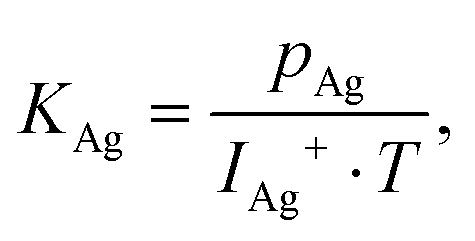
The release mechanism of CsI and CsF fission product compounds from the LiF–ThF4 solvent was studied with a Knudsen effusion cell coupled with a mass spectrometer (KEMS) installed in an alpha-tight and gamma-shielded glove box allowing handling of radioactive materials. During the experiment, the sample was placed in the Knudsen cell made of tungsten metal with a very small orifice on the top, which was placed in the high temperature furnace made of tungsten coil and surrounded by a series of thermal shields. Upon heating, the sample evaporated and the escaping gaseous species were driven through a cross-beam electron bombardment where they were ionized and successively analysed in the quadrupole mass spectrometer. The electron energy used in this study was 29.5 eV, found to be the optimal value to achieve a high signal to background ratio of the analysed intensity. Normally, the vaporization behaviour using the KEMS device is determined at constant heating rate 10 K min−1, but since unique temperature programs had to be applied in the current study to obtain a complete picture of the main findings, the individual temperature programs are described in the respective sub-sections. For more technical details about the KEMS device used in this study one can refer to our previous paper.15The vapour pressure of the molecular species, pi, is determined from the measured intensity of the detected signal according to the general equation:
| pi = Ii+ · T · K, | (1) |
 | (2) |
 | (3) |
 | (4) |
As mentioned earlier, the electron energy used to ionize the molecular gaseous species escaping from the Knudsen cell was 29.5 eV, high enough not only to ionize the species, but also to dissociate the formed molecular species into smaller cations. This phenomenon must be taken into account and the obtained data must be corrected accordingly for the assessment of final partial vapour pressures. Such correction is done by measuring the appearance potential curves at constant temperature. This can be done either during the measurement of the analysed mixture or in the preceding measurements of the end-members, which were necessary to obtain information about the volatility of all components in their pure states. The appearance potential curves for LiF, ThF4 and CsF were measured in our recent studies (ref. 13, 13, and 12, respectively), and since they were measured using the same device keeping the same procedure settings, they were taken into account for the present analysis. The data for the appearance potential of pure CsI were measured in this paper and are presented in Fig. 3.
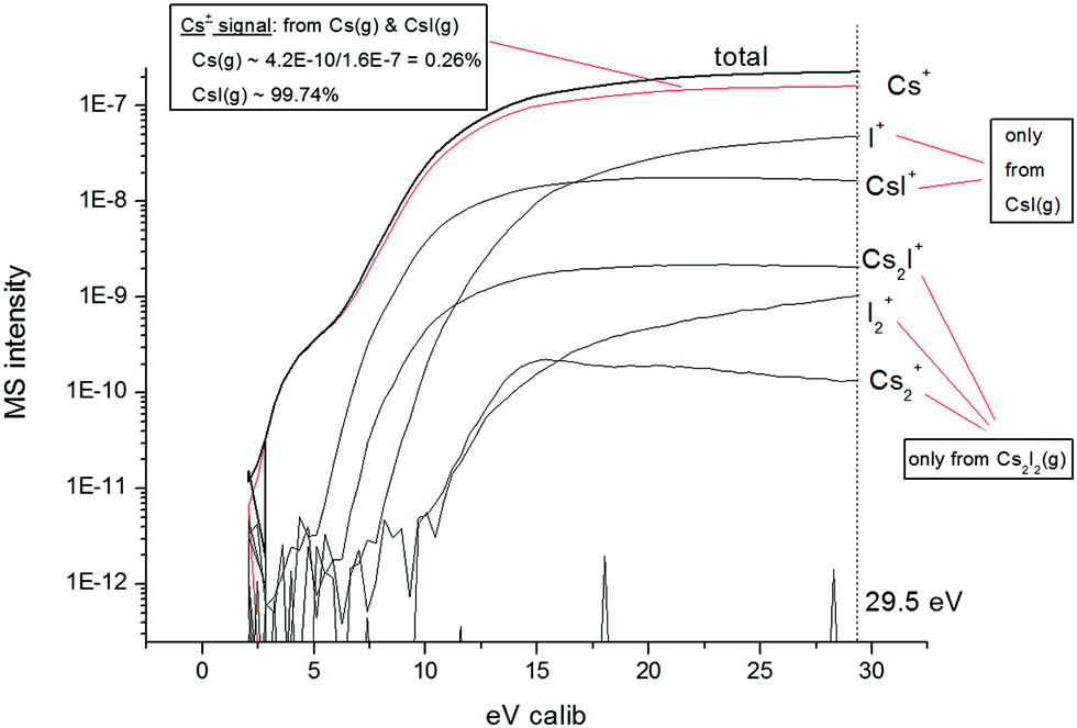 | ||
| Fig. 3 Appearance potential curve measured for the pure CsI compound. | ||
The figure shows that during the evaporation of pure CsI the detected species at the ionization energy of the measurement (29.5 eV) were Cs+, I+, CsI+, Cs2I+, I2+ and Cs2+. From further analysis of the appearance potential curve it was found that 99.74% of the Cs+ signal refers to CsI(g) species, while the remaining 0.26% refers to Cs(g) species. Furthermore, the detected I+ and CsI+ signals refer to the CsI(g) species only and the Cs2I+, I2+ and Cs2+ signals to the Cs2I2(g) dimer. This speciation was taken into account for the quantification of the partial vapour pressure of CsI.
The correction for the dissociation must be treated individually for every system studied by KEMS and is one of the sources of potential uncertainty of the quantified vapour pressure data. With the temperature and ionization calibration performed regularly on the KEMS device and from the performed analysis presented in this study (taking into account the individual ionization potential corrections and the uncertainty of the cross-section determination), we estimate that all vapour pressure data presented in this paper are subjected to an uncertainty of ±20%.
2.3 Differential scanning calorimetry (DSC)
The melting points of the selected sim–fuel mixtures were examined using the differential scanning calorimeter (DSC) detector of a SETARAM multi-detector-high-temperature calorimeter using a B-type sensor with a peak operational temperature of 1600 °C. DSC is a popular thermo-analytical technique in materials science and its principle is based on the measurement of the heat flow between the reference crucible and the crucible filled with the sample during heating or cooling at a specified rate. During the experiment, the reference crucible was kept empty, while the crucible with the sample was a stainless steel crucible with a tightly screwed lid ensuring hermetic tightness during the measurement. An inner liner of nickel inert material was placed in the crucible to avoid any chemical interaction between molten halide salt and the stainless steel. For more details about this encapsulation technique, one can refer to our earlier study.18As the sample started to melt during the heating, a peak was observed on the DSC curve. The phase transition temperature, in this case the eutectic melting, was identified as the onset of the peak.19 A DSC output of the measured LiF–ThF4 (76.5–23.5 mol%) mixture with addition of 1 mol% CsI and the onset point determination are shown in Fig. 4.
 | ||
| Fig. 4 A DSC output of the measurement of the LiF–ThF4 (76.5–23.5 mol%) mixture with addition of 1 mol% CsI. | ||
Before the experiment, a temperature calibration of the instrument was done using a series of reference certified metals with well-defined melting points covering the operational temperature range of the calorimeter from 100 to 1600 °C. The obtained calibration curve was applied to correct the measured temperature as the temperature difference between the position of the sensor and the position of the sample was found due to the kinetics of the heating. As halide salts reveal super-cooling effects during cooling, only the data from the heating cycles were taken into account for melting point determination.
2.4 Scanning electron microscopy
The scanning electron microscope (SEM) used in this study was a Philips XL40, in which the column, chamber and high voltage power supply are mounted inside a glove-box allowing for the measurements of radioactive materials. The EDX detector used for the analyses was an EDAX Si detector with a resolution of better than 0.14 keV, integrated in a SAMx acquisition and software suite. The quantification was made using a ZAF correction method.2.5 ICP-MS
Inductively Coupled Plasma-Mass Spectrometry (ICP-MS) was used to analyse the contents of caesium and/or iodine of the fuel salt mixtures examined by KEMS. A Thermo Fischer Element II instrument was used. The elements were atomised and ionised in high-frequency plasma. After extraction the ions were separated in the mass spectrometer according to their mass-to-charge ratio. The samples analysed by ICP-MS were dissolved in 1 M nitric acid. The measurements were performed according to ISO 17025 standards.3. Thermodynamic simulations
To better interpret the obtained experimental data, a series of thermodynamic calculations were made in this paper. The phase equilibrium determinations were done based on Gibbs energy minimization, according to the so-called CALPHAD method. For all calculations, the commercial FactSage program was used and the input data to determine phase equilibria in the LiF–ThF4–CsF–CsI system were taken from our earlier paper,7 in which the full thermodynamic assessment of this system was made.4. Results
4.1 Melting point determination of the mixtures
As the knowledge of the melting points of both examined mixtures was key to assessing the most appropriate temperature program of the vapour pressure measurement using the KEMS facility, both mixtures were analysed prior to vapour pressure measurement using the DSC technique. The measurement gave insight as well into how much the presence of accumulated fission products affects the melting behaviour of the fuel, a question that is of safety concern.In total, three samples were measured by DSC: the LiF–ThF4 (76.5–23.5 mol%) solvent and their respective CsF- and CsI-containing mixtures. The DSC experiment consisted of three heating (and cooling) runs at a constant heating rate of 10 K min−1. The first run was a homogenization step, whereas the results of the second and third runs were used to determine the melting points.
In the case of the LiF–ThF4 (76.5–23.5 mol%) solvent mixture only a single DSC peak was observed on the DSC heat flow signal, indicating eutectic (or close to eutectic) melting. In the case of the CsI- and CsF-containing sim–fuel mixtures a very similar peak profile was observed, indicating similar, eutectic type, melting behaviour. The melting peak of the DSC heat flow signal of the CsI-containing mixture is given in Fig. 4. The obtained results of the eutectic melting points measured in this study are summarized in Table 1. It is evident that dissolution of CsF in quantities typical for fission yields and very limited dissolution of CsI (note that CsI remains immiscible as discussed above and in Section 4.3) have almost no effect on the melting point of the MSR fuel. We note here that the melting point of phase-separated CsI was not detected due to the small quantity of the sample.
| MSR fuel mixture | Measured eutectic point (K) |
|---|---|
| LiF–ThF4 (76.5–23.5 mol%) | 839.1 ± 5 |
| LiF–ThF4 (76.5–23.5 mol%) + 1 mol% CsF | 838.3 ± 5 |
| LiF–ThF4 (76.5–23.5 mol%) + 1 mol% CsI | 833.3 ± 5 |
4.2 Release of CsF from LiF–ThF4
The first investigated system was 1 mol% CsF added to LiF–ThF4 (76.5–23.5 mol%). The mixture was prepared in proportional weights in the solid state and prior to the KEMS experiment homogenized by melting all components together in a hermetically closed crucible which avoided evaporation of CsF or any other components. About 50 mg sample was examined by KEMS and the vapour pressures of all three components were measured as functions of temperature. The temperature program of the measurement consisted of two parts: (i) rapid heating at a rate of 100 K min−1 to 900 K, thus with a sufficient margin above the melting point of the mixture; and (ii) successive heating at a constant heating rate of 10 K min−1 for the determination of the retention capacity of the molten fuel. The rapid heating program was needed to avoid (or suppress) CsF evaporation from the solid state as the vapour pressure of pure CsF is significantly higher compared to the LiF and ThF4 matrix components, as shown in Fig. 1. Reaching the temperature region well above the melting point ensured that the added quantity of CsF fully dissolved in the molten fuel matrix as no indications of pre-release of CsF was found on the mass spectrometry signal during the rapid heating sequence. This observation is in agreement with our previous comprehensive study of the CsF–ThF4 system.12 The small bump observed for the CsF(g) and Cs(g) signals slightly above 900 K evident in Fig. 5 was due to the unstable temperature of the liquid nitrogen cooled cold-trap and related distorted vacuum. A similar bump above 900 K was also observed on the ThF4 signal. | ||
| Fig. 5 Output of volatility measurements of 1 mol% CsF mixed with the LiF–ThF4 (76.5–23.5 mol%) matrix (associated signals from the figure: LiF, CsF, Cs, ThF4) compared with measurements of: (i) the pure CsF compound (associated signals from the figure: CsFPure,m, CsPure,m) (compared with thermodynamic calculations (CsFFS) and experimental data from the literature (CsFLit.)20) and (ii) the LiF–ThF4 (80–20 mol%) fuel matrix taken from ref. 13 (associated signals from the figure: LiF80, ThF4,20). | ||
The quantified vapour pressures of CsF, LiF and ThF4 measured in this paper are reported in Fig. 5, and to assess the retention capacity of the MSR fuel towards the CsF fission product form, the data were compared to the vapour pressure of the LiF–ThF4 (80–20 mol%) mixture measured earlier by Capelli et al.,13 calculated pure CsF vapour pressure,9 vapour pressure measurements of pure CsF from our earlier study12 and experimental data from Eisenstadt et al.20
Fig. 5 shows that CsF(g) and Cs(g) arising from CsF dissolved in the salt show even about 10 times lower release compared to LiF(g), strongly suggesting CsF retention within the fuel salt. Furthermore, the vapour pressure of pure CsF agrees well among all data and is orders of magnitude above the CsF(g) vapour pressure of the sim–fuel mixture, confirming that the CsF is dissolved in the solution (otherwise CsF(g) would be of the same order). The smooth release of CsF(g) and Cs(g) species, which starts around 950 K and follows release of the LiF and ThF4 matrix components, is another confirmation of CsF dissolution in the sim–fuel melt. The drop of the CsF-species related vapour pressure signals is due to the much lower initial quantity of CsF compared to LiF and ThF4.
The quantification of the CsF(g) vapour pressure indicates that the volatility of 1 mol% of CsF dissolved in the MSR fuel based on the LiF–ThF4 matrix is about 200–300 times lower compared to CsF in the pure form. The signals of LiF(g) and ThF4(g) are very close to the respective vapour pressures of the LiF–ThF4 (80–20 mol%) solvent mixture of similar composition measured earlier,13 indicating no influence of CsF on the vapour pressure of the mixture. This observation is in line with a rather small initial concentration of CsF.
4.3 Release of CsI from LiF–ThF4
The cationic species detected during the measurement were Cs+, Cs2+, CsI+, I+, Cs2I+ and CsI2+. Unfortunately, we could not detect the Cs2I2+ signal, as the corresponding atomic mass unit of this species was just above the limit of the used mass spectrometer. However, we note that such an instrumental limitation does not significantly affect the main findings of the present study for the following main reasons: (i) the ‘missed’ Cs2I2+ signal can only be associated with the Cs2I2(g) dimer that has much lower pressure compared to the CsI(g) monomer; (ii) the retention capacity which is the main concern of the study can be demonstrated by comparison of monomer behaviour only (as mostly done in this study as discussed further throughout Section 4.3); and (iii) at an ionization energy of 29.5 eV, significant dissociation of larger molecules (as e.g. the Cs2I2(g) dimer) occurs so the Cs2I2+ signal becomes less relevant for the data interpretation. The vapour pressure analysis accounting for the dissociation of CsI and Cs2I2 gaseous species is provided in Section 2.2, in which the measured appearance potential curve was presented (Fig. 3). The results of the vapour pressure measurements of pure CsI obtained in this paper are shown in Fig. 6 and compared with available data from the literature assessed by Roki et al.8 and with complementary thermodynamic calculations performed in this study.
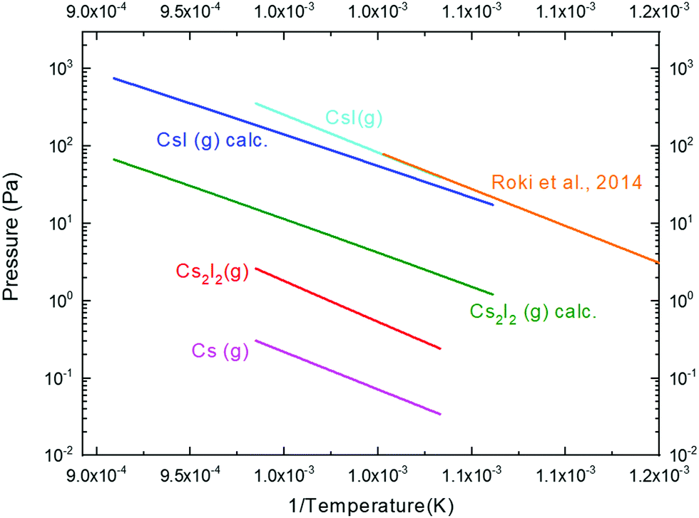 | ||
| Fig. 6 Measured partial vapour pressures of pure CsI compared with calculated values (denoted as calc.) and review work by Roki et al.8 | ||
The values of the partial vapour pressure of the CsI(g) monomer are in a very good agreement with the literature data by Roki et al. as well as with the calculated data. This is, however, not the case for the dimer. The measured partial vapour pressure data of the Cs2I2(g) dimer are somewhat lower compared to the calculated ones, and among the possible reasons might be the detection issue of the Cs2I2+ species which is above the limit of the mass spectrometer as mentioned earlier. On the other hand, at 29.5 eV ionization energy the intensity of such high-mass species is not likely to be very high, as at such high energy the Cs2I2(g) is significantly dissociated. Nevertheless, since the CsI(g) monomer is the major vapour species of the CsI compound, the measurement of the retention of CsI in the molten salt reactor fuel mainly depends on the correct quantification of this species.
 | ||
| Fig. 7 Output of volatility measurements of 1 mol% CsI mixed with the LiF–ThF4 (76.5–23.5 mol%) matrix (associated signals from the figure: LiF, CsI, Cs, ThF4) compared with measurements of (i) pure CsI (CsIPure,m) (including thermodynamic calculations (CsIFS)) and (ii) the LiF–ThF4 (80–20 mol%) fuel matrix taken from ref. 13 (associated signals from the figure: LiF80, ThF4,20). | ||
It is evident from the figure that CsI release was very different from that observed in the case of CsF. A major CsI release was found above 900 K, almost reaching the vapour pressure values of pure CsI. At around 1000 K a sudden drop was observed, most likely because all CsI evaporated at that point, and once the vaporization of the matrix components increased, the signature of slight second release was found in the vapour pressure curves of CsI. Since the second release was of very low intensity, it was very difficult to judge if that release occurred or if it was a high temperature background effect. For that reason, a separate experiment was performed, quenching the sample after the first major release and subjecting it to chemical analysis, as discussed below. Nevertheless, the presence of the first significant release indicates that no or very little CsI was dissolved in the LiF–ThF4 fuel matrix. Such observation was confirmed by thermodynamic calculations by Capelli et al., as discussed in the Introduction section. To understand if kinetics might be responsible for such poor dissolution, we performed another experiment using early encapsulation of the sample to allow a longer time to fuse all salt components together before the release measurement.
For such experiments a crucible from silver metal was selected, and once the sample was placed inside, the crucible was encapsulated using laser welding. Silver was found to be an ideal candidate, as it is used as a reference material for mass spectrometer calibration, and it was found to be inert to molten fluoride salts (we never observed artefacts on the silver vapour pressure curves which would be due to chemical interaction between the salt and silver). Another criterion fulfilled by silver is the melting point, which is high enough to mix all three components in the molten state, i.e. the melting point of silver (Tm = 1235 K) is higher than the eutectic temperature of the mixture, determined by DSC and reported in Table 1 (Teut. = 833.3 K). On the other hand, silver melts at low enough temperature to allow release measurement of the selected salt under the so-called Knudsen conditions, i.e. to distinguish between kinetic burst and vaporization driven by a thermodynamic equilibrium.
The KEMS temperature program for the sample encapsulated in the silver crucible consisted of three steps: (i) fast heating at a rate of 100 K min−1 to reach a temperature of ∼1200 K, i.e. below the melting point of silver; (ii) dwelling at 1200 K for 3 h to allow enough time to homogenize the melt; and (iii) release measurement at a rate of 10 K min−1. The early fast heating during the first step had no other meaning than to spare time for the complete experiment as the whole procedure must fit in one working day. Results obtained from the third step corresponding to the release measurement are shown in Fig. 8, highlighting the temperature range close to silver melting. It is evident from the figure that once silver melts at 1235 K, the vaporisation of all three components increases by orders of magnitude, as seen from the sudden increase of the intensity of the detected vapour species. Furthermore, it is shown that both LiF(g) and ThF4(g) gaseous species quickly reach their equilibrium vapour pressure values, and with further temperature increase, their vapour pressures also increase constantly. The case is different for the CsI(g) signal, which right after the melt of the crucible increases, but almost immediately drops down, clearly indicating that CsI is poorly soluble in the LiF–ThF4 salt and thus evaporates instantly. A similar conclusion was derived in the work of Sekiguchi et al.21 studying CsI behaviour in the FLiNaK salt (eutectic composition of the LiF–NaF–KF system).
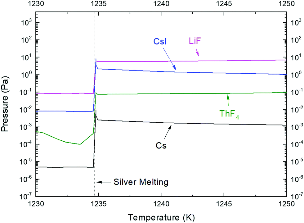 | ||
| Fig. 8 Vapour pressure measurement of the 1 mol% CsI mixed with the LiF–ThF4 (76.5–23.5 mol%) matrix in the region of silver crucible melting. | ||
As in the case of CsF, the presence of CsI did not influence the vaporization behaviour of the LiF–ThF4 fuel matrix, which is again evident from comparison to the vapour pressure data of the LiF–ThF4 (80–20 mol%) mixture measured earlier by Capelli et al.,13 as almost identical behavior was observed, as shown in Fig. 7.
 | ||
| Fig. 9 Selected SEM/EDX images of the eutectic LiF–ThF4 with 1 mol% of CsI sample measured by KEMS up to 980 K and subsequently quenched to room temperature. The picture shows observations from three different sample locations (horizontal alignment); SE stands for secondary images; Cs, I and Th stand for images showing the visual intensities of the respective atoms. All images are obtained with 800× magnification. | ||
| ID | Area | Mag. | Element | Int. | Wt% | At% |
|---|---|---|---|---|---|---|
| 8420 | Centre | 800× | I | 0 | 0 | 0 |
| Cs | 2.9 | 1.7 | 0.7 | |||
| Th | 228.1 | 68.41 | 16.12 | |||
| 8426 | Border right | 800× | I | 0 | 0 | 0 |
| Cs | 1.1 | 1.07 | 0.47 | |||
| Th | 151.2 | 71.45 | 17.96 | |||
| 8437 | Top right | 800× | I | 0 | 0 | 0 |
| Cs | 4.5 | 2.21 | 1.06 | |||
| Th | 293.3 | 73.2 | 20.15 |
To confirm the SEM/EDX observation, an independent chemical analysis using ICP-MS was done on the same quenched sample. The results from the ICP-MS analysis confirmed the absence of iodine, but confirmed the presence of caesium. Unfortunately, quantification of the remaining caesium concentration was not possible.
The slight increase of the CsI(g) and Cs(g) signals in the high temperature region of the KEMS experiment (as shown in Fig. 7) might be due to the relatively high pressures of other fuel components, which increase the vacuum background levels of the mass spectrometric signal.
SEM images of the sample with selected magnifications are shown in Fig. 10. In the SEM images on the right (5000×) the particles of LiF/ThF4 and CsI are clearly visible. Chemical analysis of the particles was done by coupling SEM with EDX techniques, as shown in Fig. 11. The images in the first row of the figure correspond to a magnification of 500×, while those in the bottom row correspond to a magnification of 800×. Unfortunately, it was not possible to detect LiF because both Li and F are too light and not suitable for EDX detection. However, there is strong evidence, e.g. the binary phase diagram,3 to assume that in the molten state LiF is homogeneously mixed with ThF4. The EDX mapping shown in Fig. 11 clearly indicates that CsI is not mixed with the rest of the sample, as the mapping identifying Th (right picture of Fig. 11) is bright exactly where the mapping of Cs and I is dark.
 | ||
| Fig. 10 SEM images of the LiF–ThF4 eutectic with 1 mol% of CsI after melting in a DSC crucible. Each horizontal series corresponds to a different sample location; left figures correspond to 50× magnification; middle figures to 500× magnification and right figures to 5000× magnification. | ||
 | ||
| Fig. 11 Mapping of the LiF–ThF4 eutectic with 1 mol% of CsI after melting in a DSC crucible using the EDX technique. The picture shows observations from two different sample locations (horizontal alignment); SE stands for secondary images; and Cs, I and Th stand for images showing the visual intensities of the respective atoms. The upper series correspond to 500× magnification, while the lower series correspond to 800× magnification. | ||
The quantitative chemical analysis of the mapped regions shown in Fig. 11 is given in Table 3. The two zones analysed are in good mutual agreement and both show significant quantities of I and Cs with close to 1![[thin space (1/6-em)]](https://www.rsc.org/images/entities/char_2009.gif) :1 molar ratios, while the concentration of Th is very low.
:1 molar ratios, while the concentration of Th is very low.
| ID | Mag. | Element | Intensity | Weight% | Atomic% |
|---|---|---|---|---|---|
| 8396 | 500× | I | 206.2 | 38.8 | 27.28 |
| Cs | 175.6 | 35.44 | 23.79 | ||
| Th | 84.8 | 12.81 | 4.93 | ||
| 8403 | 800× | I | 228.5 | 37.31 | 25.32 |
| Cs | 193.9 | 34.02 | 22.04 | ||
| Th | 116.6 | 15.05 | 5.59 |
5. Discussion
In the present study we focused on two probable chemical forms of two highly relevant fission products, Cs and I, and their vaporization behavior from molten salt reactor fuel. From the obtained results it was clearly demonstrated that while CsF is fully soluble in the fluoride based MSR fuel, the contrary is true for CsI. The latter conclusion was not only confirmed by the performed KEMS analysis, but also by SEM/EDX chemical mapping of the quenched sample. In terms of limited CsI solubility, this study confirmed earlier predictions based on thermodynamic equilibrium calculations done by Capelli et al.Putting the thermodynamic data into context with the obtained experimental results, a strong correlation was obtained. In the case of 1 mol% of CsF added to the LiF–ThF4 (76.5–23.5 mol%) fuel, the calculated vapour pressure of CsF ranges from very low 2.6 × 10⁻⁴ Pa at 900 K to 0.2 Pa at 1200 K, in excellent agreement with our experimental findings, as e.g. depicted in Fig. 5. Furthermore, the LiF–ThF4 phase diagram with a fixed concentration of CsF of 1 mol% was calculated, and as shown in Fig. 12a, it confirms the complete solubility of CsF in the LiF–ThF4 solvent as no miscibility gap is found in the liquid region. A similar phase diagram was calculated for addition of 1 mol% of CsI, and the results are given in Fig. 12b. In this case, a clear large immiscible region is found in the liquid solution, which explains the limited solubility of CsI in the LiF–ThF4 based solvent resulting in higher volatility. The calculated vapour pressure of CsI(g) from the LiF–ThF4 (76.5–23.5 mol%) fuel solvent was found to be 4.5 Pa at 900 K, increasing to 560 Pa at 1200 K. In comparison, the vapour pressure of pure CsI was 16 Pa at 900 K, increasing to 3000 Pa at 1200 K. A comparison of these two calculated values is very well correlated with our experimental observations using the KEMS technique (Section 4.3.1), which suggested only a small drop of CsI vapour pressure from the fuel mixture compared to pure CsI. From this, we can conclude that although CsI has very limited solubility in the LiF–ThF4 fuel, a small effect on vapour pressure is evident, but much lower compared to the CsF.
 | ||
| Fig. 12 (a) A calculated LiF–ThF4 phase diagram with a fixed concentration of CsF of 1 mol%. (b) A calculated LiF–ThF4 phase diagram with a fixed concentration of CsI of 1 mol%. | ||
Furthermore, the results of the current study strongly indicate a partial exchange reaction of CsI into another, most likely soluble form, which is of fluoride based chemical nature. This observation was confirmed by chemical analysis of the quenched CsI–LiF–ThF4 sample performed using SEM/EDX, complemented with the ICP-MS method. Both techniques showed the obvious presence of cesium, whereas no traces of iodine were found. Since the simple possible exchange reactions such as
| CsI + LiF → LiI + CsF | (R1) |
| 4CsI + ThF4 → ThI4 + 4CsF | (R2) |
• A miscibility gap in the liquid solution was found at 980 K (as shown in Fig. 12b).
• The calculated compositions of two liquids in equilibrium at 980 K and their total quantities are (all numbers are in mol%):
L1 (94.1 mol%): LiF (76.1); ThF4 (23.3); CsF (0.35); CsI (0.0007); LiI (0.16); ThI4 (0.05)
L2 (5.9 mol%): LiF (62.2); ThF4 (20.6); CsF (10.4); CsI (0.75); LiI (4.5); ThI4 (1.5)
• The values given in the bullet point above confirmed the partial formation of Li- and Th-based iodides in the molten fluoride environment, as well as the formation of CsF, which was further dissolved in the fuel (was retained).
• It was confirmed that a very limited solubility of CsI is achieved in the LiF–ThF4 solvent.
• The vapour pressure at 980 K was dominated by CsI(g) (25 Pa), with LiI(g) (2.8 Pa) as the second largest contributor. We accentuate that both volatile species carried iodine, whereas only one contained cesium.
All the above summarized conclusions explain that there is indeed a partial exchange reaction possible between CsI and fluoride based solvent and this very well explains why no iodine was found in the quenched sample, while traces of Cs (most likely stabilized as CsF) remained dissolved.
Assuming that the source term of fission products would be mainly driven by their volatilities, one can assess the source term reduction from the results obtained in this study. For simplification purposes, the reduction of the source term of caesium and iodine is graphically represented in Fig. 13 by plotting the calculated vapour pressures of Cs- and I-related species on a logarithmic scale with reference to the elemental forms. The green arrows indicate the importance of two factors: (i) the chemical form in which the fission product will stabilize, and (ii) whether that chemical form is soluble in the fuel matrix or not. The graph assumes nominal concentrations of Cs and I of 1 mol% and summarizes the main findings of this study, which are discussed further in detail.
 | ||
| Fig. 13 Graphical assessment of the release potential (pressure) of iodine and caesium in their nominal concentrations of 1 mol% from LiF–ThF4 MSR fuel solvent at 1123 K based on the volatility of CsI and CsF components. The dot in the figure corresponds to the experimental value determined by the KEMS experiment. | ||
For the discussion it is important to realise that the average fission yield of cesium in nuclear fuel is about 10× higher compared to iodine. Whether cesium will preferentially react with iodine to form iodide or with fluorine to form fluoride will depend on the actual values of the fluorine and iodine potentials, as already demonstrated in Fig. 2. The chemical form in which iodine stabilized was extensively studied during the Molten Salt Reactor Experiment program at Oak Ridge National Laboratory,22 concluding that most of the iodine would become iodide (I−) and the remaining iodine, which is a daughter product of xenon gas, would be stripped away through a sparging system (e.g. online helium bubbling) and treated as waste.
Now, assuming the worst case, i.e. the thermodynamic preference in the Cs–I–F system will be given to the formation of poorly soluble CsI rather than CsF, the resulting ratio that would stabilize in the fluoride based MSR fuel would be 1 part of CsI and 9 parts of CsF (neglecting the iodine stripped away by online clean-up). Starting from the elemental forms of Cs and I, which are formed upon fission of actinides and following the green vertical arrow, which represents the source term at a selected temperature 100 °C higher than the upper operating temperature limit of the MSFR,4 the figure highlights how the chemistry influences the release based on volatility. The figure clearly shows that just the stabilization of iodine in the form of iodides at 1123 K results in 100× lower release potential compared to the elemental form. A further decrease of the iodine pressure is due to the partial solubility of iodides in fluoride salt media, but as shown in this paper, the solubility is very low and therefore the effect on the vaporization behavior is very low too. According to the results of this study, the final pressure of iodine compared to the elemental form will be 200–300× lower. The same relative drop is expected for cesium arising from CsI.
Since cesium most likely stabilizes as CsF, the source term reduction will be much bigger due to its complete solubility in the fluoride based MSR fuel. The decrease of the volatility indicated in Fig. 13 is again represented by two green arrows, with the first one showing the drop due to chemical stabilization in the cesium fluoride form, while the second and larger one is due to high solubility, and related retention in the fuel. The source term of Cs arising from CsF was assessed based on the present study – neglecting kinetic effects – to be 2 × 10⁵ times lower compared to the volatility of its elemental form. It is important to note that such a value corresponds to simulated initial 1 mol% of CsF, but the value corresponding to real reactor conditions might be even lower, while in case the volatility is given by the total amount dissolved in the fuel, it is at the same time proportional to concentration.
6. Conclusions
Several key conclusions related to the understanding of the retention capacity of fluoride-based molten salt reactor fuel with respect to fission products were drawn based on the results of this paper. Firstly, it was demonstrated that the chemistry of the fission products plays a key role in determining their volatility during high temperature events. It is very likely that due to the molten state of the fuel and the thus related high mobility of the cations, the thermodynamically stable form will be quickly bonded in the MSR fuel, as opposed to solid oxide fuels, in which some fission products are non-bonded and the retention is due to the fact that the solid matrix inhibits cation (fission product) migration within the fuel pellet. Secondly, the study clearly showed that if the fission product cesium was stabilized in the fluoride fuel in the chemical form of CsF, it would remain dissolved in the composition range typical for an average fission product yield. Consequently, the volatility of the thus dissolved CsF would be significantly lower compared to pure CsF and would considerably contribute to lower cesium release during a high temperature event. To quantify, the present study showed that 1 mol% of dissolved CsF has about 200–300 times lower volatility than CsF in the pure state (i.e. not part of the matrix). On the other hand, the fission product iodine is less well bonded in the MSR salt due to the very limited solubility of iodides in the fuel matrix. If it associates with cesium, CsI will form, and if the solubility limit (still to be determined experimentally) is exceeded, its volatility will be close to that of pure CsI. Hence, the release of iodine will not be affected to the same extent as in the case of CsF; however, the fact that the formed iodine stabilizes as iodide (most likely catching an alkali metal) and thus does not remain in the much more volatile elemental form reduces the iodine source term considerably. Furthermore, fission yield calculations suggested that about 10 times more cesium was formed than iodine. This means that even if all (or almost all) iodine would preferentially react with cesium to form CsI, which remained in large quantities undissolved, the remaining cesium (9 parts from 10) would most likely stabilize in the form of dissolved CsF in the MSR fuel (being retained in the MSR fuel). Furthermore, elemental analysis of the quenched samples of the KEMS experiment evidenced that exchange reaction between CsI and the fluoride fuel matrix took place as no iodine was found in the quenched sample, whereas cesium was observed. The interpretation of these results clearly demonstrated the importance of the correlation between experimental studies and e.g. thermodynamic simulations, as it leads to better understanding of the fundamentals of the fuel behaviour. Finally, a complementary calorimetric analysis of the sim–fuel samples showed that the presence of CsF and CsI in small quantities (≤1 mol%) has almost no effect on the melting temperature of the MSR fuel.7. Outlook
This paper showed a clear difference in volatility behavior of individual CsF and CsI chemical forms dissolved in the selected MSR fuel. Besides that, we further showed that exchange reaction between the CsI and fluoride matrix components takes place. To further explore the study and support these key findings, it would be essential to perform similar studies in the future on higher-order systems including mixtures of CsF and CsI and possibly of LiI and ThI4. Focusing on concentration variations would help in predicting the vaporization behavior typical for the concrete MSR concept. The experimental findings should be correlated with experimental data on the volatility behavior of these fission products from irradiated MSR fuel.8. Summary
The present study showed that the volatility of Cs in the fluoride based MSR fuel can be 3 to 4 orders of magnitude lower compared to the elemental form.Similarly, the volatility of I arising from CsI in the fluoride based MSR fuel can be about 2–3 orders of magnitude lower compared to the elemental form.
Data availability
The raw/processed data required to reproduce these findings cannot be shared at this time due to technical or time limitations.Conflicts of interest
There are no conflicts to declare.Acknowledgements
The authors would like to acknowledge the Analytical Service of JRC for the ICP-MS analysis of the selected samples. The HORIZON2020 EU-project SAMOFAR (grant agreement ID: 661891) is acknowledged for substantial financial support to perform the work.References
- H. Kleykamp, J. Nucl. Mater., 1985, 131, 221–246 CrossRef CAS.
- R. J. M. Konings, T. Wiss and O. Beneš, Predicting material release during a nuclear reactor accident, Nat. Mater., 2015, 14, 247–252 CrossRef CAS PubMed.
- E. Capelli, et al., Thermodynamic investigation of the LiF–ThF4 system, J. Chem. Thermodyn., 2013, 58, 110–116 CrossRef CAS.
- D. Heuer, et al., Towards the thorium fuel cycle with molten salt fast reactors, Ann. Nucl. Energy, 2014, 64, 421–429 CrossRef CAS.
- HORIZON2020 EU-Project SAMOFAR, grant agreement ID: 661891.
- C. Margheritis, G. Flor and C. Sinistri, Miscibility Gaps in Fused Salts, Z. Naturforschung A, 1973, 28A, 1329–1334 CrossRef.
- E. Capelli, O. Beneš and R. J. M. Konings, Thermodynamics of soluble fission products cesium and iodine in the molten salt reactor, J. Nucl. Mater., 2018, 501, 238–252 CrossRef CAS.
- F.-Z. Roki, et al., Critical assessment of thermodynamic properties of CsI solid, liquid and gas phases, J. Chem. Thermodyn., 2014, 70, 46–72 CrossRef CAS.
- M. W. Chase Jr., NIST-JANAF Thermochemical Tables (Fourth Edition). Monograph No. 9, 1998, Journal of Physical and Chemical Reference Data Search PubMed.
- C. W. Bale, E. Bélisle, P. Chartrand, S. A. Decterov, G. Eriksson, A. E. Gheribi, K. Hack, I. H. Jung, Y. B. Kang, J. Melançon, A. D. Pelton, S. Petersen, C. Robelin, J. Sangster, P. Spencer and M.-A. Van Ende, FactSage thermochemical software and databases – 2010–2016, Calphad, 2016, 54, 35–53 CrossRef CAS.
- E. Capelli, O. Beneš and R. J. M. Konings, Thermodynamic assessment of the LiF–ThF4–PuF3–UF4 system, J. Nucl. Mater., 2015, 462, 43–53 CrossRef CAS.
- N. Vozárová, et al., Thermodynamic determination and assessment of the CsF–ThF4 system, J. Chem. Thermodyn., 2017, 114, 71–82 CrossRef.
- E. Capelli, et al., Determination of the thermodynamic activities of LiF and ThF4 in the LixTh1–xF4–3x liquid solution by Knudsen effusion mass spectrometry, Phys. Chem. Chem. Phys., 2015, 17, 30110–30118 RSC.
- P. Souček, et al., Synthesis of UF4 and ThF4 by HF gas fluorination and re-determination of UF4 melting point, J. Fluorine Chem., 2017, 200, 3340 CrossRef.
- J. Y. Colle, et al., Knudsen effusion mass spectrometry of nuclear materials: Applications and developments, ECS Trans., 2013, 46, 23–38 CrossRef.
- R. Hultgren, et al., Selected values of the thermodynamic properties of the elements, American Society for Testing and Materials, 1973 Search PubMed.
- D. W. Bonnel, Program Sigmas, NIST, USA, 1990 Search PubMed.
- O. Beneš, et al., A DSC study of the NaNO3–KNO3 system using an innovative encapsulation technique, Thermochim. Acta, 2010, 509(1), 62–66 CrossRef.
- G. W. H. Höhne, W. Hemminger and H.-J. Flammersheim, Differential Scanning Calorimetry, Springer Berlin, Heidelberg, 1996 Search PubMed.
- M. Eisenstadt, G. Rothberg and P. Kusch, Molecular composition of alkali fluoride vapors, J. Chem. Phys., 1958, 29(4), 797 CrossRef CAS.
- Y. Sekiguchi, et al., Fundamental study on the vaporization of cesium and iodine dissolved in LiF–NaF–KF molten salt, J. Nucl. Mater., 2019, 522, 136–143 CrossRef CAS.
- E. L. Compere, et al., Fission Product Behavior in the Molten Salt Reactor Experiment, Oak Ridge, TN, 1975 Search PubMed.
| This journal is © the Owner Societies 2021 |