
Phase evolution of Cu2ZnSnS4 (CZTS) nanoparticles from in situ formed binary sulphides under solvothermal conditions†
Rameez
Ahmad
ab,
Naeem-ul-Hasan
Saddiqi
ab,
Mingjian
Wu
 cd,
Mirko
Prato
e,
Erdmann
Spiecker
cd,
Wolfgang
Peukert
ab and
Monica
Distaso
*ab
cd,
Mirko
Prato
e,
Erdmann
Spiecker
cd,
Wolfgang
Peukert
ab and
Monica
Distaso
*ab
aInstitute of Particle Technology, Friedrich-Alexander-Universität Erlangen-Nürnberg (FAU), Cauerstraße 4, 91058 Erlangen, Germany. E-mail: monica.distaso@fau.de
bInterdisciplinary Center for Functional Particle Systems, Friedrich-Alexander-Universität Erlangen-Nürnberg (FAU), Haberstraße 9a, 91058, Erlangen, Germany
cInstitute of Micro- and Nanostructure Research and Center for Nanoanalysis and Electron Microscopy (CENEM), Friedrich-Alexander-Universität Erlangen-Nürnberg (FAU), Cauerstraße 3, 91058 Erlangen, Germany
dInterdisciplinary Center for Nanostructure Films (IZNF), Friedrich-Alexander-Universität Erlangen-Nürnberg (FAU), Cauerstraße 3, 91058 Erlangen, Germany
eMaterials Characterization Facility, Istituto Italiano di Tecnologia (IIT), Via Morego 30, 16163 Genoa, Italy
First published on 20th May 2021
Abstract
Cu2ZnSn(S,Se)4 (CZTSSe) are benign and low-cost materials, overcoming the limitations of toxicity and high costs of other semiconductors such as CuInGa(S,Se)2, cadmium and lead chalcogenides, and Pb-based perovskites widely used in photovoltaic and thermoelectric applications. In order to shed light on the formation mechanism of CZTS nanoparticles using anisole as the solvent, oleylamine as the organic ligand, carbon disulphide as the sulphur source and Zn(NO3)2·6H2O as the Zn(II) precursor, we follow the conversion of binary sulphides formed in situ under solvothermal conditions into quaternary phases. Besides a careful microstructural characterization of the as-synthesized materials by X-ray diffraction (XRD), Raman spectroscopy, electron microscopy (TEM and HRTEM) and energy dispersive X-ray (EDX) spectroscopy at micron- and nano-scale, we study the evolution of particle surface properties by X-ray-photoelectron spectroscopy (XPS). The results show that CZTS particles form already during the early stages of the reaction, most probably through a nucleation and growth mechanism. In parallel, a comparably slower growth mechanism is observed that involves recrystallization between the binary phases, without evidence of ternary phase formation.
1. Introduction
Quaternary chalcogenides based on Cu, Zn, Sn and S and/or Se (CZTS and CZTSSe) are a class of benign and low-cost materials, which find applications in thin film solar cells,1 as photocatalysts for solar water splitting,2–4 as microwave absorbers,5 and in magneto-optic, magnetoferroic, and thermoelectric applications.6 This intriguing class of materials represents a valuable alternative to other technologically established semiconductors based on Pb, Ga and In, elements that are classified as critical by the European Community.7 The advancements in the syntheses of CZTSSe nanoparticles have provided general designing rules for the selection of the right precursors toward hexagonal, cubic or tetragonal phase, the suppression of secondary phase formation (binary and ternary compounds) and the control over defect distribution.8–18 However, in-depth mechanistic understanding of CZTS particle formation is far from being achieved, although this knowledge could contribute to overcoming the current limit of solar cell efficiency (11–13%) and enable the exploitation of CZTS materials in other technological fields. For instance, one open question is whether CZTS particles nucleate and grow as a single phase, or rather the final quaternary phase results from complex equilibria between binary and ternary phases and molecular precursors. This is an important question because the size, shape and crystallinity of binary sulphides can be controlled by separating the nucleation event from the growth step following well-established synthetic strategies,19 whereas the engineering of multicomponent materials such as kesterite and chalcopyrite arising from binary and ternary phases is still under development. Accordingly, the CZTS phase is more likely to nucleate and grow in hot-injection processes20,21 or by thermal decomposition of dithiocarbamates (DTCs),22,23 xanthate24 complexes of the metals, or single molecular precursors.25,26 Such complexes can also be generated in situ between the inorganic salts, the organic ligands and the sulphur precursor, respectively, in the so-called one-pot heating up methods.17,18,27 These synthesis conditions are particularly appealing because they do not require pre-synthesizing the molecular precursors and are highly reproducible and scalable, especially for longer reaction times, provided that both the heating and the cooling ramp can be externally controlled. Nevertheless, the exact formation pathway is highly dependent on the molecular precursors used. Recently, we have reported that under solvothermal conditions the quaternary CZTS phase forms already at low temperature (200 °C) and short reaction time (2 h) when acetate salts are used as precursors, whereas the use of chloride salts leads to the formation of the ternary Cu–Sn–S (CTS) phase, without incorporation of Zn, even at higher temperature (250 °C) and longer reaction time (24 h).18 This behaviour has been attributed to the coordination of chloride ions onto the surface of ZnS nanoparticles and rationalized using the Pearson theory of hard and soft acids and bases (HSAB).18 A robust method to achieve CZTSSe layers implies the deposition of pre-synthesized binary and ternary sulphide nanoparticulate inks onto a suitable substrate, followed by evaporation of the solvent, annealing under a controlled atmosphere and selenization.28–32 While this solid phase route is widely explored, the conversion of binary to quaternary sulphides in the liquid phase has been poorly investigated, although this is an important underlying formation mechanism. Therefore, in the current paper, inorganic salts are selected that mainly lead to binary sulphides besides small amounts of CZTS particles during the early stages of particle formation. The formation pathway of CZTS nanoparticles is investigated as a function of time and temperature, showing that longer time and higher temperature are necessary to convert the in situ generated binary sulphides to the quaternary CZTS phase without evidence of intermediate ternary phase formation.2. Experimental details
2.1 Synthesis of particles under solvothermal conditions
All chemicals were used as received without any further purification. Anisole (≥99%, Sigma Aldrich, Germany), methanol (95.5%, Carl-Roth, Germany) and toluene (95.5%, Carl-Roth, Germany) or chloroform (≥99%, Carl-Roth, Germany) were used as the solvent and for washing and dispersion purposes, respectively. Oleylamine (70% OLA) was a Sigma Aldrich product. Carbon disulphide (≥99%, Sigma Aldrich, Germany) was used as the sulphur source. Cu(II) nitrate trihydrate and Zn(II) nitrate hexahydrate were purchased from Sigma Aldrich (99.95%, Germany). Sn(IV) acetate (98%) was acquired from Alfa Aesar, Germany. In a typical synthesis, 0.8 mmol of Cu(II) nitrate trihydrate, 0.4 mmol of Zn(II) nitrate hexahydrate and 0.4 mmol of Sn(IV) acetate were added to 40 mL of anisole. The suspension was stirred at 400 rpm for 10 minutes at 35 °C, whereby partial solubilisation was observed. After the addition of oleylamine (OLA, 1.7 mL, 5.17 mmol) and mixing for 10 minutes, the dissolution of salts and the formation of a blue, transparent solution was observed. The sulphur source CS2 (8 mmol, 480 μL) was then added to the solution which immediately turned yellow-brown. The formation of solid was not observed at room temperature. The homogeneous solutions were then transferred to a Teflon liner with a volume of 250 mL and heated up to 200 °C (for 2 and 24 hours) or 250 °C (for 2, 4, 8 and 24 hours) using a stainless steel DAB3 autoclave from Berghoff GmbH (Germany) equipped with an aluminium block ring placed on a heating plate. Reactions shorter than 2 h were not investigated, whereas 2 h was identified as the starting point for the current kinetic study because the relatively slow heating and cooling profiles for shorter reaction times would make the assessment of the actual reaction temperature and time unreliable (Fig. S1, ESI†). After the given time, the autoclave was allowed to cool naturally for an additional four hours until the temperature was below 50 °C. After the reaction, the suspension was centrifuged to separate the particles from the mother liquor at a relative centrifugal force (RCF) of ∼2400g until a clear light brown supernatant was obtained. The particles were then easily dispersed in 20 mL of toluene with the help of ultrasonication, flocculated with methanol (50 mL) and centrifuged. This cycle was repeated twice to obtain a clear supernatant. The obtained particles were dispersed in toluene or chloroform or left to dry at room temperature according to the characterization technique employed.2.2 Particle characterization
![[thin space (1/6-em)]](https://www.rsc.org/images/entities/char_2009.gif) :CS2 molar ratios of 1:0.5, 1:2 and 1:4 mol:mol were obtained. Reference spectra of pure anisole, CS2 (800 μL, 13 mmol) in anisole (5 mL) and OLA (1 mL, 3 mmol) in anisole (5 mL) were measured. Thermogravimetric analysis was carried out on 5–15 mg of dried powder using a TA Q50 instrument (TA Instruments, USA). The heating was carried out in synthetic air up to 600 °C at a heating rate of 5 K min–1 in a porcelain crucible. X-ray photoelectron spectroscopy (XPS) analyses were performed with a Kratos Axis UltraDLD spectrometer using a monochromatic Al Kα source operated at 20 mA and 15 kV. A Kratos charge neutralizer system was used on all specimens. Survey scan analyses were carried out with an analysis area of 300 × 700 microns and a pass energy of 160 eV. High-resolution analyses were carried out with the same analysis area and a pass energy of 10 eV. Spectra were charge corrected to the main line of the C 1s spectrum (C–C bonds) set to 284.8 eV. The spectra were analysed using CasaXPS software (version 2.3.19).
:CS2 molar ratios of 1:0.5, 1:2 and 1:4 mol:mol were obtained. Reference spectra of pure anisole, CS2 (800 μL, 13 mmol) in anisole (5 mL) and OLA (1 mL, 3 mmol) in anisole (5 mL) were measured. Thermogravimetric analysis was carried out on 5–15 mg of dried powder using a TA Q50 instrument (TA Instruments, USA). The heating was carried out in synthetic air up to 600 °C at a heating rate of 5 K min–1 in a porcelain crucible. X-ray photoelectron spectroscopy (XPS) analyses were performed with a Kratos Axis UltraDLD spectrometer using a monochromatic Al Kα source operated at 20 mA and 15 kV. A Kratos charge neutralizer system was used on all specimens. Survey scan analyses were carried out with an analysis area of 300 × 700 microns and a pass energy of 160 eV. High-resolution analyses were carried out with the same analysis area and a pass energy of 10 eV. Spectra were charge corrected to the main line of the C 1s spectrum (C–C bonds) set to 284.8 eV. The spectra were analysed using CasaXPS software (version 2.3.19).
3. Results
Fig. 1a and b report the results of the particle characterization by Raman spectroscopy and show that irrespective of reaction parameters and excitation lasers, a dominant Raman peak around 337 cm−1 indicates the presence of CZTS.34 As the time and/or the temperature of the reaction are increased, this peak sharpens and less intense Raman peaks of the CZTS phase at 245 cm−1, 293 cm−1, 299 cm−1 and 372 cm−1 are observed. The relative intensities of these CZTS Raman shifts change with the excitation laser wavelength. This is because different vibration modes resonate differently under different laser wavelengths. Accordingly, some vibration modes are more pronounced under 532 nm laser than 633 nm laser and vice versa.35,36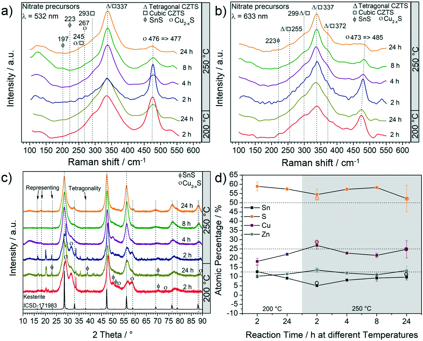 | ||
| Fig. 1 Characterization of particles obtained at different temperatures and for different time lengths. Raman analysis using (a) green and (b) red lasers; (c) XRD patterns and (d) EDX analysis: solid square data points represent SEM-EDX analysis and the empty circle data points represent TEM-EDX analysis. The products mainly consist of CZTS phase with Cu2−xS and SnS as the other main by-products. | ||
The second most intense peak that can be observed in all the Raman spectra is at around 474 cm−1 showing the presence of Cu2−xS.34 As the reaction time and/or the temperature are increased, a decrease in the intensity of this peak is observed. At 250 °C, an increase of time leads to a red-shift of the Cu2−xS peak. The shift is more evident under 633 nm laser (473 cm−1 → 485 cm−1) and has been assigned to an interconversion between different Cu2−xS phases. For example, the conversion of anilite, a low-temperature metastable phase, to covellite (stable phase) has already been reported.37 The monoclinic djurleite (P21/n) Cu1.94S is only weakly Raman active and therefore the intense Raman peak at 476 cm−1 and 473 cm−1 cannot be attributed to this phase. This is also supported by the XRD patterns (shown in Fig. 1c), where no reflections from Cu1.94S were detected. Such products, including Cu1.81S, are often observed in CZTS synthesis and have been thoroughly discussed in one of our previous studies.20 It should be noted that an exact identification of the Cu2−xS phase is fundamentally difficult with regard to the complexity of Cu2−xS, especially in nanoparticulate form.37 Ternary by-products were not observed by Raman spectroscopy. However, at a temperature as low as 200 °C the peak around 337 cm−1 is very broad; therefore the presence of SnS2, Cu2SnS3 and Cu3SnS4 having their most intense peaks at 315 cm−1, 303 cm−1 - 356 cm−1 and 318 cm−1, respectively, cannot be excluded. Moreover, at shorter reaction times, SnS can also be observed at 200 °C and 250 °C (Fig. 1a and b). As the temperature and reaction time increase, the formation of CZTS is clearly favoured. XRD and elemental analyses were performed to confirm the findings of Raman spectroscopy. Fig. 1c shows a set of XRD patterns for all the products and a reference kesterite (ICSD-171983 – tetragonal CZTS) pattern.
It can be observed that all three most intense reflections for CZTS at about 28.4°, 47.3° and 56.1° are present in all patterns. The samples synthesized at 200 °C have broad reflections and present additional low-intensity signals, especially at low 2θ°. These reflections are also observed in the pattern of samples synthesized at 250 °C for 2 h, whereas they disappear when the reaction time is increased. The exact assignment of the corresponding phases was not possible by XRD and Raman analyses, which instead show that Cu2−xS is the main by-product, followed by SnS. By increasing the reaction temperature to 250 °C and the reaction time to more than 2 h, the pattern comes closer to the standard of kesterite (ICSD-171983); however, a small amount of by-products, mainly Cu2−xS and SnS (reflections between 47° and 56°), are still observed, even for a reaction time of 24 h at 250 °C, in agreement with Raman analysis. Moreover, it is interesting to note that only the product after 24 h at 250 °C shows the reflections (marked with arrows in Fig. 1c) that differentiate the cubic CZTS from the tetragonal CZTS phase.8 Elemental analysis (Fig. 1d) shows that Zn was in near-stoichiometric concentrations, i.e. ∼12.5%, while a slight change in Cu concentration is observed based on reaction temperature, i.e. at 200 °C a Cu-deficient product is found (20%) and as the temperature is increased to 250 °C a near ideal concentration (25%) is observed. It should be noted that the heat of formation of binary tin sulphides is higher than that of the ternary and quaternary compounds, i.e. CTSs and CZTS.20 Furthermore, zinc does not form any ternary phase with sulphur and copper or tin, and in general the formation of CTS ternary phases has not been observed in this study. Therefore, at 250 °C the increase in Sn content with time hints towards active participation of Sn to form CZTS from binary compounds, which is the thermodynamically favoured product under these experimental conditions. Finally, the sulphur content was found to be higher than the expected 50%. Fig. 2 shows the (S)TEM analysis of the nanoparticles synthesized at 250 °C for 2 h and 24 h. The particles show a clear faceted shape. In the sample synthesized for 2 h, a broad size distribution can be identified, encompassing smaller particles of around 3–5 nm diameter, and larger particles with diameter of around 15–20 nm. The size of the particles in the sample synthesized at 250 °C for 24 h focuses on a mean value of around 8 nm. A detailed particle size distribution (PSD) for both samples is shown in the insets in Fig. 2a and d.
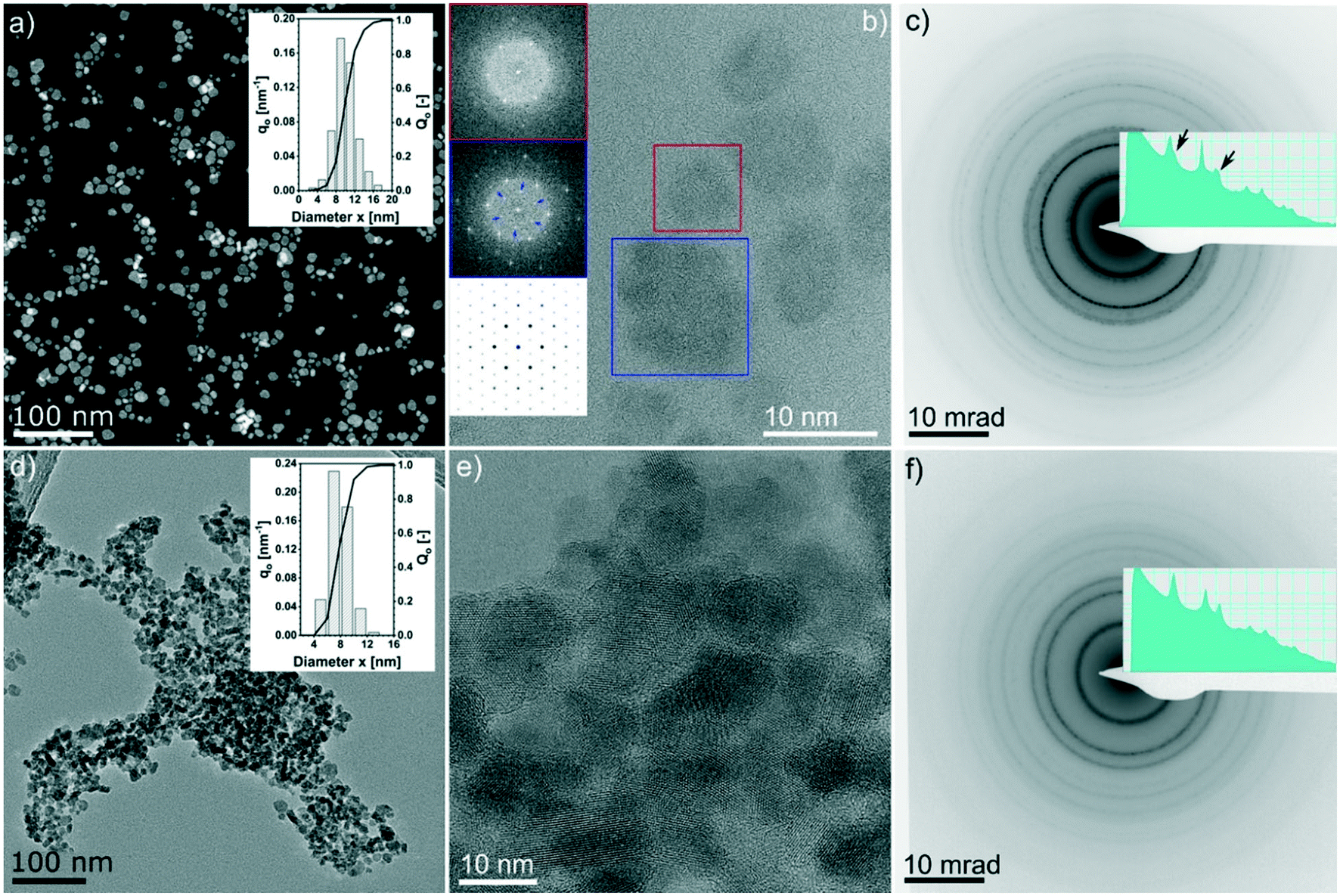 | ||
| Fig. 2 (S)TEM analysis of the nanoparticles synthesized under solvothermal conditions: (a–c) 2 h at 250 °C; (d–f) 24 h at 250 °C. Overview of the particle sizes with STEM Z-contrast (a) and bright field TEM (d); the insets in (a) and (d) are histograms of the corresponding particle size distribution. (b and e) Aberration corrected HRTEM images. (c and f) Selected area electron diffraction (log scale and contrast inverted for better visualization of the weak rings). Insets in (b) from top: fast Fourier transform (FFT) of the red and blue box marked regions and calculated [0001] diffraction pattern of CuS (ICSD 41911).The extra weak spots in the FFT of larger particles suggest the presence of the CuS phase. Insets in (c) and (f) are the radial integrated intensity profiles of the diffraction patterns (also shown in log scale). | ||
Fig. 2b shows the HRTEM lattice image of a few big and small particles after 2 h at 250 °C. The Fourier-transformed (FT) image from the colour marked regions are shown in the inset. The six-fold symmetry FT pattern confirms the particles are viewed along the closed packing {111}/{0001} planes, thus making it feasible to compare with simulations. FT of the bigger particles shows weak superlattice spots (blue inset in Fig. 2b), which are missing in the FT of the small particle (red inset in Fig. 2b) but do exist in the simulated diffraction pattern of the CuS phase (ICSD 41911, i.e., covellite phase, cf. the insets in Fig. 2b).
This evidence supports the theory that the larger particles are at least partially composed of CuS. Furthermore, we noticed evidence of a few occasions that bigger particles are composed of smaller nano-crystallites which are oriented differently, while planar faults or twin variants can be excluded in these cases (see an example in the ESI,† Fig. S2 and S3). This indicates that the bigger particles might be assembled by smaller particles. Fig. 2c and f show the SAED patterns of the 2 h and 24 h samples, respectively. Both patterns are consistent with the results of the XRD analysis (i.e., Fig. 1c, blue and orange profiles) whereby for the 2 h sample, the intense innermost ring is broadened and the third ring has a broad satellite ring at slightly higher diffraction angles, which is most likely due to the presence of the Cu2−xS by-product. Moreover, in the 24 h sample, those features completely disappeared.
A similar reactivity is observed also for the sample synthesized at a lower temperature and short reaction time. In particular, the EDX mapping and sum signal analysis on the sample synthesized at 200 °C for 2 h reveal an enrichment of Sn on the particles' surface (Fig. 3). In summary, the CZTS phase is already present in the sample synthesized at the lower temperature (200 °C) and the shortest time (2 h) investigated in this work, in equilibrium with relevant amounts of binary sulphides as secondary phases, whereas ternary phases were not observed throughout the time length and temperature of the work. Cu2−xS and a tin-rich phase were identified inside and on the surface of growing particles, respectively, hinting at a binary sulphide particle mediated growth mechanism.
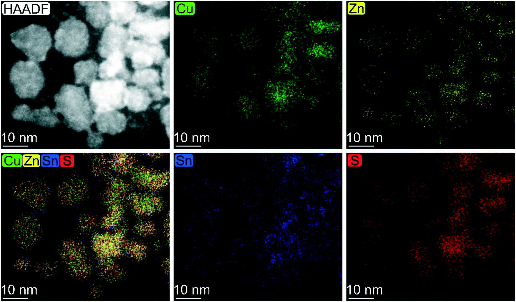 | ||
| Fig. 3 Elemental map based on EDX analysis carried out on CZTS particles synthesized under solvothermal conditions at 200 °C for 2 h. | ||
3.1 Reactivity of oleylamine and CS2 in anisole
Under the experimental conditions in the current work, carbon disulphide (CS2) is used as a sulphur precursor in combination with the ligand oleylamine (OLA). More specifically, the sulphur precursor CS2 is used in molar excess with respect to OLA, with the CS2/OLA molar ratio of ∼1.5 mol/mol (see the Experimental details section). Due to the nucleophilic character of OLA and the electrophilic character of CS2 at the carbon atom, the following reaction takes place, leading to the formation of a dithiocarbamate (DTC) molecule: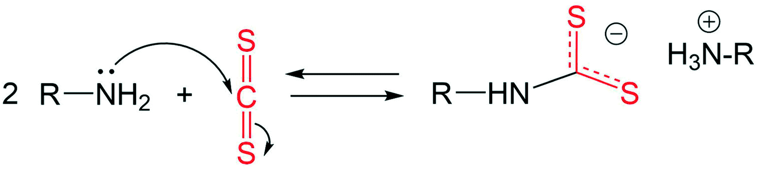 | (1) |
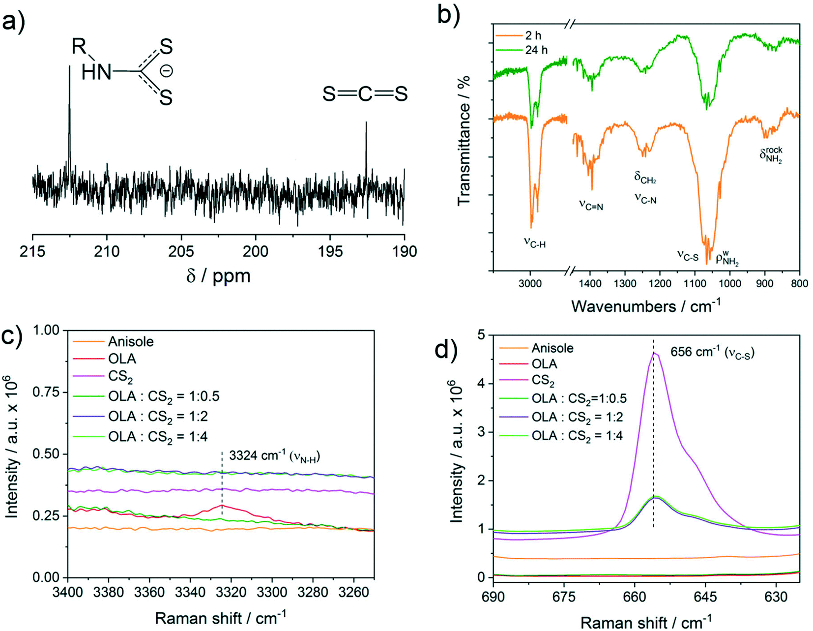 | ||
| Fig. 4 (a) Low-field 13C NMR spectrum of a solution of CS2 (0.2 M) and oleylamine (0.129 M) in anisole. (b) FTIR of the particles synthesized at 250 °C. (c and d) Raman spectra in solution of pure anisole (5 mL), OLA (1 mL, 3 mmol in 5 mL anisole), and CS2 (800 μL, 13 mmol in 5 mL anisole) and of anisole solutions of OLA (always 1 mL in 5 mL anisole) and various volumes of CS2: 90 μL, (1.49 mmol), 360 μL (5.96 mmol), and 800 μL (13 mmol) corresponding to OLA:CS2 ratio of 1:0.5, 1:2 and 1:4 mol:mol, respectively. | ||
To shed further light on the reaction between OLA and CS2 described by eqn (1), a Raman study was performed in solution using different molar ratios of OLA and CS2. In particular, an OLA:CS2 molar ratio of 1:0.5, 1:2 and 1:4 corresponding to the stoichiometric ratio and to a progressively larger excess of CS2 with respect to OLA was investigated (Fig. 4c and d). The spectra are compared with reference Raman spectra of OLA and CS2 in anisole with comparable concentrations (Fig. 4c and d). The results show that for the stoichiometric ratio of OLA:CS2 1:0.5 mol:mol, both the νN–H and νC![[double bond, length as m-dash]](https://www.rsc.org/images/entities/char_e001.gif) S disappear, whereas in the presence of an excess of CS2, a clear νCS vibration due to free CS2 at 656 cm−1 becomes evident (Fig. 4d). The use of an excess of CS2 as the sulphur source resembles the experimental conditions employed in the current work for the synthesis of CZTS nanoparticles. It is interesting to note that although the added volume of CS2 is the same (800 μL) in the pink and bright green spectra, the intensity of the CS2 peak at 656 cm−1 is remarkably reduced in the presence of OLA, indicating that part of the added CS2 is involved in the equilibrium described in eqn (1). No additional vibration modes that could be assigned specifically to the dithiocarbamate moiety were detected by Raman spectroscopy.
S disappear, whereas in the presence of an excess of CS2, a clear νCS vibration due to free CS2 at 656 cm−1 becomes evident (Fig. 4d). The use of an excess of CS2 as the sulphur source resembles the experimental conditions employed in the current work for the synthesis of CZTS nanoparticles. It is interesting to note that although the added volume of CS2 is the same (800 μL) in the pink and bright green spectra, the intensity of the CS2 peak at 656 cm−1 is remarkably reduced in the presence of OLA, indicating that part of the added CS2 is involved in the equilibrium described in eqn (1). No additional vibration modes that could be assigned specifically to the dithiocarbamate moiety were detected by Raman spectroscopy.
3.2 Surface characterization by XPS
First, XPS analysis was applied to further confirm the oxidation state of the elements in the samples synthesized at 250 °C as a function of reaction time. The results are shown in Fig. 5 and 6, where the spectra acquired over the energy range typical for the main XPS lines for Zn, Cu, Sn, N and S are shown, together with those acquired on the oxygen region. The Zn 2p, Cu 2p and Sn 3d profiles (Fig. 5) do not show relevant changes with reaction time; the positions of the main peaks, respectively at (1021.5 ± 0.2) eV, (931.9 ± 0.2) eV and (486.3 ± 0.2) eV, are consistent with the Zn(II), Cu(I) and Sn(IV) oxidation states, characteristic of the kesterite phase.40 The presence of Sn(II) species could not be fully excluded due to the small core level chemical shifts between the XPS signals of the two oxidation states of tin.41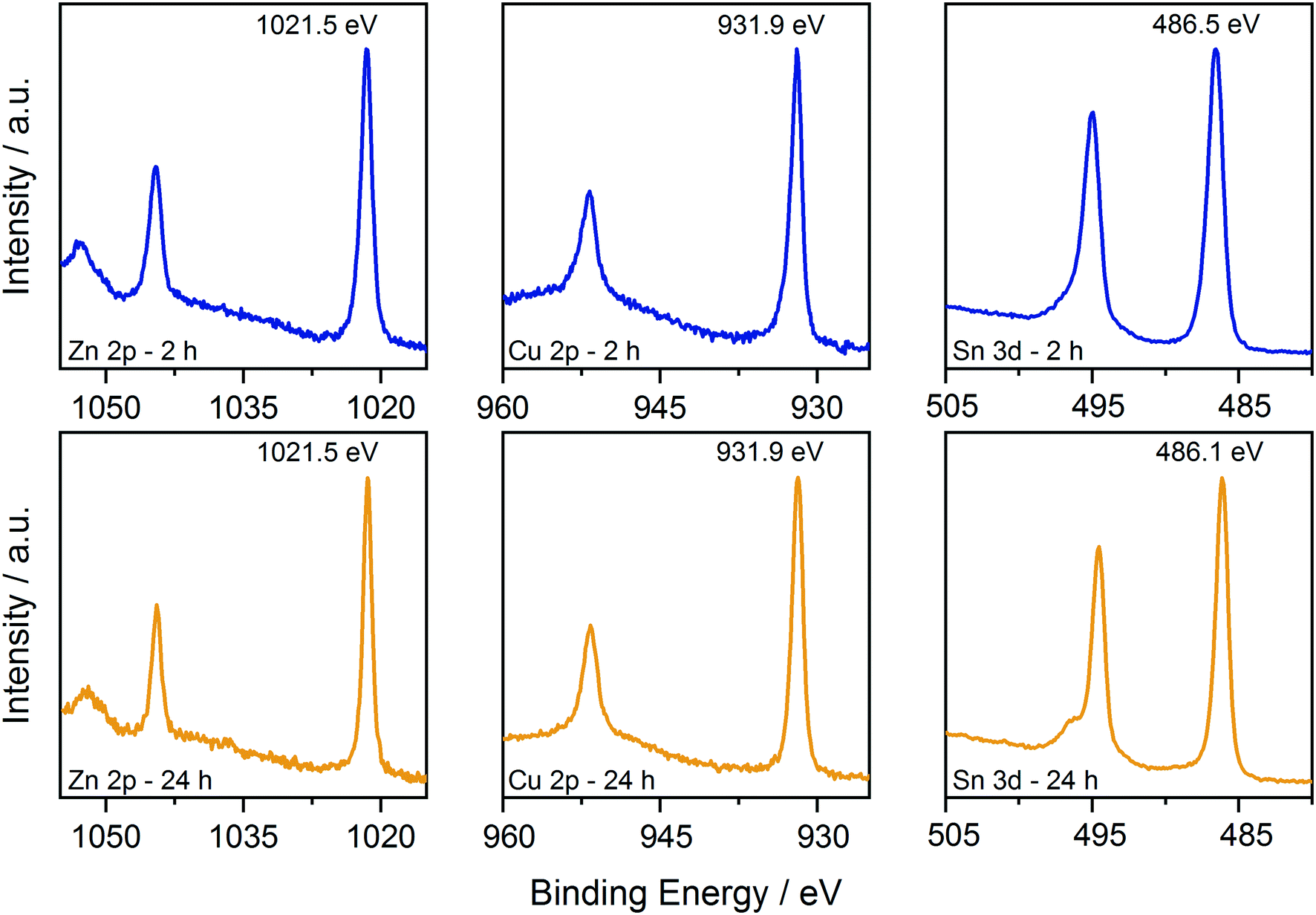 | ||
| Fig. 5 Comparison of the XPS data collected on the CZTS nanoparticles synthesized at 250 °C for 2 h and 24 h. Data are shown over the energy ranges typical for the main Zn, Cu, and Sn levels. | ||
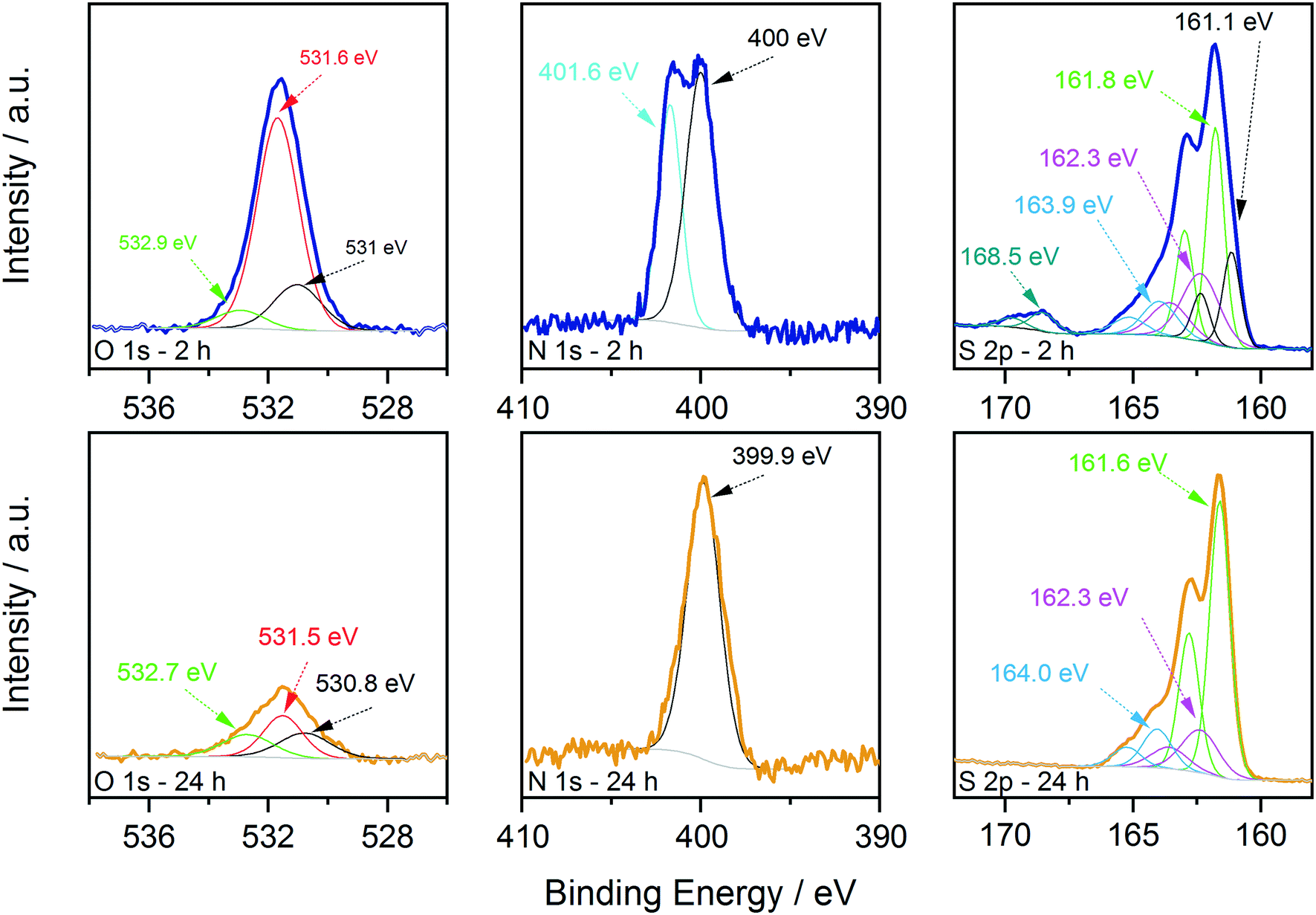 | ||
| Fig. 6 Comparison of the XPS data collected on the CTZS nanoparticles synthesized at 250 °C for 2 h (blue lines, top) and 24 h (gold lines, bottom). Data are shown over the energy ranges typical for the main O, N, and S levels, together with the results of the decomposition process. | ||
On the other hand, oxygen, nitrogen, and sulphur signals do show significant changes with reaction time (Fig. 6). In particular, the N 1s spectrum collected on the 2 hour sample clearly shows the presence of two distinct contributions, one centred at (400.0 ± 0.2) eV and one at (401.6 ± 0.2) eV, that could be attributed respectively to neutral amine nitrogen and charged N species, similarly to what we observed recently for CZTS nanoparticles synthesized using acetates as precursors.18 The high binding energy component is almost absent in the 24 hour sample, where the nitrogen signal is dominated by neutral amine species. Importantly, in both samples there is no trace of nitrates that should contribute to the N 1s spectrum with signals at a binding energy of approximately 407 eV.42 Therefore, the coordination of nitrates onto the surface of particles is not observed and can be excluded. The interpretation of the S 2p data required a more detailed analysis; fitting is obtained, imposing that each S state in the S 2p spectrum is represented by a pair of peaks (i.e. a doublet) having the same full width at half maximum, the standard spin–orbit splitting of 1.2 eV, and a branching ratio of 1/2. The position of each S 2p doublet is identified by the position of the 2p3/2 component (i.e. the component at lower binding energy and showing the higher intensity). For the 2 hour sample, five distinct doublets were needed to describe the observed experimental trend (Fig. 6). The main S contribution is represented by the doublet at (161.8 ± 0.2) eV (green lines), assigned to sulphides in CZTS, in agreement with our previous results and literature reports.18,40 At slightly lower binding energy, at (161.1 ± 0.2) eV (black lines), the presence of another doublet indicates that the sample also contains other sulphide species (Fig. 6). In particular, the same position has been reported in the literature for SnS species,43 and similar values have been measured on copper sulphides in the covellite phase (CuS),44 in agreement with the results of the HRTEM analysis. On the high binding energy side of the main doublet, two lower-intensity S species were added, having S 2p3/2 components at (162.3 ± 0.2) eV (magenta profiles) and (163.9 ± 0.2) eV (light blue profiles). In agreement with what we recently reported,18 these species could be attributed to bound dithiocarbamate moieties and unreacted CS2 precursor coordinated onto the surface of the obtained nanoparticles, respectively, as reported in the previous paragraph. As mentioned previously, a fifth S doublet was needed to obtain the best fit, characterized by an S 2p3/2 component at (168.5 ± 0.2) eV and assigned to oxidized S6+ species (likely in the sulphate form).42 Increasing the reaction time to 24 hours induced the disappearance of the sulphate species as well as of the lower binding energy sulphide doublet, while the other three S signals remained with similar positions and relative intensities to the sample synthesized for a shorter reaction time.
These results are in agreement with the Raman, XRD (Fig. 1) and TEM results (Fig. 2) and indicate that the binary sulphides are present in the early stages of particle formation and tend to disappear over time. The presence of the charged nitrogen and sulphate component indicates that the sample synthesized after 2 h at 250 °C undergoes surface oxidation. The disappearance of these signals has been interpreted in light of the electron microscopy evidence that longer time at 250 °C results in larger particles, i.e. in smaller total surface area and hence, in reduced tendency to undergo oxidation. This explanation is also supported by the XPS results of the content of surface oxygen species that varied with reaction time. Fig. 6 shows the comparison of the O 1s signals in the two cases. The content of oxygen species decreased with the increase of reaction time. As a reference, the O/Sn molar ratio changed from 1.3 to 0.4 when moving from 2 to 24 hours of reaction. EDX measurement in the TEM also show similar results of higher O signal in the 2 h sample (see the ESI,† Fig. S4). In both cases, the data could be fitted with 3 components, centred at (530.9 ± 0.2) eV, (531.6 ± 0.2) eV and (532.8 ± 0.2) eV, named in the following as O1, O2 and O3, respectively. The O1 component could be assigned to metal oxides. In fact, SnO2 is reported in the 530.6–531 eV range, Cu2O at 530.7 eV and ZnO at 530.7 eV.42 The O2 component could instead be assigned to either absorbed C–OH species and metal hydroxides,40 but considering the outcome of the analysis of the S 2p signals, it is most likely due to sulphates.45 The O3 component is instead due to adsorbed water.40 The formation of these species is not surprising, considering that hydrated salts are used as molecular precursors for the synthesis of CZTS particles (see Experimental details). Interestingly, while the intensity of the adsorbed water component seems to be stable with reaction time, the intensity (and therefore the amount) of the metal oxides and sulphates/hydroxides clearly decreased with time (especially in the sulphate case, in nice agreement with that observed in the S 2p region), indicating that these by-products could be removed/reduced by carefully controlling the reaction conditions.
4. Discussion
The DTC molecules formed according to eqn (1) are coordinating species, therefore they form complexes in solution with the metal precursors and are found coordinated onto the particle surface at the end of the synthesis (Fig. 1d, 4b and 6).18 The DTC–metal complexes can also form by insertion of CS2 in the metal–nitrogen bond, as previously reported for Sn–N bonds.46 Metal salts are mainly present as nitrates, which are weakly coordinating anions; therefore, the Cu and Zn OLA–DTC complexes are expected to be very reactive under the experimental conditions employed in the current work. For instance, the Cu–OLA–DTC complex forms, at the early stages of particle formation, the corresponding Cu2−xS binary sulphides besides being incorporated in the CZTS particles (Fig. 1). On the other hand, Sn(II) and Sn(IV) acetate also form the corresponding binary sulphides under analogous experimental conditions (Fig. 1 and 5).18 Therefore, the following equation can be written to account for the reactivity observed in our study (eqn (2)):| CuX2 + ZnX2 + “SnAc2 or SnAc4” + “excess S” ⇔ Cu2−xS↓ + ZnS↓ + SnS/SnS2↓ | (2) |
Concerning the formation mechanism of the quaternary phase, CZTS nanoparticles were already observed as a product after the short reaction time (2 h) at 200 °C together with a large amount of binary sulphides like Cu2−xS and SnS, whereas the formation of ternary sulphide phases was not observed throughout the work. By increasing the synthesis temperature and the reaction time, the amount of binary phases was remarkably reduced; CZTS becomes the main product and was observed to undergo a cubic → tetragonal transformation.
The following equations describe the processes that can lead to the formation of CZTS nanoparticles in the liquid phase:
| CuX2 + ZnX2 + “SnAc2 or SnAc4” + “excess S” ⇔ Cu2ZnSnS4↓ | (3) |
| Cu2−xS + ZnS + SnS/SnS2 ⇔ Cu2ZnSnS4↓ | (4) |
Eqn (3) describes the formation of the CZTS phase via a nucleation and growth process involving the direct transformation of molecular precursors, whereas eqn (4) describes the formation of the quaternary phase through the transformation of binary sulphides.
The results of the current study clearly show that the CZTS phase forms at the expense of the binary sulphide species and that this transformation is a slow process, requiring several hours at high temperature to be completed (Fig. 1). On the other hand, the slow rate of the process described in eqn (4) and observed in our study cannot be due to the adsorption of nitrate ions on the surface of intermediate binary sulphides, as demonstrated by XPS analysis (Fig. 5 and 6). This is in contrast with our previous findings that the adsorption of chlorides on the surface of ZnS nanoparticles is hindering the formation of the quaternary phase when chlorides are used as starting salts.18 Instead, the particle surface is occupied by OLA and OLA–DTC moieties as shown in Fig. 4b, accounting for the deviation from stoichiometry observed for sulphur (Fig. 1d and 6). This is analogous to that reported when acetate and chloride salts were used as synthesis precursors, with the organic side reaction being a common element between these different synthetic routes.18 The XPS analysis also supports remarkable changes of the particle surface over time, in particular regarding the oxygen content, indicating that the particles undergo a surface reorganization over time. These data, taken together with the evidence of TEM analysis in Fig. 2b about the inclusions of CuS inside the larger particles, and the EDX maps reported in Fig. 3 showing an excess of tin on the particles' surface, suggest the occurrence of surface and internal recrystallization processes over time that does not exclude a particle-mediated growth mechanism.
However, with the results of the current study, it is not possible to assess whether the minority CZTS products isolated after 2 h of reaction time, both at 200 and 250 °C, form according to eqn (3), i.e. through a direct nucleation and growth of the CZTS phase, or rather via a binary sulphide-mediated growth, described by eqn (4). In fact, the formation of CZTS nanocrystals from molecular precursors (eqn (3)) would be a very fast process in comparison with the formation of CZTS from binary phases (eqn (4)). We believe that this open question remains and could be better answered by an in situ study focused on the early stages of particle formation during the heating ramps (Fig. S1, ESI†).
Conclusion
The formation of CZTS nanoparticles under solvothermal conditions was investigated using anisole as the solvent, oleylamine as the organic ligand and CS2 as the sulphur source. The inorganic salt precursors, containing mainly nitrate as a counterion, promote the formation of binary sulphides such as Cu2−xS, CuS and SnS as the main reaction products at low temperature (200 °C) and short reaction time (2 h), together with small amounts of CZTS particles. By increasing the temperature and/or the reaction time, the concentration of binary sulphides decreases and CZTS becomes the main reaction product. Under the experimental conditions employed in the current paper, the formation of ternary sulphides was not observed, supporting a prompt reactivity of the Zn(II) molecular precursor containing the nitrate counterion. Moreover, the longer reaction times also facilitate the transition from cubic to tetragonal CZTS. 13C NMR and Raman spectroscopy in solution and FTIR spectroscopy on the powder samples together with XPS analysis showed that the excess of sulphur on the particle surface was due to the adsorption of a dithiocarbammate (DTC) molecule that forms in situ upon reaction of the organic ligand oleylamine and the sulphur precursor CS2. Therefore, when the metal starting precursors are present mostly as nitrate salts, CZTS nanoparticles form predominantly by a slow transformation of binary sulphides into quaternary phases via an internal re-crystallization mechanism. However, the direct formation of small amounts of CZTS nanoparticles by a direct nucleation and growth mechanism cannot be excluded and requires a closer look at the products before 2 h of reaction time.Conflicts of interest
There are no conflicts to declare.Acknowledgements
This work was supported within the framework of the German Excellence Initiative by the Deutsche Forschungsgemeinschaft through the Cluster of Excellence “Engineering of Advanced Materials” at the Friedrich-Alexander-University of Erlangen-Nuremberg.References
- (a) T. K. Todorov, K. B. Reuter and D. B. Mitzi, Adv. Mater., 2010, 22, E156–E159 Search PubMed; (b) S. Giraldo, Z. Jehl, M. Placidi, V. Izquierdo-Roca, A. Pérez-Rodríguez and E. Saucedo, Adv. Mater., 2019, 31, e1806692 Search PubMed.
- E. Ha, L. Y. S. Lee, J. Wang, F. Li, K.-Y. Wong and S. C. E. Tsang, Adv. Mater., 2014, 26, 3496–3500 Search PubMed.
- W. Yang, Y. Oh, J. Kim, M. J. Jeong, J. H. Park and J. Moon, ACS Energy Lett., 2016, 1, 1127–1136 Search PubMed.
- R. V. Digraskar, V. S. Sapner, S. M. Mali, S. S. Narwade, A. V. Ghule and B. R. Sathe, ACS Omega, 2019, 4, 7650–7657 Search PubMed.
- T. Tang, X. Xu, Z. Wang, J. Tian, Y. Yang, C. Ou, H. Bao and T. Liu, Chem. Commun., 2019, 55, 13148–13151 Search PubMed.
- K. Wei and G. S. Nolas, ACS Appl. Mater. Interfaces, 2015, 7, 9752–9757 Search PubMed.
- EU, Communication from the Commission to the European Parliament, the Council, the European Economic and Social Committee and the Committee of the Regions on the 2017 list of Critical Raw Materials for the EU, available at: http://eur-lex.europa.eu/legal-content/EN/ALL/?uri=COM:2017:0490:FIN, (accessed: 2017).
- M. Brandl, R. Ahmad, M. Distaso, H. Azimi, Y. Hou, W. Peukert, C. J. Brabec and R. Hock, Thin Solid Films, 2015, 582, 269–271 Search PubMed.
- M. Kumar, A. Dubey, N. Adhikari, S. Venkatesan and Q. Qiao, Energy Environ. Sci., 2015, 8, 3134–3159 Search PubMed.
- C. J. Bosson, M. T. Birch, D. P. Halliday, K. S. Knight, A. S. Gibbs and P. D. Hatton, J. Mater. Chem. A, 2017, 5, 16672–16680 Search PubMed.
- M. Dimitrievska, A. Fairbrother, R. Gunder, G. Gurieva, H. Xie, E. Saucedo, A. Pérez-Rodríguez, V. Izquierdo-Roca and S. Schorr, Phys. Chem. Chem. Phys., 2016, 18, 8692–8700 Search PubMed.
- K. Kim, I. Kim, Y. Oh, D. Lee, K. Woo, S. Jeong and J. Moon, Green Chem., 2014, 16, 4323–4332 Search PubMed.
- V. T. Tiong, Y. Zhang, J. Bell and H. Wang, CrystEngComm, 2014, 16, 4306–4313 Search PubMed.
- A. Singh, H. Geaney, F. Laffir and K. M. Ryan, J. Am. Chem. Soc., 2012, 134, 2910–2913 Search PubMed.
- Q. Luo, Y. Zeng, L. Chen and C. Ma, Chem. – Asian J., 2014, 9, 2309–2316 Search PubMed.
- S. Singh, P. Liu, A. Singh, C. Coughlan, J. Wang, M. Lusi and K. M. Ryan, Chem. Mater., 2015, 27, 4742–4748 Search PubMed.
- R. Ahmad, K. S. Nicholson, Q. Nawaz, W. Peukert and M. Distaso, J. Nanopart. Res., 2017, 19, 1 Search PubMed.
- R. Ahmad, N.-U.-H. Saddiqi, M. Wu, M. Prato, E. Spiecker, W. Peukert and M. Distaso, Inorg. Chem., 2020, 59, 1973–1984 Search PubMed.
- C. B. Murray, C. R. Kagan and M. G. Bawendi, Annu. Rev. Mater. Sci., 2000, 30, 545–610 Search PubMed.
- R. Ahmad, M. Brandl, M. Distaso, P. Herre, E. Spiecker, R. Hock and W. Peukert, CrystEngComm, 2015, 17, 6972–6984 Search PubMed.
- S. Engberg, J. Symonowicz, J. Schou, S. Canulescu and K. M. Ø. Jensen, ACS Omega, 2020, 18, 10501–10509 Search PubMed.
- G. Barone, T. Chaplin, T. G. Hibbert, A. T. Kana, M. F. Mahon, K. C. Molloy, I. D. Worsley, I. P. Parkin and L. S. Price, J. Chem. Soc., Dalton Trans., 2002, 1085–1092 Search PubMed.
- G. Murtaza, S. Alderhami, Y. T. Alharbi, U. Zulfiqar, M. Hossin, A. M. Alanazi, L. Almanqur, E. U. Onche, S. P. Venkateswaran and D. J. Lewis, ACS Appl. Energy Mater., 2020, 3, 1952–1961 Search PubMed.
- M. Al-Shakban, P. D. Matthews, N. Savjani, X. L. Zhong, Y. Wang, M. Missous and P. O'Brien, J. Mater. Sci., 2017, 52, 12761–12771 Search PubMed.
- D. Fuhrmann, S. Dietrich and H. Krautscheid, Inorg. Chem., 2017, 56, 13123–13131 Search PubMed.
- D. Fuhrmann, S. Dietrich and H. Krautscheid, Chemistry, 2017, 23, 3338–3346 Search PubMed.
- A. S. R. Chesman, J. van Embden, N. W. Duffy, N. A. S. Webster and J. J. Jasieniak, Cryst. Growth Des., 2013, 13, 1712–1720 Search PubMed.
- Y. Cao, M. S. Denny, J. V. Caspar, W. E. Farneth, Q. Guo, A. S. Ionkin, L. K. Johnson, M. Lu, I. Malajovich, D. Radu, H. D. Rosenfeld, K. R. Choudhury and W. Wu, J. Am. Chem. Soc., 2012, 134, 15644–15647 Search PubMed.
- K.-J. Kim, C. Pan, S. Bansal, R. Malhotra, D.-H. Kim and C.-H. Chang, Sustainable Energy Fuels, 2017, 1, 267–274 Search PubMed.
- Z. Li, J. C. W. Ho, K. K. Lee, X. Zeng, T. Zhang, L. H. Wong and Y. M. Lam, RSC Adv., 2014, 4, 26888–26894 Search PubMed.
- H. Wang, A. Yasin, N. J. Quitoriano and G. P. Demopoulos, Nanomaterials, 2019, 9, 1382 Search PubMed.
- O. Awadallah and Z. Cheng, IEEE J. Photovolt., 2016, 6, 764–769 Search PubMed.
- Y. M. Eggeler, D. Kubacka, P. Pichler, M. Wu and E. Spiecker, Scr. Mater., 2021, 192, 120–124 Search PubMed.
- A.-J. Cheng, M. Manno, A. Khare, C. Leighton, S. A. Campbell and E. S. Aydil, J. Vac. Sci. Technol., A, 2011, 29, 51203 Search PubMed.
- M. Dimitrievska, H. Xie, A. Fairbrother, X. Fontané, G. Gurieva, E. Saucedo, A. Pérez-Rodríguez, S. Schorr and V. Izquierdo-Roca, Appl. Phys. Lett., 2014, 105, 31913 Search PubMed.
- X. Fontané, V. Izquierdo-Roca, E. Saucedo, S. Schorr, V. O. Yukhymchuk, M. Y. Valakh, A. Pérez-Rodríguez and J. R. Morante, J. Alloys Compd., 2012, 539, 190–194 Search PubMed.
- J. A. Schmidt, A. E. Sagua and G. Lescano, J. Chem. Thermodyn., 1998, 30, 283–290 Search PubMed.
- H. L. M. van Gaal, J. W. Diesveld, F. W. Pijpers and J. G. M. van der Linden, Inorg. Chem., 1979, 18, 3251–3260 Search PubMed.
- A. W. Wills, M. S. Kang, A. Khare, W. L. Gladfelter and D. J. Norris, ACS Nano, 2010, 4, 4523–4530 Search PubMed.
- J. Ge and Y. Yan, iScience, 2018, 1, 55–71 Search PubMed.
- L. Kövér, G. Moretti, Z. Kovács, R. Sanjinés, I. Cserny, G. Margaritondo, J. Pálinkás and H. Adachi, J. Vac. Sci. Technol., A, 1995, 13, 1382–1388 Search PubMed.
- NIST X-ray Photoelectron Spectroscopy Database, Version 4.1, (National Institute of Standards and Technology, Gaithersburg, 2012), http://srdata.nist.gov/xps/ Search PubMed.
- R. B. Shalvoy, G. B. Fisher and P. J. Stiles, Phys. Rev. B, 1977, 15, 1680–1697 Search PubMed.
- Y. Xie, A. Riedinger, M. Prato, A. Casu, A. Genovese, P. Guardia, S. Sottini, C. Sangregorio, K. Miszta, S. Ghosh, T. Pellegrino and L. Manna, J. Am. Chem. Soc., 2013, 135, 17630–17637 Search PubMed.
- M. Wahlqvist and A. Shchukarev, J. Electron Spectrosc. Relat. Phenom., 2007, 156-158, 310–314 Search PubMed.
- C. A. Stewart, D. A. Dickie, Y. Tang and R. A. Kemp, Inorg. Chim. Acta, 2011, 376, 73–79 Search PubMed.
Footnote |
| † Electronic supplementary information (ESI) available. See DOI: 10.1039/d0ce01566k |
| This journal is © The Royal Society of Chemistry 2021 |