
Experimental and computational evidence for a stabilising C–Cl(lone-pair)⋯π(chelate-ring) interaction†
Sang Loon
Tan
a,
See Mun
Lee
 a,
Kong Mun
Lo
a,
A.
Otero-de-la-Roza
*b and
Edward R. T.
Tiekink
*a
a,
Kong Mun
Lo
a,
A.
Otero-de-la-Roza
*b and
Edward R. T.
Tiekink
*a
aResearch Centre for Crystalline Materials, School of Science and Technology, Sunway University, 47500 Bandar Sunway, Selangor Darul Ehsan, Malaysia. E-mail: edwardt@sunway.edu.my
bDepartamento de Química Física y Analítica, Facultad de Química, Universidad de Oviedo, 33006 Oviedo, Spain. E-mail: alberto@carbono.quimica.uniovi.es
First published on 2nd November 2020
Abstract
In addition to a variety of conventional non-covalent intermolecular interactions such as C–H⋯π (arene), C–H⋯Cl and π(arene)⋯π(chelate-ring) contacts, the molecular packing in the crystal of an organotin dithiocarbamate compound, [SnCl(4-ClC6H4)2{S2CN(i-Pr)2}], exhibits evidence for a C–Cl⋯π(chelate-ring) interaction. These interactions occur via a side-on approach of the chloride atom to the chelate-ring and therefore are characterised as C–Cl(lone-pair)⋯π(chelate-ring) interactions, are shown to be attractive by NCI plots and QTAIM analysis, and are apparent in the calculated Hirshfeld surfaces. Theory suggests the energy of association provided by the C–Cl⋯π(chelate-ring) interactions to be about 3–4 kcal mol−1, a value greater than for analogous C–Cl⋯π(arene) and C–H⋯π(arene) interactions. A survey of the literature for related structures suggests that these interactions are not common. The newly described C–Cl(lone-pair)⋯π(chelate-ring) interactions add to the variety of intermolecular interactions able to be formed by chelate-rings in the supramolecular chemistry of metal complexes.
Introduction
The important role π-systems play in supramolecular chemistry is well established1 with an important subset of these being anion⋯π interactions.2–6 Halide/halogen⋯π interactions feature prominently among such interactions which have the common feature of being counter-intuitive in that two ostensibly electron-rich species are in close proximity, a feature that therefore attracts the interest of theoreticians.7–9 The explanation for the attractive nature of these interactions between like-charged species largely rests with the σ-hole concept10–12 whereby an electron-deficient region about, for example, a halide atom of a C–X bond arises owing to an anisotropic distribution of electron-density about the X atom. Thus, about the X atom there is a build-up of electron-density in the region perpendicular to the C–X bond which is compensated by an electron-deficient region at the tip of the X atom and parallel to the C–X bond – it is this tip which interacts with the π-system.10–12 While long known in protein structures/medicinal chemistry,13,14 being first commented upon in a serine protease S1 pocket in the structure of a thrombin-inhibitor,15 perhaps the earliest crystallographic evidence for a Cl⋯π interaction in molecular chemistry was reported in a copper(II) complex featuring a functionalised triazine ligand.16 Since these early discoveries, halogen⋯π bonding interactions have continued to attract attention in terms of medicinal chemistry/molecular biology,17,18 functional materials19–21 and crystal engineering.22More recent investigations into the role of π-systems contributing to supramolecular aggregation in crystals has focused upon chelate-rings. Chelate-rings are known to exhibit metallo-aromatic behaviour23,24 and therefore it is perhaps not surprising they can also participate in analogous interactions akin to their organic counterparts. In fact, a full range of interactions, as for organic π-systems, are now well documented such as C–H⋯π(chelate-ring),25–27 π(chelate-ring)⋯π(arene)28–30 and π(chelate-ring)⋯π(chelate-ring).30–32 Rather than being intellectual curiosities, such interactions provide significant energies of stabilisation in the crystals in which they occur, indeed, often greater energies than the equivalent contacts involving organic π-systems.33 In the present report, a gap in knowledge is addressed whereby evidence for a chloride⋯π(chelate-ring) interaction is presented, that is, in the crystal of an organotin dithiocarbamate compound, [SnCl(4-ClC6H4)2{S2CN(i-Pr)2}] (1), which was originally investigated in the context of biological potential of organotin dithiocarbamates.34 To the best of our knowledge, the only possible precedent for an analogous interaction specifically discussed in the literature is a putative Br⋯π interaction where the π-system is defined by a 16-membered, {–CuOC5O}2 metallo-aromatic ring in a binuclear complex whereby the copper(II) atoms are bridged by two monodentate carboxylate groups of a bridging, substituted 1,3-dicarboxylate di-anion.35
Experimental
Chemicals and instrumentation
The melting point was determined on a Mel-temp II digital melting point apparatus. The IR spectrum was recorded in a KBr pellet on a Perkin-Elmer Spectrum RX1 FT-IR spectrophotometer. 1H and 13C{1H} NMR spectra were recorded in DMSO-d6 solution on a Bruker Ascend 400 MHz NMR spectrometer with chemical shifts reported relative to tetramethylsilane. UV-vis spectra were recorded in acetonitrile solution on a Shimadzu UV-3600 Plus spectrophotometer. Elemental analyses were carried out on a Perkin Elmer EA2400 CHNS elemental analyzer. The powder X-ray diffraction (PXRD) pattern was measured on a Rigaku Miniflex 600 X-ray diffractometer at 293 K using Cu Kα (λ = 1.5418 Å) radiation in the 2θ range 5 to 70°. The comparisons between experimental and calculated (from the CIF) PXRD patterns were performed with Rigaku's PDXL2 software (https://www.rigaku.com/en/products/software/pdxl/overview).Synthesis
Tetra(4-chlorophenyl)tin was synthesised from the reaction of stannic chloride (Fluka) with 4-chlorophenylmagnesium bromide (prepared from the Grignard reaction of magnesium (Merck) and 4-bromochlorobenzene (Fluka) in tetrahydrofuran) in a 1![[thin space (1/6-em)]](https://www.rsc.org/images/entities/char_2009.gif) :4 molar ratio.36 Subsequently, di(4-chlorophenyl)tin dichloride was synthesised from the comproportionation reaction of tetra(4-chlorophenyl)tin with stannic chloride (Fluka) in a 1:1 molar ratio to obtain a white precipitate. The sodium dithiocarbamate salt, Na[S2CN(i-Pr)2], was prepared in situ (methanol, 15 ml) from the reaction of CS2 (Merck; 0.25 mmol) with diisopropylamine (Merck, 0.25 mmol) and NaOH (0.02 ml; 50% w/v); CS2 was added dropwise into the methanolic solution. The resulting solution was kept at 273 K for 0.5 h. Di(4-chlorophenyl)tin dichloride (0.25 mmol, 0.10 g) in methanol (10 ml) was added to the dithiocarbamate salt (methanol, 10 ml). The resulting mixture was stirred under reflux for 2 h. The filtrate was evaporated slowly until a white precipitate was formed. The precipitate was recrystallised from its methanol–acetone (1:1, 5 ml) solution by slow evaporation to yield colourless crystals. Yield: 0.050 g (36.1%). M.pt: 467–468 K. Calcd for C19H22Cl3NS2Sn: C 41.22; H 4.00; N 2.53%. Found: C 40.89; H: 3.76, N: 2.14%. IR (cm−1) 1470 (s) ν(C–N); 1338 (m) ν(C–N); 1011 (s) ν(C–S); 578 (w) ν(Sn–S). 1H NMR (DMSO-d6, ppm): δ 1.25–1.42 (m, 12H, CH3), 4.54 (br, 2H, CH), 7.34–7.51 (m, 4H, Ph–H), 7.96–8.08 (m, 4H, Ph–H). 13C{1H} NMR (DMSO-d6, ppm): 19.6 (CH3), 46.9 (CH), 127.3, 127.7, 128.0, 129.0, 133.9, 134.5, 137.7, 138.6 (Ph–C), 193.4 (S2C). UV (acetonitrile; nm, L mol−1 cm−1): λabs = 232, ε = 36650; λabs = 196, ε = 84000.
:4 molar ratio.36 Subsequently, di(4-chlorophenyl)tin dichloride was synthesised from the comproportionation reaction of tetra(4-chlorophenyl)tin with stannic chloride (Fluka) in a 1:1 molar ratio to obtain a white precipitate. The sodium dithiocarbamate salt, Na[S2CN(i-Pr)2], was prepared in situ (methanol, 15 ml) from the reaction of CS2 (Merck; 0.25 mmol) with diisopropylamine (Merck, 0.25 mmol) and NaOH (0.02 ml; 50% w/v); CS2 was added dropwise into the methanolic solution. The resulting solution was kept at 273 K for 0.5 h. Di(4-chlorophenyl)tin dichloride (0.25 mmol, 0.10 g) in methanol (10 ml) was added to the dithiocarbamate salt (methanol, 10 ml). The resulting mixture was stirred under reflux for 2 h. The filtrate was evaporated slowly until a white precipitate was formed. The precipitate was recrystallised from its methanol–acetone (1:1, 5 ml) solution by slow evaporation to yield colourless crystals. Yield: 0.050 g (36.1%). M.pt: 467–468 K. Calcd for C19H22Cl3NS2Sn: C 41.22; H 4.00; N 2.53%. Found: C 40.89; H: 3.76, N: 2.14%. IR (cm−1) 1470 (s) ν(C–N); 1338 (m) ν(C–N); 1011 (s) ν(C–S); 578 (w) ν(Sn–S). 1H NMR (DMSO-d6, ppm): δ 1.25–1.42 (m, 12H, CH3), 4.54 (br, 2H, CH), 7.34–7.51 (m, 4H, Ph–H), 7.96–8.08 (m, 4H, Ph–H). 13C{1H} NMR (DMSO-d6, ppm): 19.6 (CH3), 46.9 (CH), 127.3, 127.7, 128.0, 129.0, 133.9, 134.5, 137.7, 138.6 (Ph–C), 193.4 (S2C). UV (acetonitrile; nm, L mol−1 cm−1): λabs = 232, ε = 36650; λabs = 196, ε = 84000.
X-ray crystallography
Intensity data for a colourless crystal of 1 (0.065 × 0.125 × 0.193 mm) were measured at 100, 150, 200, 250, 273 and 298 K on a Rigaku/Oxford Diffraction XtaLAB Synergy diffractometer (Dualflex, AtlasS2) fitted with CuKα radiation (λ = 1.54178 Å) so that θmax = 67.1°. Data processing and Gaussian absorption corrections were accomplished with CrysAlis Pro.37 The structure was solved by direct methods38 and the refinement was by full-matrix least squares on F2 with anisotropic displacement parameters for all non-hydrogen atoms.39 The C-bound hydrogen atoms were placed on stereochemical grounds and refined with fixed geometries. A weighting scheme of the form w = 1/[σ2(Fo2) + (0.037P)2 + 1.248P] where P = (Fo2 + 2Fc2)/3 was introduced in the refinement. The maximum and minimum residual density peaks of 0.39 and 1.62 e Å−3, respectively, were located 1.06 and 0.91 Å from the Cl3 and Sn atoms, respectively. The programs WinGX,40 ORTEP-3 for Windows,40 PLATON41 and DIAMOND42 were also used in the study.Crystal data for 1 at 100 K: C19H22Cl3NS2Sn, M = 553.53, monoclinic, P21/n, a = 10.12941(5) Å, b = 16.43674(9) Å, c = 13.38681(7) Å, β = 96.9574(5)°, V = 2212.42(2) Å3, Z = 4, Dx = 1.662 g cm−3, μ = 14.311 mm−1, no. reflections = 26819, no. unique reflections = 3946, no. reflections with I ≥ 2σ(I) = 3863, R (obs. data) = 0.022, Rw (all data) = 0.057. Data for all data collections are tabulated in ESI† Table S1.
Results and discussion
Compound 1, [SnCl(4-ClC6H4)2{S2CN(i-Pr)2}], was synthesised from the 1:1 metathetical reaction of (4-ClC6H4)2SnCl2 and Na[S2CN(i-Pr)2]. The expected spectroscopic responses were noted; see the Experimental section for data. Thus, in the solid-state IR spectrum, characteristic ν(C–N), ν(C–S) and ν(Sn–S) absorptions were evident and the solution NMR showed the expected resonances (1H and 13C{1H}) and integration (1H) with the 13C{1H} signal due to S2![[C with combining low line]](https://www.rsc.org/images/entities/char_0043_0332.gif) noted at 193.4 ppm. Two absorptions were noted in the UV spectrum, with the low- and high-energy absorptions assigned to π⋯π* transitions associated with the delocalised C–S bonds and the phenyl rings, respectively. A comparison of the experimental powder X-ray diffraction pattern with the simulated patterns calculated from the CIF indicates that the single crystal result is representative of the bulk materials and indicates the absence of a phase change, see ESI† Fig. S1.
noted at 193.4 ppm. Two absorptions were noted in the UV spectrum, with the low- and high-energy absorptions assigned to π⋯π* transitions associated with the delocalised C–S bonds and the phenyl rings, respectively. A comparison of the experimental powder X-ray diffraction pattern with the simulated patterns calculated from the CIF indicates that the single crystal result is representative of the bulk materials and indicates the absence of a phase change, see ESI† Fig. S1.
Molecular structure
The molecular structure of 1, determined at 100 K, is shown in Fig. 1. The tin atom is penta-coordinated within a C2ClS2 donor set defined by the ipso-C atoms of the 4-chlorophenyl substituents, a chloride and two dithiocarbamate-sulphur atoms. The dithiocarbamate ligand is asymmetrically chelating, binding the tin centre with disparate Sn–S bond lengths [Sn–S1 = 2.4596(5) Å and Sn–S2 = 2.6354(5) Å]. The disparity in the Sn–S bond lengths results in a significant difference in the associated C–S bond lengths with that involved the more tightly bound S1 atom [C1–S1 = 1.755(2) Å] being longer than that involving the less tightly bound S2 atom [C1–S2 = 1.722(2) Å]. The C1–N1 bond length [1.320(3) Å] is significantly shorter than the N1–C2 [1.500(3) Å] and N1–C5 [1.498(3) Å] bonds which is consistent with a significant contribution of the dithiolate canonical form, i.e.(2−)S2C![[double bond, length as m-dash]](https://www.rsc.org/images/entities/char_e001.gif) N(+)(i-Pr)2, to the overall electronic structure of the dithiocarbamate anion.27 One of the contributing reasons for the disparity in the Sn–S bonds rests with the observation that the S2 atom is approximately trans to the electronegative chlorido substituent [Cl1–Sn–S2 = 157.850(18)°]. The range of angles about the tin atom is relatively large, that is 157.846(17)° for the aforementioned Cl1–Sn–S2 angle to an acute 70.418(16)° for the S1–Sn–S2 chelate angle. This results in a highly distorted coordination geometry. Using the geometric parameter τ as a guide, which ranges from τ = 0.0 for an ideal square-pyramidal geometry to τ = 1.0 for an ideal trigonal-bipyramidal geometry,43 in 1, τ = 0.56, almost exactly intermediate between the geometric extremes. The molecular structure of 1 matches literature expectation in terms of both crystallographic and gas-phase geometry-optimised structures.34,44–46
N(+)(i-Pr)2, to the overall electronic structure of the dithiocarbamate anion.27 One of the contributing reasons for the disparity in the Sn–S bonds rests with the observation that the S2 atom is approximately trans to the electronegative chlorido substituent [Cl1–Sn–S2 = 157.850(18)°]. The range of angles about the tin atom is relatively large, that is 157.846(17)° for the aforementioned Cl1–Sn–S2 angle to an acute 70.418(16)° for the S1–Sn–S2 chelate angle. This results in a highly distorted coordination geometry. Using the geometric parameter τ as a guide, which ranges from τ = 0.0 for an ideal square-pyramidal geometry to τ = 1.0 for an ideal trigonal-bipyramidal geometry,43 in 1, τ = 0.56, almost exactly intermediate between the geometric extremes. The molecular structure of 1 matches literature expectation in terms of both crystallographic and gas-phase geometry-optimised structures.34,44–46
 | ||
| Fig. 1 The molecular structure of [SnCl(4-ClC6H4)2{S2CN(i-Pr)2}], 1, showing the atom-labelling scheme and displacement parameters at the 70% probability level. | ||
Molecular packing
There are several non-covalent interactions identified in the molecular packing of 1 which are less than the sum of the van der Waals radii;47 geometric parameters characterising these are included in Table 1. Methyl-C–H⋯π(chlorophenyl) interactions occur along the b-axis. Stacking interactions are also observed between the independent chlorophenyl rings as are weak methyl-C–H⋯Cl(chlorophenyl) contacts. Additional interactions involving the π-system defined by the chelate-ring are also apparent. Here, based on distance criteria,41 two of the chloride atoms, that is, chlorophenyl ring-bound chloride atoms, interact with the (Sn, S1, S2, C1) chelate-ring in a close to side-on approach. The aforementioned contacts combine to sustain a supramolecular layer in the ab-plane with an undulating topology as illustrated in Fig. 2(a). The only directional connections between layers are relatively weak C–H⋯Cl interactions with the closest involving the tin-bound Cl1 atom interacting with a methyl-H atom, Table 1 and Fig. 2(b).| Contact | H⋯B | A⋯B | A–H⋯B | Symmetry operation |
|---|---|---|---|---|
| a Dihedral angle between the chlorophenyl rings. | ||||
| a: C7–H7c⋯Cg(C14–C19)i | 2.60 | 3.502(3) | 148 | −1 + x, y, z |
| b: Cg(C8–C13)⋯Cg(C14–C19)ii | — | 3.9141(12) | 10.54(10)a | 1½ − x, ½ + y, ½ − z |
| c: C6–H6c⋯Cl3ii | 2.82 | 3.653(3) | 144 | 1½ − x, ½ + y, ½ − z |
| d: C11–Cl2⋯Cg(Sn, S1, S2, C1)ii | 3.6245(7) | 4.599(2) | 113.21(7) | 1½ − x, ½ + y, ½ − z |
| e: C17–Cl3⋯Cg(Sn, S1, S2, C1)iii | 3.7942(8) | 4.796(2) | 115.04(8) | 1½ − x, −½ + y, ½ − z |
| f: C12–H12⋯Cl1iv | 2.85 | 3.612(2) | 138 | 2 − x, 1 − y, 1 − z |
 | ||
| Fig. 2 Molecular packing in 1: (a) a view of the supramolecular layer in the ab-plane, (b) a view of the unit cell contents in projection down the a-axis and (c) a detailed view of the Cl(lone-pair)⋯π(chelate-ring) interactions. The labels ‘a’–‘f’ refer to the specific contacts listed in Table 1. The methyl-C–H⋯π(chlorophenyl), π(chlorophenyl)⋯π(chlorophenyl), methyl-C–H⋯Cl(chlorophenyl), Cl(lone-pair)⋯π(chelate-ring) and chlorophenyl-C–H⋯Cl(tin-bound) interactions are highlighted as purple, black, green, blue and orange dashed lines, respectively. | ||
The crystal of 1 was also subjected to a variable temperature study to ascertain any systematic variations in the unit-cell characteristics and/or the specified intermolecular contacts, see ESI† Table S1 for crystal and refinement data. It was particularly notable from Table 2 that the crystallographic b-axis decreased in length by 0.34 Å going from 298 to 100 K, whereas the decreases in the a-axis [0.11 Å] and c-axis [0.12 Å] are not as dramatic, see ESI† Fig. S2 for a plot of the unit-cell parameters versus temperature; the value of β varied by a maximum of 0.13° but non-systematically, that is, from 96.9574(5)° at 100 K to 97.0862(11)° at 250 K. As anticipated in the absence of a phase change, the overall molecular packing did not change significantly, as evidenced by the overlay diagrams in ESI† Fig. S3 for data measured at 100 and 298 K, with the r.m.s. deviation being 0.175 Å.48
| Parameter/contact | 100 K | 298 K |
|---|---|---|
| a Symmetry operations: (ii) 1½ − x, ½ + y, ½ − z and (iii) 1½ − x, −½ + y, ½ − z. | ||
| a (Å) | 10.12941(5) | 10.23633(14) |
| b (Å) | 16.43674(9) | 16.7834(3) |
| c (Å) | 13.38681(7) | 13.50677(18) |
| Sn–Cl1 | 2.4570(5) | 2.4532(8) |
| Sn–S1 | 2.4596(5) | 2.4562(9) |
| Sn–S2 | 2.6354(5) | 2.6485(8) |
| Sn–C8 | 2.140(2) | 2.138(3) |
| Sn–C14 | 2.141(2) | 2.141(4) |
| C11–Cl2⋯Cg(Sn, S1, S2, C1)ii | 3.6245(7) | 3.7372(16) |
| C17–Cl3⋯Cg(Sn, S1, S2, C1)iii | 3.7942(8) | 3.8884(19) |
| Cg(C8–C13)⋯Cg(C14–C19)ii | 3.9141(12) | 4.041(2) |
| C11–Cl2⋯Cgii | 113 | 115 |
| C17–Cl3⋯Cgiii | 115 | 118 |
| Cl2⋯Snii | 4.35 | 4.48 |
| Cl2⋯S1ii | 3.94 | 4.03 |
| Cl2⋯S2ii | 3.77 | 3.89 |
| Cl2⋯C1ii | 3.61 | 3.69 |
| Cl3⋯Sniii | 4.81 | 4.87 |
| Cl3⋯S1iii | 4.29 | 4.39 |
| Cl3⋯S2iii | 3.63 | 3.71 |
| Cl3⋯C1iii | 3.46 | 3.59 |
Of particular interest in the molecular packing is the presence of apparent Cl⋯π(chelate-ring) interactions and further discussion of this observation is warranted; selected geometric data characterising these contacts for the 100 and 298 K analyses are collated in Table 2. The separations of the three specified contacts along the b-axis, that is, Cl2⋯π(chelate-ring), Cl3⋯π(chelate-ring) and π(chlorophenyl)⋯π(chlorophenyl), decreased by equivalent distances, i.e. 0.11, 0.10 and 0.10 Å, respectively, as the crystal was cooled to 100 from 298 K, consistent with the reduction in the b-axis edge length. Also included in Table 2 are the bond lengths involving the tin atom. As expected, these do not change significantly although a slight reduction in the weaker Sn–S2 bond is noted at 100 K.
The conventional criterion to determine the significance of an intermolecular contact is to compare the experimental distance with the sum of the van der Waals radii;47 this is not implying that a discernible contact does not occur beyond this distance criterion.49 It is also noted that distance/strength correlations for weak interactions are notorious for being dependent on external factors such as the crystalline environment, let alone steric and other factors.50,51 With these caveats in mind, the sums of the respective van der Waals radii for chloride and tin [3.92 Å], chloride and sulphur [3.55 Å] and chloride and carbon [3.45 Å] are benchmark values for comparison.47 Based on these distance criteria, as collated in Table 2, the intermolecular Cl⋯Sn, Cl⋯S and Cl⋯C separations for both the 100 and 298 K determinations of 1 are all longer than the respective sums of the van der Waals radii. The closest contact distance is for Cl3⋯C1ii at 3.46 Å which might be indicative of a Cl⋯π-hole(Cquaternary) interaction;52 symmetry operations: (ii) 1½ − x, ½ + y, ½ − z.
In their analysis of protein–ligand structure, Imai et al.53,54 suggested two types of Cl⋯π(arene) interaction, that is, based on an end-on approach of a chloride atom to an aromatic ring atom and, alternatively, based on a side-on approach. With respect to geometry, the C–Cl⋯Cg(aromatic) angles associated with the end-on and side-on interaction fall in the ranges 135–180 and 90–135°, respectively. In terms of bonding considerations, the wider angles correspond to a halogen(σ-hole)⋯π interaction with the narrower angles more likely reflecting a halogen(lone-pair)⋯π-hole interaction. In 1, both chloride atoms approach the chelate-ring more in a side-on approach, therefore being suggestive of Cl(lone-pair)⋯π-hole(chelate-ring) interactions.
Computational chemistry
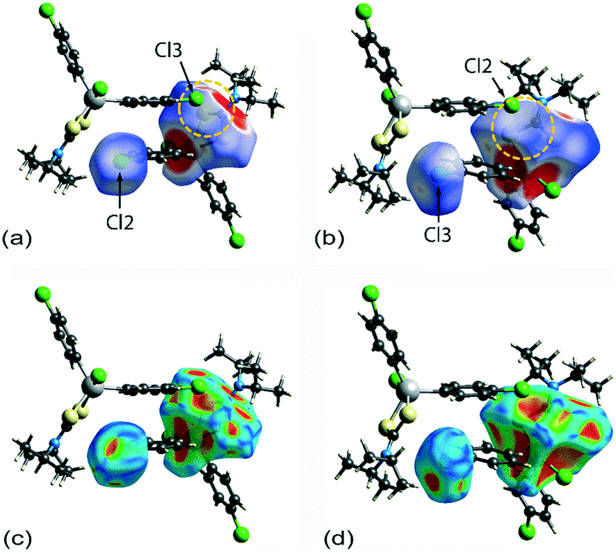
Two computational methods were used to examine the non-covalent contacts in the crystal of 1. Firstly, a plane-wave/pseudopotential calculation was carried out on the periodic structure using the projector augmented wave (PAW) method55 implemented in Quantum ESPRESSO,56 with plane-wave and density cut-off values of 60 Ry and 600 Ry, respectively, and a 2 × 2 × 2 uniform k-point grid. The non-covalent interaction (NCI) plots57,58 were obtained using the critic2 program.59 The calculations provide a qualitative indication of the nature of interactions between molecules in a crystal through the visualisation of the gradient iso-surface based on the electron-density derivatives obtained from the wavefunction calculation. The results are manifested in a three-colour scheme, that is, blue, red and green for attractive, repulsive and weakly attractive interactions, respectively.The NCI plot calculated for the experimental structure in Fig. 3(a) indicates that there are only weak non-directional intermolecular interactions in the pair of symmetry-related molecules encompassing the two Cl(lone-pair)⋯π(chelate-ring) interactions. The π(chlorophenyl)⋯π(chlorophenyl)ii interaction between face-to-face phenyl rings is clearly evident, as well as the Cl(lone-pair)⋯π(chelate-ring)ii contact involving the Cl2 atom; symmetry operation in the crystal: (ii) 1½ − x, ½ + y, ½ − z. Less apparent is an interaction between the Cl3ii atom and the chelate-ring of the reference molecule, rather the attractive interaction in this region of structure appears to be primarily due to a Cl3ii⋯H6c–C6 contact, Table 1. The NCI plot shows that the Cl2(lone-pair)⋯π(chelate-ring)ii interaction is relatively weak. For comparative purposes, the NCI plot in Fig. 3(b) shows the contacts between two relatively distant molecules and highlights the weak, cooperative interactions formed between a methine group and the tin-bound chloride, i.e. C5–H5⋯Cl1v, and between a methyl group and the sulphur-S1 atom, i.e. C6–H6b⋯S1v, of a centrosymmetrically-related molecule; symmetry operation (v) ½ + x, ½ − y, ½ + z. The NCI plots calculated at 298 K exhibit essentially the same features and are qualitatively the same, see ESI† Fig. S4.
 | ||
| Fig. 3 Images of non-covalent interaction plot for 1 measured at 100 K, with the green regions indicating weakly attractive interactions, highlighting the: (a) Cl2(lone-pair)⋯π(chelate-ring)ii, π(chlorophenyl)⋯π(chlorophenyl)ii and Cl3ii⋯H6c–C6 interactions and (b) C5–H5⋯Clv and C6–H6b⋯S1v interactions; symmetry operations: (ii) 1½ − x, ½ + y, ½ − z and (v) ½ + x, ½ − y, ½ + z. | ||
A QTAIM analysis confirms the above conclusions. Fig. 4 shows the density critical points and the bond paths calculated from the gas-phase self-consistent wavefunction for the 100 K geometry; see ESI† Fig. S5 for the analogous plot for the 298 K data. A bond critical point and an associated bond path exist between the Cl2 atom and the S2ii atom of the chelate-ring, indicating a weak interaction between them. In addition, multiple bond paths exist between the π-rings and the terminal methyl groups and sulphur atoms. The results of the QTAIM analysis are therefore, consistent with the results obtained from the NCI plots.
 | ||
| Fig. 4 An image of QTAIM analysis for 1 measured at 100 K. Symmetry operation: (ii) 1½ − x, ½ + y, ½ − z. | ||
Having established the attractive, albeit weakly attractive, nature of the interactions within the two dimeric aggregates shown in Fig. 3, the strength of each of the identified interactions was estimated by calculating the gas-phase binding energies for the isolated dimeric aggregate. For this purpose, the Gaussian16 (ref. 60) program and the B3LYP-XDM method61,62 combined with the Def2TZVPP basis set63 and an “ultrafine” (99 × 590 pruned) integration grid were employed. The calculated binding energy for the aggregate shown in Fig. 3(a), representing the 100 K structure determination, amounts to 12.22 kcal mol−1, and for the dimer represented in Fig. 3(b), 7.10 kcal mol−1. The comparable values for the analysis conducted at 298 K are smaller, at 11.94 and 6.89 kcal mol−1, respectively, reflecting the tighter packing in the crystal measured at the lower temperature. Clearly, the dimer encompassing the two putative Cl(lone-pair)⋯π(chelate-ring) interactions is significantly more stable, partly owing to the presence of the off-set π ⋯π interaction. Using the same procedures as for the calculations herein, the binding energies for other hypothetical gas-phase dimers were also calculated. Thus, for an off-set, parallel benzene dimer, the energy computes to 2.53 kcal mol−1 (this is close to 2.65 kcal mol−1 calculated using a much higher level of theory64–66). In the second hypothetical dimer, where a chloride atom of a chloroform molecule is directed towards the ring centroid of a benzene molecule, the energy of stabilisation computes to 0.86 kcal mol−1. Given that interaction strengths corresponding to individual moieties cannot be disentangled absolutely from the rest of the intermolecular interations,67 only an estimate of the energy associated with the Cl(lone-pair)⋯π(chelate-ring) interaction can be made. It is estimated that the energy per Cl(lone-pair)⋯π(chelate-ring) interaction is in the vicinity of 3–4 kcal mol−1, and quite probably no more than 5 kcal mol−1. This energy is higher than for a Cl⋯benzene interaction owing to the greater number of electrons involved in the contact.
Hirshfeld surface analysis
For Hirshfeld surface mapping, the corresponding two-dimensional fingerprint plots as well as pairwise interaction calculations were performed using Crystal Explorer 17 (ref. 68) using established methods,69 with the atomic coordinates determined by X-ray crystallography at 100 and 298 K being used as the input but with the X–H bond lengths adjusted to their neutron-derived values.70 The Hirshfeld surface analysis was performed to identify important surface contacts and to ascertain the influence of changing temperature on these. The dnorm-mapped surfaces shown in Fig. 5 indicate that the decrease in temperature (298 to 100 K) has indeed led to some qualitative changes in the manifestation of the interactions. Thus, at room temperature, the surface of 1 exhibits several red spots of weak intensity, Fig. 5(a), corresponding to the presence of close contacts70 with separations shorter than the sum of the respective van der Waals (vdW) radii,47 that is, due to methyl-C6–H6c⋯Cl3(chlorophenyl)ii and chlorophenyl-C12–H12⋯Cl1(chlorido)iv interactions; symmetry operations (ii) 1½ − x, ½ + y, ½ − z and (iv) 2 − x, 1 − y, 1 − z. Upon cooling to 100 K, the red spots are observed with enhanced intensity signifying relatively closer contact distances compared to the 298 K structure determination; this is verified by the systematic reduction in the contact distances listed in Table 3. Additional features are also noted in Fig. 5(b)cf.Fig. 5(a), which are attributed to the methyl-C7–H7c⋯C17(chlorophenyl)i short contact; symmetry operations (i) −1 + x, y, z. This observation contrasts with the room temperature analysis where the same contact is represented by a white spot indicative of a contact distance equivalent to a van der Waals separation.70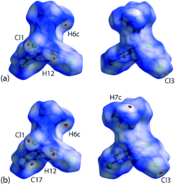 | ||
| Fig. 5 Two views of the Hirshfeld surface mapped over dnorm within the range −0.0099 to 1.0499 arbitrary units for 1 measured at (a) 298 K and (b) 100 K. | ||
| Contact | 100 K | 298 K | Symmetry operation |
|---|---|---|---|
| C6–H6c⋯Cl3ii | 2.73 | 2.78 | 1½ − x, ½ + y, ½ − z |
| C12–H12⋯Cl1iv | 2.75 | 2.79 | 2 − x, 1 − y, 1 − z |
| C7–H7c⋯C17i | 2.70 | 2.80 | −1 + x, y, z |
It is noteworthy from the views of the dnorm in Fig. 6(a) and (b) that white regions are observed around the vicinity of the SnS2C chelate-ring as well as around the chlorophenyl-Cl atoms, thereby suggesting the existence of weak Cl(lone-pair)⋯π(chelate-ring) interactions. The corresponding Hirshfeld surface mapped over the shape-index for the chelate-ring and chloride in Fig. 6(c) and (d) indicates that there is shape-complementarity between the fragments which provides further evidence for these close contacts.
 | ||
| Fig. 6 Hirshfeld surfaces calculated for 1 (100 K), showing (a) and (b) the dnorm-maps (range: −0.0099 to 1.0499 arbitrary units) for the chelate-ring fragment and pendent chloride atoms participating in the π(chelate-ring) interactions, and (c) and (d) equivalent images for the Hirshfeld surface mapped over the shape index property (range: −1.0 to 1.0 arbitrary units). | ||
Molecular electrostatic mapping
The molecular electrostatic mapping (MEP) was performed to further characterise the identified close contacts by mapping the electrostatic potential onto the corresponding Hirshfeld surfaces through the TONTO71 quantum modelling package as available in Crystal Explorer 17 (ref .68) using the Becke three-parameter Lee–Yang–Parr (B3LYP) hybrid functionals72 with the DGDZVP basis set.73,74 The MEP map shows that both chlorophenyl–chloride atoms have negative potential which surround the respective atom (Vs = −9.91 to −12.11 kcal mol−1 for Cl2; Vs = −8.28 to −9.54 kcal mol−1 for Cl3) while the σ-hole at the polar region of the atoms is slightly positive in potential (Vs = 0.50 to 1.08 kcal mol−1 for Cl2; Vs = 4.71 to 5.27 kcal mol−1 for Cl3), as evidenced by the corresponding red and pale-blue regions shown in Fig. 7; a full listing is given in ESI† Table S2.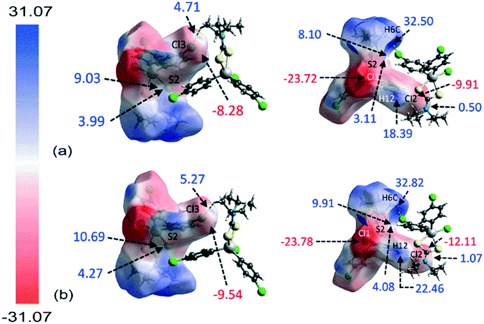 | ||
| Fig. 7 The two views of the calculated electrostatic potential mapped onto the Hirshfeld surfaces of 1 analysed at (a) 298 K and (b) 100 K, showing the potential at the point of contact for the Cl(lone-pair)⋯π(chelate-ring) interaction along with other identified interacting sites within the range −31.07 to 31.07 kcal mol−1. | ||
Crucially, the four-membered SnSCS chelate-ring displays a positive potential near the centre of the ring with the potential value ranging from about 8.10 to 10.69 kcal mol−1, corresponding to the π-hole of the chelate-ring. Judging from the charge-complemented potential values, the Cl(lone-pair)⋯π(chelate-ring) interactions are therefore established to be attractive in nature. As indicated in the QTAIM analysis, a bond path is evident between the Cl2 atom and the S2 atom, being indicative of a Cl⋯S contact. This is shown to be due to a positive potential on the iso-density surface of the S2 atom with potential values within the range of 3.11 to 4.27 kcal mol−1. The other identified contacts are also found to be attractive in nature with complementary positive and negative potential charges at the point of contact with the exception of the H6c⋯Cl3ii contact. Here, the potential charge values are calculated to lie in the range of about 4.71 to 5.27 kcal mol−1 for Cl3 and 32.50 to 32.82 kcal mol−1 for H6c, indicating each atom to be electropositive. The interaction is thought to arise owing to the large charge deviation between the Cl3 and H6c atoms that leads to a certain degree of dispersion force between the interacting atoms.
The MEP study reveals that in general the 100 K structure has a greater electrostatic potential than the room temperature analysis apparently due to the effect of temperature during data collection. This reflects the reduced contact distances which enhance the electron-polarisation between the interacting atoms that eventually lead to the increase in electrostatic potential as the temperature decreases from 298 to 100 K.
Quantification of intermolecular contacts
An assessment of the different surface contacts for 1 was achieved through an analysis of the two-dimensional fingerprint plots to better understand the differences in the distribution patterns for the crystals at 100 and 298 K. The analysis shows almost similar distributions with H⋯H contacts being the most dominant contact of about 41%. This is followed by H⋯Cl/Cl⋯H (27–28%), H⋯C/C⋯H (16–17%), H⋯S/S⋯H (6%), Cl⋯C/C⋯Cl (4%), C⋯C (3%) and other minor contacts with the sum of the contributions being less than 2%, see ESI† Table S3 for full details. A similar observation is made for the fingerprint plots in which the overall as well as the respective decomposed fingerprint profiles closely resemble each other with the exception that slightly shorter di + de contact distances are noted, as expected, for the 100 K determination. For instance, the H⋯Cl/Cl⋯H and H⋯C/C⋯H contacts for the 100 K analysis display spikes in the corresponding profiles with di + de distances tipped at 2.73 Å (corresponding to the H6c⋯Cl3ii contact) and 2.70 Å (H7c⋯C17i), respectively, compared with 2.78 and 2.80 Å for the equivalent contacts for the 298 K analysis, Table 3 and Fig. 8. Among all contacts, only the H⋯Cl/Cl⋯H and H⋯C/C⋯H contacts exhibit di + de contact distances shorter than the sum of the respective van der Waals radii. To conclude, the variation of temperature in the X-ray experiments exerts little influence on the distribution of the various contacts in the respective crystals.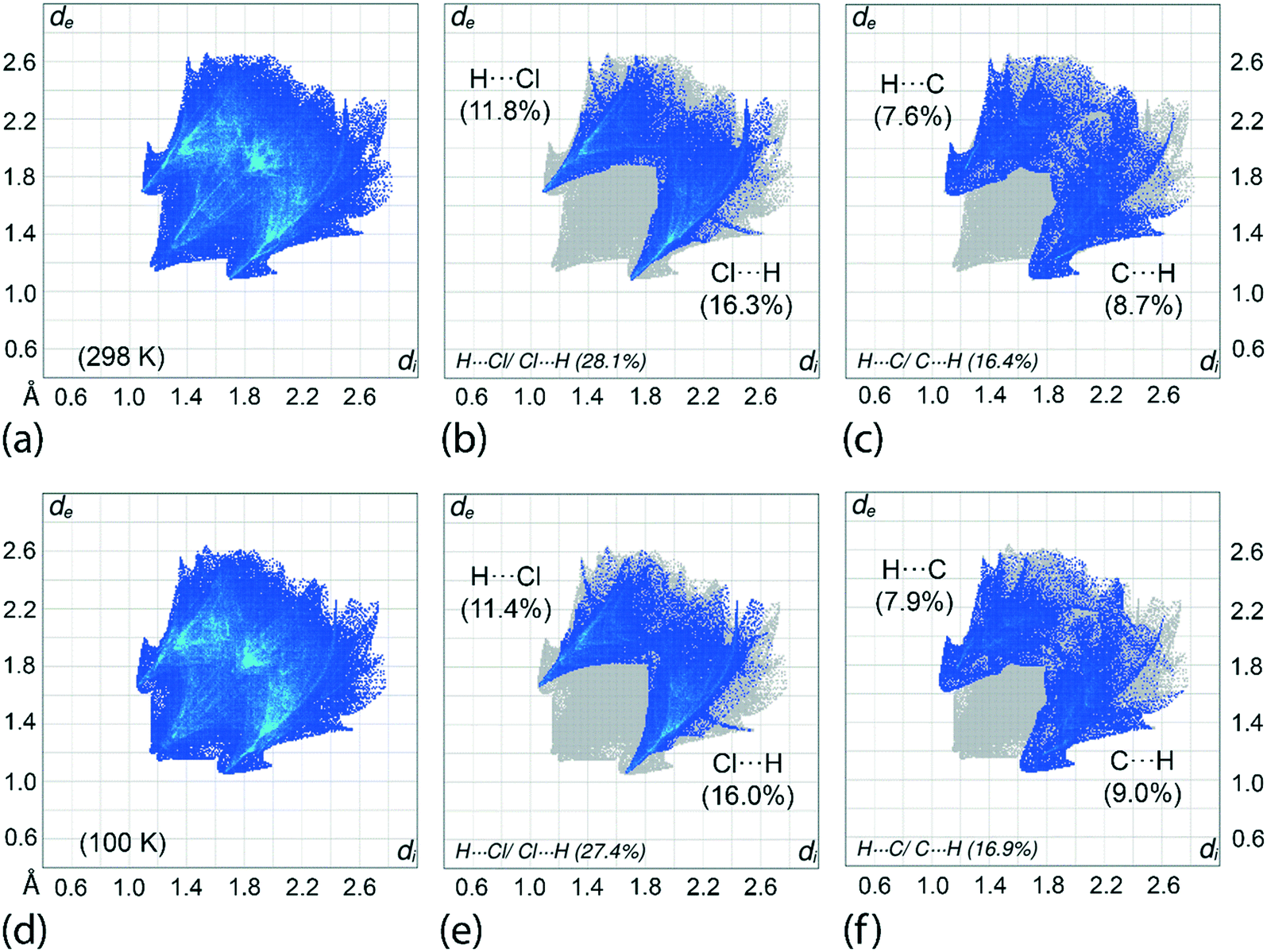 | ||
| Fig. 8 (a) The overall two-dimensional fingerprint plot and decomposed fingerprint plots delineated into (b) H⋯Cl/Cl⋯H and (c) H⋯C/C⋯H contacts for 1 determined at 298 K; (d)–(f) equivalent fingerprint plots for the analysis of 1 at 100 K. The percentage contributions are indicated within each plot. | ||
Interaction energies and energy frameworks
The strength of each interaction as identified from the Hirshfeld surface analysis was assessed with a CE-B3LYP/DGDZVP model available in Crystal Explorer 17.68 The total intermolecular energy, Etotal, is the sum of the energies of four main components, comprising electrostatic (Eelectro), polarisation (Epolar), dispersion (Edis) and exchange-repulsion (Erep).75 The model was validated against the B3LYP-D2/6-31G(d,p) counterpoise corrected energy model as well as the benchmark CCSD(T)/CBS model with considerable accuracy.76 The energy frameworks were computed for a cluster of 2 × 2 × 2 unit cells for 1 with the energy cut-off being set to 1.91 kcal mol−1. Finally, the total energy was obtained for a cluster of molecules within a 25 Å radius from a selected reference molecule through the same level of theory and basis set model, of which the lattice energy, Elattice, for the corresponding crystal structures was calculated using the following equation:77where the second term is the cell dipole energy correction, with ρcell being the vector sum of the molecular dipole moments, Vcell is the volume and Z is the number of formula units in the unit cell. Typically, the cell dipole energy correction is negligible (<0.24 kcal mol−1) for unit cells with small dipole moments.78
The results of the analysis are summarised in Table 4 (100 K) and ESI† Table S4 (298 K data). Consistent with the observations above, 1 has relatively greater interaction energy (Eint) at 100 K as compared to 298 K. Overall, the combination of C6–H6c⋯Cl3ii, Cg(C8–C13)⋯Cg(C14–C19)ii, Cl2⋯π(chelate-ring)ii, Cl3iii⋯π(chelate-ring), Cl2⋯S2ii and Cl3ii⋯S2 contacts within a pair of molecules results in the greatest Eint of −11.50 kcal mol−1, which is close to the −12.22 kcal mol−1 determined by theory (see above). This is followed closely by the sum of the C7–H7c⋯C17i and C7⋯π(C14–C19)i interactions which result in a combined Eint of −11.04 kcal mol−1. On the other hand, the pairwise C12–H12⋯Cl1 contacts results in the weakest Eint of −3.94 kcal mol−1.
| Contact | E electro | E polar | E dis | E rep | E total | Symmetry operation |
|---|---|---|---|---|---|---|
| a Scale factors were determined based on the literature procedure75 and determined to be 1.057, 0.740, 0.871 and 0.618 for Eelectrostatic (Eelectro), Epolarisation (Epolar), Edispersion (Edis) and Erepulsion (Erep), respectively. | ||||||
| C6–H6c⋯Cl3ii + Cg(C8–C13)⋯Cg(C14–C19)ii + Cl2⋯π(chelate-ring)ii + Cl3ii⋯π(chelate-ring) + Cl2⋯S2ii + Cl3ii⋯S2 | −7.9 | −0.8 | −13.9 | 11.1 | −11.5 | 1½ − x, ½ + y, ½ − z |
| C7–H7c⋯C17i + C7⋯π(C14–C19)i | −5.6 | −0.7 | −11.1 | 6.4 | −11.0 | −1 + x, y, z |
| C12–H12⋯Cl1iv (×2) | −2.9 | −0.6 | −3.3 | 2.9 | −3.9 | 2 − x, 1 − y, 1 − z |
| Total energies | ||||||
| 100 K | −25.81 | −4.59 | −57.03 | 33.66 | −53.77 | |
| 298 K | −20.72 | −4.16 | −50.31 | 25.74 | −49.45 | |
The crystal 1 is mainly stabilised by dispersion forces which are complemented by relatively weak electrostatic forces. The combination of these leads to a directional ladder-like topology as shown through the simulated energy frameworks of Fig. 9. The simulation shows that at 100 K, 1 is slightly more stable than 1 determined at 298 K, see ESI† Fig. S6, as reflected in the relatively thicker rods in the energy framework presented at the same scale factor. A crystal lattice energy calculation for a molecular cluster within 25 Å of the reference molecules reveals that 1, at 100 K, has a lattice energy of −26.78 kcal mol−1 which is about 1.75 kcal mol−1 more stable compared to that of −25.03 kcal mol−1 for 1 determined at 298 K.
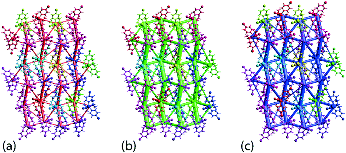 | ||
| Fig. 9 Simulated energy framework for 1 measured at 100 K within 2 × 2 × 2 unit-cells, showing the decomposed frameworks delineated into (a) electrostatic or coulombic potential (red), (b) dispersion force (green) and (c) overall energy framework. The frameworks are drawn at a scale of 150 with an energy cut-off of 1.91 kcal mol−1. | ||
The dithiocarbamate anion is well-known to form an aromatic ring when coordinated to metal centres, an observation related to its strong chelating ability due to the nearly 40% contribution of the canonical form with formal negative charges on each sulphur atom, i.e.(2−)S2CN(+)R2, to the overall electronic structure of the anion. The metallo-aromatic ring thus formed is now well-established to function as an acceptor of C–H⋯π(chelate-ring) interactions as demonstrated in a recent bibliographic review of the first-row transition metal dithiocarbamates.79 Here, it was confirmed that C–H⋯π(chelate-ring) interactions occurred in complexes of varying coordination numbers and geometries, and reached a maximum adoption of approximately 37% in square-planar nickel(II) complexes.79 With this in mind, and given that C–Cl⋯π(arene) interactions are well understood, it might be expected that analogous C–Cl⋯π(chelate-ring) interactions in metal dithiocarbamates are possible. Indeed, in 1, based on distance considerations, it is likely that C–Cl⋯π(chelate-ring) interactions participate in the stabilisation of the molecular packing. Energy calculations suggest that the contribution to the stability of the molecular packing is in the vicinity of 3–4 kcal mol−1, a value greater than for more conventional C–Cl⋯π(arene) and C–H⋯π(arene) interactions. In 1, the best description of the interaction, based on the angle subtended at the chloride atom, is a Cl(lone-pair)⋯π(chelate-ring) interaction rather than a Cl(σ-hole)⋯π(chelate-ring) interaction. The question remains: how prevalent are these interactions in the crystallographic literature.
To address this question, a search of the Cambridge Structural Database80 (CSD version 5.41, August 2020 update) was conducted employing ConQuest (version 2.0.4).81 The CSD was searched for Cl⋯ring-centroid(SnS2C chelate-ring) contacts less than 3.92 Å, being the sum of the van der Waals radii of the chloride and the largest atom in the chelate-ring, i.e. tin, following the recent literature precedent.79 Three structures were returned from this search, namely [SnCl{MeOC(O)CH2CH2}2(S2CNMe2)],82 [SnCl2(n-Bu)(S2CNEt2)]83 and [SnCl(4-ClC6H4CH2)2{S2CN(Me)CH2Ph}].84 The Cl⋯ring-centroid contacts involve tin-bound chlorido atoms in the first two structures and a phenyl-bound chloride atom in the latter. The Cl⋯ring-centroid separations in the three structures at 3.86, 3.88 and 3.76 Å, respectively, are all longer than the shorter contact observed in 1. Placed in context, there are over 100 tin dithiocarbamate structures included in the CSD having at least one dithiocarbamate ligand and one chloride atom. This rather low adoption rate for C–Cl⋯π(chelate-ring) interactions suggests that these are unlikely to be an important design element in crystal engineering and leads to the obvious question whether these interactions arise as a consequence of global molecular packing considerations.85–88
Conclusions
A detailed analysis of the supramolecular association in the crystal of [SnCl(4-ClC6H4)2{S2CN(i-Pr)2}] reveals a variety of conventional non-covalent intermolecular interactions as well as hitherto undescribed C–Cl⋯π(chelate-ring) interactions based on distance criteria. These occur in a side-on fashion rather than head-on and therefore are best described as C–Cl(lone-pair)⋯π(chelate-ring) interactions. Theory suggests that the energy of stabilisation provided by these interactions is small, being no more than 3–4 kcal mol−1 but, reflecting the involvement of a greater number of electrons in the interacting residues, is greater than the stabilising energies for the more well-established C–Cl⋯π(arene) and C–Cl(lone-pair)⋯π(arene) interactions. Related contacts in dithiocarbamate chemistry are comparatively rare but C–Cl⋯π(chelate-ring) interactions need to be added to the lexicon of supramolecular association found in the crystals of metal-based compounds.Conflicts of interest
There are no conflicts to declare.Acknowledgements
The authors gratefully acknowledge Sunway University Sdn Bhd (Grant no. STR-RCTR-RCCM-001-2019) for support of crystallographic studies. AOR thanks the Spanish government (MICINN and AEI) for financial support (projects PGC2018-097520-A-100 and RED2018-102612-T) and the MALTA Consolider supercomputing centre for computational resources.References
- E. R. T. Tiekink and J. Zukerman-Schpector, The importance of pi-interactions in crystal engineering: Frontiers in Crystal Engineering, John Wiley & Sons, Ltd, 2012 Search PubMed.
- D. Quiñonero, C. Garau, C. Rotger, A. Frontera, P. Ballester, A. Costa and P. M. Deyà, Angew. Chem., Int. Ed., 2002, 41, 3389–3392 CrossRef.
- B. L. Schottel, H. T. Chifotides and K. R. Dunbar, Chem. Soc. Rev., 2008, 37, 68–83 RSC.
- M. Giese, M. Albrecht and K. Rissanen, Chem. Commun., 2016, 52, 1778–1795 RSC.
- J. Zhao, D. Yang, X.-J. Yang and B. Wu, Coord. Chem. Rev., 2019, 378, 415–444 CrossRef CAS.
- P. Molina, F. Zapata and A. Caballero, Chem. Rev., 2017, 117, 9907–9972 CrossRef CAS.
- D. Quiñonero, C. Garau, A. Frontera, P. Ballester, A. Costa and P. M. Deyà, Chem. Phys. Lett., 2002, 359, 486–492 CrossRef.
- S. E. Wheeler and J. W. G. Bloom, J. Phys. Chem. A, 2014, 118, 6133–6147 CrossRef CAS.
- C. Foroutan-Nejad, Z. Badri and R. Marek, Phys. Chem. Chem. Phys., 2015, 17, 30670–30679 RSC.
- P. Politzer, J. S. Murray and M. C. Concha, J. Mol. Model., 2007, 13, 643–650 CrossRef CAS.
- S. Scheiner, Int. J. Quantum Chem., 2013, 113, 1609–1620 CrossRef CAS.
- M. H. Kolar and P. Hobza, Chem. Rev., 2016, 116, 5155–5187 CrossRef CAS.
- H. Matter, M. Nazaré, S. Güessregen, D. W. Will, H. Schreuder, A. Bauer, M. Urmann, K. Ritter, M. Wagner and V. Wehner, Angew. Chem., Int. Ed., 2009, 48, 2911–2916 CrossRef CAS.
- H. Matter, M. Nazaré, S. Güssregen, E. R. T. Tiekink and J. Zukerman-Schpector, The importance of pi-interactions in crystal engineering: Frontiers in Crystal Engineering, John Wiley & Sons, Ltd, 2012, ch 8, pp. 187–232 Search PubMed.
- T. J. Tucker, S. F. Brady, W. C. Lumma, S. D. Lewis, S. J. Gardell, A. M. Naylor-Olsen, Y. Yan, J. T. Sisko, K. J. Stauffer, B. J. Lucas, J. J. Lynch, J. J. Cook, M. T. Stranieri, M. A. Holahan, E. A. Lyle, E. P. Baskin, I.-W. Chen, K. B. Dancheck, J. A. Krueger, C. M. Cooper and J. P. Vacca, J. Med. Chem., 1998, 41, 3210–3219 CrossRef CAS.
- S. Demeshko, S. Dechert and F. Meyer, J. Am. Chem. Soc., 2004, 126, 4508–4509 CrossRef CAS.
- Y. Lu, Y. Wang and W. Zhu, Phys. Chem. Chem. Phys., 2010, 12, 4543–4551 RSC.
- E. Danelius, H. Andersson, P. Jarvoll, K. Lood, J. Gräfenstein and M. Erdélyi, Biochemistry, 2017, 56, 3265–3272 CrossRef CAS.
- A. Priimagi, G. Cavallo, P. Metrangolo and G. Resnati, Acc. Chem. Res., 2013, 46, 2686–2695 CrossRef CAS.
- J. Noh, S. Jung, D. G. Koo, G. Kim, K. S. Choi, J. Park, T. J. Shin, C. Yang and J. Park, Sci. Rep., 2018, 8, 14448 CrossRef.
- E. Kanao, T. Morinaga, T. Kubo, T. Naito, T. Matsumoto, T. Sano, H. Maki, M. Yanf and K. Otsuka, Chem. Sci., 2020, 11, 409–418 RSC.
- A. Mukherjee, S. Tothadi and G. R. Desiraju, Acc. Chem. Res., 2014, 47, 2514–2524 CrossRef CAS.
- H. Masui, Coord. Chem. Rev., 2001, 219–221, 957–992 CrossRef CAS.
- F. Feixas, E. Matito, J. Poater and M. Solà, WIREs Comput. Mol. Sci., 2013, 3, 105–122 CrossRef CAS.
- D. Chen, C. S. Lai and E. R. T. Tiekink, Z. Kristallogr., 2002, 218, 747–752 Search PubMed.
- D. Sredojević, G. A. Bogdanović, Z. D. Tomić and S. D. Zarić, CrystEngComm, 2007, 9, 793–798 RSC.
- E. R. T. Tiekink and J. Zukerman-Schpector, Chem. Commun., 2011, 47, 6623–6625 RSC.
- Z. D. Tomić, D. N. Sredojević and S. D. Zarić, Cryst. Growth Des., 2006, 6, 29–31 CrossRef.
- D. Sredojević, D. Z. Vojislavljević, Z. D. Tomić and S. D. Zarić, Acta Crystallogr., Sect. B: Struct. Sci., 2012, 68, 261–265 CrossRef.
- D. P. Malenov, G. V. Janjiae, V. B. Medakoviae, M. B. Hall and S. D. Zarić, Coord. Chem. Rev., 2017, 345, 318–341 CrossRef CAS.
- D. N. Sredojević, Z. D. Tomić and S. D. Zarić, Cryst. Growth Des., 2010, 10, 3901–3908 CrossRef.
- D. P. Malenov and S. D. Zarić, Dalton Trans., 2019, 48, 6328–6332 RSC.
- E. R. T. Tiekink, Coord. Chem. Rev., 2017, 345, 219–228 CrossRef.
- E. R. T. Tiekink, Appl. Organomet. Chem., 2008, 22, 533–550 CrossRef CAS.
- B. Dutta, S. M. Pratik, S. Jana, C. Sinha, A. Datta and M. H. Mir, ChemistrySelect, 2018, 3, 4289–4291 CrossRef CAS.
- K. Sisido, Y. Takeda and Z. Kinugawa, J. Am. Chem. Soc., 1961, 83, 538–541 CrossRef.
- Rigaku Oxford Diffraction, CrysAlis PRO, Yarnton, Oxfordshire, England, 2017 Search PubMed.
- G. M. Sheldrick, A short history of SHELX, Acta Crystallogr., Sect. A: Found. Crystallogr., 2008, 64, 112–122 CrossRef CAS.
- G. M. Sheldrick, Crystal structure refinement with SHELXL, Acta Crystallogr., Sect. C: Struct. Chem., 2015, 71, 3–8 Search PubMed.
- L. J. Farrugia, WinGX and ORTEP for Windows: an update, J. Appl. Crystallogr., 2012, 45, 849–854 CrossRef CAS.
- A. L. Spek, Acta Crystallogr., Sect. E: Crystallogr. Commun., 2020, 76, 1–11 CrossRef CAS.
- K. Brandenburg, DIAMOND, Crystal Impact GbR, Bonn, Germany, 2006 Search PubMed.
- A. W. Addison, T. N. Rao, J. Reedijk, J. van Rijn and G. C. Verschoor, J. Chem. Soc., Dalton Trans., 1984, 1349–1356 RSC.
- M. A. Buntine, V. J. Hall, F. J. Kosovel and E. R. T. Tiekink, J. Phys. Chem. A, 1998, 102, 2472–2482 CrossRef CAS.
- E. R. T. Tiekink, V. J. Hall and M. A. Buntine, Z. Kristallogr., 1999, 214, 124–134 CAS.
- A. Faizah, A. Muthalib, I. Baba, H. Khaledi, H. M. Ali and E. R. T. Tiekink, Z. Kristallogr., 2014, 229, 39–46 Search PubMed.
- A. Bondi, J. Phys. Chem., 1964, 68, 441–451 CrossRef CAS.
- C. F. Macrae, I. Sovago, S. J. Cottrell, P. T. A. Galek, P. McCabe, E. Pidcock, M. Platings, G. P. Shields, J. S. Stevens, M. Towler and P. A. Wood, J. Appl. Crystallogr., 2020, 53, 226–235 CrossRef CAS.
- A. Mukherjee and G. R. Desiraju, IUCrJ, 2014, 1, 49–60 CrossRef CAS.
- J. D. Dunitz and R. Taylor, Chem. – Eur. J., 1997, 3, 89–98 CrossRef CAS.
- I. Caracelli, J. Zukerman-Schpector and E. R. T. Tiekink, Coord. Chem. Rev., 2012, 256, 412–438 CrossRef CAS.
- A. Bauzá, R. Ramis and A. Frontera, J. Phys. Chem. A, 2014, 118, 2827–2834 CrossRef.
- Y. N. Imai, Y. Inoue, I. Nakanishi and K. Kitaura, Protein Sci., 2008, 7, 1129–1137 CrossRef.
- Y. N. Imai, Y. Inoue, I. Nakanishi and K. Kitaura, QSAR Comb. Sci., 2009, 28, 869–873 CrossRef CAS.
- P. E. Blöchl, Phys. Rev. B, 1994, 50, 17953–17979 CrossRef.
- P. Giannozzi, O. Andreussi, T. Brumme, O. Bunau, M. Buongiorno Nardelli, M. Calandra, R. Car, C. Cavazzoni, D. Ceresoli, M. Cococcioni, N. Colonna, I. Carnimeo, A. Dal Corso, S. de Gironcoli, P. Delugas, R. DiStasio, A. Ferretti, A. Floris, G. Fratesi, G. Fugallo, R. Gebauer, U. Gerstmann, F. Giustino, T. Gorni, J. Jia, M. Kawamura, H.-Y. Ko, A. Kokalj, E. Küçükbenli, M. Lazzeri, M. Marsili, N. Marzari, F. Mauri, N. L. Nguyen, H.-V. Nguyen, A. Otero-de-la-Roza, L. Paulatto, S. Ponce, D. Rocca, R. Sabatini, B. Santra, M. Schlipf, A. Seitsonen, A. Smogunov, I. Timrov, T. Thonhauser, P. Umari, N. Vast and S. Baroni, J. Phys.: Condens. Matter, 2017, 29, 465901 CrossRef CAS.
- E. R. Johnson, S. Keinan, P. Mori-Sánchez, J. Contreras-García, A. J. Cohen and W. Yang, J. Am. Chem. Soc., 2010, 132, 6498–6506 CrossRef CAS.
- A. Otero-de-la-Roza, E. R. Johnson and J. Contreras-García, Phys. Chem. Chem. Phys., 2012, 14, 12165–12172 RSC.
- A. Otero-de-la-Roza, E. R. Johnson and V. Luaña, Comput. Phys. Commun., 2014, 185, 1007–1018 CrossRef CAS.
- M. J. Frisch, G. W. Trucks, H. B. Schlegel, G. E. Scuseria, M. A. Robb, J. R. Cheeseman, G. Scalmani, V. Barone, G. A. Petersson, H. Nakatsuji, X. Li, M. Caricato, A. V. Marenich, J. Bloino, B. G. Janesko, R. Gomperts, B. Mennucci, H. P. Hratchian, J. V. Ortiz, A. F. Izmaylov, J. L. Sonnenberg, D. Williams-Young, F. Ding, F. Lipparini, F. Egidi, J. Goings, B. Peng, A. Petrone, T. Henderson, D. Ranasinghe, V. G. Zakrzewski, J. Gao, N. Rega, G. Zheng, W. Liang, M. Hada, M. Ehara, K. Toyota, R. Fukuda, J. Hasegawa, M. Ishida, T. Nakajima, Y. Honda, O. Kitao, H. Nakai, T. Vreven, K. Throssell, J. A. Montgomery, Jr., J. E. Peralta, F. Ogliaro, M. J. Bearpark, J. J. Heyd, E. N. Brothers, K. N. Kudin, V. N. Staroverov, T. A. Keith, R. Kobayashi, J. Normand, K. Raghavachari, A. P. Rendell, J. C. Burant, S. S. Iyengar, J. Tomasi, M. Cossi, J. M. Millam, M. Klene, C. Adamo, R. Cammi, J. W. Ochterski, R. L. Martin, K. Morokuma, O. Farkas, J. B. Foresman and D. J. Fox, Gaussian 16, Gaussian, Inc., Wallingford CT, 2016 Search PubMed.
- A. D. Becke and E. R. Johnson, J. Chem. Phys., 2007, 127, 154108 CrossRef.
- A. Otero-de-la-Roza and E. R. Johnson, J. Chem. Phys., 2012, 136, 174109 CrossRef CAS.
- F. Weigend and R. Ahlrichs, Phys. Chem. Chem. Phys., 2005, 7, 3297–3305 RSC.
- P. Jurečka, J. Šponer, J. Černýa and P. Hobza, Phys. Chem. Chem. Phys., 2006, 8, 1985–1993 RSC.
- M. S. Marshall, L. A. Burns and C. D. Sherrill, J. Chem. Phys., 2011, 135, 194102 CrossRef.
- R. Podeszwa, K. Patkowski and K. Szalewicz, Phys. Chem. Chem. Phys., 2010, 12, 5974–5979 RSC.
- A. S. Mahadevi and G. N. Sastry, Chem. Rev., 2016, 116, 2775–2825 CrossRef CAS.
- S. K. Wolff, D. J. Grimwood, J. J. McKinnon, M. J. Turner, D. Jayatilaka and M. A. Spackman, Crystal Explorer (Version 17), University of Western Australia, 2012 Search PubMed.
- S. L. Tan, M. M. Jotani and E. R. T. Tiekink, Acta Crystallogr., Sect. E: Crystallogr. Commun., 2019, 75, 308–318 CrossRef CAS.
- M. A. Spackman and D. Jayatilaka, CrystEngComm, 2009, 11, 19–32 RSC.
- D. Jayatilaka and D. J. Grimwood, Comput. Sci. ICCS, 2003, 4, 142–151 Search PubMed.
- A. D. Becke, J. Chem. Phys., 1993, 98, 5648–5652 CrossRef CAS.
- N. Godbout, D. R. Salahub, J. Andzelm and E. Wimmer, Can. J. Chem., 1992, 70, 560–571 CrossRef CAS.
- C. Sosa, J. Andzelm, B. C. Elkin, E. Wimmer, K. D. Dobbs and D. A. Dixon, J. Phys. Chem., 1992, 96, 6630–6636 CrossRef CAS.
- C. F. Mackenzie, P. R. Spackman, D. Jayatilaka and M. A. Spackman, IUCrJ, 2017, 4, 575–587 CrossRef CAS.
- M. J. Turner, S. Grabowsky, D. Jayatilaka and M. A. Spackman, J. Phys. Chem. Lett., 2014, 5, 4249–4255 CrossRef CAS.
- S. P. Thomas, P. R. Spackman, D. Jayatilaka and M. A. Spackman, J. Chem. Theory Comput., 2018, 14, 1614–1623 CrossRef CAS.
- L. Maschio, B. Civalleri, P. Ugliengo and A. Gavezzotti, J. Phys. Chem. A, 2011, 115, 11179–11186 CrossRef CAS.
- E. R. T. Tiekink, CrystEngComm, 2020, 22, 7308–7333 RSC.
- R. Taylor and P. A. Wood, Chem. Rev., 2019, 119, 9427–9477 CrossRef CAS.
- I. J. Bruno, J. C. Cole, P. R. Edgington, M. Kessler, C. F. Macrae, P. McCabe, J. Pearson and R. Taylor, Acta Crystallogr., Sect. B: Struct. Sci., Cryst. Eng. Mater., 2002, 58, 389–397 CrossRef.
- O.-S. Jung, J. H. Jeong and Y. S. Sohn, Organometallics, 1991, 10, 2217–2221 CrossRef CAS.
- T. G. Hibbert, M. F. Mahon and K. C. Molloy, Main Group Met. Chem., 1999, 22, 235–241 CAS.
- K. M. Lo, L. S. Mun and E. R. T. Tiekink, Z. Kristallogr. - New Cryst. Struct., 2020, 235, 647–649 CAS.
- A. Gavezzotti, Acc. Chem. Res., 1994, 27, 309–314 CrossRef CAS.
- J. D. Dunitz and A. Gavezzotti, Acc. Chem. Res., 1999, 32, 677–684 CrossRef CAS.
- J. D. Dunitz and A. Gavezzotti, Chem. Soc. Rev., 2009, 38, 2622–2633 RSC.
- E. R. T. Tiekink, Chem. Commun., 2014, 50, 11079–11082 RSC.
Footnote |
| † Electronic supplementary information (ESI) available: Crystallographic data, electrostatic potential charge deviations, Hirshfeld surface contributions, interaction energies, PXRD and plots of unit-cell parameters, crystal packing overlay, NCI plots, QTAIM results and energy frameworks. CCDC 2036031–2036036 contain the supplementary crystallographic data for this paper. For ESI and crystallographic data in CIF or other electronic format see DOI: 10.1039/d0ce01478h |
| This journal is © The Royal Society of Chemistry 2021 |