 Open Access Article
Creative Commons Attribution 3.0 Unported Licence
High temperature supercapacitors using water-in-salt electrolytes: stability above 100 °C†
Lewis W.
Le Fevre
abc,
Andinet
Ejigu
bc,
Rebecca
Todd
a,
Andrew J.
Forsyth
a and
Robert A. W.
Dryfe
 *bc
*bc
aDepartment of Electrical and Electronic Engineering, The University of Manchester, Manchester, M13 9PL, UK
bDepartment of Chemistry, The University of Manchester, Manchester, M13 9PL, UK. E-mail: robert.dryfe@manchester.ac.uk
cNational Graphene Institute, The University of Manchester, Manchester, M13 9PL, UK
First published on 27th April 2021
Abstract
The high temperature performance of water-in-salt electrolytes was investigated using a carbon-based electrode with commercial cell components. Supercapacitors using 21 m Li bis(trifluoromethylsulphonyl)imide (TFSI) and 21 m LiTFSI + 7 m Li trifluoromethanesulphonyl electrolytes are shown to operate at a voltage of 2 V at 100 °C and 120 °C, respectively, with gravimetric capacitances exceeding 100 F g−1.
Supercapacitors are electrochemical devices which store energy via ion adsorption at an electrode/electrolyte interface. As a result, supercapacitors can stay operational for millions of cycles and are able to charge/discharge rapidly making them ideal candidates for high power applications.1–3 Furthermore, supercapacitors which are capable of operation at elevated temperatures (>60 °C) are in increasing demand due to applications in hybrid electric vehicles, military devices, oil drilling, mining and the aerospace industry.4–7 The main limitation on the operating temperature of current supercapacitor technologies is the electrolyte. Commercial supercapacitors based on organic electrolytes, with acetonitrile or propylene carbonate as solvents, are not suitable for high temperature applications due to the high flammability of the solvent which limits the safe operating temperature of these devices to ∼60–70 °C.8 Therefore, to achieve safe operation at temperatures >70 °C, alternative electrolytes are required.
An obvious thermally stable and non-flammable solvent is water. Standard aqueous electrolytes such as 1 M H2SO4, 1 M Na2SO4 and 6 M KOH would be able to operate safely at ∼100 °C. These electrolytes do, however, have some limitations. Firstly, they have a limited potential window due to the relatively low electrochemical stability of water (thermodynamic limit of 1.23 V) which significantly limits the maximum energy density when compared to organic systems. Secondly, these aqueous electrolytes are corrosive to most metal current collectors used in organic supercapacitors. Therefore, standard aqueous electrolytes are not used in commercial systems.
Recent developments in aqueous lithium ion batteries have seen the utilisation of highly concentrated salt solutions otherwise known as water-in-salt (WiS) electrolytes. Suo et al. reported that a 21 m lithium bis(trifluoromethyl-sulphonyl)imide (LiTFSI) solution has an electrochemical window of 3 V, which is far higher than that of conventional aqueous electrolytes.9 Furthermore, it has also been shown that the electrochemical window could be extended to 3.1 V by dissolving an additional 7 m lithium trifluoromethanesulphonyl (LiTFO) in the 21 m LiTFSI solution, creating a water-in-bisalt (WiBS) electrolyte.10 Since this work there has been intensive research on WiS and WiBS electrolytes. This has seen the WiS/WiBS concept applied to many other energy storage systems such as zinc, sodium and potassium ion batteries as well as supercapacitors.11–15 Hasegawa et al. used 21 m LiTFSI electrolyte with monolithic porous carbon electrodes which were capable of reaching 2 V and above with good stability over ten thousand cycles.16 Moreover, the WiS electrolyte did not influence the gravimetric capacitance of the carbon electrodes, which stayed above 100 F g−1, a typical value for carbon electrodes in aqueous electrolytes.17 Therefore, the maximum energy density for these electrolytes is comparable with traditional organic systems. Additionally, Kuhnel et al. demonstrated that LiTFSI and LiTFO electrolytes are compatible with aluminium current collectors meaning no significant modifications are required for commercial implementation.18
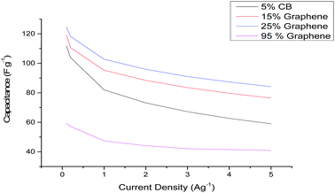
In this communication, we demonstrate the use of 21 m LiTFSI and 21 m LiTFSI + 7 m LiTFO electrolytes at elevated temperatures (>70 °C) using carbon based electrodes and standard commercial supercapacitor cell components. The majority of literature using various WiS electrolytes has focussed on porous carbon electrodes either containing activated carbon (AC), high-surface-area graphene or composites of the two materials.14,19 Therefore, initial electrode screening tests were performed on carbon-based electrodes at room temperature containing varying amounts of AC and graphene. The electrodes were coated onto aluminium current collectors using 5% (by weight) polyvinylidene fluoride (PVDF) binder. The graphene content of the electrodes was varied from 95 to 15% and was compared against a standard AC electrode containing 5% carbon black (CB). Fig. 1 shows the specific capacitance vs. current density of the various carbon electrodes chosen in the 21 m LiTFSI electrolyte. The fabricated supercapacitors were mass symmetric and operated up to 2 V.
It can be seen that the pure graphene electrode displays a low capacitance value when compared to AC-containing electrodes. The low specific capacitance values (∼60 F g−1) for a majority-graphene-containing electrode is expected and agrees with prior literature.20 This is due to the restacking of graphene materials during electrode fabrication which reduces the active specific surface area (SSA) of the electrode.21 There have been several different methods to try and prevent the restacking of the graphene sheets. However, the formation of graphene composite electrodes with other materials, such as AC or MoS2, has been shown to reduce this restacking.20,22 In the case of the AC-containing electrodes (5% CB, 15% or 25% graphene) an increase in the specific capacitance compared to the pure graphene electrode is observed. This is due to the relatively low SSA of the graphene powder (∼600 m2 g−1) when compared to the AC powder (∼2000 m2 g−1). Therefore, electrodes containing a majority of AC will have a larger SSA resulting in a larger specific capacitance.22 However, it can be seen that inclusion of 15% and 25% graphene within the electrode produces an increase in both the capacitance and rate performance. The improved rate performance is due to the increase of conductive material within the electrode, evidenced by the stepwise improvement in rate performance as the conductive additive content (CB or graphene) is increased from 5 to 95%. The improvement in the specific capacitance is attributed to improved adsorption of WiS/WiBS electrolyte ions on the surface of graphene compared to AC pores.
The observations are consistent with those of Mahankali et al., who demonstrated that the surface of a graphene sheet provides a higher areal capacitance than an AC pore when using 21 m LiTFSI.19 Based on the results displayed in Fig. 1, the 25% graphene-containing AC electrode was chosen for subsequent testing.
An important variable for supercapacitors is the operating voltage window (maximum voltage) which dictates the maximum energy density of the device. The voltage of a supercapacitor is typically dictated by the components’ electrochemically stable potential window (ESPW) at positive and negative potentials. Therefore, to maximise the voltage and lifetime of a supercapacitor, determination of the negative and positive electrode capacitance and ESPWs is required. This will allow the mass ratio of the positive and negative electrode to be determined, which, when applied to a device, allows for continuous operation within the ESPW of each electrode.23–25
The mass ratio of the 25% graphene electrode was determined using a method previously published.23 In summary, three electrode coin cells were created containing an over-weighted AC counter electrode, a 25% graphene working electrode and a silver wire quasi-reference electrode sandwiched between two pieces of separator. These three-electrode cells are used to determine the capacitance and potential limit of the electrodes when they are used as a positive and negative electrode separately. The potential limits from the three electrode cells were determined using the dwell current measured after 5 minutes at a constant potential between galvanostatic charge and discharge (GCD) cycles. This potential was increased stepwise (0.05 V) until a significant increase in the current value during the potential dwell was observed. The increase in current indicates that the ESPW of the electrolyte/electrode has been exceeded. The combination of the negative and positive ESPWs will also indicate the maximum possible voltage of the electrolyte/electrode system. The capacitance of the electrode was determined from the GCD profiles. This information allows the optimal mass ratio between the positive and negative electrodes to be determined using eqn (1).
 | (1) |
 and
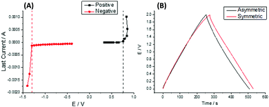
and  are the gravimetric capacitances of each electrode; and ΔE+ and ΔE− are the ESPWs of the positive and negative electrodes, respectively. Fig. 2A shows the dwell current vs. potential for the three-electrode coin cells using the 25% graphene working electrode in the 21 m LiTFSI electrolyte. From a sample set of three cells for each potential limit, average limits were calculated. These limits are indicated by black and red lines for the positive and negative limits respectively. The plots shown are of samples which provided the closest representations of the averaged limits. From averaged values of three cells, ΔE+ is 0.76 ± 0.08 V and ΔE− is 1.29 ± 0.06 V, giving an ESPW of 2.05 ± 0.14 V. Therefore, in a mass symmetric device the cell voltage would be limited by the positive electrode.
Consequently, the measured limits and capacitances found viaeqn (1) can be used to determine the optimal electrode mass ratio which was found to be 1.3. To verify the mass ratio, two-electrode coin cells were fabricated with symmetric (m+/m− = 1) and optimised asymmetric (m+/m− = 1.3) masses for GCD operation and cycling. Fig. 2B shows the GCD profiles of both coin cells when operated up to 2 V at 0.2 A g−1. The GCD profile of the symmetric cell showed a sign of degradative processes as a non-linear voltage response was seen above 1.8 V. In the case of the asymmetric device, a linear voltage response was seen up to 2 V indicating no degradation was occurring in this voltage range. The cycling performance over 10![[thin space (1/6-em)]](https://www.rsc.org/images/entities/char_2009.gif) 000 cycles at 1 A g−1 for the mass symmetric and asymmetric coin cells at 20 °C is displayed in the ESI† (Fig. S2). It can be seen that the asymmetric device displayed better capacitance retention due to the symmetric supercapacitor exceeding its ESPW during operation, thus validating the mass ratio obtained.
000 cycles at 1 A g−1 for the mass symmetric and asymmetric coin cells at 20 °C is displayed in the ESI† (Fig. S2). It can be seen that the asymmetric device displayed better capacitance retention due to the symmetric supercapacitor exceeding its ESPW during operation, thus validating the mass ratio obtained.
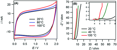
The mass-balanced 25% graphene supercapacitor was used to probe the performance of the 21 m LiTFSI electrolyte at elevated temperatures. Fig. 3A shows the cyclic voltammograms (CV) for several temperatures ranging from 20 °C to 100 °C for the mass-balanced, 25% graphene electrode. When the temperature was increased above 100 °C, cell failure was observed due to evaporation of the electrolyte. It can be seen that the CV current response increased stepwise with temperature. This is due to an increase in the capacitance of the cell at elevated temperatures (data shown in the ESI,† Fig. S3(A)). The improvement in capacitance corresponds to a stepwise increase in the energy density from 59.4 W h kg−1 (at 20 °C) to 70.6 W h kg−1 (at 100 °C) The increase in capacitance is due to a lowering of the viscosity and associated increase in access to micropores by the electrolyte.7,26 This improvement in the viscosity and conductivity is also seen in the Nyquist plots (Fig. 3B). The temperature increase causes a reduction in the solution and charge transfer resistances.
These decreases in resistance values indicate that the power capability of the supercapacitors would improve with increased temperature, an effect seen for high temperature ionic liquid electrolytes.26,27
However, it should be noted that the ESPW of the device decreases with increases in temperature. This can be seen as when the temperature increased the CVs (Fig. 3A) deviated more from the classical “rectangular” response of a pure double-layer capacitor. This distortion or tailing of CVs is indicative of degradative side reactions occurring within the cell.28 This is expected as the increase in temperature increases the amount of free water within the electrolyte that can subsequently decompose at the electrode.29 The cycling performance of the supercapacitor at 100 °C using 1.5 V and 2 V as the upper limit is provided in the ESI† (Fig. S3(B)). The cycling performance of the supercapacitor is significantly improved when using 1.5 V (∼15% loss) compared to 2 V (∼37% loss) as the upper limit. Therefore, when operated at high temperature the operating voltage of the device would need to be decreased to ∼1.5 V to extend the lifetime of the device. This reduction to 1.5 V from 2 V would decrease the energy density of the supercapacitor by ∼45%. Therefore, this electrolyte is not competitive in energy density (or voltage) when compared against current commercial high temperature supercapacitors. The lowering of the voltage at increased temperature for the 21 m LiTFSI electrolyte has been seen before and avoided via the formation of a gel electrolyte30,31 or via combination with organic solvents.32 However, the formation of a gel limits the power capability of the device and inclusion of organic solvents limits the highest accessible temperature. Another way to improve the operating voltage at higher temperatures is to increase the salt concentration and use the 21 m LiTFSI + 7 m LiTFO WiBS electrolyte. The higher concentration of salt within the electrolyte further reduces the amount of free water available whilst increasing the boiling point of the electrolyte.10 This could increase the voltage window of a supercapacitor when operated at high temperatures and increase the highest temperature achievable.
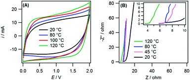
Fig. 4A and B show the cyclic voltammograms (CV) and Nyquist plots for the WiBS system at several temperatures ranging from 20 °C to 120 °C for the mass-balanced, 25% graphene electrode. Similar to the 21 m LiTFSI electrolyte, an increase in the capacitance was observed with increasing temperature, as seen in the ESI† (Fig. S4(A)), this corresponded to an increase in the energy density from 60.6 W h kg−1 (at 20 °C) to 78.9 W h kg−1 (at 120 °C). There was also a reduction in the solution and charge transfer resistance with increasing temperature. This is again due to a reduction in viscosity and an increase in the ionic conductivity and better access to the smallest micropores. However, unlike the 21 m LiTFSI electrolyte no significant reduction in the ESPW was observed with an increase in temperature. This is highlighted in Fig. S4(B) (ESI†), which shows improved capacitance retention during cycling (∼83%) at 110 °C using the LiTFSI/LiTFO electrolyte with 2 V as the upper limit.
As a result, the 21 m LiTFSI + 7 m LiTFO electrolyte has comparable energy density with commercial devices (∼75%) and can operate at higher temperatures (>100 °C). The capacitive performance and cyclability of the supercapacitors was unaffected by the heating and returned to previously measured values when tested at 20 °C (Fig. S5, ESI†). Therefore, no significant degradation of the electrode, electrolyte or cell components (e.g. aluminium current collector) occurred when the supercapacitor was operated at elevated temperatures.
In conclusion, we show the optimisation of a 25% graphene-containing AC electrode fabricated using industrial binder and current collectors with water-in-salt electrolytes. Using cell optimisation methods, the supercapacitor voltage window was maximised via mass balancing enabling each electrolyte to operate up to 2 V without any degradation. The mass balanced supercapacitors displayed gravimetric capacitances of ∼107 F g−1 and ∼109 F g−1 measured at room temperature at 0.2 A g−1 for 21 m LiTFSI and 21 m LiTFSI + 7 m LiTFO electrolytes, respectively. Additionally, we demonstrated that the electrolytes were capable of operating at temperatures of 100 °C (LiTFSI) and 120 °C (LiTFSI + LiTFO) with improved specific capacitance and energy density and reduced solution and charge transfer resistances. Furthermore, the high operating temperatures had no adverse effects on device performance when they were returned to room temperature. These findings demonstrate that water-in-salt electrolytes are excellent candidates for high temperature supercapacitor applications due to the compatibility with current commercial supercapacitor production methods and the inherent safety of the aqueous systems.
The authors acknowledge financial support from EPSRC (UK, grant reference EP/R023034/1).
Conflicts of interest
There are no conflicts to declare.References
- P. Simon and Y. Gogotsi, Nat. Mater., 2008, 7, 845–854 CrossRef CAS PubMed.
- L. L. Zhang and X. S. Zhao, Chem. Soc. Rev., 2009, 38, 2520–2531 RSC.
- E. Frackowiak, Phys. Chem. Chem. Phys., 2007, 9, 1774–1785 RSC.
- A. Burke, J. Power Sources, 2000, 91, 37–50 CrossRef CAS.
- J. R. Miller and A. F. Burke, Electrochem. Soc. Interface, 2008, 17, 53 CrossRef CAS.
- R. Kötz and M. Carlen, Electrochim. Acta, 2000, 45, 2483–2498 CrossRef.
- R. S. Borges, A. L. M. Reddy, M.-T. F. Rodrigues, H. Gullapalli, K. Balakrishnan, G. G. Silva and P. M. Ajayan, Sci. Rep., 2013, 3, 1–6 Search PubMed.
- T. Abdallah, D. Lemordant and B. Claude-Montigny, J. Power Sources, 2012, 201, 353–359 CrossRef CAS.
- L. Suo, O. Borodin, T. Gao, M. Olguin, J. Ho, X. Fan, C. Luo, C. Wang and K. Xu, Science, 2015, 350, 938–943 CrossRef CAS PubMed.
- L. Suo, O. Borodin, W. Sun, X. Fan, C. Yang, F. Wang, T. Gao, Z. Ma, M. Schroeder and A. von Cresce, Angew. Chem., 2016, 128, 7252–7257 CrossRef.
- X. Wu, Y. Xu, C. Zhang, D. P. Leonard, A. Markir, J. Lu and X. Ji, J. Am. Chem. Soc., 2019, 141, 6338–6344 CrossRef CAS PubMed.
- L. Suo, O. Borodin, Y. Wang, X. Rong, W. Sun, X. Fan, S. Xu, M. A. Schroeder, A. V. Cresce and F. Wang, Adv. Energy Mater., 2017, 7, 1701189 CrossRef.
- D. P. Leonard, Z. Wei, G. Chen, F. Du and X. Ji, ACS Energy Lett., 2018, 3, 373–374 CrossRef CAS.
- X. Bu, L. Su, Q. Dou, S. Lei and X. Yan, J. Mater. Chem. A, 2019, 7, 7541–7547 RSC.
- T. Liang, R. Hou, Q. Dou, H. Zhang and X. Yan, Adv. Funct. Mater., 2021, 31, 2006749 CrossRef CAS.
- G. Hasegawa, K. Kanamori, T. Kiyomura, H. Kurata, T. Abe and K. Nakanishi, Chem. Mater., 2016, 28, 3944–3950 CrossRef CAS.
- E. Frackowiak and F. Beguin, Carbon, 2001, 39, 937–950 CrossRef CAS.
- R.-S. Kühnel, D. Reber, A. Remhof, R. Figi, D. Bleiner and C. Battaglia, Chem. Commun., 2016, 52, 10435–10438 RSC.
- K. Mahankali, N. K. Thangavel, Y. Ding, S. K. Putatunda and L. M. R. Arava, Electrochim. Acta, 2019, 326, 134989 CrossRef CAS.
- M. A. Bissett, I. A. Kinloch and R. A. W. Dryfe, ACS Appl. Mater. Interfaces, 2015, 7, 17388–17398 CrossRef CAS PubMed.
- H. Jiang, P. S. Lee and C. Li, Energy Environ. Sci., 2013, 6, 41–53 RSC.
- E. Redondo, L. W. Le Fevre, R. Fields, R. Todd, A. J. Forsyth and R. A. W. Dryfe, Electrochim. Acta, 2020, 360, 136957 CrossRef CAS.
- L. W. Le Fevre, R. Fields, E. Redondo, R. Todd, A. J. Forsyth and R. A. W. Dryfe, J. Power Sources, 2019, 424, 52–60 CrossRef CAS.
- S. Vaquero, J. Palma, M. Anderson and R. Marcilla, Int. J. Electrochem. Sci., 2013, 8, 10293–10307 CAS.
- B. Andres, A.-C. Engström, N. Blomquist, S. Forsberg, C. Dahlström and H. Olin, PLoS One, 2016, 11, e0163146 CrossRef PubMed.
- J. C. Varela, K. Sankar, A. Hino, X. Lin, W. Chang, D. Coker and M. Grinstaff, Chem. Commun., 2018, 54, 5590–5593 RSC.
- A. Balducci, R. Dugas, P.-L. Taberna, P. Simon, D. Plee, M. Mastragostino and S. Passerini, J. Power Sources, 2007, 165, 922–927 CrossRef CAS.
- P. W. Ruch, D. Cericola, A. Foelske-Schmitz, R. Kötz and A. Wokaun, Electrochim. Acta, 2010, 55, 4412–4420 CrossRef CAS.
- T. Quan, E. Härk, Y. Xu, I. Ahmet, C. Höhn, S. Mei and Y. Lu, ACS Appl. Mater. Interfaces, 2021, 13, 3979–3990 CrossRef CAS PubMed.
- Y. Deng, H. Wang, K. Zhang, J. Shao, J. Qiu, J. Wu, Y. Wu and L. Yan, Nanoscale, 2021, 13, 3010–3018 RSC.
- L. Liu, Q. Dou, Y. Sun, Y. Lu, Q. Zhang, J. Meng, X. Zhang, S. Shi and X. Yan, J. Mater. Chem. A, 2019, 7, 20398–20404 RSC.
- X. Lu, R. J. Jiménez-Riobóo, D. Leech, M. C. Gutiérrez, M. L. Ferrer and F. Del Monte, ACS Appl. Mater. Interfaces, 2020, 12, 29181–29193 CAS.
Footnote |
| † Electronic supplementary information (ESI) available: Experimental setup and post high temperature measurement cycling. See DOI: 10.1039/d1cc01087e |
| This journal is © The Royal Society of Chemistry 2021 |


