 Open Access Article
A screen-printed three-electrode-type sticker device with an accurate liquid junction-type reference electrode†
Isao
Shitanda‡
 *ab,
Kaishi
Miyazaki‡
a,
Noya
Loew
a,
Ryosuke
Esaka§
a,
Yoshinao
Hoshi¶
a and
Masayuki
Itagaki
ab
aDepartment of Pure and Applied Chemistry, Faculty of Science and Technology, Tokyo University of Science, 2641 Yamazaki, Noda, Chiba 278-8510, Japan. E-mail: shitanda@rs.tus.ac.jp; Fax: +81 4 7123 9890; Tel: +81 4 7124 1501
bResearch Institute for Science and Technology, Tokyo University of Science, 2641 Yamazaki, Noda, Chiba 278-8510, Japan
First published on 24th February 2021
Abstract
We developed a novel sticker device that can convert any metal or alloy into the working electrode of a three-electrode system, enabling simple and accurate measurement. The sticker, containing a counter electrode and a stable and accurate liquid junction-type reference electrode, is attached to the metal or alloy; meanwhile the surface exposed from a hole in the device functions as the working electrode. This sticker device was fabricated by screen-printing. The polarization curve of the copper and tin-plated copper measured using the sticker device exhibited approximately the same behavior as that obtained for the conventional three-electrode system. The characteristics of various materials can be easily evaluated using this system by only dropping a small amount of solution.
Electrochemical measurement using a three-electrode system in an aqueous solution is widely used to conduct research on batteries, surface treatment, metal corrosion/corrosion protection, and fuel cells, among other fields, to analyze basic electrochemical reactions.
In a commonly used three-electrode measurement system, accurate and reproducible measurement is possible by correctly arranging independent working, counter, and reference electrodes at fixed positions. However, in recent years, printed electrochemical devices capable of integrating such electrodes on a single substrate have gained popularity because they enable easy electrochemical measurements. In particular, screen-printed electrodes having three electrodes are widely used in various fields, such as basic electrochemical measurement, environmental pollution research, biosensors, and electrochemical analysis.1–14 The devices fabricated by screen-printing can be mass-produced at low cost and exhibit good reproducibility.
In the aforementioned screen-printed sensors, carbon or gold is often employed as a working electrode, silver or carbon as a counter electrode, and silver/silver chloride as a reference electrode, mainly on an insulating plastic or ceramic substrate. Conventional screen-printed sensors, however, present issues with respect to the electrode materials that have to be determined in advance, and the material of the working electrode, which is particularly limited to carbon and silver as they can be converted into ink.
Additionally, the reference electrode commonly is a “pseudo-reference electrode”, prepared by printing a silver or silver/silver chloride layer.15–23 However, deviation of the reference potential due to fluctuation of the chloride ion concentration may result in significant problems pertaining to the accuracy of measurement in some cases.
To resolve this issue, we previously developed a full screen-printed liquid-junction-type reference electrode that exhibits long-term stability, instantaneous usability, and remarkable accuracy.24 The potential of this reference electrode did not fluctuate depending on the concentration of chloride ions in the measurement solution.
In this study, we developed a novel sticker device that can convert any metal or alloy into the working electrode of a three-electrode system using its unprecedented features. The device can be attached to the metal or alloy to be measured. It comprises a liquid-junction reference electrode,24 a counter electrode, and, as will be described in detail later, a hole in the sticker that is placed in a manner such that the object to be measured becomes the working electrode. It is expected that the corrosion and battery performance can be evaluated by simply sticking it on a substrate, such as a metal or an alloy, for which electrochemical evaluation is desired.
In this study, copper and tin-plated copper were used as the representative substrates. They are widely used in piping for absorption chillers and large air-conditioning equipment because of their excellent thermal conductivity and processability. However, depending on the composition of ions in the solution, such as chloride, sulfate, or bicarbonate ions, pitting corrosion may occur on the surface.25,26 We previously reported that it is possible to effectively and rapidly predict the occurrence of pitting corrosion for varying water quality, by determining the pitting potential from the polarization curves of copper and tin-plated copper using conventional three-electrode measurement.27 Therefore, in this study, aiming at application to a pitting prediction sensor using copper and tin-plated copper substrates, polarization curves were measured using the sticker device attached on the copper and tin-plated copper substrates.
Silver ink (SAP-40FL, Sanwa-Chemical Industrial Co., Ltd, Japan), isophorone (Fujifilm Wako Pure Chemical Corporation, Japan), poly(vinylidene difluoride) (PVdF, KF polymer #1300, Kureha, Japan), Triton X (Alfa Aesar, USA), silica gel (Aldrich, Japan), 1,3-dimethyl-3,4,5,6-tetrahydro-2(1H)-pyrimidinone (DMPU, 98.0% grade, Tokyo Chemical Industry Co., Ltd, Japan), KCl (99.5% grade, Fujifilm Wako Pure Chemical Corporation, Japan), and resist ink (S-40 C518, Taiyo Ink Co. Ltd, Japan) were used for the preparation of the sticker device. A silver/silver chloride ink used was prepared by mixing silver chloride with silver ink. The measurement solution was prepared by dissolving NaCl (99.5% grade, Fujifilm Wako Pure Chemical Corporation, Japan) in pure water (Purelab Option-R 7/15, ELGA Lab Water, Japan) to adjust the concentration to 10 ppm, 30 ppm, 100 ppm, and 300 ppm. Copper (Niraco, Japan) and tin-plated copper plates27 (tin plating thickness: 5.6 μm) were used as the substrates.
The manufacturing process of the sticker device is shown in Fig. S1 (ESI†). Polyethylene terephthalate (PET), with adhesive on one side (Nichieikako Co., Ltd), was used as the substrate for the sticker device. Initially, the counter electrode and first layer of the reference electrode were printed on the PET substrate using silver ink with a screen-printer (LS-150TV, Newlong Seimitsu Kogyo Co., Ltd), and dried at 150 °C for 30 min. The second layer of the reference electrode was then printed using silver/silver chloride ink and dried at 150 °C for 30 min.
Electrolyte ink was prepared by combining 1 g Triton X, 8 g DMPU, and 1 g PVdF in a stainless-steel container, and stirring the mixture at 80 °C for 12 h. Subsequently, 1 g silica gel and 4 g KCl were added and thoroughly mixed to form an ink using an ultrasonic homogenizer (PR-01, Thinky, Japan) first and then a revolving/rotating mixer (ARE-310, Thinky, Japan). The electrolyte ink was printed as the next layer of the reference electrode and dried at 180 °C for 30 min.
Liquid-junction ink was prepared by combining 1 g Triton X, 8 g isophorone, and 1 g PVdF in a stainless-steel container, and stirring the mixture at 80 °C for 12 h. Subsequently, 2 g silica gel was added, and mixed together to form an ink using a stirrer/defoamer. The liquid-junction ink was printed as the final layer of the reference electrode and dried at 180 °C for 30 min.
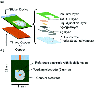
On top of the electrodes, an insulating layer was printed using resist ink and dried at 150 °C for 30 min. The sticker device was finalized by punching a 2 mm diameter hole in lieu of the working electrode. The laminar structure of the sticker device and the final electrode arrangement are shown in Fig. 1. The sticker device was attached to the metal to be measured in the electrochemical experiment. Before the sticker device was attached, the metals were polished with fine 1 μm alumina powder, degreased with methanol, and washed with pure water.
 | ||
| Fig. 1 Schematic illustrations of (a) laminated printing structure of the sticker device and (b) electrode arrangement of the sticker device. | ||
To evaluate the performance of the screen-printed reference electrode on the sticker device, open-circuit measurements were performed against a commercially available silver/silver chloride/saturated potassium chloride (Ag/AgCl/sat. KCl) reference electrode (SSE) using the set-up shown in Fig. S2a (ESI†).
Polarization curves were recorded using the set-up shown in Fig. S2b (ESI†). In this set-up, a reservoir made of silicone was placed on the device to accurately hold 1 mL of the solution in place.
To utilize the working electrode of the sticker device in conventional three-electrode measurements, the set-up in Fig. S2c (ESI†) was used. Here, a platinum wire was used as the counter electrode, and a commercial SSE as the reference electrode.
The sticker device attached to the copper plate was evaluated at a scan rate of 100 mV min−1 in 10 ppm NaCl on a large scale, and the results were compared to those obtained using the corresponding conventional three-electrode system. The device attached to the tin-plated copper was evaluated in 10 ppm, 30 ppm, 100 ppm, and 300 ppm NaCl on a small scale. Error bars were determined using the Student's t distribution at a 90% confidence level (n = 3).
The reference electrode of the sticker device is based on our ready-to-use, long-term, stable, printable reference electrode containing silica gel as the liquid junction.24 In this reference electrode, water permeates through a hydrophilic and porous silica gel liquid junction. The permeated water then dissolves potassium chloride in the electrolyte layer with silica gel as the support. As a result, the chloride ion concentration becomes saturated in the electrolyte layer. The potential exhibits a stable value, while the chloride ions maintain their saturation concentration.
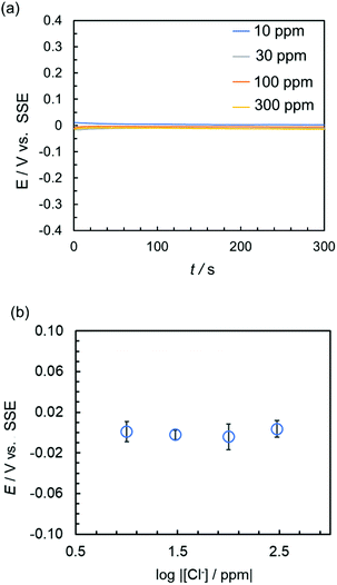
The performance of the reference electrode of the sticker device was evaluated by measuring its potential against a commercial SSE, in the presence of different concentrations of Cl− or 100 ppm of different anions (Fig. 2 and Fig. S3, ESI†). The potential of the reference electrode of the sticker device was stabilized approximately 60 s after immersion in an aqueous solution of NaCl (Fig. 2a) and remained stable over several hours (Fig. S3d, ESI†). A similar behavior was observed in the presence of other anions (Fig. S3a–c, ESI†).
Furthermore, the potential of the reference electrode of the device after 300 s was not affected by the chloride ion concentration, with an accuracy of approximately ±15 mV vs. SSE (Fig. 2b). This indicated that the sticker device can be used for accurate measurements in fresh water.
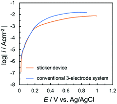
To evaluate the sticker device, the polarization curve of copper was measured using a 10 ppm NaCl solution, and compared to a corresponding measurement using a conventional three-electrode system (Fig. 3). In both polarization curves, the immersion potential was approximately 0.01 V. Furthermore, when the potential was scanned to the positive side, the current increased sharply. This was attributed to the dissolution current due to the general corrosion of copper. The behavior of the dissolution current was approximately the same in the case of the sticker device and conventional three-electrode system. This suggested that the corrosion behavior of metal substrates can be easily evaluated using this sticker device. The lower current value at more positive potentials obtained with the sticker device was attributed to the different convection and ion diffusion behaviors in the significantly different volumes used in the two types of measurement.
 | ||
| Fig. 3 Polarization curves of copper using the sticker device and the conventional three-electrode system in 10 ppm NaCl solution. | ||
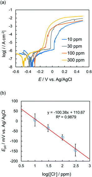
Subsequently, polarization curves of the tin-plated copper in different concentrations of NaCl were measured using the sticker device (Fig. 4). When the working electrode potential was scanned from the immersion potential in the positive direction, a rapid increase in the current due to the occurrence of pitting corrosion was confirmed. The onset of this current increase shifted toward more positive potentials with increasing chloride ion concentrations. The lowest current value of the pitting corrosion was between approximately 1 μA cm−2 and 10 μA cm−2. Thus, the potential at 10 μA cm−2 was defined as the pitting potential (Epit). Epit and the chloride ion concentration clearly showed a negative linear correlation (Fig. 4b). This behavior was similar to that obtained for the conventional three-electrode system.27
In conclusion, we succeeded in fabricating a sticker device with a liquid-junction-type reference electrode. Although a sticker device could, in principle, be fabricated with any printable reference electrode, our liquid-junction reference electrode is extremely accurate and comparable to conventional reference electrodes, and thus preferable. It was demonstrated that the polarization curve of the three-electrode system can be easily measured by simply attaching the sticker device to the substance to be measured and applying a drop of the measurement solution. By attaching this sticker device to a corrosion measurement object (for example, piping), there is a possibility that in situ electrochemical measurements can be performed without the need for processing the object of measurement. Moreover, this device can convert any conductive material into the working electrode of a three-electrode system. For example, gold and carbon are often used as electrode materials in chemical and biological sensors; however, printed gold and carbon often possess a high internal resistance. A sticker device could transform a low-resistance solid plate into an easy-to-use sensor chip platform. Furthermore, since this device can measure with a small amount of solution, it could also be possible to measure local electrochemical reactions while simultaneously observing the sample with a microscope.
Conflicts of interest
There are no conflicts to declare.References
- L. Manjakkal, K. Cvejin, J. Kulawika, K. Zaraska, D. Szwagierczak and R. P. Socha, Sens. Actuators, B, 2014, 204, 57, DOI:10.1016/j.snb.2014.07.067.
- B. P. Simon, J. Macanas, M. Munoz and E. Fabregas, Talanta, 2007, 71, 2102, DOI:10.1016/j.talanta.2006.09.022.
- G. Martinelli, M. C. Carotta, M. Ferroni, Y. Sadaoka and E. Traversa, Sens. Actuators, B, 1999, 55, 99, DOI:10.1016/S0925-4005(99)00054-4.
- A. E. Musa, F. J. Campo, N. Abramova, M. A. A. Lomillo, O. D. Renedo, M. J. A. Martinez, M. Brivio, D. Snakenborg, O. R. Geschke and J. P. Kutter, Electroanalysis, 2011, 23, 115, DOI:10.1002/elan.201000443.
- A. Rahman, P. Kumar, D. S. Park and Y. B. Shim, Sensors, 2008, 8, 118, DOI:10.3390/s8010118.
- A. Abellan-Llobregat, I. Jeerapan, A. Bandodkar, L. Vidal, A. Canals, J. Wang and E. Morallon, Biosens. Bioelectron., 2017, 91, 885, DOI:10.1016/j.bios.2017.01.058.
- H. Shuai and Y. Lei, Int. J. Electrochem. Sci., 2016, 11, 7430, DOI:10.20964/2016.09.38.
- I. Shitanda, S. Takamatsu, K. Watanabe and M. Itagaki, Electrochim. Acta, 2009, 54, 4933, DOI:10.1016/j.electacta.2009.04.005.
- I. Shitanda, A. Okumura, M. Itagaki, K. Watanabe and Y. Asano, Sens. Actuators, B, 2009, 139, 292, DOI:10.1016/j.snb.2009.03.027.
- J. Gonzalo-Ruiz, M. A. Alonso-Lomillo and F. J. Munoz, Biosens. Bioelectron., 2007, 22, 1517, DOI:10.1016/j.bios.2006.07.020.
- M. H. Shi, J. J. Xu, S. Zhang, B. H. Liu and J. L. Kong, Talanta, 2006, 68, 1089, DOI:10.1016/j.talanta.2005.07.007.
- K. C. Honeychurch and J. P. Hart, TrAC, Trends Anal. Chem., 2003, 22, 456, DOI:10.1016/S0165-9936(03)00703-9.
- P. Sarkar, I. E. Tothill, S. J. Setford and A. P. F. Turner, Analyst, 1999, 124, 865, 10.1039/a901404g.
- J. P. Hart and S. A. Wring, TrAC, Trends Anal. Chem., 1997, 16, 89, DOI:10.1016/S0165-9936(96)00097-0.
- D. Cicmil, S. Anastasova, A. Kavanagh, D. Diamond, U. Mattinen, J. Bobacka, A. Lewenstam and A. Radu, Electroanalysis, 2011, 23, 1881, DOI:10.1002/elan.201100137.
- J. Hu, K. T. Ho, X. U. Zou, W. H. Smyrl, A. Stein and P. Buhlmann, Anal. Chem., 2015, 87, 2981, DOI:10.1021/ac504556s.
- P. J. Kinlen, J. E. Heider and D. E. Hubbard, Sens. Actuators, B, 1994, 22, 13, DOI:10.1016/0925-4005(94)01254-7.
- W. J. Lan, E. J. Maxwell, C. Parolo, D. K. Bwambok, A. B. Subramaniam and G. M. Whitesides, Lab Chip, 2013, 13, 4103, 10.1039/c3lc50771h.
- M. A. Nolan, S. H. Tan and S. P. Kounaves, Anal. Chem., 1997, 69, 1244, DOI:10.1021/ac961020f.
- F. X. Rius-Ruiz, D. Bejarano-Nosas, P. Blondeau, J. Riu and F. X. Rius, Anal. Chem., 2011, 83, 5783, DOI:10.1021/ac200627h.
- M. Sophocleous and J. K. Atkinson, Sens. Actuators, A, 2017, 267, 106, DOI:10.1016/j.sna.2017.10.013.
- Y. Xia, J. H. Cho, B. Paulsen, C. D. Frisbie and M. J. Renn, Appl. Phys. Lett., 2009, 94, 3, DOI:10.1063/1.3058694.
- C. Zuliani, G. Matzeu and D. Diamond, Talanta, 2014, 125, 58, DOI:10.1016/j.talanta.2014.02.018.
- M. Komoda, I. Shitanda, Y. Hoshi and M. Itagaki, Electrochemistry, 2018, 87, 65–67, DOI:10.5796/electrochemistry.18-00075.
- S. Yamauchi and S. Sato, Boshoku Gijutsu, 1981, 30, 469, DOI:10.3323/jcorr1974.30.8_469.
- M. Sakai and N. Matsumoto, ZAKAEP, 2011, 60, 126, DOI:10.3323/jcorr.60.126.
- I. Shitanda, K. Kumagai, C. Takami, Y. Hoshi and M. Itagaki, Electrochemistry, 2021, 89, 54, DOI:10.5796/electrochemistry.20-00135.
Footnotes |
| † Electronic supplementary information (ESI) available. See DOI: 10.1039/d1cc00850a |
| ‡ I. S. and K. M. are equal contributors. |
| § Present address: Faculty of Pure and Applied Sciences, University of Tsukuba, 1-1-1 Tennodai, Tsukuba, Ibaraki, 305-8573, Japan. |
| ¶ Present address: Department of Physical Science and Engineering, Graduate School of Engineering, Nagoya Institute of Technology, Gokiso-cho, Showa-ku, Nagoya, 466-8555, Japan. |
| This journal is © The Royal Society of Chemistry 2021 |


