
 Open Access Article
 This Open Access Article is licensed under a Creative Commons Attribution-Non Commercial 3.0 Unported Licence
Intermetallic Fe6Ge5 formation and decay of a core–shell structure during the oxygen evolution reaction†
J. Niklas
Hausmann
a,
Roman A.
Khalaniya
 b,
Chittaranjan
Das
c,
Ina
Remy-Speckmann
a,
Stefan
Berendts
a,
Andrei V.
Shevelkov
b,
Matthias
Driess
*a and
Prashanth W.
Menezes
*a
b,
Chittaranjan
Das
c,
Ina
Remy-Speckmann
a,
Stefan
Berendts
a,
Andrei V.
Shevelkov
b,
Matthias
Driess
*a and
Prashanth W.
Menezes
*a
aDepartment of Chemistry, Technische Universität Berlin, Strasse des 17, Juni 135, Sekr. C2, Berlin 10623, Germany. E-mail: matthias.driess@tu-berlin.de; prashanth.menezes@mailbox.tu-berlin.de
bDepartment of Chemistry, Lomonosov Moscow State University, Moscow 119991, Russia
cKarlsruhe Institute of Technology (KIT), Institute for Applied Materials (IAM-ESS), Hermann-von-Helmholtz-Platz 1, Eggenstein-Leopoldshafen D-76344, Germany
First published on 22nd January 2021
Abstract
Herein, we report on intermetallic iron germanide (Fe6Ge5) as a novel oxygen evolution reaction (OER) precatalyst with a Tafel slope of 32 mV dec−1 and an overpotential of 272 mV at 100 mA cm−2 in alkaline media. Furthermore, we uncover the in situ formation of a core–shell like structure that slowly collapses under OER conditions.
The kinetically demanding oxygen evolution reaction (OER) is responsible for most of the efficiency loss in electrocatalytic water splitting.1 To overcome this disadvantage, a vast amount of OER (pre)catalysts based on abundant Fe, Co, and Ni have been investigated.1,2 Various kinds of materials with these three metals have been investigated for their OER properties, including oxides, chalcogenides, pnictides, carbides, borides, borates, phosphates, borophosphates, and intermetallics.1–5 Even though, at least at their surface, most of these compounds transform to layered (oxy)hydroxides under alkaline OER conditions, it has been shown that the nature of the non-OER active elements and the structure of the precatalyst influence the properties of the final catalyst.5–7 Such during OER formed catalysts have often shown high activities due to a remaining conductive core, an increased surface area, more exposed active sites caused by leaching of an element, and bulk instead of near-surface activity.5,6,8 In this regard, the exploration of novel precatalysts with exceptional structural characteristics could pave the way to superior OER catalysts. A promising and comparably unexplored class is intermetallics. In contrast to alloys, they possess ordered, particular structures and stoichiometries as well as a peculiar bonding situation.9 Furthermore, they contain conducting electrons together with a chance of self-supported corrosion during OER electrocatalysis.10 Herein, we report on the first iron-based OER catalyst containing germanium, intermetallic Fe6Ge5, and uncover its structural transformation during the OER.11,12
Intermetallic Fe6Ge5 was synthesized using a high-temperature annealing method (details in the ESI†). It crystallises in its own structure derived from the B8 type (Fig. 1a and Fig. S1, ESI†). The crystal structure consists of a dense packing of Fe and Ge atoms and is built up by polyhedra of five different Fe atoms forming square pyramids, distorted octahedra and pentagonal prisms with Ge atoms.13,14
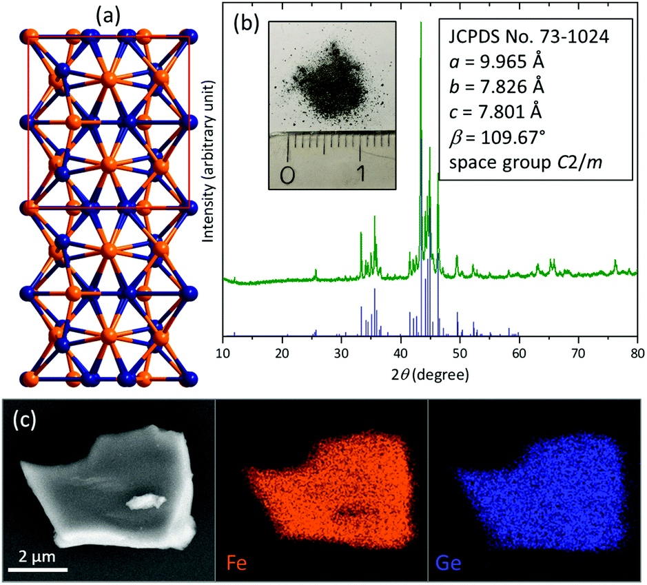 | ||
| Fig. 1 (a) Depiction of the Fe6Ge5 structure along [100] (Fe orange, Ge blue). (b) pXRD of the pristine Fe6Ge5 powder and image of the powder with a cm scale. The blue bars indicate the position and intensity of the reported reflections taken from the JCPDS database. (c) SEM/EDX mapping of a Fe6Ge5 particle. | ||
The powder X-ray diffraction (pXRD) pattern reveals the formation of pure Fe6Ge5 (Fig. 1b). Scanning electron microscopy (SEM) images show irregularly shaped particles with a size of 0.5–10 μm (Fig. S2, ESI†). SEM energy dispersive X-ray (EDX) mapping uncovers a homogeneous distribution of Fe and Ge (Fig. 1c) and the corresponding EDX spectrum does not contain any impurity peaks (Fig. S3, ESI†) and confirms the Fe![[thin space (1/6-em)]](https://www.rsc.org/images/entities/char_2009.gif) :Ge ratio of 6:5. After grinding, transmission electron microscopy (TEM) was conducted (Fig. S4, ESI†). The high-resolution image, the selected area diffraction pattern, and the EDX spectrum (Fig. S5, ESI†) confirm the presence of a pure, crystalline Fe6Ge5 phase. The Fe 2p X-ray photoelectron spectrum (XPS, Fig. S6a, ESI†) reveals the presence of Fe0 consistent with the intermetallic nature of Fe6Ge5.15 Additionally, also a FeII surface species is observed originating from surface passivation in air, which is typical for intermetallic species.4,16 In agreement with this observation, the Ge 3d XPS spectrum shows the presence of Ge0 together with oxidised GeII and GeIII species (Fig. S6b, ESI†).17
:Ge ratio of 6:5. After grinding, transmission electron microscopy (TEM) was conducted (Fig. S4, ESI†). The high-resolution image, the selected area diffraction pattern, and the EDX spectrum (Fig. S5, ESI†) confirm the presence of a pure, crystalline Fe6Ge5 phase. The Fe 2p X-ray photoelectron spectrum (XPS, Fig. S6a, ESI†) reveals the presence of Fe0 consistent with the intermetallic nature of Fe6Ge5.15 Additionally, also a FeII surface species is observed originating from surface passivation in air, which is typical for intermetallic species.4,16 In agreement with this observation, the Ge 3d XPS spectrum shows the presence of Ge0 together with oxidised GeII and GeIII species (Fig. S6b, ESI†).17
For OER investigations of Fe6Ge5, we deposited 0.4 mg cm−2 on fluorine doped tin oxide (FTO) glass plates using a binder-free method (electrophoretic deposition (EPD), see ESI† for details and Fig. S7 and S8 for SEM/EDX data of the thin film). The obtained system, Fe6Ge5/FTO, was analysed by linear scan voltammetry (LSV, scan rate 1 mV s−1, Fig. 2a) together with the reference materials Fe, Fe(OH)3, FeOOH, and Fe2O3 (same loading and deposition method).4 Fe6Ge5/FTO yielded a current density (i) of 10 mA cm−2 at an overpotential (η) of 420 mV, whereas the second most active material, Fe/FTO, required over 70 mV more to reach the same i.
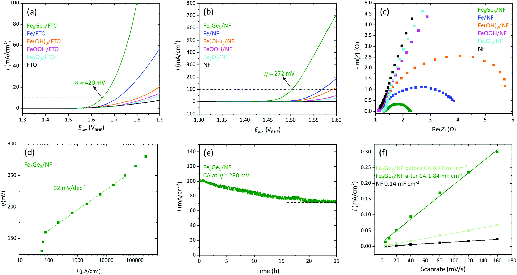 | ||
| Fig. 2 Electrochemical properties of Fe6Ge5 and other iron-based reference materials. (a) LSV (1 mV s−1) on FTO. (b) LSV (1 mV s−1) on NF. (c) Nyquist plot. (d) Steady state Tafel slope of Fe6Ge5. (e) CA measurement of Fe6Ge5. (f) Cdl determination of pristine NF and Fe6Ge5 before and after the CA measurement shown in (e). | ||
Motivated by this result, we deposited 1 mg cm−2 of Fe6Ge5 on highly conducting, 3D porous nickel foam (NF, Fig. S9 and S10 for SEM/EDX data, ESI†). The Fe6Ge5/NF yielded 10 mA cm−2 and 100 mA cm−2 at η values of 221 mV and 272 mV, respectively (Fig. 2b). The η10/100 required for the best iron based reference material is again 60–70 mV larger confirming the trend observed on FTO. Furthermore, we loaded various Ni-, Co-, and NiFe based catalysts with the same mass loading by EPD on NF and performed LSVs.6 Again, Fe6Ge5 shows the best activity (Fig. S11a, see Table S1 for η10 of state of the art catalysts, ESI†). The OER faradaic efficiency of Fe6Ge5 was determined to be 97% (Fig. S12, ESI†).
Inspired by the high activity of Fe6Ge5/NF, we performed further electrocatalytic investigations. Electrochemical impedance spectroscopy (EIS) at η = 270 mV of the iron-based materials revealed that Fe6Ge5 has the lowest charge-transfer resistance (Rct, Fig. 2c) consistent with the activity trend from the LSVs. Steady state Tafel data (Fig. 2d) disclose a wide kinetically controlled region (from 0.1 to 100 mA cm−2) with a slope of merely 32 mV dec−1 indicating excellent OER kinetics and mass transport properties of the system (see Fig. S11b for Tafel slopes of the Fe reference materials, ESI†). A chronoamperometry (CA) measurement at η = 280 mV yields initially 100 mA cm−2 (Fig. 2e). However, in the first 20 h, i decreases by 25% to 75 mA cm−2. Nevertheless, after this initial deactivation, i remains stable. By cycling in a potential region without a faradaic process (Fig. S13, ESI†), we determined the double layer capacitance (Cdl) before and after the OER reaction (Fig. 2f). This comparison uncovers that the Cdl increases by four times during the OER process. Such a strong change indicates that at least the surface of the material is transformed.
To understand the structural transformation of Fe6Ge5, we performed several analytical methods after 1 h at 10 mA cm−2 (Fig. S14, ESI†). The pXRD pattern (Fig. S15, ESI†) contains the characteristic reflections of the Fe6Ge5 phase and no new, additional peaks indicating that the Fe6Ge5 phase is still intact and that the newly formed phase is non-crystalline. SEM images show that the morphology of the particles did barely change (Fig. S16, ESI†). SEM/EDX mapping reveals a homogeneous distribution of Fe and Ge; however, the relative Ge content is 15% lower than in the pristine material (Fig. S16 and S17, ESI†).
TEM images show a porous material on the surface of the particles (Fig. 3a and b). And a SAED taken from such a surface region contains only two diffuse diffraction rings consistent with randomly distributed short-range ordered iron oxyhydroxide phases such as 2 line ferrihydrite and layered phases with edge sharing [MO6] octahedra (Fig. 3c).6,18 EDX data of the same area discloses a substantial incorporation of K and a Fe to O ratio of 1 to 2 while almost no Ge was left (Fig. 3c and Fig. S18 top, ESI†). A TEM SAED taken from the centre of the same particle contains reflections that can be assigned to a highly crystalline Fe6Ge5 phase (Fig. 3d). Furthermore, EDX reveals an only 15% decreased Ge content and a slight inclusion of K and O (Fig. 3d and Fig. S18, ESI,† bottom).
 | ||
| Fig. 3 TEM and XPS characterisation of Fe6Ge5 after 1 h at 10 mA cm−2. (a) TEM image of a Fe6Ge5 particle. At point 1 and 2, EDX and SAED data were collected. (b) High resolution TEM image. (c) SAED pattern and elemental ratio from EDX taken at point 1 in image a. (d) SAED pattern and elemental ratio from EDX taken at point 2 in image a. The large white circle corresponds to a lattice distance of 2.10 Å (fitting to the lattice plan with the miller index 023 of Fe6Ge5), the small triangle to a distance of 1.93 Å (040), the small square to a distance of 1.60 Å (−603 or −531 or −424), and the small circle to a distance of 1.54 Å (−441). (e–g) Fe 2p, Ge 3d and O 1s XPS spectra. | ||
XPS reveals more information about the in situ formed surface structure. In the deconvoluted 2p Fe spectrum, a small, residual amount of Fe0 is present while the major oxidation states are FeII and FeIII (Fig. 3e).15 Also, in the 3d Ge spectrum, a minor amount of residual Ge0 can be found but GeIII and GeIV are the dominant species (Fig. 3f).17 The deconvoluted O 1s spectrum contains three peaks (Fig. 3g). Two peaks are consistent with reported iron oxyhydroxide phases and can be assigned to iron oxide (529.6 eV) and iron hydroxide (531.1 eV), respectively.18–20 The hydroxide peak also overlaps with the Ge2IIIO3 and the peak at 532.5 eV is in accordance with GeIVO2.17
To this point, the Fe6Ge5 characterisation uncovers a highly active OER catalyst consisting of a conductive Fe6Ge5 core and an in situ formed amorphous shell. The stoichiometry of the newly formed shell is KxFeO2Hy. Structurally, the shell shows diffraction and XPS data consistent with randomly distributed short-range ordered layered oxyhydroxide structures or 2 line ferrihydrate.6,18 Such structures are typical for under OER conditions formed phases from an Fe containing precursor.7,8,16,21 The arguments for the superior activity of the Fe6Ge5 system compared to that of the Fe/Ni/Co-based reference materials are: (i) a high porosity which probably enables the electrolyte to penetrate the shell and leads to more active iron sites to participate in the OER process and a higher surface area, (ii) more edge iron sites and defects due to the disordered amorphous structure, and (iii) the presence of a conductive Fe6Ge5 core facilitating electron transport to the active sites.5,7,22
However, when such core–shell like structures are formed, it is important to investigate whether they remain or slowly the entire particle transforms.16,23 The long-term CA measurement (Fig. 2e) shows that, after the first hour, a continuous deactivation takes place within the next 20 h. The reason for that may be a further transformation of the structure. To investigate this, we performed SEM/EDX and XPS investigations after the 25 h CA measurement (Fig. S19–S21, ESI†). We find a barely altered morphology, but the Ge content decreased by 60%. The XPS data are to a large extent consistent with the one after 1 h OER, but barely show signals for Fe0 and Ge0 above the noise level. Thus, the conducting Fe6Ge5 core is constantly shrinking. In such a system, the OER reaction could take place either at the core–shell interface or at the near surface area of the particle (particle–electrolyte interface). In the first scenario, the mass transport limitation will increase with a shrinking core due to a larger iron oxyhydroxide shell that the electrolyte/hydroxide must penetrate until it reaches the reaction zone. In the second scenario, the limitation will arise from a longer distance that the electrons must travel through the poorly conducting iron oxyhydroxide until they reach the reaction zone. It is likely that a mixture of both scenarios transpires and leads to the deactivation of the Fe6Ge5 system.
The question that follows is: what are the criteria that make a core–shell structure stable? For the transformation of the core, it must be in contact with the electrolyte and electrically wired to the anode. The first condition is not given if the formed iron oxyhydroxide is not penetrable by the electrolyte resulting in a stable core–shell structure.23 The electrolyte penetrability of the shell will be determined by its porosity which will be inter alia a function of the leaching species. From a rational point of view, large leaching species should preferably lead to porosity. The volume of germanium calculated from its van der Waals radius is large (39 Å3) compared to other leaching elements in well-known OER precatalysts such as carbon (21 Å3), phosphorus (24 Å3), sulphur (24 Å3), or selenium (29 Å3).24 Note here that in solutions the nature of these leaching species is highly oxidised as can be seen in their Pourbaix diagrams (e.g. for germanium GeO32− should be present).7,25 Nevertheless, the void that they leave in the structure depends on the size of the original precatalyst species and not the oxidised one in solutions. Thus, the larger volume of germanium could be the reason why the in situ formed shell is electrolyte penetrable and does not protect the inner core. The fact that the transformation takes a comparably large amount of time under a rather high current density is caused by the large particle size of the utilized Fe6Ge5.
In conclusion, our work does not only present a detailed electrocatalytic analysis of a new, intermetallic compound but also evidences that core–shell structures can be metastable on a pathway to full precatalyst transformation.
We acknowledge the Einstein Center of Catalysis (EC2) and the Deutsche Forschungsgemeinschaft (DFG, German Research Foundation) under Germanys Excellence Strategy – EXC 2008/1 – 390540038 – UniSysCat. C. D. acknowledges the Karlsruhe Nano Micro Facility (KNMF, http://www.knmf.kit.edu), a Helmholtz research infrastructure at Karlsruhe Institute of Technology (KIT, http://www.kit.edu).
Conflicts of interest
There are no conflicts to declare.Notes and references
- N.-T. Suen, S.-F. Hung, Q. Quan, N. Zhang, Y.-J. Xu and H. M. Chen, Chem. Soc. Rev., 2017, 46, 337–365 RSC.
- J. Masa and W. Schuhmann, ChemCatChem, 2019, 11, 5842–5854 CrossRef CAS.
- P. W. Menezes, A. Indra, I. Zaharieva, C. Walter, S. Loos, S. Hoffmann, R. Schlögl, H. Dau and M. Driess, Energy Environ. Sci., 2019, 12, 988–999 RSC.
- B. Chakraborty, R. Beltrán-Suito, J. N. Hausmann, S. Garai, M. Driess and P. W. Menezes, Adv. Energy Mater., 2020, 10, 2001377 CrossRef CAS.
- B. R. Wygant, K. Kawashima and C. B. Mullins, ACS Energy Lett., 2018, 3, 2956–2966 CrossRef CAS.
- J. N. Hausmann, S. Mebs, K. Laun, I. Zebger, H. Dau, P. W. Menezes and M. Driess, Energy Environ. Sci., 2020, 13, 3607–3619 RSC.
- W. Li, D. Xiong, X. Gao and L. Liu, Chem. Commun., 2019, 55, 8744–8763 RSC.
- Q. He, H. Xie, Z. U. Rehman, C. Wang, P. Wan, H. Jiang, W. Chu and L. Song, ACS Energy Lett., 2018, 3, 861–868 CrossRef CAS.
- M. Armbrüster, R. Schlögl and Y. Grin, Sci. Technol. Adv. Mater., 2014, 15, 034803 CrossRef.
- N. Cinca, C. R. C. Lima and J. M. Guilemany, J. Mater. Res. Technol., 2013, 2, 75–86 CrossRef CAS.
- Z. Xu, W. Li, X. Wang, B. Wang, Z. Shi, C. Dong, S. Yan and Z. Zou, ACS Appl. Mater. Interfaces, 2018, 10, 30357–30366 CrossRef CAS.
- P. W. Menezes, S. Yao, R. Beltrán-Suito, J. N. Hausmann, P. V. Menezes and M. Driess, Angew. Chem., Int. Ed., 2020 DOI:10.1002/anie.202014331.
- A. Larsson, S. Furuseth and R. Withers, J. Solid State Chem., 1998, 141, 199–204 CrossRef CAS.
- B. Malaman, M. J. Phillippe, B. Roques, A. Courtois and J. Protas, Acta Crystallogr., Sect. B: Struct. Crystallogr. Cryst. Chem., 1974, 30, 2081–2087 CrossRef.
- M. C. Biesinger, B. P. Payne, A. P. Grosvenor, L. W. M. Lau, A. R. Gerson and R. S. C. Smart, Appl. Surf. Sci., 2011, 257, 2717–2730 CrossRef CAS.
- P. W. Menezes, C. Walter, J. N. Hausmann, R. Beltrán-Suito, C. Schlesiger, S. Praetz, V. Y. Verchenko, A. V. Shevelkov and M. Driess, Angew. Chem., Int. Ed., 2019, 58, 16569–16574 CrossRef CAS.
- Q. Lu, Y. Mu, J. Roberts, M. Althobaiti, V. Dhanak, J. Wu, C. Zhao, C. Zhao, Q. Zhang, L. Yang, I. Mitrovic, S. Taylor and P. Chalker, Materials, 2015, 8, 8169–8182 CrossRef CAS.
- J. N. Hausmann, E. M. Heppke, R. Beltrán-Suito, J. Schmidt, M. Mühlbauer, M. Lerch, P. W. Menezes and M. Driess, ChemCatChem, 2020, 12, 1161–1168 CrossRef CAS.
- H. Abdel-Samad and P. R. Watson, Appl. Surf. Sci., 1997, 108, 371–377 CrossRef CAS.
- B.-S. Zhu, Y. Jia, Z. Jin, B. Sun, T. Luo, L.-T. Kong and J.-H. Liu, RSC Adv., 2015, 5, 84389–84397 RSC.
- C. Feng, M. B. Faheem, J. Fu, Y. Xiao, C. Li and Y. Li, ACS Catal., 2020, 10, 4019–4047 CrossRef CAS.
- S. Anantharaj and S. Noda, Small, 2020, 16, 1905779 CrossRef CAS.
- P. Wilde, S. Dieckhöfer, T. Quast, W. Xiang, A. Bhatt, Y. Chen, S. Seisel, S. Barwe, C. Andronescu, T. Li, W. Schuhmann and J. Masa, ACS Appl. Energy Mater., 2020, 3, 2304–2309 CrossRef CAS.
- J. R. Rumble, CRC Handbook of Chemistry and Physics, CRC Press, 100th edn, 2019 Search PubMed.
- D. G. Brookins, Eh-pH Diagrams for Geochemistry, Springer-Verlag, Berlin Heidelberg, 1st edn, 1988 Search PubMed.
Footnote |
| † Electronic supplementary information (ESI) available. See DOI: 10.1039/d0cc08035g |
| This journal is © The Royal Society of Chemistry 2021 |