
 Open Access Article
 This Open Access Article is licensed under a
 Creative Commons Attribution 3.0 Unported Licence
CoMn phosphide encapsulated in nitrogen-doped graphene for electrocatalytic hydrogen evolution over a broad pH range†
Jingjing
Liu
a,
Wenyao
Li
 *a,
Zhe
Cui
b,
Jiaojiao
Li
a,
Fang
Yang
*a,
Liping
Huang
a,
Caiyu
Ma
a and
Min
Zeng
*c
*a,
Zhe
Cui
b,
Jiaojiao
Li
a,
Fang
Yang
*a,
Liping
Huang
a,
Caiyu
Ma
a and
Min
Zeng
*c
aSchool of Materials Engineering, Shanghai University of Engineering Science, Shanghai 201620, China. E-mail: liwenyao314@gmail.com; yfang@sues.edu.cn
bState Key Laboratory for Modification of Chemical Fibers and Polymer Materials College of Materials Science and Engineering, Donghua University, Shanghai 201620, China
cKey Laboratory of Thin Film and Microfabrication (Ministry of Education), Department of Micro/Nano Electronics, School of Electronic Information and Electrical Engineering, Shanghai Jiao Tong University, 800 Dong Chuan Road, Shanghai 200240, China. E-mail: minzeng@sjtu.edu.cn
First published on 22nd January 2021
Abstract
CoMn phosphide encapsulated in a nitrogen-doped graphene core–shell structure was successfully prepared with Prussian Blue complexes as the precursor and P atom doping at a high temperature. The core–shell heterostructure demonstrates an impressive catalytic performance of hydrogen evolution reaction over a broad pH range, i.e., the overpotentials reach 159, 190 and 279 mV at a current density of 20 mA cm−2 in the conditions of pH = 0, 14 and 7, and maintains excellent stability.
Nowadays, with the excessive consumption of fossil fuels, environmental pollution and energy shortage are becoming more and more serious.1 Therefore, it is necessary to develop new alternative or renewable energy sources to alleviate and fundamentally solve these problems.2,3 As a kind of sustainable and renewable energy with abundance and zero carbon emission, hydrogen has become an ideal alternative to fossil fuels. Electrochemical overall water splitting is considered to be an efficient and clean method.4,5 However, the low kinetics of the catalysts and the high cost of precious metals (Pt, Pd) and their alloys hinder the development and application of electrolytic water splitting for hydrogen at a large scale.6,7 Moreover, most hydrogen evolution reaction (HER) active catalysts only perform well under a single condition.8,9 Therefore, it is urgent to develop catalysts with abundant resources, low cost, high efficiency, and stability, suitable for a wide range of pH conditions to replace platinum group precious metals to realize the industrialization development of hydrogen production.
Among many promising non-noble metal catalysts, Co-based Prussian Blue (PB) analogues have received extensive attention because of their low overpotential and excellent electrocatalytic activity as HER catalysts.10,11 For instance, Ma's group synthesized a porous hollow carbon microsphere PB-Co/Co-N-PHCS nanocomposite and performed HER studies under alkaline conditions, showing good catalytic activity.12 However, its application under a wide range of pH conditions still needs improvement. Meanwhile, due to the poor conductivity of cobalt-base PB materials, self-aggregation is easy to occur in the reaction process, which limits their practical application as electrolytic water-splitting catalysts. With conductive porous carbon and a multi-layer graphene-coated core–shell structure, the metal core encapsulated in multi-layer graphene avoids the loss of metal ions in the reaction process, and improves the utilization rate of electrons between metal ions and multi-layer graphene, and then facilitates the transmission rate.13,14 Du et al. designed and synthesized the core–shell FeCo@NG/NCNT, which presented excellent mass transfer capability and charge transfer properties, which can be effectively applied for the HER and oxygen evolution reaction (OER).15 Besides, the introduction of N and P elements into the heterogeneous structure can further adjust the electronic properties of the material and generate more active sites, which further improves the catalytic activity.16,17
Herein, we have synthesized CoMn phosphide encapsulated in a nitrogen-doped graphene core–shell structure by the combination of the coprecipitation method and annealing treatment at high temperature. Comparing the HER properties of graphene-coated composites before and after P doping in a wide pH environment, it was found that P doped CoMn@NG formed more active sites and showed better electrocatalytic activity of hydrogen evolution due to the P atoms entering the CoMn bimetal core. The P dopants with low electronegativity reduce the activation energy barrier during the reaction and generate more active sites.18 As a result, CoMn-P@NG has strong electron transport capacity and electrocatalytic activity in a wide pH environment. The results have demonstrated that CoMn-P@NG can be used as a high-performance catalyst for the hydrogen evolution reaction.
As schematically illustrated in Fig. 1a, the CoMn@NG was synthesized through the annealing of PB-CoMn precursor, then using sodium hypophosphate as a phosphorus source doped into CoMn@NG to form CoMn-P@NG. From the XRD patterns in Fig. 1b, the diffraction peaks of CoMn@NG at 21.70° and 31.34° correspond to the (102) and (004) planes of CoO (marked with ♦, JCPDS No. 89-2803). The peaks at 11.72°, 18.06° 18.81°, 20.52°, 23.46° and 25.43° correspond to the (111), (120), (022), (114), (222) and (223) planes of Co2Mn3O8 (marked with &, JCPDS No. 30-0446), respectively. The diffraction peaks of CoMn-P@NG at 10.47°, 14.61°, 16.59°, 17.15°, 21.03°, 30.46° 36.25° and 37.75° belong to the (101), (011), (111), (201), (202), (312) (105) and (015) planes of Co0.3Mn0.7P (marked with #, JCPDS No. 65-3921), indicating the success of P doping. The diffraction peaks at 17.65°, 19.04°, 23.41°, 25.11° and 32.88° belong to the (201), (202), (103), (212), and (303) planes of Co1.94P (marked with *, JCPDS No. 89-3032). These peaks demonstrate that part of the Co1.94P compounds exist in the CoMn-P@NG. The Raman spectra of CoMn-P@NG and CoMn@NG in Fig. 1c show two characteristic peaks in the range of 1292–1615 cm−1, corresponding to the D and G bands of graphene.19 The defect density is proportional to the value of ID/IG.20 The ID/IG values of CoMn-P@NG and CoMn@NG are 1.15 and 1.06, respectively, which indicates that the defect degree of CoMn-P@NG was more than CoMn@NG after phosphorus doping. These defects of the structure provide more active sites, which could make the electrochemical performance better.
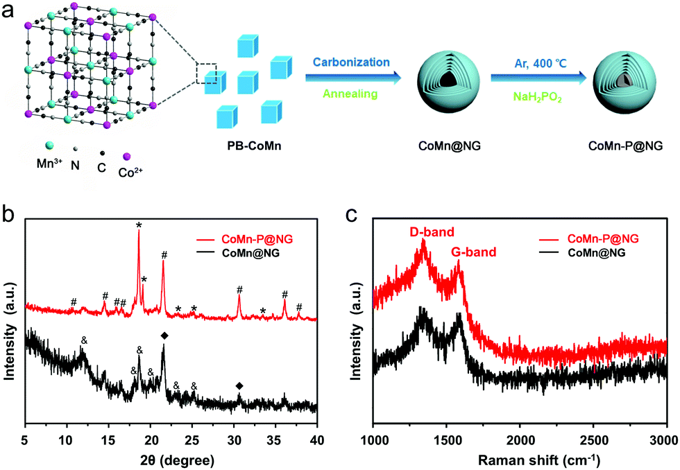 | ||
| Fig. 1 (a) Schematic illustration of the synthetic process of CoMn-P@NG. (b) XRD patterns and (c) Raman spectra of CoMn@NG and CoMn-P@NG. | ||
The morphology of CoMn-P@NG is nanocubes with a length of about 200 nm (Fig. 2a–c). Besides, the morphology of CoMn@NG (Fig. S1, ESI†) is similar to that of CoMn-P@NG. As shown in Fig. 2d, the TEM image of CoMn-P@NG further testifies that the nanocubes are composed of nanoparticles. As displayed in Fig. 2e, the enlarged TEM image shows that these nanoparticles were core–shell structures. Fig. S2 (ESI†) also shows that the CoMn@NG is a core–shell structure. The HRTEM image of Fig. 2f further demonstrates the core–shell heterostructure for CoMn-P@NG. The darker part inside was the bimetallic core, where the lattice fringe with the plane spacing of 0.23 and 0.26 nm belongs to the (201) plane of Co0.3Mn0.7P and (201) plane of Co1.94P. The brighter part of the outer layer is the graphene layer, which agrees with the above Raman analysis, indicating the formation of multiple layers of graphene during the material synthesis. The elemental mapping images indicate that Mn, Co and P elements are uniformly distributed in the core while C and N elements uniformly exist in the shell (Fig. 2g–l). Importantly, the P is only distributed in the core place of the heterostructure where the CoMn bimetals exist. These results have given a sufficient indication that the P element is successfully doped into the core part of the CoMn-P@NG nanoparticles.
 | ||
| Fig. 2 (a–c) SEM, (d) TEM, (e and f) HRTEM, (g) STEM and (h–l) the corresponding EDS elemental mapping images of CoMn-P@NG. | ||
In order to better understand the elemental composition and surface electron valence of the material, the CoMn-P@NG was analyzed in detail by XPS. Fig. 3a shows the full XPS spectrum of CoMn-P@NG. The corresponding high-resolution spectra are analyzed in detail. Four peaks were found in the high-resolution spectrum of Co element (Fig. 3b), and the two strong peaks located at 777.8 and 796.8 eV are attributed to the phosphating of the Co atom, forming a Co–P bond. The two weak peaks located at 784.9 and 802.5 eV correspond to Co 2p3/2 and Co 2p1/2, indicating that the valence state of Co is +2 valence.21 The existence of the Co–P bond could increase the electron transfer rate in the electrochemical reaction process, thus promoting the electrochemical activity of the catalyst.22,23 The high-resolution XPS spectrum of Mn element is shown in Fig. 3c, which also can be divided into four peaks: Mn 2p3/2 (641.2 eV), Mn3+ (645.4 eV), Mn2+ (649.6 eV) and Mn 2p1/2 (653.3 eV), proving the existence of CoMn bimetals in the CoMn-P@NG structure and the coexistence as miscible phases.24 There is a strong peak of C![[double bond, length as m-dash]](https://www.rsc.org/images/entities/char_e001.gif) C (284.7 eV) and three weak peaks of C–N (285.7 eV), C–O (286.4 eV), and CO (288.4 eV) in the C 1s spectra (Fig. 3d).25 The presence of C–N bonds proves the doping of N heteroatoms. It can be seen from Fig. 3e that the spectrum of N 1s is divided into four nitrogen-containing forms, pyridinic nitrogen, pyrrolic nitrogen, and oxidized nitrogen, and the corresponding peaks are 398.4, 400.6 and 402.3 eV, respectively. In addition, there is a satellite peak of N at 406.4 eV.26,27 In the high-resolution spectrum of P element (Fig. 3f), the four divided peaks are located at 130.8, 133.2, 135.7 and 139.3 eV, respectively.28 The first two peaks correspond to the metal phosphide formed in the CoMn-P@NG heterostructure, while the last two peaks correspond to the metal phosphate remaining in the CoMn-P@NG heterostructure.29–33
C (284.7 eV) and three weak peaks of C–N (285.7 eV), C–O (286.4 eV), and CO (288.4 eV) in the C 1s spectra (Fig. 3d).25 The presence of C–N bonds proves the doping of N heteroatoms. It can be seen from Fig. 3e that the spectrum of N 1s is divided into four nitrogen-containing forms, pyridinic nitrogen, pyrrolic nitrogen, and oxidized nitrogen, and the corresponding peaks are 398.4, 400.6 and 402.3 eV, respectively. In addition, there is a satellite peak of N at 406.4 eV.26,27 In the high-resolution spectrum of P element (Fig. 3f), the four divided peaks are located at 130.8, 133.2, 135.7 and 139.3 eV, respectively.28 The first two peaks correspond to the metal phosphide formed in the CoMn-P@NG heterostructure, while the last two peaks correspond to the metal phosphate remaining in the CoMn-P@NG heterostructure.29–33
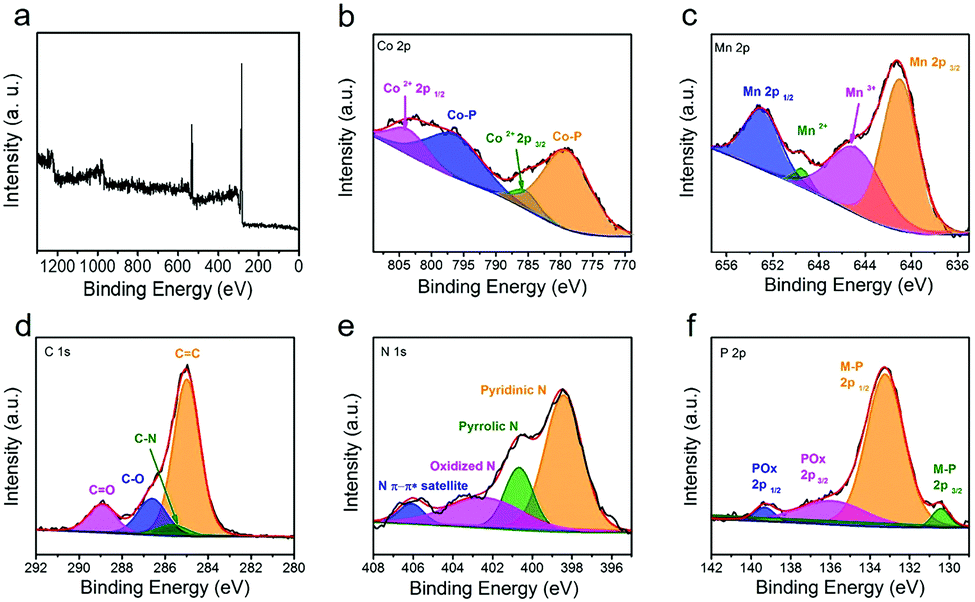 | ||
| Fig. 3 (a) XPS survey spectrum of CoMn-P@NG and the corresponding high-resolution spectra: (b) Co 2p, (c) Mn 2p, (d) C 1s, (e) N 1s and (f) P 2p. | ||
The linear scanning voltammetry (LSV) curves of CoMn-P@NG, CoMn@NG and Pt/C catalysts were tested at 5 mV s−1 in 1 M KOH (pH = 14), 0.5 M H2SO4 (pH = 0) and 1 M PBS (pH = 7) the results are shown in Fig. 4a, b and Fig. S5a (ESI†). According to the results in Fig. 4a, when the current density reaches 20 mA cm−2 in 1 M KOH, the overpotential of the CoMn-P@NG catalyst is 190 mV, while the overpotentials of the Pt/C and CoMn@NG catalysts are about 30 and 298 mV, respectively. Besides, under the acidic condition of 0.5 M H2SO4, the electrocatalytic performance of CoMn-P@NG is still excellent at 20 mA cm−2, and the overpotential is only 159 mV. The overpotentials of the Pt/C and CoMn@NG catalysts were approximately 30 and 254 mV (Fig. 4b), respectively. As can be seen in Fig. S5a (ESI†), the overpotential of the CoMn-P@NG catalyst is 279 mV, while the overpotentials of the Pt/C and CoMn@NG catalysts are about 79 and 370 mV, respectively. Under the conditions of pH = 0, pH = 14 and pH = 7, the overpotential of CoMn-P@NG is much smaller than that of CoMn@NG; the reason could be ascribed to the P atoms entering the bimetallic structure of the catalyst after doping. P is less electronegative than C and N, so it is easier to attract the positive charge of the core metal atoms, further leading to the downshift of the d-band center of the core bimetal, and thus the activation energy required for the reaction is reduced.34 Therefore, more active sites are generated in the CoMn-P@NG catalyst, and the electro-catalytic performance is greatly improved.35 Besides, as shown in Table S1 (ESI†), CoMn-P@NG demonstrates an overpotential of 164 mV and 140 mV at 10 mA cm−2 in alkaline and acidic solution, respectively, suggesting high potential application as a non-precious electrocatalyst for the hydrogen evolution reaction.
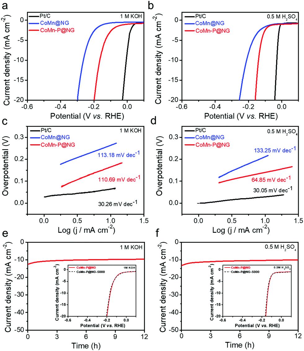 | ||
| Fig. 4 (a and b) LSV curves of CoMn-P@NG, CoMn@NG and Pt/C catalysts after normalizing the currents to the geometric area in different electrolytes. (c and d) Tafel plots of CoMn-P@NG, CoMn@NG and Pt/C catalysts were calculated from the LSV curves from (a and b). (e and f) HER stability measurements of CoMn-P@NG in different pH conditions at a current density of 10 mA cm−2 for 12 h. Inserted LSV curves tested initially and after 5000 ADT CV cycles. | ||
The Tafel slope is an important parameter to evaluate the HER kinetics of catalysts.36 The first step of the HER is the Volmer step, and the second is the Tafel step (slope value is 30–40 mV) or Heyrovsky step (slope value is 40–120 mV).37 The Tafel curves of Pt/C, CoMn@NG and CoMn-P@NG catalysts after internal resistance compensation are shown in Fig. 4c and d and Fig. S5b (ESI†). The Tafel slops of CoMn-P@NG under 1 M KOH (pH = 14), 0.5 M H2SO4 (pH = 0) and 1 M PBS (pH = 7) conditions are 111, 65 and 112 mV dec−1, respectively, which belonged to the Volmer–Heyrovsky reaction.38 The Tafel slope of CoMn-P@NG indicates that the second step reaction is the Heyrovsky reaction, so the desorption process is the speed-limiting process of the HER.39 The results show that the CoMn-P@NG catalytic kinetic energy is very high and the catalytic reaction rate increases faster with the increase of overpotential. In addition, the CV curve of CoMn-P@NG was measured under the scanning rate of 20–160 mV s−1, and its Cdl values in 1 M KOH and 0.5 M H2SO4 were 17.4 and 19.3 mF cm−2, respectively (Fig. S3, ESI†), suggesting that the catalyst has outstanding catalytic activity.
Furthermore, electron transfer kinetics and catalytic kinetics are effective factors affecting the HER. Electrochemical impedance spectroscopy (EIS) measurements for both CoMn@NG and CoMn-P@NG were carried out from 10−2 to 105 Hz at the same voltage (the potential is −1.16 V in 1 M KOH and −0.35 V in 0.5 M H2SO4, respectively). As shown in Fig. S4 and S5c (ESI†) compared with the CoMn@NG, CoMn-P@NG has a smaller semi-circle in the low-frequency region under pH = 0, pH = 14 and pH = 7 conditions, indicating that CoMn-P@NG has a lower charge transfer resistance and a faster charge transfer ability.40 This result demonstrates that phosphorus doping can accelerate the electron transfer ability and enhance the electrocatalytic activity.
Whether the catalyst has high stability is one of the key factors for its industrial applications. In order to explore the stability of the CoMn-P@NG catalyst, long-term stability tests were carried out under the current density of 10 mA cm−2 in solutions of 1 M KOH, 0.5 M H2SO4 and 1 M PBS, as shown in Fig. 4e and f and Fig. S5d (ESI†). The results show that the current density and potential have an ignorable change during the 12 h stability test. Besides, another stability assessment method, i.e., accelerated degradation tests (ADT), was also adopted to evaluate the stability of CoMn-P@NG, and after 5000 cycles, the overpotential of the CoMn-P@NG catalyst exhibits negligible change in 1 M KOH, 0.5 M H2SO4 and 1 M PBS from the inserted LSV curves in Fig. 4e and f and Fig. S5d (ESI†), showing the excellent stability of the CoMn-P@NG catalyst.
In summary, a CoMn phosphide encapsulated in a nitrogen-doped graphene core–shell heterostructure was successfully synthesized. Interestingly, the P was only doped into the CoMn bimetal core. The unique heterostructure exhibited excellent electrocatalytic properties over a wide pH range. When the current density reaches 20 mA cm−2 in the conditions of pH = 0, 14 and 7, the overpotential of the CoMn-P@NG catalyst is 159, 190 and 279 mV, respectively. In addition, the CoMn-P@NG catalyst maintains robust stability over a broad pH range environment.
Data curation-Jingjing Liu; investigation-Jingjing Liu, Zhe Cui, Jiaojiao Li; methodology-Jingjing Liu, Liping Huang and Caiyu Ma; supervision-Wenyao Li, Fang Yang and Min Zeng; writing-original draft-Jingjing Liu; writing-review & editing-Wenyao Li, Fang Yang and Min Zeng.
This work is financially supported by the NSFC (51602193, 21703267), Startup Fund for Youngman Research at SJTU, and the Foundation Research Project of Jiangsu Province (BK20170423).
Conflicts of interest
There are no conflicts to declare.Notes and references
- B. Y. Xiong, L. S. Chen and J. Shi, ACS Catal., 2018, 8, 3688 CrossRef CAS.
- S. Chu and A. Majumdar, Nature, 2012, 488, 294 CrossRef CAS.
- H. Wang, Q. Zhang, H. Yao, Z. Liang, H. Lee, W. Hsu, G. Zheng and Y. Cui, Nano Lett., 2014, 14, 7138 CrossRef CAS.
- J. Luo, J. H. Im, M. T. Mayer, M. Schreier, M. K. Nazeeruddin, N. G. Park, S. D. Tilley, H. J. Fan and M. Gratzel, Science, 2014, 345, 1593 CrossRef CAS.
- Z. H. Xiao, Y. C. Huang, C. L. Dong, C. Xie, Z. J. Liu, S. Q. Du, W. Chen, D. F. Yan, L. Tao, Z. W. Shu, G. H. Zhang, H. G. Duan, Y. Y. Wang, Y. Q. Zuo, R. Chen and S. Y. Wang, J. Am. Chem. Soc., 2020, 142, 12087 CrossRef CAS.
- C. G. Morales-Guio, L. A. Stern and X. Hu, Chem. Soc. Rev., 2014, 43, 6555 RSC.
- M. K. Debe, Nature, 2012, 486, 43 CrossRef CAS.
- X. Zou and Y. Zhang, Chem. Soc. Rev., 2015, 44, 5148 RSC.
- X. Yan, L. Tian, M. He and X. Chen, Nano Lett., 2015, 15, 6015 CrossRef CAS.
- W. Ahn, M. G. Park, D. U. Lee, M. H. Seo, G. Jiang, Z. P. Cano, F. M. Hassan and Z. Chen, Adv. Funct. Mater., 2018, 28, 1802129 CrossRef.
- Q. Liang, L. Zhong, C. Du, Y. Zheng, Y. Luo, J. Xu, S. Li and Q. Yan, Adv. Funct. Mater., 2018, 28, 1805075 CrossRef.
- X. Ma, C. Chang, Y. Zhang, P. Niu, X. Liu, S. Wang and L. Li, ACS Sustainable Chem. Eng., 2020, 8, 8318 CrossRef CAS.
- Y. Hu, J. O. Jensen, W. Zhang, L. N. Cleemann, W. Xing, N. J. Bjerrum and Q. Li, Angew. Chem., Int. Ed., 2014, 53, 3675 CrossRef CAS.
- L. Yu, D. H. Liang and X. H. Bao, Angew. Chem., Int. Ed., 2020, 59, 15294 CrossRef CAS.
- B. Du, Q. T. Meng, J. Q. Sha and J. S. Li, New J. Chem., 2018, 42, 3409 RSC.
- X. Xiao, C. T. He, S. Zhao, J. Li, W. Lin, Z. Yuan, Q. Zhang, S. Wang, L. Dai and D. Yu, Energy Environ. Sci., 2017, 10, 893 RSC.
- Z. Li, T. T. Zhao, W. J. Jiang, S. Niu, M. Wu and J. S. Hu, ACS Appl. Mater. Interfaces, 2018, 10, 35904 CrossRef CAS.
- Z. Z. Liang, Z. Y. Yang, J. S. Dang, J. Qi, H. T. Yuan, J. P. Gao, W. Zhang, H. Q. Zheng and R. Cao, Chem. – Eur. J., 2019, 25, 621 CAS.
- Z. Zafar, Z. H. Ni, X. Wu, Z. X. Shi, H. Y. Nan, J. Bai and L. T. Sun, Carbon, 2013, 61, 57 CrossRef CAS.
- C. Rabelo, T. L. Vasconcelos, B. C. Publio, H. Miranda, L. G. Cancado and A. Jorio, Phys. Rev. Appl., 2020, 14, 024056 CrossRef CAS.
- L. Bai, C. S. Hsu, D. T. L. Alexander, H. M. Chen and X. Hu, J. Am. Chem. Soc., 2019, 141, 14190 CrossRef CAS.
- L. M. Cao, Y. W. Hu, S. F. Tang, A. Iljin, J. W. Wang, Z. W. Zhang and T. B. Lu, Adv. Sci., 2018, 5, 1800949 CrossRef.
- H. F. Wang, C. Tang and Q. Zhang, Adv. Funct. Mater., 2018, 28, 1803329 CrossRef.
- D. Li, H. Baydoun, C. N. Verani and S. L. Brock, J. Am. Chem. Soc., 2016, 138, 4006 CrossRef CAS.
- Y. Y. Ma, C. X. Wu, X. J. Feng, H. Q. Tan, L. K. Yan, Y. Liu, Z. H. Kang, E. B. Wang and Y. G. Li, Energy Environ. Sci., 2017, 10, 788 RSC.
- G. Yan, X. Feng, S. U. Khan, L. Xiao, W. Xi, H. Tan, Y. Ma, L. Zhang and Y. Li, Chem. – Asian J., 2018, 13, 158 CrossRef CAS.
- J. Q. Chi, W. K. Gao, J. H. Lin, B. Dong, K. L. Yan, J. F. Qin, B. Liu, Y. M. Chai and C. G. Liu, ChemSusChem, 2018, 11, 743 CrossRef CAS.
- H. S. Jiang, S. Y. Zhao, W. Y. Li, T. P. Neville, I. Akpinar, P. R. Shearing, D. J. L. Brett and G. J. He, Green Energy Environ., 2020, 5, 506 CrossRef.
- H. Li, F. Ke and J. Zhu, Nanomaterials, 2018, 8, 89 CrossRef.
- X. Zhu, M. Liu, Y. Liu, R. Chen, Z. Nie, J. Li and S. Yao, J. Mater. Chem. A, 2016, 4, 8974 RSC.
- C. Ray, S. Lee, C. Jin, B. Kundu, A. J. H. Park and S. C. Jun, ACS Sustainable Chem. Eng., 2018, 6, 6146 CrossRef CAS.
- H. Jia, R. Jiang, W. Lu, Q. Ruan, J. Wang and J. C. Yu, J. Mater. Chem. A, 2018, 6, 4783 RSC.
- R. X. Jina, J. Huang and G. L. Chen, Chem. Eng. J., 2020, 402, 126257 CrossRef.
- W. F. Chen, K. Sasaki, C. Ma, A. I. Frenkel, N. Marinkovic, J. T. Muckerman, Y. M. Zhu and R. R. Adzic, Angew. Chem., Int. Ed., 2012, 51, 6131 CrossRef CAS.
- H. Wang, Q. Yi, L. Gao, Y. Gao, T. Liu, Y. B. Jiang, Y. Sun and G. Zou, Nanoscale, 2017, 9, 16342 RSC.
- H. Jin, J. Wang, D. Su, Z. Wei, Z. Pang and Y. Wang, J. Am. Chem. Soc., 2015, 137, 2688 CrossRef CAS.
- B. E. Conway and B. V. Tilak, Electrochim. Acta, 2002, 47, 3571 CrossRef CAS.
- X. Yan, L. Tian, M. He and X. Chen, Nano Lett., 2015, 15, 6015 CrossRef CAS.
- J. Guo, F. Li, Y. Sun, X. Zhang and L. Tang, J. Power Sources, 2015, 291, 195 CrossRef CAS.
- W. Wu, Y. Wu, D. Zheng, K. Wang and Z. Tang, Electrochim. Acta, 2019, 320, 134568 CrossRef CAS.
Footnote |
| † Electronic supplementary information (ESI) available. See DOI: 10.1039/d0cc07523j |
| This journal is © The Royal Society of Chemistry 2021 |