
Understanding active sites in molecular (photo)electrocatalysis through complementary vibrational spectroelectrochemistry
Khoa H.
Ly
 * and
Inez M.
Weidinger
*
* and
Inez M.
Weidinger
*
Lehrstuhl für Elektrochemie, Fakultät für Chemie und Lebensmittelchemie, Technische Universität Dresden, Andreas-Schubert-Bau, Zellescher Weg 19, 01069 Dresden, Deutschland. E-mail: hoang_khoa.ly@tu-dresden.de; inez.weidinger@tu-dresden.de
First published on 8th February 2021
Abstract
Synthetic molecular (photo)electrocatalysts have been intensively studied due to their capability to drive key energy conversion reactions. In order to advance their potential through rational development, an in-depth mechanistic understanding of the catalytic reactions is required. In this article, we highlight in situ vibrational spectro-electrochemistry, specifically, confocal Raman and infrared absorption spectroscopy, as a highly capable method for obtaining profound insights into the structure and reactivity of electrode-immobilised molecular catalytic systems. Commonly employed experimental configurations for carrying out in situ studies and conditions for operating in the surface-enhanced mode are presented. This is followed by selected research examples to showcase the different aspects and features of molecular (photo)electrocatalysis that can be visualised by vibrational spectroelectrochemistry. Presented target systems include porphyrin-based systems, polypyridyl-based complexes as well as phthalocyanine-based two dimensional conjugated metal–organic frameworks, and photoactive conjugated polymers. The article concludes with a critical assessment of current limitations of the techniques and gives a brief outlook on anticipated future developments.
Introduction
Electrochemically driven catalysis has the potential to become a key technology to challenge the immanent energy and environmental crisis.1 This process uses charges to drive chemical transformations and, hence, converts electrical energy into chemical energy and vice versa. Particularly, coupled to electricity harnessed from renewable energy sources, electrocatalysis enables the storage of the typically intermittent electrical energy through electrosynthesis of energy-dense compounds and thus enables the sustainable production of fuels as well as chemicals.2As most energy-relevant chemical reactions do not proceed without the presence of a catalyst, electrochemical charge transfer from the electrode is combined with the specific catalytic surface reaction of interest. The actual catalyst can be either the electrode itself (e.g. heterogeneous electrocatalysis) or a system that becomes catalytically active following a redox reaction at the electrode interface (e.g. molecular electrocatalysis).2,3 The driving force for the heterogeneous directional charge transfer is generated by an electrical voltage/potential polarising the electrode. Additionally, photo-active materials can be employed as electrodes, which, upon light absorption, generate photoexcited charges for driving the catalysis.4 A major advantage of photoelectrocatalysis (PEC) is the additional photovoltage created through charge excitation, lowering the overall applied voltage that is needed to activate the reaction cascade. Optimal materials employed as photocathodes or photoanodes should exhibit broad light harvesting features in the visible region and rapid charge separation/transportation rates.5
Several key energy conversion reactions rely on electrocatalysis, such as the hydrogen oxidation reaction (HOR) and the oxygen reduction reaction (ORR). Both reactions are coupled in a H2|O2 fuel cell. Here, H2 is oxidised on the anode side to yield protons (H+) and electrons (e−) that are used on the cathodic side to reduce oxygen in a 4e−/4H+ proton process, releasing non-toxic H2O as a product. Electrode-driven synthesis (electrosynthesis) of the fuel H2 is accomplished in the hydrogen evolution reaction (HER) under neutral and acidic conditions via the 2e− electroreduction of H+ to yield H2, whereas under basic conditions H2 evolves from the splitting of H2O to H2 and OH−. Last but not least, the electrocatalytic CO2 reduction reaction (CO2RR) has lately gained tremendous attention.2 This reaction process enables the conversion of the greenhouse gas CO2 to carbon-based fuels and feedstock chemicals. For example, the 2e−/2H+ electrocatalytic reduction of CO2 yields CO, which is used to produce hydrocarbons in the Fischer–Tropsch process at an industrial scale. Increasing the number of electron and proton transfer (ET and PT, respectively) steps during catalysis yields other relevant products and fine chemicals, such as methane and methanol, respectively.
The successful implementation of these key energy conversion reactions into competitive technologies strongly relies on the development of (photo)electrocatalysts that can efficiently orchestrate the sequences of ET and PT steps to yield a defined catalytic product. In particular, the catalyst is also needed to overcome the sluggish reaction kinetics associated with multiple ET/PT reaction cascades, which translate into high reaction overpotentials for activation of the catalytic reaction steps and thus significant energy losses. The major quest lies therefore in finding optimised catalytic systems offering tailored properties that allow the rate, energy efficiency, and selectivity of these chemical transformations to be increased.
Enzymes are the most efficient catalysts capable of promoting these relevant energy conversion reactions with almost no overpotential, i.e. close to the thermodynamic reaction potential, to yield one defined catalytic product. The key to the excellent catalytic efficiency of enzymes is their highly evolved active sites in which the catalytic reactions take place.6 Specifically, the substrate binding site, typically a coordinated high valent metal ion, is surrounded by a dedicated secondary coordination sphere that is directly involved in the catalytic cycle. The function of this sphere varies from stabilising specific bound reaction intermediates via electrostatic interactions to pre-organising H+ for efficient PT following redox events at the substrate to avoid the formation of high-energy charged intermediates.
Synthetic molecular catalysts that mimic enzymatic reaction sites have emerged as promising structures towards achieving artificial high efficiency electrocatalysis.6–8 These systems are typically of simple chemical nature and their structures can be chemically modified to fine-tune their catalytic properties. Complemented with in-depth mechanistic investigations, the study of molecular catalytic systems allows for deriving key structure–function relationships and identifying highly catalytically active chemical motifs. Assembly of such molecular structures by either polymerisation9 or metal coordination10 can moreover lead to extended macromolecular systems exhibiting a high density of active sites and enhanced catalytic performance. The modular build-up of such materials enables rational optimisation of several important aspects in (photo)electrocatalysis, such as coupling of active sites and, in certain cases, even tuning of optical band gaps.11
For technical use, heterogenisation of molecular catalytic systems, i.e. implementation on solid support electrodes, is mandatory.12 Tethering the structures to a conductive surface reduces the amount of deployed catalysts to a surface-bound layer that can be directly redox-controlled via application of an external electrical potential. Furthermore, it allows operating in aqueous medium, since most synthetic electrocatalysts are insoluble in water. A multitude of tailored heterogenisation strategies have been developed to achieve quantitative adsorption of fast and direct electro-addressable adsorbates with maintained catalytic activity.13,14
A major prerequisite for advancing the rational development of heterogenised synthetic (photo)electrocatalytic systems is the profound understanding of the interfacial reactions. However, mechanistic study of reactions of surface-confined catalysis is challenging. Electroanalytical techniques, such as electrolysis and cyclic and linear sweep voltammetry, provide mainly quantitative information on the catalysis/reactions and are thus typically employed to assess the catalytic performance.15 Obtaining direct molecular information on reaction steps and identification of formed intermediates, is key knowledge towards elucidating and understanding the catalytic mechanism, and requires the application of spectroscopic methods.
In this respect, vibrational spectroscopy coupled with electrochemistry, i.e. vibrational spectroelectrochemistry (SEC), has emerged as a powerful tool to gain profound insights into processes at active sites of heterogenised synthetic electrocatalysts.16–20 This feature article showcases our recent advancements of applying vibrational SEC in this field. We discuss experimental setups and design that enable sensitive in situ measurements to be carried out and present the wealth of information on the catalytic reactions that can be obtained. The complementary use of IR absorbance and confocal Raman SEC for disentangling proton and redox events, and identifying reaction sites is highlighted.
Vibrational spectroelectrochemistry
Vibrational spectroscopy, specifically Raman scattering and IR absorption spectroscopy, probes the interaction of molecular vibrations with light typically in the visible (Raman) and infrared (IR) frequency regions, and thus provides direct molecule specific information of the target system at an atomistic level. This versatile set of techniques has been widely used to identify redox and protonation processes as well as molecular binding events and structural transformations. In IR spectroscopy, IR light absorbance is used to detect molecular vibrations with the respective absorbed IR frequency directly corresponding to the energy of the molecular vibration. As IR selection rules require a change in dipole moment associated with the vibration, this technique is particularly sensitive to polar functional groups, such as carboxylic acids or carbon monoxide. Raman spectroscopy, on the other hand, is based on inelastic scattering of lights. Thus, Raman selection rules require a change in polarisability associated with the respective vibration. The technique is therefore specifically sensitive to probe conjugated (aromatic) systems, such as phenols or porphyrins, and highly suited to monitor large structural changes. A special case of Raman scattering is resonance Raman (RR) scattering. Here, the frequency of the exciting laser light is tuned to match an electronic transition of the target. The RR effect selectively enhances totally symmetric vibrations of the absorbing unit, while ordinary Raman signal contributions from other components or background become negligible. The magnitude of the enhancement scales with the oscillator strength of the respective electronic transition, and thus RR spectroscopy is typically employed when the sample exhibits at least a moderately strong electronic absorption in the visible region. As such, RR spectroscopy is widely used for the analysis of complex biological structures exhibiting chromophores, such as metallo-enzymes21 and bacteria.22In electrochemical Raman and IR (EC-Raman and EC-IR) spectroscopy, reactions at the electrode interface under the influence of an electrical voltage or during electrocatalytic turnover are spectroscopically monitored. This makes surface sensitivity and selectivity of these methods as well as applicability in aqueous environment mandatory. IR spectroscopy is highly sensitive towards water vibrations, which exhibit high IR extinction coefficients. Thus, IR total absorption by water bands can occur even at a thin layer of water, which significantly impedes a straightforward collection of IR spectra in aqueous medium. Therefore, EC-IR spectroscopy is typically carried out in the attenuated total reflection (ATR) mode (Fig. 1a).23 In this configuration, an IR active waveguide, e.g. Si prism, is employed on which the electrode material and target system are deposited and subsequently mounted into a spectroelectrochemical cell. Light illumination occurs from below. The incident IR beam is attenuated-total-reflected at the solid–liquid interface, giving rise to an evanescent IR wave that probes the IR absorbance of target molecules or thin films located within. The penetration depth of the wave depends among other factors on the indices of refraction of the waveguide and of the adjeacent medium, e.g. water.24 For commonly employed waveguide materials, such as Si and ZnSe, typical values for penetration depth range from 0.5 to 2 μm. Thus, to ensure that sufficient IR light is present at the electrode–liquid interface, the deposited electrode should be ultrathin and exhibit negligible IR self-absorption. Metal films with a thickness of several hundred nanometres (∼200 nm) as electrodes are typically constructed via electroless deposition25 or gas phase deposition techniques.26 Also, sub-micrometre thick carbon-based materials, e.g. graphite nanoparticle conglomerates,27 as well as micrometre thick porous metal oxide structures,28,29 have been established as suitable electrode material for (ATR) EC-IR spectroscopy.
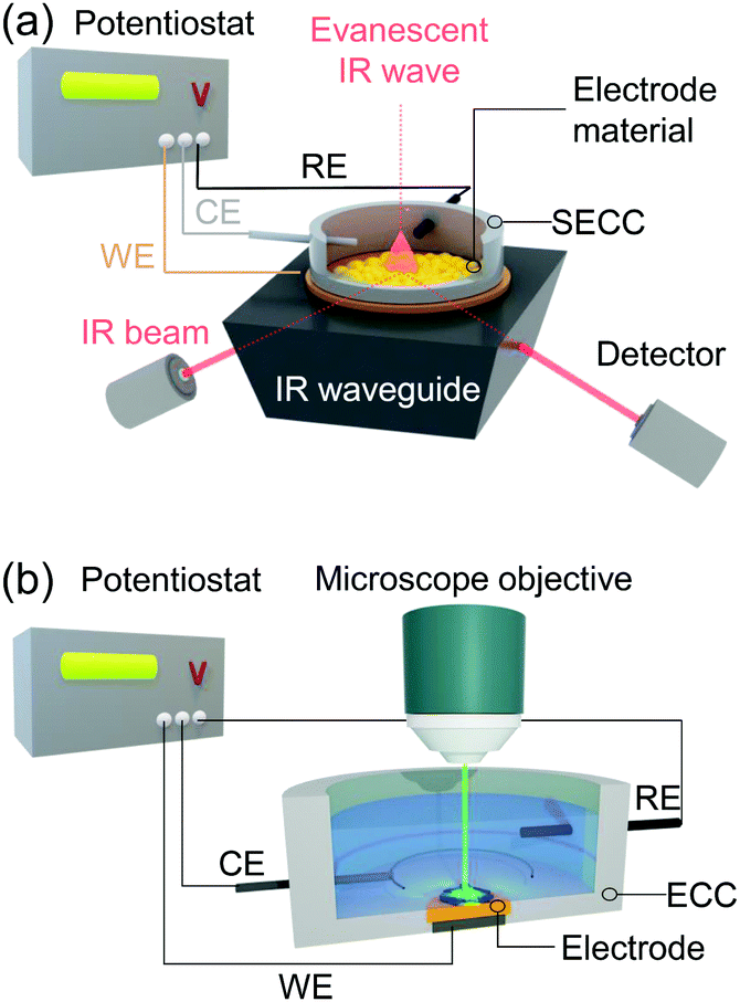 | ||
| Fig. 1 (a) EC-IR/EC-SEIRA setup in ATR configuration. The electrode material is deposited on the IR waveguide (e.g. Si prism) and electro-contacted as the working electrode (WE) in the spectro-electrochemical cell (SECC). CE and RE denote the counter and reference electrodes, respectively. (b) EC-Raman/EC-SER setup in the confocal mode carried out in standard electrochemical cells (ECCs). Exciting laser light focussed via the microscope objective on the sample-deposited WE. Electrical potentials are applied using a potentiostat. | ||
Raman spectroscopy can be directly applied to aqueous systems. EC-Raman spectra of thin films on electrode surfaces can be obtained in simple backscattering geometry in confocal mode (Fig. 1b). In this case, the exciting laser is focussed onto the electrode via a microscope objective, which also collects the Raman scattered photons. This configuration renders EC-Raman spectroscopy inherently surface sensitive and, furthermore, allows the use of standard electrochemical cells with only minor adjustments necessary regarding cell design. Laser light induced photochemistry is a common problem in this measurement configuration, which is especially pronounced in the case of RR spectroscopy. Particularly, for a monolayer of surface adsorbed molecular compounds, degradation of the sample is often observed upon extended laser illumination. This problem can be bypassed by choosing a cell design where the working electrode is periodically moved at a defined and tuneable frequency. Development of Raman SEC cells using a rotating working electrode with cylindrical geometry was pioneered by Hildebrandt et al.30 A spectro-electrochemical cell based on a rotating (ring) disc (RR(R)D) electrochemical cell was first presented by Dey et al. (Fig. 2a).31 This configuration offers the advantage that quantitative electrochemical analysis is standardised for this type of cell and can be conducted simultaneously with the Raman experiment, ensuring full comparability of electrochemical and spectroscopic data. Furthermore, the directed electrolyte flux in R(R)DE cells affords controlled mass transport to the disc working electrode. Catalytic products formed at the disc electrode are subsequently transported to the ring working electrode that can be separately poised with an electrical potential to induce a specific subsequent electrochemical reaction. This enables electrochemical detection of catalytic products; a procedure commonly employed in ORR electrocatalysis.32 Rotation dependent electrocatalytic efficiency, however, was found to be comparable for both rotating electrode setups.33
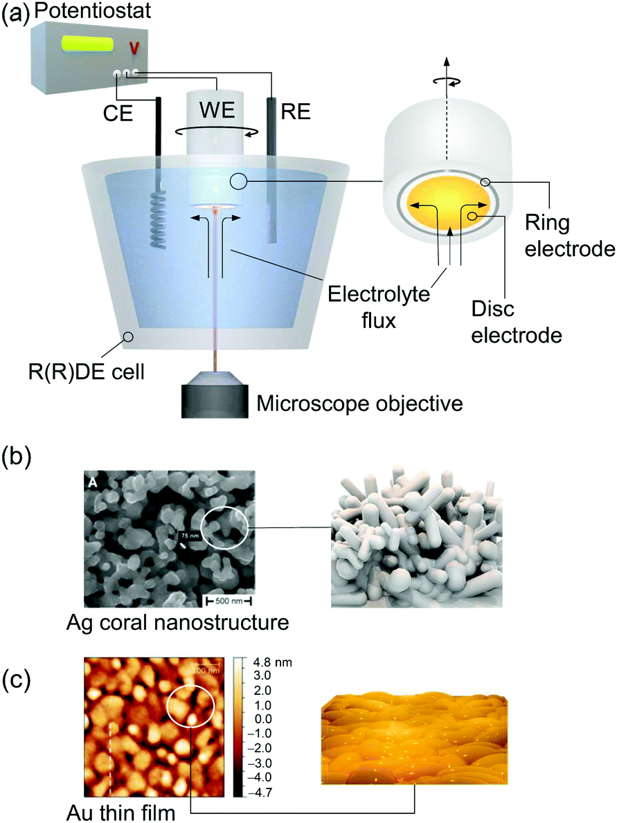 | ||
| Fig. 2 (a) EC-Raman/SER spectroscopy coupled to a rotating (Ring) disc electrode (R(R)DE) electrochemical setup. A microscope objective focusses the exciting laser onto the disc working electrode (WE). Rotation imposes a defined electrolyte flux. Potentials at the ring electrode can be separately adjusted. CE and RE denote counter and reference electrodes, respectively. (b) SEM image of a plasmonic Ag electrode obtained via electrochemical roughening. Reprinted from ref. 88. (c) AFM image of a nanoscopically rough Au electrode for EC-SEIRA spectroscopy obtained via electroless deposition on a Si prism. Reprinted from ref. 104. | ||
Enhancing the sensitivity of Raman and IR SEC
A critical issue arises from the inherently low sample concentration given by a monolayer of adsorbed compounds at an interface. The yielded surface coverages on typical flat electrodes are often too low to be detected with either conventional IR or Raman spectroscopy. Target films on electrodes need to be typically thicker than few micrometres in the case of Raman spectroscopy. Thus, nanostructured high surface area electrodes are employed which can drastically increase sample loading. In this respect, conductive mesoporous and inverse-opal metal oxide nanostructures, e.g. made of indium tin oxide or titanium dioxide, have been demonstrated to constitute formidable support electrodes enabling the sensitive IR28 and resonance Raman34,35 spectroscopic detection of surface-adsorbed molecules.An alternative approach is the application of surface enhanced vibrational SEC. Surface enhancement is typically obtained at a metal–dielectric interface via the generation of surface plasmon resonances (SPRs). This very confined light enhancement selectively enhances the spectroscopic signals of molecules within the dielectric layer in close proximity to the metal surface.36 Occurrence of SPRs requires the material to exhibit a certain nanostructured morphology and highly mobile electrons. The latter limits significant plasmonic surface enhancement to the coinage metals silver (Ag), gold (Au), and copper (Cu).37 Surface enhanced Raman (SER) spectroscopy was the first technique that was used to explore SPR-based signal enhancement of surface bound molecules. Ag is among the best support materials for SER analysis with average Raman signal enhancement factors around 103–105 and, so far, it is the only material that exhibits significant surface enhancement in the blue/violet/UV frequency region.38 A simple electrochemical roughening procedure can be applied to prepare SER active Ag electrodes with a random coral-like nanostructure that provide sufficient near field enhancement (Fig. 2b).39
Despite its unique optical properties, Ag is not an ideal electrode material for EC-SER studies due to its low oxidation potential. This prevents the application of Ag at high positive potentials, which impedes monitoring of many oxidation reactions. It is nevertheless a suitable support for typical reduction reactions, such as ORR or CO2RR. From a chemical point of view, Au electrodes are much better suited for SER spectroelectrochemical analysis. From an optical point of view, however, Au is less ideal for SER measurements as it can only be used for laser excitation wavelengths above ca. 550 nm. In principle, other transition metals can also be employed as SER support materials but are only rarely relied upon due to their low surface enhancement.39
The combination of SER with RR scattering yields surface enhanced resonance Raman (SERR) scattering and allows selective monitoring of chromophore structures attached to metal surfaces even at submonolayer coverages.40 The only requirement to obtain SERR scattering is the match of the electronic absorption of the sample (RR enhancement) and SPR resonance of the plasmonic support electrode.
The spectro-electrochemical cell shown in Fig. 1b can be adapted for EC-SER(R) spectroscopy in a facile manner by for example employing plasmonic Ag or Au as the working electrode material. The enhancement of the Raman signal scales with the 4th power of the electromagnetic field enhancement, resulting in a very steep dependence of the obtained signal on the distance from the electrode.41 This effect limits the number of layers for which SER signals are obtained to a few nanometres above the metal interface, rendering the method hihgly surface selective.
Electrochemical surface enhanced infrared absorbance (EC-SEIRA) spectroscopy can be conducted by coating the ATR waveguide, e.g. Si-prism, with a thin nanostructured metal film (ca. 200 nm). For Au, suitable films can be obtained on Si via electroless deposition from a gold salt (Fig. 2c).25 IR signal enhancement scales with the second power of the electromagnetic field enhancement. Consequently, the signal enhancement is less strictly confined to the metal–dielectric interface compared to EC-SER spectroscopy. EC-SEIRA spectra thus give information on molecules within a layer of ca. 10 nm thickness on the electrode surface.25
Porphyrin-based systems
Porphyrin-based active sites are common in biological catalysis. They are found in enzymes specialised in the transformation of oxygen, e.g. cytochrome c oxidase and cytochrome p450, or that of hydrogen peroxide, e.g. catalase and peroxidase. Interestingly, nature uses the same motifs for oxygen transportation in haemoglobin or myoglobin where oxygen is only bound to the porphyrin metal but not transformed. This excellent reaction selectivity is achieved by the presence of a second coordination sphere in close proximity to the catalytic site providing additional anchors for hydrogen bonds or proton supply. Enzymatic active sites have thus been used as raw models for the synthesis of porphyrin catalysts exhibiting a similar second coordination sphere. A variety of such tailored porphyrin derivatives have been synthesised so far specifically to enhance their activity for ORR and HER electrocatalysis.42,43Structural analysis of porphyrin-based systems in chemistry and biology via RR spectroscopy has a long history. The RR spectra obtained with violet light excitation in resonance with the Soret band absorbance of the porphyrin provide information on the redox and spin states of the central metal and their dependence on the nature of the axial ligands.44,45 Structural changes of immobilised porphyrin catalysts in the presence of an applied electrical potential can be monitored via EC-SERR spectroscopy, which has been used in the past by us and others to determine midpoint potentials46,47 and heterogeneous electron transfer rate constants48,49 and to identify reaction intermediates during electrocatalytic turnover.31,50
Fe–Hangman complexes
A facile and effective implementation of a secondary coordination sphere is provided by so-called Hangman complexes, initially designed by the Nocera group51,52 and further developed by the group of M. Schwalbe.53 These complexes consist of a porphyrin/corrole catalytic site and a carboxylic functional group separated by a xanthene linker bridge (Fig. 3a). The hanging carboxyl group prevents porphyrin aggregation and potentially acts as a proton relay to achieve fast PT reactions. The distance between the central metal of the porphyrin and the carboxylic group is 0.4 to 0.8 nm, which is sufficiently close to allow hydrogen bonding interactions with the bound substrate. | ||
| Fig. 3 Non-turnover EC-SERR spectra of heterogenised porphyrin-based Fe complexes on RRDEs in the presence (a) and absence (b) of a second coordination sphere. The spectra of the complex lacking a second coordination sphere show incomplete reduction and heterogeneity of states. Laser excitation: 413 nm, reference electrode: Ag/AgCl 3 M KCl. Graphs redrawn from ref. 33 and 56. | ||
Hangman complexes accommodating Fe as the central metal were shown to exhibit increased oxidase and catalase activity compared to their counterparts that lacked the additional hanging group.53,54 However, since the complexes are insoluble in water, these experiments were exclusively performed in organic solution, where the hanging group is expected to be protonated. Neumann et al. incorporated Fe–porphyrin complexes with and without a hanging group into a polymer matrix on a glassy carbon electrode via electro-polymerisation.9 These experiments allowed the electrocatalytic ORR properties of heterogenised Fe–Hangman complexes to be tested in an aqueous environment and also confirmed a better catalytic activity in respect of a lower onset and half wave potential under these conditions if the hanging group was present. Yet the “Hangman effect” was much less pronounced than observed for solubilised complexes in organic medium.
The redox potential and dynamics of Fe–porphyrins directly influence their electrocatalytic activity. To elucidate the effect of the carboxylic acid hanging group on these redox properties, the structural changes of immobilised Fe–Hangman complexes as a function of applied potential and pH were investigated via EC-SERR and EC-SEIRA spectroscopy. The SERR effect selectively enhances the totally symmetric vibrations of the porphyrin macrocycle. Here, the ν4 and ν2 modes occur at around 1360 and 1550 cm−1, respectively, and are characteristic of the redox and spin states of the metal, respectively.55 Potential dependent SERR spectra were compared for porphyrins with and without a second coordination sphere (Fig. 3a & b). If the hanging group is lacking, the reduction of the porphyrin remains incomplete in the potential range between −0.1 and −0.5 VAg/AgCl (vs. Ag/AgCl 3 M KCl) and the presence of at least two spin states is indicated.56 It is suggested that the high amount of redox inactive species is a result of porphyrin stacking leading to the formation of electrochemically inactive Fe–O–Fe/Fe–O–O–Fe species.57 The presence of a second coordination sphere prevents the formation of electro-inactive oxygen adducts and thus increases the percentage of redox active species on the surface and, at −0.5 VAg/AgCl, complete reduction is observed.33 The ν4 and ν2 vibrations shift to slightly higher wavenumbers and the presence of only one spin state is indicated. This notably improved homogeneity of states and redox activity is proposed to be a result of the carboxylic hanging group that, on the one hand, prevents porphyrin stacking and, on the other hand, is able to stabilise the reduced FeII–OH species via hydrogen bonding interactions.
EC-SERR spectroscopy selectively displays the structural changes of the porphyrin, which might be influenced by the hanging group. However, the signal intensity of the group itself, which is not resonantly enhanced under 413 nm excitation, is too weak to be monitored. On the other hand, direct information on the hanging group can be derived by SEIRA spectroscopy, since IR spectroscopy is sensitive to the very polar vibrations of the carboxylic acid and carboxylate group. We performed SEIRA spectroscopy on immobilised Fe–Hangman complexes in an aqueous electrolyte at different pH values to identify the COOH/COO− transition of the hanging group (Fig. 4a). By following the ν(C![[double bond, length as m-dash]](https://www.rsc.org/images/entities/char_e001.gif) O) of the –COOH group and the νas(COO−) band, a pKa of 3.4 of the hanging carboxylic acid group in an aqueous environment (0.1 M potassium phosphate buffer solution) was determined experimentally for the first time.57
O) of the –COOH group and the νas(COO−) band, a pKa of 3.4 of the hanging carboxylic acid group in an aqueous environment (0.1 M potassium phosphate buffer solution) was determined experimentally for the first time.57
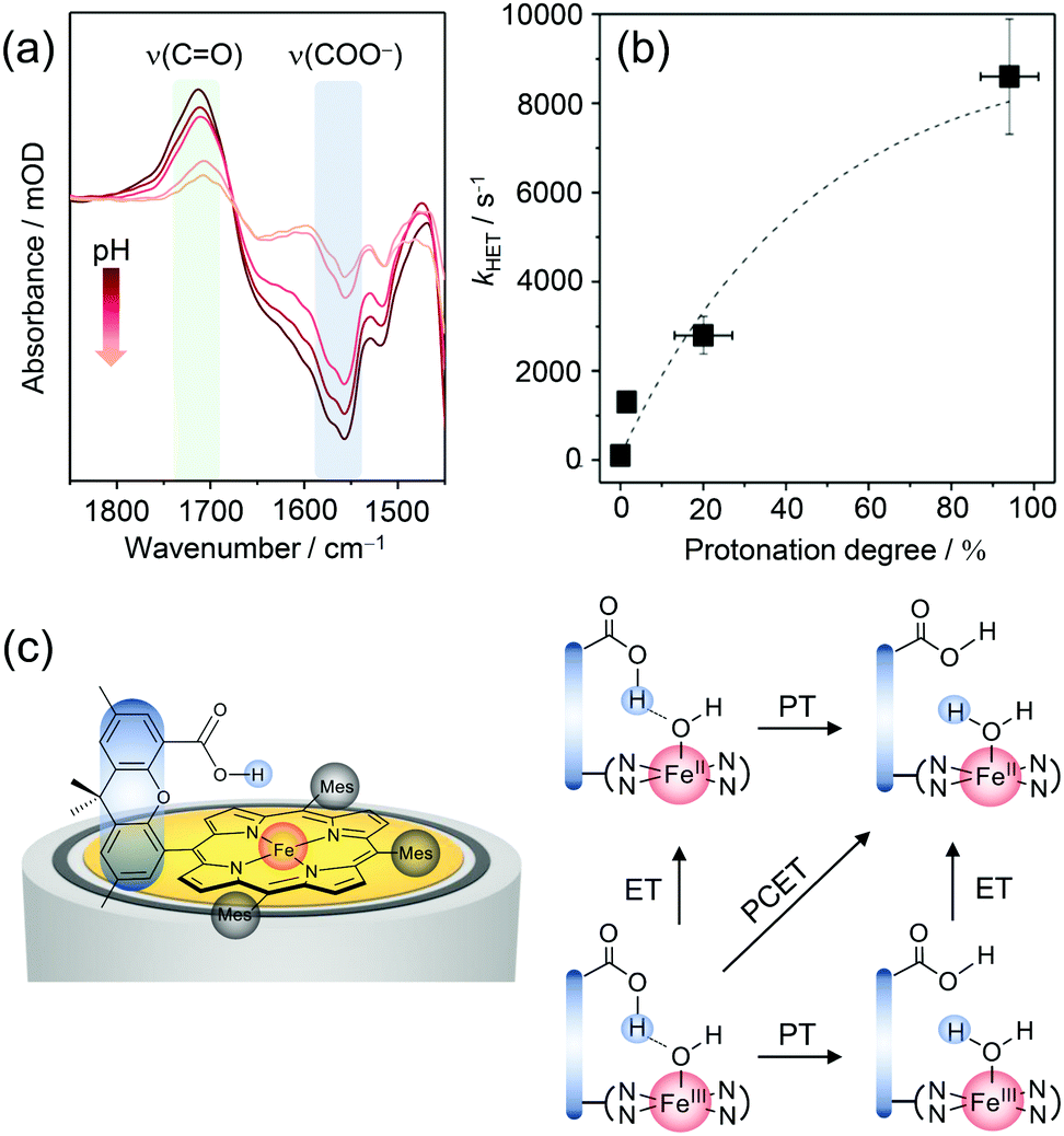 | ||
| Fig. 4 (a) pH dependent SEIRA spectra showing the protonation of the carboxylic acid hanging group upon lowering the pH. (b) Correlation between the rate of porphyrin reduction (kHET) and protonation grade of the hanging group. (c) Proposed scheme for proton-coupled electron transfer (PCET) in Fe–Hangman complexes with a protonated carboxylic acid hanging group. Graphs and scheme redrawn from ref. 57. | ||
The protonation degree of the hanging group determines its function as a proton relay and thus potentially influences the catalytic activity of the complexes. The significant difference in the protonation degree of the hanging group in organic and aqueous solutions could be a reason for the less pronounced “Hangman effect” in the latter. Fast reduction of the central metal iron is a prerequisite for high catalytic turnover and might be affected by protonation/deprotonation of the hanging group. To verify such a correlation, complementary EC-SERR and SEIRA measurements were combined. The heterogeneous electron transfer rate (kHET) from the electrode to the porphyrin iron was determined via time-resolved EC-SERR spectroscopy and plotted against the protonation degree of the hanging group derived from SEIRA measurements (Fig. 4b). A clear dependence could be seen with an increasing ET rate for higher protonation degrees. The results not only confirm the direct influence of the hanging group on porphyrin redox chemistry but also support the role of the carboxylate as a proton relay. In this respect, it is speculated that the presence of the protonated carboxylic acid hanging group might be able to stabilise axial OH/OH2 ligation due to hydrogen bonding interactions (Fig. 4c). Furthermore, the proton relay effect may enable concerted proton-coupled electron transfer (PCET) avoiding high energy intermediates with either electron or proton excess.
Co–Hangman complexes
Replacing Fe by Co in Hangman systems has been shown to yield good catalysts for the HER.58,59 Based on electrochemical measurements, it was stated that under acidic conditions the reaction starts from a CoI oxidation state and proceeds via PT from the hanging group, resulting in the formation of a CoIII–H intermediate that has to be further reduced to CoII–H prior to hydrogen evolution. Due to the “Hangman effect” the overpotential for H2 generation was lowered. Again, these experiments were conducted in organic solution in which complete protonation of the carboxylic hanging group is expected. Therefore, these results cannot be generally extended to heterogenised catalysts and aqueous environments.Applying EC-SERR spectroscopy, we thus investigated the influence of the carboxylic group on Co–Hangman HER chemistry in the case where the complexes were immobilised on an electrode and surrounded by aqueous solution.60 Two Co–Hangman complexes were compared, one accommodating a methyl ester and a carboxylic acid functionality, with only the latter being able to function as a proton relay (Fig. 5a & b). Both complexes exhibited similar spectroscopic patterns under non-turnover conditions corresponding to potentials below −1 VAg/AgCl independent of the electrolyte pH. Under turnover and acidic conditions (pH 4), however, a significant difference was observed in the EC-SERR spectra as only for the carboxylic acid group bearing Hangman complex a new band at 1418 cm−1 appeared (Fig. 5b). Predictions from DFT calculations allowed this band to be assigned to a porphyrin vibration in the CoI state. The absence of this band for the ester group bearing complex seems puzzling at first but can be explained by the proton shuttling ability of the carboxylic hanging group. It is assumed that in both complexes the CoIII–H intermediate is formed from the CoI state at negative potentials (Fig. 4c). Subsequent molecular H2 formation requires the interaction of two CoIII–H complexes or reduction to CoII–H followed by protonation. Since this process is fast, the SERR spectra will predominantly probe the resting CoII state. However, in the carboxylic group bearing complex the Co bound hydrogen can interact with the carboxylic hanging group and, upon laser illumination, is able to perform a photo-assisted PT, converting the complex back to its CoI state. The EC-SERR spectra therefore probe the back reaction from CoIII–H to CoI, exclusively in the presence of a carboxylic hanging group, proving their proton relay function.
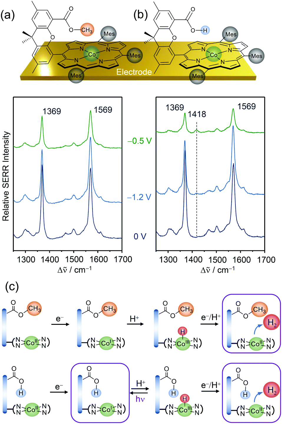 | ||
| Fig. 5 EC-SERR spectra of heterogenised Co–Hangman complexes (Mes = mesityl) on electrodes exhibiting an ester (a) or a carboxylic acid (b) functionalised hanging group in aqueous electrolyte at pH 4. (c) Proposed reaction scheme under HER turnover conditions and light exposure. The framed states are probed by EC-SERR spectroscopy. Graphs and schemes redrawn from ref. 60. | ||
Conjugated polypyridyl-based systems
Conjugated polypyridyl-based metal complexes have gained attention as molecular catalysts for energy conversion reactions.61 The versatile polypyridyl ligand framework is capable of stabilising low metal oxidation states as well as accepting reducing charges in its π system. Moreover, the electronic configuration of polypyridyl coordinated metal complexes can be tuned by varying the substitution pattern at the pyridine groups, which has enabled rationally steering activity and product selectivity of the promoted catalytic reactions.62The metal (M) bipyridine fac-tricarbonyl complex or [MX(bpy)(CO)3] (bpy = 2,2′-bipyridine; X = halogenide) and M bisterpyridine or M(tpy)2 (tpy = terpyridine) are two simple polypyridyl-based complexes that have been extensively studied.61 Both types of complexes have been shown to catalyse the HER and CO2RR in organic solvents.61,63 Particularly, manganese (Mn) bipyridine fac-tricarbonyl and cobalt (Co) bisterpyridine complexes have emerged as potentially interesting candidates with relevant application as molecular electrocatalysts and co-catalysts in PEC to drive the specifically challenging CO2RR under aqueous conditions.62
Manganese bipyridine fac-tricarbonyl complexes
The complex [MnBr(bpy)(CO)3] (bpy = 2,2′-bipyridine) (Mnbpy) has emerged as a noble metal-free model catalyst towards CO2RR in organic media.64 The redox and electrocatalytic reactions of Mnbpy towards CO2 and protons have been studied in depth using a multitude of techniques, such as synthetic chemistry, electrochemistry, and IR SEC. The redox chemistry of the complex is strongly dependent on the nature of the substituent(s) R at the bipyridine unit (bpy-R, with R as the substitution group).65 Electroreduction of Mnbpy-R with R = H, Me, tBu in acetonitrile is accompanied by two 1e− transitions at −1.7 and −1.9 VFc+/Fc.66 In the first reduction step, dehalogenation leads to the formation of a radical which prompts the formation of the dimeric Mn0–Mn0 species that is subsequently reduced to the anionic species [Mn(bpy-R)(CO)3]− in the second reduction step. Under a CO2 atmosphere, CO2 reduction electrocatalysis is proposed to be initiated by the dimeric as well as the anionic complex at respective potentials.Structural information on the redox states of Mnbpy-R has been derived from IR SEC conducted in transmission mode.65 In this configuration, an optically transparent thin layer spectro-electrochemical cell is employed, in which the dissolved complex is oxidised and reduced by a thin Au mesh working electrode. The absorption of IR light passing through the thin solvent layer provides information on the complexes in their respective potential-equilibrated redox state. Here, three carbonyl ligands of Mnbpy-R function as IR reporter groups (Fig. 6a). The resulting ν(CO) modes appear in the isolated frequency window from 1800 to 2100 cm−1 and are highly sensitive to the configuration, e.g. oxidation and coordination state, of the complex.67
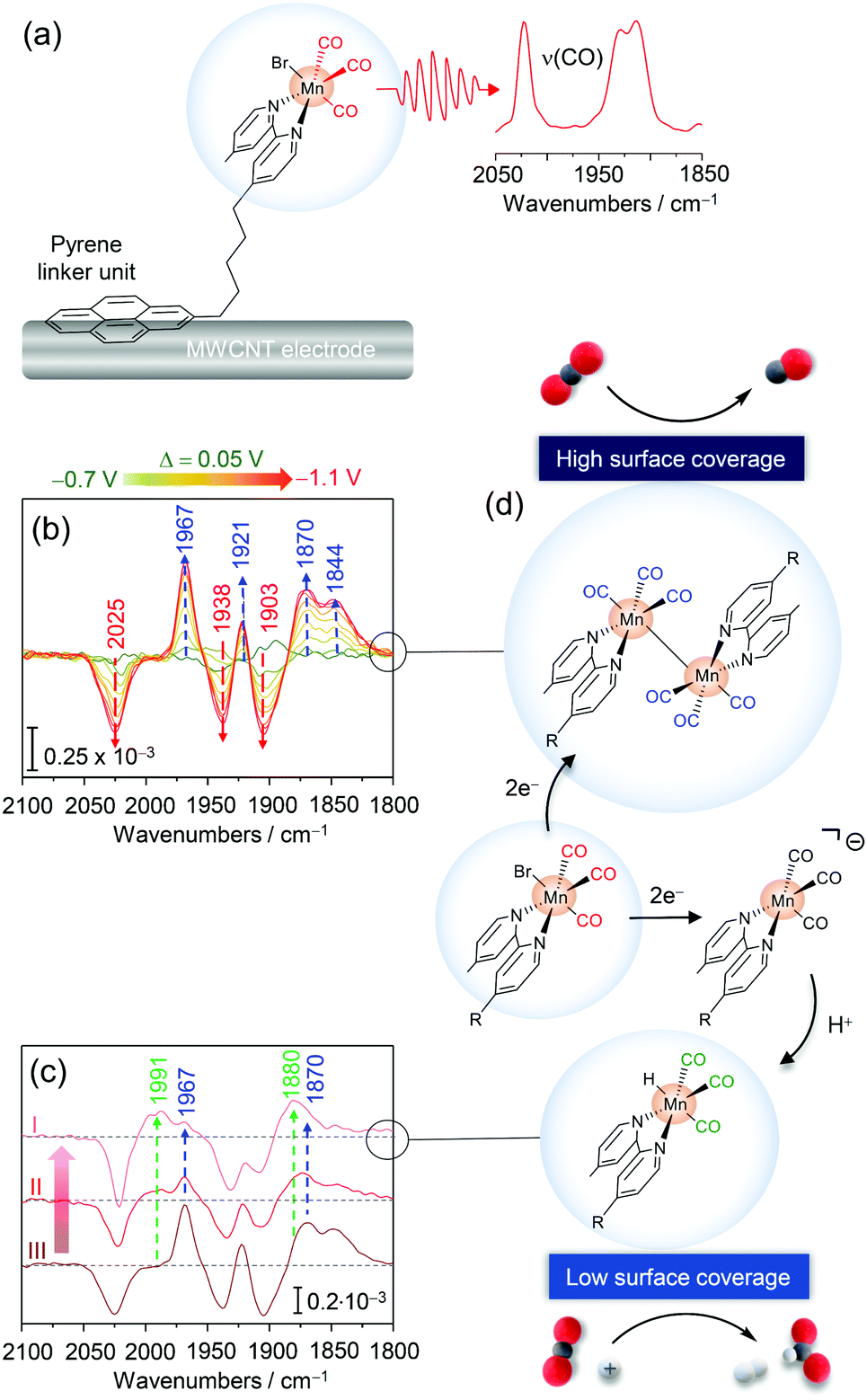 | ||
| Fig. 6 (a) Pyrene modified Mn fac-tricarbonyl complex immobilised on a multiwalled carbon nanotube (MWCNT) electrode. (b) Potential dependent EC-IR difference spectra revealing the formation of the Mn–Mn dimer species (blue arrows) upon reduction of the parent MnPyr species (red arrows). (c) EC-IR difference spectra with decreasing surface coverages of MnPyr (from III to I) revealing the formation of a Mn hydride species (green arrows). (d) Scheme for surface coverage dependent redox chemistry and catalytic CO2RR selectivity of immobilised MnPyr. Graphs and schemes redrawn from ref. 68. | ||
Mnbpy-R complexes have been heterogenised by the Reisner group by modifying the bipyridine framework to bear a pyrene (Pyr) accommodating linker unit (MnPyr or fac-[MnBr(bpyPyr)(CO)3]) (Fig. 6a).68 Exploiting the affinity of pyrenes to conjugated carbon structures via π–π interactions, MnPyr was quantitatively immobilised on multiwalled carbon nanotube (MWCNT) support electrodes. Under aqueous conditions (0.5 M KHCO3), immobilised MnPyr yielded a high performance CO2RR electrocatalyst generating CO and formate (HCOO−) as carbon products. Remarkably, selectivity towards CO and HCOO− was found to be dependent on the surface loading of MnPyr. Lowered surface coverages led to preferential CO production, while lowering the Mnpyr coverage yielded formate (or HCOO−) (and H2) as the major product. In line with other heterogenised complexes, electrochemical characterisation of immobilised Mnpyr under aqueous conditions is challenging as no clear non-turnover electrochemical signals of the complex could be recorded.
The redox and catalytic chemistry of heterogenised MnPyr was thus investigated via EC-IR spectroscopy. The IR active catalyst-loaded working electrode was assembled by transferring a thin MWCNT layer onto a Si prism as the waveguide to allow sufficient penetration of the evanescent IR wave into the electrode material and adjacent solution. MnPyr immobilised on the MWCNT coated Si prism under full aqueous conditions (0.5 M KHCO3, Ar purged) exhibited strong ν(CO) bands at 2022, 1930, and 1912 cm−1 for the as-adsorbed complex, reflecting the parent oxidised state. Potential-dependent IR difference spectra with stepwise decreased potentials showed the appearance of four ν(CO) bands at ca. 1968, 1921, 1870, and 1844 cm−1 below −0.8 VSHE (vs. standard calomel electrode, SHE), indicating the formation of the Mn0–Mn0 dimer species upon reduction (Fig. 6b). These spectral changes were associated with the decrease of signals of the parent Mn state and, overall, indicated that reductive dimer formation also occurs under full aqueous conditions, which has not been directly observed before. Reversible reoxidation of the dimer was observed when switching back to potentials above −0.2 VSHE. No signals of the anionic Mn complex were detected also at lower potentials. Presumably, due to the high surface loading and confinement of MnPyr within the MWCNT matrix, dimer formation is significantly preferred. At first sight, it seems counterintuitive that the dimer can form, given that the complexes are ‘wired’ to the MWCNT surface. However, in a previous study using phosphonic acid modified Mn complexes immobilised on mesoporous TiO2 electrodes dimerization was also observed.69 This points to a certain level of lateral flexibility retained upon heterogenisation. The role of this lateral mobility in catalysis needs to be investigated in future studies.
Upon lowering the surface loading of MnPyr, an alternating spectroscopic behaviour was noted. Surface-bound dimer formation was found to be suppressed upon reduction at −1.0 VSHE, indicated by the lowered intensity of respective marker bands (Fig. 6c). Instead, the formation of a novel reduced species with marker bands at 1991 and 1880 cm−1 was observed (Fig. 6c) which could be assigned to a Mn hydride adduct species (Mn–H).70 This species is presumably formed upon protonation of the anionic Mn species. In this respect, the absence of signals of the anionic Mn species in the IR spectrum also at a low surface coverage may stem from the use of water as the solvent. As such, the abundancy of protons available could lead to a fast protonation of the (transient) anionic Mn species, while subsequent protonation of the Mn–H might be in turn slow(er), resulting in the accumulation of the Mn hydride species and hence spectroscopic detection.
In combination with electrochemical data, EC-IR spectroscopy derived data provide a rational basis for rationalising the reactivity and surface-coverage-dependent selectivity of immobilised MnPyr (Fig. 6d). Here, the surface coverage dictates the formation of the reactive catalytic species, i.e. dimer and Mn–H, with the former being active towards CO and the latter towards HCOO− and H2. It should be noted that previous studies with the catalyst in solution suggest that the anionic species is also capable of catalysing CO2-to-CO conversion.65
Cobalt bisterpyridine complexes
Adding a third pyridine group to bipyridine yields the highly versatile terpyridine ligand. Specifically, Co(II) bisterpyridine or [Co(tpy)2]2+ (tpy = terpyridine) complexes have gained attention as robust molecular electrocatalysts for CO2RR.63The Reisner group successfully immobilised Co bisterpyridine complexes on mesoporous metal oxide (photo)electrodes through the introduction of a phosphonic acid group (Fig. 7a).71 Due to their ability to form covalent oxygen–metal bonds, phosphonic acid groups are commonly employed as molecular linkers to graft catalytically active complexes onto metal oxide support electrodes.72 Specifically, the modified Co(II) bisterpyridine complex (CotpyP) was heterogenised as a co-catalyst onto p-Silicon (Si) photoelectrodes covered with a protective layer of mesoporous TiO2 which simultaneously functioned as high surface area scaffold. The assembled photoelectrode showed photo-electrocatalytic CO2-to-CO conversion performance in H2O (proton donor) containing acetonitrile (MeCN) as well as under full aqueous conditions (0.1 M KHCO3).
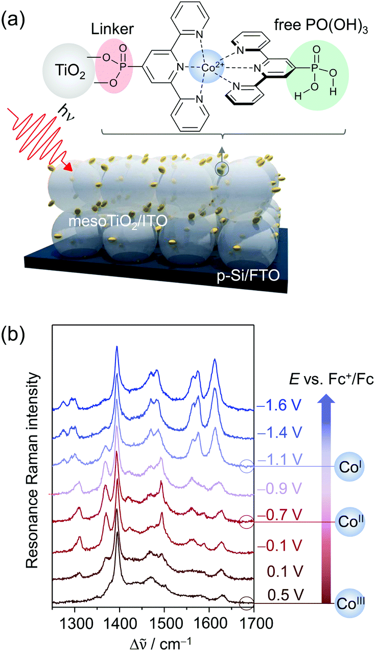 | ||
| Fig. 7 (a) Phosphonic acid modified Co bisterpyridine adsorbed on mesoporous TiO2 or ITO (mesoTiO2/mesoITO). (b) EC-RR spectra revealing the reduction of adsorbed CotpyP on mesoITO from CoIII to CoII to CoI in the potential range from 0.5 VFc+/Fc to −1.6 VFc+/Fc (514 nm excitation, acetonitrile with 0.1 M TBABF4). Graph redrawn from ref. 71. | ||
Under non-turnover conditions, cyclic voltammetry experiments with CotpyP immobilised on mesoporous indium tin oxide (mesoITO) on conductive FTO glass for conductivity reasons revealed intense redox couples centred at −0.12 VFc+/Fc (vs. ferrocene) and −1.36 VFc+/Fc which could be assigned to the CoIII/II (E1) and CoII/I (E2) redox transition, respectively. Upon the addition of H2O, an additional redox couple at ca. −1.10 VFc+/Fc (E3) was observed which represented the redox event CoII/I of a novel CoItpyP* species formed through the altered solvent composition. Under CO2 conditions, electrocatalytic current enhancement is observed beyond −1.0 VFc+/Fc, indicating that both CoItpyP* and CoItpyP are catalytically active.
To obtain molecular information on immobilised CotpyP on mesoITO and its redox chemistry, confocal EC-RR spectroscopy was employed. Excitation at 514 nm matching the metal-to-ligand charge transfer transition of adsorbed CoIItpyP was chosen to obtain high quality RR spectra selectively of the adsorbed complexes with suppressed contributions from the mesoITO background as well as the solvent to the overall spectra. Dominated by terpyridine vibrations with major bands at 1345, 1473, 1483, 1544, 1569, and 1599 cm−1 in the high frequency window (1200 cm−1 to 1700 cm−1), the RR spectrum of the as-adsorbed CotpyP matched the reported spectral features for other Co as well as Fe and Ru bisterpyridine complexes under RR conditions.73 Structural information was derived by comparing the 514 and 413 nm RR spectra of adsorbed CotpyP to the spectra of CotpyP powder as well as related model complexes, e.g. monoterpyridine Co chloride complex or [CoIICl2tpy]. The analysis revealed a retained bisterpyridine ligation of CotpyP in the immobilised state also in the presence of a hydrous organic electrolyte solution.
Potential-dependent RR spectra of CotpyP under non-turnover conditions (anhydrous MeCN with 0.1 M TBABF4) revealed distinct reversible spectral changes in the frequency range from 1200 to 1700 cm−1 (Fig. 7b). Across the investigated potential window from 0.5 VFc+/Fc to −1.6 VFc+/Fc, three redox states of CotpyP were identified which interconverted upon switching from positive to negative potentials and vice versa. Above 0 VFc+/Fc, the RR spectra showed the fully oxidised CoIIItpyP species with a weakly pronounced spectral pattern featuring bands at 1561 cm−1 and 1611 cm−1, besides contributions from the solvent (MeCN at 1375 cm−1 marked with an asterisk). Stepwise lowering of the potential revealed a set of peaks at 1345, 1473, 1542, and 1603 cm−1 rising after passing −0.4 VFc+/Fc, representing the RR marker bands of CoIItpyP. At potentials more negative than −1 VFc+/Fc, the spectral features of CoIItpyP were replaced by a set of new peaks at 1466, 1556, and 1593 cm−1 assigned to CoItpyP. The reversibility of all spectral features upon switching back to anodic potentials from −1 VFc+/Fc indicated a maintained structure and, more specifically, a retained bisterpyridine ligation upon redox state change.
Quantitative analysis of the EC-RR spectra can be achieved through component fit analysis.48 This approach allows disentangling spectral contributions from different species to the overall spectrum and, hence, calculating relative intensities as well as relative concentrations74 if the RR cross sections of each species are known. The plotted relative intensity of marker bands for each CotpyP state as a function of potential yielded sigmoidal curves that reflect their redox interconversion (Fig. 8a). The formal potentials of the CoIII/II and CoII/I transitions calculated by fitting the Nernst equation to the spectroscopically derived data set matched the values derived from cyclic voltammetry experiments, indicating that, in the absence of water, immobilised CotpyP is represented by its three redox states, all of them exhibiting retained bisterpyridine ligation.
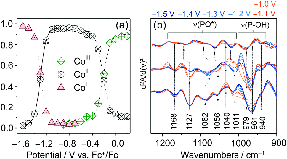 | ||
| Fig. 8 (a) Potential dependent relative intensity of the three redox species of CotpyP derived from component fit analysis of EC-Raman spectra. (b) EC-IR difference spectra of CotpyP on mesoITO in the 2nd derivative mode reflecting the change of protonation state of the free phosphonic acid group upon reduction to CoItpyP (hydrous acetonitrile with 0.1 M TBABF4). Graphs redrawn from ref. 71. | ||
The effect of water addition to the electrolyte solution and CO2 purging on the chemistry of the immobilised complexes was investigated by employing a combination of EC-RR and EC-IR spectroscopy. The EC-RR investigation revealed that both changes of solvent conditions impact solely the CoItpyP species, which is in line with cyclic voltammetry data. While the RR spectra of CoIIItpyP and CoIItpyP were unaffected by water content and CO2 purging, the RR spectra of CoItpyP featured a single pH (i.e. proton concentration of the solvent) sensitive band at 1546 cm−1. This observation is indicative of the presence of a pH sensitive equilibrium between two CoItpyP species, i.e. CoItpyP and CoItpyP*, with almost matching RR spectral patterns and one species lacking or showing a strongly diminished band at 1546 cm−1. Complementary EC-IR studies provided additional clues. Here, a thin mesoITO layer was deposited on a Si prism that acted as the working electrode. The potential dependent IR difference spectra (Fig. 8d), shown in the 2nd derivative mode to enhance the spectral changes (reference spectrum: catalyst-free mesoITO at the respective potential), revealed substantial changes specifically in the phosphonate region from 1250 to 900 cm−1 after reaching CoItpyP conditions, i.e. <−1.0 VFc+/Fc, when water was added. The IR spectral features suggest a change of protonation state in the phosphonic acid group.
Based on these data, it was hypothetised that the pH sensitivity is mediated by the free phosphonic acid group. Protonation and deprotonation of this substituent in para position effectively alters the electronic properties of the Co centre. This could modulate the RR enhancement of certain vibrational modes, such as the 1546 cm−1 band, and, hence, explain its depletion. Due to its frequency lying in the ν(CN) and ν(CC) region, the 1546 cm−1 band potentially reflects collective pyridine ring vibrations and, as such, should be sensitive to electron density changes at the Co centre as well as at the ligand frame itself.
The vibrational spectroscopically derived coexistence of two CoItpyP species that are connected via a protonation equilibrium at the free phosphonic acid group in water-containing solvent mixtures provided a basis for understanding the nature of the 3rd redox couple E3 detected via cyclic voltammetry (vide supra). Combining spectroscopic and electrochemical data, the reduction of CoIItpyP bearing a deprotonated phosphonic acid group is proposed to proceed via a less energetically demanding PCET (E3) to yield a protonated CoItpyP–H (CoItpyP*) or via an ET process to yield CoItpyP (E2), followed by a PT. Both CoI species are catalytically active, while only CoItpyP* accommodates a preorganised proton at its phosphonic acid group in proximity to the Co metal centre, potentially facilitating PT to bound reaction intermediates analogous to the “Hangman” effect as described for Fe– and Co–Hangman complexes.
2D conjugated phthalocyanine-based metal–organic frameworks
Layered two-dimensional conjugated metal–organic frameworks (2D c-MOFs) are an emerging class of porous and highly crystalline extended macromolecular systems with relevant application potential as electrocatalysts for energy conversion reactions.75 In addition to the advantageous properties of conventional MOFs, 2D c-MOFs also possess full in-plane π-delocalisation in two dimensions and a weak out-of-plane π–π stacking character and thus exhibit high electron conductivity, rendering them ideally suited for electrochemical reactions. Moreover, these systems intrinsically carry a high density of exposed coordinated metal centres that can act as molecularly defined active sites for various catalytic reactions. Chemical tunability of the robust organic scaffold as well as of the structural motifs of the active sites furthermore enables fine-tuning of the properties of 2D c-MOFs as electrocatalysts to steer their activity and selectivity towards specific reactions. In this respect, 2D c-MOFs bearing Co–S476 and Ni–N4,77i.e. respective metal ions coordinated by four sulphur or nitrogen atoms, motifs have been shown to be efficient electrocatalysts for HER and ORR, respectively.Very recently, the Feng group has introduced M1-phthalocyanine (Pc) based 2D c-MOFs with M2–O4 oxygen linker nodes (Pc|M1–O8|M2) via solvothermal methods (Fig. 9a).78,79 Here, M1 and M2 denote different types of metal ions, which can be varied independently. As such, these bimetallic 2D c-MOFs accommodate two exposed coordinative metal centres that, both, can act as active sites for electrocatalysis. It could be shown that by varying the nature of the metal ions in the phthalocyanine unit (M1N4) and the oxygen nodes (M2O4), respectively, the catalytic activity and selectivity of the 2D c-MOF can be rationally steered.
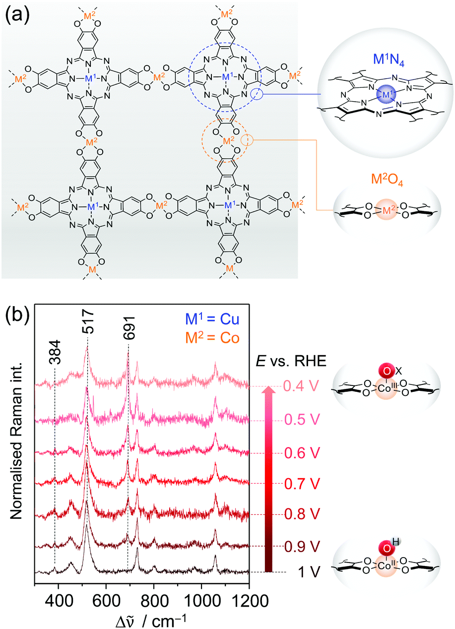 | ||
| Fig. 9 (a) Structure of bimetallic 2D c-MOFs consisting of phthalocyanine units (blue circle) linked via oxygen nodes (orange circle). M1N4 and M2O4 denote the two metal centres in the respective coordination environment. (b) EC-Raman spectra of CNT-Pc|Cu–O8|Co during ORR (413 nm excitation, 0.1 M KOH) suggesting the formation of the CoIII–Ox intermediate at 691 cm−1. Scheme and graph redrawn from ref. 79. | ||
Zhong et al. demonstrated that the layered 2D c-MOF Pc|Cu–O8|Co (M1 = Cu; M2 = Co) can function as a high performing ORR electrocatalyst.79 Hybridised with MWCNTs to increase the overall conductivity, CNT-Pc|Cu–O8|Co showed remarkable O2-to-H2O (n = 3.93) conversion activity in 0.1 M aqueous KOH with an onset potential of 0.83 VRHE (vs. reversible hydrogen electrode, RHE) and a limiting current density of jL = 5.3 mA cm−2 at a 1600 rpm rotational frequency in RDE experiments. Comparative electrochemical experiments of CNT-Pc|Cu–O8|M2 (M2 = Cu, Fe, Ni), CNT-Pc–O8|Co (no Cu in the Pc unit), and CNT-Pc|Cu–(OH)8 (Pc monomer on CNT) indicated also a synergistic effect between the Pc–Cu unit and the CoO4 linker node for catalysis.
We have investigated the different derivative versions of the 2D c-MOF deposited on a graphite electrode during catalysis via in situ EC-Raman spectroscopy to identify the nature of the active site for ORR.79 Potential dependent Raman spectra under 413 nm excitation recorded under turnover conditions revealed significant spectral changes exclusively for the CNT-Pc|Cu–O8|Co system, i.e. when CoO4 nodes are present. Upon immersion of CNT-Pc|Cu–O8|Co into an O2 saturated electrolyte solution, two bands at 384 and 517 cm−1 were observed reflecting CoII–OH modes (Fig. 9b).80 Stepwise lowering of the potential from 1 VRHE led to a decrease of both bands, accompanied by a concomitant increase of a band at 691 cm−1, after passing the onset potential for ORR at ca. 0.9 VRHE. The normalised intensity of the 691 cm−1 band plotted as a function of applied potential yielded a saturation curve, indicating an accumulation process of the underlying species. It is thus suggested that the 691 cm−1 band represents a Co bound oxygen intermediate (CoIII–Ox) that is formed in the catalytic cycle and accumulates with increasing overpotential due to faster kinetics.81 Formation of this species occurs at the expense of the CoII–OH species, which is likely the resting state in aqueous medium. In conclusion, the in situ EC-Raman data indicated that CoO4 nodes in CNT-Pc|Cu–O8|Co 2D c-MOFs are the active sites for ORR electrocatalysis. This hypothesis was corroborated by DFT calculations predicting a high binding energy of the peroxy intermediate Co–OOH− at the CoO4 sites, favouring its formation.
The electrocatalysis of layered CNT-Pc|M1–O8|M2 could be further steered by changing the metal composition, i.e. the nature of M1 and M2. The Feng group demonstrated that, for M1 = Cu or Zn and M2 = Cu or Zn, the resultant 2D c-MOF system effectively catalyses CO2RR to CO with concomitant hydrogen evolution in aqueous medium.78 The molar ratio of the product gas mixture CO:H2 was found to be sensitively dependent on the nature of M1 and M2 and the applied (over)potential. The different combinations CNT-Pc|Cu–O8|Zn, CNT-Pc|Zn–O8|Zn, CNT-Pc|Cu–O8|Cu, and CNT-Pc|Zn–O8|Cu yielded decreasing ratios for the faradaic efficiency (FE) for CO and H2, indicating metal-dependent activity and selectivity of the active sites towards CO2RR and HER, respectively.
We have employed EC-SEIRA spectroscopy to investigate the layered 2D conjugated CNT-Pc|M1–O8|M2 MOFs under turnover conditions (0.1 M KHCO3, CO2 purged) to reveal the nature of the active sites for CO2RR and HER, respectively. For CNT-Pc|Cu–O8|Zn and CNT-Pc|Zn–O8|Cu, strong bands in the spectral region from 2000 to 1400 cm−1 were noted in potential dependent SEIRA difference spectra (Fig. 10a & b). The intense positive bands in the range of 1660–1640 cm−1 in the SEIRA spectra of both MOF systems were assigned to interfacial H2O that is likely accumulating in the MOF layers due to catalysis or increasing negative polarisation of the electrode. More interesting are the bands in the isolated frequency region above 1800 cm−1 to 2100 cm−1. The bands at 1933 and 2071 cm−1 (not shown) were assigned to CO bound to the CuN4 and CuO4 centres, respectively. The different ν(CO) frequency stems from the altered electronic properties of Cu due to the respective coordination sphere. CuN4 can stabilise CO via π back bonding leading to lowered ν(CO), while CO bound to Cu and oxide-derived Cu surfaces has been reported above 2000 cm−1. The strong band centred at 1851 cm−1 for CNT-Pc|Zn–O8|Cu likely represents a Cu hydride (H–Cu) intermediate that is stabilised in the CuO4 nodes and formed in the HER cascade.82 The high relative intensity of this band suggests a dominating HER process over CO2RR at CNT-Pc|Zn–O8|Cu, in line with the results from electrochemical characterisation. H-Cu was not observed at the CuN4 units of CNT-Pc|Cu–O8|Zn. The absence of a H–Cu signal may, in this case, be rationalised by either fast protonation of the hydride species or fast intramolecular PT kinetics from the CuN4 complexes to ZnO4 sites, enhancing the overall CO2RR that predominantly takes place at the ZnO4 sites. Consequently, CO bound to the ZnO4 sites was not observed, which may stem from fast CO deliberation kinetics resulting from weaker CO binding with Zn. The SEIRA spectroscopic results are in line with predictions from DFT calculations indicating stronger binding of the high energy key intermediates for CO2RR and HER, i.e. metal bound *COOH and *H, on M2O4 and M1N4 centres, respectively. In this respect, a lowered Gibbs free energy for the formation of *COOH on the route to CO was predicted on ZnO4 over CuO4, corroborating that ZnO4 in CNT-Pc|Cu–O8|Zn is the dominant active site for CO2RR.
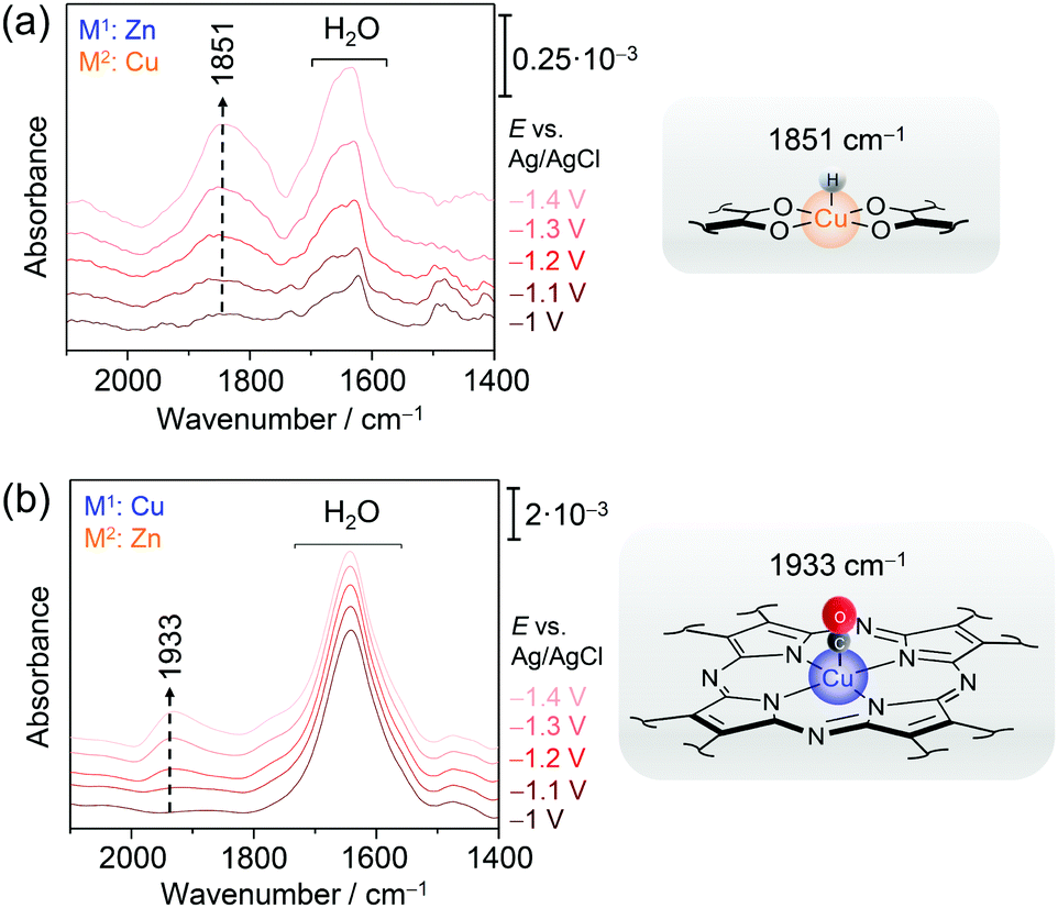 | ||
| Fig. 10 EC-SEIRA difference spectra of CNT-Pc|Zn–O8|Cu (a) and CNT-Pc|Cu–O8|Zn (b) under CO2RR conditions (0.1 M KHCO3). The rising band at 1851 cm−1 reflects the formation of the hydride species H-CuO4 in the CuO4 motif. In the presence of a CuN4 structure motif, binding of a CO to CuN4 is observed by a redshifted ν(CO) mode at 1933 cm−1. Graphs redrawn from ref. 78. | ||
Conjugated acetylenic polymers
Conjugated acetylenic polymers (CAPs), consisting of thiophene, benzene, and acetylene units, were introduced by the Feng group as efficient and low-cost metal-free photocathode materials for photoelectrochemical HER.83 Due to the modular setup of these CAPs, the band gaps of these materials became highly tuneable which allowed the solar light conversion to be extended to lower radiation energies. The lowest band gap of 2.17 eV (corresponding to 571 nm) was obtained for poly(2,5-diethynylthieno[3,2-b]thiophene) (pDET, Fig. 11a) grown on copper supports that also exhibited the highest HER efficiency. For this system, a benchmark PEC HER performance with a photocurrent of 370 μA cm−2 at 0.3 V and an incident photon to converted electron (IPCE) value of 12.6% at 520 nm under simulated solar light irradiation was measured.84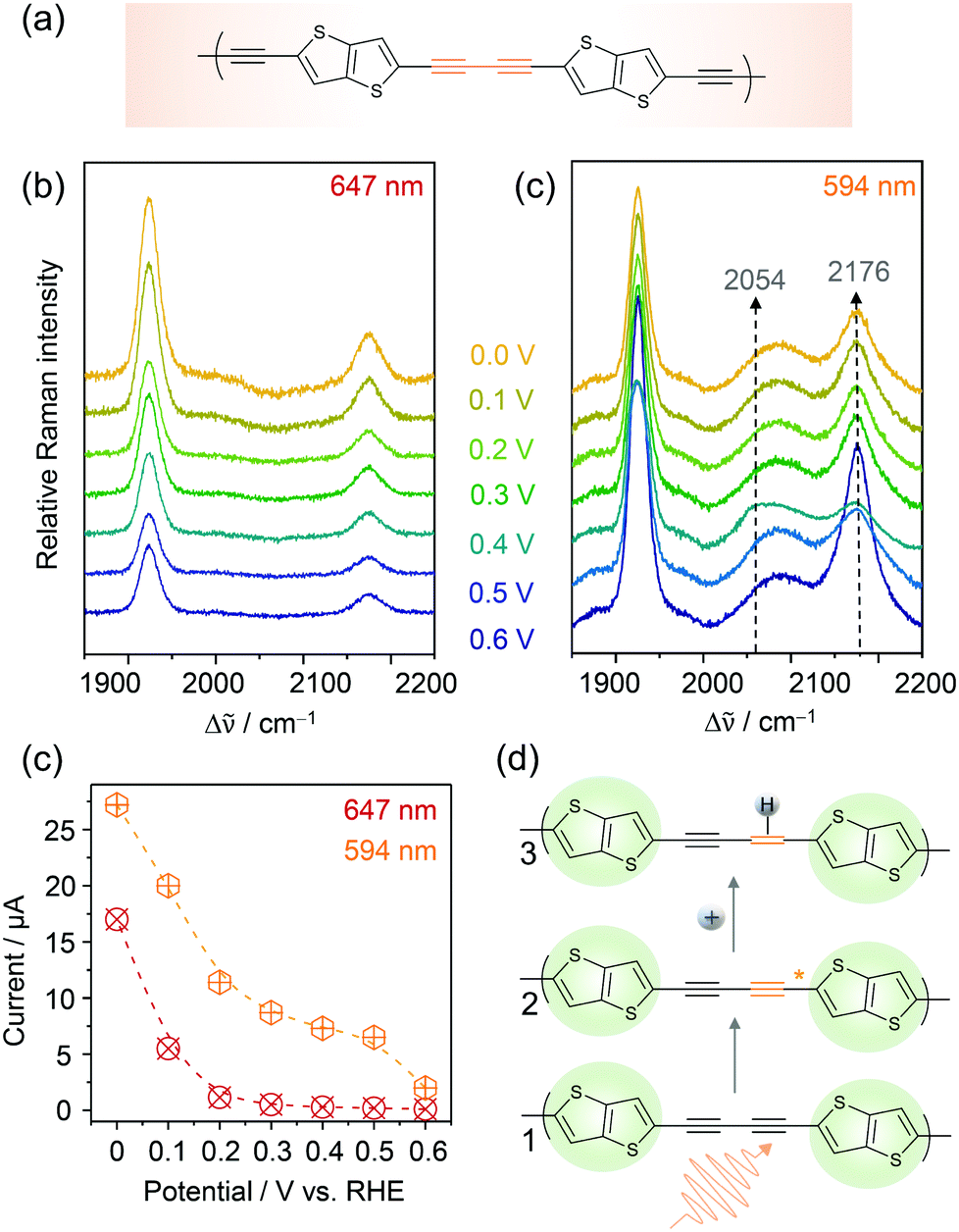 | ||
| Fig. 11 EC-Raman spectra of Cu/pDET using 647 nm (a) and 594 nm (b) laser excitation. (c) Potential dependent currents for HER as a function of excitation wavelength. (d) Proposed photoelectrocatalytic reaction scheme for photo-assisted hydrogen evolution. The resting (1) and intermediate states (3) exhibiting photo-activated C–C triple bonds prior to hydrogen attachment are observed in the EC-RR spectra of (b). Graphs and scheme redrawn from ref. 84. | ||
We investigated pDET on Cu foam electrodes via EC-Raman spectroscopy to identify the active site for photoinduced hydrogen evolution.84 Two laser lines were used for that purpose, one line (647 nm) being below and one line (594 nm) being close to the electronic band gap of the polymer. EC-Raman spectra obtained under 647 nm laser excitation showed two C–C triple bond vibrations of the acetylenic unit at 1924 and 2174 cm−1 which did not change with the increasing overpotential for HER (Fig. 11a). Concomitantly monitored potential dependent HER currents (Fig. 11c) featured an onset potential for HER activity around 0.2 V vs. RHE. EC-RR spectra under 594 nm laser excitation on the other hand featured an additional band at 2089 cm−1 and a transient band at 2054 cm−1 that appeared below 0.5 V at the expense of the 2174 cm−1 band (Fig. 11b). The measured currents upon 594 nm light illumination were higher compared to those under 647 nm illumination and HER currents were already observed at 0.5 V vs. RHE (Fig. 11c). It is proposed that the transient band at 2054 cm−1 corresponds to a triple bond vibration albeit with significantly decreased bond strength. No photoactivation was experimentally observed by EC-Raman spectroscopy for the thiophene units, which were therefore excluded as active sites for PEC HER. They play, nevertheless, an important role in band gap tuning and might also contribute to the electrocatalytic HER at a higher overpotential. Based on these measurements, the acetylenic units were identified as active sites for photoinduced hydrogen activation. In the proposed reaction scheme (Fig. 11d) the acetylene unit is initially photoactivated. In the activated state, more electron density is pushed into the C–C triple bond, which causes weakening of the bond strength seen as a shift to lower wavenumbers in the EC-Raman spectra. These activated acetylenic units with an increased electron density are thus attractive sites for hydrogen adsorption. Once the hydrogen is attached, the C–C triple bond becomes a double bond. Since no transient C–C double bond vibration, expected in the region between 1700 and 1600 cm−1, was observed in the EC-Raman spectra, it is assumed that this intermediate state has a very short lifetime and is immediately followed by molecular hydrogen formation and release. Furthermore, we cannot exclude the fact that laser induced hydrogen desorption, as observed in the case of Co–Hangman complexes, impedes the spectroscopic observation of this state.
As an interesting sidenote it should be mentioned that EC-Raman spectra in full resonance with the pDET absorbance maximum did not show any intermediate states. This is on second thought reasonable if one considers that, in this case, the RR effect predominantly enhances the resting state. Laser excitation using a laser line slightly below the band gap, i.e. 594 nm, might be in better resonance with the activated state and thus more sensitive to this intermediate.
Current limitations and future development
Currently, the intrinsically low sensitivity of Raman and IR spectroscopy still hampers their wide application in (photo)electrocatalysis research. This holds true for molecular systems as well as for heterogeneous electrocatalysis, where EC-SER and EC-SEIRA spectroscopy have been employed only more recently.82 Exploiting light enhancement from the support electrode is an elegant approach to amplify Raman and IR signals; however, such optical properties are generally limited to nanostructured noble metal supports. As these materials are also good electrocatalysts towards most energy conversion reactions, passivation of their surfaces is required to enable a dedicated assessment of the catalytic properties of immobilised target compounds via electroanalytical techniques. Also, plasmonic light enhancing materials do not necessarily act as sole light amplifiers for spectroscopy but, due to the strong near-field enhancement, are also capable of promoting and undergoing chemical reactions under light illumination.85 In the absence of light, the highly nanostructured surfaces required for the generation of SPR can give rise to local electric field effects that have impact on electrochemical reactions promoted at the material interface.86,87 As such, the employed light enhancing support material may have a significant impact on the integrity and (electro)chemistry of sample molecules adsorbed on their interfaces. Such effects need to be considered when working with plasmonic materials.In fact, it would be most desirable to be able to directly obtain meaningful vibrational spectroscopic signals from support materials that are commonly employed in heterogenised molecular electrocatalysis, such as graphite and related carbon-based electrode materials. Future development in this direction may involve plasmonic supports that are chemically passivated using graphene, MWCNT layers, graphite particle assemblies, etc., to yield an optically active hybrid device exhibiting a carbon surface for the binding of target compounds. Hybrid metal–metal/metal oxide electrodes consisting of a plasmonic Ag support chemically passivated with a layer of a specific metal as the binding surface, such as Au,88 Pt,89 Fe2O390 or TiO2,91 have already been constructed by us and others. These hybrid devices exploit the optical activity of Ag to enable sensitive SER detection at the chemically accessible outer metal/metal oxide layer via long-range plasmon coupling.
In the last few years, highly ordered semiconductor materials as photonic crystals have been tested regarding their light enhancing properties.92,93 Traditional metal oxide semiconductors, such as ITO and TiO2 exhibiting highly ordered nanostructures, e.g. inverse opal structure or ordered nanotube94 and nanorod arrays,95 have been shown to bear the potential to compete with traditional plasmonic materials as conductive light enhancing supports, particularly for SER spectroscopy.96 These systems can also be further combined with carbon materials29,97 to provide a carbon-based binding surface. More generally, by moving towards traditional light absorbing semiconductors, surface enhanced spectroscopy could be directly combined with semiconductor mediated photocatalysis,98 which would significantly extend the applicability of operando spectroscopic methods in the field of photo-electrocatalysis.
Achieving enhanced sensitivity for EC-Raman and EC-IR spectroscopy may become a game changer for heterogenised molecular electrocatalysis research as it would allow increasing the depth of information that can be spectroscopically derived. For example, short-lived transient intermediate species are often not detectable. This entails that the most active reaction pathway may not monitored. Thus, to derive mechanistic information, it is usually wise to study the system also under non-turnover conditions. Monitoring the system at potentials close to the catalytic onset could reveal crucial details about its reactivity, such as preceding catalytically relevant structural changes. To elucidate mechanistic processes, time-resolved (TR) EC-Raman/SER and EC-IR/SEIRA spectroscopy would be desirable. The TR mode would allow the identification of (transient) reaction intermediates as well as monitoring of kinetic and dynamic processes of the target catalytic system; mechanistic key information that cannot be derived in the static mode. In the past, we have successfully employed TR EC-SERR40 and EC-SEIRA25 to investigate redox kinetics and dynamics of plasmonic Ag electrode-immobilised biosystems, e.g. heme enzymes48,99 and catalytically active bacterial biofilms.100 The measurements were performed by synchronising spectroscopic measurement intervals with potential jumps that trigger the redox or catalytic reaction, e.g. by jumping to a potential value beyond the onset potential.101 For EC-SER(R) spectroscopy, this was achieved by chopping the detecting laser light using Pockels cells to yield short illumination intervals at defined delay times subsequent to the potential trigger pulse.30 In the case of EC-SEIRA spectroscopy, a Fourier-transform IR spectrometer capable of performing measurements in the step-scan mode was used to record the time evolution of IR signals following the potential trigger. Both experimental configurations can be directly employed for TR investigation of heterogenised molecular (photo)electro-catalysis. However, the typically very short spectroscopic measurement intervals required to achieve relevant time resolutions, e.g. milliseconds, could entail impracticable long accumulation times, which hampers the wide application of both methods. Thus, TR EC-SERR and EC-SEIRA studies have largely been limited to systems exhibiting high RR cross sections and/or deposited on traditional plasmonic supports, i.e. Ag and Au.57 This may very well change when, in the future, the sensitivity of Raman and IR spectroscopy can be increased as discussed earlier in the text.
EC-Raman and EC-SER spectroscopy can potentially induce photoreactions. This effect is less pronounced when investigating oxygen intermediates, but can become critical when monitoring hydride intermediates which may be photoconverted and hence are not detectable.60,102 EC-IR or EC-SEIRA measurements, on the other hand, are able to monitor the metal hydride vibration non-invasively and therefore are better suited for such studies. Thus, due to their complementary character, combined analysis via Raman/SER and IR/SEIRA on one system is highly desirable. However, spectroelectrochemical setups and experimental conditions for both methods are different, which makes a direct comparison of the experimental data non-straightforward. Recently developed nanoscopic gradient films exhibit, depending on the lateral position, surface enhancement ranging from the visible to the IR region and thus may constitute a promising support for enabling combined measurements.103 Last but not least, it would be highly desirable to cross-couple the investigation with other capable vibrational spectroelectrochemical techniques, such as electrochemical sum frequency generation spectroscopy.17
Concluding remarks
We highlighted vibrational SEC as a versatile tool for analysing the structure and reactivity of active sites of heterogenised molecular catalysts under the influence of electrical potentials as well as during (photo-)electrocatalytic turnover. It uniquely complements electrochemical techniques, such as cyclovoltammetry or chronoamperometry, which exclusively address the electroactive parts of the system and, hence, are largely blind to catalyst transformation and inactive or slow reacting components. Particularly, Raman and IR spectroscopy are comparably less cost-intensive techniques and offer a multitude of established experimental configurations that facilely allow measurements to be conducted under in situ/operando conditions. With the ongoing development of novel light enhancing materials and spectroscopic/spectroelectrochemical equipment, the sensitivity and, hence, the applicability of these methods are expected to be greatly expanded in the future, laying the foundation for exciting research opportunities. Here, particularly emerging catalytically active extended molecular systems, such as (conjugated) MOFs and photoactive polymers, constitute relevant target systems. Vibrational SEC has only been started to be employed to visualise the reactions of these complicated systems and will doubtlessly contribute to achieving a deeper understanding of their chemistry with implications for rational design of systems with tailored functional and catalytic properties.20Conflicts of interest
There are no conflicts to declare.Acknowledgements
The authors acknowledge financial support from the German Research Foundation (SCHW1454/10-1), EXC 2008/1 (UniSysCat) -390540038 and CRC1415 (417590517).Notes and references
- Z. J. Xu and X. Wang, Chem. – Eur. J., 2020, 100084 Search PubMed.
- Z. W. She, J. Kibsgaard, C. F. Dickens, I. Chorkendorff, J. K. Nørskov and T. F. Jaramillo, Science, 2017, 355, 1–12 Search PubMed.
- B. Das, A. Thapper, S. Ott and S. B. Colbran, Sustainable Energy Fuels, 2019, 3, 2159–2175 RSC.
- P. Lianos, Appl. Catal., B, 2017, 210, 235–254 CrossRef CAS.
- Y. Hou, X. Zhuang and X. Feng, Small Methods, 2017, 1, 1700090 CrossRef.
- B. Ginovska-Pangovska, A. Dutta, M. L. Reback, J. C. Linehan and W. J. Shaw, Acc. Chem. Res., 2014, 47, 2621–2630 CrossRef CAS.
- A. W. Nichols and C. W. Machan, Front. Chem., 2019, 7, 1–19 CrossRef.
- D. Kass, T. Corona, K. Warm, B. Braun-Cula, U. Kuhlmann, E. Bill, S. Mebs, M. Swart, H. Dau, M. Haumann, P. Hildebrandt and K. Ray, J. Am. Chem. Soc., 2020, 142, 5924–5928 CrossRef CAS.
- B. Neumann, R. Götz, P. Wrzolek, F. W. Scheller, I. M. Weidinger, M. Schwalbe and U. Wollenberger, ChemCatChem, 2018, 10, 4353–4361 CrossRef CAS.
- N. Heidary, T. G. A. A. Harris, K. H. Ly and N. Kornienko, Physiol. Plant., 2019, 166, 460–471 CrossRef CAS.
- H. Sun, C. Dong, Q. Liu, Y. Yuan, T. Zhang, J. Zhang, Y. Hou, D. Zhang and X. Feng, Adv. Mater., 2020, 32, 1–7 Search PubMed.
- N. Corbin, J. Zeng, K. Williams and K. Manthiram, Nano Res., 2019, 12, 2093–2125 CrossRef CAS.
- R. M. Bullock, A. K. Das and A. M. Appel, Chem. – Eur. J, 2017, 23, 7626–7641 CrossRef CAS.
- M. Das Bairagya, R. J. Bujol and N. Elgrishi, Chem. – Eur. J, 2020, 3991–4000 CAS.
- K. J. Lee, N. Elgrishi, B. Kandemir and J. L. Dempsey, Nat. Rev. Chem., 2017, 1, 1–14 CrossRef.
- J. J. A. Lozeman, P. Führer, W. Olthuis and M. Odijk, Analyst, 2020, 145, 2482–2509 RSC.
- G. Neri, J. J. Walsh, G. Teobaldi, P. M. Donaldson and A. J. Cowan, Nat. Catal., 2018, 1, 952–959 CrossRef CAS.
- W. Zheng, M. Liu and L. Y. S. Lee, ACS Catal., 2020, 10, 81–92 CrossRef CAS.
- N. Kornienko, Y. Zhao, C. S. Kley, C. Zhu, D. Kim, S. Lin, C. J. Chang, O. M. Yaghi and P. Yang, J. Am. Chem. Soc., 2015, 137, 14129–14135 CrossRef CAS.
- N. Heidary, M. Morency, D. Chartrand, K. H. Ly, R. Iftimie and N. Kornienko, J. Am. Chem. Soc., 2020, 142, 12382–12393 CrossRef CAS.
- N. Kornienko, K. H. Ly, W. E. Robinson, N. Heidary, J. Z. Zhang and E. Reisner, Acc. Chem. Res., 2019, 52, 1439–1448 CAS.
- D. Millo, F. Harnisch, S. A. Patil, H. K. Ly, U. Schröder and P. Hildebrandt, Angew. Chem., Int. Ed., 2011, 50, 2625–2627 CrossRef CAS.
- A. J. Healy, H. A. Reeve and K. A. Vincent, Faraday Discuss., 2011, 148, 345–357 RSC.
- L. A. Averett, P. R. Griffiths and K. Nishikida, Anal. Chem., 2008, 80, 3045–3049 CrossRef CAS.
- N. Wisitruangsakul, I. Zebger, K. H. Ly, D. H. Murgida, S. Ekgasit and P. Hildebrandt, Phys. Chem. Chem. Phys., 2008, 10, 5276–5286 RSC.
- Y. Katayama, F. Nattino, L. Giordano, J. Hwang, R. R. Rao, O. Andreussi, N. Marzari and Y. Shao-Horn, J. Phys. Chem. C, 2019, 123, 5951–5963 CrossRef CAS.
- P. A. Ash and K. A. Vincent, Chem. Commun., 2012, 48, 1400–1409 RSC.
- D. H. Nam, J. Z. Zhang, V. Andrei, N. Kornienko, N. Heidary, A. Wagner, K. Nakanishi, K. P. Sokol, B. Slater, I. Zebger, S. Hofmann, J. C. Fontecilla-Camps, C. B. Park and E. Reisner, Angew. Chem., Int. Ed., 2018, 57, 10595–10599 CrossRef CAS.
- X. Fang, K. P. Sokol, N. Heidary, T. A. Kandiel, J. Z. Zhang and E. Reisner, Nano Lett., 2019, 19, 1844–1850 CrossRef CAS.
- H. Wackerbarth, U. Klar, W. Günther and P. Hildebrandt, Appl. Spectrosc., 1999, 53, 283–291 CrossRef CAS.
- K. Sengupta, S. Chatterjee, S. Samanta and A. Dey, Proc. Natl. Acad. Sci. U. S. A., 2013, 110, 8431–8436 CrossRef CAS.
- U. A. Paulus, T. J. Schmidt, H. A. Gasteiger and R. J. Behm, J. Electroanal. Chem., 2001, 495, 134–145 CrossRef CAS.
- R. Götz, H. K. Ly, P. Wrzolek, M. Schwalbe and I. M. Weidinger, Dalton Trans., 2017, 46, 13220–13228 RSC.
- S. Frasca, T. von Graberg, J. J. Feng, A. Thomas, B. M. Smarsly, I. M. Weidinger, F. W. Scheller, P. Hildebrandt and U. Wollenberger, ChemCatChem, 2010, 2, 839–845 CrossRef CAS.
- X. X. Han, L. Chen, U. Kuhlmann, C. Schulz, I. M. Weidinger and P. Hildebrandt, Angew. Chem., Int. Ed., 2014, 53, 2481–2484 CrossRef CAS.
- N. Jiang, X. Zhuo and J. Wang, Chem. Rev., 2018, 118, 3054–3099 CrossRef CAS.
- H. Yu, Y. Peng, Y. Yang and Z. Y. Li, npj Comput. Mater., 2019, 5, 1–14 CrossRef.
- R. Pilot, R. Signorini, C. Durante, L. Orian, M. Bhamidipati and L. Fabris, Biosensors, 2019, 9, 1–99 CrossRef.
- Z. Q. Tian, B. Ren and B. W. Mao, J. Phys. Chem. B, 1997, 101, 1338–1346 CrossRef CAS.
- H. Khoa, Ly, M. Sezer, N. Wisitruangsakul, J. J. Feng, A. Kranich, D. Millo, I. M. Weidinger, I. Zebger, D. H. Murgida and P. Hildebrandt, FEBS J., 2011, 278, 1382–1390 CrossRef.
- S. Schlücker, Angew. Chem., Int. Ed., 2014, 53, 4756–4795 Search PubMed.
- W. Zhang, W. Lai and R. Cao, Chem. Rev., 2017, 117, 3717–3797 CrossRef CAS.
- S. Amanullah, A. Singha and A. Dey, Coord. Chem. Rev., 2019, 386, 183–208 CrossRef CAS.
- H. Oshio, T. Ama, T. Watanabe, J. Kincaid and K. Nakamoto, Spectrochim. Acta Part A Mol. Spectrosc, 1984, 40, 863–870 CrossRef.
- T. G. Spiro, A. V. Soldatova and G. Balakrishnan, Coord. Chem. Rev., 2013, 257, 511–527 CrossRef CAS.
- D. H. Murgida and P. Hildebrandt, J. Phys. Chem. B, 2001, 105, 1578–1586 CrossRef CAS.
- M. Sezer, P. Kielb, U. Kuhlmann, H. Mohrmann, C. Schulz, D. Heinrich, R. Schlesinger, J. Heberle and I. M. Weidinger, J. Phys. Chem. B, 2015, 119, 9586–9591 CrossRef CAS.
- H. Khoa, Ly, N. Wisitruangsakul, M. Sezer, J. J. Feng, A. Kranich, I. M. Weidinger, I. Zebger, D. H. Murgida and P. Hildebrandt, J. Electroanal. Chem., 2011, 660, 367–376 CrossRef.
- P. Kielb, M. Sezer, S. Katz, F. Lopez, C. Schulz, L. Gorton, R. Ludwig, U. Wollenberger, I. Zebger and I. M. Weidinger, ChemPhysChem, 2015, 16, 1960–1968 CrossRef CAS.
- S. Chatterjee, K. Sengupta, S. Hematian, K. D. Karlin and A. Dey, J. Am. Chem. Soc., 2015, 137, 12897–12905 CrossRef CAS.
- L. L. Chng, C. J. Chang and D. G. Nocera, Org. Lett., 2003, 5, 2421–2424 CrossRef CAS.
- D. J. Graham, D. K. Dogutan, M. Schwalbe and D. G. Nocera, Chem. Commun., 2012, 48, 4175–4177 RSC.
- B. Zyska and M. Schwalbe, Chem. Commun., 2013, 49, 3799–3801 RSC.
- J. Rosenthal and D. G. Nocera, Acc. Chem. Res., 2007, 40, 543–553 CrossRef CAS.
- S. Hu, T. G. Spiro, I. K. Morris, J. P. Singh and K. M. Smith, J. Am. Chem. Soc., 1993, 115, 12446–12458 CrossRef CAS.
- R. Götz, K. H. Ly, P. Wrzolek, A. Dianat, A. Croy, G. Cuniberti, P. Hildebrandt, M. Schwalbe and I. M. Weidinger, Inorg. Chem., 2019, 58, 10637–10647 CrossRef.
- H. K. Ly, P. Wrzolek, N. Heidary, R. Götz, M. Horch, J. Kozuch, M. Schwalbe and I. M. Weidinger, Chem. Sci., 2015, 6, 6999–7007 RSC.
- M. M. Roubelakis, D. K. Bediako, D. K. Dogutan and D. G. Nocera, Energy Environ. Sci., 2012, 5, 7737–7740 RSC.
- C. H. Lee, D. K. Dogutan and D. G. Nocera, J. Am. Chem. Soc., 2011, 133, 8775–8777 CrossRef CAS.
- P. Kielb, M. Horch, P. Wrzolek, R. Goetz, K. H. Ly, J. Kozuch, M. Schwalbe and I. M. Weidinger, Catal. Sci. Technol., 2018, 8, 1849–1857 RSC.
- N. Elgrishi, M. B. Chambers, X. Wang and M. Fontecave, Chem. Soc. Rev., 2017, 46, 761–796 RSC.
- K. E. Dalle, J. Warnan, J. J. Leung, B. Reuillard, I. S. Karmel and E. Reisner, Chem. Rev., 2019, 119, 2752–2875 CrossRef CAS.
- N. Elgrishi, M. B. Chambers, V. Artero and M. Fontecave, Phys. Chem. Chem. Phys., 2014, 16, 13635–13644 RSC.
- M. Bourrez, F. Molton, S. Chardon-Noblat and A. Deronzier, Angew. Chem., Int. Ed., 2011, 50, 9903–9906 CrossRef CAS.
- R. Francke, B. Schille and M. Roemelt, Chem. Rev., 2018, 118, 4631–4701 CrossRef CAS.
- M. D. Sampson, A. D. Nguyen, K. A. Grice, C. E. Moore, A. L. Rheingold and C. P. Kubiak, J. Am. Chem. Soc., 2014, 136, 5460–5471 CrossRef CAS.
- C. W. Machan, M. D. Sampson, S. A. Chabolla, T. Dang and C. P. Kubiak, Organometallics, 2014, 33, 4550–4559 CrossRef CAS.
- B. Reuillard, K. H. Ly, T. E. Rosser, M. F. Kuehnel, I. Zebger and E. Reisner, J. Am. Chem. Soc., 2017, 139, 14425–14435 CrossRef CAS.
- T. E. Rosser, C. D. Windle and E. Reisner, Angew. Chem., Int. Ed., 2016, 55, 7388–7392 CrossRef CAS.
- F. Franco, C. Cometto, L. Nencini, C. Barolo, F. Sordello, C. Minero, J. Fiedler, M. Robert, R. Gobetto and C. Nervi, Chem. – Eur. J, 2017, 23, 4782–4793 CrossRef CAS.
- J. J. Leung, J. Warnan, K. H. Ly, N. Heidary, D. H. Nam, M. F. Kuehnel and E. Reisner, Nat. Catal., 2019, 2, 354–365 CrossRef CAS.
- C. Queffélec, M. Petit, P. Janvier, D. A. Knight and B. Bujoli, Chem. Rev., 2012, 112, 3777–3807 CrossRef.
- D. Tsoutsi, L. Guerrini, J. M. Hermida-Ramon, V. Giannini, L. M. Liz-Marzán, A. Wei and R. A. Alvarez-Puebla, Nanoscale, 2013, 5, 5841–5846 RSC.
- H. K. Ly, T. Utesch, I. Díaz-Moreno, J. M. García-Heredia, M. Á. De La Rosa and P. Hildebrandt, J. Phys. Chem. B, 2012, 116, 5694–5702 CrossRef CAS.
- R. Dong, T. Zhang and X. Feng, Chem. Rev., 2018, 118, 6189–6325 CrossRef CAS.
- A. J. Clough, J. W. Yoo, M. H. Mecklenburg and S. C. Marinescu, J. Am. Chem. Soc., 2015, 137, 118–121 CrossRef CAS.
- E. M. Miner, T. Fukushima, D. Sheberla, L. Sun, Y. Surendranath and M. Dinca, Nat. Commun., 2016, 7, 1–7 Search PubMed.
- H. Zhong, M. Ghorbani-Asl, K. H. Ly, J. Zhang, J. Ge, M. Wang, Z. Liao, D. Makarov, E. Zschech, E. Brunner, I. M. Weidinger, J. Zhang, A. V. Krasheninnikov, S. Kaskel, R. Dong and X. Feng, Nat. Commun., 2020, 11, 1–10 Search PubMed.
- H. Zhong, K. H. Ly, M. Wang, Y. Krupskaya, X. Han, J. Zhang, J. Zhang, V. Kataev, B. Büchner, I. M. Weidinger, S. Kaskel, P. Liu, M. Chen, R. Dong and X. Feng, Angew. Chem., Int. Ed., 2019, 58, 10677–10682 CrossRef CAS.
- B. S. Yeo and A. T. Bell, J. Am. Chem. Soc., 2011, 133, 5587–5593 CrossRef CAS.
- J. Yang, H. Liu, W. N. Martens and R. L. Frost, J. Phys. Chem. C, 2010, 114, 111–119 CrossRef CAS.
- N. Heidary, K. H. Ly and N. Kornienko, Nano Lett., 2019, 19, 4817–4826 CrossRef CAS.
- T. Zhang, Y. Hou, V. Dzhagan, Z. Liao, G. Chai, M. Löffler, D. Olianas, A. Milani, S. Xu, M. Tommasini, D. R. T. Zahn, Z. Zheng, E. Zschech, R. Jordan and X. Feng, Nat. Commun., 2018, 9, 1–11 CrossRef.
- H. Sun, I. H. Öner, T. Wang, T. Zhang, O. Selyshchev, C. Neumann, Y. Fu, Z. Liao, S. Xu, Y. Hou, A. Turchanin, D. R. T. Zahn, E. Zschech, I. M. Weidinger, J. Zhang and X. Feng, Angew. Chem., Int. Ed., 2019, 58, 10368–10374 CrossRef CAS.
- Z. Zhang, C. Zhang, H. Zheng and H. Xu, Acc. Chem. Res., 2019, 52, 2506–2515 CrossRef CAS.
- M. Liu, Y. Pang, B. Zhang, P. De Luna, O. Voznyy, J. Xu, X. Zheng, C. T. Dinh, F. Fan, C. Cao, F. P. G. de Arquer, T. S. Safaei, A. Mepham, A. Klinkova, E. Kumacheva, T. Filleter, D. Sinton, S. O. Kelley and E. H. Sargent, Nature, 2016, 537, 382–386 CrossRef CAS.
- R. Jin, Y. Huang, L. Cheng, H. Lu, D. Jiang and H. Y. Chen, Chem. Sci., 2020, 11, 4158–4163 RSC.
- J. J. Feng, U. Gernert, M. Sezer, U. Kuhlmann, D. H. Murgida, C. David, M. Richter, A. Knorr, P. Hildebrandt and I. M. Weidinger, Nano Lett., 2009, 9, 298–303 CrossRef CAS.
- H. K. Ly, C. Köhler, A. Fischer, J. Kabuss, F. Schlosser, M. Schoth, A. Knorr and I. M. Weidinger, Langmuir, 2012, 28, 5819–5825 CrossRef CAS.
- X. X. Han, A. M. Schmidt, G. Marten, A. Fischer, I. M. Weidinger and P. Hildebrandt, ACS Nano, 2013, 7, 3212–3220 CrossRef CAS.
- A. Sivanesan, K. H. Ly, W. Adamkiewicz, K. Stiba, S. Leimkühler and I. M. Weidinger, J. Phys. Chem. C, 2013, 117, 11866–11872 CrossRef CAS.
- I. H. Öner, C. J. Querebillo, C. David, U. Gernert, C. Walter, M. Driess, S. Leimkühler, K. H. Ly and I. M. Weidinger, Angew. Chem., Int. Ed., 2018, 57, 7225–7229 CrossRef.
- V. Likodimos, Appl. Catal., B, 2018, 230, 269–303 CrossRef CAS.
- E. Armstrong and C. O’Dwyer, J. Mater. Chem. C, 2015, 3, 6109–6143 RSC.
- F. Zhao, X. Xue, W. Fu, Y. Liu, Y. Ling and Z. Zhang, J. Phys. Chem. C, 2019, 123, 29353–29359 CrossRef CAS.
- I. H. Öner, C. J. Querebillo, C. David, U. Gernert, C. Walter, M. Driess, S. Leimkühler, K. H. Ly and I. M. Weidinger, Angew. Chem., Int. Ed., 2018, 57, 7225–7229 CrossRef.
- P. M. Martins, C. G. Ferreira, A. R. Silva, B. Magalhães, M. M. Alves, L. Pereira, P. A. A. P. Marques, M. Melle-Franco and S. Lanceros-Méndez, Composites, Part B, 2018, 145, 39–46 CrossRef CAS.
- C. J. Querebillo, I. H. Öner, P. Hildebrandt, K. H. Ly and I. M. Weidinger, Chem. – Eur. J, 2019, 25, 16048–16053 CrossRef CAS.
- A. Kranich, H. K. Ly, P. Hildebrandt and D. H. Murgida, J. Am. Chem. Soc., 2008, 130, 9844–9848 CrossRef CAS.
- H. K. Ly, F. Harnisch, S. F. Hong, U. Schröder, P. Hildebrandt and D. Millo, ChemSusChem, 2013, 6, 487–492 CrossRef CAS.
- S. Lecomte, H. Wackerbarth, T. Soulimane, G. Buse and P. Hildebrandt, J. Am. Chem. Soc., 1998, 120, 7381–7382 CrossRef CAS.
- M. Horch, J. Schoknecht, M. A. Mroginski, O. Lenz, P. Hildebrandt and I. Zebger, J. Am. Chem. Soc., 2014, 136, 9870–9873 CrossRef CAS.
- D. Gkogkou, T. Shaykhutdinov, C. Kratz, T. W. H. Oates, P. Hildebrandt, I. M. Weidinger, K. H. Ly, N. Esser and K. Hinrichs, Analyst, 2019, 144, 5271–5276 RSC.
- N. Heidary, T. Utesch, M. Zerball, M. Horch, D. Millo, J. Fritsch, O. Lenz, R. Von Klitzing, P. Hildebrandt, A. Fischer, M. A. Mroginski and I. Zebger, PLoS One, 2015, 10, e0143101 CrossRef.
| This journal is © The Royal Society of Chemistry 2021 |