 Open Access Article
High shear spheroidal topological fluid flow induced coating of polystyrene beads with C60 spicules†
Matt
Jellicoe
 ,
Kasturi
Vimalanathan
,
Jason
R. Gascooke
,
Kasturi
Vimalanathan
,
Jason
R. Gascooke
 ,
Xuan
Luo
 and
Colin L.
Raston
 *
*
Flinders Institute for Nanoscale Science and Technology, College of Science and Engineering, Flinders University, Bedford Park, South Australia 5042, Australia. E-mail: colin.raston@flinders.edu.au; Tel: +61 8 82017958
First published on 12th May 2021
Abstract
Spheroidal spicular like topological fluid flow in an angled vortex fluidic device (VFD) housing a 20 mm diameter tube with a hemispherical base rotating at 4k rpm and tilted at 45° is effective in reducing the thermodynamic equilibrium concentration of fullerene C60 in toluene, with the formation of spicules of the material under continuous flow processing. Under the same operational conditions in the presence of polystyrene beads 2 to 6 μm in diameter, spicules of C60ca. 150 nm in length grow on their surfaces. This establishes that the spheroidal topological fluid flow in the VFD prevails while enveloping spheroidal like particles of such size.
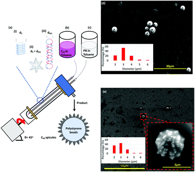
Spheroidal like fullerene C60 comprised of sp2 carbon atoms arranged at the vertices of a truncated icosahedron 1 nm in diameter1 can self-assemble into a variety of nano-structures, including rods, prisms, cones, spikes and vesicles.1–4 Such structures, depending on their size and morphology, have a variety of applications including in photodetectors, sensors, solar cells, light emitting diodes and drug delivery.2,5 In addition, chemically modified fullerene C60 has application for controlled slow release of encapsulated drugs.6 Recently, we established the use of the vortex fluidic device (VFD), Fig. 1, which is a thin film microfluidic platform, to control the self-assembly of the fullerene into rods, spicules,7 cones8 and tubules,9 along with spheroidal entrapment of nano-meter size particles of self-assembled C60 by graphene, generated from graphite as an in situ process.10 Understanding the mechanism of formation of the self-assembled structures, depending on the choice of rotational speed, solvent or mixtures of solvents, uniquely formed at a tilt angle of 45°, has been made possible by linking the outcome of a number of other materials processing in the device, along with determining the spatial arrangement of holes formed in thin films of polysulfone (PSF) coating the inner surface of the tube, and the so called signature of a liquid.7 The latter is the sum of the effects of the change in temperature, film thickness and mixing time as a function of rotational speed, ω.7 These collective studies established three different types of topological fluid flow in the VFD for a 20 mm OD (17.5 mm ID) quartz tube with a hemispherical base (and similarly for a 10 mm OD tube), Fig. 1(a), namely (i) Coriolis circular flow (diameter = dC) from the hemispherical base of the tube, (ii) double helical flow (diameter = dDH) arising from eddies generated by the Faraday waves combined with the Coriolis from the curvature along the tube, and (iii) spicular or spheroidal flow arising from the collapse of circular and double helical flow of the same diameter (dC = dDH), Fig. 1. The signature of toluene established a region of circular flow at ca. 3k rpm, transitioning to spicular flow at 3.8k rpm, then double helical flow >6k rpm. When toluene solutions of C60 significantly below their saturation level are processed in the VFD, shear stress induced crystallisation prevails, affording spicules at 4k rpm, rods >6k rpm, and a mixture of rods and spicules at 6k rpm. These structures define the topological fluid flow at these speeds, noting that in the absence of shear stress, the nanoparticles slowly redissolve in toluene, back to thermodynamic equilibrium.7
 | ||
Fig. 1 Schematic illustration of the processing in the VFD and the associated topological fluid flows, (a), using a 1![[thin space (1/6-em)]](https://www.rsc.org/images/entities/char_2009.gif) : :![[thin space (1/6-em)]](https://www.rsc.org/images/entities/char_2009.gif) 1 mixture of a solution of C60 dissolved in toluene, (b), and a dispersion of poly(styrene-co-divinylbenzene) beads (PB) in toluene, (c). Scanning electron microscopy (SEM) images of the as-received beads processed in the absence of C60, with a statistical analysis of particle size (2–6 μm), (d), and coated beads formed at ω 4k rpm, flow rate 1 mixture of a solution of C60 dissolved in toluene, (b), and a dispersion of poly(styrene-co-divinylbenzene) beads (PB) in toluene, (c). Scanning electron microscopy (SEM) images of the as-received beads processed in the absence of C60, with a statistical analysis of particle size (2–6 μm), (d), and coated beads formed at ω 4k rpm, flow rate  0.1 mL min−1, θ = 45°, concentrations of C60 and poly(styrene-co-divinylbenzene) in toluene 0.1 mg mL−1 with a zoomed in SEM image inset along with a statistical size distribution (2–6 μm), (e); SEM images were for samples prepared by drop-casting onto the surface of a silicon wafer. The different topological fluid flows, (a), for toluene in a 20 mm OD (17.5 mm ID) VFD tube, (i) Coriolis flow for ω >3k rpm, (ii) spicular flow for ω ca. 4k rpm and (iii) double helical flow for ω >ca. 6k rpm.7 0.1 mL min−1, θ = 45°, concentrations of C60 and poly(styrene-co-divinylbenzene) in toluene 0.1 mg mL−1 with a zoomed in SEM image inset along with a statistical size distribution (2–6 μm), (e); SEM images were for samples prepared by drop-casting onto the surface of a silicon wafer. The different topological fluid flows, (a), for toluene in a 20 mm OD (17.5 mm ID) VFD tube, (i) Coriolis flow for ω >3k rpm, (ii) spicular flow for ω ca. 4k rpm and (iii) double helical flow for ω >ca. 6k rpm.7 | ||
Under spheroidal spicular topological flow, hereafter referred to as spicular flow, graphene oxide collapses into spheroidal structures, reversibly forming scrolls under circular flow, and flat sheets for double helical flow.7 Spicular flow essentially provides a non-directional shear stress environment, and we deemed that this topological fluid flow is important in being able to control the shear stress environment for selectively coating particles and manipulating microorganisms. We hypothesised that spherical like particles in the dynamic thin film in the VFD could be shrouded by spicular topological fluid flow, depending on the diameter of the particles. To this end, we selected micron sized poly(styrene-co-divinylbenzene) beads as the particles of choice for determining the ability to coat them with fullerene C60 spicules under the aforementioned shear stress induced crystallisation processing.7 Poly(styrene-co-divinylbenzene) beads themselves find extensive use in a number of applications which are likely to be also relevant in the present and future studies, for example, in chromatography catalysis and cation exchange membranes.11,12 The present work is also of importance in further developing the utility of the VFD noting that it has a growing number and diversity of applications, including in controlling chemical reactivity and selectivity, protein folding, enhancing enzymatic reactions and separating proteins,13–15 and in materials processing. VFD-mediated material processing, beyond the above, include exfoliation of graphene from graphite and the manipulation of other 2D materials,10,16 creating toroidal structures of self-assembled single walled carbon nanotubes,17,18 and slicing single and multi-walled carbon tubes.19
In systematically exploring the operating parameters of the VFD while taking into account the fluid dynamic response of toluene in the VFD, as defined by its signature,7 we were able to coat spicules of C60ca. 150 nm in length, and ≥ca. 100 nm in diameter, over the surface of poly (styrene-co-divinylbenzene) beads ca. 2–6 μm in diameter, Fig. 1. Toluene solutions of C60 were initially prepared by adding as-received C60 to the solvent with the mixture allowed to stand overnight at room temperature, whereupon it was decanted to separate any residue. The concentration of C60 was then adjusted prior to the solution being delivered to the hemispherical base of the rapidly rotating quartz tube in the VFD through a jet feed, with a suspension of polystyrene beads in toluene (0.1 mg mL−1) delivered also at the base of the tube through a second jet feed, using separate syringe pumps, Fig. 1. The choice of concentration of polystyrene beads was based on the concentration of C60 used for fabricating spicules of the fullerene in the absence of styrene beads,7 with higher concentrations potentially disturbing the topological fluid flow.
In a 20 mm OD tube in the VFD, toluene has primarily spicular or spheroidal like topological fluid flow at ω ca. 4k rpm, whereas it is dominated by double helical flow for ω ≥6k rpm.7 Prior to continuous flow processing in the VFD, we used the confined mode of operation where a finite amount of liquid (≤2 mL) was processed with the tube rotating at 4k or 7.5k rpm, with the concentration of C60 and polystyrene beads then varied. However, there was minimal coating of the polystyrene beads with C60 at both rotational speeds; at 4k rpm for 0.1 mg mL−1 concentrations of both materials, Fig. S5 (ESI†), there are some C60 particles adhering to the isolated beads post VFD processing. Following this we moved to continuous flow operation of the VFD with the liquids introduced through jet feeds as discussed above. Here the flow rate  was controlled using syringe pumps, noting that 0.1 mL min−1 is effective in generating spicules of fullerene C60 in the absence of polystyrene beads when the tube is rotating at 4k rpm, and tilted at 45° (θ).7 Now in the presence of such beads, using the same operating parameters and concentrations, coating of the beads with spicules of C60 was effective, for beads ca. 2–6 μm in diameter, Fig. 1. Of note is that any nanomaterials of C60 formed in the VFD in toluene arising from the induced shear stress crystallisation will redissolve slowly back to thermodynamic equilibrium, but with enough time for isolating them.7 Given that C60 solubilization in toluene is inherently slow and that the structures obtained in the VFD are uniform is size and shape with no eroded features,7 any flow induced breakup phenomena would be minimal.22 The coating of the polystyrene beads with C60 at the optimised conditions is in high yield (>98%), with a 1
![[thin space (1/6-em)]](https://www.rsc.org/images/entities/char_2009.gif) :
:![[thin space (1/6-em)]](https://www.rsc.org/images/entities/char_2009.gif) 1 ratio of polystyrene and C60 having all the beads coated and without the formation of spicules devoid of the beads. Minor components of partially coated and/or fused beads also coated with C60 were observed, Fig. S4 (ESI†).
1 ratio of polystyrene and C60 having all the beads coated and without the formation of spicules devoid of the beads. Minor components of partially coated and/or fused beads also coated with C60 were observed, Fig. S4 (ESI†).
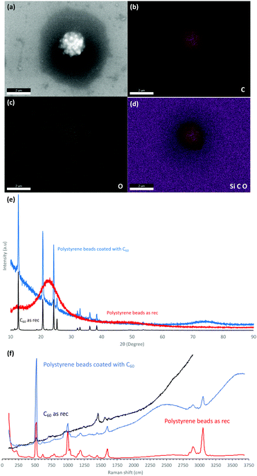
The dimensions of the particles and properties were studied using scanning electron microscopy (SEM), energy-dispersive X-ray spectroscopy (EDX), X-ray diffraction (XRD), thermo-gravimetric analysis (TGA) and Raman spectroscopy (532 nm excitation wavelength). SEM was used to ascertain the size and shape of the material, as shown for the spherical spikes, Fig. 1. EDX revealed the material is essentially carbon with some surface oxidation, Fig. 2c. The Raman spectra showed the vibrational signature modes for the polystyrene beads (531, 980, 1200, 1603, 2911 and 3050 cm−1), and a broad fluorescence peak akin to the presence of C60, Fig. 2f.20 Interestingly, optical microscopy revealed that even when using the low laser power (<0.01 mW) in the Raman studies, the spicules are damaged during the spectroscopic studies.
The XRD data for the coated beads and as received C60 powder are in agreement with the database for the fcc phase of the fullerene, with the major peaks at 10.8°, 17.7°, and 20.8° corresponding to the (111), (220), and (311) planes respectively.21 However, the peaks are broad in the coated beads with the Scherrer equation giving an average crystal domain size of 28 nm. The presence of small domains is consistent with other structures of self-assembled C60 generated in the VFD, including cones ca. 1 μm in diameter, where the domains are 6.5 nm in diameter.8 In addition, spicules of C60 formed in the absence of polystyrene beads, or in the presence of beads which are too large for the topological fluid flow to coat them (see below), domains are also present, 6.5 nm8 and 27.1 nm in diameter, Fig. 2, respectively.
The presence of nm size domains in the shear stress induced crystallised C60 supports a two-step mechanism of growth, i.e. the generation of nanoparticles as the primary process, followed by their self-assembly into the different structures, depending on the topological fluid flow and the choice of solvent system, noting that cones are formed from shear stress generated in double helical flow, whereas for the spicules and spicule coated polystyrene beads, the fluid flow is a combination of this with the circular Coriolis flow from the hemispherical base of the rotating tube.7 The shear stress in the VFD is not uniform in the thin film of liquid but rather it can be uniformly located.7 The induced crystallization of C60, in coating polystyrene beads or in forming free standing material, is in accord with theoretical predicted shear driven aggregation of colloidal systems.23
Thermal gravitational analysis (TGA) under nitrogen was recorded for the C60 coated beads (stored for one week at room temperature) and compared with the as-received beads (ca. 2–6 μm). The latter revealed a 95% weight loss between 300 °C and 440 °C, Fig. S7a (ESI†). The TGA profile for the composite material was dramatically different, with an increase in weight at ca. 120 °C, which corresponds to oxidation of fullerene C60, followed by a sharp weight loss at ca. 380 °C, although this is now less pronounced for increasing temperatures. Coating the C60 spicules on the surface of the beads increases the decomposing temperature profile. This is consistent with the coating of the polystyrene beads with C60 ‘shielding’ the polystyrene beads from the heat generated during the TGA.24,25
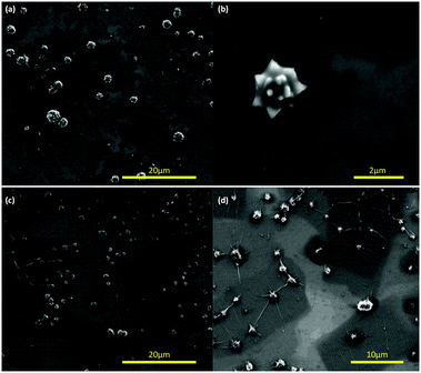
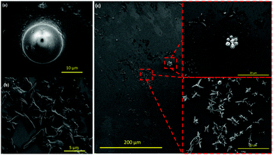
To ascertain the effect of the choice of operating parameters of the VFD for coating the polystyrene beads, and the importance of the associated topological fluid flows, we altered the tilt angle from +45° to +40 and +50° for beads 2 to 6 μm in diameter. For the lower tilt angle, there is more agglomeration of the beads but nevertheless they are coated with spicules, Fig. 3(a and b). This also prevails for the higher tilt angle but with fibres connecting some of the beads indicating more complex fluid flow, Fig. 3(c and d). We then fixed the tilt angle at 45° and used larger polystyrene beads, ca. 14–20 μm in diameter, with the other VFD operating parameters the same as for optimal coating of the smaller breads, Fig. 1. Here there was no evidence for coating the beads, being unperturbed relative to the as received beads, with the C60 forming spicules comprised only of the fullerene, Fig. 4(a and b), as if the beads were not present.7 Thus there is a limit on the size of the beads that can be coated in a 20 mm OD diameter VFD tube, i.e. there is an upper limit on the ability for the spheroidal topological fluid flow to be able to accommodate a particle within its confines.
 | ||
| Fig. 3 SEM images of the composite material of C60 and polystyrene beads drop casted onto the surface of a silicon wafer with the beads formed using the same processing conditions as in Fig. 1 but with the tilt angle θ set at (a and b) 40°, and (c and d) 50°. | ||
 | ||
| Fig. 4 SEM images (a and b) of the uncoated polystyrene beads (ca. 14–20 μm in diameter) and spicules of C60 devoid of a polystyrene core, formed under the optimised conditions for coating 2–6 μm beads, Fig. 1. (c) Uncoated polystyrene beads (ca. 2–6 μm diameter) along with spicules of C60 devoid of a polystyrene core formed under the optimised conditions, Fig. 1, but now using a 10 mm OD VFD. | ||
The diameter of the tube in the VFD can be varied and this processing option has been used in materials processing.7,16 In testing the effect of the choice of diameter on the nature of the product herein, we explored the possibility of coating polystyrene beads in a 10 mm OD tube. This is the original diameter of the tube used in developing the VFD.13 Reducing the diameter of the tube reduces the diameter of the topological fluid flow in the VFD.7 Translating the optimised conditions in Fig. 1 for a 20 mm OD tube for 2–6 μm beads to a 10 mm OD tube for the same beads resulted in the formation of spicules of C60 devoid of a polystyrene core, the beads being devoid of surface bound spicules, Fig. 4(c). Thus, the spicular fluid flow in the 10 mm OD (7.5 mm ID) tube is too small to accommodate polystyrene beads ca. 2–6 μm in diameter.
In conclusion, we report a simple and effective method for fabricating fullerene C60 spicules over the surface of spherical poly(styrene-co-divinylbenzene) beads under continuous flow mode of operation of the VFD, and that there is an upper limit of the size of the beads that can be confined within the spheroidal topological fluid flow, ≥ca. 6 μm. The structures of the spheroidal composite material are uniform in shape, and importantly the isolated yield of the product is high (>98%), with the processing scalable under continuous flow conditions. The ability to selectively coat a certain diameter particle lends itself for size specific surface modification for applications in materials processing, and also in the coating of small molecule drugs, nanoparticles, and macromolecules over the surface of micron sized particles that can be accommodated in the spheroidal topological fluid flow. Further development of this processing to control the thickness of any coating is also important for specific applications.
Matt Jellicoe thanks Flinders University for scholarship funding, and the authors gratefully acknowledge financial support from the Australian Research Council. The authors acknowledge the expertise, equipment and support provided by Microscopy Australia (MA) and the Australian National Fabrication Facility (ANFF) at the South Australian nodes under the National Collaborative Research Infrastructure Strategy.
Conflicts of interest
There are no conflicts to declare.Notes and references
- M. Prato, J. Mater. Chem., 1997, 7, 1097–1109 RSC.
- M. Sathish, K. i. Miyazawa, J. P. Hill and K. Ariga, J. Am. Chem. Soc., 2009, 131, 6372–6373 CrossRef CAS.
- M.-S. Lin, R.-T. Chen, N.-Y. Yu, L.-C. Sun, Y. Liu, C.-H. Cui, S.-Y. Xie, R.-B. Huang and L.-S. Zheng, Colloids Surf., B, 2017, 159, 613–619 CrossRef CAS.
- T. Konno, T. Wakahara and K. I. Miyazawa, J. Cryst. Growth, 2015, 416, 41–46 CrossRef CAS.
- K. i. Miyazawa, J.-i. Minato, T. Yoshii and T. Suga, Sci. Technol. Adv. Mater., 2005, 6, 388–393 CrossRef CAS.
- K. Ariga, Q. Ji, J. P. Hill, Y. Bando and M. Aono, NPG Asia Mater., 2012, 4, e17 CrossRef.
- T. M. D. Alharbi, et al. , n.d. DOI:10.26434/chemrxiv.13141352.v1.
- I. K. Alsulami, T. M. D. Alharbi, D. P. Harvey, C. T. Gibson and C. L. Raston, Chem. Commun., 2018, 54, 7896–7899 RSC.
- K. Vimalanathan, R. G. Shrestha, Z. Zhang, J. Zou, T. Nakayama and C. L. Raston, Angew. Chem., Int. Ed., 2017, 56, 8398–8401 CrossRef CAS PubMed.
- X. Chen, J. F. Dobson and C. L. Raston, Chem. Commun., 2012, 48, 3703–3705 RSC.
- Q. C. Wang, F. Švec and J. M. J. Fréchet, J. Chromatogr. A, 1994, 669, 230–235 CrossRef CAS PubMed.
- S. Savari, S. Sachdeva and A. Kumar, J. Membr. Sci., 2008, 310, 246–261 CrossRef CAS.
- L. Yasmin, X. Chen, K. A. Stubbs and C. L. Raston, Sci. Rep., 2013, 3, 2282 CrossRef PubMed.
- J. Britton, R. P. Dyer, S. Majumdar, C. L. Raston and G. A. Weiss, Angew. Chem., Int. Ed., 2017, 56, 2296–2301 CrossRef CAS PubMed.
- J. Britton, L. M. Meneghini, C. L. Raston and G. A. Weiss, Angew. Chem., Int. Ed., 2016, 55, 11387–11391 CrossRef CAS PubMed.
- A. H. M. Al-antaki, T. M. D. Alharbi, S. Kellici, N. P. Power, W. Lawrance and C. L. Raston, ChemNanoMat, 2020, 6, 657–662 CrossRef CAS.
- K. Vimalanathan, X. Chen and C. L. Raston, Chem. Commun., 2014, 50, 11295–11298 RSC.
- T. M. D. Alharbi, Y. Shingaya, K. Vimalanathan, T. Nakayama and C. L. Raston, ACS Appl. Nano Mater., 2019, 2, 5282–5289 CrossRef CAS.
- K. Vimalanathan, J. R. Gascooke, I. Suarez-Martinez, N. A. Marks, H. Kumari, C. J. Garvey, J. L. Atwood, W. D. Lawrance and C. L. Raston, Sci. Rep., 2016, 6, 22865 CrossRef CAS PubMed.
- T. Shimada, Y. Yamamoto, T. Kaji, K. Itaka, H. Koinuma, Y. Kuninobu, Y. Matsuo, E. Nakamura and K. Saiki, Solid State Commun., 2004, 132, 197–201 CrossRef CAS.
- K. Miyazawa, Y. Kuwasaki, A. Obayashi and M. Kuwabara, J. Mater. Res., 2002, 17, 83–88 CrossRef CAS.
- F. Mura and A. Zaccone, Phys. Rev. E, 2016, 93, 042803 CrossRef PubMed.
- A. Zaccone, H. Wu, D. Gentilli and M. Morbibelli, Phys. Rev. E: Stat., Nonlinear, Soft Matter Phys., 2009, 80, 051404 CrossRef PubMed.
- I. K. Alsulam, T. M. D. Alharbi, M. Moussa and C. L. Raston, ACS Omega, 2019, 4, 19279–19286 CrossRef CAS PubMed.
- F.-A. Teng, Y. Guo, H. Jianping, Y. Zhang and Z. Han, Des. Monomers Polym., 2017, 20, 283–292 CrossRef CAS PubMed.
Footnote |
| † Electronic supplementary information (ESI) available. See DOI: 10.1039/d0cc07165j |
| This journal is © The Royal Society of Chemistry 2021 |


