
 Open Access Article
 This Open Access Article is licensed under a Creative Commons Attribution-Non Commercial 3.0 Unported Licence
Extrusion-based 3D printed magnesium scaffolds with multifunctional MgF2 and MgF2–CaP coatings†
J.
Dong
 *a,
N.
Tümer
a,
N. E.
Putra
a,
J.
Zhu
b,
Y.
Li
c,
M. A.
Leeflang
a,
P.
Taheri
b,
L. E.
Fratila-Apachitei
a,
J. M. C.
Mol
b,
A. A.
Zadpoor
a and
J.
Zhou
a
*a,
N.
Tümer
a,
N. E.
Putra
a,
J.
Zhu
b,
Y.
Li
c,
M. A.
Leeflang
a,
P.
Taheri
b,
L. E.
Fratila-Apachitei
a,
J. M. C.
Mol
b,
A. A.
Zadpoor
a and
J.
Zhou
a
aDepartment of Biomechanical Engineering, Delft University of Technology, Delft 2628 CD, The Netherlands. E-mail: J.Dong-5@tudelft.nl; Tel: +31-68-5007285
bDepartment of Materials Science and Engineering, Delft University of Technology, Delft 2628 CD, The Netherlands
cBeijing Advanced Innovation Center for Materials Genome Engineering, School of Materials Science and Engineering, University of Science and Technology Beijing, 30 Xueyuan Road, Haidian District, Beijing 100083, China
First published on 1st September 2021
Abstract
Additively manufactured (AM) biodegradable magnesium (Mg) scaffolds with precisely controlled and fully interconnected porous structures offer unprecedented potential as temporary bone substitutes and for bone regeneration in critical-sized bone defects. However, current attempts to apply AM techniques, mainly powder bed fusion AM, for the preparation of Mg scaffolds, have encountered some crucial difficulties related to safety in AM operations and severe oxidation during AM processes. To avoid these difficulties, extrusion-based 3D printing has been recently developed to prepare porous Mg scaffolds with highly interconnected structures. However, limited bioactivity and a too high rate of biodegradation remain the major challenges that need to be addressed. Here, we present a new generation of extrusion-based 3D printed porous Mg scaffolds that are coated with MgF2 and MgF2–CaP to improve their corrosion resistance and biocompatibility, thereby bringing the AM scaffolds closer to meeting the clinical requirements for bone substitutes. The mechanical properties, in vitro biodegradation behavior, electrochemical response, and biocompatibility of the 3D printed Mg scaffolds with a macroporosity of 55% and a strut density of 92% were evaluated. Furthermore, comparisons were made between the bare scaffolds and the scaffolds with coatings. The coating not only covered the struts but also infiltrated the struts through micropores, resulting in decreases in both macro- and micro-porosity. The bare Mg scaffolds exhibited poor corrosion resistance due to the highly interconnected porous structure, while the MgF2–CaP coatings remarkably improved the corrosion resistance, lowering the biodegradation rate of the scaffolds down to 0.2 mm y−1. The compressive mechanical properties of the bare and coated Mg scaffolds before and during in vitro immersion tests for up to 7 days were both in the range of the values reported for the trabecular bone. Moreover, direct culture of MC3T3-E1 preosteoblasts on the coated Mg scaffolds confirmed their good biocompatibility. Overall, this study clearly demonstrated the great potential of MgF2–CaP coated porous Mg prepared by extrusion-based 3D printing for further development as a bone substitute.
1. Introduction
The treatment of critical-sized bone defects remains a challenge. Current clinically available bone substitutes have serious limitations, cannot meet all clinical requirements, and are limited in supply.1 In choosing implants for orthopedic treatments and developing a new generation of bone implants, both the material and structure must be critically considered. An ideal material for bone implants should be biodegradable, mechanically stable while its biomechanical function is needed, biocompatible, and osteogenic.2,3 Porous structures are preferred for bone regeneration, since interconnected pore networks permit nutrients to be transferred and waste to be taken away, which is conducive to cell proliferation and differentiation and promotes tissue regeneration.4In recent years, Mg and its alloys have been intensively developed as a new class of biodegradable materials for orthopedic implants. Interest in Mg is due to several reasons. First, Mg and its alloys possess densities (1.74–2.0 g cm−3) and elastic moduli (41–45 GPa) close to those of human bones (1.8–2.1 g cm−3 and 3–20 GPa, respectively).5 Second, Mg ions are essential for the human body, playing an important role in bone health.6 Third, Mg ions released from biodegradable Mg implants can stimulate angiogenesis7 and induce new bone regeneration.8 In particular, considerable attention has been paid to porous Mg scaffolds, as they are seen as highly promising candidates to serve as suitable bone substitutes that can meet all of the requirements mentioned above for bone implants.
Recent advances in additive manufacturing (AM) have prompted its application to prepare porous Mg scaffolds with precisely controlled structures. While powder bed fusion AM techniques have been the most commonly investigated ones for Mg scaffold fabrication,9–17 success has so far been limited.18–20 This is mainly because some crucial issues related to safety in AM operations, undesirable compositional variations due to Mg evaporation, and severe oxidation during the AM process cannot be fully resolved.10,21 Therefore, researchers have made tremendous efforts to search for viable alternative techniques for the AM of porous Mg.22,23 Recently, the extrusion-based AM technique has been successfully applied to prepare porous Mg scaffolds.24 With this technique, Mg scaffolds can be printed at room temperature by extruding a Mg powder loaded ink with a designed porous structure, followed by debinding and sintering to decompose the binder present in the ink and consolidate the remaining Mg powder. This technique can, indeed, avoid the difficulties that have been encountered in applying powder bed fusion AM for preparing Mg scaffolds. Moreover, unlike powder bed fusion AM, extrusion-based AM is capable of delivering hierarchically interconnected porous Mg scaffolds that can only be achieved through a template-replicating method25,26 and facilitate cell adhesion, proliferation, migration and differentiation.27
Pure Mg was chosen for our first attempt at making the material system simple.24 However, in general, pure Mg exhibits a relatively high biodegradation rate,28–30 which can cause premature implant failure and the generation of a large amount of hydrogen gas, triggering acute and unfavorable inflammatory responses. The large surface area of porous Mg exposed to physiological media accelerates biodegradation further. The high rate of biodegradation also leads to a high rate of ion release, which negatively affects the cytocompatibility of porous Mg. Slowing down the biodegradation process is therefore of paramount importance and thus the focus of the present research. Surface modification is a well-known technology to improve the corrosion resistance of Mg,31i.e., to reduce its biodegradation rate. To date, various surface modification methods have been developed for Mg.32 However, ensuring the consistent quality of coatings on strut surfaces with micropores in a 3D porous structure remains a challenge due to the geometric complexities of the surfaces and the porous structure as a whole.33 The highly porous structure of the prepared scaffolds must be taken into consideration, when it comes to the choice of methods suitable for surface modification. For porous structures, the chemical conversion method is usually preferred, since the chemical reaction between the Mg substrate and chemical conversion solution during the coating procedure permits any exposed Mg surfaces to be uniformly coated. Among various conversion coatings, fluoride conversion coating is one of the most effective methods for porous Mg-based materials, since it has been found that a MgF2 coating layer can, indeed, form on the entire surface of the struts of porous Mg,26,34,35 although the pore sizes of the scaffolds used in those studies (150–400 μm) are much larger than the sizes of the micropores that were present in the struts of the scaffolds prepared earlier (10–100 μm).24 In addition to improving corrosion resistance, the MgF2 coating has other advantages of strongly adhering to the Mg substrate and demonstrating good biocompatibility.36,37 However, the MgF2 coating has a limited osteogenic ability.26 To overcome this limitation, an additional coating consisting of calcium phosphate (CaP) compounds may be superimposed, considering that their osteoconductive ability is essential for bone regeneration and maturation through promoting osteoblast proliferation.38,39 The combination of both fluoride and CaP coatings with MgF2 as an interlayer on bulk Mg-based materials has, indeed, turned out to be advantageous for orthopedic applications.40,41 However, there is as yet no information available in the literature regarding the applicability of MgF2–CaP coatings to geometrically ordered and hierarchically porous Mg scaffolds, although such coatings have been applied to solid magnesium and Mg alloy samples and demonstrated the expected benefits.
Here, we prepared porous Mg scaffolds using the extrusion-based AM technique and applied MgF2 single-layer coating and MgF2–CaP double-layer coatings to the scaffolds. We evaluated the mechanical properties, biodegradation behavior, and biocompatibility of bare and coated Mg scaffolds. By proving the feasibility of applying multifunctional coatings on Mg scaffolds and the resulting enhanced corrosion resistance and surface biocompatibility, we intended to bring the AM Mg scaffolds closer to their application as a suitable bone substitute.
2. Materials and methods
2.1 Scaffold manufacturing
Pure Mg powder (impurity <0.01%) with a median particle size of 44.96 μm (Tangshan Weihao Magnesium Powder Co. Ltd, China) was used as the starting material. A Mg powder loaded ink was prepared by manually mixing 50 vol% Mg powder particles with a binder system composed of hexane and polyisobutylene polymer (Mw ∼ 500![[thin space (1/6-em)]](https://www.rsc.org/images/entities/char_2009.gif) 000, Sigma Aldrich, Germany). The ink was loaded into a syringe (EFD, Nordson, Germany) mounted on a 3D Bioscaffolder printer (BS 3.2, GeSim, Germany).
000, Sigma Aldrich, Germany). The ink was loaded into a syringe (EFD, Nordson, Germany) mounted on a 3D Bioscaffolder printer (BS 3.2, GeSim, Germany).
A cylindrical porous architecture with a lay-down pattern of 0°/90°/0° was designed using the GeSim custom software (Fig. 1a). A linear infill pattern with a strut size of 580 μm and a spacing distance of 360 μm was adopted (Fig. 1b), resulting in a density of 62.2% (calculated by SolidWorks) or a macro-porosity of 37.8%.
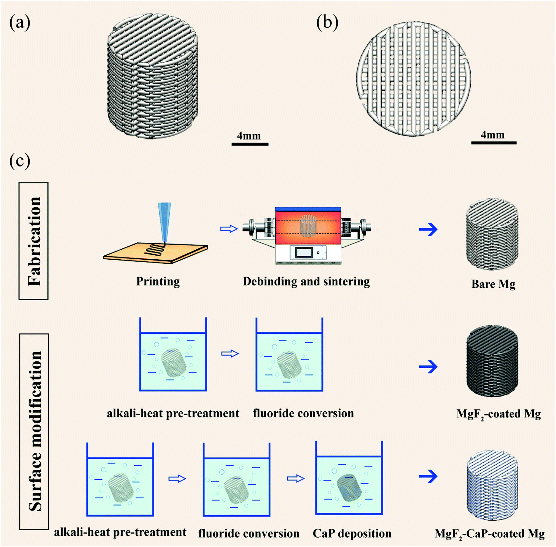 | ||
| Fig. 1 Design of the porous Mg scaffold (a and b) and schematic illustrations of the steps for scaffold fabrication and then surface modification (c). | ||
The Mg scaffolds were then printed using the Bioscaffolder printer by extruding the prepared ink under an applied pressure of 140–160 kPa and at a printing speed of 5 mm s−1. The printed scaffolds were then subjected to debinding and sintering, which was conducted in a tube furnace (Carbolite Gero, Germany) under a controlled atmosphere of argon (purity ≥99.9999%). The printed scaffolds were heated at a rate of 5 °C min−1 from room temperature to 640 °C with a dwelling time of 1 h, followed by furnace cooling to room temperature. These prepared scaffolds are hereafter referred to as “bare Mg”.
2.2 Surface modification
2.3 Microstructural characterization
Mg powder embedded in an epoxy resin and the prepared Mg scaffold struts were ground, polished, and etched in a solution composed of nitric acid, acetic acid, water, and ethanol at a volume ratio of 1:3:4:12. After etching, the microstructure of Mg powder was observed using an optical microscope (OM, VH-Z250R, Keyence Corp., USA), while that of the prepared Mg scaffold struts was observed under a scanning electron microscope (SEM, JSM-IT100, JEOL, Japan). The average grain size was determined by using the line intercept method.
2.4 Porosity characterization
The porosity of the as-printed Mg scaffolds was calculated using the weighing method, based on the equation: | (1) |
The porosities of the bare, MgF2-coated, and MgF2–CaP-coated Mg scaffolds were determined in three ways. First, a simple weighing method was adopted, based on the following equation:
 | (2) |
Second, X-ray micro-computed tomography (μCT, Nanotom 180 NF, GE Phoenix) with a resolution of 6 μm was used to scan the Mg scaffolds. Dicom images of the scanned samples were exported to Dragonfly (Object Research Systems, Canada) after reconstruction. Suitable thresholding was applied to segment each sample. The “bone volume” corresponding to the volume of the scaffold sample and “total volume” corresponding to the bulk volume of the scaffold sample were measured by using the plugin “bone analysis” in the same software. The absolute porosity was obtained according to the equation:
 | (3) |
Third, the interconnected porosity and pore size distribution were measured by means of mercury intrusion porosimetry (MIP, Micromeritics Autopore IV 9500) at pressures over the range of 0 to 210 MPa. Pore interconnectivity was quantified using the following equation:
 | (4) |
2.5 Characterization of surface-modified scaffold struts
The morphologies and cross-section microstructures of the bare, MgF2-coated, and MgF2–CaP-coated Mg scaffolds at the periphery and at the center were examined using a scanning electron microscope (SEM, JSM-IT100, JEOL, Japan) equipped with energy-dispersive X-ray spectroscopy (EDS). The microporosities of the bare and coated Mg scaffolds, the layer thicknesses of MgF2 and MgF2–CaP coatings, and the volume fractions of the Mg matrix, the coatings, and the compounds formed inside micropores were measured from the SEM images of the polished cross sections using ImageJ software (National Institutes of Health, USA). The phase identification of the scaffolds was performed using an X-ray diffractometer (XRD, Bruker D8 Advance diffractometer in the Bragg–Brentano geometry). The diffractometer was equipped with a Lynxeye position sensitive detector and was operated at 45 kV and 40 mA over a scan range of 20–100° and at a step size of 0.030° using Cu Kα radiation. In addition, Fourier-transform infrared spectroscopy (FTIR) spectra were obtained using a Thermo-Nicolet Nexus FTIR apparatus equipped with a liquid-nitrogen cooled MCT-A (mercury–cadmium–telluride) detector and a SAGA grazing angle accessory at an incident angle of 80°. An infrared background spectrum was collected on the bare Mg scaffolds before collecting the final spectra of the MgF2-coated and MgF2–CaP coated Mg scaffolds with the setting of 128 scans at a resolution of 2 cm−1.2.6 In vitro degradation behavior
 | (5) |
The morphologies and cross-section microstructures of the Mg scaffolds at the periphery and at the center after the immersion tests at selected time points were observed under the SEM (JSM-IT100, JEOL, Japan). The compositions of the degradation products formed on the scaffolds were analyzed using EDS, while the phase identification was made based on analysis by XRD (Bruker D8 Advance diffractometer in the Bragg–Brentano geometry). The FTIR spectra of the degraded bare, MgF2-coated, and MgF2–CaP-coated porous Mg specimens were obtained upon subtraction of those recorded before biodegradation as the background.
 | (6) |
The LPR tests were conducted at different exposure times up to 3 days from −25 mV to +25 mV versus OCP at a scan rate of 0.167 mV s−1 (after 3 days, the electrolyte penetrated into the trench between the resin and embedded Mg scaffolds due to degradation of the scaffolds, resulting in unreliable results).
2.7 Mechanical properties
Uniaxial compression tests on the as-prepared bare Mg, MgF2-coated Mg and MgF2–CaP-coated Mg scaffolds, as well as the MgF2-coated and MgF2–CaP-coated scaffold specimens retrieved after 1, 3, and 7 days of in vitro immersion, were performed using a Lloyd machine (LR5K, 5 kN load cell) at a crosshead speed of 2 mm min−1. The Young's moduli and yield strengths of the tested specimens were determined according to ISO 13314: 2011. The Young's modulus was determined from the slope of the initial linear region of the obtained stress–strain curve and the yield strength was determined from the intersection between the curve and the parallel line at 0.2% offset to the linear region. Beyond this point, permanent deformation occurred, as well as work hardening and more importantly the densification of the porous structure, leading to increases in stress. Considering the requirement for bone implants to provide mechanical support while maintaining an interconnected porous structure, stresses beyond the yield stress were considered to be of less interest.2.8 Biocompatibility evaluation
The extract culture media were prepared by immersing bare, MgF2-coated, and MgF2–CaP-coated Mg scaffold samples (9.54 mm in diameter and 4.85 mm in height) in the α-MEM (without ascorbic acid, but with 10% FBS, 1% p s−1) under the abovementioned physiological conditions for 72 h.46 The ratio of surface area of the sample to the volume of the medium was 1.25 cm2 mL−1, according to the EN ISO standards 10993-12.47 The supernatant was then collected, filtered, and diluted to 100%, 50% and 10% with α-MEM. The pH of these extracts was measured by using a pH-meter (METTLER TOLEDO) and the Mg ion concentrations in those extracts were measured using ICP-OES (iCAP 6500 Duo Thermo Fisher Scientific).
 | (7) |
Furthermore, actin staining was performed to observe the morphology of the cells cultured with the extracts. The MC3T3-E1 cells (5 × 10³ cells) were cultured for 7 days on 48-well glass disks in 200 μL of the extracts. The samples were washed with phosphate buffered saline (PBS, Sigma-Aldrich, Germany), fixed using 4% formaldehyde/PBS (Sigma-Aldrich, Germany) for 15 min at room temperature, and permeabilized with 0.5% Triton/PBS at 4 °C for 5 min. Afterwards, 1% bovine serum albumin (BSA)/PBS (Sigma-Aldrich, Germany) was added to each well, followed by 5 min of incubation, the addition of rhodamine phalloidin (1:1000 in 1% BSA/PBS, Life Technologies Corp., USA), and incubation at 37 °C for 1 h. The samples were then washed with 0.5% Tween/PBS (Sigma-Aldrich, Germany) three times prior to being mounted on glass slides with Prolong gold (containing 4′,6-diamidino-2-phenylindole (DAPI), Life Technologies, USA). The cytoskeleton and cell nuclei were examined using a fluorescence microscope (ZOE fluorescent cell imager, Bio-Rad Laboratories Inc., USA).
2.9. Statistical analysis
All experimental values are expressed as mean ± standard deviation. Statistical analysis of the metabolic activity results obtained from the indirect cytotoxicity tests was performed using ANOVA, followed by the Tukey post hoc test (α = 0.05) with p < 0.0001, ****; p < 0.001, ***; p < 0.01, **; p < 0.05, *; n.s. = not significant.3. Results
3.1 Geometrical characteristics of the as-sintered and as-coated scaffolds
The as-printed pure Mg scaffolds showed a geometrically ordered porous structure with accurate stacks of layers of struts, as designed, with an average strut width of 587.6 ± 11.7 μm and a strut spacing of 351.4 ± 18.5 μm (Fig. 2a). During subsequent sintering, the overall dimensions of the scaffolds shrank by 9.5 ± 0.2%. As a result, the as-sintered scaffolds had a reduced strut width of 528.1 ± 12.6 μm and a strut spacing of 298.4 ± 16.6 μm (Table 1). After fluoride conversion treatment, the MgF2-coated Mg scaffolds showed a brown surface with dimensions similar to the as-sintered ones, while the MgF2–CaP-coated Mg scaffolds had a rough, white surface with an increased average strut width of 562.1 ± 38.0 μm and a reduced strut spacing of 246.9 ± 21.7 μm (Fig. 2a and Table 1). | ||
| Fig. 2 Characteristics of the bare and coated Mg scaffolds: (a) macrographs, (b) porosities (weight-volume, Micro-CT and MIP analysis), (c) pore size distributions (MIP analysis), (d) microstructure of Mg powder, and (e) microstructure of the as-sintered Mg scaffolds. | ||
| Sample group | Height (mm) | Diameter (mm) | Strut width (μm) | Strut spacing (μm) | Absolute porosity (weight-volume) |
|---|---|---|---|---|---|
| Design | 12.64 | 12.38 | 580 | 360 | 37.8% |
| As-printed | 12.57 ± 0.05 | 12.13 ± 0.1 | 587.6 ± 11.7 | 351.4 ± 18.5 | 60.0 ± 1.9% |
| As-sintered bare Mg | 11.31 ± 0.27 | 10.92 ± 0.25 | 528.1 ± 12.6 | 298.4 ± 16.6 | 54.5 ± 2.4% |
| MgF2-coated Mg | 11.32 ± 0.42 | 10.97 ± 0.23 | 529.2 ± 15.7 | 294.2 ± 18.3 | 50.2 ± 1.3% |
| MgF2–CaP-coated Mg | 11.61 ± 0.33 | 11.24 ± 0.31 | 562.1 ± 38.0 | 246.9 ± 21.7 | 45.7 ± 1.2% |
The porosities measured using the weight-volume and μ-CT methods showed the same trend. Compared to the bare Mg scaffolds (around 55%), the absolute porosity of the MgF2-coated Mg scaffolds decreased (around 50%). After coating with MgF2–CaP, the absolute porosity of the scaffolds further decreased to around 45% (Fig. 2b). The MIP method was used to measure the interconnected porosities of the scaffolds. The coated scaffolds possessed less interconnected pores, compared with the bare Mg scaffolds. However, each of the three groups of Mg scaffolds still possessed a pore interconnectivity of above 80%. In addition, the pore size distribution determined by the MIP method showed a bimodal distribution of pore sizes in the bare and coated Mg scaffolds. Pores with sizes ranging between 100 and 400 μm corresponded to the macro-pores between the struts, defined in the scaffold design. The second peak in the pore diameter of the MgF2–CaP-coated Mg scaffolds decreased to around 200 μm, from those in the bare and MgF2-coated Mg scaffolds (around 300 μm) (Fig. 2c). Pores with sizes below 50 μm corresponded to micropores in the struts, which were the residual micropores after the debinding and sintering processes, and the volume of the micropores, as indicated by the first pore size peak, decreased significantly after surface modification (Fig. 2c).
The as-sintered Mg scaffolds had equiaxed grains and the grain size increased from 8.6 ± 1.7 μm in Mg powder to 26.9 ± 2.0 μm (Fig. 2d and e).
3.2 Morphological and structural characteristics of the as-sintered and as-coated scaffolds
 | ||
| Fig. 3 Characteristics of the MgF2 single-layer coating and MgF2–CaP double-layer coatings on the strut surfaces of the Mg scaffolds: (a–c) bare Mg scaffolds, (d–f) MgF2-coated Mg scaffolds, (g–i) MgF2–CaP-coated Mg scaffolds, (j) XRD patterns, and (k) FTIR spectra. | ||
XRD analysis confirmed the formation of MgF2 on MgF2-coated Mg scaffold struts. The detected CaP compound on MgF2–CaP-coated Mg scaffold struts was identified to be hydroxyapatite (HA) (Fig. 3j). In addition to the Mg matrix and HA, Mg(OH)2 was also detected in the MgF2–CaP-coated porous Mg. In the FTIR spectra of the MgF2-coated Mg specimens, the bands at 1641 cm−1 and 3420 cm−1 were attributed to the presence of residual water in the samples.48 However, the absorbance band of MgF2 cannot be detected, since its vibration is around 431 cm−1, which is beyond the range of the measurements.49 The bands at 1000–1200 cm−1 in the spectra of MgF2–CaP-coated porous Mg corresponded to the asymmetric stretching bending vibrations of the PO43− group in HA50 (Fig. 3k).
 | ||
| Fig. 4 SEM images (backscatter mode) of the cross-section of the struts of the bare and coated Mg scaffolds: (a) bare Mg, (b) MgF2-coated Mg at the periphery, (c) MgF2-coated Mg at the center, (d) MgF2–CaP-coated Mg at the periphery (the boxed areas show that the formation of CaP coating tended to flatten the uneven surfaces of the scaffolds), (e) MgF2–CaP-coated Mg at the center, (f and h) MgF2-coated Mg at the periphery at high magnification and corresponding EDS analysis (f-inset image: MgF2 coating on the surface at high magnification), and (g and i) MgF2–CaP-coated Mg at the periphery at high magnification and corresponding EDS analysis. | ||
| Sample | Microporosity | Mg matrix | Compounds inside micropores | Ca–P coating |
|---|---|---|---|---|
| Bare Mg | 8.5% ± 0.4% | 91.5% ± 0.4% | — | — |
| MgF2-coated Mg | 1.9% ± 0.2% | 86.3% ± 0.3% | 11.8% ± 0.2% | — |
| MgF2–CaP-coated Mg | 0.8% ± 0.6% | 77.0% ± 3.5% | 21.6% ± 3.8% | 0.6% ± 0.5% |
3.3 In vitro degradation behavior
 | ||
| Fig. 5 In vitro degradation behaviors of the three groups of the bare and coated Mg scaffolds: (a) visual inspection of degraded scaffolds, (b) pH variations with time, (c) volume losses at different time points, and (d) changes of the concentrations of ions in r-SBF with time. | ||
3.3.2.1 On struts. Four time points (i.e., 6 h and 1, 3 and 7 days) were selected for the examination of biodegradation products formed on the struts of the coated Mg scaffolds, while only 6 h and 1 day were selected for the bare Mg scaffolds (Fig. 6). Two kinds of biodegradation products were formed on the strut surfaces of the bare Mg scaffolds after 6 h immersion. The needle-shaped products contained Mg, O, C, and Cl (Fig. 6a, box 1), while the cracked flake-shaped compounds only contained Mg, O, and C (Fig. 6a, box 2). After 1 day of immersion, the flake-shaped compounds containing Mg and O (Fig. 6b, box 3) seemed to be loose. Regarding the MgF2-coated Mg scaffolds after in vitro biodegradation, the Mg powder particles were still clearly recognizable, with increased amounts of white deposition compounds from 6 h to 7 days of immersion (Fig. 6c–f). Interestingly, Ca was found after immersion only for 6 h, while P was detected for the first time at day 3 (Fig. 6d and e). Furthermore, the amount of F decreased with immersion time and it could no longer be detected at day 7 (Fig. 6f, box 4). After immersion, the MgF2–CaP coated Mg scaffolds were covered by a layer of dense corrosion products that contained O, C, Ca, and P without Mg until day 3 (Fig. 6g–i, boxes 1–3). At day 7, rose-like biodegradation products formed on the surface of the MgF2–CaP-coated scaffolds with the presence of Mg, O, and C, as well as low amounts of Ca and P (Fig. 6j, box 4).
 | ||
| Fig. 6 Surface morphologies and EDS analyses of the biodegradation products on the struts at different time points: (a and b) bare Mg, (c–f) MgF2-coated Mg, and (g–j) MgF2–CaP-coated Mg. | ||
To identify the composition of the corrosion products, XRD and FTIR were used to examine the surfaces of the biodegraded Mg scaffolds (Fig. 7). In addition to the α-Mg phase in the substrate, the XRD results revealed the presence of Mg3(OH)5Cl·4H2O and Mg(OH)2 on the surface of the bare Mg scaffolds after 6 h immersion, while only Mg(OH)2 was found at day 1 (Fig. 7a). The appearance of the peaks at 3700 cm−1 in the FTIR spectrum (Fig. 7b) could be attributed to the O–H stretching vibration in the crystal structure of Mg(OH)2.48 Furthermore, the bands between 750–900 cm−1 and 1440–1550 cm−1 likely resulted from CO32−51,52 (Fig. 7b). Regarding MgF2-coated Mg, only the α-Mg and MgF2 phases were found after 6 h of immersion, while Mg(OH)2 started to appear from day 1 onwards (Fig. 7c). Similar to bare Mg, FTIR revealed the possible presence of Mg(OH)2 and carbonates on the surface of biodegraded MgF2-coated Mg and the intensities of these biodegradation products increased with immersion time (Fig. 7d). Mg(OH)2 and HA were found on the strut surfaces of the MgF2–CaP-coated Mg scaffolds after 6 h immersion and dicalcium phosphate (DCP, CaHPO4) was first found at day 3 (Fig. 7e). The intensity of the peak corresponding to Mg(OH)2 suddenly increased at day 7, which was consistent with the result that the peak of OH− was stronger at day 7 in the FTIR spectrum of the MgF2–CaP-coated Mg scaffolds (Fig. 7f). The clearly visible absorption bands at 1160 and 1040 cm−1 that corresponded to phosphates appeared at all time points. Similarly, carbonate (1440–1550 cm−1) was found at all time points (Fig. 7f).
 | ||
| Fig. 7 Characteristics of the corrosion products formed on the struts at different time points during in vitro immersion: (a, c and e) XRD patterns, and (b, d and f) FTIR spectra. | ||
3.3.2.2 Inside struts. Apart from characterization of the strut surfaces of the biodegraded Mg scaffolds, the corrosion behavior and formed biodegradation products were characterized through examining the cross-sections of the struts under SEM in backscatter mode (Fig. 8). In the case of the bare Mg scaffolds (day 1), the struts in the peripheral region were examined. The subsurface of the Mg struts (light grey) was mostly replaced by biodegradation products (dark grey), while the initial micropores in the struts were fully filled with the biodegradation products (Fig. 8a1). The struts in the central region of the scaffolds showed a similar cross-section (not shown in the figure). EDS mapping revealed the presence of oxide and/or hydroxide in the biodegradation products (Fig. 8a2). The peripheral struts of the scaffolds subjected to fluoride conversion treatment were still integrated, without obvious corrosion, into the subsurface after 1 day of immersion (Fig. 8b1). However, when observing the struts at high magnification, corrosion underneath the MgF2 coating could be found and the corrosive medium penetrated through this layer, attacking the Mg substrate, with evidence of the presence of O not only filling the micropores that were surrounded by F, but also appearing underneath F, as shown in the EDS mappings (arrows in Fig. 8b2). After immersion for 7 days, some of the peripheral struts were still integrated (Fig. 8c1), while others were partially damaged and featured the Mg substrate being replaced with the biodegradation products and disintegration of the sintered Mg powder particle boundaries (i.e., the area of the necks formed during the sintering process) (see the inset in Fig. 8c1). At this time point, the fluoride conversion coating survived in most of the micropores with the deposition of Ca (Fig. 8c2). However, the struts at the center of the MgF2-coated scaffolds showed that a larger area of Mg was replaced by the corrosion products (Fig. 8d), compared with those at the periphery of the scaffolds. In comparison with the degraded MgF2-coated Mg scaffolds, in the struts at the periphery of the MgF2–CaP-coated Mg scaffolds at day 1, there was no obvious corrosion penetrating through the MgF2 coating that covered the inner surface of the micropores (Fig. 8e1). At day 7, for the cross section of the peripheral struts of the MgF2–CaP-coated scaffolds, a thick layer of biodegradation products containing O was found just underneath the HA compound, while the outer CaP coating remained dense and intact (Fig. 8f1 and f2). The struts at the center of the MgF2–CaP coated Mg scaffolds had denser infilling of the corrosion products than those at the periphery (Fig. 8g).
 | ||
| Fig. 8 SEM images (backscatter mode) of cross sections of the degraded struts: (a1 and a2) the strut cross section of the bare Mg scaffold at the periphery after 1 day immersion and corresponding EDS analysis, (b1 and b2) the strut cross section of the MgF2-coated Mg scaffold at the periphery after 1 day immersion and corresponding EDS analysis, (c1 and c2) the strut cross section of the MgF2-coated Mg scaffold at the periphery after 7 day immersion and corresponding EDS analysis, (d) the strut cross section of the MgF2-coated Mg scaffold at the center after 7 day immersion, (e1 and e2) the strut cross section of the MgF2–CaP-coated Mg scaffold at the periphery after 1 day immersion and corresponding EDS analysis, (f1 and f2) the strut cross section of the MgF2–CaP-coated Mg scaffold at the periphery after 7 day immersion and (g) the strut cross section of the MgF2–CaP-coated scaffold at the center after 7 day immersion. (In all EDS mappings, carbon was present on the samples and uniformly distributed on the polished cross-sectional surfaces of the biodegraded scaffolds. However, carbon that originated from the corrosion products might interfere with that generated from the grinding or polishing media used. Therefore, the element mappings of carbon are not shown in the figure.) | ||
3.4 Electrochemical behavior
PDP results showed a significant reduction in the anodic current density of MgF2-coated Mg compared to the bare Mg (Fig. 9a). MgF2–CaP Mg showed an even higher reduction in both the anodic and cathodic current densities compared to bare Mg and MgF2-coated Mg, indicating enhanced passivation and hence corrosion protection by the MgF2–CaP coating. Bare Mg exhibits the most negative corrosion potential (Ecorr) and the highest corrosion current density (icorr). The MgF2-coated and MgF2–CaP coated Mg specimens presented more positive Ecorr and lower icorr. The corrosion rates of bare, MgF2-coated, and MgF2–CaP coated porous Mg, calculated from the PDP results, were 2.2 ± 0.0, 1.4 ± 0.4, and 0.2 ± 0.0 mm y−1, respectively, assuming uniform corrosion. Moreover, the initial LPR value of the bare Mg scaffolds was 0.5 ± 0.1 kΩ cm2, while the initial LPR values of the MgF2-coated Mg and MgF2–CaP-coated Mg scaffolds were 1.3 ± 0.1 and 4.0 ± 1.3 kΩ cm2, respectively. The polarization resistance of both the bare and MgF2-coated Mg scaffolds exhibited a gentle decreasing trend with immersion time, while that of the MgF2–CaP-coated Mg scaffolds increased sharply to 18.3 ± 5.4 kΩ cm2 after 1 day of immersion and then decreased to 4.0 ± 1.2 kΩ cm2 after 3 days (Fig. 9b). | ||
| Fig. 9 (a) Potentiodynamic polarization after 1 h of exposure and (b) linear polarization resistance over a period of 3 days of exposure for the bare Mg, MgF2-coated Mg and MgF2–CaP coated Mg scaffolds. | ||
3.5 Mechanical properties before and during in vitro degradation
The compressive stress–strain curves of the as-prepared bare Mg and coated scaffolds all began with an elastic region, followed by a densification stage where permanent deformation occurred (Fig. 10a). The slopes of the linear elastic region were distinct. The Young's moduli of the coated Mg scaffolds were much higher than that of the bare Mg scaffolds (Fig. 10b). However, the coated Mg scaffolds started fracturing at a lower strain, compared to the bare Mg scaffolds. Compared with MgF2-coated porous Mg, MgF2–CaP-coated porous Mg had an even lower strain to failure and, thus, a lower ductility. The as-sintered bare Mg scaffolds exhibited a yield strength of 4.7 ± 0.7 MPa and a Young's modulus of 184.4 ± 37.3 MPa (Fig. 10b). After surface modification, the yield strengths of MgF2-coated Mg and MgF2–CaP-coated Mg increased to 10.0 ± 1.2 MPa and 16.4 ± 0.5 MPa, respectively, while their Young's moduli increased to 346.7 ± 124.83 MPa and 499.5 ± 33.9 MPa, respectively. | ||
| Fig. 10 Compressive mechanical properties of the bare and coated Mg scaffolds: (a) stress–strain curves, (b) Young's moduli and yield strengths, (c) variation of yield strength with immersion time, and (d) variation of Young's modulus with immersion time. Dashed lines in the inset indicate the linear region and arrows indicate the yield stresses. | ||
Over the in vitro immersion period, the yield strength of the MgF2-coated scaffolds was maintained at a level of around 10 MPa until day 3 and then decreased to 6.6 ± 0.4 MPa at day 7, while the Young’ modulus of those scaffolds was quite stable at around 350 MPa until day 7 (Fig. 10c and d). During the same period, both the yield strength and Young's modulus of the MgF2–CaP-coated Mg scaffolds increased until day 3 and then decreased after 7 days of immersion (Fig. 10c and d).
3.6 In vitro biocompatibility
 | ||
| Fig. 11 Indirect biological evaluation of the bare and coated Mg scaffolds: (a) metabolic activities of preosteoblasts cultured in the 10%, 50% and 100% extracts, (b) pH and Mg ion concentrations in different concentrations of extract media and (c) rhodamine phalloidin (red) and DAPI (blue) stained preosteoblasts after 7 days of culture in different concentrations of extracts. | ||
The results of actin staining showed that the cells cultured in the 10% and 50% extracts of all three groups fully covered the wells after 7 days of culture (Fig. 11c). However, there were obvious differences among the 100% extracts of the bare Mg, MgF2-coated, and MgF2–CaP-coated porous Mg specimens. Only a few cells were viable when cultured in the 100% extract with bare Mg. However, cells grew and spread healthily in the 100% extract with MgF2–CaP-coated Mg (Fig. 11c), which is consistent with the results of cell metabolic activity (Fig. 11a).
 | ||
| Fig. 12 Direct biological evaluation of the coated Mg scaffolds (with Ti-6Al-4V as the reference): (a–f) calcein acetoxymethyl (green, indicating living cells) and ethidium homodimer-1 (red, indicating dead cells) stained preosteoblasts on the coated Mg scaffolds and (g–o) the morphologies of cells on the coated Mg scaffolds and cells at high magnification. | ||
4. Discussion
We prepared biodegradable porous Mg scaffolds using extrusion-based 3D printing, followed by debinding and sintering, as well as the application of MgF2 and CaP coatings. While pure Mg with a highly porous structure rapidly degraded in physiological environments, the applied surface modifications slowed down biodegradation and enhanced surface biocompatibility to bring the 3D printed Mg scaffolds closer to meeting the requirements for bone substitutes. This study presents the first ever demonstration of extrusion-based 3D printed highly porous Mg with satisfactory mechanical properties and biocompatibility.4.1 Scaffold fabrication technology
The developed extrusion-based 3D printing process yielded pure Mg scaffolds with a geometrically ordered structure, similar to the initial design. The 3D printing strategy applied can be found in our previous publication.24 Considering the fast degradation rate of porous Mg, relatively thicker struts should be adopted to permit the observation of the degradation behavior of the scaffolds after a long immersion period. However, too thick struts would lead to narrow diffusion paths for pyrolysis products to move to the green body surfaces where the decomposed binder under argon gas flow could quickly escape.53 This would negatively influence the debinding process, resulting in carbon residues in the sintered scaffolds. Therefore, a medium strut size of 580 μm was adopted in the design of the scaffolds. A pore size of 360 μm was chosen, since it has been found that implants with pores larger than 300 μm favor direct osteogenesis in connection with vascularization and high oxygenation.54With regard to post-processing, a single-step scheme combining debinding and sintering was employed, based on our previous work.24 In this study, however, the sintering conditions were further optimized to obtain struts with a higher relative density. It should be mentioned that a higher relative density of struts is of great importance for achieving the desired properties of Mg scaffolds, such as a sufficiently high strength and enhanced corrosion resistance. Based on the results obtained from differential scanning calorimetry (DSC) (Fig. S1†) for pure Mg powder, the powder started melting at around 643 °C, slightly below the theoretical melting point of pure Mg (650 °C), probably due to the presence of impurities in the powder.55 Therefore, sintering at 640 °C for 1 h was adopted in our study to generate a small amount of liquid Mg for powder particle bonding. Compared to the relative density of the struts (54% ± 6%) obtained from the previous study, the optimized sintering parameters (640 °C/1 h) resulted in a relative density above 90% in the struts of the pure Mg scaffolds (Fig. 2b) and Mg powder particles were mostly bonded through neck formation (Fig. 3b). As a result, the prepared Mg scaffolds possessed a pore interconnectivity of 88%, which was expected to offer enhanced osteogenesis by favoring the attachment, growth, and differentiation of cells.56
Unlike the typical columnar grain structure formed during laser AM,17 the microstructure of the extrusion-based 3D printed and sintered Mg scaffolds featured fully equiaxed grains (Fig. 2e). However, the average grain size of the prepared Mg scaffolds was larger than that of laser AM Mg57 due to rapid cooling involved in the latter.
4.2 Surface modification
Surface modification has been used as an effective means for Mg-based implants to reach the performance required for orthopedic implants.58 The merits of chemical conversion coating to protect magnesium are well recognized, including high protectiveness, high adhesion strength, ease of operation, and high cost-effectiveness.58 However, it was never demonstrated in the case of porous magnesium with micropores having sizes smaller than 50 μm. By using the chemical conversion method, MgF2 coating was successfully applied to the porous Mg scaffolds in the present study (Fig. 3). It should be mentioned that prior to fluoride conversion treatment, alkali-heat pre-treatment was performed to provide an underlying film for better protection of the substrate. We found that without this pre-treatment, the MgF2 coating did not significantly improve the corrosion resistance of Mg. This is because alkali-heat pre-treatment removes inclusions and impurities at the surface,59 such as oxides or carbon residue, and forms a homogeneous, dense, and well-bonded Mg(OH)2 film (even on the struts of the Mg scaffolds, Fig. S2†), which is helpful for forming a more protective MgF2 coating layer on top.36 This coating strategy has also been employed by other researchers to achieve effective protection of Mg alloys.37,41,60,61 The alkali-heat pre-treatment and fluoride conversion treatment were optimized, based on preliminary results obtained from the evaluation of the corrosion behavior of the MgF2-coated Mg scaffolds in r-SBF (Fig. S3†). Microcracks could be observed across the MgF2 coating (Fig. 3f and 4f), as also observed by other researchers;56,57 these were probably caused by the large differences in the physical and mechanical properties between the Mg(OH)2 film and MgF240 as well as the evolution of hydrogen during fluoride conversion treatment.
The hydrothermal deposition method was employed in this study to prepare the CaP coating; this is the simplest and least expensive way of preparing a CaP-containing coating, compared with other techniques.62–65 With this method, HA was successfully formed on the struts of the MgF2-coated porous Mg scaffolds in this study (Fig. 3), which had not been demonstrated before. At the cross-section of MgF2–CaP coated struts, the subsurface was composed of dense HA (Fig. 3h) and the outer surface contained loose and dandelion-like crystals (Fig. 3i). During the hydrothermal deposition process, the treatment solution with a pH of 3.9 penetrated through the MgF2 coating present on the struts, leading to slight corrosion of the underlying Mg substrate. As a result, the percentage of Mg substrate in the struts decreased (Table 2), and the local pH increased rapidly during the initial stage of treatment, as observed in other studies too.66,67 Afterwards, OH− interacted with the phosphate anions:68
| HPO42− + OH− = PO43− + H2O | (8) |
The rapid adsorption of PO43− on the strut surface resulted in the initial nucleation of HA on the surface. Preferential nucleation on the surface led to the formation of a dense HA layer, which can be expressed as:68
| 10Ca2+ + 6PO43− + 2OH− = Ca10(PO4)6(OH)2(HA) | (9) |
Then, the formed dense HA layer acted as a protective layer to separate the MgF2-coated Mg substrate from the environment, which moderated the successive corrosion of Mg, and thus, suppressed the local pH increase.68 However, the dense layer was not very compact and the corrosive medium could still penetrate into the coating layers through some defect areas. The OH− generated at the defect sites and then HA crystals formed and grew from the defects, based on the above equation. This is why the outer HA was featured with fine rods. Complex structures of HA crystals formed on magnesium substrate have also been observed in other studies.66,69
The formation of protective layers on the struts at the center of the porous scaffolds should be considered, since they are as important as those on the struts at the periphery. However, no previous studies regarding spatial variations of the coatings could be found in the literature. In the present study, both the periphery and center of the coated scaffolds were examined. Clearly, MgF2 was able to form both at the periphery and at the center (Fig. 4b and c). However, the CaP coating could not be found at the center of the MgF2–CaP-coated scaffolds (Fig. 4d and e), although the hydrothermal deposition method is, in principle, capable of coating the entire surface of porous structures. This lack of coating at the center of the scaffolds may be due to the limited ability of the flocculent-shaped CaP compounds in the prepared CaP solution to diffuse through the macropores into the scaffold center, especially after an HA layer had already been formed at the entrance of the macropores at the periphery of the scaffolds.
Nevertheless, thanks to the high pore interconnectivity of the Mg scaffolds, Mg(OH)2 film (from alkali-heat pre-treatment) and MgF2 coating were successfully formed on the inner walls of micropores (with sizes below 50 μm) in the struts (Fig. 4f and g) and infiltrated the struts through micropores, resulting in a decreased microporosity in the struts (Table 2).
4.3 Biodegradation behavior
To determine the in vitro biodegradation rates of Mg and its alloy, researchers have applied various methods, including weight loss measurement, hydrogen evolution measurement, μCT, and electrochemical methods. Although weight loss measurement is the most widely used method, the chemical solution used for removing corrosion products from the struts may also attack the prepared coatings in our study, which would lead to untrustworthy results. Hydrogen evolution measurements may be influenced by possible leakage and the entrapment of hydrogen bubbles inside the scaffolds.18 μCT is a non-destructive method and has been employed for determining the biodegradation rates of AM Mg scaffolds.18 Based on these considerations, in the present study, the last two methods (i.e., μCT and electrochemical methods) were chosen to determine the biodegradation rates of the Mg scaffolds.The in vitro biodegradation rate of the Mg scaffolds (2.2 mm y−1) was higher than the rates of their solid counterparts in the form of cast and rolled pure Mg (i.e., 0.84 and 1.94 mm y−1, respectively).28 The volume loss of the scaffolds after 1 day of immersion (i.e., 37% ± 7%) was higher than that of pure Mg foam prepared through powder metallurgy (around 25%).70,71 The higher biodegradation rate of the prepared pure Mg scaffolds could be attributed to the high pore interconnectivity of the scaffolds, which led to the exposure of all Mg scaffold surfaces to the r-SBF solution, allowing corrosion to occur at multiple intricate sites. In addition, the pressureless liquid-phase sintering strategy adopted in our study could only create vulnerable necks connecting Mg powder particles, instead of forming a flattened inter-particle area at a compaction step to impose plastic deformation in the route of conventional powder metallurgy.70,72 Therefore, it is no surprise that the biodegradation rate of the prepared Mg scaffolds was high. Actually, the reported biodegradation rates of porous pure Mg foam or scaffolds (7.4–11.4 mm y−1) prepared by using other methods72–74 are all much higher than the expected biodegradation rate of an ideal bone substitute (0.2–0.5 mm y−1) due to the presence of pore networks.75 Therefore, surface modification has been frequently performed on porous Mg foams to restrain rapid biodegradation.41,71,72,76
Both the MgF2-coated and MgF2–CaP-coated Mg scaffolds exhibited much lower degradation rates (1.4 ± 0.4 and 0.2 ± 0.0, respectively) than the bare Mg scaffolds, indicating the effectiveness of the MgF2 coating and MgF2–CaP coatings to protect the porous Mg substrate from rapid corrosion (Fig. 5). In addition to the corrosion-protecting effect, the presence of MgF2 and HA compounds inside the micropores of the peripheral struts (Fig. 4f and g) greatly inhibited the localized corrosion of the struts at micropores as the early preferential sites.
At both the macro and micro levels, the present investigations revealed different corrosion behaviors of the bare Mg, MgF2-coated, and MgF2–CaP-coated Mg scaffolds. Without any coating, the bare Mg substrate rapidly dissolved once in contact with r-SBF, resulting in sharp increases in the local pH and distant pH values within a short period of time at the start of the immersion tests (Fig. 5b). The needle-shaped (Mg3(OH)5Cl·4H2O) and flake-shaped corrosion products (Mg(OH)2) were formed and fully covered the surfaces of the scaffolds only after 6 h of immersion (Fig. 6a). However, the protective nature of the corrosion product is limited, in particular, in the presence of Cl− in the r-SBF solution and, therefore, a relatively loose corrosion layer was observed after 1 day of immersion (Fig. 6b), leading to a high volume loss for the bare Mg scaffolds.
In the case of the MgF2-coated Mg scaffolds, however, MgF2 could effectively protect the Mg substrate from rapid corrosion at the beginning of in vitro immersion, as evidenced by less sharply increased pH values, a smaller amount of Mg ion release, a smaller volume loss at day 1 (Fig. 5b–d), the passivation stage of PDP and a slightly higher LPR value (Fig. 9b), compared to the bare Mg scaffolds. Nevertheless, the samples degraded continuously along with steady increases in the pH values, Mg ion release, volume loss, and gradual decreases in the LPR during 7 days of immersion in the r-SBF solution, which may be because the thin, cracked MgF2 coating gradually lost its protective capacity for prolonged immersion times. Localized corrosion noticeably occurred during 7 days of immersion (Fig. 8c1), which might be due to cracks across the MgF2 coating. With the presence of defects, the r-SBF solution could penetrate through the MgF2 coating and reach the Mg substrate, thereby initiating corrosion underneath the MgF2 coating (Fig. 8b1). Regarding the corrosion products, Mg(OH)2 and small amounts of carbonate and phosphate might have formed on the strut surface of the scaffolds on day 1 (Fig. 6 and 8). The anodic region of the potentiodynamic curve of MgF2-coated Mg, showing lower current densities, also indicates the formation of an initially effective protective layer (Fig. 9a). The passivation behavior of the MgF2 coating on Mg was also found in another study.77 However, breakdown of passivation occurred upon slightly increasing the anodic overpotential during polarization, indicating an imperfect protective layer that was not sufficiently compact to prevent further attack by the corrosive solution for prolonged exposure times. In the cross-sections of the struts, although the corrosion products formed could largely block the micropores (Fig. 8b), Cl− ions could still be absorbed by the porous corrosion products, leading to further corrosion of the struts and increases in the local pH.78 Consequently, calcium-containing precipitates not only formed on the strut surface of the scaffolds, but also in the micro-pores of the struts at day 7 (Fig. 8c1 and c2).
The MgF2–CaP-coated Mg scaffolds possessed an HA outer layer and a MgF2 interlayer at the periphery of the scaffolds. Minor changes of the pH values and the small amount of Mg ions released after 3 days of immersion indicated that the HA layer provided effective protection at the beginning of the immersion tests (Fig. 5b–d). Mg(OH)2 and carbonate started to form on the surface after 6 h, which partially covered the outer layer of HA (Fig. 6g and 8). The morphology of the surface changed from fine rods to a relatively flat surface after 6 h and day 1 (Fig. 6h), which provided a better barrier to corrosion, due to effective coverage on the loose HA layer. This can explain why the LPR value of the MgF2–CaP-coated scaffolds increased after 1 day of immersion (Fig. 9b). However, the LPR value decreased after 3 days of immersion (Fig. 9b). At day 7, Mg(OH)2 dominated the surface of the scaffolds (Fig. 6j and EDS results) and the release of Mg2+ ions sharply increased, indicating that the MgF2-HA coatings were penetrated through and the underlying Mg substrate was attacked. This explanation could be supported by the observed cross-section microstructures (Fig. 8e1, e2, f1 and f2): a thicker O-containing layer was found underneath the HA/MgF2 layers at day 7, compared with the microstructure at day 1 (Fig. 8e2 and f2, white arrows in the O element maps). In the struts, the corrosion behavior was similar to that of the struts of the MgF2-coated Mg scaffolds (Fig. 8e1 and f1).
Interestingly, for both the MgF2-coated Mg and MgF2–CaP-coated Mg scaffolds, the struts at the center showed more severe corrosion than those at the periphery (Fig. 8c1, d, f1 and g), which may be the case because the relatively narrow space in the central area may cause crevice-like corrosion to occur. The diffusion of Mg2+ ions from and oxidizing agents towards the center of the scaffolds was more difficult than that at the periphery, leading to an ion concentration gradient. As a result, negatively charged Cl− ions may have migrated into the narrow space due to attraction to positively charged Mg2+ ions.18 Therefore, a high Cl− concentration may have induced a high corrosion rate of Mg at the center of the scaffolds.
4.4 Mechanical properties before and during in vitro degradation
The compressive mechanical properties of the bare and coated Mg scaffolds prepared by using extrusion-based 3D printing were in the range of those of the trabecular bone (i.e., yield strength = 0.2–80 MPa; Young's modulus = 10–2000 MPa).79 The yield strength (4.7 ± 0.7 MPa) and Young's modulus (184.4 ± 37.3 MPa) of the bare Mg scaffolds also fell into the range of those of Mg foams with similar porosities prepared by using conventional powder metallurgy methods (i.e., yield strength = 2–6 MPa, Young's modulus = 0.11–0.4 GPa),72,80 although a compaction step prior to sintering was employed in the conventional methods, in contrast to the pressureless sintering performed in this study.The stress–strain curve of the bare Mg scaffolds did not show a plateau stage (Fig. 10a), which is usually observed for most geometrically ordered 3D printed porous metallic scaffolds.18 This is because the design of the 0/90/0° pattern (without vertical struts) for the scaffolds and inherent ductility of Mg struts led to densification beyond the yield point and decreases in the volume fraction of pores in the compressed specimens, resulting in further increases in stress with applied strain. In another study, a similar curve of extrusion-based 3D printed scaffolds was observed.81 Compared to the bare Mg scaffolds, the coated Mg scaffolds possessed higher yield strengths and Young's moduli, but exhibited a shorter densification stage and failed at a lower strain (Fig. 10a and b). This resulted from the infilling of micropores in the struts during surface modification and the lower overall porosities of the coated Mg scaffolds (Fig. 1b and 3), which allowed the scaffolds to withstand higher loads before densification occurred. With the formation of the Mg(OH)2, MgF2 and MgF2–CaP film/coatings on the scaffolds, the MgF2-coated and MgF2–CaP-coated Mg scaffolds could be considered similar to Mg–matrix composite scaffolds. In addition to the formation of inorganic compounds (Mg(OH)2, MgF2, and HA) during surface modification, the volume fraction of the Mg substrate decreased. Therefore, the decreased ductile phase (i.e., the Mg substrate) and increased brittle phases (coatings) resulted in less ductile characteristics of the coated Mg scaffolds, compared with the bare Mg scaffolds.
During the period of in vitro degradation, the mechanical properties of the MgF2-coated and MgF2–CaP-coated Mg scaffolds remained within the range of those of the trabecular bone (Fig. 10c and d). When the scaffolds maintained the structural integrity from the beginning of the immersion tests, the corrosion products deposited and formed on the scaffolds and inside the struts acted as reinforcing phases, providing a strengthening effect and thus improving the mechanical properties of the coated scaffolds (Fig. 10c and d). However, later on, the coatings were penetrated through by the corrosive medium and more Mg substrate became degraded, as corrosion progressed (Fig. 8). Both the dissolution of the Mg scaffolds and localized corrosion resulted in decreased mechanical properties of the coated scaffolds after 7 days of immersion (Fig. 10c and d).
4.5 Biocompatibility
It was clearly observable that the level of cell viability strongly depended on the Mg extract concentration (Fig. 11a). After 7 days of cell culture, only the MgF2–CaP-coated Mg extracts (all dilution ratios) fulfilled the level 0 cytotoxicity requirement, while the 100% MgF2-coated Mg extracts showed slight cytotoxicity (level 1), and the 100% and 50% bare Mg extracts were categorized as materials exhibiting severe (level 4) and mild cytotoxicities (level 2), respectively, according to the ISO 10993-5 standard.82 The rhodamine-phalloidin and DAPI staining showed similar results concerning the effect of extract concentration on the growth of preosteoblasts (Fig. 11c). The pH values of all extracts were below 8.5, because of the buffering effect of the medium. The tolerance threshold of the pH value for MC3T3-E1 cells is 8.8.28 Therefore, instead of the increased pH value, Mg2+ ion release was the dominant factor in cytotoxicity. The amount of Mg2+ ions released in the cell culture medium had the same trend as that in r-SBF during the immersion tests, which corresponded to the biodegradation rates of the scaffolds (Fig. 5). A safe Mg concentration for MC3T3-E1 cells has been reported to be around 400 mg L−1.46 Therefore, it is understandable that the 100% MgF2-coated Mg extracts (798 ± 66 mg L−1 Mg), 100% bare Mg extracts (985 ± 127 mg L−1 Mg) and 50% bare Mg extracts (728 ± 44 mg L−1 Mg) caused cytotoxicity (Fig. 11b). Although Mg ions play an important role in bone regeneration, locally high Mg2+ concentrations may have an adverse effect on the attachment and proliferation of cells.28 Moreover, F ions were not detected in the extracts of the coated samples, which might be because MgF2 was stable in the cell culture medium.In the direct cell tests, only a few cells were found to attach and poorly spread on the surface of the MgF2-coated Mg struts (Fig. 12a and d), although the MgF2 coating on Mg alloy was previously found to be biocompatible and able to promote cell attachment and proliferation.83 This might be due to the rapid degradation of the MgF2-coated Mg scaffolds, which was accompanied by the generation of hydrogen bubbles and excess Mg ion release, thereby producing a hazardous environment for the cells to attach. In contrast, numerous cells attached to the surfaces of MgF2–CaP-coated Mg struts, exhibiting a relatively spread morphology (Fig. 12b and e). The good cytocompatibility of the MgF2–CaP-coated Mg scaffolds could be attributed to the following factors: (i) improvement in corrosion resistance and (ii) good chemical biocompatibility and favorable morphology of the HA layer, which enlarged the bioactive surface area for cell attachment and released a favorable signal.84 Furthermore, HA formed in the CaP coating has the potential to promote the osteogenic differentiation of cells,85 which needs to be verified for extrusion-based 3D printing Mg scaffolds in future studies.
5. Conclusions
We developed 3D printed biodegradable porous Mg with multi-functional coatings. The prepared porous structure of the scaffolds was highly interconnected. With the MgF2 single-layer coating and MgF2–CaP double-layer coatings, the scaffolds showed lower corrosion rates of 1.4 and 0.2 mm y−1 in the r-SBF solution, respectively, compared to bare Mg corroding at 2.2 mm y−1. Owing to the infilling of the coating materials in the micropores of the struts, the Young's moduli and yield strengths of the coated Mg scaffolds were enhanced, but their ductility decreased. In addition, the mechanical properties of the coated Mg scaffolds and those during in vitro immersion tests of up to 7 days were in the range of those of the trabecular bone. Moreover, indirect and direct culture assays with preosteoblasts on the scaffolds with a combination of MgF2 and CaP coatings revealed good cytocompatibility, due to an acceptable amount of Mg ion release and the formation of HA on the struts of the scaffolds. Such biocompatible extrusion-based 3D printed Mg scaffolds with MgF2 and CaP coatings are promising biomaterials for further study as a new generation of bone substitutes.Author contributions
J. Dong performed experiments, collected and analyzed the data, and wrote the paper. N. Tümer did part of the data analysis for CT scanning. N. E. Putra, J. Zhu and Y. Li performed some experiments. M. A. Leeflang provided experimental support. P. Taheri, L. E. Fratila-Apachitei, J. M. C. Mol, A. A. Zadpoor and J. Zhou provided supervision and revised the draft of the manuscript. All authors approved the final manuscript.Conflicts of interest
There are no conflicts of interest to declare.Acknowledgements
J. D. thanks the China Scholarship Council (CSC) for financial support. Mr Michel van den Brink at the Department of Process and Energy, Delft University of Technology, is acknowledged for ICP-OES analysis. The authors thank Mrs Agnieszka Kooijman at the Department of Materials Science and Engineering, Delft University of Technology, for her assistance with the electrochemical experiments.Notes and references
- V. Campana, G. Milano, E. Pagano, M. Barba, C. Cicione, G. Salonna, W. Lattanzi and G. Logroscino, Bone substitutes in orthopaedic surgery: from basic science to clinical practice, J. Mater. Sci. Mater. Med., 2014, 25, 2445–2461 CrossRef CAS PubMed.
- S. Bose, M. Roy and A. Bandyopadhyay, Recent advances in bone tissue engineering scaffolds, Trends Biotechnol., 2012, 30, 546–554 CrossRef CAS PubMed.
- P. Janicki and G. Schmidmaier, What should be the characteristics of the ideal bone graft substitute? Combining scaffolds with growth factors and/or stem cells, Injury, 2011, 42(Suppl 2), S77–S81 CrossRef PubMed.
- A. A. Zadpoor, Bone tissue regeneration: the role of scaffold geometry, Biomater. Sci., 2015, 3, 231–245 RSC.
- M. P. Staiger, A. M. Pietak, J. Huadmai and G. Dias, Magnesium and its alloys as orthopedic biomaterials: A review, Biomaterials, 2006, 27, 1728–1734 CrossRef CAS PubMed.
- C. Palacios, The role of nutrients in bone health, from A to Z, Crit. Rev. Food Sci. Nutr., 2006, 46, 621–628 CrossRef CAS PubMed.
- D. Zhao, S. Huang, F. Lu, B. Wang, L. Yang, L. Qin, K. Yang, Y. Li, W. Li, W. Wang, S. Tian, X. Zhang, W. Gao, Z. Wang, Y. Zhang, X. Xie, J. Wang and J. Li, Vascularized bone grafting fixed by biodegradable magnesium screw for treating osteonecrosis of the femoral head, Biomaterials, 2016, 81, 84–92 CrossRef CAS PubMed.
- Y. Zhang, J. Xu, Y. C. Ruan, M. K. Yu, M. O'laughlin, H. Wise, D. Chen, L. Tian, D. Shi, J. Wang, S. Chen, J. Q. Feng, D. H. Chow, X. Xie, L. Zheng, L. Huang, S. Huang, K. Leung, N. Lu, L. Zhao, H. Li, D. Zhao, X. Guo, K. Chan, F. Witte, H. C. Chan, Y. Zheng and L. Qin, Implant-derived magnesium induces local neuronal production of CGRP to improve bone-fracture healing in rats, Nat. Med., 2016, 22, 1160–1169 CrossRef CAS PubMed.
- S. Gangireddy, B. Gwalani, K. Liu, E. J. Faierson and R. S. Mishra, Microstructure and mechanical behavior of an additive manufactured (AM) WE43-Mg alloy, Addit. Manuf., 2019, 26, 53–64 CAS.
- V. Manakari, G. Parande and M. Gupta, Selective laser melting of magnesium and magnesium alloy powders: A Review, Metals, 2016, 7, 2 CrossRef.
- Y. Qin, P. Wen, H. Guo, D. Xia, Y. Zheng, L. Jauer, R. Poprawe, M. Voshage and J. H. Schleifenbaum, Additive manufacturing of biodegradable metals: current research status and future perspectives, Acta Biomater., 2019, 98, 3–22 CrossRef CAS PubMed.
- N. A. Zumdick, L. Jauer, L. C. Kersting, T. N. Kutz, J. H. Schleifenbaum and D. Zander, Additive manufactured WE43 magnesium: A comparative study of the microstructure and mechanical properties with those of powder extruded and as-cast WE43, Mater. Charact., 2019, 147, 384–397 CrossRef CAS.
- D. Hu, Y. Wang, D. Zhang, L. Hao, J. Jiang, Z. Li and Y. Chen, Experimental investigation on selective laser melting of bulk net-shape pure magnesium, Mater. Manuf. Processes, 2015, 30, 1298–1304 CrossRef CAS.
- C. Chung Ng, M. Savalani and H. Chung Man, Fabrication of magnesium using selective laser melting technique, Rapid Prototyp. J., 2011, 17, 479–490 CrossRef.
- M. Zhang, C. Chen, C. Liu and S. Wang, Study on porous Mg-Zn-Zr ZK61 alloys produced by laser additive manufacturing, Metals, 2018, 8, 635 CrossRef.
- R. Karunakaran, S. Ortgies, A. Tamayol, F. Bobaru and M. P. Sealy, Additive manufacturing of magnesium alloys, Bioact. Mater., 2020, 5, 44–54 CrossRef PubMed.
- F. Bar, L. Berger, L. Jauer, G. Kurtuldu, R. Schaublin, J. H. Schleifenbaum and J. F. Loffler, Laser additive manufacturing of biodegradable magnesium alloy WE43: A detailed microstructure analysis, Acta Biomater., 2019, 98, 36–49 CrossRef CAS PubMed.
- Y. Li, J. Zhou, P. Pavanram, M. A. Leeflang, L. I. Fockaert, B. Pouran, N. Tumer, K. U. Schroder, J. M. C. Mol, H. Weinans, H. Jahr and A. A. Zadpoor, Additively manufactured biodegradable porous magnesium, Acta Biomater., 2018, 67, 378–392 CrossRef CAS PubMed.
- A. Kopp, T. Derra, M. Muther, L. Jauer, J. H. Schleifenbaum, M. Voshage, O. Jung, R. Smeets and N. Kroger, Influence of design and postprocessing parameters on the degradation behavior and mechanical properties of additively manufactured magnesium scaffolds, Acta Biomater., 2019, 98, 23–35 CrossRef CAS PubMed.
- Y. Wang, P. Fu, N. Wang, L. Peng, B. Kang, H. Zeng, G. Yuan and W. Ding, Challenges and solutions for the additive manufacturing of biodegradable magnesium implants, Engineering, 2020, 6, 1267–1275 CrossRef CAS.
- S. Das, Physical aspects of process control in selective laser sintering of metals, Adv. Eng. Mater., 2003, 5, 701–711 CrossRef CAS.
- M. Salehi, S. Maleksaeedi, S. M. L. Nai, G. K. Meenashisundaram, M. H. Goh and M. Gupta, A paradigm shift towards compositionally zero-sum binderless 3D printing of magnesium alloys via capillary-mediated bridging, Acta Mater., 2019, 165, 294–306 CrossRef CAS.
- T. M. M. Wolff, A. Bals, T. Ebel and R. Willumeit-RöMer, FFF of Mg-Alloys for Biomedical Application, in Magensium Technology 2019, Proceedings of Magensium Technology Symposium at the 148th TMS Annual Meeting, San Antonio, Texas, 2019, edited by V. V. Joshi, J. Brian Jordon, D. Orlov, and N. R. Neelameggham, The Minerals, Metals & Materials Society, 2019, pp. 43–49 Search PubMed.
- J. Dong, Y. Li, P. Lin, M. A. Leeflang, S. Van Asperen, K. Yu, N. Tumer, B. Norder, A. A. Zadpoor and J. Zhou, Solvent-cast 3D printing of magnesium scaffolds, Acta Biomater., 2020, 114, 497–514 CrossRef CAS PubMed.
- G. Jia, Y. Hou, C. Chen, J. Niu, H. Zhang, H. Huang, M. Xiong and G. Yuan, Precise fabrication of open porous Mg scaffolds using NaCl templates: Relationship between space holder particles, pore characteristics and mechanical behavior, Mater. Des., 2018, 140, 106–113 CrossRef CAS.
- W. Wang, G. Jia, Q. Wang, H. Huang, X. Li, H. Zeng, W. Ding, F. Witte, C. Zhang, W. Jia and G. Yuan, The in vitro and in vivo biological effects and osteogenic activity of novel biodegradable porous Mg alloy scaffolds, Mater. Des., 2020, 189, 108514 CrossRef CAS.
- T. Yang, Y. Hu, C. Wang and B. P. Binks, Fabrication of hierarchical macroporous biocompatible scaffolds by combining pickering high internal phase emulsion templates with three-dimensional printing, ACS Appl. Mater. Interfaces, 2017, 9, 22950–22958 CrossRef CAS PubMed.
- X. Gu, Y. Zheng, Y. Cheng, S. Zhong and T. Xi, In vitro corrosion and biocompatibility of binary magnesium alloys, Biomaterials, 2009, 30, 484–498 CrossRef CAS PubMed.
- M. Esmaily, J. E. Svensson, S. Fajardo, N. Birbilis, G. S. Frankel, S. Virtanen, R. Arrabal, S. Thomas and L. G. Johansson, Fundamentals and advances in magnesium alloy corrosion, Prog. Mater. Sci., 2017, 89, 92–193 CrossRef CAS.
- D. Mei, S. V. Lamaka, X. Lu and M. L. Zheludkevich, Selecting medium for corrosion testing of bioabsorbable magnesium and other metals – A critical review, Corros. Sci., 2020, 171, 108722 CrossRef CAS.
- G. Song, Control of biodegradation of biocompatable magnesium alloys, Corros. Sci., 2007, 49, 1696–1701 CrossRef CAS.
- Z. Yin, W. Qi, R. Zeng, X. Chen, C. Gu, S. Guan and Y. Zheng, Advances in coatings on biodegradable magnesium alloys, J. Magnesium Alloys, 2020, 8, 42–65 CrossRef CAS.
- Q. Zhang, Y. Leng and R. Xin, A comparative study of electrochemical deposition and biomimetic deposition of calcium phosphate on porous titanium, Biomaterials, 2005, 26, 2857–2865 CrossRef CAS PubMed.
- M. Lalk, J. Reifenrath, N. Angrisani, A. Bondarenko, J. M. Seitz, P. P. Mueller and A. Meyer-Lindenberg, Fluoride and calcium-phosphate coated sponges of the magnesium alloy AX30 as bone grafts: a comparative study in rabbits, J. Mater. Sci. Mater. Med., 2013, 24, 417–436 CrossRef CAS PubMed.
- M. Q. Cheng, T. Wahafu, G. F. Jiang, W. Liu, Y. Q. Qiao, X. C. Peng, T. Cheng, X. L. Zhang, G. He and X. Y. Liu, A novel open-porous magnesium scaffold with controllable microstructures and properties for bone regeneration, Sci. Rep., 2016, 6, 24134 CrossRef CAS PubMed.
- T. F. Da Conceição and N. Scharnagl, Fluoride conversion coatings for magnesium and its alloys for the biological environment, in Surface Modification of Magnesium and its Alloys for Biomedical Applications, Volume II: Modification and Coating Techniques, ed. T. S. N. Sankara Narayanan, I.-S. Park and M.-H. Lee, Woodhead Publishing Series in Biomaterials, 2015, pp. 3–21 Search PubMed.
- F. Witte, J. Fischer, J. Nellesen, C. Vogt, J. Vogt, T. Donath and F. Beckmann, In vivo corrosion and corrosion protection of magnesium alloy LAE442, Acta Biomater., 2010, 6, 1792–1799 CrossRef CAS PubMed.
- L. Zhang, J. Pei, H. Wang, Y. Shi, J. Niu, F. Yuan, H. Huang, H. Zhang and G. Yuan, Facile preparation of poly(lactic acid)/brushite bilayer coating on biodegradable magnesium alloys with multiple functionalities for orthopedic application, ACS Appl. Mater. Interfaces, 2017, 9, 9437–9448 CrossRef CAS PubMed.
- Y. Su, I. Cockerill, Y. Zheng, L. Tang, Y. X. Qin and D. Zhu, Biofunctionalization of metallic implants by calcium phosphate coatings, Bioact. Mater., 2019, 4, 196–206 CrossRef PubMed.
- J. H. Jo, B. G. Kang, K. S. Shin, H. E. Kim, B. D. Hahn, D. S. Park and Y. H. Koh, Hydroxyapatite coating on magnesium with MgF2 interlayer for enhanced corrosion resistance and biocompatibility, J. Mater. Sci. Mater. Med., 2011, 22, 2437–2447 CrossRef CAS PubMed.
- S. Julmi, A. K. Kruger, A. C. Waselau, A. Meyer-Lindenberg, P. Wriggers, C. Klose and H. J. Maier, Processing and coating of open-pored absorbable magnesium-based bone implants, Mater. Sci. Eng., C, 2019, 98, 1073–1086 CrossRef CAS PubMed.
- Z. T. Chen, X. L. Mao, L. L. Tan, T. Friis, C. T. Wu, R. Crawford and Y. Xiao, Osteoimmunomodulatory properties of magnesium scaffolds coated with beta-tricalcium phosphate, Biomaterials, 2014, 35, 8553–8565 CrossRef CAS PubMed.
- A. Oyane, H. Kim, T. Furuya, T. Kokubo, T. Miyazaki and T. Nakamura, Preparation and assessment of revised simulated body fluids, J. Biomed. Mater. Res., Part A, 2003, 65, 188–195 CrossRef PubMed.
- Mechanical testing of metals—Ductility testing—Compression test for porous and cellular metals, ISO 13314, 2011.
- Y. Xin, T. Hu and P. K. Chu, In vitro studies of biomedical magnesium alloys in a simulated physiological environment: a review, Acta Biomater., 2011, 7, 1452–1459 CrossRef CAS PubMed.
- J. L. Wang, F. Witte, T. F. Xi, Y. F. Zheng, K. Yang, Y. S. Yang, D. W. Zhao, J. Meng, Y. D. Li, W. R. Li, K. M. Chan and L. Qin, Recommendation for modifying current cytotoxicity testing standards for biodegradable magnesium-based materials, Acta Biomater., 2015, 21, 237–249 CrossRef CAS PubMed.
- Biological evaluation of medical devices—Part 12: Sample preparation and reference materials, ISO 10993-12:2012, 2012.
- Y. Zhu, G. Wu, Y.-H. Zhang and Q. Zhao, Growth and characterization of Mg(OH)2 film on magnesium alloy AZ31, Appl. Surf. Sci., 2011, 257, 6129–6137 CrossRef CAS.
- R. Rojaee, M. Fathi and K. Raeissi, Electrophoretic deposition of nanostructured hydroxyapatite coating on AZ91 magnesium alloy implants with different surface treatments, Appl. Surf. Sci., 2013, 285, 664–673 CrossRef CAS.
- C. Dehghanian, N. Aboudzadeh and M. A. Shokrgozar, Characterization of silicon- substituted nano hydroxyapatite coating on magnesium alloy for biomaterial application, Mater. Chem. Phys., 2018, 203, 27–33 CrossRef CAS.
- Y. Xin, C. Liu, X. Zhang, G. Tang, X. Tian and P. K. Chu, Corrosion behavior of biomedical AZ91 magnesium alloy in simulated body fluids, J. Mater. Res., 2011, 22, 2004–2011 CrossRef.
- M. M. Figueiredo, J. a. F. Gamelas and A. G. Martins, Characterization of bone and bone-based graft materials using FTIR spectroscopy, in Infrared Spectroscopy – Life and Biomedical Sciences, ed. T. Theophile, InTech, 2012, pp. 315–337 Search PubMed.
- J. A. Lewis, Binder removal from ceramics, Annu. Rev. Mater. Sci., 1997, 27, 147–173 CrossRef CAS.
- V. Karageorgiou and D. Kaplan, Porosity of 3D biomaterial scaffolds and osteogenesis, Biomaterials, 2005, 26, 5474–5491 CrossRef CAS PubMed.
- https://chem.libretexts.org/Bookshelves/Organic_Chemistry/Book%3A_Organic_Chemistry_Lab_Techniques_(Nichols)/06%3A_Miscellaneous_Techniques/6.01%3A_Melting_Point/6.1C%3A__Melting_Point_Theory .
- X. J. Wang, S. Q. Xu, S. W. Zhou, W. Xu, M. Leary, P. Choong, M. Qian, M. Brandt and Y. M. Xie, Topological design and additive manufacturing of porous metals for bone scaffolds and orthopaedic implants: A review, Biomaterials, 2016, 83, 127–141 CrossRef CAS PubMed.
- B. Xie, M. Zhao, Y. Zhao, Y. Tian, D. Yin, C. Gao, C. Shuai and A. Atrens, Effect of alloying Mn by selective laser melting on the microstructure and biodegradation properties of pure Mg, Metals, 2020, 10, 1527 CrossRef CAS.
- M. Song, R. Zeng, Y. Ding, R. W. Li, M. Easton, I. Cole, N. Birbilis and X. Chen, Recent advances in biodegradation controls over Mg alloys for bone fracture management: A review, J. Mater. Sci. Technol., 2019, 35, 535–544 CrossRef.
- W. Q. Z. Yin, R. Zeng, X. Chen, C. Gu, S. Guan and Y. Zheng, Advances in coatings on biodegradable magnesium alloys, J. Magnesium Alloys, 2020, 8, 42–65 CrossRef.
- P. Xiong, J. Yan, P. Wang, Z. Jia, W. Zhou, W. Yuan, Y. Li, Y. Liu, Y. Cheng, D. Chen and Y. Zheng, A pH-sensitive self-healing coating for biodegradable magnesium implants, Acta Biomater., 2019, 98, 160–173 CrossRef CAS PubMed.
- A. Drynda, T. Hassel, R. Hoehn, A. Perz, F. W. Bach and M. Peuster, Development and biocompatibility of a novel corrodible fluoride-coated magnesium-calcium alloy with improved degradation kinetics and adequate mechanical properties for cardiovascular applications, J. Biomed. Mater. Res., Part A, 2010, 93, 763–775 Search PubMed.
- S. Shadanbaz and G. J. Dias, Calcium phosphate coatings on magnesium alloys for biomedical applications: a review, Acta Biomater., 2012, 8, 20–30 CrossRef CAS PubMed.
- J. Yang, F.-Z. Cui, I. S. Lee and X. Wang, Plasma surface modification of magnesium alloy for biomedical application, Surf. Coat. Technol., 2010, 205, S182–S187 CrossRef CAS.
- H. Tang and Y. Gao, Preparation and characterization of hydroxyapatite containing coating on AZ31 magnesium alloy by micro-arc oxidation, J. Alloys Compd., 2016, 688, 699–708 CrossRef CAS.
- M. B. Kannan, Electrochemical deposition of calcium phosphates on magnesium and its alloys for improved biodegradation performance: A review, Surf. Coat. Technol., 2016, 301, 36–41 CrossRef CAS.
- C. Zhang, M. Yanlong and L. Chenglong, hydroxyapatite coating on fluorine-treated magnesium alloy by hydrothermal method and Its electrochemical corrosion behaviour in Hank's solution, Prot. Met. Phys. Chem. Surf., 2019, 55, 127–135 CrossRef.
- M. Tomozawa and S. Hiromoto, Growth mechanism of hydroxyapatite-coatings formed on pure magnesium and corrosion behavior of the coated magnesium, Appl. Surf. Sci., 2011, 257, 8253–8257 CrossRef CAS.
- Z. Chunyan, Z. Shiyu, L. Xinpeng and H. Hongchuan, Microstructure and corrosion properties of calcium phosphate coating on magnesium alloy prepared by hydrothermal treatment at various pH values, Rare Metal Mater. Eng., 2018, 47, 2993–2999 CrossRef.
- M. Tomozawa and S. Hiromoto, Microstructure of hydroxyapatite- and octacalcium phosphate-coatings formed on magnesium by a hydrothermal treatment at various pH values, Acta Mater., 2011, 59, 355–363 CrossRef CAS.
- E. Dayaghi, H. R. Bakhsheshi-Rad, E. Hamzah, A. Akhavan-Farid, A. F. Ismail, M. Aziz and E. Abdolahi, Magnesium-zinc scaffold loaded with tetracycline for tissue engineering application: In vitro cell biology and antibacterial activity assessment, Mater. Sci. Eng., C, 2019, 102, 53–65 CrossRef CAS PubMed.
- M. Yazdimamaghani, M. Razavi, D. Vashaee and L. Tayebi, Surface modification of biodegradable porous Mg bone scaffold using polycaprolactone/bioactive glass composite, Mater. Sci. Eng., C, 2015, 49, 436–444 CrossRef CAS PubMed.
- M. H. Kang, H. Lee, T. S. Jang, Y. J. Seong, H. E. Kim, Y. H. Koh, J. Song and H. D. Jung, Biomimetic porous Mg with tunable mechanical properties and biodegradation rates for bone regeneration, Acta Biomater., 2019, 84, 453–467 CrossRef CAS PubMed.
- E. Aghion and Y. Perez, Effects of porosity on corrosion resistance of Mg alloy foam produced by powder metallurgy technology, Mater. Charact., 2014, 96, 78–83 CrossRef CAS.
- H. Y. Zhuang, Y. Han and A. L. Feng, Preparation, mechanical properties and in vitro biodegradation of porous magnesium scaffolds, Mater. Sci. Eng., C, 2008, 28, 1462–1466 CrossRef CAS.
- C. Shuai, S. Li, S. Peng, P. Feng, Y. Lai and C. Gao, Biodegradable metallic bone implants, Mater. Chem. Front., 2019, 3, 544–562 RSC.
- S. Toghyani, M. Khodaei and M. Razavi, Magnesium scaffolds with two novel biomimetic designs and MgF2 coating for bone tissue engineering, Surf. Coat. Technol., 2020, 395, 125929 CrossRef CAS.
- U. Riaz, Z. U. Rahman, H. Asgar, U. Shah, I. Shabib and W. Haider, An insight into the effect of buffer layer on the electrochemical performance of MgF2 coated magnesium alloy ZK60, Surf. Coat. Technol., 2018, 344, 514–521 CrossRef CAS.
- H. Wu, C. Zhang, T. Lou, B. Chen, R. Yi, W. Wang, R. Zhang, M. Zuo, H. Xu, P. Han, S. Zhang, J. Ni and X. Zhang, Crevice corrosion - A newly observed mechanism of degradation in biomedical magnesium, Acta Biomater., 2019, 98, 152–159 CrossRef CAS PubMed.
- M. Yazdimamaghani, M. Razavi, D. Vashaee, K. Moharamzadeh, A. R. Boccaccini and L. Tayebi, Porous magnesium-based scaffolds for tissue engineering, Mater. Sci. Eng., C, 2017, 71, 1253–1266 CrossRef CAS PubMed.
- S. Toghyani and M. Khodaei, Modified spacer removal and optimum sintering temperature for porous magnesium scaffold fabrication, J. Tissue Eng., 2019, 2, 48–57 Search PubMed.
- N. E. Putra, M. A. Leeflang, M. Minneboo, P. Taheri, L. E. Fratila-Apachitei, J. M. C. Mol, J. Zhou and A. A. Zadpoor, Extrusion-based 3D printed biodegradable porous iron, Acta Biomater., 2020, 741–756 Search PubMed.
- Biological evaluation of medical devices—Part 5: Tests for in vitro cytotoxicity, ISO 10993-5:2009, 2009.
- W. Yu, H. Zhao, Z. Ding, Z. Zhang, B. Sun, J. Shen, S. Chen, B. Zhang, K. Yang, M. Liu, D. Chen and Y. He, In vitro and in vivo evaluation of MgF2 coated AZ31 magnesium alloy porous scaffolds for bone regeneration, Colloids Surf., B, 2017, 149, 330–340 CrossRef CAS PubMed.
- S. Kim, J. Jo, S. Lee, M. Kang, H. Kim, Y. Estrin, J. Lee, J. Lee and Y. Koh, Hydroxyapatite-coated magnesium implants with improved in vitro and in vivo biocorrosion, biocompatibility, and bone response, J. Biomed. Mater. Res., Part A, 2013, 102, 429–441 CrossRef PubMed.
- C. Yang, Z. G. Huan, X. Y. Wang, C. T. Wu and J. Chang, 3D printed Fe scaffolds with HA nanocoating for bone regeneration, ACS Biomater. Sci. Eng., 2018, 4, 608–616 CrossRef CAS PubMed.
Footnote |
| † Electronic supplementary information (ESI) available. See DOI: 10.1039/d1bm01238j |
| This journal is © The Royal Society of Chemistry 2021 |