 Open Access Article
Creative Commons Attribution 3.0 Unported Licence
A graphene-based electro-thermochromic textile display†
Xiaoqian
Ji
ab,
Wenwen
Liu
a,
Yunjie
Yin
a,
Chaoxia
Wang
 *a and
Felice
Torrisi
 *bc
*bc
aKey Laboratory of Eco-Textile, Ministry of Education, College of Textile Science and Engineering, Jiangnan University, Wuxi, 214122, China. E-mail: wangchaoxia@sohu.com
bCambridge Graphene Centre, Department of Engineering, University of Cambridge, 9 JJ Thomson Avenue, Cambridge CB3 0FA, UK. E-mail: ft242@cam.ac.uk; f.torrisi@imperial.ac.uk
cMolecular Sciences Research Hub, Department of Chemistry, Imperial College London, 80 Wood Lane, London W12 0BZ, UK
First published on 2nd October 2020
Abstract
Electronic textiles (e textiles) are rapidly emerging as key enablers for wearable electronics. Graphene and 2D materials have played a major role in enabling truly wearable e-textiles. Here we demonstrate a textile-based display using the Joule's heating of a screen-printed, few-layer graphene ink to drive the colour switching of thermochromic polyurethane on a cotton fabric. The average temperature of the few-layer graphene ink on the fabric was voltage-controlled reaching about 43 °C in 45 s at a bias of 12 V and a recovery of <20 s with negligible degradation after several heating/cooling cycles. This is used to demonstrate several electro-thermochromic textile displays, thus representing a breakthrough in e-textiles technology.
Introduction
Wearable electronics is an emerging field that offers considerable potential in healthcare and well-being, Internet of Things (IoT) and biosensing applications.1–3 Electronic textiles (E-textiles) are a very promising technology that aims to revolutionize wearable electronics offering breathability, conformability and comfort to wear.4 Despite all-textile individual electronic components5 and integrated circuits have been demonstrated,6 only few reports have attempted to achieve textile-based displays.7 Thermochromic textile devices have already been demonstrated using metal oxide (such as CoO and Pb3O4) and leuco dye or polymer (such as polydyne) through various methods of textile integration such as coating,8 spinning,9 and dyeing.10Thermochromic dyes are composed of thermochromic molecules (TMs). These molecules have the property to change in colour when exposed to an increase in the surrounding temperature (above a certain critical temperature, Tc). The change in colour is attributed to the variation of the structural conformation of the molecule, induced by thermal energy.10 Thermochromic dyes have attracted considerable attention in medicine,11 wearable devices12 and security materials because of their application as a storage element in memories,13 temperature switches,14 colour changing paints15 and anti-counterfeiting devices.15,16 The leuco dye is one of the most common thermochromic dyes comprising a colour former (i.e., conjugated molecule, which is responsible for the colour combination) and a developer (typically weak acids such as bisphenol A, gallates, hydroxybenzoates and hydroxycoumarin derivatives) in a non-volatile organic solvent (such as methyl stearate).17–19 The weight ratios of the colour former, the colour developer and the solvent is important for the engineering the thermochromic dye. If the solvent is too much, the thermochromic dye will be too light or even colourless below Tc. However, if the solvent is too less, the thermochromic dye will change colour when above Tc. Nevertheless, the presence of bisphenol A in leuco dyes generates major environmental concerns and solvent leakage upon heating20 (when the leuco dye reaches the thermochromic temperature, the solvent is changed to a liquid from a solid18), thus making them unsuitable for textile applications.21 Stimuli-responsive functional materials have been investigated as a suitable alternative. Ref. 22 combined red-green-blue (RGB) thermochromic materials (such as DEBN, cyan-6, yellow-1, and blue-220) and luminescent materials (such as Eu(III)(TTA)3phen and Alq3) to obtain thermo-responsive dual-mode (defined as red-green-blue colouration and fluorescence) representations in RGB colours with large contrast (from RGB to white). A polyurethane-based fluorescent dye was synthesized by attaching a fluorescent dye (such as 4-amino-N-cyclohexyl-1,8-naphthalimide) to polyurethane chains by capping reaction (through a reaction of –NH2 and –NCO), resulting in an increase in fluorescence intensity above Tc.23 Thermochromic polyurethane is primarily prepared by mixing pure polyurethane with thermochromic dyes. A waterborne UV-curable polyurethane acrylate/SiO2 nanocomposites incorporating nanosilica were prepared using a new form of sol–gel method and mixed with inorganic thermochromic dyes to make a polyurethane-based thermochromic ink.8 Recently, ref. 24 demonstrated a thermochromic textile based on the UV-induction polyurethane coating mixed with a rhodamine thermochromic dye. The textile showed thermochromic behavior at ∼50 °C under magnetic heating with UV induction.
Moreover, electrically driven thermochromic switching was proposed by ref. 25 The device was obtained by weaving metallic yarns within the fabrics and then painting thermochromic inks on the top of them. Ref. 26 deposited a thermochromic ink on one side of a textile substrate and used metal wires as heating elements on the other side, thus achieving a temperature, T ∼ 50 °C at a voltage bias (Vbias) of 7 V. Ref. 27 also prepared an electro-thermochromic paper with a commercial leuco dye as the thermochromic ink, which achieved switching at T ∼ 45 °C at Vbias ∼ 4 V.
However, this strategy has its own limitations because the colour change can only happen in the region close to the conductive yarn when a current passes through it. Recently, the combination of electric heaters from conductive coatings and colour-changing dyes from TMs has been exploited to demonstrate an electro-thermochromic textile. This process allows the coating or printing of specific patterns, thus enabling electro-thermochromic image and text. For example, ref. 28 described the production of conductive non-woven mats of poly-3,4-ethylenedioxythiophene (PEDOT) using electrospinning. In this case, when an electric current passes through the PEDOT film producing sufficient heat (T ∼ 100 °C at Vbias ∼ 10 V), the coated thermochromic ink undergoes a colour change. Recently, an electromagnetic interference shielding fabric and stable Joule heating response based on CNTs network-embedded poly(vinyl alcohol) (PVA) composite film were reported.29–31 More recently, ref. 32 prepared a coaxial multilayer monofilament whose conductive core layer could trigger the colour change of the external thermochromic layer on resistive heating. However, the conductivity of the monofilament is low (1 × 10⁻² S cm−1), requiring a high voltage to induce a thermochromic colour change and becoming unsuitable for wearable applications. Graphene and graphene nano-platelets (GNPs) have been the focus of intense research as suitable materials for electric heating,33 as well as biocompatible34,35 and wearable electronics.6,36,37
Based on previous works on UV-induced thermochromic textiles24 using rhodamine B ethylenediamine derivative molecules, we demonstrated a screen-printed electro-thermochromic textile (ET) on the cotton fabric comprising a UV-induced thermochromic polyurethane layer based on the rhodamine B ethylenediamine derivative molecules and GNP electrodes. The electro-thermochromic switching of the fabric from magenta to white was controlled via Joule heating from an applied voltage, reaching T ∼ 43 °C at Vbias ∼ 12 V within 45 s and a recovery of < 20 s. We then used this technology to demonstrate an electro-thermochromic textile display (ETD).
Results and discussion
The voltage-controlled heating of the screen printable GNP ink is important to enable the electro-thermochromic devices on the textile. Here, we first fabricate the electrically and thermally conducting fabric by screen printing the GNP ink on a cotton fabric and then investigate the surface morphology, the electrical properties of the printed GNP ink, and the performance as a textile heater.Graphene nano-platelets ink
The GNP ink was prepared via the microfluidic exfoliation of graphite (see methods). Scanning electron microscopy (SEM) was used to investigate the surface topography and the lateral size of graphene flakes. Fig. 1(a) and (b) show SEM micrographs with the typical surface topography of the GNP ink. Statistics of the lateral size (defined as the longest dimension) of the GNP flakes (Fig. 3(c)) reveal that this peak is primarily observed at 1–1.5 μm. | ||
| Fig. 1 (a) and (b) SEM images of GNP flakes; (c) Histogram of the lateral flake size for the GNP ink after 70 cycles of microfluidic exfoliation. | ||
Graphene nano-platelets fabric (GNP fabric)
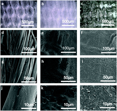
The white-coloured control cotton fabric is shown in Fig. 2(a). After the polyurethane treatment, the cotton fabric is dried in the oven at 60 °C for 10 min to remove any residual water, resulting in a layer film on the surface of the cotton fabric as Fig. 2(b). The GNP fabric (shown in Fig. 2(c)) is prepared by screen printing the GNP ink on a polyurethane (PU-)treated cotton fabric, thus forming a GNP ink layer (7.6 μm thick) on the surface. Fig. 2(d)–(l) shows the optical SEM images of the control cotton fabric (Fig. 2(d), (g) and (j)), the PU-treated cotton fabric (Fig. 2(e), (h) and (k)) and the GNP fabric (Fig. 2(f), (i) and (l)) at different magnifications. The SEM images (Fig. 2(d), (g) and (j)) show a typically fibrous structure with the fibres twisting with each other, thus producing a quite rough fabric surface. Comparing Fig. 2(e) and (d), the surface of the cotton fabric is evenly covered with a film and the texture of the fabric is faintly seen. The surface of the pre-treated cotton fibre is also covered with a layer of polyurethane film. The SEM image in Fig. 2(f) shows how the GNP ink uniformly conforms to the pre-treated cotton fabric. Compared with the control cotton fabric, the carbon content of the GNP fabric was increased (shown as Fig. S1, ESI†).Electrical and thermal characterization of the GNP fabric
The electrical and heating properties of the GNP fabric are characterized on a 2 × 2 cm sample, thus revealing a sheet resistance of Rs ∼ 169 Ω and conductivity of σ ∼ 778.6 S m−1, which is consistent with the conductivity values reported by previous works.35,38 The heating properties of the GNP fabric were investigated by monitoring the evolution of the temperature by an infrared camera (see methods) as a function of the applied voltage (VGNP) across the GNP fabric (between 2 V and 16 V; Fig. 3). The thermal images show a clear heating of the GNP fabric as a function of VGNP, increasing from T ∼ 19.6 °C to ∼72.5 °C.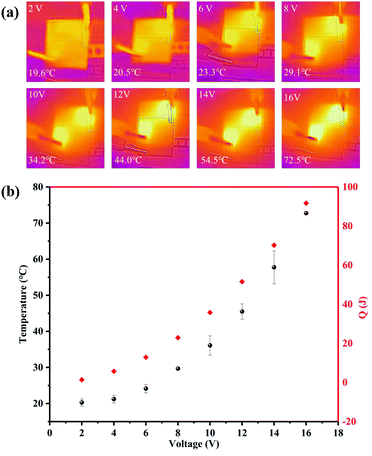 | ||
| Fig. 3 (a) Infrared thermal images of the conductive fabric at various VGNP; (b) plot of the temperature versus VGNP. | ||
The heating of our GNP fabric can be described by Joule's law, which defines the heat (Q) dissipated from a resistive material when voltage (or current) is applied as follows:39,40
| Q = V2/Rt |
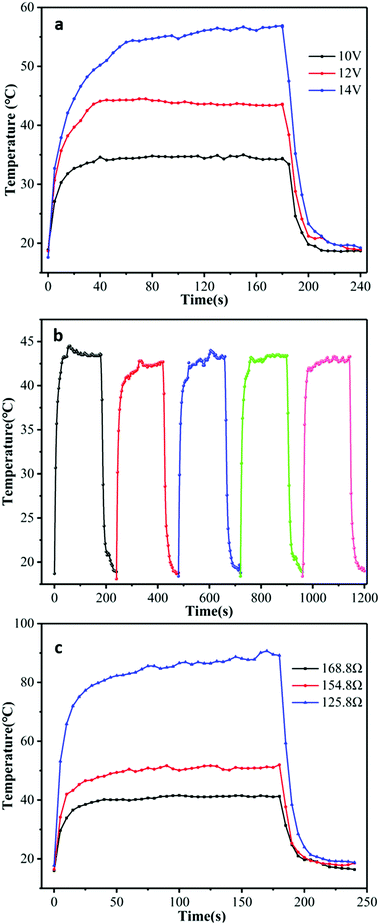
Fig. 4(a) shows the temperature profiles of the GNP fabric, as a function of t for VGNP = 10 V, 12 V and 14 V. All curves show a similar trend with a time response (τ, defined as the time required to reach the steady-state temperature, which was above 90% of the highest temperature from room temperature) of τ = 45 s, τ = 45 s and τ = 60 s for VGNP = 10 V, 12 V and 14 V, respectively. In this case, when VGNP = 10 V, only T ∼ 15 °C increase was observed, reaching T ∼ 35 °C after τ = 40 s. At VGNP = 14 V, the GNP fabric reached T ∼ 60 °C after τ = 60 s. The steady-state temperatures were reached for all samples in <60 s, thus demonstrating a faster response41,42 than graphene-based electro-thermal films, which reaches T ∼ 42 °C when 60 V is applied for 2 min.43 In all our GNP fabrics, the temperature remained stable on constant voltage applied and then returned to room temperature (T ∼ 20 °C) after about 60 s when power was turned off. This cooling rate can be explained by the nature of the cotton fabric that allows the heat to be very effectively dissipated by the material (the thermal conductivity of the cotton fabric is 0.026–0.065 W mK−1![[thin space (1/6-em)]](https://www.rsc.org/images/entities/char_2009.gif) 44).
44).
To investigate the stability of the GNP fabric, repeated heating and cooling cycles were carried out (as show in Fig. 4(b) and Fig. S3, ESI†). The temperature change of the GNP fabric was recorded over a period of 4 min (heating 3 min at VGNP = 12 V and cooling 1 min at VGNP = 0 V) for five cycles. As shown in Fig. 4(b), the heating/cooling curve remained almost unchanged after several cycles, thus reaching constantly T ∼ 42 °C at 12 V for 40 s after several heating and cooling cycles, thus indicating a good stability and repeatability. During each heating process, the temperature increased from room temperature (T ∼ 20 °C) to a steady value of T ∼ 43 °C in the initial 1 min, thus revealing a high heating rate of the GNP fabric. Moreover, in this case, the temperature of the GNP fabric gradually dropped to room temperature after 60 s because the voltage was set to VGNP = 0 V thanks to of the thermal conductivity of the cotton fabric. The time-dependent temperature profiles of the GNP fabrics with different Rs values are shown in Fig. 4(c). The temperature change of the GNP fabric was recorded with a period of 4 min (heating 3 min at VGNP = 12 V and cooling 1 min at VGNP = 0 V). The heat dissipated, Q, is influenced by the resistance of the GNP fabric. At the same voltage, the temperature of the GNP fabric is inversely proportional to Rs, thus confirming the heating by the Joule effect of the GNP fabric. For Rs ∼ 126 Ω, the temperature of the GNP fabric reaches T ∼ 90 °C, while it only reaches about 40 °C for Rs ∼ 169 Ω. The conductivity of our GNP fabric is higher than that reported for graphene anodes and cathodes (e.g., in microbial fuel cells).35
Electro-thermochromic cotton fabric performance
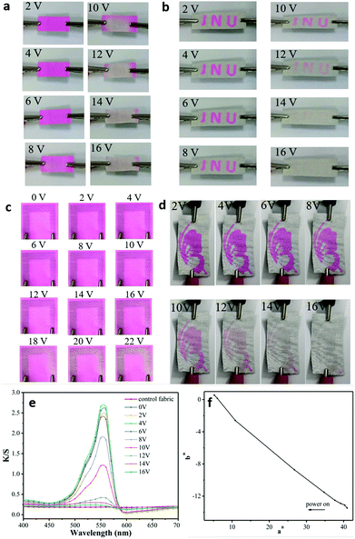
We developed a colour-changing smart fabric and a textile display by combining the colour changing property of the thermochromic polyurethane ink and the GNP fabric heater, as shown in Fig. 5. The rhodamine B ethylenediamine derivative thermochromic polyurethane ink was screen-printed on one side of the PU-treated cotton fabric, while the GNP ink was screen-printed on the other side (Fig. 5). The choice of depositing the two inks on the opposite sides aims to maximize the colour changing property of the thermochromic dye. The layer of polyurethane reduced the surface roughness38 of the fabric and prevented the absorption of the inks into the cotton fabric. The colour-changing property of the ET was investigated by monitoring colour parameters (i.e., K/S, where a* corresponds to the red and green colour combination and b* corresponds to yellow and blue colour combination) as a function of VGNP. The darker the red, the larger the a*. Fig. 6(a) shows how the colour of the thermochromic coating gradually disappears as the applied voltage increases.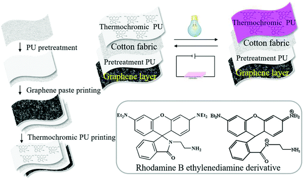 | ||
| Fig. 5 The schematic diagram of the procedure used to fabricate the ET. In the frame the molecular structure of the two rhodamine B derivatives. | ||
This is the result of the UV induction, which modifies the conjugate structure of the rhodamine B ethylenediamine derivative in the chemical composition of the polyurethane ink, thereby resulting in a change of the polyurethane optical properties.45 Our transparent thermochromic polyurethane starts reflecting in the region around magenta (λmax = 550 nm) after UV induction. It then returns colourless upon heating. The optical images of our ET at different voltages are shown in Fig. 6(a). Firstly, the thermochromic coating on the ET was activated by a treatment irradiation at λ = 254 nm for 3 min. This allows the lactam ring structure of the rhodamine B ethylenediamine derivative moiety in the thermochromic polyurethane to gradually change to an open-loop state with a quinolone structure.24 Then, we applied an increasing voltage from VGNP = 2 V to VGNP = 16 V. We can see the ET returning white as the applied voltage increased above VGNP = 10 V. This is because the Q generated by the GNP ink is sufficient to degrade the quinolone structure in the thermochromic ink, back-converting it into the colourless lactam ring when VGNP > 10–12 V. A VGNP = 12 V corresponds to a higher temperature than Tc, which consistently yields a transparent thermochromic coating. In the heating process, the GNP coating is the heat source, which transfers heat to the thermochromic polyurethane by radiation and conduction, as shown in the schematic of ET in Fig. 5.
An electro-thermochromic textile display
A series of ETDs are prepared by screen printing the GNP ink following the steps in Fig. 5 (Fig. 6(b)–(d)). The thermochromic polyurethane ink was screen-printed on the other side of the PU pre-treated cotton fabric with a series of predetermined patterns, “JNU” (Fig. 6(b)), a horseshoe (Fig. 6(c)) and a butterfly (Fig. 6(d)). The thermochromic pattern is then activated by UV induction at λ = 254 nm, thus giving rise to the patterns in magenta. A voltage VGNP > 12 V turns the patterns colourless, as shown in Fig. 6(b)–(d). Moreover, also in this case, we attribute the colour change of the printed pattern to the Joule heat generated by the GNP ink printed at the back of the fabric. Fig. 6(e), (f) and Table S1 (ESI†) show the colour parameters (colour difference, ΔE, the K/S value, a*, b*) of the ET as a function of λ for a VGNP range between 2 and 16 V. The K/S value shows peaks at 560 nm, which are in agreement with the standard peaks for the rhodamine B ethylenediamine derivative. In particular, the reference peak at λ = 560 nm decreased as the voltage increased and a* decreased, which confirms the colour change of the ET and the patterned ETD from magenta to white.Conclusion
We obtained electrochromic cotton fabrics and electrochromic textile-based displays using the thermal dissipation of a screen-printed, graphene-based ink to drive the colour switching of the thermochromic polyurethane ink coated on a fabric. The surface of a polyurethane fabric was covered by a graphene nanoplatelets ink uniformly. The graphene-based fabric-generated heat by the Joule effect upon voltage bias reached T ∼ 43 °C at 12 V. When further coated by thermochromic polyurethane and activated by UV induction, the composite fabric switched from magenta to white upon an applied voltage of 10 V, thus demonstrating suitable electro-thermochromic switching. The structure of the thermochromic polyurethane was changed to an open-loop state with a quinolone structure and returned to white when the applied voltage increased with the close-loop state of thermochromic polyurethane. This work paves the way for large-area, fast and stable thermochromic textile displays in future.Methods
Materials
The UV-induced thermochromic polyurethane ink was homemade24 (more details in S2, ESI†). Timrex KS25 graphite, sodium deoxycholate (SDC) and carboxymethyl cellulose sodium (CMC) were supplied by Aldrich Chemical Co Inc. The water-soluble thermal was purchased from Jining Baichuan Chemical Co., Ltd. The printing thickener was supplied by Transfar Co., Ltd.Formulation of the graphene-based ink
The GNP ink was prepared by dispersing graphite flakes (Timrex KS25) in deionized water (DIW) with sodium deoxycholate (SDC, 10 mg mL−1) followed by a microfluidic exfoliation (M110-P Microfluidizer; Microfluidics)6 for 70 cycles, thus obtaining a graphene-based dispersion. Sodium carboxymethyl cellulose (CMC; 7.5 g L−1) was blended with the graphene-based dispersion at 60 °C to obtain a GNP ink suitable for screen printing.Fabrication of the electro-thermochromic cotton fabric and display
The electro-thermochromic cotton fabric ET was prepared by screen printing on a polyurethane-coated cotton fabric, the graphene heater electrode on the back-side of the fabric, and the thermochromic UV-induced polyurethane on the front-side of the fabric by the following steps.Cotton fabric pre-treatment
The cotton fabric was pre-treated with water-soluble thermal curing polyurethane (65%), DIW (33%) and thickener (2%). Then, the cotton fabric was oven dried at 60 °C for 10 min and 100 °C for 5 min to prepare the pre-treated cotton fabric, denoted as PU pre-treated cotton fabric.Printing of GNP ink
The GNP ink is deposited via screen-printing on the polyurethane-treated cotton fabric, followed by a drying step at 60 °C for 10 min. The conductive fabric was denoted as the GNP fabric.Printing of thermochromic polyurethane
Screen-printing was performed with the UV induction thermochromic polyurethane on the back of the conductive fabric. Then, the electro-thermochromic fabric was dried at 60 °C for 10 min and baked at 130 °C for 5 min.Electron microscopy characterization
The original graphene ink was dried to prepare the sample for scanning electron microscopy. The surface morphology of the conductive fabric was investigated by SEM. A statistical analysis of over 150 flakes of the original GNP ink was used to estimate the statistics of the lateral size (defined as the longest side of the flake).Sheet resistance measurements
The sheet resistance of the conductive fabric was measured by a four-point probe system (KEITHLEY 2400 Source Meter Unit, US). The final resistance value of the fabric was measured with 10 different positions and averaged.Thickness measurements
The thickness of the GNP flakes was measured with a fabric thickness test equipment (YG141, Changzhou Second Textile Machinery Factory, China).Thermal and electro-thermochromic measurements
The average temperature of the fabric surface was monitored with an infrared camera (FLIR Ex). The infrared images of the conductive fabric were acquired at various VGNP applied across the GNP, with an exposure time of 2 min. The electro-thermochromic behaviour of the GNP fabric was investigated at various VGNP applied across the ET and ETDs.Colour parameters
The colour parameters (K/S value, L*, a*, b*, C°, h°) of the ETs and ETDs were acquired at various VGNP using Xrite-8400 spectrophotometer under a D65 illumination using a 10° standard observer.Conflicts of interest
There are no conflicts to declare.Acknowledgements
The authors acknowledge funding from the National First-Class Discipline Program of Light Industry Technology and Engineering (LITE2018-21), the 111 Project (B17021), the National Natural Science Foundation of China (No. 21975107), Fundamental Research Funds for the Central Universities (JUSRP51724B), the International Joint Research Laboratory for Advanced Functional Textile Materials, the China Scholarship Council (201706790076 and 201806790073), EPSRC grants EP/P02534X/2, EP/R511547/1, EP/T005106/1 and Trinity College, Cambridge. We wish to thank Dr Tian Carey and Mr Adrees Arbab for useful discussions.References
- J. Chen, Q. Peng, T. Thundat and H. Zeng, Chem. Mater., 2019, 31, 4553–4563 CrossRef CAS.
- Y. Guo, C. Dun, J. Xu, J. Mu, P. Li, L. Gu, C. Hou, C. A. Hewitt, Q. Zhang, Y. Li, D. L. Carroll and H. Wang, Small, 2017, 13, 1–9 Search PubMed.
- J. A. Rogers, T. Someya and Y. Huang, Science, 2010, 327, 1603–1607 CrossRef CAS.
- R. Cao, X. Pu, X. Du, W. Yang, J. Wang, H. Guo, S. Zhao, Z. Yuan, C. Zhang, C. Li and Z. L. Wang, ACS Nano, 2018, 12, 5190–5196 CrossRef CAS.
- D. Na, J. Choi, J. Lee, J. W. Jeon and B. H. Kim, ACS Appl. Mater. Interfaces, 2019, 11, 27353–27357 CrossRef CAS.
- P. G. Karagiannidis, S. A. Hodge, L. Lombardi, F. Tomarchio, N. Decorde, S. Milana, I. Goykhman, Y. Su, S. V. Mesite, D. N. Johnstone, R. K. Leary, P. A. Midgley, N. M. Pugno, F. Torrisi and A. C. Ferrari, ACS Nano, 2017, 11, 2742–2755 CrossRef CAS.
- S. Yao, J. Yang, F. R. Poblete, X. Hu and Y. Zhu, ACS Appl. Mater. Interfaces, 2019, 11, 31028–31037 CrossRef CAS.
- C. Lv, L. Hu, Y. Yang, H. Li, C. Huang and X. Liu, RSC Adv., 2015, 5, 25730–25737 RSC.
- Y. Lu, X. Xiao, Z. Cao, Y. Zhan, H. Cheng and G. Xu, Appl. Surf. Sci., 2017, 425, 233–240 CrossRef CAS.
- W. Zhang, X. Ji, C. Zeng, K. Chen, Y. Yin and C. Wang, J. Mater. Chem. C, 2017, 5, 8169–8178 RSC.
- A. C. Siegel, S. T. Phillips, B. J. Wiley and G. M. Whitesides, Lab Chip, 2009, 9, 2775–2781 RSC.
- Y. Li, Z. Zhang, X. Li, J. Zhang, H. Lou, X. Shi, X. Cheng and H. Peng, J. Mater. Chem. C, 2017, 5, 41–46 RSC.
- I. J. Kim, M. Ramalingam and Y. A. Son, Dyes Pigm., 2018, 151, 64–74 CrossRef CAS.
- M. Basson and T. S. Pottebaum, Exp. Fluids, 2012, 53, 803–814 CrossRef CAS.
- S. Hirata, K. S. Lee and T. Watanabe, Adv. Funct. Mater., 2008, 18, 2869–2879 CrossRef CAS.
- L. S. Ribeiro, T. Pinto, A. Monteiro, O. S. G. P. Soares, C. Pereira, C. Freire and M. F. R. Pereira, J. Mater. Sci., 2013, 48, 5085–5092 CrossRef CAS.
- C. Yu, Y. Zhang, D. Cheng, X. Li, Y. Huang and J. A. Rogers, Small, 2014, 10, 1266–1271 CrossRef CAS.
- A. Raditoiu, V. Raditoiu, C. A. Nicolae, M. F. Raduly, V. Amariutei and L. E. Wagner, Dyes Pigm., 2016, 134, 69–76 CrossRef CAS.
- S. Ayazi-Yazdi, L. Karimi, M. Mirjalili and M. Karimnejad, J. Text. Inst., 2017, 108, 856–863 CrossRef CAS.
- X. Geng, W. Li, Y. Wang, J. Lu, J. Wang, N. Wang, J. Li and X. Zhang, Appl. Energy, 2018, 217, 281–294 CrossRef CAS.
- F. Azizian, A. J. Field and B. M. Heron, Dyes Pigm., 2013, 99, 431–439 CrossRef.
- K. Ogasawara, K. Nakamura and N. Kobayashi, J. Mater. Chem. C, 2016, 4, 4805–4813 RSC.
- X. Hu, X. Zhang, J. Liu and J. Dai, Polym. Int., 2014, 63, 453–458 CrossRef CAS.
- X. Ji, W. Zhang, F. Ge, C. Wang, Y. Yin and K. Chen, Prog. Org. Coat., 2019, 131, 111–118 CrossRef CAS.
- A. Bhattacharyya and M. Joshi, Fibers Polym., 2011, 12, 734–740 CrossRef CAS.
- K. R. Karpagam, K. S. Saranya, J. Gopinathan and A. Bhattacharyya, J. Text. Inst., 2017, 108, 1122–1127 CAS.
- C. Wei, L. Fan, W. Rao, Z. Bai, W. Xu, H. Bao and J. Xu, Cellulose, 2017, 24, 5187–5196 CrossRef CAS.
- A. Laforgue, J. Mater. Chem., 2010, 20, 8233–8235 RSC.
- B. Zhou, Y. Li, G. Zheng, K. Dai, C. Liu, Y. Ma, J. Zhang, N. Wang, C. Shen and Z. Guo, J. Mater. Chem. C, 2018, 6, 8360–8371 RSC.
- B. Zhou, M. Su, D. Yang, G. Han, Y. Feng, B. Wang, J. Ma, J. Ma, C. Liu and C. Shen, ACS Appl. Mater. Interfaces, 2020, 12, 40859–40869 CrossRef.
- B. Zhou, X. Han, L. Li, Y. Feng, T. Fang, G. Zheng, B. Wang, K. Dai, C. Liu and C. Shen, Compos. Sci. Technol., 2019, 183, 107796 CrossRef CAS.
- A. Laforgue, S. Dubost, M. F. Champagne and L. Robitaille, ACS Appl. Mater. Interfaces, 2012, 4, 3136–3168 CrossRef.
- H. Sun, D. Chen, C. Ye, X. Li, D. Dai, Q. Yuan, K. W. A. Chee, P. Zhao, N. Jiang and C. Te Lin, Appl. Surf. Sci., 2018, 435, 809–814 CrossRef CAS.
- F. Torrisi, D. Popa, S. Milana, Z. Jiang, T. Hasan, E. Lidorikis and A. C. Ferrari, Adv. Opt. Mater., 2016, 4, 1088–1097 CrossRef CAS.
- T. P. Call, T. Carey, P. Bombelli, D. J. Lea-Smith, P. Hooper, C. J. Howe and F. Torrisi, J. Mater. Chem. A, 2017, 5, 23872–23886 RSC.
- J. Ren, C. Wang, X. Zhang, T. Carey, K. Chen, Y. Yin and F. Torrisi, Carbon N. Y., 2017, 111, 622–630 CrossRef CAS.
- S. Qiang, T. Carey, A. Arbab, W. Song, C. Wang and F. Torrisi, Nanoscale, 2019, 11, 9912–9919 RSC.
- T. Carey, S. Cacovich, G. Divitini, J. Ren, A. Mansouri, J. M. Kim, C. Wang, C. Ducati, R. Sordan and F. Torrisi, Nat. Commun., 2017, 8, 1–11 CrossRef CAS.
- C. Celle, C. Mayousse, E. Moreau, H. Basti, A. Carella and J. P. Simonato, Nano Res., 2012, 5, 427–433 CrossRef CAS.
- W. Lan, Y. Chen, Z. Yang, W. Han, J. Zhou, Y. Zhang, J. Wang, G. Tang, Y. Wei, W. Dou, Q. Su and E. Xie, ACS Appl. Mater. Interfaces, 2017, 9, 6644–6651 CrossRef CAS.
- Y. Yu, W. Shen, F. Li, X. Fang, H. Duan, F. Xu, Y. Xiong, W. Xu and W. Song, RSC Adv., 2017, 7, 28670–28676 RSC.
- G. Huang, L. Liu, R. Wang, J. Zhang, X. Sun and H. Peng, J. Mater. Chem. C, 2016, 4, 7589–7594 RSC.
- D. Sui, Y. Huang, L. Huang, J. Liang, Y. Ma and Y. Chen, Small, 2011, 7, 3186–3192 CrossRef CAS.
- A. Abbas, Y. Zhao, J. Zhou, X. Wang and T. Lin, Fibers Polym., 2013, 14, 1641–1649 CrossRef CAS.
- Z. Wang, Z. Ma, Y. Wang, Z. Xu, Y. Luo, Y. Wei and X. Jia, Adv. Mater., 2015, 27, 6469–6474 CrossRef CAS.
Footnote |
| † Electronic supplementary information (ESI) available. See DOI: 10.1039/d0tc03144e |
| This journal is © The Royal Society of Chemistry 2020 |

