
 Open Access Article
 This Open Access Article is licensed under a
 Creative Commons Attribution 3.0 Unported Licence
High performance conjugated terpolymers as electron donors in nonfullerene organic solar cells†
Sri Harish Kumar
Paleti
 a,
Nicola
Gasparini
a,
Christos L.
Chochos
*bc and
Derya
Baran
*a
a,
Nicola
Gasparini
a,
Christos L.
Chochos
*bc and
Derya
Baran
*a
aKing Abdullah University of Science and Technology (KAUST), Physical Science and Engineering Division, KAUST Solar Center (KSC), Thuwal 23955-6900, Saudi Arabia. E-mail: derya.baran@kaust.edu.sa
bAdvent Technologies SA, Stadiou Street, Platani, Rio, Patras 26504, Greece
cInstitute of Chemical Biology, National Hellenic Research Foundation, 48 Vassileos Constantinou Avenue, Athens, 11635, Greece. E-mail: chochos@eie.gr
First published on 18th September 2020
Abstract
We demonstrate the synthesis of three π-conjugated terpolymers based on the nonconventional molecular design strategy D1–D2–D1–A comprising two different multi-fused ladder-type arene electron donating moieties [(4,4′-bis(2-ethylhexyl)dithieno[3,2-b:2′,3′-d]silole)-2,6-diyl (DTS) as D1 and thienyl-substituted benzo[1,2-b:4,5-b′]dithiophene (BDT) derivatives as D2] and an electron withdrawing unit [5,6-difluoro-2,1,3-benzothiadiazole (DFBT) as A]. The implementation of these materials as electron donors is explored in high performance near infrared non-fullerene acceptor (NFA) organic solar cells utilizing the benchmark low bandgap NFA IEICO-4F. The triple bulk heterojunction blend systems provide the basis for a detailed structure–property–performance relationship in terms of BDT's thienyl substitution (alkyl, alkylthio and fluoro) by investigating the correlations between the molecular energy level alignments, performance, and device physics of OSCs. The alkylthienyl-BDT based π-conjugated terpolymer [P(DTS-BDT-DFBT)] exhibits the best photovoltaic performance delivering a power conversion efficiency of 10% with a high short circuit current density of 22.7 mA cm−2. The combination of optoelectronic measurements and morphological analyses revealed the suppression of field dependent charge recombination in P(DTS-BDT-DFBT):IEICO-4F as compared to alkylthiothienyl-BDT [P(DTS-BDTS-DFBT):IEICO-4F] and fluoro-substituted thienyl-BDT [P(DTS-BDTF-DFBT):IEICO-4F] based OSC devices.
Introduction
Bulk-heterojunction (BHJ) organic solar cells (OSCs) based on the blends of donor polymers (or small molecules) and non-fullerene derivatives as acceptors have attracted attention due to their unique advantages such as solution processability, flexibility, light weight, and ability to be coated over a large area at low manufacturing costs.1–3 Recent breakthroughs in the field of OSCs have increased the power conversion efficiencies (PCEs) reaching 18% in single junction OSCs.4–10 The development of non-fullerene acceptors (NFAs) and the chemical optimization of π-conjugated donor polymers are attributed to these high efficiencies.11–18 Regarding the latter, a small bandgap of π-conjugated donor polymers is usually achieved by using the “donor–acceptor” (D–A) strategy for designing the polymer backbone. A proper alignment of the highest occupied molecular orbital (EHOMO) and lowest unoccupied molecular orbital (ELUMO) energy levels can be achieved by tuning the relative strength of the electron-donating unit (D) and the electron-deficient unit (A) directly or through a π-conjugated linkage (π). In particular, D–A polymers containing at least one multi-fused ladder-type arene segment are favoured for use as an active material in organic solar cells. Favourable charge transport properties can be attained by using building blocks with large π-conjugation and good planarity, enhancing molecular weights, fine-tuning the solubilizing side chains, etc.19–24For better fine-tuning of the EHOMO and ELUMO levels, and, as a consequence, the bandgap of the donor materials, a nonconventional molecular design strategy, beyond the classical D–A approach, for new π-conjugated polymers with high photovoltaic performance is being explored in the field; however, very limited studies have been presented up to now.25–32 Taking this into account, a facile D1–D2–D1–A π-conjugated polymer backbone is presented in this work by the addition of another multi-fused ladder-type arene as a building block between the D and A moieties in a regular alternation and not in a random approach. The beneficial role of the more extended structures, especially those containing more than one electron donating unit connected to each other, hence increasing the D–A distance, has been highlighted.33–35 In addition, it is of utmost importance to gain an in-depth understanding of the role of each monomer in these extended chemical structures in (i) the optoelectronic properties and (ii) the corresponding device performance. In order to fully resolve these open questions, this contribution utilizes the successful synthesis of a series of new D1–D2–D1–A π-conjugated terpolymers (Scheme 1), by keeping fixed the A unit (5,6-difluoro-2,1,3-benzothiadiazole, DFBT) and utilizing the (4,4′-bis(2-ethylhexyl)dithieno[3,2-b:2′,3′-d]silole)-2,6-diyl (DTS) as the D1 multi-fused arene and various 2D-benzo[1,2-b:4,5-b′]dithiophene (BDT) multi-fused derivatives as the D2 building blocks containing alkylthienyl-, alkylthiothienyl- or fluoro-substituted thienyl side groups. Besides the other advantages, the presence of this “ternary”-type chemical structure in the polymer backbone enables solubility in common organic solvents due to the presence of short branch alkyl side chains on the DTS and BDT units versus the insoluble corresponding “binary”-type D–A polymers of DTS-DFBT and BDT-DFBT, respectively.36 Furthermore, this series of π-conjugated polymers allowed us to perform structure–property relationship studies by investigating the significant effect caused by a relatively small change in the chemical structure of the 2D-BDT central unit on the optoelectronic properties as well as the device performance. According to these findings, we demonstrate that the devices based on the new donor design architecture present a promising PCE of 10%.
 | ||
| Scheme 1 Synthetic route to D1–D2–D1–A π-conjugated polymers in this study. | ||
Results and discussion
Monomer and polymer synthesis
DTS, 2D-BDTs and DFBT moieties were incorporated using a D1–D2–D1–A approach to construct a polymer backbone. DTS moieties have attracted much interest due to their efficient charge transport through the tight interchain packing of conjugated polymers.37 Silole-containing organic materials have shown higher charge transport38 and better solar cell properties39 compared to their carbon analogues,40 which are mainly due to the longer Si–C bond length (1.89 Å) than the C–C bond length (1.53 Å) in the cyclopentadiene unit, allowing efficient interchain packing and strong π–π interactions.37 With these favourable features in mind, DTS and DFBT were combined to synthesize 4,7-bis(6-bromo-4,4-bis(2-ethylhexyl)-4H-silolo[3,2-b:4,5-b′]dithiophen-2-yl)-5,6-difluorobenzo[c][1,2,5]thiadiazole (M1) (Scheme 1) which is expected to enforce the high coplanarity of the resulting polymer backbone and tight π–π stacking due to the presence of two fused polycyclic DTS units around DFBT and the strong non-covalent interactions (H⋯F, S⋯F, S⋯N,)41–43 among the different building blocks within the polymer chains. Furthermore, the 2D-BDT unit has become one of the most successful building blocks in the synthesis of highly efficient photovoltaic materials.44 The rigid and planar conjugated structure of BDT makes it attractive for achieving highly tuneable molecular energy levels and optical band gaps through side group functionalization as well as high hole mobilities. Therefore, as a next step M1 is combined with either (4,8-bis(5-(2-ethylhexyl)thiophen-2-yl)benzo[1,2-b:4,5-b′]dithiophene-2,6-diyl)bis(trimethylstannane) (M2), (4,8-bis(5-((2-ethylhexyl)thio)thiophen-2-yl)benzo[1,2-b:4,5-b′]dithiophene-2,6-diyl)bis(trimethylstannane) (M3), or (4,8-bis(5-(2-ethylhexyl)-4-fluorothiophen-2-yl)benzo[1,2-b:4,5-b′]dithiophene-2,6-diyl)bis(trimethylstann-ane) (M4) to provide P(DTS-BDT-DFBT), P(DTS-BDTS-DFBT) and P(DTS-BDTF-DFBT), respectively (Scheme 1). Stille aromatic cross-coupling polymerization conditions45 were used for the synthesis of the polymers using as the catalyst 0.03 equivalents of tris(dibenzylideneacetone)dipalladium(0) [Pd2(dba3)] and 0.12 equivalents of tri(o-tolyl)phosphine [P(o-tol)3] in a solution of toluene. After purification, using Soxhlet extraction, all the terpolymers were extracted from the chloroform (CF) batch. The average molecular weight per number ( ), the average molecular weight per weight (
 ) and the dispersity (Đ) of the polymers estimated by gel permeation chromatography (GPC) based on polystyrene standards of narrow dispersity at 25 °C and using chloroform as the solvent are presented in Fig. S1 and Table S1 (ESI†).
Optoelectronic properties
The thin film absorption spectra of all three polymer films were recorded and normalized by their respective film thicknesses, as shown in Fig. 1a. All polymers show two distinct absorption bands in the wavelength ranges of 400–520 nm and 560–750 nm corresponding to intramolecular charge transfer (ICT) and π–π* transition, respectively.44 While the absorption maximum (λmax = 670 nm) does not alter the replacement of the ethylhexyl side chain with the ethylhexylthio side chain and the addition of fluorine atoms on the D2 moiety, the absorption co-efficient decreases and there is a slight shift in the onset of the absorption spectrum. The red shift of the energy onset for P(DTS-BDTS-DFBT) can be partly attributed to the structural change of the alkyl side chain from ethylhexyl to ethylhexylthio.46,47 The EHOMO levels were measured using photoelectron spectroscopy in air (PESA) and then the ELUMO levels were calculated using the optical bandgap from the absorption spectra (Fig. S2, ESI† and Fig. 1b). The results suggest that the chemical substitution on the D2 moiety affects significantly the EHOMO levels. In more detail, the EHOMO level of P(DTS-BDT-DFBT) is more upshifted versus vacuum due to the σ-inductive effect of the alkyl substituents as compared to the mesogenic effect of the alkylthio and fluoro atoms on P(DTS-BDTS-DFBT) and P(DTS-BDTF-DFBT), respectively. Between P(DTS-BDTS-DFBT) and P(DTS-BDTF-DFBT) the mesogenic effect of alkylthio at the 2-position of the thienyl groups in P(DTS-BDTS-DFBT) is stronger than that of the fluorine atoms at the 3-position of the thienyl side groups in P(DTS-BDTF-DFBT), which leads to a reduced (downshifted versus vacuum) EHOMO level of P(DTS-BDTS-DFBT) by 0.1 eV as compared to P(DTS-BDTF-DFBT). The experimentally determined EHOMO levels show the same trend as the theoretically calculated DFT values (Fig. S3, ESI†) but with a slight difference in the absolute values. During DFT simulations, all side chains are assumed as methyl groups. This might be one of the reasons for the difference in the experimentally determined and theoretically calculated values. | ||
| Fig. 1 Photovoltaic performance of devices: (a) absorption spectra of the pristine P(DTS-BDT-DFBT), P(DTS-BDTS-DFBT) and P(DTS-BDTF-DFBT) films; (b) energy level diagram of the donor and acceptor materials obtained using photoelectron spectroscopy in air, where the optical bandgaps are 1.63 eV (P(DTS-BDT-DFBT)), 1.63 eV (P(DTS-BDTS-DFBT)) and 1.64 eV (P(DTS-BDTF-DFBT)); (c) current density–voltage characteristics of P(DTS-BDT-DFBT), P(DTS-BDTS-DFBT) and P(DTS-BDTF-DFBT) based solar cells under solar simulator illumination (100 mW cm−2); (d) external quantum efficiency curves of the devices shown in (c). | ||
Photovoltaic properties
The solar cell performance was examined by blending the respective polymers with the NFA, IEICO-4F. All OSCs were fabricated with inverted device architecture based on ITO/ZnO (solgel)/terpolymers:IEICO-4F/MoOx/Ag, where the active layer was spin-coated in a nitrogen-controlled atmosphere. We found that the best device performances of P(DTS-BDTS-DFBT) and P(DTS-BDTF-DFBT) are achieved without any post treatment (thermal treatment or solvent additive), while for P(DTS-BDT-DFBT) devices 1% (V/V%) chloronaphthalene (CN) was used as the solvent additive in chlorobenzene. A systematic optimization was carried out for an optimum donor-to-acceptor ratio under post-processing annealing conditions to achieve the best device performance, details of which can be found in Table S2 (ESI†).Fig. 1c shows the J–V curves of the optimized solar cells under simulated AM 1.5G solar irradiation. P(DTS-BDT-DFBT) based devices achieved a short circuit current density (Jsc) of 22.7 mA cm−2, an open circuit voltage (Voc) of 0.71 V, a fill factor (FF) of 63% and a PCE of 10.0%. The average efficiency over 18 devices is approximately 9.5% (Fig. S4, ESI†). Under the same fabrication conditions, P(DTS-BDTS-DFBT) and P(DTS-BDTF-DFBT) based OSCs achieved the maximum PCEs of 7.0% and 5.8%, respectively. In the following part, we investigate the lower Jsc and FF values of P(DTS-BDTS-DFBT) and P(DTS-BDTF-DFBT). The values of all three devices are shown in Table 1 for comparison. The external quantum efficiency (EQE) spectra of the devices were also recorded (Fig. 1d). The EQE spectrum of the P(DTS-BDT-DFBT):IEICO-4F device demonstrates a significantly higher photoresponse in the whole range of the spectrum as compared to the alkylthio- or fluoro-substituted terpolymer based OSC devices, resulting in higher Jsc. It is widely known that Jsc is primarily determined by the generation and dissociation of the excitons at the donor/acceptor (D/A) interfaces and the transport of the charge carriers to the electrodes. This means that either the charges are not being generated or the generated charges are being recombined before reaching their respective electrodes.
| Active layer | J sc, mA cm−2 | V oc, V | FF, % | PCE, % |
|---|---|---|---|---|
| P(DTS-BDT-DFBT):IEICO-4F | 22.7 (21.9 ± 0.8) | 0.71 (0.71 ± 0.01) | 62.5 (62.4 ± 0.1) | 10.0 (9.7 ± 0.3) |
| P(DTS-BDTS-DFBT):IEICO-4F | 16.4 (15.6 ± 0.8) | 0.80 (0.79 ± 0.06) | 54.7 (53.9 ± 0.8) | 7.0 (6.3 ± 0.7) |
| P(DTS-BDTF-DFBT):IEICO-4F | 12.9 (12.6 ± 0.7) | 0.81 (0.80 ± 0.07) | 55.2 (55.2 ± 0.01) | 5.8 (5.3 ± 0.4) |
Before studying the recombination dynamics, the efficiency of the exciton splitting at the D/A interface was studied using photoluminescence spectroscopy (PL). This gives an insight into the extent of D/A phase mixing and exciton dissociation in the BHJ blend film. Fig. 2a indicates that the excited state of the donor terpolymers is quenched to a similar extent in all blend films, which infers the good mixing of donor and acceptor phases. To shed light on the recombination processes of the devices, we measured photocurrent density (Jph) as a function of effective voltage (Veff), as shown in Fig. 2b. The measured photocurrent is defined as Jph= JL–Jd, where JL and Jd are the current densities under illumination at 100 mW cm−2 and in the dark, respectively. Veff is given by Veff = Vo–V, where Vo is the voltage at which the photogenerated charge carriers are zero and V is the applied voltage.48 The J–V plots indicate that Jph quickly saturates for the P(DTS-BDT-DFBT) based OSCs as it tends towards higher effective voltages. On the other hand, for the P(DTS-BDTS-DFBT) and P(DTS-BDTF-DFBT) based OSCs the charges were not saturated even at high effective voltages. This infers that the generated electron–hole pairs recombine before being collected at the electrodes.49 In addition, in the case of the P(DTS-BDTF-DFBT) based OSCs, the generated charges at lower effective voltages are lower in comparison to the other two polymer-based devices. The observed trend with the higher Jsc value as well as the higher absorption coefficient of P(DTS-BDT-DFBT) indicates that exciton generation and separation is limited by functionalization with sulphur and fluoro substituents in P(DTS-BDTS-DFBT) and P(DTS-BDTF-DFBT), respectively. A similar trend was observed by performing EQE measurements in reverse bias (Fig. S5, ESI†).
 | ||
| Fig. 2 (a) Photoluminescence of the pristine and blend films; (b) photocurrent density of P(DTS-BDT-DFBT):IEICO-4F, P(DTS-BDTS-DFBT):IEICO-4F and P(DTS-BDTF-DFBT):IEICO-4F based solar cells as a function of effective voltage under 1 sun illumination; (c) charge carrier mobility and lifetime of three different solar cells; (d) charge carrier mobility–lifetime product of three different solar cells. For (c) and (d) 1: P(DTS-BDT-DFBT):IEICO-4F; 2: P(DTS-BDTS-DFBT):IEICO-4F; and 3: P(DTS-BDTF-DFBT):IEICO-4F. | ||
Next, we focus on the difference in the FF values of P(DTS-BDT-DFBT), P(DTS-BDTS-DFBT) and P(DTS-BDTF-DFBT) based devices. First, we calculated the hole mobility (μh) in these novel donor polymers as pristine thin films and as blend films by using the space charge limited current (SCLC) technique (Fig. S6, ESI†). The μh values of the pristine polymers are as follows: 4.35 × 10⁻⁵ cm2 V−1 s−1 (P(DTS-BDT-DFBT)), 3.69 × 10⁻⁵ cm2 V−1 s−1 (P(DTS-BDTS-DFBT)), and 1.57 × 10⁻⁵ cm2 V−1 s−1 (P(DTS-BDTF-DFBT)). In the blend film, the μh values are as follows: 4.52 × 10⁻⁴ cm2 V−1 s−1 (P(DTS-BDT-DFBT)), 2.91 × 10⁻⁵ cm2 V−1 s−1 (P(DTS-BDTS-DFBT)), and 7.40 × 10⁻⁵ cm2 V−1 s−1 (P(DTS-BDT-DFBT)). Later the charge carrier mobilities μ of the respective donor material based devices were determined by using the photoinduced charge carrier extraction using a linearly increasing voltage (photo-CELIV)50 technique. This technique gives the rare advantage of measuring the mobility of photogenerated charge carriers without using single carrier type devices.51,52 Fig. S7 (ESI†) shows the photo-CELIV transients of the three systems, which were recorded by applying a 2 V/60 μs linearly increasing reverse bias pulse and a delay time (td) of 1 μs. From the measured photocurrent transients, the charge carrier mobility (μ) is calculated using the following equation (1):
 | (1) |
We then analysed the charge carrier recombination lifetime (τ) in the three systems using the transient photovoltage (TPV) technique.53 Solar cells were held under white light bias, which was used to control Voc. A small optical perturbation was applied using a green laser as the excitation source with a wavelength of 532 nm, which resulted in a voltage transient with an amplitude ΔV ≪ Voc. The intensity of the laser pulse was attenuated as necessary to keep ΔV less than 10 mV. As the cell is maintained in the Voc condition, the generated charge carriers are forced to remain in the cell and eventually recombine.54,55 These decay kinetics are used to monitor charge recombination kinetics.
Fig. S8 (ESI†) shows the decay kinetics of the three devices under open circuit conditions. The kinetics clearly shows that charges recombine quicker in P(DTS-BDTS-DFBT) and P(DTS-BDTF-DFBT) devices, compared to P(DTS-BDT-DFBT) devices, which is reflected in the calculated charge carrier lifetime with the lifetimes of 2.63 μs (P(DTS-BDT-DFBT)), 1.65 μs (P(DTS-BDTS-DFBT)) and 1.14 μs (P(DTS-BDTF-DFBT)) (Fig. 2c). Thus, P(DTS-BDT-DFBT) devices show not only a higher lifetime, but also a higher mobility of charge carriers. This suggests that introducing the alkylthio or fluoro atoms as substituents at 2D-BDT favours the bimolecular recombination of charges in (P(DTS-BDTF-DFBT)) and (P(DTS-BDTS-DFBT)) based solar cells.
Knowledge of charge carrier mobility and charge carrier lifetime allows the calculation of the μτ product. The calculated μτ values of 6.2 × 10⁻¹⁰ cm2 V−1 (P(DTS-BDT-DFBT)), 1.7 × 10⁻¹⁰ cm2 V−1 (P(DTS-BDTF-DFBT)), and 2.1 × 10⁻¹⁰ cm2 V−1 (P(DTS-BDTS-DFBT)) agree with the fill factor values of the devices. Thus, the charge carrier efficiency indicates that the (P(DTS-BDT-DFBT)) based devices exhibit enhanced efficiency in comparison to the sidechain modification counterparts (Fig. 2d).
Generally, the BHJ blend morphology has a substantial impact on charge transport and photocurrent generation. Hence, further morphological investigations were carried out. We started our analysis by investigating the surface topography of the photo-active layer through intermittent contact mode atomic force microscopy (AFM, Fig. 3(a–c)). Interestingly, the topographic features look similar, suggesting that the donor and acceptor phases are mixed well in all three systems. Also, similar root mean square (RMS) values suggest similar roughness of the films. While we cannot associate these domains with a particular component of the BHJ, the topographic images do not reveal obvious differences between the three systems studied. Furthermore, we performed transmission electron microscopy (TEM) investigations of the active layer films. Fig. 3(d–f) show the TEM bright field images of all three blend films. In the case of P(DTS-BDTF-DFBT):IEICO-4F the formation of separate domains is clearly present. The other two blend films show a finer intermixing of the polymer and the IEICO-4F phase. This finer intermixing in the morphology is reflected in the modest charge generation and transport of the P(DTS-BDTF-DFBT) based devices.
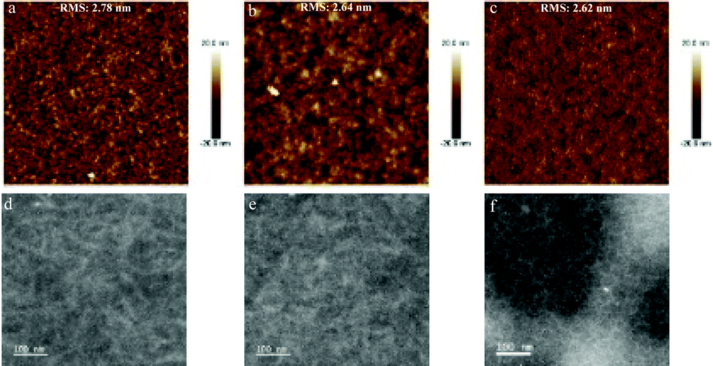 | ||
| Fig. 3 (a–c) AFM images of P(DTS-BDT-DFBT), P(DTS-BDTS-DFBT) and P(DTS-BDTF-DFBT) based solar cells. All three AFM images show similar roughness. (d–f) TEM bright field images of P(DTS-BDT-DFBT), P(DTS-BDTS-DFBT), and P(DTS-BDTF-DFBT) based solar cells. | ||
Conclusion
In conclusion, we synthesized a series of novel and well-defined terpolymers (D1–D2–D1–A) and explored their photovoltaic behaviour when blended with a nonfullerene acceptor (IEICO-4F). We obtained a high PCE of more than 10.0% for P(DTS-BDT-DFBT):IEICO-4F solar cells, whereas P(DTS-BDTS-DFBT):IEICO-4F and P(DTS-BDTF-DFBT):IEICO-4F devices delivered lower PCEs of 7.0% and 5.8%, respectively. The combination of optoelectronic characterizations revealed that the devices based on (P(DTS-BDTS-DFBT):IEICO-4F) and (P(DTS-BDTF-DFBT):IEICO-4F) exhibit field-dependent charge generation and μτ-limited charge carrier extraction, which lead to lower FF values. Overall, the synthesis of D1–D2–D1–A donor polymers based on the DTS, BDT and DFBT moieties represents a new strategy for designing donor materials in organic solar cells. Chemical substitution by fluoro and sulphur atoms on the 2D-BDT central moiety (D2) that tend to provide electrons in the polymer backbone by mesogenic effects has been shown to be detrimental to the photovoltaic performance which results in increased charge recombination for this type of chemical motif (D1–D2–D1–A). Our work provides a structure–property relation via chemical substitution in the unexplored types of D1–D2–D1–A π-conjugated terpolymers which contribute to shaping the rational design of high-performance semiconducting terpolymers.Experimental section
Materials
All reactions were considered as air and light sensitive and were performed under an argon atmosphere and in the dark. All glassware was washed using a surfactant, rinsed with excess water, acetone and methylene chloride, and dried in an oven at 120 °C. All solvents and reagents were commercially purchased from Aldrich. Toluene was distilled using calcium hydride (CaH2) prior to polymerization. 1H and 13C NMR spectra were recorded on a Bruker Avance 600 spectrometer (at 600 and 100 MHz, respectively).Synthesis
The syntheses of M1, M2, M3 and M4 were performed according to the previously reported methods. The general experimental conditions for the polymerization are analytically described as follows: Dibromo M1 (0.15 mmol) and distannyl substituted BDT (M2–M4) derivatives (0.15 mmol) were dissolved in dry toluene (0.025 M). Then, tris(dibenzylideneacetone)dipalladium(0) [Pd2(dba)3] (0.03 equiv.) and tri(o-tolyl)phosphine (P(o-tol)3) (0.12 equiv.) were added and the reaction mixture was stirred at 120 °C under an argon atmosphere for 48 h. The polymers were purified by precipitation in methanol, filtered and washed using Soxhlet apparatus with methanol, acetone, hexane and chloroform. The chloroform fractions were evaporated under reduced pressure and the polymers were precipitated in methanol, filtered through a 0.45 mm PTFE filter and finally dried under high vacuum, yielding a dark blue solid with metallic appearance. The yields are as follows: P(DTS-BDT-DFBT) = 91%, P(DTS-BDTS-DFBT) = 88% and P(DTS-BDTF-DFBT) = 72%.Gel permeation chromatography (GPC)
The average molecular weights per number ( ) and per weight (
 ) and the dispersity (Đ) were determined with GPC at room temperature on a GPC system using a PL-GEL 10 μm guard column, two PLGel 10 μm MIXED-B columns and chloroform as the eluent. The instrument was calibrated with narrow polystyrene standards with Mp ranging from 4830 g mol−1 to 3
![[thin space (1/6-em)]](https://www.rsc.org/images/entities/char_2009.gif) 242000 g mol−1.
242000 g mol−1.
Device fabrication
IEICO-4F was purchased from 1-Materials Inc. A zinc oxide sol–gel solution was prepared by dissolving the zinc acetate dihydrate (Zn(CH3COO)2·2H2O, 99%, Sigma) precursor in ethanolamine (NH2CH2CH2OH, 98%, Sigma) and 2-methoxyethanol (CH3OCH2CH2OH, 98%, Sigma). The solution was stirred overnight at room temperature. Pre-patterned indium tin oxide (ITO) glass substrates were cleaned in an ultrasonic bath using acetone (8 minutes) and isopropyl alcohol (8 minutes) successively. Later the substrates were dried using nitrogen and treated with oxygen plasma. The ZnO sol gel was spin-coated at 4000 rpm for 40 s. The films were annealed at 200 °C for 10 minutes in air. The polymer:IEICO-4F blend solutions were then spin-coated at 1000 rpm inside a glove box. The processed active layers, P(DTS-BDT-DFBT):IEICO-4F (1:1, wt%, 20 mg ml−1), P(DTS-BDTS-DFBT):IEICO-4F (1:1, wt%, 20 mg ml−1) and P(DTS-BDTF-DFBT):IEICO-4F (1:2, wt%, 20 mg ml−1), were prepared by dissolving the polymer and small molecule acceptor in chlorobenzene overnight with stirring at 80 °C. The processing additive of 1% chloronaphthalene was added to the P(DTS-BDT-DFBT):IEICO-4F blend solution. Finally, the devices were fabricated by the thermal evaporation of MoOx (10 nm) and silver (100 nm) at ∼1 × 10⁻⁶ bar. The active area of each cell is 0.1 cm2.
Electrical characterization
I–V curves and light intensity measurements were carried out using a Keithley 2400 source meter and a WAVELABS SINUS-70 solar simulator calibrated to 1 sun, AM 1.5G. The EQEs of devices were measured using an integrated system from Enlitech, Taiwan.Photo-CELIV
The devices were illuminated with a 405 nm laser diode. Current transients were recorded across an internal 50 Ω resistor of an oscilloscope. After a variable delay time, a linear extraction ramp was applied via a function generator. The ramp, which was 20 μs long and 2 V in amplitude, was set to start with an offset matching the Voc of the cell for each delay time.TPV
A 405nm laser diode was used to keep the solar cells in approximately Voc conditions. Driving the laser intensity with a waveform generator (Agilent 33500B) and measuring the light intensity with a highly linear photodiode allowed reproducible adjustments of the light intensity with an error below 0.5% over a range from 0.2 to 1 sun. A small perturbation was induced with a second 532nm laser diode driven by a function generator from Agilent. The intensity of the short (50ns) laser pulse was adjusted to keep the voltage perturbation below 10mV. After the pulse, the voltage decays back to its steady state value in a single exponential decay. The characteristic decay time was determined from a linear fit to a logarithmic plot of the voltage transient, and returned the small perturbation charge carrier lifetime.
Optical and morphological characterization
The absorption spectra of pristine films were measured using a Cary 5000 UV-vis-NIR spectrophotometer (Agilent Technologies).An Agilent 5400 AFM in the tapping mode was used to measure the surface morphology of blend films.
Electron and hole mobility measurements
The mobility in pristine and blend films was determined by fitting the dark current in hole/electron-only devices to the space-charge limited current (SCLC) model.Active-layer thicknesses were measured with a Tencor surface profilometer. The mobility from SCLC was determined by the equation:

Theoretical calculations
All calculations of the model compounds studied in this work have been performed using the Gaussian 09 software package.57 The alkyl side chains substituents anchored onto DTS and BDT have been replaced with methyl groups in the model compounds for our calculations. While the presence of these long alkyl chains enhances the solubility of these polymers and affects the charge carrier mobility and photovoltaic behavior of the polymer,58–60 from a computational point of view their replacement with shorter chains does not affect their optoelectronic properties (EHOMO, ELUMO and the band gap) and thus the optimized structures of the molecules.61,62 The ground-state geometry of each model compound has been determined by a full geometry optimization of its structural parameters using the DFT calculations upon energy minimization of all possible isomers. In this work, the DFT calculations were performed using the HSEH1PBE/6-311G(2d,2p) basis set. All calculations were performed taking into account the fact that the system is under vacuum conditions. No symmetry constraints were imposed during the optimization process. The geometry optimizations have been performed with a tight threshold that corresponds to root mean square (rms) residual forces smaller than 10−5 a.u. for the optimal geometry. The EHOMO and ELUMO energy levels of the repetitive units of each polymer were measured by using the same set of calculations. DFT/HSEH1PBE/6-311G(2d,2p) has been found63 to be an accurate formalism for calculating the structural and electronic properties of many molecular systems. In our studies the theoretical calculations were performed on dimer model compounds. The visualization of molecular orbitals has been performed using GaussView 5.0.Conflicts of interest
There are no conflicts to declare.Acknowledgements
We acknowledge the support of King Abdullah University of Science and Technology (KAUST) Office of Sponsored Research (OSR) under Award No. OSR-2018-CARF/CCF-3079.References
- G. D. Spyropoulos, P. Kubis, N. Li, D. Baran, L. Lucera, M. Salvador, T. Ameri, M. M. Voigt, F. C. Krebs and C. J. Brabec, Energy Environ. Sci., 2014, 7, 3284–3290 Search PubMed.
- S. Günes, D. Baran, G. Günbas, F. Özyurt, A. Fuchsbauer, N. S. Sariciftci and L. Toppare, Sol. Energy Mater. Sol. Cells, 2008, 92, 1162–1169 Search PubMed.
- J. Min, Y. N. Luponosov, D. Baran, S. N. Chvalun, M. A. Shcherbina, A. V. Bakirov, P. V. Dmitryakov, S. M. Peregudova, N. Kausch-Busies, S. A. Ponomarenko, T. Ameri and C. J. Brabec, J. Mater. Chem. A, 2014, 2, 16135–16147 Search PubMed.
- J. Zhao, Y. Li, G. Yang, K. Jiang, H. Lin, H. Ade, W. Ma and H. Yan, Nat. Energy, 2016, 1, 15027 Search PubMed.
- X. Song, N. Gasparini, M. M. Nahid, S. H. K. Paleti, J.-L. Wang, H. Ade and D. Baran, Joule, 2019, 3, 846–857 Search PubMed.
- J. Yuan, Y. Zhang, L. Zhou, G. Zhang, H.-L. Yip, T.-K. Lau, X. Lu, C. Zhu, H. Peng, P. A. Johnson, M. Leclerc, Y. Cao, J. Ulanski, Y. Li and Y. Zou, Joule, 2019, 3, 1–12 Search PubMed.
- J. Song, C. Li, L. Zhu, J. Guo, J. Xu, X. Zhang, K. Weng, K. Zhang, J. Min, X. Hao, Y. Zhang, F. Liu and Y. Sun, Adv. Mater., 2019, 1905645 Search PubMed.
- Y. Cui, H. Yao, L. Hong, T. Zhang, Y. Tang, B. Lin, K. Xian, B. Gao, C. An, P. Bi, W. Ma and J. Hou, Natl. Sci. Rev., 2020, 7, 1239–1246 Search PubMed.
- Q. Liu, Y. Jiang, K. Jin, J. Qin, J. Xu, W. Li, J. Xiong, J. Liu, Z. Xiao, K. Sun, S. Yang, X. Zhang and L. Ding, Sci. Bull., 2020, 65, 272–275 Search PubMed.
- N. Gasparini, S. H. K. Paleti, J. Bertrandie, G. Cai, G. Zhang, A. Wadsworth, X. Lu, H.-L. Yip, I. McCulloch and D. Baran, ACS Energy Lett., 2020, 1371–1379 Search PubMed.
- D. Baran, T. Kirchartz, S. Wheeler, S. Dimitrov, M. Abdelsamie, J. Gorman, R. S. Ashraf, S. Holliday, A. Wadsworth, N. Gasparini, P. Kaienburg, H. Yan, A. Amassian, C. J. Brabec, J. R. Durrant and I. McCulloch, Energy Environ. Sci., 2016, 9, 3783–3793 Search PubMed.
- D. Baran, R. S. Ashraf, D. A. Hanifi, M. Abdelsamie, N. Gasparini, J. A. Röhr, S. Holliday, A. Wadsworth, S. Lockett, M. Neophytou, C. J. M. Emmott, J. Nelson, C. J. Brabec, A. Amassian, A. Salleo, T. Kirchartz, J. R. Durrant and I. McCulloch, Nat. Mater., 2017, 16, 363–369 Search PubMed.
- C. L. Chochos, N. Tagmatarchis and V. G. Gregoriou, RSC Adv., 2013, 3, 7160 Search PubMed.
- S. Holliday, R. S. Ashraf, A. Wadsworth, D. Baran, S. A. Yousaf, C. B. Nielsen, C.-H. Tan, S. D. Dimitrov, Z. Shang, N. Gasparini, M. Alamoudi, F. Laquai, C. J. Brabec, A. Salleo, J. R. Durrant and I. McCulloch, Nat. Commun., 2016, 7, 11585 Search PubMed.
- N. Gasparini, M. Salvador, T. Heumueller, M. Richter, A. Classen, S. Shrestha, G. J. Matt, S. Holliday, S. Strohm, H.-J. Egelhaaf, A. Wadsworth, D. Baran, I. McCulloch and C. J. Brabec, Adv. Energy Mater., 2017, 7, 1701561 Search PubMed.
- A. Wadsworth, M. Moser, A. Marks, M. S. Little, N. Gasparini, C. J. Brabec, D. Baran and I. McCulloch, Chem. Soc. Rev., 2019, 48, 1596–1625 Search PubMed.
- N. Gasparini, A. Wadsworth, M. Moser, D. Baran, I. McCulloch and C. J. Brabec, Adv. Energy Mater., 2018, 8, 1703298 Search PubMed.
- D. Baran, N. Gasparini, A. Wadsworth, C. H. Tan, N. Wehbe, X. Song, Z. Hamid, W. Zhang, M. Neophytou, T. Kirchartz, C. J. Brabec, J. R. Durrant and I. McCulloch, Nat. Commun., 2018, 9, 2059 Search PubMed.
- B. C. Thompson and J. M. J. Fréchet, Angew. Chem., Int. Ed., 2008, 47, 58–77 Search PubMed.
- Y.-J. Cheng, S.-H. Yang and C.-S. Hsu, Chem. Rev., 2009, 109, 5868–5923 Search PubMed.
- P. M. Beaujuge and J. M. J. Fréchet, J. Am. Chem. Soc., 2011, 133, 20009–20029 Search PubMed.
- H. Bronstein, J. M. Frost, A. Hadipour, Y. Kim, C. B. Nielsen, R. Shahid Ashraf, B. P. Rand, S. Watkins and I. McCulloch, Chem. Mater., 2013, 25, 277–285 Search PubMed.
- R. S. Ashraf, Z. Chen, D. S. Leem, H. Bronstein, W. Zhang, B. Schroeder, Y. Geerts, J. Smith, S. Watkins, T. D. Anthopoulos, H. Sirringhaus, J. C. de Mello, M. Heeney and I. McCulloch, Chem. Mater., 2011, 23, 768–770 Search PubMed.
- R. S. Ashraf, B. C. Schroeder, H. A. Bronstein, Z. Huang, S. Thomas, R. J. Kline, C. J. Brabec, P. Rannou, T. D. Anthopoulos, J. R. Durrant and I. McCulloch, Adv. Mater., 2013, 25, 2029–2034 Search PubMed.
- K. H. Hendriks, G. H. L. Heintges, V. S. Gevaerts, M. M. Wienk and R. A. J. Janssen, Angew. Chem., Int. Ed., 2013, 52, 8341–8344 Search PubMed.
- T. Qin, W. Zajaczkowski, W. Pisula, M. Baumgarten, M. Chen, M. Gao, G. Wilson, C. D. Easton, K. Müllen and S. E. Watkins, J. Am. Chem. Soc., 2014, 136, 6049–6055 Search PubMed.
- W. Sun, Z. Ma, D. Dang, W. Zhu, M. R. Andersson, F. Zhang and E. Wang, J. Mater. Chem. A, 2013, 1, 11141 Search PubMed.
- C. L. Chochos, S. Drakopoulou, A. Katsouras, B. M. Squeo, C. Sprau, A. Colsmann, V. G. Gregoriou, A.-P. Cando, S. Allard, U. Scherf, N. Gasparini, N. Kazerouni, T. Ameri, C. J. Brabec and A. Avgeropoulos, Macromol. Rapid Commun., 2017, 38, 1600720 Search PubMed.
- G. Xu, L. Chen, H. Lei, Z. Liao, N. Yi, J. Liu and Y. Chen, J. Mater. Chem. A, 2019, 7, 4145–4152 Search PubMed.
- Y. Zhang, Y. Shao, Z. Wei, L. Zhang, Y. Hu, L. Chen, S. Chen, Z. Yuan and Y. Chen, ACS Appl. Mater. Interfaces, 2020, 12, 20741–20749 Search PubMed.
- D. Dang, W. Chen, R. Yang, W. Zhu, W. Mammo and E. Wang, Chem. Commun., 2013, 49, 9335–9337 Search PubMed.
- G. H. L. Heintges, A. Bolduc, S. C. J. Meskers and R. A. J. Janssen, J. Phys. Chem. C, 2020, 124, 3503–3516 Search PubMed.
- R. Tautz, E. Da Como, T. Limmer, J. Feldmann, H.-J. Egelhaaf, E. von Hauff, V. Lemaur, D. Beljonne, S. Yilmaz, I. Dumsch, S. Allard and U. Scherf, Nat. Commun., 2012, 3, 970 Search PubMed.
- R. Tautz, E. Da Como, C. Wiebeler, G. Soavi, I. Dumsch, N. Frö, G. Grancini, S. Allard, U. Scherf, G. Cerullo, S. Schumacher and J. Feldmann, J. Am. Chem. Soc., 2013, 135, 4282–4290, DOI:10.1021/ja309252a.
- C. L. Chochos, R. Singh, M. Kim, N. Gasparini, A. Katsouras, C. Kulshreshtha, V. G. Gregoriou, P. E. Keivanidis, T. Ameri, C. J. Brabec, K. Cho and A. Avgeropoulos, Adv. Funct. Mater., 2016, 26, 1840–1848 Search PubMed.
- L. Dou, C.-C. Chen, K. Yoshimura, K. Ohya, W.-H. Chang, J. Gao, Y. Liu, E. Richard and Y. Yang, Macromolecules, 2013, 46, 3384–3390 Search PubMed.
- H.-Y. Chen, J. Hou, A. E. Hayden, H. Yang, K. N. Houk and Y. Yang, Adv. Mater., 2010, 22, 371–375 Search PubMed.
- P. M. Beaujuge, W. Pisula, H. N. Tsao, S. Ellinger, K. Müllen and J. R. Reynolds, J. Am. Chem. Soc., 2009, 131, 7514–7515 Search PubMed.
- J. Hou, H.-Y. Chen, S. Zhang, G. Li and Y. Yang, J. Am. Chem. Soc., 2008, 130, 16144–16145 Search PubMed.
- G. Lu, H. Usta, C. Risko, L. Wang, A. Facchetti, M. A. Ratner and T. J. Marks, J. Am. Chem. Soc., 2008, 130, 7670–7685 Search PubMed.
- Y. Liu, J. Zhao, Z. Li, C. Mu, W. Ma, H. Hu, K. Jiang, H. Lin, H. Ade and H. Yan, Nat. Commun., 2014, 5, 1–8 Search PubMed.
- T. Okamoto, K. Nakahara, A. Saeki, S. Seki, J. H. Oh, H. B. Akkerman, Z. Bao and Y. Matsuo, Chem. Mater., 2011, 23, 1646–1649 Search PubMed.
- S. Yum, T. K. An, X. Wang, W. Lee, M. A. Uddin, Y. J. Kim, T. L. Nguyen, S. Xu, S. Hwang, C. E. Park and H. Y. Woo, Chem. Mater., 2014, 26, 2147–2154 Search PubMed.
- H. Yao, L. Ye, H. Zhang, S. Li, S. Zhang and J. Hou, Chem. Rev., 2016, 116, 7397–7457 Search PubMed.
- B. Carsten, F. He, H. J. Son, T. Xu and L. Yu, Chem. Rev., 2011, 111, 1493–1528 Search PubMed.
- H. J. Son, W. Wang, T. Xu, Y. Liang, Y. Wu, G. Li and L. Yu, J. Am. Chem. Soc., 2011, 133, 0 Search PubMed.
- C. B. Nielsen, A. J. P. White and I. McCulloch, J. Org. Chem., 2015, 80, 5045–5048 Search PubMed.
- A. J. Mozer, G. Dennler, N. S. Sariciftci, M. Westerling, A. Pivrikas, R. Österbacka and G. Juška, Phys. Rev. B: Condens. Matter Mater. Phys., 2005, 72, 035217 Search PubMed.
- L. J. A. Koster, V. D. Mihailetchi and P. W. M. Blom, Appl. Phys. Lett., 2006, 88, 093511 Search PubMed.
- N. Gasparini, X. Jiao, T. Heumueller, D. Baran, G. J. Matt, S. Fladischer, E. Spiecker, H. Ade, C. J. Brabec and T. Ameri, Nat. Energy, 2016, 1, 16118 Search PubMed.
- N. Gasparini, M. Salvador, T. Heumueller, M. Richter, A. Classen, S. Shrestha, G. J. Matt, S. Holliday, S. Strohm, H.-J. Egelhaaf, A. Wadsworth, D. Baran, I. McCulloch and C. J. Brabec, Adv. Energy Mater., 2017, 7, 1701561 Search PubMed.
- A. Armin, G. Juska, M. Ullah, M. Velusamy, P. L. Burn, P. Meredith, A. Pivrikas, A. Armin, M. Ullah, M. Velusamy, P. L. Burn, P. Meredith, A. Pivrikas and G. Juska, Adv. Energy Mater., 2014, 4, 1300954 Search PubMed.
- D. Baran, M. S. Vezie, N. Gasparini, F. Deledalle, J. Yao, B. C. Schroeder, H. Bronstein, T. Ameri, T. Kirchartz, I. Mcculloch, J. Nelson and C. J. Brabec, J. Phys. Chem. C, 2015, 119, 19668–19673 Search PubMed.
- C. G. Shuttle, A. Maurano, R. Hamilton, B. O’regan, J. C. De Mello and J. R. Durrant, Appl. Phys. Lett., 2008, 93, 183501 Search PubMed.
- R. A. Street, A. Krakaris and S. R. Cowan, Adv. Funct. Mater., 2012, 22, 4608–4619 Search PubMed.
- X. Song, N. Gasparini and D. Baran, Adv. Electron. Mater., 2018, 4, 1700358 Search PubMed.
- G09 Gaussian.com, http://gaussian.com/glossary/g09/, accessed 7 May 2019.
- H. Bronstein, D. S. Leem, R. Hamilton, P. Woebkenberg, S. King, W. Zhang, R. S. Ashraf, M. Heeney, T. D. Anthopoulos, J. de Mello and I. McCulloch, Macromolecules, 2011, 44, 6649–6652 Search PubMed.
- L. Biniek, C. L. Chochos, N. Leclerc, O. Boyron, S. Fall, P. Lévèque and T. Heiser, J. Polym. Sci., Part A: Polym. Chem., 2012, 50, 1861–1868 Search PubMed.
- L. Biniek, S. Fall, C. L. Chochos, N. Leclerc, P. Lévêque and T. Heiser, Org. Electron., 2012, 13, 114–120 Search PubMed.
- J. Ku, Y. Lansac and Y. H. Jang, J. Phys. Chem. C, 2011, 115, 21508–21516 Search PubMed.
- C. Risko, M. D. McGehee and J.-L. Brédas, Chem. Sci., 2011, 2, 1200–1218 Search PubMed.
- C. L. Chochos, P. Chávez, I. Bulut, P. Lévêque, M. Spanos, E. Tatsi, A. Katsouras, A. Avgeropoulos, V. G. Gregoriou and N. Leclerc, J. Chem. Phys., 2018, 149, 124902 Search PubMed.
Footnote |
| † Electronic supplementary information (ESI) available. See DOI: 10.1039/d0tc01379j |
| This journal is © The Royal Society of Chemistry 2020 |