Enhanced dielectric performance in flexible MWCNT/poly(vinylidene fluoride-co-hexafluoropropene)-based nanocomposites by designing a tri-layered structure†
Jie
Chen
 a,
Yifei
Wang
 b,
Jiufeng
Dong
c,
Yujuan
Niu
cd,
Weixing
Chen
a and
Hong
Wang
*c
aSchool of Materials and Chemical Engineering, Xi'an Technological University, Xi’an 710021, China
bElectrical Insulation Research Center, Institute of Materials Science, University of Connecticut, Storrs, Connecticut 06269, USA
cDepartment of Materials Science and Engineering & Shenzhen Engineering Research Center for Novel Electronic Information Materials and Devices, Southern University of Science and Technology, Shenzhen 518055, China. E-mail: wangh6@sustech.edu.cn
dSUSTech Academy for Advanced Interdisciplinary Studies, Southern University of Science and Technology, Shenzhen 518055, China
First published on 16th March 2020
Abstract
Polymer composites with high permittivity exhibit promising applications in advanced electronics. However, it remains a challenge to simultaneously achieve high permittivity, low dielectric loss, and high flexibility in single layer nanocomposites. In this work, a series of ternary tri-layered structure films is produced via a facile solution-casting process. Two outer layers of a poly(vinylidene fluoride-co-hexafluoropropene) (P(VDF-HFP)) ferroelectric copolymer matrix are filled with acid-treated multi-walled carbon nanotubes (MWCNTs) to enhance permittivity, while the inner layer of P(VDF-HFP) blended with poly(methyl methacrylate) (PMMA) can effectively suppress the dielectric losses. The acid-treated MWCNT filler, organic–organic blend, and tri-layered structure contribute to the increase of permittivity, decrease of dielectric loss, and favorable mechanical reliability. As a result, the tri-layered composites with an optimized MWCNT content of 9 wt% at a test frequency of 1 kHz have been endowed with a maximized permittivity of 21 and low dielectric loss of 0.05. Specifically, excellent capacitive stability is demonstrated in these trilayered films over straight bending cycles (i.e. 20![[thin space (1/6-em)]](https://www.rsc.org/images/entities/char_2009.gif) 000 cycles) and winding (i.e. 120 hours) tests. These attractive features of the designed tri-layered structure composites manifest that the facile approach proposed herein is scalable and can be extended to develop flexible composites with high permittivity and low dielectric loss for dielectric applications.
000 cycles) and winding (i.e. 120 hours) tests. These attractive features of the designed tri-layered structure composites manifest that the facile approach proposed herein is scalable and can be extended to develop flexible composites with high permittivity and low dielectric loss for dielectric applications.
1. Introduction
Flexible dielectric polymer composites have gained wide applicability due to their light weight and easy processing, compared with those of traditional dielectric materials, such as mica and silicon dioxide.1 Dielectric polymer composites with high permittivity are urgently needed for promising applications in advanced electronics,2–8 such as embedded components, gate dielectrics, electromechanical transducers, energy storage devices, and piezoelectric generators. As a representative polymer matrix, ferroelectric polymer polyvinylidene fluoride (PVDF) can offer a higher permittivity (K = 10–12) than that (K = 2.2, at 1 kHz) of nonpolar polymers, such as polypropylenes (PP) for the state-of-the-art dielectric capacitor films, due to a strong dipole moment in the C–F groups of PVDF molecular chains.9–12 However, its dielectric losses (tan![[thin space (1/6-em)]](https://www.rsc.org/images/entities/char_2009.gif) δ) are higher than those of PP, and are caused by the relaxation of electrical dipoles, which results in generating waste heat that would be bad for the reliability of the dielectric capacitors.13 Consequently, the chemical structure of PVDF needs to be modified by reducing its cooperative ferroelectricity in the crystals. Hexafluoropropylene (HFP), as a kind of bulky comonomer, can reduce the dielectric loss and the crystallite size when it is randomly incorporated in the PVDF main chain, thus attracting attention for dielectric applications.14 Nevertheless, the permittivity (K = 8–10) of poly(vinylidene fluoride-co-hexafluoropropene) (P(VDF-HFP)) ferroelectric copolymer still does not satisfy the requirements of dielectric performance.15
δ) are higher than those of PP, and are caused by the relaxation of electrical dipoles, which results in generating waste heat that would be bad for the reliability of the dielectric capacitors.13 Consequently, the chemical structure of PVDF needs to be modified by reducing its cooperative ferroelectricity in the crystals. Hexafluoropropylene (HFP), as a kind of bulky comonomer, can reduce the dielectric loss and the crystallite size when it is randomly incorporated in the PVDF main chain, thus attracting attention for dielectric applications.14 Nevertheless, the permittivity (K = 8–10) of poly(vinylidene fluoride-co-hexafluoropropene) (P(VDF-HFP)) ferroelectric copolymer still does not satisfy the requirements of dielectric performance.15
The introduction of high-K ceramic nanofillers, such as titanium oxide (TO),16,17 barium titanate (BT),18,19 barium strontium titanate (BST),20,21 into the ferroelectric copolymer matrix to form polymer nanocomposites is the most popular strategy to increase permittivity of the ferroelectric copolymers. Nevertheless, the drawback of the polymer nanocomposite approach is that the high-K ceramic fillers with high filler concentrations (e.g. ∼50 vol%) inevitably need to obtain a permittivity value of about 50, thus resulting in dramatic worsening of their poor processability, polymer flexibility, elasticity, and dielectric loss.22
Preparing percolation composites is another route for increasing the permittivity of composites, where conductive fillers such as metal particles,23 MXene nanosheets,24 carbon black,25 carbon nanotubes26 or graphene27 are employed as fillers in the polymer matrix. The permittivity of composites filled with carbon fillers is much higher than those of composites introduced with ceramic fillers due to their high aspect ratios and low surface area.28 However, the carbon nanofillers unavoidably increase the dielectric loss and leakage conductivity loss of polymer sharply because of their high electrical conductivity. In order to resolve the limited chemical compatibility and aggregation of fillers in the polymer matrix, the filler dispersion can be improved via nanofiller surface modification by hydroxylation,29 coupling agents,30 surfactants,31,32 phosphoric acids33,34 and other organic molecules35 in the polymer matrix. However, this surface modification approach always results in limited enhancements in permittivity due to the large volumes of the introduced inert surface layers.36 Therefore, the challenge to simultaneously achieve enhanced permittivity, low loss and great mechanical reliability in the single-layered nanocomposites still remains.
Recently, topological structured composites have been widely applied in the field of electrical insulation and energy storage, which contain insulating layers to suppress dielectric loss as a result of the blocking effects of the interfaces between the neighboring layers.37–39 We utilize the topological structures to develop flexible tri-layered-structured polymer films with enhanced permittivity, low loss, and great mechanical reliability. In these structures, acid-treated multi-walled carbon nanotubes (MWCNT) dispersed in ferroelectric poly(vinylidene fluoride-co-hexafluoropropene) (P(VDF-HFP)) matrix at the top and bottom of the composite act as two highly conductive layers to enhance permittivity, while the middle layer poly(methyl methacrylate) (PMMA)/P(VDF-HFP) blends can effectively suppress dielectric losses because the relaxation phenomenon of the ferroelectric copolymer can be mitigated by linear dielectric PMMA.40,41 The acid-treated MWCNTs are homogenously and randomly dispersed in P(VDF-HFP) matrix assisted by the strong noncovalent interaction between the F atoms in polymer chains and the oxygen-containing groups on the surface of MWCNTs. Compared with previously reported works with similar values of permittivity, the tri-layered-structured films are proved to be more effective in lowering the packing ratio and suppressing dielectric loss due to the tight interfaces and chemical compatibility between adjacent layers. Composition optimization of the composites results in a greatly enhanced permittivity of 21 accompanied by a low dielectric loss of 0.05. Specifically, the nanocomposites are endowed with excellent mechanical flexibility and dielectric stability over rigorous winding and bending tests. These attractive features of the designed tri-layered nanocomposites indicate that the method proposed herein is a new approach for developing flexible composites with high permittivity and low dielectric loss.
2. Experimental section
2.1. Materials
MWCNTs were purchased from Beijing DK Nano technology Co. Ltd with the following specifications: 0.5–2.0 μm in length, 10–20 nm in diameter, >98 wt% purity with <1.5 wt% ash (Fig. 2(a) and (b)). P(VDF-HFP) was obtained from Arkema, with 10 wt% HFP and molecular weight of MW 530![[thin space (1/6-em)]](https://www.rsc.org/images/entities/char_2009.gif) 000. Nitric acid was obtained from Guangzhou Chemical Reagent Co., Ltd. N,N-Dimethylformamide (DMF) with analytical purity was obtained from Letai Co., China.
000. Nitric acid was obtained from Guangzhou Chemical Reagent Co., Ltd. N,N-Dimethylformamide (DMF) with analytical purity was obtained from Letai Co., China.
2.2. Synthesis
2.3. Characterization
For dielectric measurements, an automatic precision coating machine (JFC-1600, JEOL, LTD) was used to spout gold electrodes with a typical thickness of 100 nm and a diameter of 2 mm on both sides of the polymer film. The crystal structure was characterized by powder X-ray diffraction (XRD, SHIMADZU XRD-7000, Tokyo, Japan) with Cu Kα (1.5408 Å) in the 2θ range from 10 to 30°. Fourier transform infrared spectroscopy was conducted using a Nicolet iS50 (Thermo Fisher Scientific, USA) in the range of 600–1600 cm−1, with a resolution of 4 cm−1. At room temperature, dielectric properties and AC resistivity were measured using an impedance analyzer (4990A, Agilent Technologies, Inc.) at frequencies ranging from 1 kHz to 10 MHz. The mechanical bending test was carried out with a computer-aided self-made bending test system (as shown in Fig. 7a).3. Results and discussion
3.1. Structural characterization of the tri-layered composite
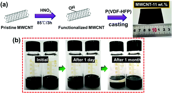
The unmodified MWCNTs were oxidized in nitric acid (HNO3). This process increases the defective sites and generates oxygen-containing groups on the surface of MWCNTs and hence enhances the reactivity of MWCNTs, as illustrated in Fig. 1a and b. Fig. 1b and Fig. S1 (ESI†) show the photographs of solution stability of the suspension with MWCNTs in DMF solution. The solution remained stable and dispersed in DMF solution over a month, confirming the –OH has been grafted onto the MWCNTs successfully.42 The microscopic structures of MWCNTs were investigated by TEM as shown in Fig. 2a and b, and the diameter of the MWCNTs was about 10–20 nm. As shown in Fig. 2c, the surface chemical structures of MWCNTs oxidized by HNO3 were further investigated by FTIR spectra. The wide absorption band at 1570–1700 cm−1 was attributed to MWCNTs. The broad band at 3420 cm−1 was in stretch mode O–H, which is caused by physically adsorbed water (OH).43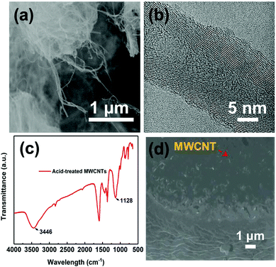 | ||
| Fig. 2 (a) SEM images of MWCNTs. (b) TEM micrograph of MWCNTs. (c) FTIR spectra of acidified MWCNTs and (d) cross-section SEM image of MWNT/PVDF composite with MWCNT mass fraction of 7%. | ||
Then, P(VDF-HFP) powder was dissolved in the above MWCNTs/DMF solution, and the composite film was prepared by the simple ultra-sonication-assisted solution casting method. Fig. 1a and Fig. S2 (ESI†) show the optical images of the flexible and high-quality composite films (0.1%–11 wt%) with a large size of 5 × 6 cm. Further observing the cross-section SEM of the composite film (Fig. 2d), the acid-treated MWCNTs appeared as bright dots and were well dispersed and tightly embedded within the P(VDF-HFP) matrix. Such good compatibility of acid-treated MWCNTs with P(VDF-HFP) and quality of dispersion observed in SEM are related to the strong interactions. The H atoms provided by –OH group are positively charged, most likely indicating that H is able to have a strong noncovalent interaction with the F atoms in PVDF.
A series of tri-layered composites was prepared by sequentially casting three layers containing two outer layers with (7–11 wt%) acid-treated MWCNT contents and medium layer with PMMA (5 wt%). The succinct symbol of 7-5-7 has been used to represent the film with the acid-treated MWCNT mass fractions of 7, 9, and 11 wt% in the upper and bottom layers, and a fixed PMMA mass fraction of 5 wt% in middle layer. The microscopic morphologies, layer architecture and thicknesses of central layers and neighboring layers of the films were further investigated by the cross-section images, as shown in Fig. 3a. Due to the chemical compatible effect between the amorphous PMMA and semi-crystalline P(VDF-HFP), the interfaces were tightly integrated without visible pores and the presence of voids, thus leading to dense ternary tri-layer composite films.44 The optical image of the flexible and high-quality ternary tri-layer composite film with a large size of 6 × 4 cm is presented in Fig. 3b.
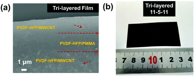 | ||
| Fig. 3 (a) Cross-section SEM image of the tri-layered composite film with 11 wt% MWCNT and (b) a photograph of the tri-layered composite film. | ||
3.2. Microstructure of the tri-layered composite
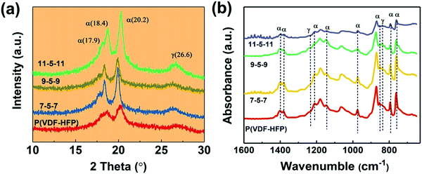
The XRD patterns of pure PVDF-HFP and tri-layered composite films are shown in Fig. 4. It can be seen that all these films exhibit peaks at 2θ =17.9, 18.4 and 20.2, which correspond to the α-phase,45 and the broad peak at 26.6 corresponds to the superposition of the γ-phase diffraction. For the tri-layered composite system, the peak of the α-phase at 2θ =18.4 and 26.6 is weakened after the introduction of the MWCNTs. In the meantime, the diffraction peak is slightly shifted up at a 0.2° increment for the 11-5-11 sample. The FT-IR spectra in Fig. 4b also confirm the unvaried crystal phase. The characteristic absorption bands of the α-phase were detected at 1403 cm−1, 1382 cm−1, 1211 cm−1, 1147 cm−1, 974 cm−1, 854 cm−1, 795 cm−1 and 763 cm−1 in the ternary tri-layered architecture films and PVDF-HFP films.46 And the peaks at 1234, 838 cm−1 correspond to γ-phase. No obvious peaks of β are detected.3.3. Dielectric properties of the tri-layered composite
We firstly investigated the frequency dependence of the dielectric properties of the single layer MWCNT/P(VDF-HFP) composites, as plotted in Fig. S3 (ESI†). It is clear that the content of MWCNT plays a critical role in determining dielectric behaviors of composites. It is also worth noting that the dielectric properties of the MWNT/P(VDF-HFP) composites show similar trend over the whole frequency range (1 kHz to 10 MHz) as that of the pure P(VDF-HFP) below percolation threshold. A dielectric loss peak can be also observed at about 10 MHz (see Fig. S3b, ESI†), which may be attributed to the dielectric relaxation in the P(VDF-HFP) matrix.47 Once above the percolation threshold, the variation of corresponding dielectric performance is very obvious. For instance, permittivity increased mildly, i.e. from 10 for pristine P(VDF-HFP) to 43.6 for composite with 7 wt% MWCNT at 1 kHz, while the dielectric loss is maintained at a low value (∼0.079) in this measured frequency, which is also presented in Fig. S4a (ESI†). In stark contrast, with further increasing content of MWCNT, permittivity in the measured frequency range and corresponding dielectric loss increase obviously at 1 kHz for the 9 wt% and 11 wt% films. The abrupt changes in permittivity and dielectric loss may be primarily ascribed to the formed conductive network and larger leakage currents resulting from the higher conductivity when the filler content of the composites approaches the percolation threshold. These results have been verified by the data of frequency dependent alternate current (AC) conductivity, as shown in Fig. S4b (ESI†). The electrical conductivity in the composite film with 7 wt% MWCNT is 1.87 × 10⁻⁵ S m−1, suggesting their favorable electrical insulation properties. Furthermore, the AC conductivity increases mildly to 3.07 × 10⁻⁵ S m−1 with the increase of the filler content to 9 wt%. In comparison, the higher conductivity (1.19 × 10⁻⁴ S m−1) of the composite approaches the percolation threshold, which can be observed in the insert of Fig. S4b (ESI†).Fig. 5a shows the permittivity of single layer and tri-layered architecture films as a function of frequency, over the range from 1 kHz to 10 MHz. With the increasing frequency, permittivity of all ternary tri-layered polymer films tends to decrease. It can be seen that significant increases in permittivity are observed with increasing MWCNT loading of the outer layer, while the dielectric loss remains at a low value (Fig. 5b) even for the composite approaching the percolation threshold. Apparently, all ternary tri-layered polymer films have much lower dielectric loss than single layer films with identical filler content over the whole frequency range (1 kHz to 10 MHz), which is important for film capacitor applications in preventing the self-heating of dielectrics. Fig. 6 shows the permittivity and dielectric loss of the single layer and tri-layered composite films at 1 kHz as a function of MWCNT content. The dielectric loss of the ternary tri-layered architecture film (11-5-11) is 0.14 even when the outer layer contains 11 wt% fillers at 1 kHz, while the dielectric loss of the single-layered film is 4. The low dielectric loss could be attributed to the following explanation: (i) the formation of hydrogen bonds could effectively promote the homogeneous distribution of MWCNT and the strong interfacial adhesion in the P(VDF-HFP) matrix, (ii) poly(methyl methacrylate) (PMMA)/P(VDF-HFP) blends can effectively suppress dielectric losses caused by linear dielectric PMMA mitigating the relaxation phenomenon of ferroelectric polymer, and (iii) due to the chemical compatibility and tight interfaces between adjacent layers, the tri-layered-structured films have been more effective in suppressing dielectric loss in comparison with single layer composites with an identical content of MWCNT.
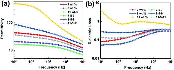 | ||
| Fig. 5 (a) Dependence of the permittivity and (b) dielectric loss of the single layer and tri-layered composite films. | ||
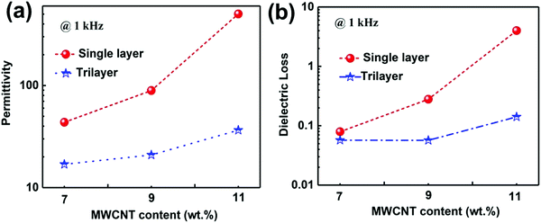 | ||
| Fig. 6 (a) Permittivity and dielectric loss of the single layer and tri-layered composite films at 1 kHz as a function of MWCNT content. | ||
For comparison with the dielectric capabilities of other previously reported polymer composites, the corresponding filler content, permittivity, dielectric loss and fabrication process are listed in Table 1.48–56 Obviously, high permittivity can be obtained in single layer composites introduced with BT, CCTO and Ni. However, these composites, due to high filler content in composites with ceramic nanofiller and high dielectric loss in percolative composites, have several inevitable drawbacks, such as poor mechanical flexibility and overheating. In particular, higher permittivity can be obtained in the tri-layered composite film when compared with most of the nanocomposites based on MWCNTs as fillers. It is shown that the tri-layered composite film with a low filler content manifests high permittivity, low dielectric loss, and great mechanical flexibility, which is realized via a simple ultra-sonication-assisted solution-casting method.
| Nanocomposites | Filler content | Dielectric constant | Dielectric loss | Fabrication technique |
|---|---|---|---|---|
| BT: barium titanate BaTiO3; MWCNT: multi-walled carbon nanotubes; POSS: polyhedral oligomeric silsesquioxane; PEN: poly(arylene ether nitrile); GO-e-CNT: graphene oxide-encapsulated carbon nanotube; PU: polyurethane. | ||||
| BT-np/PVDF-CTFE ref. 34 | 50% (volume) | 37 (1 kHz) | 0.07 | Ball-milled, spin-coating |
| BT-nw/PVDF ref. 48 | 10% (volume) | 49 (100 Hz) | 0.65 | Ultra-sonication, solution-casting |
| Ni/PVDF ref. 49 | 27% (volume) | 210 (1 kHz) | 0.25 | Physical blending, hot-press |
| CCTO/PVDF ref. 50 | 55% (volume) | 77.5 (1 kHz) | 0.11 | Melt-mixed, hot-press |
| La-CCTO/PVDF ref. 51 | 10% (mass) | 31 (100 Hz) | 0.35 | High temperature extrusion, hot-press |
| POSS@CNT/PVDF ref. 52 | 5% (mass) | 50 (1 kHz) | 0.7 | Ultra-sonication, solution-casting |
| MWCNT/PVDF ref. 53 | 1.6% (volume) | 50 (1 kHz) | 0.4 | Physical blending, hot-molding |
| MWCNT@SiO2/PEN ref. 54 | 3% (mass) | 8 (1 kHz) | 0.06 | Ultra-sonication, solution-casting |
| GO-e-CNT–PU ref. 55 | 5% (mass) | 11 (1 kHz) | 0.1 | Ultra-sonication, hot-press |
| TiO2@MWCNTs/PVDF ref. 56 | 0.1 (mass) | 15 (1 kHz) | 0.1 | hydrothermal process, solution-casting |
| Tri-layered nanocomposite | 9% (mass) | 21 (1 kHz) | 0.05 | Solution-casting |
| This work | 11% (mass) | 36.5 (1 kHz) | 0.14 | Solution-casting |
3.4. Mechanical durability of the tri-layered composite
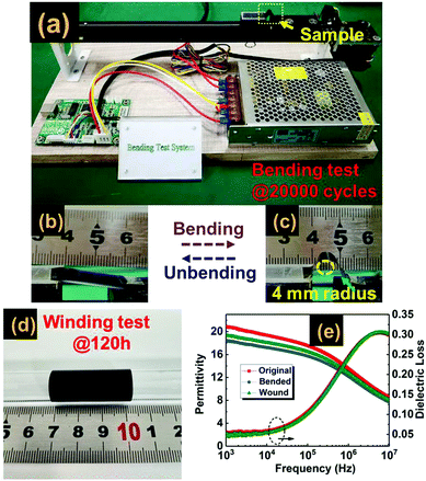
The mechanical flexibility and robustness against bending deformations of dielectric materials are important abilities of wound film capacitor cells.57,58 In order to demonstrate the mechanical flexibility and durability of the tri-layered composite, the winding test is adopted, in which a tri-layered film strip is wrapped on a glass tube with 2 mm diameter and the coiled state is held for 120 hours, as shown in Fig. 7(d). The second test is the bending test, in which we bend and unbend a tri-layered film strip repeatedly at a bending curvature of 4 mm radius over straight 20![[thin space (1/6-em)]](https://www.rsc.org/images/entities/char_2009.gif) 000 cycles. Each cycle is programmed to be accomplished in 5 seconds, as plotted in Fig. 7(a)–(c). The dielectric stability of the wound and bended samples was investigated by frequency dependent dielectric properties. The results of Fig. 7(e) indicate that both the wound and bended samples possess dielectric properties similar to those of the original material.
000 cycles. Each cycle is programmed to be accomplished in 5 seconds, as plotted in Fig. 7(a)–(c). The dielectric stability of the wound and bended samples was investigated by frequency dependent dielectric properties. The results of Fig. 7(e) indicate that both the wound and bended samples possess dielectric properties similar to those of the original material.
4. Conclusions
In summary, construction of a ternary tri-layered structure film with excellent dielectric properties and mechanical endurance is reported, which is composed of two outer layers of acid-treated MWCNT dispersed in the P(VDF-HFP) matrix and a middle layer of PMMA dispersed in the P(VDF-HFP) matrix by a facile layer-by-layer solution-casting technique. Owing to the successful formation of hydroxylation of MWCNTs, the composite powder can be uniformly dispersed in the matrix of P(VDF-HFP). Consequently, the tri-layered-structure nanocomposites with tight interfaces are capable of balancing the contradicted parameters, including permittivity, dielectric loss, and mechanical reliability, to endow excellent capacitive performance exceeding those of previously reported polymer dielectrics. The ternary tri-layered film with an optimized filler content (9 wt%) exhibited a high permittivity of 21 and a quite low dielectric loss of 0.05. Moreover, the results of mechanical tests (including bending and winding) show that the composite retained mechanical flexibility and capacitor stability after rigorous cycles. Therefore, such multilayer structure composites with functional fillers have potential applications in film capacitors due to ease of processability, good flexibility, high permittivity, and low dielectric loss.Conflicts of interest
There are no conflicts to declare.Acknowledgements
H. W. acknowledges the support of Shezhen Science and Technology Program (No. KQTD20180411143514543 and JCYJ20180504165831308) and Shenzhen DRC project [2018]1433.References
- C. W. Nan, Y. Shen and J. Ma, Annu. Rev. Mater. Res., 2010, 40, 131 CrossRef.
- Y. Wu, X. Y. Lin, X. Shen, X. Y. Sun, X. Liu, Z. Y. Wang and J. K. Kim, Carbon, 2015, 89, 102–112 CrossRef.
- Z. M. Dang, J. K. Yuan, S. H. Yao and R. J. Liao., Adv. Mater., 2013, 25, 6334–6365 CrossRef PubMed.
- B. C. Luo, X. H. Wang, Y. P. Wang and L. T. Li, J. Mater. Chem. A, 2014, 2, 510–519 RSC.
- Y. Zhao, Q. Liao, G. Zhang, Z. Zhang, Q. Liang, X. Liao and Y. Zhang, Nano Energy, 2015, 11, 719–727 CrossRef.
- H. Luo, X. F. Zhou, C. Ellingford, Y. Zhang, S. Chen, K. C. Zhou, D. Zhang, C. R. Bowen and C. Y. Wan, Chem. Soc. Rev., 2019, 48, 4424–4465 RSC.
- H. Luo, S. Chen, L. H. Liu, X. F. Zhou, C. Ma, W. W. Liu and D. Zhang, ACS Sustainable Chem. Eng., 2019, 7, 3145–3153 CrossRef.
- Y. Lin, C. Sun, S. L. Zhan, Y. J. Zhang and Q. B. Yuan, Adv. Mater. Interfaces, 2020, 2000033 CrossRef.
- X. J. Zhang, G. S. Wang, Y. Z. Wei, L. Guo and M. S. Cao, J. Mater. Chem. A, 2013, 1, 12115–12122 RSC.
- Y. Feng, W. L. Li, J. P. Wang, J. H. Yin and W. D. Fei, J. Mater. Chem. A, 2015, 3, 20313–20321 RSC.
- H. Tang and H. A. Sodano, Nano Lett., 2013, 13, 1373–1379 CrossRef CAS PubMed.
- Y. Wang, X. Zhou, Q. Chen, B. Chu and Q. Zhang, IEEE Trans. Dielectr. Electr. Insul., 2010, 17, 1036 CAS.
- Y. Q. Chen, B. P. Lin, X. Q. Zhang, J. C. Wang, C. W. Lai, Y. Sun, Y. R. Liu and H. J. Yang, J. Mater. Chem. A, 2014, 2, 14118–14126 RSC.
- F. X. Guan, J. Wang, J. L. Pan, Q. Wang and L. Zhu, Macromolecules, 2010, 43, 6739–6748 CrossRef.
- W. M. Xia, Z. Xu, F. Wen, W. J. Li and Z. C. Zhang, Appl. Phys. Lett., 2010, 97, 222905 CrossRef.
- C. C. Wang, J. X. Zhang, S. B. Gong and K. L. Ren, J. Appl. Phys., 2018, 124, 154103 CrossRef.
- S. D. Liao, Z. H. Shen, H. Pan, X. Zhang, Y. Shen, Y. H. Lin and C. W. Nan, J. Mater. Chem. C, 2017, 5, 12777 RSC.
- Y. F. Wang, J. Chen, Y. Li, Y. J. Niu, Q. Wang and H. Wang,, J. Mater. Chem. A, 2019, 7, 2965 RSC.
- Y. J. Niu, Y. Bai, K. Yu, Y. Wang, F. Xiang and H. Wang, ACS Appl. Mater. Interfaces, 2015, 7, 24168–24176 CrossRef PubMed.
- Y. Song, Y. Shen, P. H. Hu, Y. H. Lin, M. Li and C. W. Nan, Appl. Phys. Lett., 2012, 101, 152904 CrossRef.
- S. H. Liu, S. X. Xue, W. Q. Zhang, J. W. Zhai and G. H. Chen, J. Mater. Chem. A, 2014, 2, 18040 RSC.
- J. Y. Li, L. Zhang and S. Ducharme, Appl. Phys. Lett., 2007, 90, 132901 CrossRef.
- K. Meeporn and P. Thongbai, Appl. Surf. Sci., 2019, 481, 1160–1166 CrossRef.
- W. Y. Li, Z. Q. Song, J. M. Zhong, J. Qian, Z. Y. Tan, X. Y. Wu, H. Y. Chu, W. Nie and X. H. Ran, J. Mater. Chem. C, 2019, 7, 10371–10378 RSC.
- L. K. Wu, W. F. Yuan, N. Hu, Z. C. Wang, C. L. Chen, J. H. Qiu, J. Ying and Y. Li, J. Phys. D: Appl. Phys., 2014, 47, 135302 CrossRef.
- E. Francis, H. U. Ko, J. W. Kim, H. C. Kim, N. Kalarikkal, K. Varughese, J. Kim and S. Thomas, J. Mater. Chem. C, 2018, 6, 8152 RSC.
- W. Y. Li, Z. Q. Song, J. Qian, Z. Y. Tan, H. Y. Chu, X. Y. Wu, W. Nie and X. H. Ran, Carbon, 2019, 141, 728–738 CrossRef.
- Z. M. Dang, M. S. Zheng and J. W. Zha, Small, 2016, 12, 1688–1701 CrossRef.
- J. J. Li, S. I. Seok, B. J. Chu, F. Dogan, Q. M. Zhang and Q. Wang, Adv. Mater., 2009, 21, 217 CrossRef.
- X. Y. Huang, L. Y. Xie, K. Yang, C. Wu, P. K. Jiang, S. T. Li, S. Wu, K. Tatsumi and T. Tanaka, IEEE Trans. Dielectr. Electr. Insul., 2014, 21, 480 Search PubMed.
- H. Tang, Y. Lin and H. A. Sodano, Adv. Energy Mater., 2013, 3, 451 CrossRef.
- J. J. Li, P. Khanchaitit, K. Han and Q. Wang, Chem. Mater., 2010, 22, 5350 CrossRef.
- P. Kim, S. Jones, P. Hotchkiss, J. Haddock, B. Kippelen, S. Marder and J. Perry, Adv. Mater., 2007, 19, 1001 CrossRef.
- P. Kim, N. M. Doss, J. P. Tillotson, P. J. Hotchkiss, M. J. Pan, S. R. Marder, J. Y. Li, J. P. Calame and J. W. Perry, ACS Nano, 2009, 3, 2581 CrossRef PubMed.
- P. H. Hu, Y. Shen, Y. H. Guan, X. H. Zhang, Y. H. Lin, Q. M. Zhang and C. W. Nan, Adv. Funct. Mater., 2014, 24, 3172 CrossRef.
- X. Huang and P. K. Jiang, Adv. Mater., 2015, 27, 546–554 CrossRef.
- Y. F. Wang, L. X. Wang, Q. B. Yuan, J. Chen, Y. J. Niu, X. W. Xu, Y. T. Cheng, B. Yao, Q. Wang and H. Wang, Nano Energy, 2018, 44, 364–370 CrossRef.
- Y. F. Feng, Q. Wu, Q. H. Deng, C. Peng, J. B. Hu and Z. C. Xu,, J. Mater. Chem. C, 2019, 7, 6744 RSC.
- H. J. Ye, X. H. Zhang, C. F. Xu, B. Han and L. X. Xu, J. Mater. Chem. C, 2018, 6, 11144–11155 RSC.
- Y. Cui, X. Wang, T. D. Zhang, C. H. Zhang and Q. G. Chi, RSC Adv., 2019, 9, 33229 RSC.
- B. C. Luo, X. H. Wang, H. X. Wang, Z. M. Cai and L. T. Li,, Compos. Sci. Technol., 2017, 151, 94–103 CrossRef.
- S. W. Kim, T. Kim, Y. S. Kim, H. S. Choi, H. J. Lim, S. J. Yang and C. R. Park, Carbon, 2012, 50, 3–33 CrossRef.
- W. Yan, Y. Zhang, H. W. Sun, S. W. Liu, Z. G. Chi, X. D. Chen and J. R. Xu,, J. Mater. Chem. A, 2014, 2, 20958 RSC.
- J. Chen, Y. F. Wang, Q. B. Yuan, X. W. Xu, Y. J. Niu, Q. Wang and H. Wang, Nano Energy, 2018, 54, 288–296 CrossRef.
- X. Lin, P. H. Hu, Z. Y. Jia and S. M. Gao, J. Mater. Chem. A, 2016, 4, 2314–2320 RSC.
- C. L. Liang, Z. H. Mai, Q. Xie, R. Y. Bao, W. Yang, B. H. Xie and M. B. Yang, J. Phys. Chem. B, 2014, 118, 9104–9111 CrossRef.
- R. Rama, M. Rahaman and D. Khastgir, Composites, Part A, 2015, 69, 30–39 CrossRef.
- Y. Feng, W. L. Li, Y. F. Hou, Y. Yu, W. P. Cao, T. D. Zhang and W. D. Fei, J. Mater. Chem. C, 2015, 3, 1250–1260 RSC.
- M. Panda, V. Srinivas and A. K. Thakur, Appl. Phys. Lett., 2008, 92, 132905 CrossRef.
- P. Thomas, K. T. Varughese, K. Dwarakanath and K. B. R. Varma, Compos. Sci. Technol., 2010, 70, 539–545 CrossRef CAS.
- A. Srivastava, P. Maiti, D. Kumar and O. Parkash, Compos. Sci. Technol., 2014, 93, 83–89 CrossRef CAS.
- W. J. Zhang, Z. Z. Zhou, Q. F. Li and G. X. Chen, Ind. Eng. Chem. Res., 2014, 53, 6699–6707 CrossRef CAS.
- L. Wang and Z. M. Dang, Appl. Phys. Lett., 2005, 87, 042903 CrossRef.
- F. Jin, M. N. Feng, X. Huang, C. Long, K. Jia and X. B. Liu, Appl. Surf. Sci., 2015, 357, 704–711 CrossRef CAS.
- C. Wu, X. Y. Huang, X. F. Wu, L. Y. Xie, K. Yang and P. K. Jiang, Nanoscale, 2013, 5, 3847–3855 RSC.
- L. Yang, J. H. Qiu, H. L. Ji, K. J. Zhu and J. Wang, Composites, Part A, 2014, 65, 125–134 CrossRef CAS.
- Q. Li, L. Chen, M. R. Gadinski, S. H. Zhang, G. Z. Zhang, H. Y. Li, A. Haque, L. Q. Chen, T. Jackson and Q. Wang, Nature, 2015, 523, 576 CrossRef CAS.
- Z. Wang, T. Wang, C. Wang, Y. J. Xiao, P. P. Jing, Y. F. Cui and Y. P. Pu, ACS Appl. Mater. Interfaces, 2017, 9, 29130–29139 CrossRef CAS.
Footnote |
| † Electronic supplementary information (ESI) available. See DOI: 10.1039/d0tc00148a |
| This journal is © The Royal Society of Chemistry 2020 |

