
 Open Access Article
 This Open Access Article is licensed under a Creative Commons Attribution-Non Commercial 3.0 Unported Licence
The effect of nanoscaffold porosity and surface chemistry on the Li-ion conductivity of LiBH4–LiNH2/metal oxide nanocomposites†
Laura M.
de Kort
 ,
Justine
Harmel
,
Petra E.
de Jongh
and
Peter
Ngene
*
,
Justine
Harmel
,
Petra E.
de Jongh
and
Peter
Ngene
*
Inorganic Chemistry and Catalysis Debye Institute for Nanomaterials Science, Utrecht University, Universiteitsweg 99, 3584CG Utrecht, the Netherlands. E-mail: P.Ngene@uu.nl
First published on 14th September 2020
Abstract
Solid-state electrolytes are crucial for the realization of safer batteries with improved capacity. Lithium-based complex hydrides, for instance LiBH4, display promising characteristics as solid-state electrolytes. However, increasing their low room temperature conductivity (10−8 S cm−1 for LiBH4) is a prerequisite for application. Partial ionic substitution of BH4− with NH2− followed by nanoconfinement in mesoporous oxide scaffolds increases the conductivity to 5 × 10⁻⁴ S cm−1. Here, we show that the conductivity of LiBH4–LiNH2/metal oxide nanocomposites is strongly influenced by the chemical and physical nature of the scaffold material. By tuning both the surface chemistry and the pore structure, the conductivity can be varied by three orders of magnitude at room temperature. Unexpectedly, even though a significant influence of the scaffold surface chemistry is observed, the nanocomposite conductivity is largely dictated by the scaffold pore volume. This is in contrast to nanoconfined pure LiBH4, where the conductivity is governed by the chemical nature of the mesoporous scaffold. For nanoconfined LiBH4–LiNH2, the conductivity improvement is attributed to stabilization of a highly conductive phase inside the scaffold pores, rather than the formation of a conductive interfacial layer at the oxide/hydride interface as observed for nanoconfined LiBH4. These findings could be applicable to other cation- and anion-substituted nanocomposites and provide a useful tool to develop novel solid-state electrolytes with excellent ionic conductivities.
Introduction
Next generation batteries, such as all-solid-state (ASS) batteries, could play a key role in meeting the world's energy storage demands. Both the progressive depletion of fossil fuels and the United Nations' sustainable development goals call for a transition to renewable energy sources. Most renewables, in particular wind and solar energy, are intermittent in nature and, consequently, an increased use of renewable energy calls for improved energy storage devices.1–3 All-solid-state batteries are expected to be one of the key storage technologies, both for mobile applications as well as large-scale grid storage.1,4 Hence, this battery type could be essential for the transition from fossil fuels to renewable energies.All-solid-state batteries contain an inorganic or polymeric solid as the electrolyte instead of a solution of an ion conducting salt in organic solvent as is the case for conventional Li-ion batteries. Solid electrolytes are often safer than the volatile and combustible liquid electrolytes, and in many cases they are compatible with high capacity electrodes.5,6 This means that the development of ASS batteries can potentially lead to safer batteries that store more energy.
Solid-state electrolytes with good ionic conductivity at ambient temperature as well as good electrochemical stability are crucial for the implementation of ASS batteries. Various classes of materials, including garnets, sulphides, perovskites and complex hydrides, are being investigated as potential solid electrolyte for ASS batteries.7–11 Over the past years research has largely focussed on the development of suitable oxide and sulphide-type ion conductors. However, the discovery of unexpectedly fast ion conduction in lithium borohydride initiated research on complex hydride-based solid electrolytes.12–18 Essential to this development was the observation of high lithium-ion mobility (∼10−3 S cm−1) in LiBH4 after a reversible phase change from orthorhombic to hexagonal phase at 110 °C.14 Due to their low density, a good electrochemical stability window (up to ∼3 V vs. Li/Li+) and the ability to form a good interface with electrode materials, complex hydrides are promising candidates for application in ASS batteries.19–22 A main disadvantage remains their moderate room temperature ionic conductivity (for LiBH4 about 10−8 S cm−1). Therefore, the development of strategies that enhance conductivity in complex hydrides at ambient temperature is of major importance.
Two promising strategies are being explored. The most common method, partial ionic substitution, is based on replacing some borohydride anions with different anions (e.g. I−, Cl− or NH2−).23–31 This leads to stabilization of the highly conductive hexagonal phase at lower temperatures (e.g. for I−, Cl−)25,30 and/or the formation of a new highly conductive phase (e.g. for NH2−).27,29 Similarly, successful enhancement of conductivity has been achieved through partial cationic substitution of Li+ by, for example, K+, Ca2+ and La3+.32–34 The incorporation of a substituting anion increases the distance between neighbouring BH4− ions, weakens the Coulomb interactions and consequently results in enhanced Li-ion mobility.
In the second method, the lithium salt is intimately mixed with a high surface area non-conducting oxide scaffold, such as SiO2 or Al2O3.35–44 Close contact can be achieved through nanoconfinement by melt infiltration of the metal hydride in the nanopores of the oxide, thereby forming a nanocomposite.45 Interestingly, this method was originally used to improve hydrogen sorption properties of metal hydrides.46–50 Recently, it was discovered that it leads to enhanced Li-ion mobility as well.35 The enhancement in ionic conductivity is attributed to the formation of a highly conductive interface layer at the interface of the ion-conducting salt and the insulating scaffold. In general, it is believed that the interaction of the hydride with the scaffold either leads to the formation of a new compound, or a highly defected phase, or that interfacial space charge zones play a role as observed in binary mixtures of metal halides (LiI, LiBr, AgI, etc.) and metal oxides.39,51,52
Recently, both methods, viz. partial ionic substitution and nanoconfinement, were successfully combined. In fact, via the synthesis of nanoconfined anion-substituted complex hydrides, such as nanoconfined LiBH4–LiI and LiBH4–LiNH2, conductivity could be substantially improved.53–55 Although the increased conductivity in the anion-substituted/oxide nanocomposites was attributed to the synergetic effect of anion substitution and confinement in the oxide nanopores, the exact role of the confinement remained unclear. For nanocomposites with pure complex hydrides, e.g. LiBH4/SiO2, it is known that their ionic conductivity is greatly affected by the surface properties of the scaffold, such as the nature and density of the surface groups.40–44 For nanoconfined anion-substituted metal hydrides, on the other hand, the impact of the mesoporous scaffold properties on the scaffold/hydride interactions, and consequently ion mobility in the nanocomposites, have not yet been investigated.
In this work, we aim to bridge the knowledge gap by studying the effect of the chemical nature and physical properties (surface area, pore size and pore volume) of different porous, high surface area materials, on the conductivity of LiBH4–LiNH2/oxide nanocomposites. To this end, we prepared nanoconfined LiBH4–LiNH2 using SiO2 scaffolds with varying pore structure and surface properties, as well as mesoporous γ-Al2O3, and studied the influence of the scaffold's properties on the conductivity.
Experimental
Scaffold synthesis
Mesoporous silica (MCM-41 and SBA-15) and aluminated silica (Al-SBA-15) were synthesized following the procedures described by Cheng et al.,56 Lee et al.57 and Baca et al.58 A complete description of the experimental procedures can be found in the ESI.† Note that Al-SBA-15 with a Si/Al ratio of 20![[thin space (1/6-em)]](https://www.rsc.org/images/entities/char_2009.gif) :1 and 10:1 were prepared, further referred to as Al(20)- and Al(10)-SBA-15. Alumina (γ-Al2O3, Puralox SCCa-5/200, >98.0%) was purchased from Sasol. All scaffolds were dried under vacuum at 150–250 °C overnight and transferred to an argon-filled glovebox before use.
:1 and 10:1 were prepared, further referred to as Al(20)- and Al(10)-SBA-15. Alumina (γ-Al2O3, Puralox SCCa-5/200, >98.0%) was purchased from Sasol. All scaffolds were dried under vacuum at 150–250 °C overnight and transferred to an argon-filled glovebox before use.
Nanocomposite synthesis
Nanocomposites were prepared via a two-step synthesis consisting of the preparation of LiBH4–LiNH2 phase mixtures followed by melt infiltration of the as-prepared phase mixture. All storage and handling of the chemicals and prepared samples was done in an argon-filled glovebox (H2O & O2 < 0.1 ppm).Several LiBH4–LiNH2 phase mixture were prepared by physically mixing LiBH4 (≥95%, Sigma-Aldrich) and 5, 15, 25, 30, 40, 50, 67 and 75 molar percentage of LiNH2 (95%, Sigma-Aldrich). The physical mixture was transferred to a stainless-steel reactor which is then placed in a stainless-steel high-pressure autoclave (Parr, 250 mL). The mixture was allowed to react at 150 °C (heating rate 2.5 °C min−1) under 50 bar H2 pressure for 30 minutes. After the reaction, the formed phase mixture was ground to fine powders.
Preparation of the LiBH4–LiNH2/metal oxide nanocomposites and LiBH4/metal oxide nanocomposites was achieved via melt infiltration following the procedure of Ngene et al.48 In general, the LiBH4–LiNH2 phase mixture (or pure LiBH4) was mixed with the appropriate amount of the chosen scaffold in order to fill the scaffold pores by (typically) 130 volume percent. In this way, the LiBH4 content is 30 vol% larger than the total pore volume of the scaffold material. This ensures a percolating network of fast Li+ diffusion pathways over the non-conducting oxide particles. In other words, Li+ transport occurs through the metal hydride phase, not through the oxide. The corresponding molar and mass fractions of the composites are provided in Table S1.† The mixture was transferred to a stainless-steel reactor, which was placed in a stainless-steel high-pressure autoclave (Parr, 250 mL). The autoclave was pressurized with 50 bar H2 and melt infiltration was carried out for 30 minutes at 120 °C (heating rate 2.5 °C min−1) for LiBH4–LiNH2 and at 285 °C for LiBH4. Upon cooling, the molten LiBH4–LiNH2 mixture solidifies in the pores of the scaffold material to form nanoconfined LiBH4–LiNH2 or nanoconfined LiBH4.
General characterization
X-ray diffraction (XRD) was performed with a Bruker-AXS D8 Advance X-ray diffractometer with Co Kα1,2 radiation (λ = 1.78897 Å). The samples were placed in an airtight sample holder. Diffractograms were recorded at room temperature from 20 to 80° 2θ. Diffuse reflectance infrared Fourier transform spectroscopy (DRIFTS) measurements were performed on a PerkinElmer 2000 spectrometer equipped with a MCT detector. The sample was placed in an airtight sample holder with KBr windows. Spectra were acquired from 900 cm−1 to 4500 cm−1 with a resolution of 4 cm−1. Differential scanning calorimetry (DSC) was conducted using a Mettler Toledo HP DSC 1-STAR. About 10 mg of sample was placed in a 40 μL Al sample pan. The measurement was performed under 2 bar Ar pressure and an Ar flow of 10 mL min−1. The samples were cycled between 30 °C and 300 °C with a heating rate of 5 °C min−1 and a cooling rate of 10 °C min−1. Nitrogen physisorption measurements were carried out at −196 °C on a Micrometritics TriStar II Plus Surface Area and Porosity analyser. No drying procedure was performed prior to the measurements, as all measured samples were stored under controlled atmosphere in an argon-filled glovebox. Analysis of the adsorption and desorption curves was performed following Brunauer, Emmett and Teller (BET) theory and Barrett, Joyner and Halenda (BJH) theory to determine surface area and pore size distribution, respectively.59,60Conductivity measurements
Electrochemical impedance spectroscopy measurements were performed using a Princeton Applied Research Parstat 2273 connected to a custom-made measurement cell in a Büchi B-585 glass oven placed in an argon-filled glovebox to avoid air and moisture exposure. Symmetrical pellets were prepared by firstly placing lithium foils on top of two stainless steel cylinders (Ø = 13 mm). Using a standard pellet press, about 80–200 mg sample was pressed between these cylinders with a pressure of 1.5 ton cm−2. The same pressure was applied for all measurements to minimize differences in void fraction between pellets, which was generally below 20%. The prepared pellet was placed in the measurement cell. In a typical conductivity measurement, the pellet is incrementally heated to 50 °C (ΔT = 5 °C) and incrementally cooled to room temperature (ΔT = 10 °C). At each increment, the temperature was allowed to equilibrate for 35 min, after which an EIS measurement was performed using a 1.0 V RMS modulated AC potential with frequencies from 1 MHz to 1 Hz. The Nyquist plots obtained from the data were fitted using an equivalent circuit consisting of a resistance and a constant phase element. The intersection of the fitted semicircle with the Zreal axis was assumed to represent the electrolyte resistance R. See Fig. S1 and S2 in the ESI† for exemplary Nyquist plots of each studied system. Following σ = t/(AR), the conductivity σ of the solid electrolytes could be calculated using the electrolyte thickness t and geometric surface area A of the electrodes.Results and discussion
Partial ionic substitution of BH4− with NH2−
First, the structural properties of LiBH4–LiNH2 mixtures containing 15 to 67 mol% LiNH2 are discussed. The composition of all compounds in wt% is given in Table S1.† In Fig. 1a the XRD diffraction patterns of LiBH4–LiNH2 containing 15, 40 and 67% LiNH2 are presented. For comparison, the XRD patterns of LiBH4 and LiNH2 are included. A complete overview of the XRD data of all prepared LiBH4–LiNH2 mixtures can be found in Fig. S3.† The diffraction patterns of the mixtures clearly display features that do not correspond to the starting materials. New reflections are observed, which correspond to the presence of several LiBH4–LiNH2 phases, such as Li2(BH4)(NH2), Li3(BH4)(NH2)2 and Li4(BH4)(NH2)3. This is in accordance with previously reported results.27,29,61–63 Meisner et al. identified four different LiBH4–LiNH2 phases with different lattice symmetry and varying melting points of ∼45 °C (γ-phase), 75–90 °C (β-phase), 150–190 °C (α-phase) and ∼50 °C (δ-phase).62 In our case, the presence of multiple phases in most LiBH4–LiNH2 mixtures is clearly observed as well. The formation of LiBH4–LiNH2 phases as demonstrated by XRD is further corroborated with differential scanning calorimetry (DSC) and diffuse reflectance infrared Fourier transform spectroscopy (DRIFTS) as shown in Fig. 1b and S4,† respectively. | ||
| Fig. 1 (a) XRD powder patterns and (b) DSC graphs of LiBH4–LiNH2 phase mixtures containing between 15 and 67 mol% LiNH2. For comparison, XRD patterns of pure LiBH4 and LiNH2 are included. Reflections related to Li2(BH4)(NH2) and Li4(BH4)(NH2)3 are indicated by the dashed and straight lines, respectively. | ||
With differential scanning calorimetry, different LiBH4–LiNH2 phases can be distinguished by their specific phase transition (melting) temperature. In Fig. 1b the DSC curves of LiBH4–LiNH2 phase mixtures containing 15 to 67 mol% LiNH2 are shown. The DSC results reveal that up to three different LiBH4–LiNH2 phases are formed in the prepared LiBH4–LiNH2 mixtures. For compositions with 30 mol% LiNH2 or less, the presence of unreacted LiBH4 is reflected by an endothermic peak around 110 °C due to the phase transition from orthorhombic to hexagonal LiBH4. Melting of the γ- and β-phase in the LiBH4–LiNH2 mixtures is revealed by endothermic peaks at 45 °C and 90–110 °C, respectively. Notably, for compositions containing 40 mol% LiNH2 or more, the presence of LiBH4 is no longer observed, while a third peak attributed to melting of the α-phase is identified between 120 °C and 220 °C. With increasing amount of LiNH2 the area of this peak increases, indicating that the amount of the α-phase increases. The peak also shifts to higher temperatures, which can be ascribed to the formation of a more stable LiBH4–LiNH2 compound with increasing LiNH2 content. To summarize, in line with the results described by Meisner et al. both XRD and DSC reveal the formation of new LiBH4–LiNH2 phases.62 Note here that the composition and thereby the melting temperature of the prepared LiBH4–LiNH2 mixture depends on the molar fraction of LiNH2. The melting point of the LiBH4–LiNH2 mixture plays a key role in the preparation of nanoconfined LiBH4–LiNH2 through melt infiltration as will be discussed in the following section.
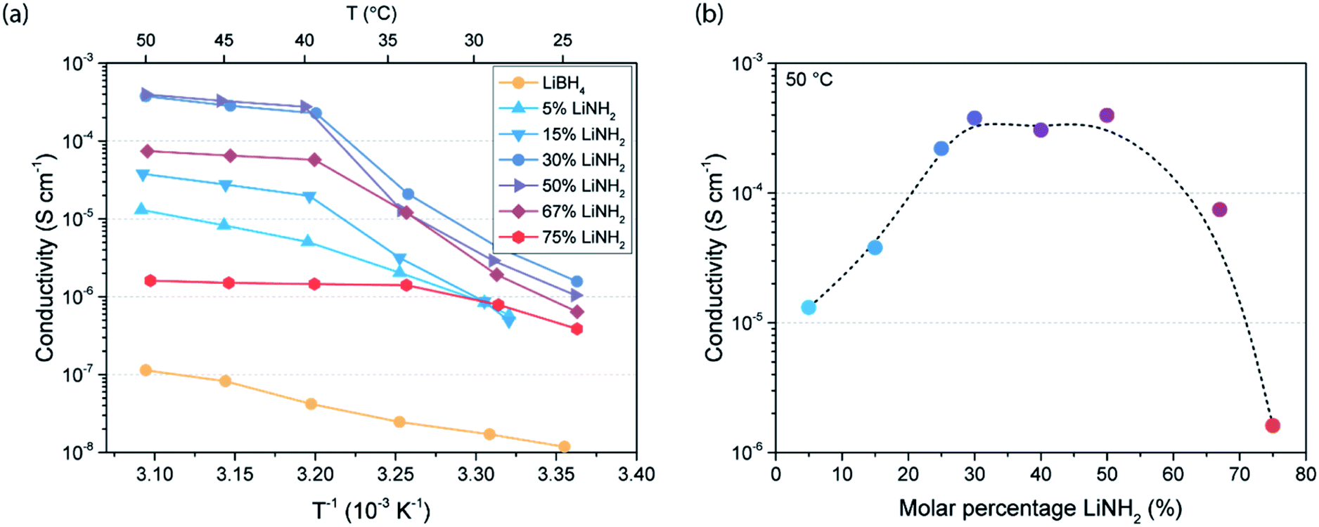
The effect of partial ionic substitution with LiNH2 on the conductivity of LiBH4 is analysed by recording the complex impedance of the LiBH4–LiNH2 mixtures over a range of temperatures. Previous studies have mainly focussed on the conductivity of LiBH4–LiNH2 with a high LiNH2 content, i.e. 50, 67 and 75 mol% LiNH2.27,29 In this study, the conductivity is determined for LiBH4–LiNH2 mixtures containing 5 to 75 mol% LiNH2. The conductivity data as derived from the complex impedance analysis are displayed in Fig. 2a. Overall, an improvement in conductivity compared to pure LiBH4 is seen for all LiBH4–LiNH2 mixtures. Generally, a sharp increase in conductivity with temperature is observed between 25 °C and 40 °C as was previously observed by Yan et al. for Li3(BH4) (NH2)2.29 The increased conductivity is related to melting of the LiBH4–LiNH2 γ-phase, as revealed by DSC in Fig. 1b. At temperatures above 40 °C the conductivity generally shows a negligible temperature dependence, suggesting a superionic conducting phase. To demonstrate the difference in conductivity between the different phase mixtures in this region, the conductivity at 50 °C for each LiBH4–LiNH2 composition is shown in Fig. 2b. In particular for LiBH4–LiNH2 containing 30 to 50 mol% LiNH2 a high conductivity is observed, reaching about 4 × 10⁻⁴ S cm−1 at 50 °C. Notably, in LiBH4–LiNH2 with a lower LiNH2 content (less than 30%) unreacted LiBH4 is present, while materials with a higher LiNH2 content (above 50%) predominantly contain the LiBH4–LiNH2 α-phase (Fig. 1b). It is apparent that the presence of unreacted LiBH4- or α-phase reduces the overall conductivity, in contrast to the LiBH4–LiNH2 γ- and β-phase that are beneficial for a higher conductivity. Consequently, an optimum in conductivity is achieved for LiBH4–LiNH2 containing 30 to 50 mol% LiNH2, lower than the LiNH2 content in the materials that were previously studied.
 | ||
| Fig. 2 (a) Arrhenius plots visualizing conductivity versus reciprocal temperature of LiBH4–LiNH2 solid electrolytes with 5 to 75 mol% LiNH2 as well as pure LiBH4. (b) Conductivity dependence on LiNH2 content in the LiBH4–LiNH2 phase mixtures. The dashed line is added to guide the eye and has no physical meaning. | ||
Nanoconfinement of LiBH4–LiNH2 in mesoporous SiO2 scaffold
The effect of nanoconfinement in mesoporous MCM-41 (SiO2) on the structure and conductivity of LiBH4–LiNH2 is discussed specifically for the mixtures containing 30 to 50 mol% LiNH2, as these compositions had the highest conductivities. To start, we discuss the structural changes and effectiveness of the synthesis method, i.e. incorporation of the metal hydride in the pores of the mesoporous oxide, as observed by DRIFTS. In Fig. 3a the DRIFTS absorbance spectra of the prepared nanocomposites as well as MCM-41 are visualized. The spectra of the corresponding LiBH4–LiNH2 phase mixtures are provided in Fig. S4.† In the DRIFTS spectra three regions of interest are identified. First, macrocrystalline LiBH4 typically displays three characteristic bands between 2000 and 2800 cm−1, corresponding to the [BH4−] stretching vibrations.64 The nanocomposite spectra contain a broad band in this region. The broadening effect was observed in previous studies on nanoconfined LiBH4, and was attributed to increased rotational freedom of the [BH4−] anion due to the structural changes induced by nanoconfinement.43 Secondly, two sharp bands related to [N–H] stretching vibrations of LiNH2 are typically present at 3260 and 3310 cm−1.65 In the nanocomposites spectra, these sharp peaks are no longer observed. Instead, a broad peak at a slightly higher wavenumber (3000–3500 cm−1) is seen. Similar to the observations on [BH4−], the broadening effect indicates an increased rotational freedom of the [NH2−] anion caused by structural changes upon nanoconfinement. Likewise, the peak shift towards a higher wave number can be attributed to a change in the Li–N–H bonding due to interactions with the surface groups of the oxide scaffold, as reported for LiBH4 nanoconfined in Al2O3 and SiO2. | ||
| Fig. 3 (a) DRIFTS spectra of LiBH4–LiNH2/SiO2 nanocomposites. An enlargement is given of the region associated with hydroxyl stretching (3800–3700 cm−1). (b) Arrhenius plots visualizing conductivity versus reciprocal temperature of LiBH4–LiNH2 nanocomposites. | ||
The last region of interest is ascribed to the hydroxyl stretching vibration of the SiO2 silanol groups appearing around 3746 cm−1.66 Compared to the pure MCM-41 scaffold, this vibration almost completely disappears in nanoconfined LiBH4–LiNH2 with 30 to 50 mol% LiNH2. In previous studies it has been found that the silanol vibrations disappear when the pores of the scaffold are filled with an electrolyte salt, as the hydroxyl vibrations are supressed by interactions or reaction between the silanol groups and the confined electrolyte.43,48 This is clearly also the case for nanoconfined LiBH4–LiNH2, implying that for the used compositions, the melt infiltration process results in the successful incorporation of LiBH4–LiNH2 in the oxide pores. Further evidence for the incorporation of LiBH4–LiNH2 into the oxide pores is provided by XRD and N2 physisorption (Fig. S5†). The XRD diffraction pattern for the nanoconfined LiBH4-50% LiNH2 shows a complete loss of crystallinity, as expected for nanoconfined materials,50 while with N2 physisorption a loss in pore volume with increasing amount of LiBH4–LiNH2 is observed, consistent with successful infiltration of the metal hydride in the pores of the mesoporous oxide.48,50
The conductivity of the nanocomposites is shown in Fig. 3b. In general, ionic transport at temperatures below 40 °C increased by one to two orders of magnitude compared to the corresponding LiBH4–LiNH2 phase mixtures. Notably, the highest conductivity of 1 × 10⁻⁴ S cm−1 at 30 °C is achieved for LiBH4-40% LiNH2/MCM-41, close to ionic conductivities observed for state of the art solid electrolytes, such as thiophosphates.6,7 To compare, the conductivity is 40 times higher than the initial (non-confined) LiBH4–LiNH2, 5 times higher than nanoconfined LiBH4 and over 4 orders of magnitude higher than nanoconfined LiNH2 (Fig. S6†). Furthermore, over the recorded temperature range, no phase change-induced conductivity increase is identified, in contrast to non-confined LiBH4–LiNH2 that revealed a structural phase change leading to a highly conducting phase above 40 °C. This suggests that the observed conductivity enhancement might originate from another phenomenon, such as stabilization of the high conductivity LiBH4–LiNH2 phase at lower temperatures through nanoconfinement, in addition to the formation of a conductive interface layer as is the case for nanoconfined LiBH4.
The activation energy for long-range ion transport in the nanocomposites was derived from the slope in the Arrhenius plots. A summary of the activation energies is shown in Table 1. For the LiBH4–LiNH2/MCM-41 nanocomposites the activation energies vary from 0.51 (±0.01) eV to 0.80 (±0.03) eV, whereas the activation energy of the low temperature LiBH4–LiNH2 phase (between 25 and 35 °C) is 2.0 (±0.2) eV. Hence, in agreement with the enhancement in conductivity, the activation energy for ion transport has decreased upon nanoconfinement of LiBH4–LiNH2. Note that the activation energy of the high temperature (HT) LiBH4–LiNH2 phase (above 40 °C) is even lower, consistent with a molten phase in which the Li+-ions can move easily. This molten phase could be related to melting of LiBH4–LiNH2 γ-phase or the liquid phase LiBH4·(NH3)0.5 as described in a recent work by Yan et al.63 The variation in the activation energy for the different nanocomposites is due to the differences in composition of the nanoconfined LiBH4–LiNH2. As explained in the previous section, in each LiBH4–LiNH2 mixture different phase(s) are present, which has a consequence for the Li-ion dynamics within the materials. The higher activation energy of LiBH4-30% LiNH2/MCM-41 and LiBH4-50% LiNH2/MCM-41 compared to LiBH4-40% LiNH2/MCM-41 can be explained by the presence of unreacted LiBH4 and α-phase LiBH4–LiNH2 in the respective LiBH4–LiNH2 phase mixtures.
| Sample | E a (eV) | Pre-factor ln(A) |
|---|---|---|
| a E a low temperature (LT) phase determined from 25 °C to 35 °C. b E a high temperature (HT) phase determined from 40 °C to 50 °C. | ||
| LiBH4 – 50% LiNH2 (LTa/HTb) | 2.0 (±0.2)/0.32 (±0.02) | 3.6 (±0.6)/64 (±6) |
| LiBH4 – 30% LiNH2/MCM-41 | 0.59 (±0.01) | 12.6 (±0.1) |
| LiBH4 – 40% LiNH2/MCM-41 | 0.51 (±0.01) | 10.8 (±0.2) |
| LiBH4 – 50% LiNH2/MCM-41 | 0.80 (±0.03) | 21.9 (±0.9) |
Effects of the scaffold properties on nanocomposite conductivity
It is clear that the conductivities of the LiBH4–LiNH2 phase mixtures are significantly enhanced by nanoconfinement in the pores of mesoporous silica (MCM-41). For pure LiBH4, the enhancement in conductivity upon nanoconfinement in a mesoporous oxide has been attributed to the interactions between surface groups of the oxide and the confined metal hydride, which leads to the formation of a space-charge region or highly defected layer at the LiBH4/oxide interface.39,43,51 In this case, the chemical nature of the scaffold, especially the surface chemistry, is crucial for the interface effects, and thereby the conductivity of the LiBH4/oxide nanocomposite. Alternatively, it is also known that nanoconfinement can lead to a reduction in phase transition temperature, which can profoundly influence the properties of nanoconfined complex hydrides. This effect depends strongly on the pore structure of the mesoporous oxides, as described by the Gibbs–Thomson equation which shows an inverse relationship between the phase transition temperature of a confined material and the size of the confining pore.67 Hence, it is expected that the properties of the scaffold are important in determining the effect of confinement, and thereby the conductivity of the metal hydride nanocomposites.The impact of the chemical nature of the scaffold surface as well as the porosity on the nanocomposite conductivity was studied by preparing nanocomposites using SBA-15 (SiO2) scaffolds with varying surface chemistry and porosity. Similar to MCM-41, SBA-15 is a hexagonally shaped mesoporous silica. The reason for using SBA-15 in this study is that unlike MCM-41, the pore diameter and pore volume of SBA-15 can be readily tuned by changing the condensation temperature (Tc), while particle size, and thereby pore length, as well as surface area are not (significantly) affected.57,68,69 Moreover, using surface grafting techniques, such as surface alumination, the surface chemistry of SBA-15 can be altered. Hence, SBA-15 is a good model system to study the impact of both the physical and chemical properties of scaffolds on the conductivity of the nanocomposites.
For an accurate analysis of the role of interfacial interactions, the influence of other scaffold properties, such as morphology and porosity, should be minimal. For this purpose, aluminated (Al)-SBA-15, with Si/Al = 20 and 10, was prepared through surface alumination of conventional SBA-15. Upon alumination, the amount and chemical nature of surface hydroxyl groups is modified, which can be (qualitatively) observed in the DRIFTS spectra of the oxides provided in Fig. 4a. Here, the difference in vibrational energy of the surface hydroxyl groups on SBA-15, Al-SBA-15 and γ-Al2O3 is visualized. In general, the hydroxyl groups of aluminated SBA-15 and γ-Al2O3 exhibit a larger variety in vibrational energy compared to unmodified SBA-15. This is related to the difference in the chemical nature of the surface hydroxyl groups on the oxides. Typically, SiO2 (SBA-15) contains only weak Brønsted acidic silanol groups, while Al2O3, and consequently Al-SBA-15, contain Brønsted acidic and Brønsted basic sites.58,70
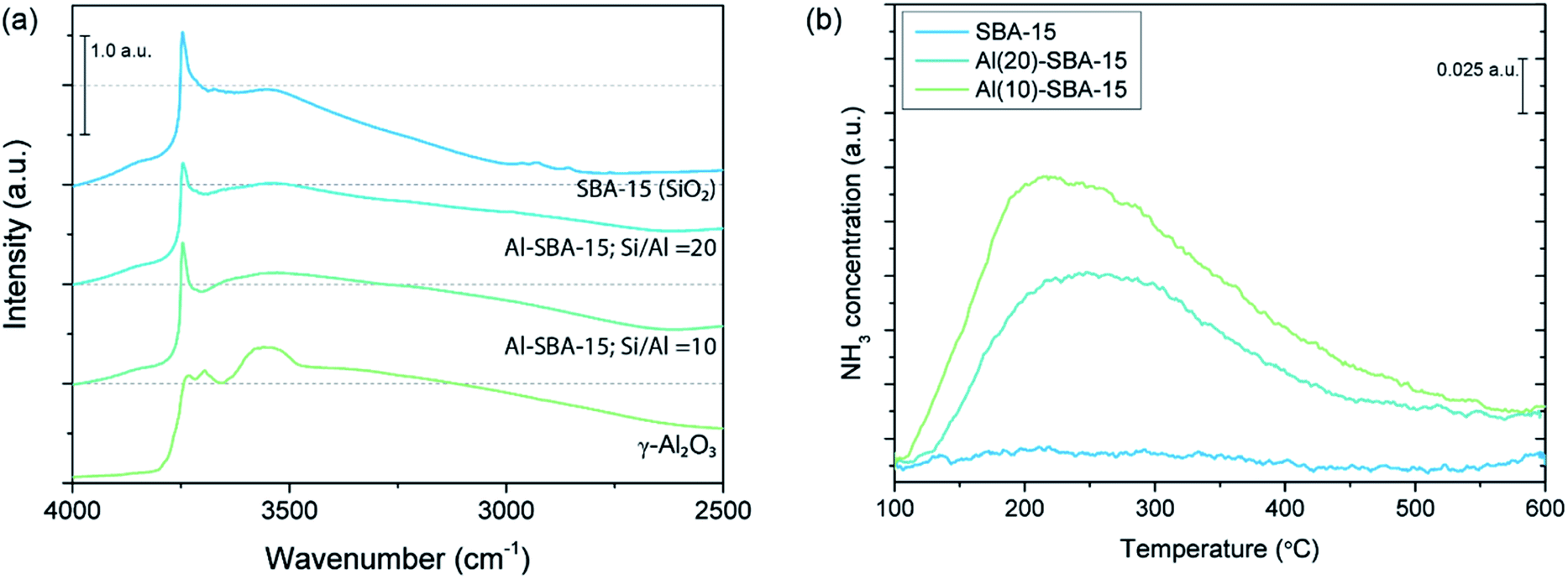 | ||
| Fig. 4 (a) DRIFTS spectra of SBA-15, Al-SBA-15 and γ-Al2O3, displaying the region related to hydroxyl stretching vibrations. (b) NH3-TPD of unmodified SBA-15 and aluminated SBA-15. | ||
Using NH3-TPD, the number of acid sites present in unmodified SBA-15 and aluminated SBA-15 that are sufficiently strong to interact with NH3 was determined. In Fig. 4b, the NH3-TPD measurements of unmodified SBA-15, Al(20)-SBA-15 and Al(10)-SBA-15 are depicted. It was found that the amount of acid sites increases from 18.5 μmol g−1 in the unmodified scaffold to 204.1 μmol g−1 in Al(20)-SBA-15 and 295.5 μmol g−1 in Al(10)-SBA-15. To compare, γ-Al2O3 contains 624.0 μmol g−1 acid sites. Therefore, both DRIFTS and NH3-TPD analysis confirm that the surface of SBA-15 was successfully modified through alumination. Moreover, the porosity of the scaffolds was analysed with N2 physisorption. The obtained information on porosity of the scaffolds is summarized in Table S2.† Compared to the unmodified SBA-15, surface alumination results in a minor decrease in pore volume from 0.99 to 0.92 cm3 g−1 for both aluminated scaffolds. Altogether, the prepared aluminated SBA-15 scaffolds are a useful model system with varying surface chemistry and without significant differences in pore size, pore volume or surface area.
The aluminated SBA-15 scaffolds were used to prepare nanoconfined LiBH4–LiNH2. In Fig. 5 the conductivities of the LiBH4–LiNH2/metal oxide nanocomposites prepared with SBA-15, Al(20)-SBA-15, Al(10)-SBA-15 are shown. The room temperature conductivity of the prepared nanocomposites was larger than for non-confined LiBH4–LiNH2. Interestingly, the nanocomposite conductivity increased slightly from 2.0 × 10⁻⁴ S cm−1 to 3.6 × 10⁻⁴ S cm−1 with increasing surface alumination. It is not likely that this difference is related to the minor difference in scaffold porosity. This observation therefore suggests that the difference in conductivity results from the change in the surface chemistry arising from alumination.
 | ||
| Fig. 5 Arrhenius plots of conductivity versus reciprocal temperature of LiBH4–LiNH2 nanoconfined in γ-Al2O3, SBA-15 and aluminated SBA-15. | ||
Further insight into the effect of surface alumination is provided by analysis of the activation energy for ionic transport. For LiBH4–LiNH2/SBA-15 nanocomposites an activation energy of 0.68 (±0.01) eV is found, which is similar to the values observed for the MCM-41-based nanocomposites. Surprisingly, the activation energy increases significantly in nanocomposites prepared with aluminated SBA-15 to 0.86 (±0.03) eV (Si/Al = 20) and 0.90 (±0.04) eV (Si/Al = 10). Here, a change in activation energy might be caused by the difference in surface chemistry through alumination, which influences the interactions between the scaffold surface and the nanoconfined metal hydride. This is another strong indication that the surface chemistry influences ion mobility in the nanocomposites.
The increase in conductivity with increasing surface alumination could be caused by two surface chemistry properties. Firstly, previous studies on LiBH4 nanoconfined in mesoporous SiO2 demonstrated that the ionic conductivity is strongly influenced by the density of the surface silanol groups. Specifically, a higher density of surface silanol groups is associated with a larger conductivity enhancement.43 Since alumina generally contains about 10 hydroxyl groups per nm2 while silica only contains 4 to 5.5 groups per nm2,70 it is expected that aluminated SBA-15 contains more surface hydroxyl groups than unmodified SBA-15, which could explain an increase in conductivity. Additionally, as illustrated with NH3-TPD, the chemical nature of surface hydroxyl groups in unmodified SBA-15 and aluminated SBA-15 varies significantly. While SiO2 (SBA-15) contains weakly acidic hydroxyl groups, aluminated SBA-15 contains surface groups with either acidic or basic character, similar to γ-Al2O3. The difference in chemical nature of the surface groups will likely alter the nature and strength of the interfacial interactions with nanoconfined LiBH4–LiNH2, thereby changing conductivity. With this in mind, it becomes clear that the surface chemistry of the scaffold can have a huge impact on the conductivity of LiBH4–LiNH2/metal oxide nanocomposites.
Surprisingly, the conductivity of the nanocomposite prepared with pure alumina (LiBH4–LiNH2/γ-Al2O3) was much lower than for the nanocomposites prepared with SBA-15 and Al-SBA-15. In fact, at room temperature the conductivity was almost 10 times lower than that of LiBH4–LiNH2/Al(10)-SBA-15 (6.7 × 10⁻⁵ S cm−1), despite the fact that the amount of surface acid sites present in γ-Al2O3 is significantly higher (624.0 μmol g−1 compared to 295.5 μmol g−1). It is important to realize that the physical properties, especially the porosity, of γ-Al2O3 and aluminated SBA-15 differ substantially. For instance, the pore volume is 0.92 cm3 g−1 for Al-SBA-15 and 0.48 cm3 g−1 for γ-Al2O3, while Al-SBA-15 contains small uniform pores (ø = 6.6 nm) and Al2O3 has a broad pore size distribution (ø = 6.3–11.1 nm) (Table S2†). Hence, the difference in conductivity cannot be solely ascribed to the difference in surface chemistry. Instead, it seems that other factors, especially the physical properties (surface area, pore structure and pore volume) of the scaffold, might play a crucial role in the enhancement of nanocomposite conductivity as well.
| T condensation SBA-15 | Pore volume (cm3 g−1) | BET surface area (m2 g−1) |
|---|---|---|
| 45 °C | 0.54 | 609.9 |
| 60 °C | 0.51 | 610.5 |
| 75 °C | 0.74 | 834.1 |
| 90 °C | 0.71 | 720.9 |
| 100 °C | 1.06 | 805.1 |
| 120 °C | 1.00 | 628.7 |
 | ||
| Fig. 6 Pore volume versus pore diameter as determined with BJH analysis of SBA-15 scaffolds synthesized with condensation temperatures varying from 45 °C to 120 °C. | ||
The SBA-15 scaffolds were used to prepare nanoconfined LiBH4-50% LiNH2, as well as nanoconfined LiBH4 for comparison. The conductivity of the resulting nanocomposites is displayed in Fig. 7a and b. It is evident that the conductivity of the LiBH4–LiNH2/SBA-15 nanocomposites differs significantly. Notably, at 30 °C the nanocomposites based on SBA-15 synthesized with Tc = 60 °C and Tc = 120 °C exhibit a difference of over three orders of magnitude in conductivity, from 3.6 × 10⁻⁷ S cm−1 to 5.1 × 10⁻⁴ S cm−1, respectively. In contrast, LiBH4/oxide nanocomposites prepared with these SBA-15 scaffolds display only a minor difference in conductivity, as the conductivity only differs by a factor of 4 when the nanocomposites are prepared with SBA-15 synthesized with Tc = 90 °C (6.9 × 10⁻⁶ S cm−1) and Tc = 120 °C (2.5 × 10⁻⁵ S cm−1).
 | ||
| Fig. 7 Arrhenius plots showing conductivity versus reciprocal temperature of (a) LiBH4–LiNH2/metal oxide nanocomposites and (b) LiBH4/metal oxide nanocomposites prepared with the synthesized SBA-15 scaffolds. (c) Correlation between nanocomposite conductivity and pore volume of the applied SBA-15 scaffold, including the linear fit (y = −9.5 + 5.9x) and 95% confidence interval. | ||
It is important to realize that pellet porosity (void fraction) can be different for the different nanocomposites and thereby influence the conductivity. However, differences in void fractions are not expected to play a dominant role here, because LiBH4–LiNH2/oxide and LiBH4/oxide nanocomposites are both soft materials that likely exhibit a similar pellet porosity when compressed with the same force (as in this study). Also, comparing the dependence of their conductivity to the scaffold pore volume illustrates that the void fraction is not the determinant factor for the increase in conductivity of LiBH4–LiNH2/oxide nanocomposites with increasing scaffold pore volume.
Interestingly, while a large difference in conductivity is observed for the LiBH4–LiNH2 nanoconfined in the different SBA-15 scaffolds, the activation energy for ion transport remains generally the same. For example, an activation energy of 0.75 (±0.03) eV and 0.72 (±0.02) eV are found for nanocomposites prepared with the scaffolds synthesized at 60 °C and 120 °C, respectively. This indicates that the intrinsic conduction mechanism is similar in all LiBH4–LiNH2/SBA-15 nanocomposites, and that it is instead the density of charge carriers that influences the conductivity.
Even though it is obvious that scaffold porosity influences the nanocomposite conductivity, it is not easy to pinpoint which physical property, e.g. pore volume, surface area or pore diameter, dictates the overall conductivity. Variation in the SBA-15 condensation temperature affects each structural parameter, hence a detailed analysis is performed in which the conductivity is separately correlated to pore diameter, surface area and pore volume (Fig. S7†). Surprisingly, no clear trend was established between the conductivity of the nanocomposites and either the pore diameter or the surface area of the SBA-15. In fact, a clear correlation was only observed with the pore volume of the scaffold (Fig. 7c). From a general linear fit (y = a + bx) on the log–linear scale, the relation log(σ) = −9.5 + 5.9Vpore is derived, showing a clear dependence of the conductivity to the scaffold pore volume. The main dependence of the conductivity on pore volume is unexpected, as in the previous section it was shown that interface interactions contribute to an enhance conductivity in nanoconfined anion-substituted metal hydrides.
The strong correlation between conductivity and pore volume strongly suggests that the conductivity enhancement in LiBH4–LiNH2/metal oxide nanocomposites is mostly a result of stabilization of a highly conductive HT phase at room temperature in the scaffold pores. Note that this is distinctly different for LiBH4/metal oxide nanocomposites, in which the conductivity enhancement is ascribed to the formation of a conductive interface layer. This is also in accord with the EIS results that indicate the absence of phase transitions over the temperature range between 25 °C and 50 °C. A large pore volume is indeed expected to be beneficial for conductivity enhancement by phase stabilization. As explained in the experimental section, each nanocomposite contains an amount of LiBH4–LiNH2 that is equal to 130% of the scaffold pore volume. Consequently, a higher pore volume results in a larger weight and volume fraction of the highly conducting phase (nanoconfined LiBH4–LiNH2) compared to the weight fraction of insulating SiO2 scaffold. For instance, the nanocomposite based on SBA-15 synthesized with Tc = 60 °C contains 36.4 wt% LiBH4–LiNH2 and 63.6 wt% SiO2, while the nanocomposite based on SBA-15 synthesized with Tc = 120 °C consists for 52.8 wt% of LiBH4–LiH2 and 47.2 wt% of SiO2. The higher weight fraction of phase stabilized LiBH4–LiNH2 compared to the fraction of insulating SiO2 leads to greater improvement in conductivity, hence, a high scaffold pore volume is beneficial for the nanocomposite conductivity.
This is in contrast to the case where the improved conductivity would be dictated by interface effects, as observed in nanoconfined LiBH4. In Fig. 7b and S8† it can be observed that the conductivity of LiBH4/oxide nanocomposites does not depend on the weight fraction of LiBH4, and correspondingly, the scaffold pore volume. The absence of this correlation is in line with previous studies indicating that not the stabilization of the HT hexagonal LiBH4 phase, but rather a reaction or interaction at the interface with the oxide is responsible for the high conductivity of nanoconfined LiBH4. Hence, a high surface area and/or a high density of the reactive surface groups would give rise to an increase in scaffold-metal hydride interface interactions. The correlations between conductivity and both pore diameter and BET surface area (Fig. S7†) illustrate that this is not the case for nanoconfined LiBH4–LiNH2.
It is clear that within the range of the pore sizes (5.1–8.3 nm) studied here, the nanocomposites conductivity is mainly influenced by the scaffold pore volume, which determines the amount of the electrolyte that is nanoconfined per gram of mesoporous metal oxide. However, note that although no correlation exists between the conductivity and pore diameter (Fig. S7†), a pore diameter considerably larger than 8.3 nm will surely have a profound impact on the nanocomposite conductivity. According to the Gibbs–Thomson relation, the depression of the phase transition temperature of a confined material is inversely proportional to the pore size of the scaffold. Hence, stabilization of the high temperature LiBH4–LiNH2 phase at room temperature will only occur in nanopores that are small enough to induce a sufficient decrease in the phase transition temperature. Therefore, we can conclude that when conductivity enhancement originates from conductive phase stabilization, scaffolds with high pore volume and small pores are beneficial, while for conductivity enhancement mainly driven by interface interactions, scaffolds with high surface area are essential.
Conclusions
The influence of scaffold properties on the conductivity of nanoconfined LiNH2-substituted LiBH4 was systematically investigated using metal oxides with different surface chemistry and physical properties. The study reveals that the chemical nature of the scaffold influences the LiBH4–LiNH2/metal oxide conductivity, as is expected. A conductivity improvement of a factor of two is achieved by changing the surface chemistry of SBA-15 through alumination. Surprisingly, the main factor contributing to an enhanced conductivity in LiBH4–LiNH2/metal oxide nanocomposites, is the pore volume of the scaffold. A difference of three orders of magnitude in conductivity (reaching 5 × 10⁻⁴ S cm−1 at 30 °C) is observed by varying the scaffold pore volume from 0.51 to 1.00 cm3 g−1.Our work demonstrates that the origin of the conductivity enhancement in anion-substituted complex hydride-based solid electrolytes is quite different from other nanoconfined complex hydrides, e.g. LiBH4. Specifically, the conductivity can be enhanced not only via the formation of a highly conductive interface layer, but also via the stabilization of a high temperature (highly conductive) phase at room temperature. Thus, it is clear that the conductivity of metal hydride-based nanocomposite ion conductors is closely linked to the properties of scaffold materials.
While the enhancement of electrolyte conductivity is the focus of this study, other electrolyte properties, such as electrochemical stability and interface stability with electrode materials, are also essential for application. This constitutes the next milestone for the LiBH4–LiNH2/oxide nanocomposites. However, the successful application of similar systems, i.e. LiBH4–LiI/Al2O3 and non-confined Li(BH4)1−x(NH2)x, demonstrates that metal hydride-based electrolytes are promising candidates for ASS batteries.
Conflicts of interest
There are no conflicts to declare.Acknowledgements
We greatly appreciate funding from the NWO materials for sustainability (739.017.009) grant, as well as the NWO ECHO (712.015.005) grant. Furthermore, we thank Silvia Zanoni for physisorption measurements, Jan Willem de Rijk and Dennie Wezendonk for their technical support, as well as Matt Peerlings and Oscar Brandt Corstius for the synthesis of nanoconfined LiNH2 and MCM-41, respectively.Notes and references
- B. Dunn, H. Kamath and J. M. Tarascon, Science, 2011, 334, 928–935 CrossRef CAS.
- D. Larcher and J. M. Tarascon, Nat. Chem., 2015, 7, 19–29 CrossRef CAS.
- D. L. McCollum, W. Zhou, C. Bertram, H. S. De Boer, V. Bosetti, S. Busch, J. Després, L. Drouet, J. Emmerling, M. Fay, O. Fricko, S. Fujimori, M. Gidden, M. Harmsen, D. Huppmann, G. Iyer, V. Krey, E. Kriegler, C. Nicolas, S. Pachauri, S. Parkinson, M. Poblete-Cazenave, P. Rafaj, N. Rao, J. Rozenberg, A. Schmitz, W. Schoepp, D. Van Vuuren and K. Riahi, Nat. Energy, 2018, 3, 589–599 CrossRef.
- J. B. Goodenough and K. S. Park, J. Am. Chem. Soc., 2013, 135, 1167–1176 CrossRef CAS.
- J. Janek and W. G. Zeier, Nat. Energy, 2016, 1, 1–4 Search PubMed.
- A. Manthiram, X. Yu and S. Wang, Nat. Rev. Mater., 2017, 2, 1–16 Search PubMed.
- K. Takada, J. Power Sources, 2018, 394, 74–85 CrossRef CAS.
- J. G. Kim, B. Son, S. Mukherjee, N. Schuppert, A. Bates, O. Kwon, M. J. Choi, H. Y. Chung and S. Park, J. Power Sources, 2015, 282, 299–322 CrossRef CAS.
- K. Takada, Acta Mater., 2013, 61, 759–770 CrossRef CAS.
- J. Li, C. Ma, M. Chi, C. Liang and N. J. Dudney, Adv. Energy Mater., 2015, 5, 1–6 Search PubMed.
- J. C. Bachman, S. Muy, A. Grimaud, H. H. Chang, N. Pour, S. F. Lux, O. Paschos, F. Maglia, S. Lupart, P. Lamp, L. Giordano and Y. Shao-Horn, Chem. Rev., 2016, 116, 140–162 CrossRef CAS.
- P. E. de Jongh, D. Blanchard, M. Matsuo, T. J. Udovic and S. Orimo, Appl. Phys. A Mater. Sci. Process., 2016, 122, 1–6 CrossRef CAS.
- R. Mohtadi and S. I. Orimo, Nat. Rev. Mater., 2016, 2, 1–16 Search PubMed.
- M. Matsuo, Y. Nakamori, S. I. Orimo, H. Maekawa and H. Takamura, Appl. Phys. Lett., 2007, 91, 2–5 Search PubMed.
- M. Matsuo and S. I. Orimo, Adv. Energy Mater., 2011, 1, 161–172 CrossRef CAS.
- A. Unemoto, M. Matsuo and S. I. Orimo, Adv. Funct. Mater., 2014, 24, 2267–2279 CrossRef CAS.
- M. Matsuo, H. Oguchi, T. Sato, H. Takamura, E. Tsuchida, T. Ikeshoji and S. I. Orimo, J. Alloys Compd., 2013, 580, S98–S101 CrossRef CAS.
- K. T. Møller, D. Sheppard, D. B. Ravnsbæk, C. E. Buckley, E. Akiba, H. W. Li and T. R. Jensen, Energies, 2017, 10, 1645 CrossRef.
- S. Kim, H. Oguchi, N. Toyama, T. Sato, S. Takagi, T. Otomo, D. Arunkumar, N. Kuwata, J. Kawamura and S. ichi Orimo, Nat. Commun., 2019, 10, 1–9 CrossRef.
- L. Duchêne, R. S. Kühnel, D. Rentsch, A. Remhof, H. Hagemann and C. Battaglia, Chem. Commun., 2017, 53, 4195–4198 RSC.
- R. Asakura, L. Duchêne, R. S. Kühnel, A. Remhof, H. Hagemann and C. Battaglia, ACS Appl. Energy Mater., 2019, 2, 6924–6930 CrossRef CAS.
- L. Duchêne, R. S. Kühnel, E. Stilp, E. Cuervo Reyes, A. Remhof, H. Hagemann and C. Battaglia, Energy Environ. Sci., 2017, 10, 2609–2615 RSC.
- H. Oguchi, M. Matsuo, J. S. Hummelshøj, T. Vegge, J. K. Nørskov, T. Sato, Y. Miura, H. Takamura, H. Maekawa and S. Orimo, Appl. Phys. Lett., 2009, 94, 2–5 CrossRef.
- H. Oguchi, M. Matsuo, T. Sato, H. Takamura, H. Maekawa, H. Kuwano and S. Orimo, J. Appl. Phys., 2010, 107, 105–108 CrossRef.
- L. H. Rude, E. Groppo, L. M. Arnbjerg, D. B. Ravnsbæk, R. A. Malmkjær, Y. Filinchuk, M. Baricco, F. Besenbacher and T. R. Jensen, J. Alloys Compd., 2011, 509, 8299–8305 CrossRef CAS.
- L. H. Rude, O. Zavorotynska, L. M. Arnbjerg, D. B. Ravnsbæk, R. A. Malmkjær, H. Grove, B. C. Hauback, M. Baricco, Y. Filinchuk, F. Besenbacher and T. R. Jensen, Int. J. Hydrogen Energy, 2011, 36, 15664–15672 CrossRef CAS.
- M. Matsuo, H. Takamura, H. Maekawa, H. W. Li and S. I. Orimo, Appl. Phys. Lett., 2009, 94, 2–5 CrossRef.
- R. Miyazaki, T. Karahashi, N. Kumatani, Y. Noda, M. Ando, H. Takamura, M. Matsuo, S. Orimo and H. Maekawa, Solid State Ionics, 2011, 192, 143–147 CrossRef CAS.
- Y. Yan, R. S. Kühnel, A. Remhof, L. Duchêne, E. C. Reyes, D. Rentsch, Z. Łodziana and C. Battaglia, Adv. Energy Mater., 2017, 7, 1–7 Search PubMed.
- H. Maekawa, M. Matsuo, H. Takamura, M. Ando, Y. Noda, T. Karahashi and S. I. Orimo, J. Am. Chem. Soc., 2009, 131, 894–895 CrossRef CAS.
- D. Sveinbjörnsson, J. S. G. Myrdal, D. Blanchard, J. J. Bentzen, T. Hirata, M. B. Mogensen, P. Norby, S. I. Orimo and T. Vegge, J. Phys. Chem. C, 2013, 117, 3249–3257 CrossRef.
- M. B. Ley, S. Boulineau, R. Janot, Y. Filinchuk and T. R. Jensen, J. Phys. Chem. C, 2012, 116, 21267–21276 CrossRef CAS.
- T. Mezaki, Y. Kuronuma, I. Oikawa, A. Kamegawa and H. Takamura, Inorg. Chem., 2016, 55, 10484–10489 CrossRef CAS.
- Z. Yao, S. Kim, K. Michel, Y. Zhang, M. Aykol and C. Wolverton, Phys. Rev. Mater., 2018, 2, 37–39 Search PubMed.
- D. Blanchard, A. Nale, D. Sveinbjörnsson, T. M. Eggenhuisen, M. H. W. Verkuijlen, S. Suwarno, T. Vegge, A. P. M. Kentgens and P. E. De Jongh, Adv. Funct. Mater., 2015, 25, 184–192 CrossRef CAS.
- S. Breuer, V. Pregartner, S. Lunghammer and H. M. R. Wilkening, J. Phys. Chem. C, 2019, 123, 5222–5230 CrossRef CAS.
- S. Das, P. Ngene, P. Norby, T. Vegge, P. E. de Jongh and D. Blanchard, J. Electrochem. Soc., 2016, 163, A2029–A2034 CrossRef CAS.
- M. H. W. Verkuijlen, P. Ngene, D. W. De Kort, C. Barré, A. Nale, E. R. H. Van Eck, P. J. M. Van Bentum, P. E. De Jongh and A. P. M. Kentgens, J. Phys. Chem. C, 2012, 116, 22169–22178 CrossRef CAS.
- N. Verdal, T. J. Udovic, J. J. Rush, X. Liu, E. H. Majzoub, J. J. Vajo and A. F. Gross, J. Phys. Chem. C, 2013, 117, 17983–17995 CrossRef CAS.
- Y. S. Choi, Y. S. Lee, D. J. Choi, K. H. Chae, K. H. Oh and Y. W. Cho, J. Phys. Chem. C, 2017, 121, 26209–26215 CrossRef.
- S. F. H. Lambregts, E. R. H. Van Eck, S. Suwarno, P. Ngene, P. E. De Jongh and A. P. M. Kentgens, J. Phys. Chem. C, 2019, 123, 25559–25569 CrossRef CAS.
- Y. S. Choi, Y. S. Lee, K. H. Oh and Y. W. Cho, Phys. Chem. Chem. Phys., 2016, 18, 22540–22547 RSC.
- P. Ngene, S. F. H. Lambregts, D. Blanchard, T. Vegge, M. Sharma, H. Hagemann and P. E. De Jongh, Phys. Chem. Chem. Phys., 2019, 21, 22456–22466 RSC.
- J. Lefevr, L. Cervini, J. M. Griffin and D. Blanchard, J. Phys. Chem. C, 2018, 122, 15264–15275 CrossRef CAS.
- P. E. De Jongh and T. M. Eggenhuisen, Adv. Mater., 2013, 25, 6672–6690 CrossRef CAS.
- A. Gutowska, L. Li, Y. Shin, C. M. Wang, X. S. Li, J. C. Linehan, R. S. Smith, B. D. Kay, B. Schmid, W. Shaw, M. Gutowski and T. Autrey, Angew. Chemie, 2005, 117, 3644–3648 CrossRef.
- D. T. Shane, R. L. Corey, C. McIntosh, L. H. Rayhel, R. C. Bowman, J. J. Vajo, A. F. Gross and M. S. Conradi, J. Phys. Chem. C, 2010, 114, 4008–4014 CrossRef CAS.
- P. Ngene, P. Adelhelm, A. M. Beale, K. P. De Jong and P. E. De Jongh, J. Phys. Chem. C, 2010, 114, 6163–6168 CrossRef CAS.
- A. Remhof, P. Mauron, A. Züttel, J. P. Embs, Z. Łodziana, A. J. Ramirez-Cuesta, P. Ngene and P. De Jongh, J. Phys. Chem. C, 2013, 117, 3789–3798 CrossRef CAS.
- P. N. Suwarno, A. Nale, T. M. Eggenhuisen, M. Oschatz, J. P. Embs, A. Remhof and P. E. De Jongh, J. Phys. Chem. C, 2017, 121, 4197–4205 CrossRef CAS.
- J. Maier, Prog. Solid State Chem., 1995, 23, 171–263 CrossRef CAS.
- C. C. Liang, J. Electrochem. Soc., 1973, 120, 1289 CrossRef CAS.
- R. Zettl, L. de Kort, M. Gombotz, H. M. R. Wilkening, P. E. de Jongh and P. Ngene, J. Phys. Chem. C, 2020, 124, 2806–2816 CrossRef CAS.
- R. Zettl, M. Gombotz, D. Clarkson, S. G. Greenbaum, P. Ngene, P. E. de Jongh and H. M. R. Wilkening, ACS Appl. Mater. Interfaces, 2020, 12, 38570–38583 CrossRef CAS.
- F. Lu, Y. Pang, M. Zhu, F. Han, J. Yang, F. Fang, D. Sun, S. Zheng and C. Wang, Adv. Funct. Mater., 2019, 29, 1–7 Search PubMed.
- C. F. Cheng, D. H. Park and J. Klinowski, J. Chem. Soc. Faraday. Trans., 1997, 93, 193–197 RSC.
- H. I. Lee, J. H. Kim, G. D. Stucky, Y. Shi, C. Pak and J. M. Kim, J. Mater. Chem., 2010, 20, 8483–8487 RSC.
- M. Baca, E. de la Rochefoucauld, E. Ambroise, J. M. Krafft, R. Hajjar, P. P. Man, X. Carrier and J. Blanchard, Microporous Mesoporous Mater., 2008, 110, 232–241 CrossRef CAS.
- S. Brunauer, P. H. Emmett and E. Teller, J. Am. Chem. Soc., 1938, 60, 309–319 CrossRef CAS.
- E. P. Barrett, L. G. Joyner and P. P. Halenda, J. Am. Chem. Soc., 1951, 73, 373–380 CrossRef CAS.
- T. Noritake, M. Aoki, S. Towata, A. Ninomiya, Y. Nakamori and S. Orimo, Appl. Phys. A Mater. Sci. Process., 2006, 83, 277–279 CrossRef CAS.
- G. P. Meisner, M. L. Scullin, M. P. Balogh, F. E. Pinkerton and M. S. Meyer, J. Phys. Chem. B, 2006, 110, 4186–4192 CrossRef CAS.
- Y. Yan, J. B. Grinderslev, Y. S. Lee, M. Jørgensen, Y. W. Cho, R. Černý and T. R. Jensen, Chem. Commun., 2020, 56, 3971–3974 RSC.
- V. D'Anna, A. Spyratou, M. Sharma and H. Hagemann, Spectrochim. Acta Mol. Biomol. Spectrosc., 2014, 128, 902–906 CrossRef.
- J. P. O. Bohger, R. R. Eßmann and H. Jacobs, J. Mol. Struct., 1995, 348, 325–328 CrossRef CAS.
- B. A. Morrow and A. J. McFarlan, J. Phys. Chem., 1992, 96, 1395–1400 CrossRef CAS.
- A. G. Merzhanov, V. V. Barzykin, A. S. Shteinberg and V. T. Gontkovskaya, Thermochim. Acta, 1977, 21, 301–332 CrossRef CAS.
- D. Zhao, J. Feng, Q. Huo, N. Melosh, G. H. Fredrickson, B. F. Chmelka and G. D. Stucky, Science, 1998, 279, 548–552 CrossRef CAS.
- D. Zhao, J. Sun, Q. Li and G. D. Stucky, Chem. Mater., 2000, 12, 275–279 CrossRef CAS.
- I. Chorkendorff and J. W. Niemantsverdriet, Concepts of Modern Catalysis and Kinetics, John Wiley & Sons, Weinheim, 2nd edn, 2003 Search PubMed.
Footnote |
| † Electronic supplementary information (ESI) available: Synthesis procedure of mesoporous oxides, weight- and molar percentage of all samples; additional XRD, DRIFTS and DSC results of all solid solutions and nanocomposites; nitrogen physisorption of mesoporous oxides; additional conductivity data, including correlations with pore structure. See DOI: 10.1039/d0ta07600g |
| This journal is © The Royal Society of Chemistry 2020 |