
 Open Access Article
 This Open Access Article is licensed under a Creative Commons Attribution-Non Commercial 3.0 Unported Licence
Reversible switching between positive and negative thermal expansion in a metal–organic framework DUT-49†
Bikash
Garai‡
a,
Volodymyr
Bon‡
 *a,
Anastasia
Efimova
b,
Martin
Gerlach
c,
Irena
Senkovska
a and
Stefan
Kaskel
*a
*a,
Anastasia
Efimova
b,
Martin
Gerlach
c,
Irena
Senkovska
a and
Stefan
Kaskel
*a
aDepartment of Inorganic Chemistry I, Technische Universität Dresden, Bergstraße 66, 01069, Dresden, Germany. E-mail: volodymyr.bon@tu-dresden.de; stefan.kaskel@tu-dresden.de
bDepartment of Inorganic Chemistry, Brandenburg University of Technology Cottbus-Senftenberg, Universitätsplatz 1, 01968, Senftenberg, Germany
cMacromolecular Crystallography Group, Helmholtz-Zentrum Berlin für Materialien und Energie, Albert-Einstein-Straße 15, 12489, Berlin, Germany
First published on 14th September 2020
Abstract
Three-dimensional architectures constructed via coordination of organic ligands to metal ions (broadly termed metal–organic frameworks, MOFs), are highly interesting for many demanding applications such as gas adsorption, molecular separation, heterogeneous catalysis, molecular sensing, etc. Being constructed from heterogeneous components, such framework solids show characteristic features from both the individual components and framework-specific features. One such interesting physicochemical property is thermal expansion, which arises from thermal vibration from the organic linker and metal ions. Herein, we show a very unique example of thermal responsiveness for the DUT-49 framework, a MOF well-known for its distinctive negative gas adsorption (NGA) properties. In the guest-free form, the framework shows another counter-intuitive phenomenon of negative thermal expansion (NTE), i.e. the lattice size increases with decrease of temperature. However, in the solvated state, it shows both NTE and positive thermal expansion (i.e. lattice size decreases with lowering of temperature, PTE) based on a specific temperature range. When the solvent exists in the liquid form inside the MOF pore, it retains the pristine NTE nature of the bare framework. But freezing of the solvent inside the pores induces the strain, which causes a structural transformation through in-plane bending of the linker and this squeezes the framework by ∼10% of the unit cell volume. This effect has been verified using 3 different solvents where the structural contraction occurs immediately at the freezing point of the individual solvent. Furthermore, studies on a series of DUT-49(M) frameworks with varying metals confirm the general applicability of this mechanism.
Introduction
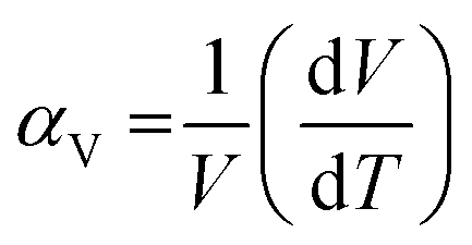
The stimuli responsiveness of porous metal–organic frameworks (MOFs) has led to important inventions in the field of switchable materials.1 These materials have many distinct benefits in terms of their application for gas storage, separation, chemical sensing, catalysis, etc.2–5 Being constructed from metal nodes and organic linkers, MOFs have multiple motifs that are capable of displaying structural flexibility. Such motifs include the overall framework6 or the individual constituents such as the metal cluster or secondary building unit (SBU),7 the organic linker, and hinges formed from deformable coordination bonds.8,9 The presence of multiple motifs provides a good combination for showing different flexible behaviours for various frameworks, based on the interaction with stimuli. Such a flexible behaviour of frameworks is best illustrated by breathing, swelling, subnetwork displacement, linker rotation, etc.10–14 Achieving a control on the structural transformation is thus the key step to control the respective properties of a framework.Introduction of thermal energy to a solid often stimulates its phase change by virtue of increased thermal vibration of the constituents. In the case of crystalline materials, this often leads to an increase in their physical dimensions, causing thermal expansion. From the structural viewpoint, this is related to the expansion of interatomic distances which results in an increase in the size of their crystallographic unit cell.15,16 The volumetric thermal expansion coefficient (αV) is generally reported in units of ppm K−1 (or MK−1) and is defined as per the following equation:17
For most common solids, a linear relationship is observed where the volume increases with the increase in temperature, which is defined as positive thermal expansion (PTE). However, a few classes of solids behave differently and reduce their volume upon increasing the temperature in the defined ranges. One of the archetypical examples of inorganic solids with negative thermal expansion (NTE) is zirconium tungstate, showing phonon-mediated collective translation, rotation and deformations of ZrO6 and WO4 polyhedra resulting in αV = −26 MK−1.18 Goodwin and co-workers discovered colossal NTE in the Prussian blue analogue Ag3[Co(CN)6], showing 14 fold greater NTE compared to that of Zr2W2O8.19 Simultaneously an exceptional NTE was predicted20,21 and experimentally observed22 in IRMOFs. Large-sized organic linkers sometimes undergo asymmetric thermal vibration which causes shrinkage of the unit cell with increase in temperature, i.e. NTE.17,22–25 NTE is a thermodynamic phenomenon and has been studied for a handful of MOF structures so far; however several aspects related to thermal transformation of MOFs are poorly understood. The largest NTE value of αV = −87.6 MK−1 was theoretically predicted for MOF-399 by Evans et al.17 However, it is not accessible experimentally because of the low mechanical stability of the framework. Interestingly, only a few substances show both PTE and NTE in the entire temperature range.26 The switching between PTE and NTE in the Prussian blue analogue YFe(CN)6 was recently reported by Chen and co-authors.27 However, there are no reports on the switching between PTE and NTE for highly porous MOFs. Herein, we present the first report for simultaneous positive and negative thermal expansion for the same MOF structure, under different conditions applied. A detailed study on the effect of guests for varying the flexibility of a DUT-49 framework is also described.
DUT-49(Cu) is a flexible MOF with unique characteristics. The deformation relies on linker buckling during gas adsorption. DUT-49(Cu) is constructed by the coordination of a tetracarboxylate linker [biphenyl bis(carbazole dicarboxylate), BBCDC] with a Cu based paddlewheel SBU.28 Topologically, this framework can be defined as metal–organic polyhedral (MOP) cores (formed from carbazoledicarboxylate/paddlewheel motif) interconnected through a biphenyl spacer (blue sphere in Fig. 1a). The biphenyl spacers generate two cavities (tetrahedral and octahedral) in addition to a MOP cavity which contributes to a major fraction of the overall porosity. The linker buckling during the adsorption ends in shrinkage of the pore volume by about 61%, forcing the adsorbed gas molecules to be expelled from the framework. This results in the unique negative gas adsorption (NGA) behaviour of the DUT-49 framework.29 Essentially, adsorption stress stimulates the shrinkage of the unit cell from 46.43 to 36.16 Å. However, several other parameters such as the adsorbate composition, adsorption temperature, crystallite size of the MOF, etc. strongly influence the framework flexibility.30–33 In this study, we explore the role of temperature in introducing flexibility to the DUT-49 framework by analyzing the framework dynamics in the presence of solvent molecules and with argon gas at atmospheric pressure. Studying the desolvated MOF reveals the purely thermally induced flexibility of the bare framework while the solvated MOF reflects the interaction with the solvent, through any change in the flexibility.
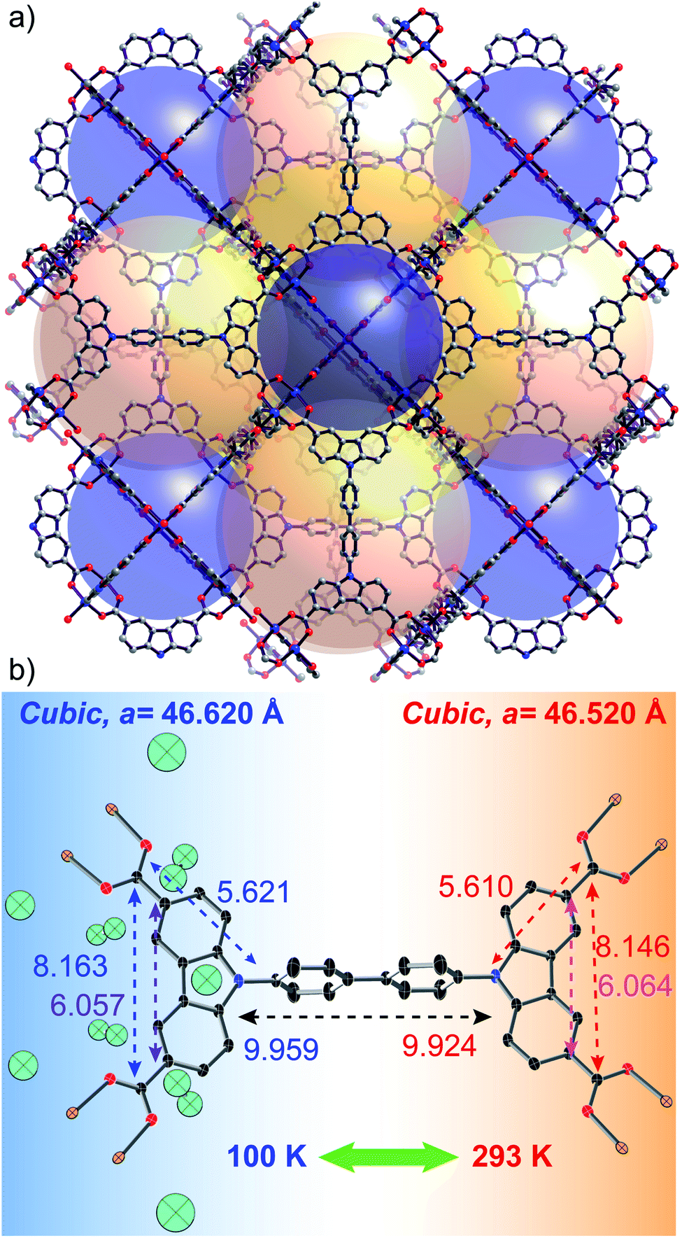 | ||
| Fig. 1 (a) Crystal structure of the DUT-49 MOF, showing the 3 types of pores with 3 coloured spheres. (b) Reversible structural change of the desolvated MOF unit (distances are in Å) under thermal conditions, initiated by the elongation of the linker at lower temperature. The cyan ellipsoids (50% probability level) represent crystallographically observed location of Ar atoms at 100 K. | ||
Results and discussion
From the family of DUT-49(M) [M = Mn, Fe, Co, Ni, Cu, Zn, and Cd], only Ni and Cu containing frameworks are capable of displaying adsorption-induced flexibility in combination with or without NGA phenomenon.34 For this reason, we selected DUT-49(Cu) for studying the thermally induced flexibility in both solvent-free and solvated states, through in situ synchrotron single crystal X-ray diffraction (SCD).Temperature dependent SCD studies of the desolvated DUT-49(Cu) framework
The thermal flexibility of the bare DUT-49 framework was studied on a single crystal of the DUT-49(Cu) MOF, desolvated using the supercritical CO2 approach. The crystal retains its single crystalline nature after the activation and shows a cubic unit cell with cell parameters of 46.520 Å at 293 K. Interestingly the axial positions of the paddlewheel SBUs are uncoordinated, which confirms the complete desolvation of the MOF. This is a very rare attempt to show the crystal structure of the supercritically desolvated mesoporous MOF, with non-coordinated axial positions of the paddlewheel SBUs. It is noteworthy that the desolvated crystal in an argon-filled capillary after cooling to 100 K, reveals the position of Ar atoms adsorbed on the open metal sites of the paddlewheels. This uniquely confirms the preferable argon adsorption sites of the framework through crystallographic evidence. Two argon adsorption sites are located close to the copper atoms of the paddlewheel showing Cu–Ar distances of 2.565 Å and 3.040 Å for inner and outer sites of the MOP (Fig. 1b). All other adsorption sites are located in the MOP window and confirm the earlier reported data on in situ neutron powder diffraction during methane adsorption.31 With the decrease of temperature to 100 K, the unit cell parameter is elongated to 46.620 Å with an increase of 651 Å3 in the unit cell volume. This accounts for a negative value of the thermal expansion coefficient (αV = −32.778 MK−1) indicating the counterintuitive thermal behaviour. Remarkably, the symmetry and space group of the unit cell remain unchanged (Fm![[3 with combining macron]](https://www.rsc.org/images/entities/char_0033_0304.gif) m) at both the temperatures. An increase in the cell volume at lower temperature (i.e. NTE) is also associated with a few structural changes of the MOF. For example, the M–Ocarboxylate distances increase from 1.933 to 1.941 Å and the spacer length between the carbazole moieties increases (Fig. 1b). Moreover, the thermal expansion/compression of the unit cell is observed to be reversible for more than 5 cycles. Structural analysis shows that this NTE phenomenon of DUT-49(Cu) originates from the linker dynamics, which undergoes elongation with lowering of temperature. The bond lengths inside the carbazole core remain almost constant during the thermal transition; however, the bonds with other fragments of the linker such as the biphenyl spacer and carboxylates get elongated because of the temperature lowering. This accounts for the overall elongation of the N–N distance from 9.924 to 9.959 Å and the C–C spacing between oppositely located carboxylates from 19.430 to 19.482 Å (Fig. 1b). It is noteworthy that a previous study has shown the elongation of bare biphenyl moieties with decrease in temperature, to avoid the steric hindrance between H atoms from the neighbouring phenyl rings.35 Thus it is very likely that a similar effect is operative for the desolvated framework DUT-49(Cu).
m) at both the temperatures. An increase in the cell volume at lower temperature (i.e. NTE) is also associated with a few structural changes of the MOF. For example, the M–Ocarboxylate distances increase from 1.933 to 1.941 Å and the spacer length between the carbazole moieties increases (Fig. 1b). Moreover, the thermal expansion/compression of the unit cell is observed to be reversible for more than 5 cycles. Structural analysis shows that this NTE phenomenon of DUT-49(Cu) originates from the linker dynamics, which undergoes elongation with lowering of temperature. The bond lengths inside the carbazole core remain almost constant during the thermal transition; however, the bonds with other fragments of the linker such as the biphenyl spacer and carboxylates get elongated because of the temperature lowering. This accounts for the overall elongation of the N–N distance from 9.924 to 9.959 Å and the C–C spacing between oppositely located carboxylates from 19.430 to 19.482 Å (Fig. 1b). It is noteworthy that a previous study has shown the elongation of bare biphenyl moieties with decrease in temperature, to avoid the steric hindrance between H atoms from the neighbouring phenyl rings.35 Thus it is very likely that a similar effect is operative for the desolvated framework DUT-49(Cu).
Switching between NTE and PTE in DMF solvated DUT-49(Cu) (DMF@DUT-49(Cu))
In comparison to solvent-free DUT-49(Cu), the N,N-dimethylformamide (DMF) solvated MOF shows a different trend with change in temperature. With the lowering of temperature from 298 K to 150 K, the unit cell parameters reduce significantly (from 46.620 to 45.660 Å) with a notable (∼6.4%) shrinkage of the unit cell volume. This reversal in the thermally induced flexibility trend can be explained by the solvent molecules present inside the pores of the MOF, which undergo phase transition during the cooling. Under ambient pressure freezing of DMF occurs at 212 K and it undergoes volume contraction upon the freezing. The significant amount of volume change prompted us to analyse all the structural changes occurring in combination with the lattice transformation. At first glance, a lowering of the lattice symmetry is observed during the freezing and the space group changes from Fmm to Pa. A similar study on DMF-loaded ultramicroporous Mn-based coordination polymers was reported by Zhang and co-workers.36 In temperature dependent SCD studies, the authors observed the changes in the ligand conformation close to the freezing point of DMF; however, PTE was registered in the whole temperature interval. The same authors observed colossal linear PTE and NTE in a Cd-based MOF with bcu topology; however, the volumetric expansion of the crystal was still positive with the increasing temperature.37 A deeper investigation into the outcomes from the in situ experiment shows two discrete stages for temperature dependence of the unit cell change. In the initial stage of the cooling (up to 200 K), a gradual increase in the lattice parameters is observed (Fig. 2b). This evidences a NTE phenomenon of the MOF in its solvated state, which shows very high values of αV (in the range of −40 to −70 MK−1). Surprisingly, a lattice squeezing occurred with a very fast rate beyond this temperature (αV = 435 MK−1). The NTE originates from the expansion of the linker and is similar to that already observed for the desolvated MOF. But, a sudden transition at 200 K appears, which reverses the thermal expansion trend. For the understanding of the mechanism of NTE and PTE in DMF filled DUT-49(M) in the temperature range of 293–150 K, the discussion in the following sections is divided into two separate parts, flexibility of the linker and flexibility of the paddlewheel SBU.
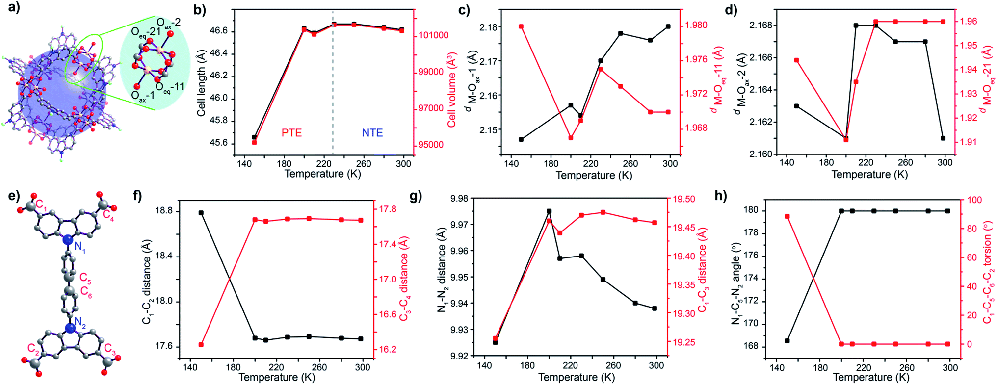 | ||
| Fig. 2 (a) Representative MOP unit and magnified SBU showing 2 different environments faced by the linker; (b) change in the cell length and volume of DMF solvated DUT-49(Cu) at different temperatures; evolution of axial and equatorial M–O bond lengths with temperature for (c) bonds facing the MOP core and (d) bonds facing the mesopore; (e) Structure of the linker and labeling of the conformation defining atoms that undergo thermal change measured through different parameters (f–h). | ||
The paddlewheel SBU is comprised of two metal centres connected by four carboxylic groups through their equatorial sites, and the axial sites are coordinated by solvent molecules. Thus, the variance in the distances between the metal centres and coordinating O atoms, along with M–O–M angles can clearly describe, if any flexibility is present at all. Therefore, we have monitored the change in their bond length and other parameters throughout the transformation by synchrotron single crystal X-ray diffraction on the same single crystal, measured in the same orientation at variable temperatures. At first, the M–O–M angle is measured at each carboxylate O with respect to the 2 metal centres of the paddlewheel SBU, as a measure of the stiffness of the paddlewheel SBU. Interestingly, the M–O–M angles of the SBU remain almost constant throughout the transformation (Table S8, ESI†). However, all of the eight M–O bonds do not face the same chemical environment; one half of the paddlewheel SBUs (four carboxylate O and one axial O atom) is pointed towards the MOP core of the framework while the remaining half faces the mesopores. This creates two different sets of coordinated O atoms, which are marked as Oax–1/2 and Oeq–11/21 (Fig. 2a). For the case of MOP facing O atoms, the M–O bond length for the axial O atom (M–Oax–1) starts dropping from 250 K and attains a minimum value at 200 K before increasing again. An identical trend is observed for the case of M–Ocarboxylate bond distances (M–Oeq–11) (Fig. 2c). The sharp minimum at 200 K suggests a sudden change in the expansion mechanism at this temperature. For the case of the other set of O atoms which face the mesopore, the axial O atom (M–Oax–2) does not show a regular trend; however the M–Ocarboxylate distance (M–Oeq–21) again shows a minimum at 200 K (Fig. 2d). This indicates that solvent molecules from the microporous MOP core interact more efficiently with the framework.
For describing the flexibility of the linker, we choose a few key atoms in its structural backbone (Fig. 2e). These atoms are chosen to describe any change in the length, aperture and torsion of the linker during the structural transformation. Thus, C1–C2 and C3–C4 distances describe the lateral size of the linker and during the cooling step they show an almost steady state until 200 K temperature. However, a drastic change in their distance is observed on further cooling beyond this point. Interestingly, when the lateral distance for one side of the linker (C1–C2) increases during the cooling step, the same for the other side of the linker (C3–C4 distance) decreases (Fig. 2f). This indicates an in-plane bending of the linker where C1 and C2 atoms approach closer to each other. The aperture of the linker monitored through the C1–C3 distance showed an immediate drop on cooling beyond 200 K temperature, supporting the in-plane bending of the linker. Monitoring of the N1–N2 distance again showed sharp shrinkage below 200 K temperature (Fig. 2g), indicating that the biphenyl moiety is the key fragment that undergoes deformation during the structural transition through in-plane bending. Moreover, the bending causes a decrease in the N1–C5–N2 angle from the linear 180° to 166°, along with a significant increase in the C1–C5–C6–C2 torsion angle from 0° to 80° (Fig. 2h). All these observations certainly confirm the in-plane bending of the linker, starting at 200 K. This linker buckling through deformation of the biphenyl spacer is somewhat similar to that observed during the NGA transition.
Consequently, in situ monitoring of the structural transformation clarifies the thermal flexibility of the DMF solvated DUT-49(Cu) framework through SBU and linker geometry deformation. The same crystal of the solvated MOF shows both positive and negative thermal expansion in the temperature range of 298–150 K. It is noteworthy that DMF, used as a guest in this study, has a freezing point of 212 K at 1 bar in bulk; however, it is known that fluids in the confined space e.g. MOF pores show a reduced freezing point. Since DMF belongs to fluids, which show contraction upon phase transition from the liquid to solid state, this indicates that at 200 K, DMF molecules inside the MOF pore get frozen and this volume change upon freezing triggers the lattice contraction and associated structural transformation of the DUT-49 framework. Although above 200 K, the framework behaves independently (similar to that of the desolvated MOF) and shows NTE phenomenon due to expansion of the linker. Therefore, it can be concluded that DMF in its liquid form does not significantly influence NTE behaviour, and it may consequently be declared as an intrinsic property of the framework DUT-49(Cu). At temperatures below 200 K, solidification of DMF molecules inside MOF pores triggers a structural transformation through in-plane bending of the linker (Fig. 3). In general, the phase transition is very similar to that observed upon desorption of methane from the open pore form of DUT-49(Cu) at 111 K, where slightly contracted op phases are observed. This structural transformation affects the overall lattice transformation with change in the lattice symmetry moreover reversing the trend of the thermal expansion coefficient. This hypothesis is further validated with low temperature differential scanning calorimetry (DSC) studies.
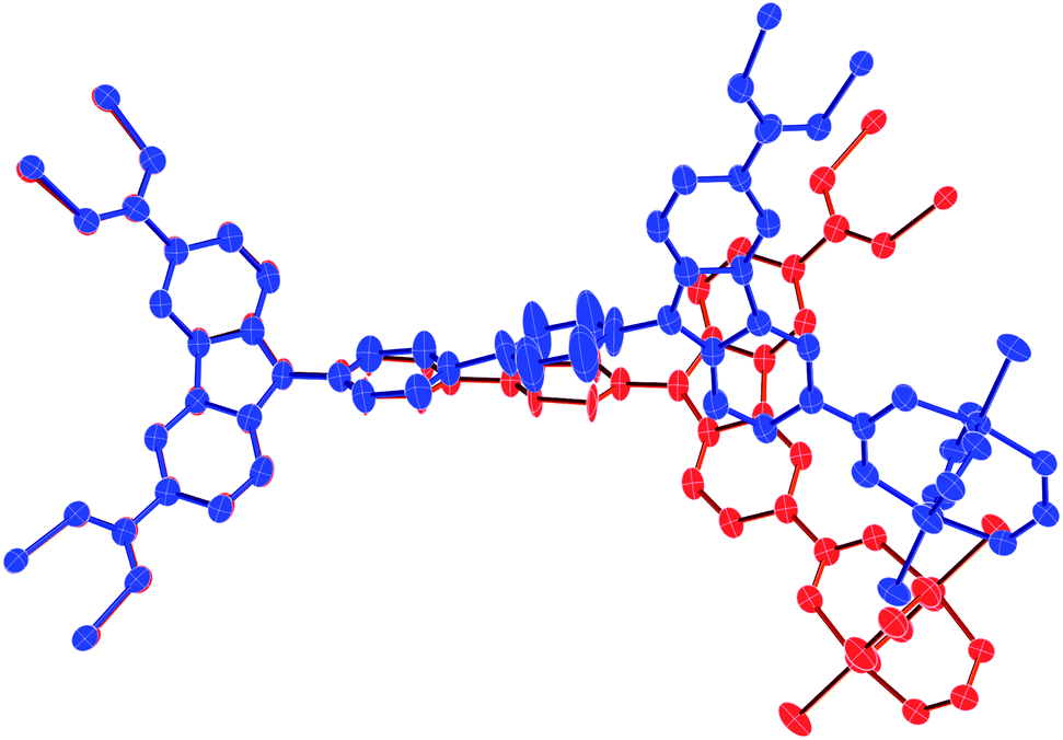 | ||
| Fig. 3 In-plane bending of the linker during solvent induced structural transformation from the planar conformation of the biphenyl spacer (red colour) at 298 K to a bent conformation (blue colour) at 150 K (hydrogen atoms are omitted for clarity). | ||
DSC studies on DMF@DUT-49(Cu)
DMF@DUT-49(Cu) and liquid DMF (as a reference sample) were cooled from ambient temperature down to 178 K. No crystallization effect for either DMF or DMF@DUT-49(Cu) could be detected during cooling. The changes in the cooling rate or the final temperature even down to 113 K did not affect the solidification behaviour and DMF remained under-cooled. In the next experiment, after reaching 178 K, the sample was equilibrated at 178 K for 30 min and after this it was heated up to 298 K. Obviously, the freezing of DMF takes place during the equilibration, as the DSC heating curve shows an endothermal effect at 210 K. The effect corresponds to the melting of DMF with an enthalpy of fusion (ΔHfus) of 102 Jg−1.In the subsequent experiment, the samples were placed in pre-cooled measuring cell at about 238 K (applying the thermal stress) and cooled down to 178 K. In this case the crystallization occurs and one exothermic peak at 183 K on the cooling curve and one endothermic peak at 210 K on the heating DSC curve were detected (Fig. 4), which correspond to crystallization and to melting, respectively. At temperatures above 230 K there are no further thermal effects and therefore the DSC curves are presented only up to this temperature. The melting enthalpy of the thermally stressed DMF sample is 111 Jg−1, which is 9 Jg−1 higher than that obtained in the previous experiment (102 Jg−1), confirming partial crystallization of the former one during equilibration at 178 K (Table 1). The DSC curve of thermally stressed DMF@DUT-49(Cu) is similar to the DSC curve of the thermally stressed reference DMF sample, and the melting of DMF in DMF@DUT-49(Cu) takes place at the same temperature (Tfus = 209 K). The structural transformation of DUT-49(Cu) during the cooling proceeds, obviously, simultaneously with the crystallization of DMF in the pores.
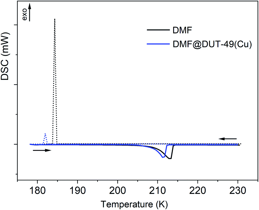 | ||
| Fig. 4 DSC heating and cooling curves for DMF (black) and DMF@DUT-49(Cu) (blue). | ||
| DMF | DMF@DUT-49(Cu) | |
|---|---|---|
| T cr, K | 183 ± 2 | 182 ± 2 |
| ΔHcr, Jg−1 | 101 ± 3 | 71 ± 1 |
| T fus, K | 210 ± 1 | 209 ± 1 |
| ΔHfus, Jg−1 | 111 ± 2 | 84 ± 1 |
The mass fraction of DMF in the DMF@DUT-49(Cu) sample amounts to 73.3%. So, according to estimations, the enthalpy of crystallization (ΔHcr) of DMF enclosed in the DUT-49(Cu) pores, which amounts to 97 Jg−1 is close to the enthalpy of crystallization of bulk DMF (101 Jg−1). Obviously, the enthalpy of the framework's structural transition is significantly smaller in comparison to the crystallization enthalpy of DMF and cannot be exactly determined in this experiment due to the measurement uncertainties.
Role of guest molecules in PTE/NTE switching
Further to test the role of solvent nature in triggering the structural transformation, different solvents (ethanol, N-methylpyrrolidone (NMP) and DMF) were introduced into the DUT-49(Cu) framework and subjected to similar monitoring by in situ single crystal X-ray diffraction. In all the cases, the solvated MOFs show NTE behaviour until the freezing point of the solvent, followed by PTE transition in the reverse order. DUT-49(Cu) containing EtOH shows initial NTE behaviour up to 180 K (Fig. 5a) with a value of αV ranging up to −68.77 MK−1. Upon further cooling beyond this point the trend is reversed to PTE with a volumetric coefficient of up to 258.53 MK−1. Detailed analysis of the paddlewheel geometry indicates that the M–Ocarboxylate (M–Oeq–11) bond shows a minimum length at 150 K, indicating the highest interaction at this temperature (Fig. 5b). However, it is noteworthy that no regular trend was observed for the mesopore facing O atoms (Fig. 5c). In contrast, the linker showed a clear sign of structural transition at 150 K; where the lateral dimensions (C1–C2 and C3–C4 distances) in the ligand change abruptly at the point (Fig. 5d). The biphenyl spacer length and the diagonal aspect of the linker change in a very irregular manner throughout the transformation; this makes it difficult to achieve any conclusive outcome (Fig. 5e). But the linker deformation through in-plane bending is prominent from the N1–C5–N2 angle and C1–C5–C6–C2 torsion angle analysis (Fig. 5f). Both of them showed a clear sign for structural deformation of the linker through in-plane bending, starting at 150 K. Also in this case the transition temperature is slightly lower than the freezing point of pure ethanol (159 K) at STP. This further showed that freezing of the solvent molecules inside the MOF pore is able to induce structural transition in the DUT-49 framework.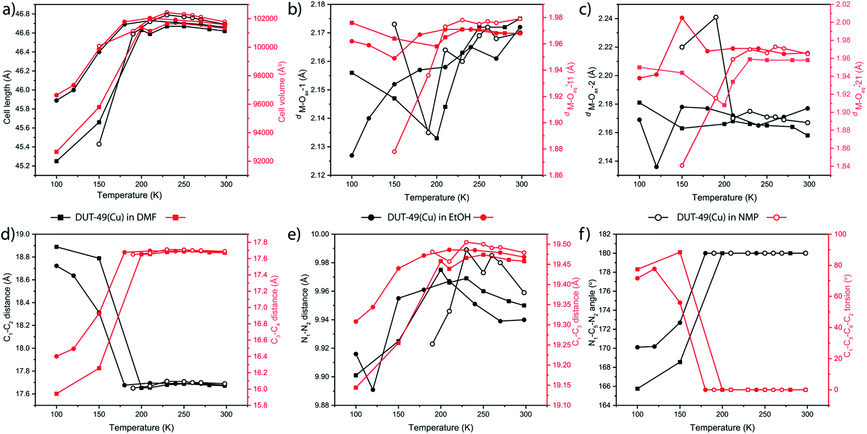 | ||
| Fig. 5 Comparison for thermal change in the (a) unit cell length and volume, (b, and c) M–Oax and M–Oeq bond lengths in the Cu-paddlewheel (labelling Fig. 2a), and (d, e, and f) linker conformation defining parameters (labelling Fig. 2e) of DUT-49(Cu) in the presence of different solvents. | ||
NMP on the other hand causes the highest NTE/PTE switching temperature, because of its higher freezing point. The lattice starts shrinking at 230 K. While cooling until this point, the NTE behaviour remains prominent (Fig. 5a). The transition temperature for this case is also closely related to the freezing point of NMP at ambient pressure. Considering the SBU flexibility analysis, it can be seen that both the M–Ocarboxylate bonds (M–Oeq–11 and M–Oeq–21) show shrinkage at 230 K (Fig. 4b and c). Although the linker configuration analysis at lower temperature was not successful, they show a similar trend (Fig. 5d–f) in the temperature range above the freezing point of NMP (249 K). This along with PTE behaviour indicates an identical structural transition from Fmm to Pa space groups at 230 K. In this case, the volumetric expansion coefficient values vary between −118.14 and 114.15 MK−1 showing the switching between NTE and PTE during the sequential cooling of the same single crystal.
This establishes that for each of the 3 tested solvent systems, their liquid phase does not affect the thermal properties of the DUT-49(Cu) framework, maintaining the NTE behaviour as observed for the desolvated framework. But, during the solidification of each of the 3 solvents at their individual freezing points, they undergo a phase transition. This phase transition of the solvent induces a constrained system and this causes a structural strain which ends with in-plane bending of the linker. It is likely that as the volume of the solvent reduces with the lowering of temperature, the freezing fluid constricts the neighbouring pore walls. This stress buckles the organic linker of the MOF to result in the in-plane bending of the linker. And during the heating stage the reverse process happens, where the melting solvent releases the strained system to its relaxed state with a linear conformation of the linker.
Role of metal ions in PTE/NTE switching
To verify the scope for generalization of the hypothesis, we performed the structural analysis at different temperatures with other MOFs of the DUT-49(M) family using in situ single crystal X-ray diffraction. Through a similar approach, single crystals for each of NMP solvated DUT-49(M) [M = Mn, Fe, Co, Ni, Zn, and Cd] MOFs were subjected to a temperature gradient between 296 K and 100 K. By decreasing the temperature from 296 K to 100 K, the unit cell symmetry for all the MOFs is reduced; which is reflected in the space group change from Fmm to Pa. Reduction in the symmetry is an indication for the linker deformation as discussed earlier, which is further confirmed by single crystal X-ray diffraction studies. In summary, all of the MOFs show shrinkage in the unit cell length and volume, with decreasing temperature (Fig. 6). On decreasing the temperature from 298 K to 100 K, their lattice parameters shrink significantly (∼10% of the initial cell volume), and recover reversibly with increasing temperature. This positive thermal expansion for the whole family of DUT-49(M) thus confirms the general applicability of the solvent induced stress hypothesis for bringing out structural deformation in the framework.
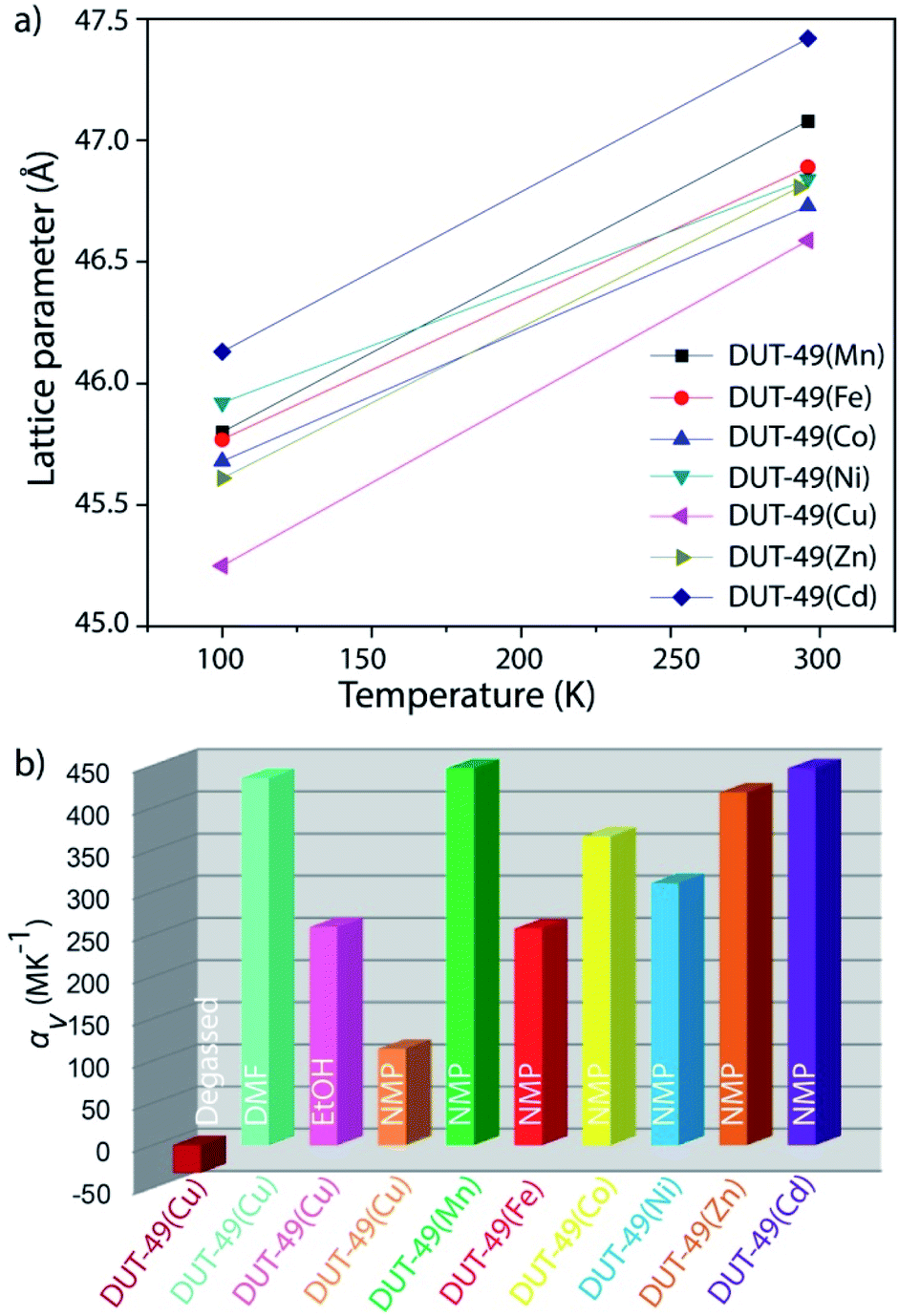 | ||
| Fig. 6 (a) Thermal expansion of NMP solvated DUT-49(M) MOFs showing a decrease in the unit cell size with decrease in the temperature; (b) volumetric thermal expansion coefficients of DUT-49(M) MOFs showing their overall PTE/NTE properties. | ||
Experimental
Synthesis of the materials
The organic linker (H4BBCDC) was synthesized and characterized using the same procedure as described in a previous report.34 A suitably sized single crystal of the MOF was obtained through post-synthetic metal exchange, starting from DUT-49(Co). DUT-49(Co) was synthesized from a direct solvothermal reaction of the H4BBCDC linker and Co(NO3)2·6H2O in NMP, as block shaped crystals. The crystals were then washed with fresh NMP to remove the unreacted starting materials and any other impurities. These fresh crystals were then subjected to metal exchange from the NMP solvent as per a previously reported pathway, to synthesize single crystals of DUT-49(M) [M = Mn, Fe, Ni, Cu, Zn, and Cd] MOFs. These newly obtained MOFs were then washed with fresh NMP until free from any residual metal ion and stored in fresh NMP. For solvent exchanged MOFs, the NMP soaked MOF crystals were dipped into the respective solvent and then the supernatant liquid was exchanged with a fresh solvent 6 times over a period of 24 h. These crystals were then stored in the same solvent and directly used for diffraction measurement experiments. The desolvated crystal of DUT-49(Cu) was prepared through supercritical CO2 treatment of an acetone exchanged crystal, using a Jumbo Critical Point Dryer 13200J AB (SPI Supplies). In this process, MOF crystals from dry acetone were taken in a sintered crucible with an aliquot of the solvent and then placed inside the dryer. Acetone was then exchanged with ultra-pure (99.995%) liquid carbon dioxide at 17 °C 10 times over a period of 5 days. The temperature and pressure inside the drying compartment were then raised above the critical point of carbon dioxide and the samples were left in this supercritical fluid for around 15 min. The pressure was then reduced through slow release of the fluid over 3 h. The chamber was then flushed with Ar for 15 min and then immediately transferred into an Ar-filled glove box.Single crystal X-ray diffraction
A single crystal of desolvated DUT-49(Cu) was prepared inside the glove box, in a sealed glass capillary (0.5 mm diameter) with an argon atmosphere. Single crystals of DMF@DUT-49(Cu), NMP@DUT-49(Cu) and EtOH@DUT-49(Cu) were prepared in glass capillaries with a small amount of the corresponding solvent and further sealed using wax. NMP@DUT-49(M) crystals (M = Mn, Fe, Co, Ni, Zn and Cd) were prepared in glass capillaries using the same procedure. The datasets were collected at the BESSY MX BL14.3 beamline of Helmholtz-Zentrum Berlin für Materialien und Energie.38 Monochromatic X-ray radiation with a wavelength of λ = 0.089499 nm (E = 13.85 keV) was used in the experiments. The crystal symmetry and scan range were determined in each particular case using the iMosflm program.39,40 The φ-scans with an oscillation range of 1° were used for data collection. For each dataset, 60 images were collected to reach the maximal completeness. Datasets on NMP@DUT-49(M) crystals were collected at 293 K and 100 K using the same single crystal orientation and angular oscillation range. The crystals were shock-frozen by introducing a nitrogen cryostream nozzle. Datasets on DMF@DUT-49(Cu), NMP@DUT-49(Cu) and EtOH@DUT-49(Cu) were collected at multiple temperatures ranging from 293 K to 100 K. In this case, corresponding temperature increments were introduced to cool down the crystals. The datasets were processed in an automatic regime using XDSAPP 2.0 software.41 Crystal structures were solved by direct methods and refined with full matrix least-squares on F2 using the SHELX-2018/3 program package.42,43 All non-hydrogen atoms were refined in anisotropic approximation. Hydrogen atoms were refined in geometrically calculated positions using the “riding model” with Uiso(H) = 1.2Uiso(C). The large pores, high crystal symmetry and room temperature data collection led to disorder of solvent molecules within the pores of the frameworks. Experimental data on single crystal X-ray experiments are summarized in tables S1–S7 (ESI).†Differential scanning calorimetry
The differential scanning calorimetry (DSC) experiments were carried out using a DSC 204 F1 Phoenix (NETZSCH) device and a DSC 1/700 (Mettler Toledo) device in the temperature range from 113 up to 200 K and from 178 up to 298 K, respectively. Both devices were regularly calibrated with an aid of reference substances. The characteristic temperatures derived from the DSC curves were extrapolated onset temperatures.Both DMF@DUT-49(Cu) and reference liquid DMF samples were prepared in sealed standard aluminium crucibles (40 μL) and measured at a cooling rate of 1 K min−1 and a heating rate of 2 K min−1 at a dry nitrogen flow rate of 20 mL min−1.
Conclusions
In summary, we have shown the first example of a transition from positive to negative thermal expansion for a highly porous MOF. By analysing the structures of DUT-49 solved from temperature dependent synchrotron single crystal X-ray diffraction data, we have pinpointed the reason behind the anomalous thermal behaviour of the framework. The framework of DUT-49(Cu) in the desolvated state shows NTE behaviour over the temperature range of 296–100 K, because of the elongation of the linker at lower temperatures. But the situation changes when the solvent is present inside the pores of the MOF, as has been verified using 3 different solvents, namely DMF, EtOH and NMP. A reduction in the freezing point of the solvent confined in the pores was observed. Moreover, the solvent molecules barely impact the thermal flexibility of the framework. This leads to identical NTE characteristics of DUT-49(Cu) above the freezing temperature of the individual solvent. However, the situation is inverted below freezing temperature where the compound shows positive thermal expansion features. This reversal is achieved because of the in-plane bending of the linker, which is stimulated by the freezing of the solvent inside MOF pores, as illustrated by DSC measurements of the melting and freezing. This in-plane bending leads to linker deformation along its biphenyl spacer and causes ∼10% reduction in the unit cell volume for the family of DUT-49(M) [M = Mn, Fe, Co, Ni, Cu, Zn, and Cd] MOFs.Conflicts of interest
There are no conflicts to declare.Acknowledgements
This project has received funding from the European Research Council (ERC) under the European Union's Horizon 2020 research and innovation programme (grant agreement No. 742743). The authors thank Helmholtz-Zentrum Berlin für Materialien und Energie (HZB) for the allocation of the synchrotron radiation beamtime at MX BL14.3 beamline and travel grants.Notes and references
- A. Schneemann, V. Bon, I. Schwedler, I. Senkovska, S. Kaskel and R. A. Fischer, Chem. Soc. Rev., 2014, 43, 6062–6096 RSC.
- J. A. Mason, J. Oktawiec, M. K. Taylor, M. R. Hudson, J. Rodriguez, J. E. Bachman, M. I. Gonzalez, A. Cervellino, A. Guagliardi, C. M. Brown, P. L. Llewellyn, N. Masciocchi and J. R. Long, Nature, 2015, 527, 357–361 CrossRef CAS.
- S. Xiong, Q. Liu, Q. Wang, W. Li, Y. Tang, X. Wang, S. Hu and B. Chen, J. Mater. Chem. A, 2015, 3, 10747–10752 RSC.
- X.-L. Lv, L.-H. Xie, B. Wang, M. Zhao, Y. Cui and J.-R. Li, J. Mater. Chem. C, 2018, 6, 10628–10639 RSC.
- R. K. Das, A. Aijaz, M. K. Sharma, P. Lama and P. K. Bharadwaj, Chem. – Eur. J., 2012, 18, 6866–6872 CrossRef CAS.
- N. Klein, C. Herzog, M. Sabo, I. Senkovska, J. Getzschmann, S. Paasch, M. R. Lohe, E. Brunner and S. Kaskel, Phys. Chem. Chem. Phys., 2010, 12, 11778–11784 RSC.
- C. Serre, F. Millange, C. Thouvenot, M. Noguès, G. Marsolier, D. Louër and G. Férey, J. Am. Chem. Soc., 2002, 124, 13519–13526 CrossRef CAS.
- R. Lyndon, K. Konstas, B. P. Ladewig, P. D. Southon, P. C. J. Kepert and M. R. Hill, Angew. Chem., Int. Ed., 2013, 52, 3695–3698 CrossRef CAS.
- S. Henke, A. Schneemann, A. Wütscher and R. A. Fischer, J. Am. Chem. Soc., 2012, 134, 9464–9474 CrossRef CAS.
- T. Loiseau, C. Serre, C. Huguenard, G. Fink, F. Taulelle, M. Henry, T. Bataille and G. Férey, Chem. – Eur. J., 2004, 10, 1373–1382 CrossRef CAS.
- C. Mellot-Draznieks, C. Serre, S. Surblé, N. Audebrand and G. Férey, J. Am. Chem. Soc., 2005, 127, 16273–16278 CrossRef CAS.
- F. Coudert, ChemPhysChem, 2017, 18, 2732–2738 CrossRef CAS.
- T. K. Maji, R. Matsuda and S. Kitagawa, Nat. Mater., 2007, 6, 142–148 CrossRef CAS.
- B. Chen, C. Liang, J. Yang, D. S. Contreras, Y. L. Clancy, E. B. Lobkovsky, O. M. Yaghi and S. Dai, Angew. Chem., Int. Ed., 2006, 45, 1390–1393 CrossRef CAS.
- D. Psimadas, P. Georgoulias, V. Valotassiou and G. Loudos, J. Pharm. Sci., 2012, 101, 2271–2280 CrossRef CAS.
- E. Vandersluis, D. Sediako, P. Emadi, C. Ravindran, A. Elsayed and G. Byczynski, J. Appl. Crystallogr., 2018, 51, 1141–1150 CrossRef CAS.
- J. D. Evans, J. P. Dürholt, S. Kaskel and R. Schmid, J. Mater. Chem. A, 2019, 7, 24019–24026 RSC.
- T. A. Mary, J. S. O. Evans, T. Vogt and A. W. Sleight, Science, 1996, 272, 90–92 CrossRef CAS.
- A. L. Goodwin, M. Calleja, M. J. Conterio, M. T. Dove, J. S. O. Evans, D. A. Keen, L. Peters and M. G. Tucker, Science, 2008, 319, 794–797 CrossRef CAS.
- D. Dubbeldam, K. S. Walton, D. E. Ellis and R. Q. Snurr, Angew. Chem., Int. Ed., 2007, 46, 4496–4499 CrossRef CAS.
- W. Zhou, H. Wu, T. Yildirim, J. R. Simpson and A. R. H. Walker, Phys. Rev. B, 2008, 78, 54114 CrossRef.
- N. Lock, Y. Wu, M. Christensen, L. J. Cameron, V. K. Peterson, A. J. Bridgeman, C. J. Kepert and B. B. Iversen, J. Phys. Chem. C, 2010, 114, 16181–16186 CrossRef CAS.
- N. C. Burtch, S. J. Baxter, J. Heinen, A. Bird, A. Schneemann, D. Dubbeldam and A. P. Wilkinson, Adv. Funct. Mater., 2019, 29, 1904669 CrossRef CAS.
- S. R. G. Balestra, R. Bueno-Perez, S. Hamad, D. Dubbeldam, A. R. Ruiz-Salvador and S. Calero, Chem. Mater., 2016, 28, 8296–8304 CrossRef CAS.
- C. Schneider, D. Bodesheim, M. G. Ehrenreich, V. Crocellà, J. Mink, R. A. Fischer, K. T. Butler and G. Kieslich, J. Am. Chem. Soc., 2019, 141, 10504–10509 CrossRef CAS.
- A. Sanson, Mater. Res. Lett., 2019, 7, 412–417 CrossRef CAS.
- Q. Gao, J. Chen, Q. Sun, D. Chang, Q. Huang, H. Wu, A. Sanson, R. Milazzo, H. Zhu, Q. Li, Z. Liu, J. Deng and X. Xing, Angew. Chem., Int. Ed., 2017, 56, 9023–9028 CrossRef CAS.
- U. Stoeck, S. Krause, V. Bon, I. Senkovska and S. Kaskel, Chem. Commun., 2012, 48, 10841–10843 RSC.
- S. Krause, V. Bon, I. Senkovska, U. Stoeck, D. Wallacher, D. M. Többens, S. Zander, R. S. Pillai, G. Maurin, F.-X. Coudert and S. Kaskel, Nature, 2016, 532, 348–352 CrossRef CAS.
- S. Krause, V. Bon, I. Senkovska, D. M. Többens, D. Wallacher, R. S. Pillai, G. Maurin and S. Kaskel, Nat. Commun., 2018, 9, 1573 CrossRef.
- S. Krause, J. D. Evans, V. Bon, I. Senkovska, P. Iacomi, F. Kolbe, S. Ehrling, E. Troschke, J. Getzschmann, D. M. Többens, A. Franz, D. Wallacher, P. G. Yot, G. Maurin, E. Brunner, P. L. Llewellyn, F. Coudert and S. Kaskel, Nat. Commun., 2019, 10, 3632 CrossRef.
- S. Krause, J. D. Evans, V. Bon, I. Senkovska, S. Ehrling, U. Stoeck, P. G. Yot, P. Iacomi, P. Llewellyn, G. Maurin, F.-X. Coudert and S. Kaskel, J. Phys. Chem. C, 2018, 122, 19171–19179 CrossRef CAS.
- S. Krause, J. D. Evans, V. Bon, I. Senkovska, F.-X. Coudert, D. M. Többens, D. Wallacher, N. Grimm and S. Kaskel, Faraday Discuss., 2020 10.1039/D0FD00013B.
- B. Garai, V. Bon, S. Krause, F. Schwotzer, M. Gerlach, I. Senkovska and S. Kaskel, Chem. Mater., 2020, 32, 889–896 CrossRef CAS.
- M. H. Lemée, L. Toupet, Y. Délugeard, J. C. Messager and H. Cailleau, Acta Crystallogr., Sect. B: Struct. Sci., 1987, 43, 466–470 CrossRef.
- H.-L. Zhou, R.-B. Lin, C.-T. He, Y.-B. Zhang, N. Feng, Q. Wang, F. Deng, J.-P. Zhang and X.-M. Chen, Nat. Commun., 2013, 4, 2534 CrossRef.
- H.-L. Zhou, Y.-B. Zhang, J.-P. Zhang and X.-M. Chen, Nat. Commun., 2015, 6, 6917 CrossRef CAS.
- M. Gerlach, U. Mueller and M. S. Weiss, J. Large-Scale Res. Facil., 2016, 2, 1–6 Search PubMed.
- T. G. G. Battye, L. Kontogiannis, O. Johnson, H. R. Powell and A. G. W. Leslie, Acta Crystallogr., Sect. D: Biol. Crystallogr., 2011, 67, 271–281 CrossRef CAS.
- M. D. Winn, C. C. Ballard, K. D. Cowtan, E. J. Dodson, P. Emsley, P. R. Evans, R. M. Keegan, E. B. Krissinel, A. G. W. Leslie, A. McCoy, S. J. McNicholas, G. N. Murshudov, N. S. Pannu, E. A. Potterton, H. R. Powell, R. J. Read, A. Vagin and K. S. Wilson, Acta Crystallogr., Sect. D: Biol. Crystallogr., 2011, 67, 235–242 CrossRef CAS.
- K. M. Sparta, M. Krug, U. Heinemann, U. Mueller and M. S. Weiss, J. Appl. Crystallogr., 2016, 49, 1085–1092 CrossRef.
- G. M. Sheldrick, Acta Crystallogr., Sect. A: Found. Crystallogr., 2008, 64, 112–122 CrossRef CAS.
- G. M. Sheldrick, Acta Crystallogr., Sect. C: Struct. Chem., 2015, 71, 3–8 Search PubMed.
Footnotes |
| † Electronic supplementary information (ESI) available: Synthetic procedure, details of structure determination, crystallographic details and thermal expansion coefficients. CCDC 2014947–2014977. For ESI and crystallographic data in CIF or other electronic format see DOI: 10.1039/d0ta06830f |
| ‡ These authors contributed equally to this work. |
| This journal is © The Royal Society of Chemistry 2020 |