DOI:
10.1039/D0TA04844E
(Paper)
J. Mater. Chem. A, 2020,
8, 18963-18973
High entropy spinel oxide nanoparticles for superior lithiation–delithiation performance†
Received
21st May 2020
, Accepted 7th July 2020
First published on 9th September 2020
Abstract
High entropy spinel oxide (HESO) nanoparticles were synthesized via a surfactant-assisted hydrothermal method and used as a novel anode material in a lithium-ion battery. The HESO consists of non-equimolar cations of Cr, Mn, Fe, Co, and Ni dispersed in two Wyckoff sites with various valence states. Due to a strong entropy-induced phase stabilization effect of the HESO, no inactive MgO structural pillars, which are exclusively present in the reported rock salt type high entropy oxides, are required to achieve high electrode cycling stability. A superior charge–discharge capacity of 1235 mA h g−1, the highest among all known HEOs, is obtained with 90% capacity retention after 200 cycles. The unique HESO is also characterized by plenty of oxygen vacancies and three-dimensional Li+ transport pathways. Also, great high-rate performance, i.e., 500 mA h g−1 @ 2000 mA g−1, of the HESO electrode is demonstrated.
Introduction
Following the discovery of high entropy alloys more than a decade ago,1 the search for new, non-metallic high entropy stabilized materials has largely increased the interest in understanding this new category of advanced materials. Recent reports have shown several non-metallic high entropy stabilized materials, including high entropy oxides (HEOs),2–5 carbides,6,7 diborides,8,9 nitrides,10,11 and chalcogenides.12 Among these materials, HEOs are the most studied so far, although the knowledge about this type of material is still very limited.13 The pioneering paper on a HEO reported an equimolar five-component rock-salt structure oxide, namely (Mg0.2Co0.2Ni0.2Cu0.2Zn0.2)O, and suggested that a compound having ionic characteristics is prone to exhibit an entropy stabilized structure.2 Following this study, several reports have demonstrated that high entropy stabilized oxides with five or more equimolar cations exhibit single-phase rock-salt,2,14–16 fluorite,17–19 spinel,20–23 and perovskite structures.3,4
One of the strategically important applications of HEOs is in lithium-ion batteries (LIBs). Rock-salt (MgCoNiCuZn)1−x−yGayAxO, with A = Li, Na, or K, showed extremely high room-temperature Li+ ion conductivity (3 × 10⁻³ S cm−1) due to the formation of oxygen vacancies.24 A rock-salt (Mg0.2Co0.2Ni0.2Cu0.2Zn0.2)O anode showed much better cycling stability than the traditional conversion-type anodes owing to the high entropy stabilization effects of the HEO.25 A LIB full cell made of a (Mg0.2Co0.2Ni0.2Cu0.2Zn0.2)O anode and a layered-structure LiNi1/3Co1/3Mn1/3O2 cathode has been demonstrated to exhibit anode capacities of 446 mA h g−1 in the first cycle and 256 mA h g−1 after 100 cycles.26 This cell showed specific energy and power densities of 240 W h kg−1 and 320 W kg−1, respectively. Very recently, a multi-anionic and -cationic high entropy rock-salt oxyfluoride, i.e., Lix(Mg0.2Co0.2Ni0.2Cu0.2Zn0.2)OFx, was investigated as a LIB cathode material, showing an initial charge capacity of 168 mA h g−1 at C/20.27 Multiple anions were adopted in the multi-cationic compound for additional entropy stabilization. The HEO cathode has also been investigated for use in sodium-ion batteries (SIBs).28 The authors have demonstrated a layered NaNi0.12Cu0.12Mg0.12Fe0.15Co0.15Mn0.1Ti0.1Sn0.1Sb0.04O2 cathode for SIBs. The cathode exhibited approximately 83% capacity retention after 500 cycles and great rate capability at 5.0C.
Most of the HEO anodes for LIBs reported in the literature so far are equimolar Mg/Co/Ni/Cu/Zn exhibiting a rock-salt structure.15,25,26 Moreover, all the metals involved are divalent. The beauty of HEOs is the unlimited possibilities of having various or even novel functional properties, which can be realized by changing the HEO constituent elements, their concentrations, and the crystal structures. Similar to the rock-salt, fluorite, and perovskite type HEOs, high entropy spinel oxides (HESOs) have been recently explored.20–23 It is believed that HESOs are more promising due to the following reasons. The spinel structure is characterized by its unique three-dimensional Li+ transport pathways. In contrast to a single cation Wyckoff site in rock-salt oxides, a spinel oxide, with a general formulation of AB2O4, has two different Wyckoff sites, i.e., A and B sites. This allows for the existence of tri-valence cations, which can increase the valence state variation range and thus the reversible capacity during the lithiation/delithiation process. Chen et al. have recently reported a spinel (Mg0.2Ti0.2Zn0.2Cu0.2Fe0.2)3O4 anode for LIBs. The electrode delivered a reversible capacity of 504 mA h g−1 at a current density of 100 mA g−1 after 300 cycles and a rate capability of 272 mA h g−1 at 2000 mA g−1.29
In this work, we demonstrate a non-equimolar design of a HESO based on multiple cations of Cr, Mn, Fe, Co, and Ni. It is noted that there is no inactive, dummy MgO in the HEO. MgO is used exclusively in rock-salt and spinel type HEOs to stabilize the structure and thus ensure the electrode cycling stability. The Cr, Mn, Fe, Co, and Ni cations are dispersed in the A and B sites of the spinel lattice, thus resulting in various valence states of the cations and plenty of oxygen vacancies. The oxygen vacancies can increase the configurational entropy and promote Li+ transport as well.24 HESO nanoparticles (NPs) are synthesized using a surfactant-assisted hydrothermal method. The resulting NPs have diameters in the range between 100 and 200 nm. We demonstrate here that our HESO anode, with all the cations being electroactive, delivers an excellent capacity of 1235 mA h g−1, the highest among all the HEOs ever reported, and also high power capability and great cyclability.
Experimental methods
HESO powder synthesis
The HESO samples were synthesized using a surfactant-assisted hydrothermal method, in which the precursor salts were Co(NO3)2·6H2O (J.T. Baker, 99%), Cr(NO3)3·9H2O (Alfa Aesar, 98.5%), Fe(NO3)3·9H2O (J.T. Baker, 99%), Mn(NO3)2·6H2O (Alfa Aesar, 98.5%), and Ni(NO3)2·6H2O (Alfa Aesar, 98.5%), and the surfactant was (1-hexadecyl)trimethylammonium bromide (CTAB, Alfa Aesar, 98.5%). The precursor solution was prepared by dissolving Co(NO3)2·6H2O (2 mmol), Cr(NO3)3·9H2O (0.75 mmol), Fe(NO3)3·9H2O (0.5 mmol), Mn(NO3)2·6H2O (2 mmol), and Ni(NO3)2·6H2O (1 mmol) in 40 ml of de-ionized (DI) water, followed by the addition of 1.25 ml of CTAB. Urea was added when the solution became clear. The molar ratio of the urea to the total metal salts was 6![[thin space (1/6-em)]](https://www.rsc.org/images/entities/char_2009.gif) :1. The resulting solution was then transferred into a 100 ml Teflon-lined stainless-steel autoclave for hydrothermal treatment at 140 °C for 5 h. After the hydrothermal treatment, the autoclave was cooled down to room temperature. The precipitates were collected from the obtained solution by centrifugation, washing (with ethanol and DI water), filtration, and then drying in a vacuum oven for 12 h. The powdery sample was subsequently heat-treated in air at 900 °C for 2 h with a ramp of 10 °C min−1. Some selected samples were heat-treated at 300 and 600 °C.
:1. The resulting solution was then transferred into a 100 ml Teflon-lined stainless-steel autoclave for hydrothermal treatment at 140 °C for 5 h. After the hydrothermal treatment, the autoclave was cooled down to room temperature. The precipitates were collected from the obtained solution by centrifugation, washing (with ethanol and DI water), filtration, and then drying in a vacuum oven for 12 h. The powdery sample was subsequently heat-treated in air at 900 °C for 2 h with a ramp of 10 °C min−1. Some selected samples were heat-treated at 300 and 600 °C.
Electrode preparation
To prepare the active electrode, a slurry, made out of 70 wt% HESO powder, 20 wt% carbon black, and 10 wt% poly(vinylidene fluoride) binder in N-methyl-2-pyrrolidone solution, was pasted onto a piece of Cu foil using a doctor blade. This electrode was vacuum-dried at 90 °C for 6 h, roll-pressed, and then punched to match the required dimensions of a CR2032 coin cell. The active material loading was 1.5(±0.1) mg cm−2. Lithium foil and a glass fiber membrane were used as the counter electrode and separator, respectively. The electrolyte was composed of 1 M LiPF6 salt and a mixed solvent of ethylene carbonate and diethyl carbonate (1:1 by volume). Assembly of the coin cells was conducted in an argon-filled glove box (Innovation Technology Co. Ltd.), where both the moisture and oxygen content levels were maintained at below 0.5 ppm.
Materials characterization
The crystalline structure of the HESO NPs was examined using an X-ray diffractometer (XRD, Rigaku) with a Cu Kα radiation source. The diffraction angle was scanned from 10 to 90° with a speed of 2° min−1. Scanning electron microscopy (SEM, JEOL 6701F) was used to examine the morphology. Transmission electron microscopy (TEM, JEOL JEM-2100F) equipped with selected area electron diffractometry (SAED) and energy-dispersive X-ray spectroscopy (EDS) was used to analyze the microstructure and chemical composition. The surface chemistry was investigated using X-ray photoelectron spectroscopy (XPS, Versaprobe PHI 5000). Inductively coupled plasma-mass spectrometry (ICP-MS, Thermo-Element XR) was used to examine the chemical composition of the samples.
Electrochemical property measurements
Cyclic voltammetry (CV) was performed using a Biologic VSP-300 potentiostat between 0.01 and 3.0 V with a potential sweep rate of 0.1 mV s−1. Electrochemical impedance spectroscopy (EIS) measurement was conducted in the frequency range of 100 kHz to 10 MHz and with an AC amplitude of 10 mV. The charge–discharge properties, such as capacity, rate capability, and cycling stability, of the cells were evaluated using a battery tester (Arbin, BT-2043) at 25 °C. The postmortem analyses on the electrode material were also carried out. The cycled electrode was taken out of the cell inside the glovebox, washed with dimethyl carbonate solvent, and then vacuum dried. Afterward, the sample was subjected to SEM, TEM, and XPS characterization. Ex situ XRD analysis was performed to examine the lithiation/delithiation mechanism. For these measurements, the electrodes were charged/discharged at a rate of 75 mA g−1 to various states, at which the electrode potential was held for 6 h. The cells were then disassembled inside the glovebox, and the active materials were detached from the Cu foil and subjected to XRD analysis.
Results and discussion
Materials characterization
The morphology of the obtained HESO powder was first examined using SEM. The sample subjected to heat treatment at 900 °C was found to be NPs, as shown in Fig. 1a. The NPs exhibit a uniform size distribution, ranging from 100 to 200 nm. On the other hand, the as-synthesized sample, i.e., without any heat treatment, consists of sub-micro-sized agglomerates of NPs, as shown in Fig. S1a.† The agglomerates break up with increasing the heat-treatment temperature, as shown in Fig. S1b, S1c, and S1d,† for samples obtained after heat treatment at 300, 600, and 900 °C, respectively. In other words, after heat treatment at 900 °C, the HESO NPs form, as shown in Fig. 1a. The use of NPs to make LIB electrodes provides more active sites for charge storage, and is expected to give a high capacity, high rate capability, and good reversibility.30,31 The XRD patterns of the samples obtained without heat treatment and with heat treatment at various temperatures exhibit different crystalline phases, as shown in Fig. S2.† The major phases of the as-synthesized sample are metal hydroxycarbonate, with or without H2O, and metal carbonate. After the 300 °C heat treatment, the metal hydroxycarbonates disappeared but oxides were found. In the meantime, the metal carbonates remained. After the 600 °C heat treatment, three prominent crystalline structures were observed due to the appearance of spinel, rock-salt, and hexagonal structures. After the heat treatment at 900 °C, the sample became a single-phase cubic spinel of the Fd![[3 with combining macron]](https://www.rsc.org/images/entities/char_0033_0304.gif) m space group (JCPDS no. 22-1084). The lattice constant determined from the XRD pattern in Fig. 1b is 8.315 Å. The obtained NPs were further investigated using TEM (Fig. 2a). An HRTEM image of a NP is shown in Fig. 2b, where the (111) and (220) diffraction planes with d spacings of 0.475 and 0.289 nm, respectively, are seen. The corresponding SAED pattern is given in Fig. 2c, confirming the formation of a single-phase cubic spinel structure with high crystallinity. The TEM-EDS analysis shows that the cations distribute homogeneously across the NPs (Fig. 2d). ICP-MS was also performed to examine the chemical composition of the sample. The elemental concentrations obtained from the ICP-MS analysis match those of the precursors. The elemental concentrations in the precursor solution are 29.6, 11.1, 7.4, 29.6, and 22.2% for Co, Cr, Fe, Mn, and Ni; while those obtained from the ICP-MS analysis of the NPs are 30.2, 11.2, 8.0, 28.6, and 22.0%, respectively. This suggests that essentially all the elements remain in the final product of HESO NPs. From the ICP-MS data, the configurational entropy was determined to be 1.5R using the Boltzmann equation.15,32
m space group (JCPDS no. 22-1084). The lattice constant determined from the XRD pattern in Fig. 1b is 8.315 Å. The obtained NPs were further investigated using TEM (Fig. 2a). An HRTEM image of a NP is shown in Fig. 2b, where the (111) and (220) diffraction planes with d spacings of 0.475 and 0.289 nm, respectively, are seen. The corresponding SAED pattern is given in Fig. 2c, confirming the formation of a single-phase cubic spinel structure with high crystallinity. The TEM-EDS analysis shows that the cations distribute homogeneously across the NPs (Fig. 2d). ICP-MS was also performed to examine the chemical composition of the sample. The elemental concentrations obtained from the ICP-MS analysis match those of the precursors. The elemental concentrations in the precursor solution are 29.6, 11.1, 7.4, 29.6, and 22.2% for Co, Cr, Fe, Mn, and Ni; while those obtained from the ICP-MS analysis of the NPs are 30.2, 11.2, 8.0, 28.6, and 22.0%, respectively. This suggests that essentially all the elements remain in the final product of HESO NPs. From the ICP-MS data, the configurational entropy was determined to be 1.5R using the Boltzmann equation.15,32
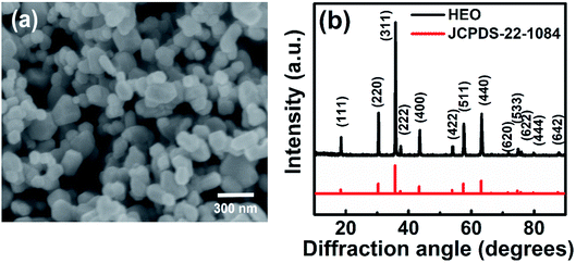 |
| | Fig. 1 (a) SEM image and (b) XRD pattern of HESO NPs. | |
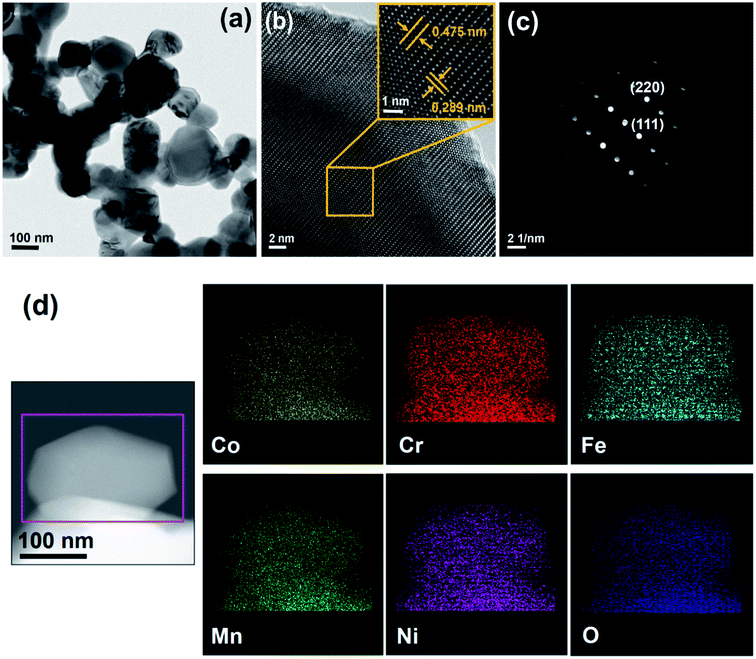 |
| | Fig. 2 (a) TEM, (b) HRTEM, (c) SAED, and (d) STEM mapping data of HESO NPs. | |
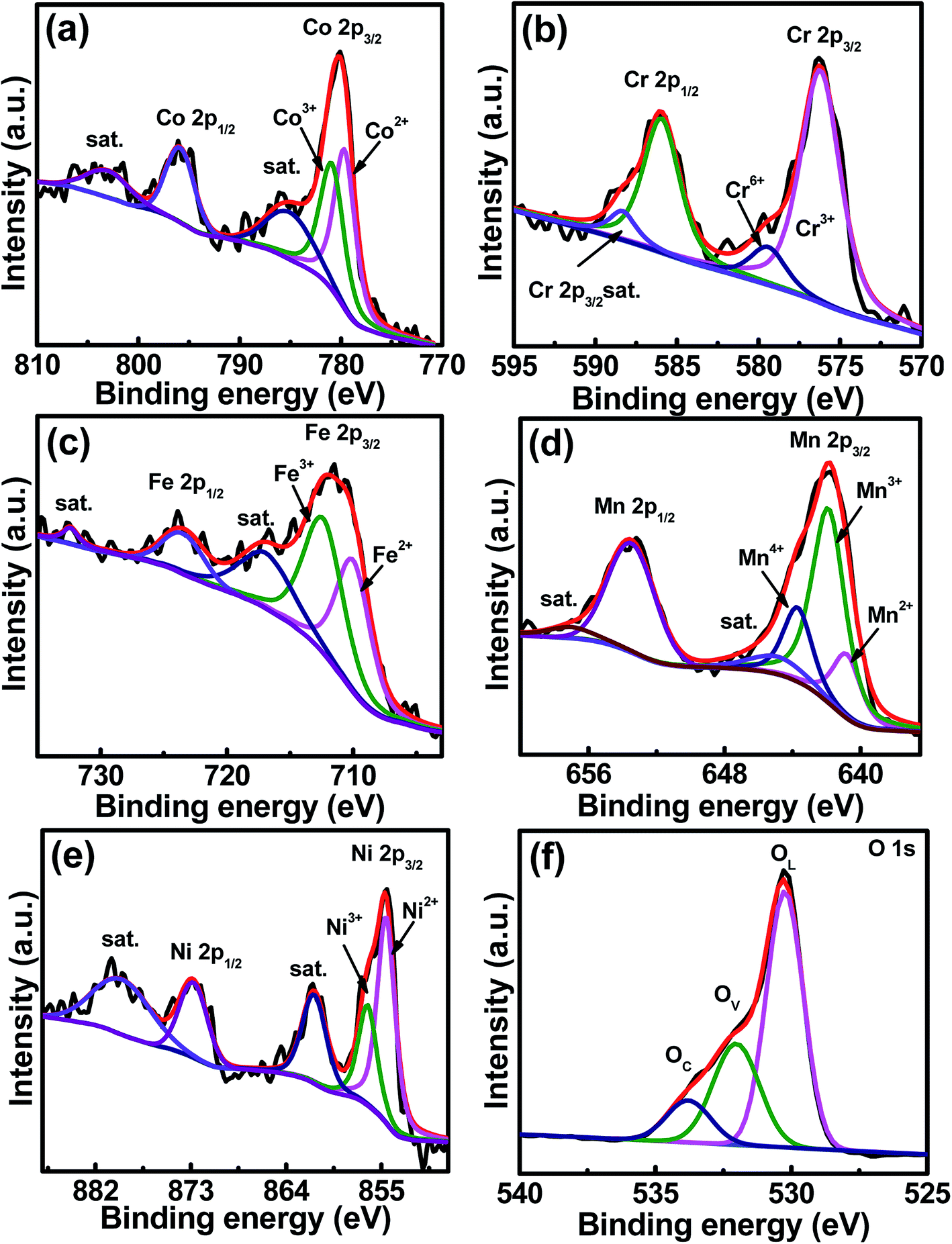
The core-level XPS spectra of Co 2p, Cr 2p, Fe 2p, Mn 2p, Ni 2p, and O 1s of the sample are shown in Fig. 3a–f, respectively. The Co 2p spectrum shows two major peaks at 780.1 and 796.2 eV, corresponding to Co 2p3/2 and Co 2p1/2 binding energies, respectively.33,34 Two satellite peaks are at 785.4 and 802.9 eV.35 The spectrum shows co-existence of Co2+ and Co3+, and the Co2+/Co3+ concentration ratio is 46.9/53.1. In the Cr 2p3/2 spectrum, Cr3+ and Cr6+ are seen at 576.2 and 579.2 eV, respectively,36 and Cr3+ dominates with a concentration of 87.2%, balanced by Cr6+. The peak at a binding energy of 586.2 eV represents the Cr 2p1/2 signal.34,37 The satellite peak of Cr 2p3/2 is at 587.7 eV, while the satellite peak of Cr 2p1/2 locates in between 598 and 600 eV,37,38 which is out of the scan range used in this study. In the Fe 2p spectrum, two peaks are seen at 711.5 and 723.7 eV, which are attributed to the spin–orbit peaks of Fe 2p3/2 and Fe 2p1/2, respectively.39 The Fe2+/Fe3+ ratio is 45.3/54.7. Two satellite peaks belonging to Fe 2p3/2 and Fe 2p1/2 are at 718.1 and 732.2 eV, respectively. The Mn 2p3/2 spectrum is centered at 642.5 eV, which can be deconvoluted into Mn2+ at 640.4 eV (17.8%), Mn3+ at 641.8 eV (61.6%), and Mn4+ at 643.6 eV (20.6%).34,36,40 The peaks at 646.1 and 658.0 eV are the satellite peaks of Mn 2p3/2 and Mn 2p1/2, respectively.41 The Mn 2p1/2 peak locates at a binding energy of 653.08 eV.34 The high-resolution XPS spectrum of Ni shows two spin–orbit peaks at 855.2 and 872.3 eV, which can be ascribed to Ni 2p3/2 and Ni 2p1/2, respectively. Deconvolution of Ni 2p3/2 shows two peaks at different energies. The peak at 854.4 eV is ascribed to Ni2+, having a concentration of 66.3%, while the other peak at 856.0 eV corresponds to Ni3+,42 having a concentration of 32.7%. Two satellite peaks were detected at the high-binding-energy side around 861.3 (Ni 2p3/2) and 879.8 (Ni 2p1/2) eV. The O 1s spectrum can be deconvoluted into three peaks at 530.1, 531.6, and 533.7 eV, which are assigned to the lattice oxygen OL, oxygen vacancies OV, and chemisorbed oxygen OC, respectively.43–46 The OL/OV/OC ratio was determined to be 59.2/29.3/11.5. The existence of high-valence Cr6+ and Mn4+ in the prepared HESO is attributed to the surface oxidation that could happen during the 900 °C heat treatment in air. We think that these species only exist on the sample surface because they were not detected in the XRD and TEM analyses.
 |
| | Fig. 3 XPS (a) Co 2p, (b) Cr 2p, (c) Fe 2p, (d) Mn 2p, (e) Ni 2p, and (f) O 1s spectra of HESO NPs. | |
Formation mechanism
As mentioned above, to synthesize the HESO NPs, CTAB was used as the surfactant, which serves as an efficient soft colloidal template for controlling the size and shape of the NPs.47 Prior to the hydrothermal synthesis, CTAB forms CTA+ and Br− in the solution and hydrolysis of urea takes place according to Reactions (1)–(3).48 Subsequently, during the hydrothermal process, metal hydroxycarbonates and carbonates form according to Reactions (4) and (5). After the heat treatment at 900 °C, spinel oxide forms, as shown in Reaction (6).48| | | CO(NH2)2 + H2O → 2NH3 + CO2 | (1) |
| | | CO2 + H2O → CO32− + 2H+ | (2) |
| | | NH3 + H2O → NH4+ + OH− | (3) |
| | | Mx+ + yCO32− + xOH− → M(OH)x.(CO3)y | (4) |
| |  | (6) |
(M = Co, Cr, Fe, Mn, and Ni).
The formation of spinel NPs is further described in Fig. S3.†
Electrochemical performance
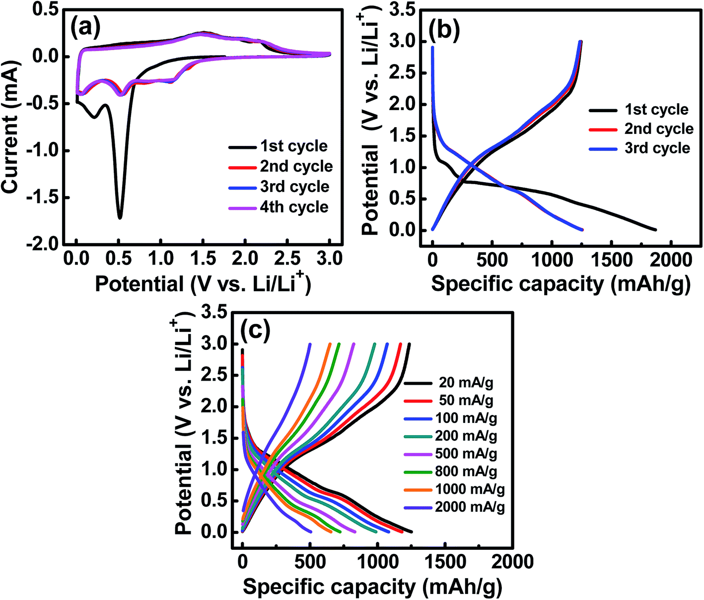
The electrochemical characteristics of the HESO anode were examined using CV. The obtained curves with multiple anodic and cathodic peaks, which are associated with Li+ insertion/extraction for the HESO, are shown in Fig. 4a. In the first negative (lithiation) scan, a huge irreversible peak at ∼0.5 V is seen. This can be ascribed to electrolyte decomposition and solid electrolyte interphase (SEI) formation together with some conversion reactions of the electrode.49,50 Afterward, another cathodic peak located at below 0.3 V emerges, indicating a further reduction of the HESO components at lower potentials. In the following positive scan, the anodic current before ∼1.2 V is steady, suggesting that the electrode delithiation rate was almost constant. There are multiple overlapped oxidation peaks in the potential region between 1.2 and 2.5 V, which are related to re-oxidation and/or re-conversion of the reduced species produced during the lithiation process.51,52 In the second cycle, the lithiation reactions are facilitated to launch at ∼1.5 V. It is noted that from the second cycle onward, the subsequent CV curves basically overlap, indicating good electrochemical reversibility and stability of the Li+ insertion/extraction reactions of the HESO electrode. Previously reported rock-salt (MgCoNiCuZn)O needs inactive MgO to stabilize the cycling charge–discharge performance.25 However, we have demonstrated that the spinel (MnFeCoNiCr)3O4, with all the cations being electroactive within the potential range, provides great redox stability.
 |
| | Fig. 4 (a) CV curves of the HESO electrode measured at a potential sweep rate of 0.1 mV s−1. (b) Initial three galvanostatic charge–discharge curves of the HESO electrode measured at 20 mA g−1. (c) Charge–discharge curves of the HESO electrode measured at various rates. | |
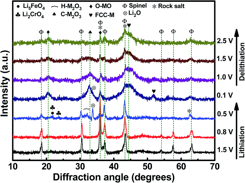
Fig. 5 shows a series of ex situ XRD patterns of the HESO electrode recorded after being charged/discharged to various potentials. At a lithiation potential of 0.8 V, the spinel structure was still intact since no significant Li+ uptake reaction had occurred (see Fig. 4a). When the electrode was lithiated to 0.5 V, the major peak at 35.7° clearly diminished. Phase transformation to a rock-salt type oxide, having a major peak at 43.1°, was recognized. The diffraction signals around 31° to 33° are identified to be hexagonal M2O3 (H-M2O3; JCPDS no. 40-1139) (M may include Mn, Fe, Co, Ni, and Cr). Moreover, the peak at 33.6° is ascribed to Li2O (JCPDS no. 12-0254), which shows that HESO conversion reactions have taken place. The small peaks at ∼21.6° and ∼23.6° cannot be exactly identified at the current stage. Further study on the lithiation products would require the use of synchrotron X-ray radiation to obtain stronger diffraction intensity. At 0.1 V, when the lithiation degree was further increased, the H-M2O3 phase disappeared, whereas several new diffraction peaks showed up. In addition to the face-centered cubic metallic phase (FCC-M; JCPDS no. 15-0806), orthorhombic MO (O-MO; JCPDS no. 04-0326) and cubic M2O3 (C-M2O3; JCPDS no. 39-0238) were seen, indicating a reductive reconstruction of the HESO. It is noted that the rock-salt phase remained at such a low potential. We believe that this is crucial for the electrode cycling stability, discussed in detail later. When the electrode was delithiated up to 2.5 V, with the rock-salt phase in the material, the O-MO and C-M2O3 phases continuously reduced. Meanwhile, the HESO phase was partially recovered, which can be supported by the re-appearance of the spinel (111) peak at 18.4° and the (222) peak at 37.4°. The recovery of the spinel phase is interesting and different from the XRD results reported for the rock-salt type HEO in the literature.15 For the conventional conversion-type anodes, the crystalline oxide phases are severely distorted and usually become nearly amorphous after the first charge–discharge cycle.53–55 However, a partial phase recovery is demonstrated here, which is responsible for the great electrode reversibility shown in the CV data. Also, the delithiation XRD patterns show that the FCC-M phase remains at 2.5 V. Basically, metallic phases are not stable and tend to oxidize at such a high potential.56,57 We believe that the entropy-dominated phase-stabilization effect plays a vital role.2,13 The multi-component HESO structure, together with the existence of oxygen vacancies, stabilizes the metallic phase. The co-existence of rock-salt and spinel phases after the first charge–discharge cycle is also supported by the high-resolution TEM and electron diffraction data, as shown in Fig. 6. The lattice spacings corresponding to the (111) and (311) planes of the HESO together with a distinct diffraction pattern are seen. In the same particle, the (111) and (200) planes of the rock-salt phase are also observed. Importantly, the recovery of the crystalline spinel phase is unique. The high entropy brings about a benefit of lowering the Gibbs free energy,15,58,59 which facilitates the regeneration of the HESO. TEM-EDS analysis was performed on the sample after one charge–discharge cycle. There is no apparent change in the elemental distribution, as shown in Fig. 6, confirming that the electrode material is still in a high entropy state.
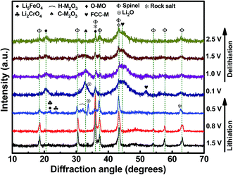 |
| | Fig. 5
Ex situ XRD patterns of HESO electrodes charged/discharged to various potentials. | |
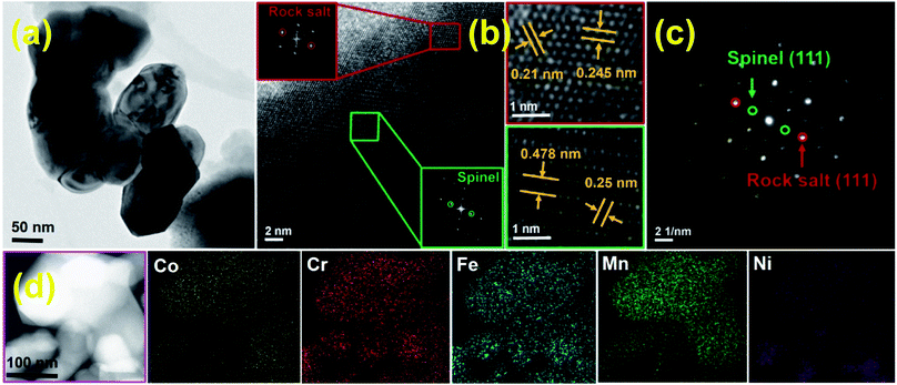 |
| | Fig. 6 (a) TEM, (b) HRTEM, (c) SAED, and (d) STEM mapping data of HESO NPs after the first charge–discharge cycle. | |
Three initial galvanostatic charge–discharge curves measured at 20 mA g−1 and various rates are shown in Fig. 4b and c, respectively. As shown in Fig. 4b, the first lithiation curve is characterized by a potential plateau at ∼0.5 V, which is consistent with the CV result (see Fig. 4a) and is associated with the SEI formation and some Li+ uptake reactions. The lithiation and delithiation capacities are 1869 and 1245 mA h g−1, respectively, corresponding to a first-cycle coulombic efficiency (CE) of ∼67%. We believe that this value can be further improved by using an electrode binder and electrolyte recipe optimization and by the use of a suitable surface coating on the HESO NPs. In the subsequent cycles, the reversible capacities are stable at ∼1235 mA h g−1, with the CE being above 99%. Fig. 4c shows the charge–discharge curves of the HESO electrode acquired at various current densities ranging from 20 to 2000 mA g−1. The measured delithiation capacities are 1170, 1072, 979, 824, 715, and 649 mA h g−1 at 50, 100, 200, 500, 800, and 1000 mA g−1, respectively. Even at a high rate of 2000 mA g−1, the electrode still can deliver a superior capacity of 500 mA h g−1. In general, conversion-type oxide anodes show a significant capacity deterioration at high current rates due to their low electronic conductivity and kinetic limitations of diffusion-driven redox processes during charging/discharging.60,61 In the literature, CNT@CuO delivered ∼275 mA h g−1 @ 1340 mA g−1, MnO delivered ∼150 mA h g−1 @ 1600 mA g−1, CuFeO2 delivered ∼280 mA h g−1 @ 1416 mA g−1, graphene@Fe2O3 delivered ∼425 mA h g−1 @ 2000 mA g−1, and (Co0.2Cu0.2Mg0.2Ni0.2Zn0.2)O rock-salt HEO delivered ∼280 mA h g−1 @ 1000 mA g−1.15,62–64 The great rate capability of the HESO electrode can be attributed to the increased electronic conductivity, since the metallic phases are distributed within the oxide after the first charge–discharge cycle (see Fig. 5). In addition, the multi-valence nature of the constituent elements in the HESO (see Fig. 3) promotes the formation of oxygen vacancies, as shown above, which are known to favor Li+ transport24 and thus high-rate charge–discharge capability.
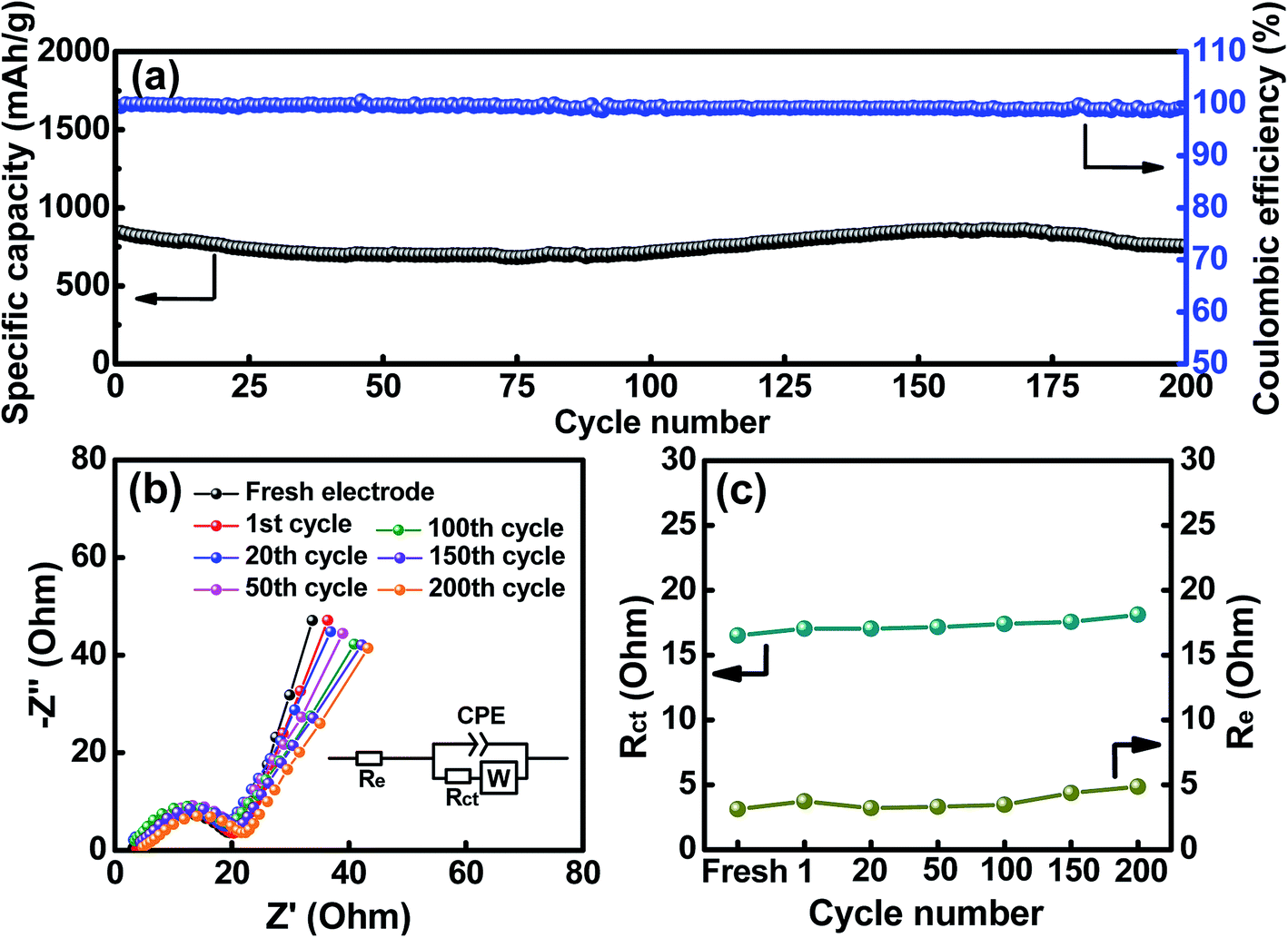
The cycling stability of the HESO electrode was evaluated, and the data obtained at a charge–discharge rate of 500 mA g−1 for 200 cycles are shown in Fig. 7a. The electrode shows a capacity retention ratio of approximately 90% after the cycling. This value can translate to an average capacity fading rate of 0.05% per cycle. As also shown in the figure, the CE values are around ∼99% up to 200 cycles, indicating great cyclability of the electrode. Some capacity fluctuations were observed during the cycling, and this phenomenon was repeatedly found for multiple cells. This behavior is probably related to the structural changes of the HESO and has also been reported for a rock-salt type HEO in the literature.15 The detailed mechanism is not clear yet. The much better cycling stability of the HESO electrode, compared to that of traditional conversion-type oxide electrodes,65–68 is associated with the entropy stabilization effects that maintain the crystalline oxide framework during the lithiation and promote the recovery of the spinel phase during the delithiation.15 This assures the redox durability of the electrode.
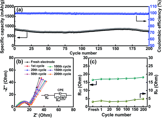 |
| | Fig. 7 (a) Cycling stability of the HESO electrode. (b) EIS spectra and (c) the obtained Re and Rct values of the HESO electrode measured after various charge–discharge cycles. | |
To further examine the impedance characteristics of the HESO electrode, EIS measurements were performed. Fig. 7b shows the spectra after various charge–discharge cycles. The Nyquist plots have intercepts at high frequencies, depressed semicircles at intermediate frequencies, and sloping lines at low frequencies. The equivalent circuit for these spectra is shown in the figure inset. Re represents the electrolyte resistance, Rct denotes the charge-transfer resistance between the active material and electrolyte, CPE is an interfacial constant phase element, and W represents the Warburg impedance corresponding to Li+ transport in the HESO electrode. As shown, the Rct values are small, which explains the superior electrode rate capability. After the first charge–discharge cycle, the Rct and W values do not change significantly upon the SEI formation. This means a low-impedance SEI layer is formed. Moreover, the increased impedance due to the SEI formation may be compensated by the enhanced electronic conductivity of the electrode because of the formation of the metallic phase after the first delithiation. Besides, the apparent Li+ diffusion coefficient in our HESO electrode calculated from the EIS data is 1.3 × 10⁻¹² cm2 s−1, which is considerably higher than those of reported spinel oxide anodes, as shown in Fig. S4.† In contrast to the mostly used conversion-type oxide anodes, whose Rct usually increases with cycling due to the agglomeration and pulverization of the active materials and the accumulation of the SEI film,69,70 in our case, the HESO electrode exhibits stable impedance characteristics up to 200 cycles. As shown in Fig. 7c, the Re and Rct values hardly increase with the cycle number. This explains the excellent capacity retention of this electrode after cycling.
In order to check the crystallinity of the HESO electrode after cycling (70 cycles), XRD analysis of the cycled electrode was carried out and the data are shown in Fig. S5.† The diffraction intensity of the cycled HESO electrode is low, indicating that the crystallinity reduces upon cycling. As shown in Fig. S6,† the HRTEM and SAED data confirm the existence of the crystalline rock-salt structure. The STEM mapping results indicate that all the elements homogeneously distribute throughout the particles. Fig. 8a and b show the XPS Li 1s and F 1s spectra of the cycled electrode. The Li 1s spectrum reveals that the major form of Li in the SEI is LiF. The F 1s spectrum shows a strong peak at ∼688.0 eV related to the PVDF binder and a characteristic LiF peak at ∼685.5 eV. These results reveal that LiF is an important component in the SEI film formed on the HESO electrode surface. As shown in Fig. 8c–g, divalent and trivalent states are seen for the Co, Fe, Mn, and Ni, whereas the Cr only shows a trivalent state. The Co2+/Co3+, Fe2+/Fe3+, Mn2+/Mn3+, and Ni2+/Ni3+ ratios are 56.5/43.5, 46.4/53.6, 49.1/50.9, and 62.7/37.3, respectively. It is noted that Mn4+ and Cr6+ were not found. This further confirms that the high-valence Cr6+ and Mn4+ cations found in the as-prepared HESO are related to surface oxidation. The O 1s spectrum can be fitted into the OL, OV, and OC components. The fraction of the OV clearly increases after cycling. The ratio of OL/OV/OC is 40.5/55.7/3.8.
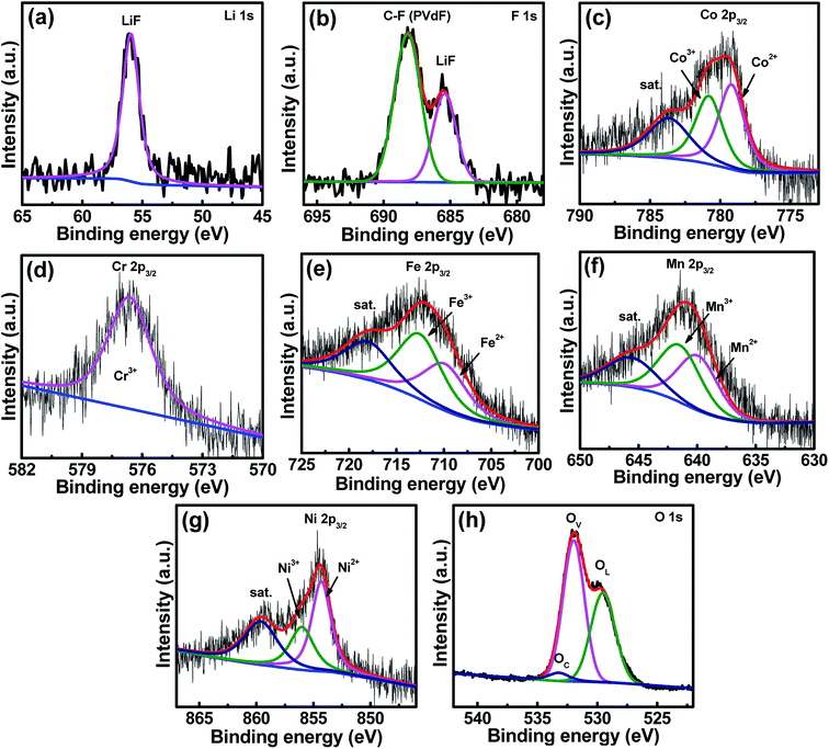 |
| | Fig. 8 XPS (a) Li 1s, (b) F 1s, (c) Co 2p, (d) Cr 2p, (e) Fe 2p, (f) Mn 2p, (g) Ni 2p, and (h) O 1s spectra of the HESO electrode after 70 charge–discharge cycles. | |
Fig. S7a and b† show the SEM morphologies of the electrode before and after 200 full charge–discharge cycles, respectively. Only a slight volume expansion of the HESO NPs was observed. No cracks (due to mechanical stress) and particle agglomeration, which are typical for the conventional conversion-type anodes, are seen on the cycled HESO electrode. For rock-salt (MgCoNiCuZn)O, it was found that after the first lithiation/delithiation cycle, even with inactive MgO stabilization, the structure almost disappeared, indicating the loss of crystalline ordering of the oxide. However, distinct XRD signals were clearly detected (see Fig. 5) for our HESO (with all cations being electroactive). This shows the role of the high entropy induced phase stabilization effects in the HESO. This is a unique feature of the HESO powder compared to the rock-salt HEOs reported previously. Due to the flexibility of filling the A and B sites in the spinel structure, a larger number of combinations are expected, meaning increased entropy. This results in a stabilized structure without the use of dummy MgO. Even though further mechanism study and material optimization are needed, the HESO anode has shown great potential for future LIB applications.
Conclusions
A facile surfactant-assisted hydrothermal method has been used to synthesize single-phase HESO NPs for use as a LIB anode. Due to the existence of high valence states of the constituent cations and without the use of inactive MgO structural pillars, an extraordinary reversible charge–discharge capacity of 1235 mA h g−1 has been demonstrated. A unique lithiation–delithiation mechanism of the HESO electrode has been explored through ex situ XRD analysis. The distributed metallic phases and oxygen vacancies within the HESO electrode ensure the high electronic conductivity and fast Li+ transport, respectively, leading to the great high-rate performance of the electrode (i.e., 500 mA h g−1 @ 2000 mA g−1). The much better cycling stability of the HESO electrode (90% capacity retention after 200 cycles), compared to that of conventional conversion-type oxide electrodes, is associated with the entropy stabilization effects that retain the crystalline oxide framework during lithiation and delithiation. The HESO NP anode opens a new window for the development of next-generation LIB electrode materials.
Conflicts of interest
There are no conflicts to declare.
Acknowledgements
This work has been supported by the Ministry of Science and Technology of Taiwan under Grant No MOST 107-2218-E-006-047 and MOST 108-2218-E-006-023.
References
- J. W. Yeh, S. K. Chen, S. J. Lin, J. Y. Gan, T. S. Chin, T. T. Shun, C. H. Tsau and S. Y. Chang, Adv. Eng. Mater., 2004, 6, 299–303 CrossRef CAS.
- C. M. Rost, E. Sachet, T. Borman, A. Moballegh, E. C. Dickey, D. Hou, J. L. Jones, S. Curtarolo and J.-P. Maria, Nat. Commun., 2015, 6, 8485 CrossRef CAS.
- A. Sarkar, R. Djenadic, D. Wang, C. Hein, R. Kautenburger, O. Clemens and H. Hahn, J. Eur. Ceram. Soc., 2018, 38, 2318–2327 CrossRef CAS.
- S. Jiang, T. Hu, J. Gild, N. Zhou, J. Nie, M. Qin, T. Harrington, K. Vecchio and J. Luo, Scr. Mater., 2018, 142, 116–120 CrossRef CAS.
- A. Sarkar, R. Djenadic, N. J. Usharani, K. P. Sanghvi, V. S. Chakravadhanula, A. S. Gandhi, H. Hahn and S. S. Bhattacharya, J. Eur. Ceram. Soc., 2017, 37, 747–754 CrossRef CAS.
- J. Zhou, J. Zhang, F. Zhang, B. Niu, L. Lei and W. Wang, Ceram, 2018, 44, 22014–22018 CAS.
- E. Castle, T. Csanádi, S. Grasso, J. Dusza and M. Reece, Sci. Rep., 2018, 8, 8609 CrossRef.
- P. H. Mayrhofer, A. Kirnbauer, P. Ertelthaler and C. M. Koller, Scr. Mater., 2018, 149, 93–97 CrossRef CAS.
- J. Gild, Y. Zhang, T. Harrington, S. Jiang, T. Hu, M. C. Quinn, W. M. Mellor, N. Zhou, K. Vecchio and J. Luo, Sci. Rep., 2016, 6, 37946 CrossRef CAS.
- T. Jin, X. Sang, R. R. Unocic, R. T. Kinch, X. Liu, J. Hu, H. Liu and S. Dai, Adv. Mater., 2018, 30, 1707512 CrossRef.
- C.-W. Tsai, S.-W. Lai, K.-H. Cheng, M.-H. Tsai, A. Davison, C.-H. Tsau and J.-W. Yeh, Thin Solid Films, 2012, 520, 2613–2618 CrossRef CAS.
- R.-Z. Zhang, F. Gucci, H. Zhu, K. Chen and M. J. Reece, Inorg. Chem., 2018, 57, 13027–13033 CrossRef CAS.
- A. Sarkar, Q. Wang, A. Schiele, M. R. Chellali, S. S. Bhattacharya, D. Wang, T. Brezesinski, H. Hahn, L. Velasco and B. Breitung, Adv. Mater., 2019, 1806236 CrossRef.
- H. Chen, J. Fu, P. Zhang, H. Peng, C. W. Abney, K. Jie, X. Liu, M. Chi and S. Dai, J. Mater. Chem. A, 2018, 6, 11129–11133 RSC.
- A. Sarkar, L. Velasco, D. Wang, Q. Wang, G. Talasila, L. de Biasi, C. Kübel, T. Brezesinski, S. S. Bhattacharya and H. Hahn, Nat. Commun., 2018, 9, 3400 CrossRef.
- D. Bérardan, S. Franger, D. Dragoe, A. K. Meena and N. Dragoe, Phys. Status Solidi RRL, 2016, 10, 328–333 CrossRef.
- J. Gild, M. Samiee, J. L. Braun, T. Harrington, H. Vega, P. E. Hopkins, K. Vecchio and J. Luo, J. Eur. Ceram. Soc., 2018, 38, 3578–3584 CrossRef CAS.
- K. Chen, X. Pei, L. Tang, H. Cheng, Z. Li, C. Li, X. Zhang and L. An, J. Eur. Ceram. Soc., 2018, 38, 4161–4164 CrossRef CAS.
- A. Sarkar, C. Loho, L. Velasco, T. Thomas, S. S. Bhattacharya, H. Hahn and R. Djenadic, Dalton Trans., 2017, 46, 12167–12176 RSC.
- J. Dąbrowa, M. Stygar, A. Mikuła, A. Knapik, K. Mroczka, W. Tejchman, M. Danielewski and M. Martin, Mater. Lett., 2018, 216, 32–36 CrossRef.
- M. Stygar, J. Dąbrowa, M. Moździerz, M. Zajusz, W. Skubida, K. Mroczka, K. Berent, K. Świerczek and M. Danielewski, J. Eur. Ceram. Soc., 2020, 40, 1644–1650 CrossRef CAS.
- Z. Grzesik, G. Smoła, M. Miszczak, M. Stygar, J. Dąbrowa, M. Zajusz, K. Świerczek and M. Danielewski, J. Eur. Ceram. Soc., 2020, 40, 835–839 CrossRef CAS.
- D. Wang, Z. Liu, S. Du, Y. Zhang, H. Li, Z. Xiao, W. Chen, R. Chen, Y. Wang and Y. Zou, J. Mater. Chem. A, 2019, 7, 24211–24216 RSC.
- D. Bérardan, S. Franger, A. Meena and N. Dragoe, J. Mater. Chem. A, 2016, 4, 9536–9541 RSC.
- N. Qiu, H. Chen, Z. Yang, S. Sun, Y. Wang and Y. Cui, J. Alloys Compd., 2019, 777, 767–774 CrossRef CAS.
- Q. Wang, A. Sarkar, Z. Li, Y. Lu, L. Velasco, S. S. Bhattacharya, T. Brezesinski, H. Hahn and B. Breitung, Electrochem. Commun., 2019, 100, 121–125 CrossRef CAS.
- Q. Wang, A. Sarkar, D. Wang, L. Velasco, R. Azmi, S. S. Bhattacharya, T. Bergfeldt, A. Düvel, P. Heitjans and T. Brezesinski, Energy Environ. Sci., 2019, 12, 2433–2442 RSC.
- C. Zhao, F. Ding, Y. Lu, L. Chen and Y. S. Hu, Angew. Chem., Int. Ed., 2020, 59, 264–269 CrossRef CAS.
- H. Chen, N. Qiu, B. Wu, Z. Yang, S. Sun and Y. Wang, RSC Adv., 2020, 10, 9736–9744 RSC.
- K. A. Jarvis, C.-C. Wang, A. Manthiram and P. J. Ferreira, J. Mater. Chem. A, 2014, 2, 1353–1362 RSC.
- M. Chen, D. Chen, Y. Liao, X. Zhong, W. Li and Y. Zhang, ACS Appl. Mater. Interfaces, 2016, 8, 4575–4584 CrossRef CAS.
-
B. S. Murty, J.-W. Yeh, S. Ranganathan and P. Bhattacharjee, High-entropy alloys, Elsevier, 2019 Search PubMed.
- P. W. Menezes, A. Indra, V. Gutkin and M. Driess, Chem. Commun., 2017, 53, 8018–8021 RSC.
- G. Allen, S. Harris, J. Jutson and J. Dyke, Appl. Surf. Sci., 1989, 37, 111–134 CrossRef CAS.
- R. Ding, L. Qi, M. Jia and H. Wang, Nanoscale, 2014, 6, 1369–1376 RSC.
- B. Bao, J. Liu, H. Xu, B. Liu, K. Zhang and Z. Jin, RSC Adv., 2017, 7, 8589–8597 RSC.
- I. Grohmann, E. Kemnitz, A. Lippitz and W. Unger, Surf. Interface Anal., 1995, 23, 887–891 CrossRef CAS.
- J. Tang, S. Ni, Q. Chen, X. Yang and L. Zhang, J. Alloys Compd., 2017, 698, 121–127 CrossRef CAS.
- T. Yamashita and P. Hayes, Appl. Surf. Sci., 2008, 254, 2441–2449 CrossRef CAS.
- M. Oku and K. Hirokawa, J. Electron Spectrosc. Relat. Phenom., 1976, 8, 475–481 CrossRef CAS.
- M. Langell, C. Hutchings, G. Carson and M. Nassir, J. Vac. Sci. Technol., A, 1996, 14, 1656–1661 CrossRef CAS.
- X. Zheng, Y. Zhang, H. Liu, D. Fu, J. Chen, J. Wang, C. Zhong, Y. Deng, X. Han and W. Hu, Small, 2018, 14, 1803666 CrossRef.
- J.-W. Kim, S. J. Lee, P. Biswas, T. I. Lee and J.-M. Myoung, Appl. Surf. Sci., 2017, 406, 192–198 CrossRef CAS.
- D. Li, Y. Gong, Y. Zhang, C. Luo, W. Li, Q. Fu and C. Pan, Sci. Rep., 2015, 5, 12903 CrossRef CAS.
- J. H. Kim, Y. J. Jang, J. H. Kim, J.-W. Jang, S. H. Choi and J. S. Lee, Nanoscale, 2015, 7, 19144–19151 RSC.
- J. Bao, X. Zhang, B. Fan, J. Zhang, M. Zhou, W. Yang, X. Hu, H. Wang, B. Pan and Y. Xie, Angew. Chem., Int. Ed., 2015, 54, 7399–7404 CrossRef CAS.
- M.-P. Pileni, Nat. Mater., 2003, 2, 145 CrossRef CAS.
- S. Abouali, M. A. Garakani, Z.-L. Xu and J.-K. Kim, Carbon, 2016, 102, 262–272 CrossRef CAS.
- X. Fan, J. Shao, X. Xiao, L. Chen, X. Wang, S. Li and H. Ge, J. Mater. Chem. A, 2014, 2, 14641–14648 RSC.
- F. Zou, Y.-M. Chen, K. Liu, Z. Yu, W. Liang, S. M. Bhaway, M. Gao and Y. Zhu, ACS Nano, 2015, 10, 377–386 CrossRef.
- N. Wang, X. Ma, Y. Wang, J. Yang and Y. Qian, J. Mater. Chem. A, 2015, 3, 9550–9555 RSC.
- K. Xiao, L. Xia, G. Liu, S. Wang, L.-X. Ding and H. Wang, J. Mater. Chem. A, 2015, 3, 6128–6135 RSC.
- C. Jo, W.-G. Lim, A. H. Dao, S. Kim, S. Kim, S. Yoon and J. Lee, J. Mater. Chem. A, 2017, 5, 24782–24789 RSC.
- Y. Deng, S. Tang, Q. Zhang, Z. Shi, L. Zhang, S. Zhan and G. Chen, J. Mater. Chem., 2011, 21, 11987–11995 RSC.
- H.-C. Liu and S.-K. Yen, J. Power Sources, 2007, 166, 478–484 CrossRef CAS.
- Y. Fu and A. Manthiram, Electrochim. Acta, 2013, 109, 716–719 CrossRef CAS.
- Y. Li, B. Tan and Y. Wu, Nano Lett., 2008, 8, 265–270 CrossRef CAS.
- A. Manzoor, S. Pandey, D. Chakraborty, S. R. Phillpot and D. S. Aidhy, npj Comput. Mater., 2018, 4, 47 CrossRef.
- Z. Lei, X. Liu, H. Wang, Y. Wu, S. Jiang and Z. Lu, Scr. Mater., 2019, 165, 164–169 CrossRef CAS.
- Y. Lu, L. Yu and X. W. D. Lou, Chem, 2018, 4, 972–996 CAS.
- J. Cabana, L. Monconduit, D. Larcher and M. R. Palacin, Adv. Mater., 2010, 22, E170–E192 CrossRef CAS.
- S.-F. Zheng, J.-S. Hu, L.-S. Zhong, W.-G. Song, L.-J. Wan and Y.-G. Guo, Chem. Mater., 2008, 20, 3617–3622 CrossRef CAS.
- W. Zhou, J. Zhu, C. Cheng, J. Liu, H. Yang, C. Cong, C. Guan, X. Jia, H. J. Fan and Q. Yan, Energy Environ. Sci., 2011, 4, 4954–4961 RSC.
- K. Zhong, X. Xia, B. Zhang, H. Li, Z. Wang and L. Chen, J. Power Sources, 2010, 195, 3300–3308 CrossRef CAS.
- L. Lu, J.-Z. Wang, X.-B. Zhu, X.-W. Gao and H.-K. Liu, J. Power Sources, 2011, 196, 7025–7029 CrossRef CAS.
- S. G. Mohamed, C.-J. Chen, C. K. Chen, S.-F. Hu and R.-S. Liu, ACS Appl. Mater. Interfaces, 2014, 6, 22701–22708 CrossRef CAS.
- G. Wang, Y. Chen, K. Konstantinov, M. Lindsay, H. Liu and S. Dou, J. Power Sources, 2002, 109, 142–147 CrossRef CAS.
- L. Zhou, D. Zhao and X. W. Lou, Adv. Mater., 2012, 24, 745–748 CrossRef CAS.
- J. Li, S. Hwang, F. Guo, S. Li, Z. Chen, R. Kou, K. Sun, C.-J. Sun, H. Gan and A. Yu, Nat. Commun., 2019, 10, 2224 CrossRef.
- M. H. Modarres, J. H.-W. Lim, C. George and M. De Volder, J. Phys. Chem. C, 2017, 121, 13018–13024 CrossRef CAS.
Footnote |
| † Electronic supplementary information (ESI) available. See DOI: 10.1039/d0ta04844e |
|
| This journal is © The Royal Society of Chemistry 2020 |
Click here to see how this site uses Cookies. View our privacy policy here. 
 Open Access Article
 This Open Access Article is licensed under a Creative Commons Attribution-Non Commercial 3.0 Unported Licence
 bc,
Jeng-Kuei
Chang
bc,
Jeng-Kuei
Chang