 Open Access Article
Creative Commons Attribution 3.0 Unported Licence
Fundamental promise of anthraquinone functionalized graphene based next generation battery electrodes: a DFT study†
Hristo G.
Rasheev
ab,
Rafael B.
Araujo
b,
Alia
Tadjer
 *a and
Patrik
Johansson
 *bc
*bc
aFaculty of Chemistry and Pharmacy, University of Sofia, 1164 Sofia, Bulgaria. E-mail: tadjer@chem.uni-sofia.bg
bDept. of Physics, Chalmers University of Technology, 412 96 Gothenburg, Sweden. E-mail: patrik.johansson@chalmers.se
cALISTORE-European Research Institute, CNRS FR 3104, Hub de l'Energie, 80039 Amiens, France
First published on 3rd July 2020
Abstract
Organic batteries are promising alternatives to the present rechargeable battery technologies, mainly due to projected lower fabrication costs, less environmental impact, more versatility, and chemical and mechanical flexibility. In this study we investigate potential organic battery electrodes composed of an electronically conductive graphene monolayer functionalized with redox-active anthraquinone (AQ). The combination overcomes common drawbacks of organic batteries: (i) the solubility of the organic redox-active materials in the electrolyte is mitigated by anchoring onto graphene and (ii) the need for a large amount of conductive additives in the composite electrode is circumvented by the high conductivity of graphene. The electrodes are modelled by various density functional theory (DFT) based approaches and their fundamental promise as part of Li, Ca, and Al based batteries are outlined. We model the design of the electrodes, such as AQ attachment and loading, the thermodynamics of accepting mono to trivalent ideal charge carriers from the electrolyte, i.e. Li+, Ca2+, and Al3+, and the kinetics of ion diffusion at the electrode surface by assessment of the activation barriers. From the calculated multi-step electrode potential profiles, the theoretical electrode energy densities, with respect to the redox-active part, are 570 and 512 W h kg−1 for Li and Ca, respectively, which is quite comparable to the active materials of inorganic medium voltage lithium-ion battery electrodes. As the average potentials are in the range 0.5–1.2 V vs. Mn+/M0 these materials are either to be used as negative electrodes, combined with a high or medium potential positive electrode, or as positive electrodes vs. metal electrodes, for low voltage battery application.
Introduction
Rechargeable battery technologies attract unabated research interest due to the continuously growing demand for all kinds of portable electronic devices and electrified vehicles, as well as an up-coming market of large-scale electrochemical stationary storage and redistribution of electricity obtained from renewable energy sources, etc. At present, the lithium-ion batteries (LIBs) are the totally dominant technology, but still carry some safety risks, cost issues, and constrained resource concerns.1,2 The latter is true for lithium itself and the negative electrode as natural graphite is a limited resource, as well as for the positive electrode, most notably the transition metals Co and Ni.3,4 Major research directions encompass the development of new LIB electrode designs with higher capacity and better capacity retention, as well as changing to other battery technologies using cheaper and more abundant metals than lithium and therefore Na+, K+, Mg2+, Ca2+, or Al3+ are considered as charge carriers.5–11The LIBs on the market today are all based on electrodes with inorganic active materials. A less expensive, less toxic, and “greener” alternative would be to use organic redox-active compounds.12,13 Furthermore, such compounds can easily be fabricated applying tailored organic synthesis and designed to be chemically robust during battery operation while easily degradable after disposal.14–16
As active materials, i.e. redox-active compounds, different carbonyl derivatives, such as quinones, especially anthraquinone (AQ), and thioquinones, are deemed the most promising building blocks due to their high rate of redox reactions, high specific capacity, structural variety, low cost and environmental safety.17–22 They are, however, electronically non-conducting and usually rather soluble in the electrolytes employed.23 This has traditionally been solved by attachment to a conducting matrix, usually polymers, such as PAQS,24–27 or carbon nanotubes/networks,28,29 but also graphene has been employed.30–32
2D materials in general,33 and graphene in particular,34 have recently drawn a great deal of attention for application in a variety of electrochemical energy storage devices. Graphene is an excellent electrical conductor and can thus also act as current collector, which solves a general problem of the organic battery electrodes – the need for a large content, up to 50%, of conductive carbon additives.35,36 To create functionalized graphene/graphene oxide battery electrodes, several routes have been proposed and developed: attaching organic residues via decomposition of diazonium salts,37–39 cycloaddition, such as Diels–Alder reactions, in which the graphene could be either the diene or the dienophile,40 and free radical photochemical reaction between graphene and benzoyl peroxide.41
Here we combine two of the above promises by looking at AQ grafted onto graphene and investigate the fundamental prospects of this combination as electrode for a set of battery technologies, using mono- (Li+), di- (Ca2+) and tri-valent (Al3+) charge carriers. Molecular modelling techniques such as density functional theory (DFT) and the climbing image nudged elastic band (cNEB) method are used to make an in silico and a priori unlimited assessment of both the thermodynamics possibilities, i.e. electrode capacity and voltage – important for the electrode energy density, and the kinetics limitations that may come into play, i.e. the ion diffusion at the electrode surface – important for the final battery power rate performance.
Computational
Methods
Most calculations were performed using the projector-augmented wave (PAW) method as implemented in the Vienna Ab initio Simulation Package (VASP).42,43 DFT was employed using the PBE functional44 for the exchange and the correlation energy together with the empirical dispersion term of Grimme (PBE + D2).45 The plane-waves were expanded with an energy cut-off of 600 eV and a Γ point was applied to integrate over the Brillouin zone (except for the density of states where a 4 × 4 × 1 k-mesh was used). The electron partial occupancies were obtained within the Gaussian smearing scheme together with a smearing parameter of 0.1 eV. The atomic coordinates were optimized towards convergence criteria of 0.01 eV Å−1 for all forces resulting in average |F|: 0.003 eV Å−1 and maximum |F|: 0.010 eV Å−1. For all practical purposes and as we are interested mainly in energy differences we use the DFT total energy as a proxy for the Gibbs free energy. Subsequently the charge distributions were calculated using Bader's quantum theory of atoms in molecules (QTAIM),46 as implemented in the Bader program.47 For single molecules and radicals the Gaussian 16 (G16) program48 was used at the PBE/6-31G* level of theory. The minimum energy pathways were calculated by the climbing image nudged elastic band method (cNEB).49,50 The reaction pathways were modelled by linearly interpolating 6 to 7 images between the equilibrium positions and calculating the activation barriers as the energy difference between the initial state and the transition state. AIMD simulations were performed with VASP to generate trajectories of Li+ dynamics at the electrode surfaces, using a 1 fs time-step and 20 ps equilibration time in the canonical NVT ensemble at 700 K. VESTA was used for visualisation of optimised structures.51Models
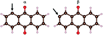
The models comprise the metal-ion charge carriers as atoms (M), AQ incl. its radicals, and AQ covalently anchored to graphene. Due to the D2h symmetry of AQ, there are only two unique ways to produce an AQ radical: α and β (Fig. 1). These were optimized (PBE, G16) and the β-radical was found to be more stable by ca. 9 kJ mol−1.As graphene “substrate” a large enough fragment is needed to accommodate a sufficient number of AQs with different topologies and orientations, while maintaining a reasonable computational cost. A hexagonal periodic box of a = 1.481 nm and c = 3.000 nm, containing 72 carbon atoms (6 × 6 rings), was chosen for the VASP calculations. The size of the c dimension provides a sufficient vacuum slab of ca. 2 nm to isolate the layer from its periodic images.
For the resulting AQC72 system, there are three dissimilar orientations the AQ can have with respect to the graphene substrate (Fig. 2), and hence a total of six isomeric starting structures (with AQ α- and β-radicals both being considered).
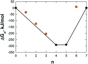
C72 allows the attachment of no more than 7 AQs. The most favourable AQ coverage, i.e. n in AQnC72, was determined for n = 0–7 by computing the relative free energy of formation, ΔGn, for the most stable isomer of each, as:52
 | (1) |
After having established the optimal AQ loading, the metal-electrode interaction modelling used a stepwise addition of M atoms (M = Li, Ca, and Al), to mimic the acceptance of the corresponding Mn+ charge carriers. Starting with Li, one Li atom was added at eight different locations covering all symmetrically non-equivalent positions and this process was repeated with two Li atoms at four different positions, taking into account the most stable structures from the previous step. Subsequently, two Li atoms at a time were added until the intercalation became energetically unfavourable (16 Li). The same procedure was repeated with Ca (up to 8 Ca), while Al was introduced one atom at a time up to 4 atoms.
The electrode potential profile was obtained by first calculating the step-wise free energy variation as:
| ΔG = G(Mx2AQnC72) − [(x2 − x1)G(M(s)) + G(Mx1AQnC72)] | (2) |
| E = −ΔG/(zF) | (3) |
From the above, both the capacity and the electrode gravimetric energy density were calculated as:
 | (4) |
 | (5) |
The diffusion coefficients for the ionic migration were calculated as:
| D = d2ν0 exp(−Ea/kBT) | (6) |
Results and discussion
We first compute the most favourable design of our new organic–graphene composite electrodes and then we investigate the possible adsorption sites for Li/Ca/Al and their interaction with the electrodes. Subsequently, the electrode capacities and the energy densities were calculated. Finally, the Mn+ dynamics at the electrode surface was assessed via the activation barriers for possible diffusion paths.Electrode design
The electrode design has to take into consideration several issues: (i) the most favourable manner of attachment of AQ to graphene, (ii) the optimal loading and topology of AQ, safeguarding also the electric conductivity of the graphene substrate, and (iii) the relative orientation of AQ minimizing steric repulsion and providing sufficient space for metal adsorption and diffusion.First we performed six separate geometry optimizations (VASP, cut-off = 350 eV) of a single AQ attached to graphene, covering the three possible orientations (Fig. 2) of the α- and β-AQ radicals (Fig. 1). All α-bonded structures result in severe out-of-plane deformation of both AQ and graphene, due to steric repulsion between graphene and the closest AQ hydrogen and oxygen atoms (Fig. S1a†). In contrast, the β-bonded structures exhibit minor out-of-plane deformation only for graphene at the connecting site and are 58–106 kJ mol−1 more stable than the most stable α-bonded structure (Fig. S1b†). The β-bonded structure in orientation 1 was chosen for all further investigations.
The optimal loading of AQ in AQnC72 was determined from eqn (1) and n = 4 and n = 5 were found to be the two most, and almost equally, stable structures (Table S1† and Fig. 3). While n = 4 has one less AQ, and thus intrinsically has a lower capacity as electrode, it was chosen for further studies as it is less crowded and thus allows for both better access and surface diffusion of Mn+.
In addition, AQ4C72 is quite robust, due to the fact that the π-electron system of the graphene remains a well-conjugated and stable closed-shell Kekulè structure also after anchoring the four AQs (Fig. 4).
Thus the creation of AQ4C72 is not expected to affect the electrical conductivity of graphene detrimentally. This is further confirmed by the projected density of states and partial charge density (Fig. S2†) that demonstrate the contributions to the density of states close to the Fermi level mostly coming from pz states (π system) of the carbon atoms in the sheet.
Adsorption sites for M and resulting electrode capacities and energy densities
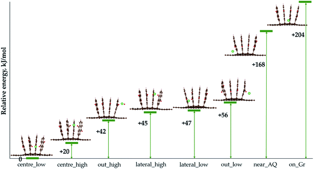
We now turn to the actual use of AQ4C72 as organic electrode. Starting with M = Li, LixAQ4C72, the lowest energy configurations for every number of Li atoms added were determined.For a single Li atom, i.e. LiAQ4C72, the two most stable structures are when Li is coordinated by three oxygen atoms from three different AQs (Fig. 5), while the most unfavourable structures are when Li interacts with the graphene sheet and one (near_AQ) or two (on Gr) hydrogen atoms from the AQs.
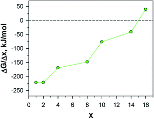
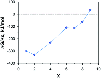
Subsequently, for Li2AQ4C72, the most favourable configuration is again three-fold oxygen atom coordination, with the two lithium atoms positioned symmetrically at opposite sides (Fig. 6b). Upon further addition of Li, the process eventually becomes endoergic for Li16AQ4C72 (Fig. 7 and Table S2†). In all structures, the most favourable positions are adjacent to the oxygen atoms until each of the eight possible sites have been lithiated (Fig. 6a–e), whereafter the most stable positions are Li sandwiched between two neighbouring AQ benzene moieties (Fig. 6f–h). The presence of metal atoms does not invoke any electrode expansion; on the contrary LixAQ4C72x = 8–16 are all more compact structures than AQ4C72. This is quite interesting and remarkable, and also promising, bearing in mind that volumetric expansion upon charging is a common and serious practical electrode problem e.g. the +300% expansion for LIB Si-anodes when forming Li4.4Si.54 Furthermore, adsorption of Li at the graphene surface in the more crowded LixAQ4C72 structures does not cause any noticeable structural defects, instead, the slight non-planarity is reduced.
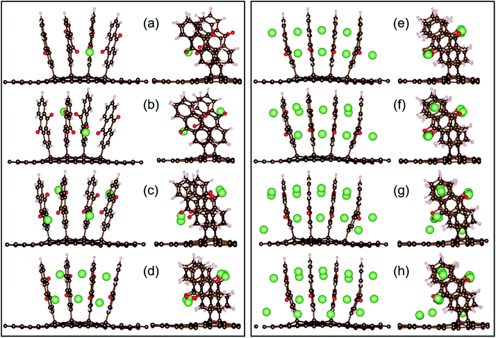 | ||
| Fig. 6 Two views of the most stable configurations of LixAQ4C72 for x = 1, 2, 4, 6, 8, 10, 14, and 16 (a–h, respectively). | ||
For all the structures above the main type of interaction can be deduced from the analysis of the electron density and of special interest for use as electrodes is the charge transfer and distribution. The calculated Bader charges reveal that the main charge transfer is ionic and to AQ, as expected, and only for the most lithiated systems some charge transfer to the graphene occurs – at most ca. 7% for Li14AQ4C72 (Fig. 8). The linear dependence of the Lix charge on x shows that the charge on lithium remains constant and sufficiently high (ca. +0.9) upon Li-enrichment of the material. Beyond insertion of 12 Li atoms the Li charge remains essentially the same, but the graphene negative charge increases at the expense of that of AQ.
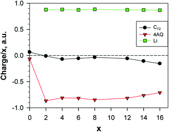 | ||
| Fig. 8 Normed charges of the Li atoms, the AQs and the graphene; a.u. = 1.6 × 10⁻¹⁹ C; the point x = 0 shows the charge distribution between Gr and AQ4. | ||
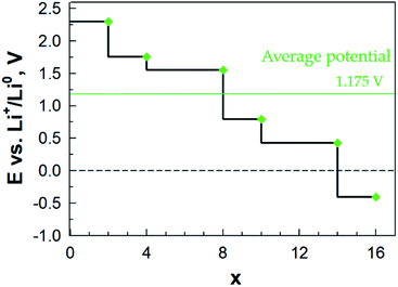
Finally, from the calculated free energy of formation for LixAQ4C72 we obtain the electrode electrochemical potential profile (eqn (3)) (Fig. 9). Starting at ca. 2.30 V vs. Li+/Li0, the first drop in potential is related to the change in the Li coordination between x = 2 and x = 3 and the second major drop also occurs when there is a major change in the Li coordination and all the preferred sites have been filled, x = 8, and the remaining Li atoms must reside between the AQ benzene moieties. From this the electrochemical potential certainly seems correlated with the type of Li coordination.
Second, the electrode capacity was calculated (eqn (4)) to be 453 mA h g−1 and third, by integrating the potential profile (eqn (5)), the gravimetric electrode energy density was estimated to be 570 W h kg−1. Both values are here for the organic redox-active part (AQ4), while if we take into account the entire electrode (AQnC72), we arrive at significantly more modest values: 222 mA h g−1 and 279 W h kg−1 (Table S8†). Neither of these measures are totally fair to be compared with traditional electrodes as we also assume a role as current collector for the graphene. With this caveat, the former measure provides twice the experimentally measured capacity of pure AQ, reported to be 217 mA h g−1 (ref. 55) and a theoretical gravimetric energy density comparable to the cathode active materials LiFePO4 (544 W h kg−1) and LiMn2O4 (548 W h kg−1).56
Using the same computational approach, for M = Ca we find that the first atom preferentially occupies the identical position as Li; threefold coordinated to the AQ oxygen atoms closest to the graphene sheet (Fig. 10a). Again, as for Li, the symmetrically equivalent position at the opposite side is the most favourable for the second Ca atom (Fig. 10b). Overall, however, the optimised geometries (Fig. 10a–f) and the free energies (Fig. 11 and Table S4†) demonstrate that unlike Li, Ca allows for favourable insertion of a maximum of eight atoms, each coordinating two oxygen atoms, thus, surpassing the Li system, capable of donating 16 electrons to the electrode. Though, as compared to Li, the distribution of the Ca atoms is not so uniform and the AQs are not so perfectly aligned. No sandwich structures were feasible, most probably due to insufficient space between the AQs for the larger Ca.
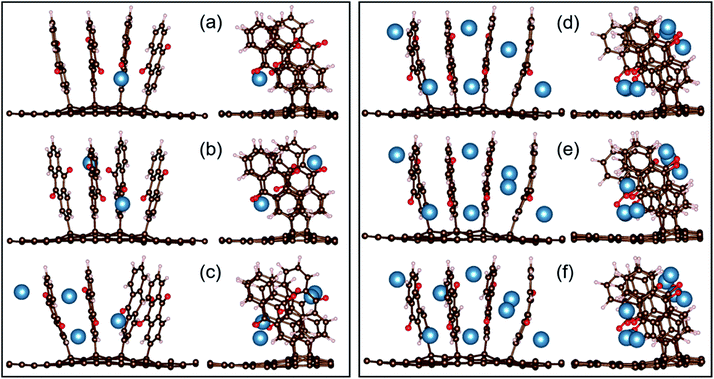 | ||
| Fig. 10 Two views of the optimized configurations of CaxAQ4C72 for x = 1, 2, 4, 6, 7, and 8 (a–f, respectively). | ||
The charge transfer from the Ca atoms to the electrode is a little bit less, ca. 75%, as compared both to Li and Al (87–89%) (Tables S3, S5 and S7†). The average charge per Ca is, just as for Li, constant up to Ca7AQ4C72 and then decreases slowly. The donated electron density is again concentrated mostly on the AQs but is shared more sizably with graphene even for x = 4 (Fig. 12).
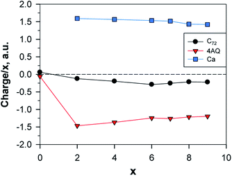 | ||
| Fig. 12 Normed charges of the Ca atoms, the AQs and the graphene; a.u. = 1.6 × 10⁻¹⁹ C; the point x = 0 shows the charge distribution between Gr and AQ4. | ||
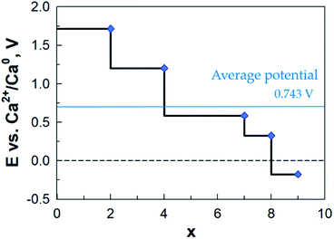
The calculated potential profile (Fig. 13) has a substantially lower starting value: ca. 1.7 V vs. Ca2+/Ca0 as compared to LixAQ4C72 (and thus also on an absolute scale as Li and Ca differ by a mere 170 mV). The three large drops in the potential after coordination of 2, 4 and 8 Ca atoms can be associated, respectively, with: (1) a change in the Ca coordination number from 3 to 2; (2) the oxygen atoms of the electrode not being able to accommodate more charge transferred from Ca; and (3) the saturation of the coordination capacity of the oxygen atoms. From all of this, the maximum number of favourably inserted Ca atoms corresponds to an electrode capacity of 517 mA h g−1 (253 mA h g−1) and a gravimetric electrode energy density of 512 W h kg−1 (251 W h kg−1) (Table S8†).
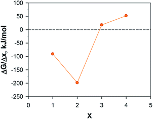
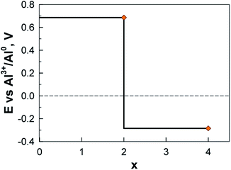
In contrast to Li and Ca, the Al system is truly exergonic only for AlAQ4C72 and Al2AQ4C72 (Fig. 14 and Table S6†). The coordination of the first two Al atoms is similar to the corresponding Li and Ca structures. The coordination of the next two Al atoms is tolerably endothermic, and thus, given our many simplifications, these should not be ruled out to be possible to create experimentally. However, they are accompanied by a substantial deformation of the electrode – the parallel configuration of the AQs is distorted and the non-planarity of the graphene is enhanced (Fig. 15).
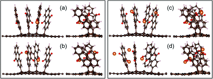 | ||
| Fig. 15 Two views of the optimized configurations of AlxAQ4C72 for x = 1, 2, 3, and 4 (a–d, respectively). | ||
With respect to the charge transfer to the graphene part of the electrode, the charge distribution (Table S7† and Fig. 16) resembles more the Li than the Ca system; in the metal-richest exergonic structures the proportion of the charge transferred to graphene is 6.7% for Li; 15% for Ca and 0.35% for Al. In terms of maximum charge, Al behaves more like Li at low degree of alumination and further on, more like Ca as both have 20% less charge than the nominal charges of Al3+ and Ca2+, respectively, while for Li the difference is only 10%.
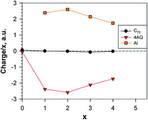 | ||
| Fig. 16 Normed charges of the Al atoms, the AQs and the graphene; a.u. = 1.6 × 10⁻¹⁹ C; the point x = 0 shows the charge distribution between Gr and AQ4. | ||
The calculated potential profile for AlxAQ4C72 renders correspondingly much lower electrode capacity and gravimetric electrode energy density: 194 mA h g−1 (95 mA h g−1) and 133 W h kg−1 (65 W h kg−1) for Al2(AQ)4C72 (Fig. 17) (Table S8†).
Activation barriers for Mn+ electrode surface diffusion
All the above reasoning and calculations provide only an energetic picture of these electrodes. However, a restricted ionic diffusion at the electrode surface might limit the kinetics and hence ultimately the battery power rate performance. To gain general insight in the dynamics of a Mn+ ion at the electrode surface, i.e. for MAQ4C72, we started with the Li system and performed AIMD simulations for Li14AQ4C72, chosen to provide enough statistics. Together with the high temperature used (700 K) the vast amount of Li may also enhance sampling. From the AIMD Li+ trajectories the most likely migration paths were established and subsequently, assuming these paths, the activation barriers for ionic diffusion for the LixAQ4C72, CaxAQ4C72, and AlxAQ4C72 systems were evaluated using cNEB.The Li+ trajectories first of all show how the ionic diffusion occurs in the vicinity of the AQs of the same conjugated block and without moving through the graphene layer; three distinct energy minima and three pathways are discernible (Fig. 18). Two of these paths have a Li+ moving between two AQs while the third connects two AQs with the graphene surface. The corresponding minimum energy paths (MEPs) are displayed in Fig. S3.†
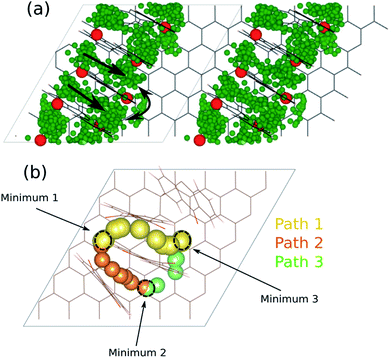 | ||
| Fig. 18 (a) Li+ trajectories for Li14AQ4C72 and (b) the resulting energy minima and diffusion pathways. | ||
From the cNEB calculations we obtain activation barriers for Li+ of ca. 80–140 kJ mol−1, corresponding to Li+ diffusion coefficients on the order of 10−20 to 10−31 m2 s−1 (Table 1) and only the lower energy paths, path 1 and path 3, will likely be active and relevant (D ≈ 10−20 m2 s−1). A fast comparison with e.g. the bulk Li+ diffusion in the standard LIB electrolyte, 1 M LiPF6 in EC:DMC (D ≈ 10−9 m2 s−1),57 might seem discouraging. However, the distance across the separator is typically ca. 25 μm, while these pathways within the electrode concern distances on the order of nm and hence four orders of magnitude shorter.
| Path# | Li+ | Ca2+ | Al3+ | |||
|---|---|---|---|---|---|---|
| E a [kJ mol−1] | D [m2 s−1] | E a [kJ mol−1] | D [m2 s−1] | E a [kJ mol−1] | D [m2 s−1] | |
| 1 | 84 | ≈10−21 | 144 | ≈10−32 | 202 | ≈10−42 |
| 2 | 132 | ≈10−31 | 142 | ≈10−31 | 226 | ≈10−46 |
| 3 | 79 | ≈10−20 | 167 | ≈10−36 | 166 | ≈10−36 |
For Ca2+ and Al3+, however, we know that the kinetics is even more sluggish and here the diffusion coefficients vary from 10−32 to 10−36 m2 s−1 for Ca2+ to 10−34 to 10−45 m2 s−1 for Al3+. Even if it is hard to directly compare with intercalation compounds, as our coordination type electrodes intrinsically are sparse, Dompablo et al.11 stated that a D ≈ 10−16 m2 s−1 or higher is a prerequisite for a promising battery electrode material – and hence we obtain much too low kinetics by our diffusion pathways.
Concluding remarks
Combining the conducting properties of graphene with the enhanced affinity for active metals of oxygen-containing non-conducting organics, we have successfully designed and characterised in silico a new class of electrode materials. The optimal loading of the organic redox molecule AQ as well as the optimal cation coordination has been obtained for three different charge carriers and thus battery concepts (Li, Ca, and Al). Notably, some reach both high capacity and gravimetric energy density, moreover, without any volume expansion. For the larger cation, Ca2+, we foresee that the capacity and energy density, could be even further enhanced by modifying the electrode design to allow penetration of Ca between the AQ planes, which would also be accompanied with volume contraction. On the other hand, the Al3+ coordination to the electrodes invokes a drastic, and possibly detrimental, structural deformation of the graphene. In reality, however, the coordination in the Al metal–organic batteries so far created, is based on AlCl2+ being the electroactive species,27 which might affect the electrode significantly less. The kinetics at the electrode surface might be a more complicating factor; we obtain quite high activation barriers and low diffusion coefficients for all the cations, especially for the multivalent ones. Yet, the exact engineering of a coordination type organic–graphene electrode will differ substantially from one made of traditional intercalation compounds as active materials which is why this measure might be less important – alongside the fact that the diffusing species might not be the “free” cation itself. We also have to take into account that we made the rather general assumption that all three cations would follow the same pathways. Overall, the results show that the combination of an organic redox centre grafted on a graphene backbone bears fundamental promise for a variety of modern battery designs.Conflicts of interest
There are no conflicts to declare.Acknowledgements
This work was funded in part by the EU H2020-FETOPEN CARBAT project (#766617) (R. B. A and P. J). H. R. acknowledges support from the EU ERASMUS+ program and P. J. acknowledges the continuous support for battery-related research from several Areas of Advance at Chalmers University of Technology (Materials Science, Energy, and Transport).References
- M. Li, J. Lu, Z. Chen and K. Amine, Adv. Mater., 2018, 30(33), 1800561 CrossRef PubMed.
- I. Tsiropoulos, D. Tarvydas, and N. Lebedeva, Li-ion batteries for mobility and stationary storage applications, JRC Science for Policy Report, EU Commission, 2018, DOI:10.2760/87175.
- H. Vikström, S. Davidsson and M. Höök, Appl. Energy, 2013, 110, 252–266 CrossRef.
- N. T. Nassar, T. E. Graedel and E. M. Harper, Sci. Adv., 2015, 1(3), e1400180 CrossRef CAS PubMed.
- N. Yabuuchi, K. Kubota, M. Dahbi and S. Komaba, Chem. Rev., 2014, 114(23), 11637 CrossRef PubMed.
- J.-Y. Hwang, S.-T. Myung and Y.-K. Sun, Chem. Soc. Rev., 2017, 46, 3529–3614 RSC.
- S. Komaba, T. Hasegawa, M. Dahbi and K. Kubota, Electrochem. Commun., 2015, 60, 172–175 CrossRef CAS.
- J. C. Pramudita, D. Sehrawat, D. Goonetilleke and N. Sharma, Adv. Energy Mater., 2017, 7(24), 1602911 CrossRef.
- J. Muldoon, C. B. Bucur and T. Gregory, Chem. Rev., 2014, 114, 11683–11720 CrossRef CAS PubMed.
- G. A. Elia, K. Marquardt, S. Fantini, R. Lin, E. Knipping, W. Peters, J. F. Drillet, S. Passerini, R. Hahn and K. Hoeppner, Adv. Mater., 2016, 28, 7564–7579 CrossRef CAS PubMed.
- M. E. Arroyo de Dompablo, A. Ponrouch, P. Johansson and M. R. Palacín, Chem. Rev., 2019 DOI:10.1021/acs.chemrev.9b00339.
- M. Armand and J. M. Tarascon, Nature, 2008, 451, 652–657 CrossRef CAS PubMed.
- D. Larcher and J. M. Tarascon, Nat. Chem., 2015, 7, 19–29 CrossRef CAS PubMed.
- P. Poizot and F. Dolhem, Energy Environ. Sci., 2011, 4, 2003–2019 RSC.
- X.-P. Gao and H.-X. Yang, Energy Environ. Sci., 2010, 3, 174–189 RSC.
- Z. Song and H. Zhou, Energy Environ. Sci., 2013, 6, 2280–2301 RSC.
- K. Kim, T. Liu, S. Lee and S. Jang, J. Am. Chem. Soc., 2016, 138, 2374–2382 CrossRef CAS PubMed.
- Y. Liang, Z. Tao and J. Chen, Adv. Energy Mater., 2012, 2, 742–769 CrossRef CAS.
- B. Häupler, A. Wild and U. S. Schubert, Adv. Energy Mater., 2015, 5(11), 1402034 CrossRef.
- K. Zhang, C. Guo, Q. Zhao, Z. Niu and J. Chen, Adv. Sci., 2015, 2, 1500018 CrossRef PubMed.
- S. Maniam, K. Oka and H. Nishide, MRS Commun., 2017, 7, 967 CrossRef CAS.
- T. Sotomura, H. Uemachi, K. Takeyama, K. Naoi and N. Oyama, Electrochim. Acta, 1992, 37, 1851–1854 CrossRef CAS.
- S. Muench, A. Wild, C. Friebe, B. Häupler, T. Janoschka and U. S. Schubert, Chem. Rev., 2016, 116(16), 9438–9484 CrossRef CAS PubMed.
- T. Suga, H. Ohshiro, S. Sugita, K. Oyaizu and H. Nishide, Adv. Mater., 2009, 21, 1627–1630 CrossRef CAS.
- T. Suga, S. Sugita, H. Ohshiro, K. Oyaizu and H. Nishide, Adv. Mater., 2011, 23(6), 751–754 CrossRef CAS PubMed.
- W. Deng, X. Liang, X. Wu, J. Qian, Y. Cao, X. Ai, J. Feng and H. Yang, Sci. Rep., 2013, 3, 2671 CrossRef PubMed.
- J. Bitenc, N. Lindahl, A. Vizintin, M. Abdelhamid, R. Dominko and P. Johansson, Energy Storage Materials, 2019, 24, 379–383 CrossRef.
- L. C. Cao, S. Sadaf, S. M. Beladi-Mousavi and L. Walder, Eur. Polym. J., 2013, 49, 1923–1934 CrossRef CAS.
- Q. Huang, D. Choi, L. Cosimbescu and J. P. Lemmon, Phys. Chem. Chem. Phys., 2013, 15, 20921–20928 RSC.
- Y.-X. Yu, J. Mater. Chem. A, 2014, 2, 8910–8917 RSC.
- S. Sertkol, B. Esat, A. Momchilov, M. Yilmaz and M. Sertkol, Carbon, 2017, 116, 154–166 CrossRef.
- C. Zhou, T. Gao, Q. Liu, Y. Wang and D. Xiao, Electrochim. Acta, 2020, 336, 135628 CrossRef CAS.
- B. Anasori, M. Lukatskaya and Y. Gogotsi, Nat. Rev. Mater., 2017, 2(2), 1–17 Search PubMed.
- R. Raccichini, A. Varzi, S. Passerini and B. Scrosati, Nat. Mater., 2015, 14, 271–279 CrossRef CAS PubMed.
- K. Pirnat, J. Bitenc, I. Jerman, R. Dominko and B. Genorio, ChemElectroChem, 2014, 1(12), 2131–2137 CrossRef CAS.
- H. Kim, H. Lim, S. Kim, J. Hong, D. Seo, D. Kim, S. Jeon, S. Park and K. Kang, Sci. Rep., 2013, 3, 1506 CrossRef PubMed.
- Y. Song, Y. Gao, H. Rong, H. Wen, Y. Sha, H. Zhang, H.-J. Liu and Q. Liu, Sustainable Energy Fuels, 2018, 2, 803 RSC.
- R. Sharma, J. H. Baik, C. J. Perera and M. S. Strano, Nano Lett., 2010, 10, 398–405 CrossRef CAS PubMed.
- J. Greenwood, T. H. Phan, Y. Fujita, Z. Li, O. Ivasenko, W. Vanderlinden, H. van Gorp, W. Frederickx, G. Lu, K. Tahara, Y. Tobe, H. Uji-I, S. F. L. Mertens and S. de Feyter, ACS Nano, 2015, 9(5), 5520–5535 CrossRef CAS PubMed.
- S. Sarkar, E. Bekyarova, S. Niyogi and R. C Haddon, J. Am. Chem. Soc., 2011, 133, 3324–3327 CrossRef CAS PubMed.
- H. T. Liu, S. M. Ryu, Z. Y. Chen, M. L. Steigerwald, C. Nuckolls and L. E. Brus, J. Am. Chem. Soc., 2009, 131, 17099–17101 CrossRef CAS PubMed.
- G. Kresse and J. Hafner, Phys. Rev. B: Condens. Matter Mater. Phys., 1993, 47, 558–561 CrossRef CAS PubMed.
- G. Kresse and J. Furthmüller, Phys. Rev. B: Condens. Matter Mater. Phys., 1996, 54, 11169–11186 CrossRef CAS PubMed.
- J. P. Perdew, K. Burke and M. Ernzerhof, Phys. Rev. Lett., 1996, 77, 3865–3868 CrossRef CAS PubMed.
- S. Grimme, J. Comput. Chem., 2006, 27, 1787–1799 CrossRef CAS PubMed.
- R. Bader, Acc. Chem. Res., 1985, 18(1), 9–15 CrossRef CAS.
- W. Tang, E. Sanville and G. Henkelman, J. Phys.: Condens. Matter, 2009, 21, 084204 CrossRef CAS PubMed.
- M. J. Frisch, G. W. Trucks, H. B. Schlegel, G. E. Scuseria, M. A. Robb, J. R. Cheeseman, G. Scalmani, V. Barone, G. A. Petersson, H. Nakatsuji, X. Li, M. Caricato, A. V. Marenich, J. Bloino, B. G. Janesko, R. Gomperts, B. Mennucci, H. P. Hratchian, J. V. Ortiz, A. F. Izmaylov, J. L. Sonnenberg, D. Williams-Young, F. Ding, F. Lipparini, F. Egidi, J. Goings, B. Peng, A. Petrone, T. Henderson, D. Ranasinghe, V. G. Zakrzewski, J. Gao, N. Rega, G. Zheng, W. Liang, M. Hada, M. Ehara, K. Toyota, R. Fukuda, J. Hasegawa, M. Ishida, T. Nakajima, Y. Honda, O. Kitao, H. Nakai, T. Vreven, K. Throssell, J. A. Montgomery Jr, J. E. Peralta, F. Ogliaro, M. J. Bearpark, J. J. Heyd, E. N. Brothers, K. N. Kudin, V. N. Staroverov, T. A. Keith, R. Kobayashi, J. Normand, K. Raghavachari, A. P. Rendell, J. C. Burant, S. S. Iyengar, J. Tomasi, M. Cossi, J. M. Millam, M. Klene, C. Adamo, R. Cammi, J. W. Ochterski, R. L. Martin, K. Morokuma, O. Farkas, J. B. Foresman and D. J. Fox, Gaussian 16, Revision B.01, Gaussian, Inc., Wallingford CT, 2016 Search PubMed.
- H. Jonsson, G. Mills and K. W. Jacobsen, in Classical and Quantum Dynamics in Condensed Phased Simulations, ed. B. Berne, G. Ciccotti and D. Coker, World Scientific, River Edge, New York, 1998, ch. Nudged elastic band method for finding minimum energy paths of transitions, pp. 385–404 Search PubMed.
- G. Henkelman and H. J. Jonsson, Chem. Phys., 2000, 113, 9978 CAS.
- K. Momma and F. Izumi, J. Appl. Crystallogr., 2011, 44, 1272–1276 CrossRef CAS.
- V. Shukla, R. B. Araujo, N. K. Jena and R. Ahuja, Nano Energy, 2017, 41, 254 CrossRef.
- K. Kang, D. Morgan and G. Ceder, Phys. Rev. B: Condens. Matter Mater. Phys., 2009, 79, 014305 CrossRef.
- L. Y. Beaulieu, K. W. Eberman, R. L. Turner, L. J. Krause and J. R. Dahn, Electrochem. Solid-State Lett., 2001, 4, A137–A140 CrossRef CAS.
- M. Yao, S.-i. Yamazaki, H. Senoh, T. Sakai and T. Kiyobayashi, Mater. Sci. Eng., B, 2012, 177, 483–487 CrossRef CAS.
- Y.-C. Lu, B. Gallant, D. Kwabi, J. Harding, R. Mitchell, M. S. Whittingham and Y. Shao-Horn, Energy Environ. Sci., 2013, 6, 750–768 RSC . ESI.†.
- S. I. Lee, U. H. Jung, Y. S. Kim, M. H. Kim, D. J. Ahn and H. S. Chun, Korean J. Chem. Eng., 2002, 19(4), 638–644 CrossRef CAS.
Footnote |
| † Electronic supplementary information (ESI) available: Fig. S1. Optimized geometries and relative energies of the functionalized graphene with one AQ; Fig. S2. Total and partial DOS of AQ4C72; Fig. S3. MEPs demonstrating activations barriers for Li, Ca and Al; Table S1. Calculated free energies of formation of AQ-grafted graphene; Table S2. Charge distribution in LixAQ4C72; Table S3. Calculated ΔG and potentials for LixAQ4C72; Table S4. Calculated ΔG and potentials for CaxAQ4C72; Table S5. Charge distribution in CaxAQ4C72; Table S6. Calculated ΔG and potentials for AlxAQ4C72; Table S7. Charge distribution in AlxAQ4C72. Table S8. Calculated electrode capacities and gravimetric energy densities. See DOI: 10.1039/d0ta04780e |
| This journal is © The Royal Society of Chemistry 2020 |

