DOI:
10.1039/D0TA02677H
(Paper)
J. Mater. Chem. A, 2020,
8, 10386-10394
A nitrogen-doped mesopore-dominated carbon electrode allied with anti-freezing EMIBF4–GBL electrolyte for superior low-temperature supercapacitors†
Received
7th March 2020
, Accepted 29th April 2020
First published on 29th April 2020
Abstract
Ionic liquids (ILs) show great promise to endow electric double-layer capacitors (EDLCs) with high energy density; however, their operation in practical deep-cold environments has been severely plagued by two major problems, namely (i) poor compatibility between the electrode material and the ILs and (ii) the ease of freezing of ILs. Here, we show that the combination of a nitrogen-doped mesopore-dominated hierarchical carbon (NMHC) electrode with plentiful ion-accessible adsorption sites (specific surface area and pore volume of 2637.4 m2 g−1 and 1.679 cm3 g−1) and anti-freezing EMIBF4–GBL electrolyte with high ion-conductivity (2.3 S cm−1 at −50 °C) can address this issue. Specifically, “H-bond breakage” in EMIBF4 ILs was proposed for the first time to understand the anti-freezing mechanism, as evidenced by Raman spectroscopy, 1H NMR spectroscopy, and density functional theory calculations. As a result, the combination of NMHC electrode with EMIBF4–GBL electrolyte enabled an impressive specific energy of 61 W h kg−1 at −50 °C, which was 10.7 times larger than that of commercial YP50. This work showed excellent electrode–electrolyte synergy and provides a new understanding of IL-based electrolytes for low-temperature energy storage.
1. Introduction
Due to their rapid charging rates and long lifespans, electric double-layer capacitors (EDLCs) are regarded as promising candidates for sustainable energy systems in addition to batteries; however, their limited energy density (E, 5–20 W h kg−1) has strongly hindered their practical usage.1,2 According to the energy storage equation, E = 0.5CV2, widening the operation voltage window (V) is more attractive because E is proportional to the square of V and only one power of capacity (C).3–5 Therefore, room temperature ILs are increasingly prevalent in recent studies due to their higher voltage windows (3.5–5 V) than aqueous electrolytes (∼1 V).6–8 However, ILs suffer from sluggish ion mobility, which severely sacrifices the superiority of the high power density of EDLCs.9 This adverse trade-off between energy density (voltage window) and power density (ion mobility) is an important issue when utilizing high-voltage ILs. Additionally, ILs are highly temperature-sensitive. Their viscosity dramatically increases and a liquid–solid transformation occurs when the temperature drops near the glass transition point (Tg);10 this has been the key roadblock to the practical operation of EDLCs under extreme conditions, such as in cold weather and Arctic areas as well as in aerospace electronic equipment. Maintaining high energy–power density under low temperature has remained a huge challenge to date. Prior to addressing this issue, two points should be resolved: (1) developing high-voltage, anti-freezing electrolytes, and (2) identifying electrodes that show good adaptability with these electrolytes.
In previous reports, researchers only focused on either the low-temperature behavior of the electrolyte or the room-temperature performance of the electrode. For example, a cascade of pioneering attempts at establishing composite electrolytes, such as (Pip13FSI)0.5(Pyr14FSI)0.5,11,12 TEATFB/DOL,13 and MeEt3N+/ACN/DOL,14 have been geared towards addressing the freezing issue of ILs. However, the estimated energy densities are still unsatisfactory due to volatilization of the solvent, inferior voltage-tolerance or, especially, poor compatibility between the electrolyte and the electrode. It is believed that a match between the effective size of the partially solvated ions of the electrolyte and the pore size of the electrode will increase the capacitance.14 Unfortunately, few studies have answered the question of why the solvent promotes anti-freezing performance in bi/multicomponent electrolytes, which is a premise to accomplish the screening of low-temperature electrolytes.15 Fundamental understanding at the bond chemistry level would largely avoid numerous trial-and-error experiments and establish specific requirements of the electrode because it is not solely the electrolyte but the electrolyte–electrode combination that finally determines the operable voltage window, charge/discharge, rate capability, and cycling life.16–18
In this work, we emphasized the electrode–electrolyte synergy to achieve low-temperature supercapacitors (SCs) with both high specific energy and high specific power. Meanwhile, the critical properties of the electrode and the anti-freezing mechanism of the EMIBF4–GBL electrolyte were highlighted. The main findings of this work are summarized as follows. (1) A hierarchical porous carbon electrode was designed by a dual-salt template strategy; it showed some brilliant features, such as unique sandwich-type meso-macro-mesoporous channels with mesopore domination, partial graphitization, and N-self doping with good wettability. (2) A high-voltage polar solvent, GBL, was added to EMIBF4 to form an anti-freezing electrolyte with superior ion conductivity of 2.3 S cm−1 at −50 °C. We proved that breakage of the interionic H-bonds of the EMIBF4 IL was responsible for the decoupling of ion pairs and the suppression of the ordered association of EMI+ cations and BF4− anions. (3) The NMHC electrode showed much better diffusion kinetics and electrochemical performance than YP50 electrode in EMIBF4–GBL electrolyte, exhibiting superior specific energies as high as 61 W h kg−1 at a specific power of 925 W kg−1 and 31 W h kg−1 at 9250 W kg−1 at −50 °C.
2. Results and discussion
Synthesis and characterization of NMHC electrode
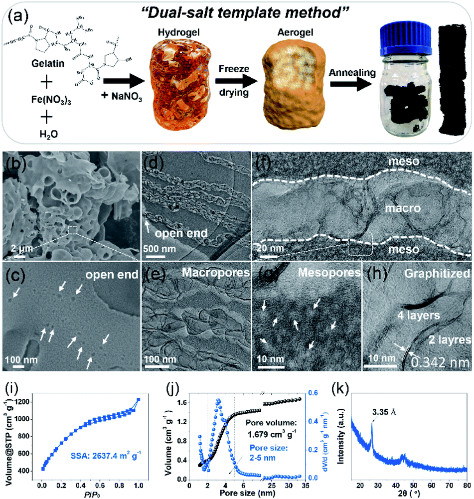
Designing an electrode with a high specific surface area, suitable pore size, and good wettability and conductivity is significant to achieve high-performance SCs.19–21 To create the desired porous structures, templates are usually used.20,21 Especially, the so-called “in situ template catalyst” method can create both hierarchical pores and a high degree of graphitization.20 To this end, a carbon electrode was fabricated via a dual-salt template strategy, as indicated in Fig. 1a. The gelation biomass was melted in hot water and then mixed with Fe(NO3)3 salt to form a homogeneous sol by strong coordination between Fe3+ and the oxygen- and nitrogen-containing functional groups in the gelatin biopolymer.8 After that, a second salt, NaNO3, was added (Fig. S1†). The as-obtained sol was precooled in a refrigerator, followed by liquid nitrogen treatment and freeze-drying. The brown aerogel was further annealed to obtain a bulk monolithic material. The two different salts were uniformly confined in the framework of the biopolymer aerogel. In the annealing process, the NaNO3 salt acts as both the hard template of the macropores and the activation agent of the mesopores, while Fe(NO3)3 functions as a catalyst to further graphitize the amorphous carbon and increase the conductivity.7,8 The morphology of the NMHC electrode was imaged by scanning electron microscopy (SEM) and transmission electron microscopy (TEM) (Fig. 1b–h). It was found that NMHC possesses both rich macropores and mesopores. The macropore channels cross the whole body of NMHC (Fig. 1c and d), whilst the mesopores are distributed on both sides of the macropore channels, forming a unique sandwich-type meso-macro-mesoporous nanostructure (Fig. 1e–g and S2†). The formation of mesopores originated from the etching-expansion effect of the decomposition products of NaNO3, as proved in our previous work.7 The formation of unique macropore channels was investigated by controlling the corresponding salt template. The macroporous holes formed using NaNO3 salt did not connect with each other (Fig. S3a and b†); when Fe(NO3)3 salt was used, several mesopores with graphitized pore walls appeared, but no macropores were formed (Fig. S3c and d†). Therefore, the long macroporous channels may be induced by the vacancies of the NaNO3 salt template, while the migration and penetration of Fe-based particles is driven by the high temperature. Meanwhile, owing to the catalysis of the Fe-based salt, the pore wall was highly graphitized when annealing (Fig. 1h). The texture properties of NMHC were further evaluated by the N2-adsorption experiment. It was shown that NMHC delivered an ultrahigh specific surface area (SSA) of 2637.4 m2 g−1 and a large pore volume of 1.679 cm3 g−1 (Fig. 1i and j); these values were higher than those of the commercial YP50 activated carbon, with a SSA of 1732.9 m2 g−1 and pore volume of 0.73 cm3 g−1 (Fig. S4†). More interestingly, the pore size of NMHC mainly focused on a narrow range of 2–5 nm with a contribution of ∼68%, as calculated from the accumulated volume curve (Fig. 1j). In contrast, YP50 is a typical micropore-dominated carbon, with most of the pore sizes centered around ∼1 nm. Through our design, this highly developed meso-macro-mesoporous structure of NMHC was expected to provide numerous adsorption sites and fast ion-diffusion pathways for the electrolyte compared with the commercial YP50 electrode. Additionally, according to the X-ray diffraction (XRD) results, the sharp peak of NMHC located at 26.8° was detected. Calculated by the Bragg equation (d = nλ/2![[thin space (1/6-em)]](https://www.rsc.org/images/entities/char_2009.gif) sinθ), the interlayer spacing was 3.35 Å, which is an indication of graphitized carbon (Fig. 1k)18 and is consistent with the value (0.342 nm) measured in the HRTEM image by Digital Micrograph software (Fig. 1h). In contrast, large bumps implying amorphous carbon were observed in the XRD pattern of YP50 (Fig. S5†). The Raman spectra also gave typical D (1343 cm−1), G (1592 cm−1), and 2D (2662 cm−1) peaks, which belong to graphitized carbon (Fig. S6†).22 X-ray photoelectron spectroscopy (XPS) was also carried out to identify the dopant elements of the NMHC and YP50 electrodes (Fig. S7 and S8†). The spectra of NMHC revealed that C, N, and O elements accounted for 90.9 at%, 3.9 at%, and 5.2 at%, respectively (Fig. S7a and b†). In the C1s spectrum, C–N (286.0 eV) and C–O (287.2 eV) were fitted (Fig. S7c†). Also, the spectrum of N1s could be deconvolved into three peaks, including pyridinic nitrogen (N-6, 398.5 eV), pyrrolic nitrogen (N-5, 400.3 eV), and graphitic nitrogen (N-Q, 401.5 eV) (Fig. S7d and e†).23 However, for YP50, C (96.96 at%) accounted for the majority of the elemental components, and little O content (3.04 at%) and no N element were detected. The higher heteroatom (N and O) doping content of NMHC could contribute to the higher wettability of the electrolyte. On the basis of our contact angle measurement results, NMHC exhibited a smaller contact angle of 21° with respect to that of non-doped YP50 (48°); the smaller value validated the better wettability according to Young's equation (γsv = γsl + γlvcosθ, where θ is the contact angle) (Fig. S9†). The enhanced wetting ability can be ascribed to the easier adsorption of the ionic liquid molecules on hetero-doped carbon than on non-doped carbon, as proved by DFT calculations.24
sinθ), the interlayer spacing was 3.35 Å, which is an indication of graphitized carbon (Fig. 1k)18 and is consistent with the value (0.342 nm) measured in the HRTEM image by Digital Micrograph software (Fig. 1h). In contrast, large bumps implying amorphous carbon were observed in the XRD pattern of YP50 (Fig. S5†). The Raman spectra also gave typical D (1343 cm−1), G (1592 cm−1), and 2D (2662 cm−1) peaks, which belong to graphitized carbon (Fig. S6†).22 X-ray photoelectron spectroscopy (XPS) was also carried out to identify the dopant elements of the NMHC and YP50 electrodes (Fig. S7 and S8†). The spectra of NMHC revealed that C, N, and O elements accounted for 90.9 at%, 3.9 at%, and 5.2 at%, respectively (Fig. S7a and b†). In the C1s spectrum, C–N (286.0 eV) and C–O (287.2 eV) were fitted (Fig. S7c†). Also, the spectrum of N1s could be deconvolved into three peaks, including pyridinic nitrogen (N-6, 398.5 eV), pyrrolic nitrogen (N-5, 400.3 eV), and graphitic nitrogen (N-Q, 401.5 eV) (Fig. S7d and e†).23 However, for YP50, C (96.96 at%) accounted for the majority of the elemental components, and little O content (3.04 at%) and no N element were detected. The higher heteroatom (N and O) doping content of NMHC could contribute to the higher wettability of the electrolyte. On the basis of our contact angle measurement results, NMHC exhibited a smaller contact angle of 21° with respect to that of non-doped YP50 (48°); the smaller value validated the better wettability according to Young's equation (γsv = γsl + γlvcosθ, where θ is the contact angle) (Fig. S9†). The enhanced wetting ability can be ascribed to the easier adsorption of the ionic liquid molecules on hetero-doped carbon than on non-doped carbon, as proved by DFT calculations.24
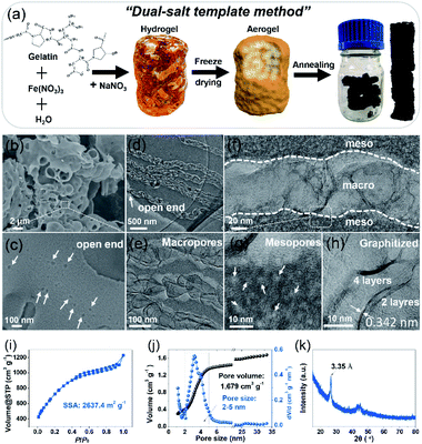 |
| | Fig. 1 (a) The scheme of synthesis of the NMHC electrode via a dual-salt template strategy. (b) SEM image and (c–h) TEM images of the NMHC electrode. (i and j) N2-adsorption results. Left: SSA; right: cumulative pore volume curve and pore size distribution. (k) XRD pattern of NMHC. | |
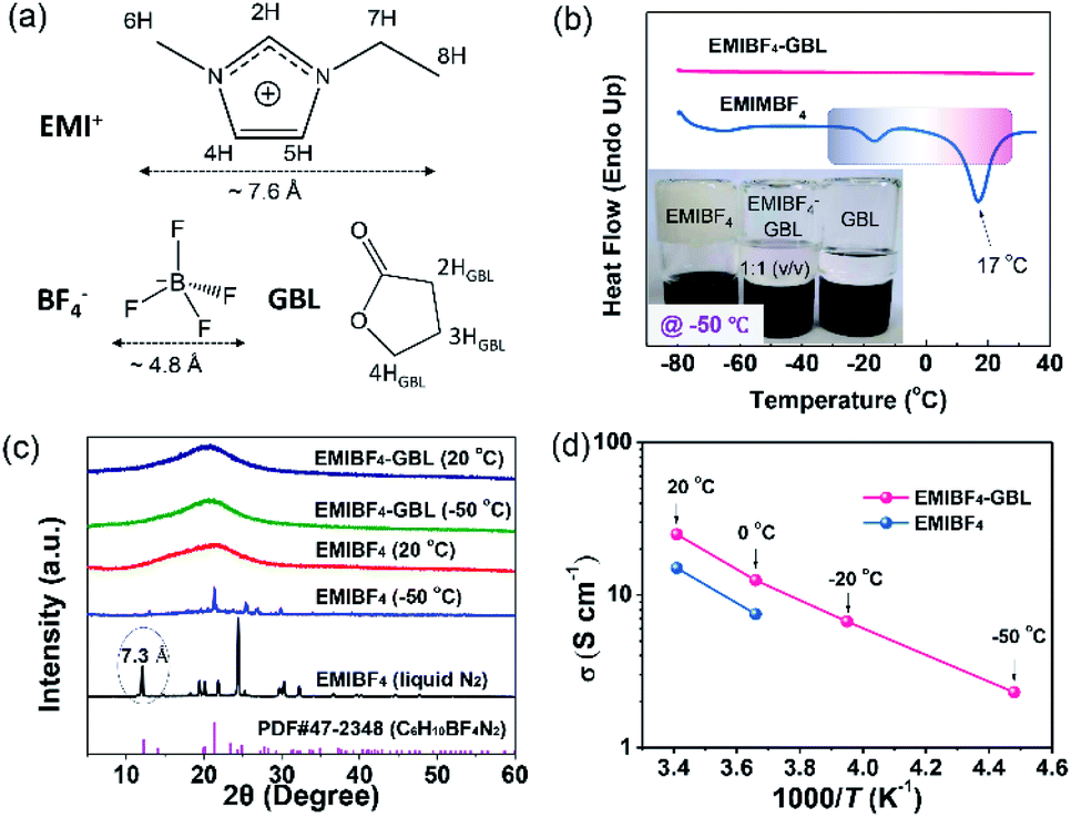
Properties of neat EMIBF4 and EMIBF4–GBL electrolyte
A polar solvent, γ-butyrolactone (GBL), with a low melting point and high boiling point was added to EMIBF4 (Table S1†), a representative imidazolium-based IL with some inherent advantages, such as small ion size (7.6 Å for EMI+ and 4.8 Å for BF4−), low viscosity, explicit H-bond sites, and a high decomposition voltage of up to 4.6 V (Fig. 2a).25–27 As displayed in Fig. 2b, the neat EMIBF4 transformed from a viscous liquid at 20 °C to the solid state at −50 °C. After adding GBL, the mixture remained in the fluidic state, indicating that GBL can effectively prevent the freezing of EMIBF4. The differential scanning calorimetry (DSC) curves showed that the melting point of pure EMIBF4 was around 17 °C and a super-cooling region existed from −35 °C to 17 °C (Fig. 2b), which would create instability in the working conditions of SC.28 However, after the addition of GBL, the exothermic peaks of crystallization disappeared. To verify this liquid–solid phase conversion process, XRD was conducted under different temperatures (Fig. 2c). The XRD pattern of EMIBF4 at 20 °C evinced a large, wide bump due to the disordered phase of the EMIBF4 liquid. When the temperature decreased to −50 °C, partial sharp peaks were observed; these may be due to locally ordered clusters assembled from the EMI+ cations and BF4− anions.29 Further, when EMIBF4 was totally frozen by liquid N2, a peak located at 12.1° was detected. The corresponding interplanar spacing was 7.3 Å, close to the oriented EMI+ size in a hydrogen-bonded zigzag chain along the (001) direction.30 The main peaks of these two XRD patterns partially match the standard JCPDF card (PDF#47-2348 P-phenylenediammonium tetrafluoroborate, C6H10BF4N2), suggesting an evolution of the crystalized states at different temperatures of EMIBF4. The liquid–solid transition of EMIBF4 essentially involves ion disordering, hydrogen bonding, and crystal packing.29 However, in the presence of GBL, EMIBF4–GBL manifested almost identical XRD patterns at 20 °C and −50 °C which were reminiscent of the fluidic state of EMIBF4 at 20 °C. This further corroborates that GBL can fluidize EMIBF4 and thus prevent its freezing even at the rather low temperature of −50 °C. The ion mobilities of neat EMIBF4 and the EMIBF4–GBL IL were surveyed by a conductivity meter and electrochemical impedance spectroscopy (EIS) spectra (Fig. 2d and S10†). At 20 °C, the ionic conductivity (σ) of the neat EMIBF4 IL was measured to be ∼15 S cm−1, which is remarkably lower than that (∼25 S cm−1) of EMIBF4–GBL. With the decrease in temperature from 20 °C to −50 °C, the solution resistance (Rs) of EMIBF4–GBL gradually increased from 1.6 to 17.8 Ω, indicating the abated mobility of the electrolyte ions. The ionic conductivities of the electrolyte at other temperatures were obtained according to the inverse proportion of σ to Rs.31 The EMIBF4–GBL electrolyte maintained a large ionic conductivity of 2.3 S cm−1 at −50 °C. For comparison, the ionic conductivity of the pure EMIBF4 IL plummeted to 7.5 S cm−1 at 0 °C and decreased further due to congealing. Thus, all the consistent data unequivocally substantiate that the introduction of GBL into EMIBF4 promotes its ion mobility at room temperature and presents good anti-freezing properties in deep cold conditions.
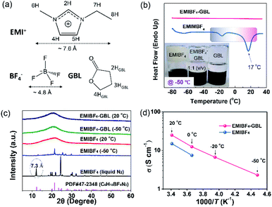 |
| | Fig. 2 Characterization of the EMIBF4–GBL electrolyte. (a) Molecular structure and H sites. (b) The melting point tests of EMIBF4 and EMIBF4–GBL; the inset shows the optical graphs of EMIBF4, EMIBF4–GBL, and GBL under −50 °C. (c) The XRD patterns of neat EMIBF4 and EMIBF4–GBL binary electrolyte under different temperatures. (d) The ion conductivities (σ) of EMIBF4 and the EMIBF4–GBL mixture. | |
The anti-freezing mechanism of binary EMIBF4–GBL electrolyte
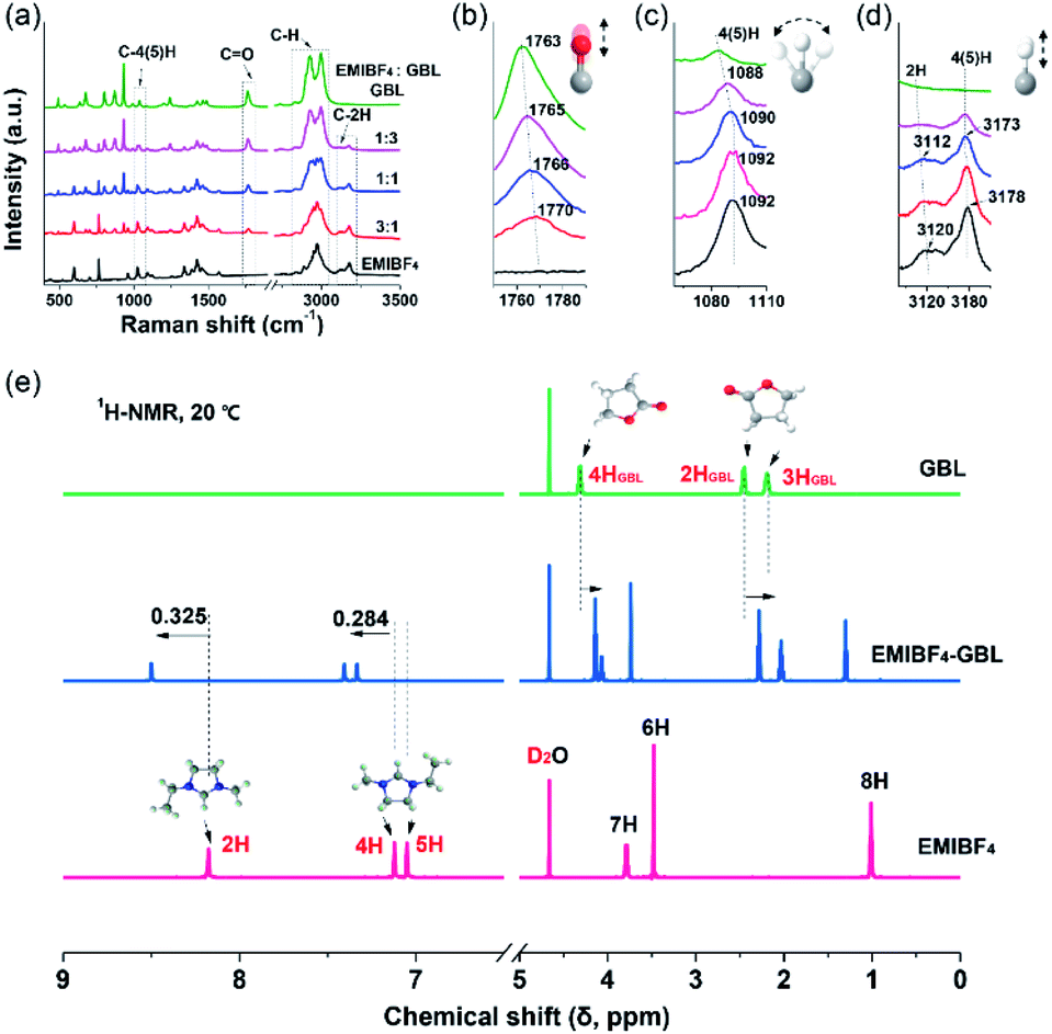
A combination of Raman and nuclear magnetic resonance (NMR) techniques was employed to further determine the origin of the improved ion mobility and the enhanced anti-freezing properties of EMIBF4–GBL. Especially, due to the vibration modes, bonding shifts and intensity changes of the characteristic peaks, Raman spectroscopy is a powerful tool to identify the target sites of the interplay between EMIBF4 and GBL.32Fig. 3a shows the full spectra ranging from 400 to 4000 cm−1 of the EMIBF4–GBL binary system with various volume ratios. The typical Raman shifts near 1750–1790 cm−1 are ascribed to the C![[double bond, length as m-dash]](https://www.rsc.org/images/entities/char_e001.gif) O stretching vibration of GBL (Fig. 3b).33 The peaks at 1070–1110 cm−1 represent the bending vibration of C–4H or C–5H (Fig. 3c), and the signals at 3090–3210 cm−1 stem from the stretching vibrations of C–2H and C–4(5)H on the imidazole ring of the EMI+ cation (Fig. 3d).32,34 The stretching vibrations of other saturated C–H bonds in the EMI+ cation and GBL are located at 2800–3100 cm−1 (Fig. S11†).32 For the CO bond, pure GBL showed a Raman shift of 1763 cm−1; obvious red shifts to 1765, 1766, and 1770 cm−1 accompanied with a reduction in the peak intensity were observed when the amount of EMIBF4 was increased (Fig. 3b). The red shift of the bond in GBL revealed that CO was activated and slightly stretched by interplaying with EMIBF4. Meanwhile, the C–2H, C–4H, and C–5H bonds displayed apparent blue shifts, whereas no shifts occurred in the other saturated C–H bonds (Fig. S11†); this clearly indicates that 2H, 4H, and 5H are the active H sites that can strongly interplay with CO. The Stokes shifts in the Raman spectra denoted the newly minted H-bonds between EMI+ and GBL via ion–dipole interactions (+C–H⋯OC).35
O stretching vibration of GBL (Fig. 3b).33 The peaks at 1070–1110 cm−1 represent the bending vibration of C–4H or C–5H (Fig. 3c), and the signals at 3090–3210 cm−1 stem from the stretching vibrations of C–2H and C–4(5)H on the imidazole ring of the EMI+ cation (Fig. 3d).32,34 The stretching vibrations of other saturated C–H bonds in the EMI+ cation and GBL are located at 2800–3100 cm−1 (Fig. S11†).32 For the CO bond, pure GBL showed a Raman shift of 1763 cm−1; obvious red shifts to 1765, 1766, and 1770 cm−1 accompanied with a reduction in the peak intensity were observed when the amount of EMIBF4 was increased (Fig. 3b). The red shift of the bond in GBL revealed that CO was activated and slightly stretched by interplaying with EMIBF4. Meanwhile, the C–2H, C–4H, and C–5H bonds displayed apparent blue shifts, whereas no shifts occurred in the other saturated C–H bonds (Fig. S11†); this clearly indicates that 2H, 4H, and 5H are the active H sites that can strongly interplay with CO. The Stokes shifts in the Raman spectra denoted the newly minted H-bonds between EMI+ and GBL via ion–dipole interactions (+C–H⋯OC).35
 |
| | Fig. 3 Identification and variation of the H-bond sites. (a) The Raman spectra of EMIBF4–GBL mixtures with various volume ratios. (b) The stretching vibration of the CO bond in GBL. (c) The bending vibration of C–4(5)H of EMI+. (d) The stretching vibrations of C–2H and C–4(5)H bonds in the imidazole ring of EMI+. (e) 1H NMR spectra of 2H, 4H, and 5H in EMIBF4 and EMIBF4–GBL (1:1 by volume) and 1H NMR spectra of 2HGBL, 3HGBL, and 4HGBL in GBL. | |
The chemical states of the H-bonds in neat EMIBF4 and their evolution after adding GBL were further scrutinized by 1H NMR spectra (Fig. 3e). The chemical shift (δ), which results from the magnetic shielding effect of the extra-nuclear electron cloud, is the main index that reflects the chemical environment of the H nucleus.36 A high δ indicates a deficiency of extra-nuclear electrons and a de-shielding effect of H nuclei. The δ values in descending order of neat EMIBF4 were 2H (8.176 ppm), 4H (7.122 ppm), 5H (7.050 ppm), 7H (3.787 ppm), 6H (3.477 ppm), and 8H (1.010 ppm) (Fig. 3e and S12†). 2H emerged in the low field region with the highest chemical shift, clarifying that the 2H site features acidic character.34 This may be due to the electron-withdrawing effect triggered by the H-bond interactions (+C–H⋯F–B−) with F− atoms in BF4− anion, by which 2H, 4H, and 5H possess more positive charges than 6H, 7H, and 8H located outside the imidazole ring (Table S2†).37 The 1H NMR spectrum of neat EMIBF4 validated that the interionic H-bond was mainly derived from +C–2H⋯F–B−, +C–4H⋯F–B−, and +C–5H⋯F–B−. In EMIBF4–GBL, the chemical shifts of 2H, 4H, and 5H further increased to 8.501, 7.406, and 7.334 ppm as a consequence of the large electronegativity of the CO bond of GBL. Noteworthily, the chemical shifts of both 4H and 5H increased by the same value of 0.284 ppm due to their similar chemical environments in the imidazole ring, which was less than the increment (0.325 ppm) of the 2H site (Fig. S13†); this signifies that the interaction between GBL and 2H is more intense, i.e., 2H is the dominant target site of GBL. Meanwhile, in the 1H NMR spectrum of GBL, the H atoms (named 2HGBL, 3HGBL, and 4HGBL) underwent opposite shifts compared with EMI+; therefore, the electrons in EMI+ flowed to the GBL ring (Table S3†). The Raman and 1H NMR spectra provide hard evidence that GBL significantly affected the interionic H-bonding between EMI+ and BF4− targeted on 2H, 4H, and 5H.
Density functional theory (DFT) simulations were carried out in order to further expound the detailed mechanism of the bonding among EMI+, BF4− and GBL. Two different binding configurations on the bilateral sides of EMI+ were considered (Fig. 4a and Table S4).† The most energetically stable EMI–BF4 system revealed that 4H and 5H are favourable sites to form interionic H-bonds, with a binding energy of −21.11 kJ mol−1. One H-bond length (termed r5H–F) is 1.982 Å, and the other one (r4H–F) is 2.128 Å. For the secondarily stable BF4–EMI system, 2H was the active site; however, only one H-bond formed. The bond length between F and H atom (r2H–F) is 2.027 Å. In contrast to the BF4–EMI system, 2H was the most favourable binding site in the energetically favourable GBL–EMI system, with a binding strength of −9.68 kJ mol−1. The H-bond length between O and 2H atom (r2H–O) was the shortest (1.919 Å) among all the configurations; this indicates that 2H is the main targeting site that GBL prefers to interact with (or attack). The electrostatic potential graphs also illustrated that the carbonyl O atom in the GBL–EMI system gained 0.065e− compared with neat GBL, fitting well with the 1H NMR results (Fig. S14e and S15†). Taking into account the co-existence of EMI+, BF4−, and GBL, the practical ternary system was assessed. In this case, GBL–EMI–BF4 (−13.99 kJ mol−1) was more favorable than BF4–EMI–GBL (−11.83 kJ mol−1). We could observe that 2H was the binding site of GBL and EMI+. Additionally, the bond length of CO (rCO) stretched from 1.210 to 1.217 Å (Fig. S15 and Fig. S16†), which was in accordance with the Raman shift of the CO stretching vibration. The carbonyl O atom gained 0.046e− from EMI+ (Fig. S14c†). However, after the interaction of EMI+ with GBL, only one H-bond (+C–5H⋯F–B−) between EMI+ and BF4− remained, and it was noticeably weakened; r5H–F was lengthened from the original 1.982 Å in the EMI–BF4 system to 2.006 Å, while the other H-bond (+C–4H⋯F–B−) totally vanished. The above theoretical calculation data reveal that the interionic H-bond formation in EMIBF4 is inhibited through intense interactions with GBL at the 2H site, which is highly consistent with the Raman and 1H NMR spectroscopy results.
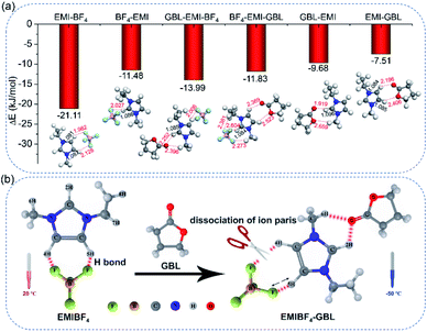 |
| | Fig. 4 The mechanism of H-bond disruption. (a) The adsorption energies of the most favorable configurations: EMI–BF4, GBL–EMI–BF4, GBL–EMI, and the secondarily favorable configurations: BF4–EMI, BF4–EMI–GBL, EMI–GBL. In all the configurations, 2H, 4H, and 5H were the target sites of the bonding, which is consistent with the experimental observations. The inset shows the lengths of the H-bonds (red dashed line) and C–H bonds (black solid lines). (b) The scheme of H-bond breaking/weakening and the dissociation of the EMI–BF4 ion pairs after adding GBL. | |
Based on the results of Raman, 1H NMR, and DFT studies, the H-bond breaking mechanism is depicted in Fig. 4b. GBL interacts with 2H, concomitant with the weakening of +C–5H⋯F–B− and the cleavage of +C–4H⋯F–B−. For the neat EMIBF4, the H-bond can foster localized electrostatic coupling (as indicated by the bump in the XRD pattern). When the operational temperature dropped below the melting point of EMIBF4, the associated ion pairs arranged into an orderly quasi-crystal network (as indicated by the sharp peak in the XRD pattern). For EMIBF4–GBL, the intense ion–dipole interactions between EMI+ and GBL can effectively break/weaken the interionic H-bonds in EMIBF4 to facilitate the separation of EMI+ and BF4− ions, forming isolated ions or newly solvated couples (GBL–EMI). Therefore, the ion-mobility/conductivity was appreciably enhanced and the viscosity was substantially decreased. Moreover, due to the breaking of the degree of order of EMI+ and BF4−, crystallization at low temperature is more difficult, thus preventing EMIBF4 from freezing.
Kinetics of NMHC and YP50 electrodes in EMIBF4–GBL electrolyte
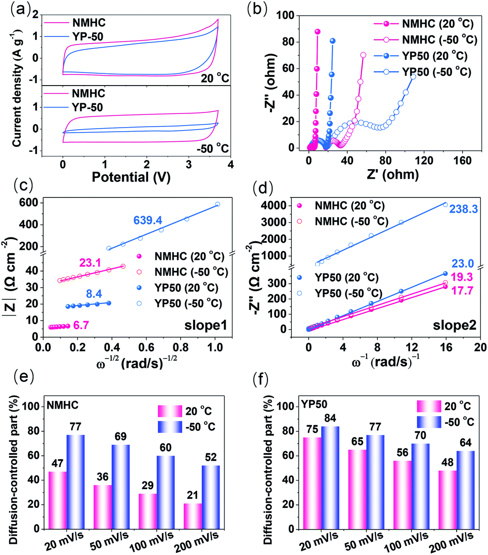
The fast kinetics of the NMHC electrode in EMIBF4–GBL electrolyte was demonstrated by using the commercial YP50 electrode as the control sample. Benefiting from the large SSA with a high proportion of ion-available mesopores, NMHC apparently stored more charges than YP50, as indicated by the areas of the CV curves at both 20 °C and −50 °C (Fig. 5a). Moreover, the rectangular shape changed little for NMHC but shrank dramatically for YP50, which suggests that NMHC has a higher rate capability than YP50. The fast kinetics (electron transfer and ion diffusion) of NMHC was further investigated by EIS experiments and current response fitting. The similar Rs dependence on temperature in these two electrodes validated that the intrinsic properties of the EMIBF4–GBL electrolyte were not significantly affected by the electrodes. However, the charge transfer resistance (Rct) of NMHC inferred from the semi-circles was much lower than that of the YP50 electrode (Fig. 5b and Table S5†). The lower Rct of NMHC can be largely attributed to the graphitization of NMHC and, thus, the enhanced electron transfer. The diffusion coefficient (Da) of the electrolyte ions was further estimated by impedance data at lower frequencies (ΔZim/ΔZre ∼1), i.e., the Warburg region, to clarify the faster ion diffusion of NMHC. In this frequency range, the magnitude of the impedance varies linearly with (ω)−1/2 according to the following equation:38,39where CL and L are the low-frequency redox capacitance and film thickness of the electrode material, respectively. ω is the radian frequency, and ω = 2πf. The value of CL can be obtained from the plot of ΔZimvs. 1/ω, which is linear with a slope of 1/CL.
 |
| | Fig. 5 (a) CV curves and (b) EIS spectra of NMHC and YP50 electrode at 20 °C and −50 °C, respectively. (c) |Z|–(ω)−1/2, and (d) (−Z′′)–ω plots based on the EIS data. (e and f) The proportions of diffusion-controlled current of the CV curves of the NMHC and YP50 electrodes at different current densities from 20 to 200 mV s−1. | |
Therefore, the diffusion coefficient can be obtained as follows:
| | | Da = (L × slope 2/slope 1)2 | (5) |
It can be seen that Da is largely associated with the thickness of the electrode L, but one should note that Da is not positively related to L because L also affects the whole Warburg region (as a semi-quantitative analysis, here, L was normalized to be 1 μm for all the samples. Note: L can be accurately obtained by measuring the cross-section through SEM). The Z–(ω)−1/2 and (−Zim)–(1/ω) dependence were plotted to obtain slope 1 and slope 2, as depicted in Fig. 5c and d. According to eqn (5), Da was calculated to be 7.0 × 10⁻⁸ and 7.0 × 10⁻⁹ cm−2 s−1 for NMHC and 7.5 × 10⁻⁸ and 1.4 × 10⁻⁹ cm−2 s−1 for YP50 electrode at 20 °C and −50 °C, respectively. These results indicate that lowering the temperature retarded the ion diffusion in both the NMHC and YP50 electrodes. The Da values of NMHC and YP50 were similar at 20 °C; however, Da of NMHC obviously sustained a greater decline than YP50 from 20 °C to −50 °C. These results further proved the better ion diffusion behavior of NMHC than of YP50 when used at a low temperature.
The in-depth analysis of the ion-diffusion kinetics was characterized by the current responses (i) of the CV curves at different scan rates (v) on the basis of the relationship in eqn (6):40–42
where
k1v is the capacitive current and
k2v1/2 is the diffusion-controlled current. A larger proportion of the capacitive current usually implies better rate capability. To distinguish the proportions of the diffusion-controlled current and capacitive current, a linear fitting of the voltammetric currents at each potential within the voltage window was conducted to obtain the coefficients
k1 and
k2 based on
eqn (7):
| | | i(V)/v1/2 = k1v1/2 + k2 | (7) |
The results showed that lowering the temperature increased the ion-diffusion contribution significantly, which is in line with the calculated Da and the change of Rs with temperature (Fig. S9†). The larger diffusion-controlled current at lower temperatures for both samples is due to the sluggish ion diffusion of the electrolyte ions; this is an intrinsic factor caused by the temperature, as revealed in Fig. 1d. In detail, the diffusion-controlled current of the NMHC electrode accounted for 47% and 21% of the current at 20 °C at scan rates of 20 mV s−1 and 200 mV s−1, respectively; these increased to 77% and 52% at −50 °C, respectively (Fig. 5e and S17†). However, even at 20 °C, YP50 exhibited considerable diffusion-controlled currents of 75% and 48% at 20 mV s−1 and 200 mV s−1, respectively, which further increased to 84% and 64% at −50 °C (Fig. 5f and S18†). These results confirm that the mesopores of NMHC distinctly prevailed over the micropores of YP50. The larger mesopores in NMHC enabled more rapid ion diffusion than the micropores at low temperature. To conclude, NMHC revealed faster kinetics with both rapid electron transfer and ion diffusion than YP50 at −50 °C; this was further demonstrated by the inferior performance of YP50 with respect to NMHC (Fig. S19†). For example, even at a low current density of 0.5 A g−1, YP50 only showed a specific capacitance of 12 F g−1 at −50 °C, which was far lower than that of NMHC (128 F g−1).
Synergy of the NMHC electrode and EMIBF4–GBL electrolyte for low-temperature SCs
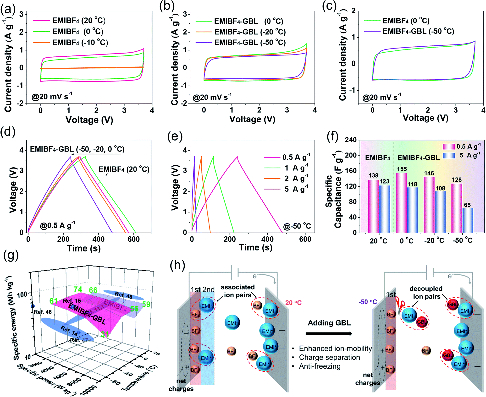
The fast kinetics of NMHC under EMIBF4–GBL proved it to be a promisingly compatible electrode for high energy–power density SCs at low temperatures. However, the synergy by which the EMIBF4–GBL electrolyte promoted the low-temperature performance of the NMHC electrode required further elucidation. In this regard, cyclic voltammetry (CV) curves using both EMIBF4 and EMIBF4–GBL were recorded at 20 °C (Fig. S20†). The quantified charges from the CV curves showed that the charge (QEMIBF4–GBL) using EMIBF4–GBL was 0.296 C, surpassing that of QEMIBF4 (0.277 C) using neat EMIBF4; this indicates the reinforced ion storage capability of EMIBF4–GBL. Meanwhile, a higher polarization current was noted in EMIBF4–GBL; side reactions may occur in GBL–EMI couples because GBL has a higher HOMO level (−6.241 eV) than individual EMI+ (−8.652 eV) in EMIBF4,43,44 which indicates that GBL may gain electrons from the electrode interface prior to EMI+ adsorption (Fig. S21†).45 To avoid possible side reactions, the CV curves operated in the applicable temperature range were evaluated. For EMIBF4, as the temperature decreased, the CV curves showed apparent shrinkage from 20 °C to 0 °C and severe polarization at −10 °C due to malfunctioning of the cell (Fig. 6a and S22†). For EMIBF4–GBL, the CV curves retained good rectangular shapes as the temperature declined from 0 °C to −50 °C. The calculated capacities were 0.266, 0.247, and 0.217 C at 0 °C, −20 °C, and −50 °C, respectively, compared with that (0.277 C) at 20 °C in neat EMIBF4; this demonstrates excellent capacity retention (Fig. 6b and S23†). Moreover, the capacity at −50 °C was even slightly larger than that (0.213 C) obtained using EMIBF4 at 0 °C (Fig. 6c). The much better low-temperature performance using EMIBF4–GBL was further identified by charge–discharge (CD) tests. It was found that a longer discharge time was achieved by EMIBF4–GBL at 0 °C than by EMIBF4 at 20 °C (Fig. 6d and S24†). Additionally, EMIBF4–GBL could allow SCs to run smoothly at high rates from 0.5 to 5 A g−1 in cold conditions (Fig. 6e and S25†). As summarized in Fig. 6f, a capacitance of 155 F g−1 was attained when EMIBF4–GBL was used at 0.5 A g−1 and 0 °C, exceeding that in EMIBF4 electrolyte at 20 °C (138 F g−1). When operated at the large current density of 5 A g−1, EMIBF4–GBL still retained excellent capacitance at 0 °C (118 F g−1) and −20 °C (108 F g−1) and showed satisfactory performance at −50 °C (65 F g−1). Under these extreme conditions, the stable capacitance persisted over 6000 CD cycles with only 0.0012% decay per cycle, together with a high coulombic efficiency of 99.8% (Fig. S26†). The energy–power–temperature diagram revealed a large specific energy of 61 W h kg−1 at −50 °C and 925 W kg−1, which ranks high compared with the reported literature (Fig. 6g and Table S6†).11,12,14,15,46–48
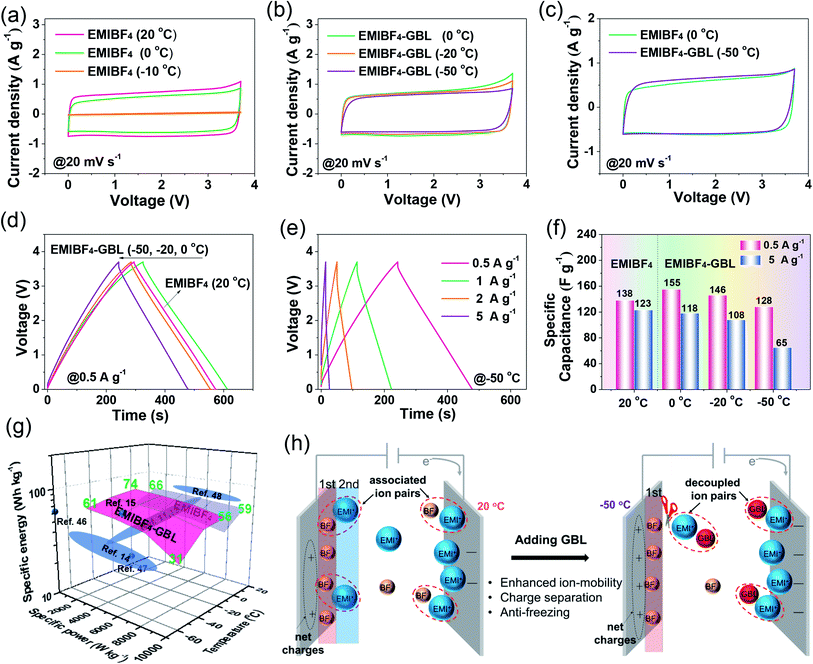 |
| | Fig. 6 Low-temperature performance of NMHC based on EMIBF4–GBL electrolyte. (a and b) CV curves using EMIBF4 and EMIBF4–GBL as the electrolyte at 20 mV s−1 and different temperatures. (c) Comparison of the CV curves at 0 °C and −50 °C using EMIBF4 and EMIBF4–GBL. (d) CD curves at different temperatures varying from 20 °C to −50 °C. (e) CD curves using EMIBF4–GBL as the electrolyte at different current densities operated at −50 °C. (f) The calculated specific capacitances at different temperatures at the current densities of 0.5 and 5 A g−1, respectively. (g) Diagram of the energy–power–temperature dependence based on a two-electrode symmetric coin cell and comparison with the reported literature (the red shaded area is the performance using EMIBF4–GBL electrolyte). (h) The role of GBL, showing that GBL can promote the charge separation and inhibit the freezing of EMIBF4via cutting off the H-bond connections of the associated ion pairs. | |
On the basis of the anti-freezing feature of the EMIBF4–GBL electrolyte and the experimental performance of the NMHC electrode, the synergistic effect of the electrode–electrolyte combination was summarized. In terms of the electrode, the NMHC electrode ensured abundant ion-accessible sites for the adsorption of electrolyte ions. Meanwhile, 2–5 nm mesopores provided unimpeded nano-highways for ion diffusion, and the partial graphitization promoted the rapid electron transfer, showing explicitly faster kinetics than the commercial YP50 electrode. In terms of the electrolyte, the intense association of EMI+ and BF4− in neat EMIBF4 caused large resistance of the ion transport. The charges of the adsorbed electrolyte ions on the first layer at the interface were offset by the opposite charges of the counter ions in the second layer. The so-called ‘overscreening effect’ was detrimental to the net charge stored at the electrode interface, thus lowering the capacitance.49,50 GBL played a role in breaking/weakening the H-bond connections of the ion couples in the EMIBF4 ILs (Fig. 6h). The EMI+ cations interplayed with GBL instead of only BF4−. As the carriers of opposite charges, EMI+ and BF4− were separated. The weakening of the ‘overscreening effect’ created more net charges at the electrode interface.27 Additionally, benefiting from the interaction of EMI+ and GBL, the isolated ions could diffuse more freely at −50 °C. Contributed by both the NMHC electrode and EMIBF4–GBL electrolyte, an SC with high energy and high power density at the ultralow temperature of −50 °C was obtained.
3. Conclusions
To conclude, this work presented synergy between an electrode and electrolyte to enhance the performance of IL-based SCs operated at low temperature. Specifically, a mesopore-dominated carbon electrode with a large SSA (2637.4 m2 g−1) and pore volume (1.679 cm3 g−1), appropriate pore size distribution (2–5 nm), partial graphitization, and good wettability designed by a dual-salt template method showed much better kinetics (ion-diffusion and electron-transfer) in the anti-freezing EMIBF4–GBL electrolyte than commercial micropore-dominated YP50 carbon. Meanwhile, the anti-freezing mechanism of the EMIBF4–GBL electrolyte was investigated by Raman spectroscopy, 1H NMR spectroscopy and DFT calculations. The perspective from H-bond chemistry showed that the CO bonds in GBL intensely interact with the 2H sites on the imidazolium rings; this breaks the interionic H-bonds of EMIBF4 at the 4H sites and weakens the H-bonds at the 5H sites, thus enabling good ion mobility (2.3 S cm−1) and anti-freezing properties at −50 °C. This “H-bond breakage” behavior of the EMIBF4 IL positively affected the SC performance of the NMHC electrode under deep cold conditions, thus delivering superior specific energies of 61 W h kg−1 at a specific power of 925 W kg−1 and 31 W h kg−1 at 9250 W kg−1 in a symmetric coin cell at −50 °C.
Conflicts of interest
There are no conflicts to declare.
Acknowledgements
This work was supported by the National Natural Science Foundation of China (21506111). The authors also gratefully acknowledge the help of Z. Z. Ye, J. Wang, Z. F. Yang, and K. Chao. The author Jing Li thanks for the financial support from China Scholarship Council (CSC, File No. 201806240341)
Notes and references
- Y. Shi, L. Peng, Y. Ding, Y. Zhao and G. Yu, Chem. Soc. Rev., 2015, 44, 6684–6696 RSC.
- P. Simon and Y. Gogotsi, Nat. Mater., 2008, 7, 845–854 CrossRef CAS PubMed.
- Q. Dou, L. Liu, B. Yang, J. Lang and X. Yan, Nat. Commun., 2017, 8, 2188 CrossRef PubMed.
- K. Raju, H. Han, D. B. Velusamy, Q. Jiang, H. Yang, F. P. Nkosi, N. Palaniyandy, K. Makgopa, Z. Bo and K. I. Ozoemena, ACS Energy Lett., 2020, 5, 23–30 CrossRef CAS.
- M. Yu, D. Lin, H. Feng, Y. Zeng, Y. Tong and X. Lu, Angew. Chem. Int. Ed., 2017, 56, 5454–5459 CrossRef CAS PubMed.
- J. Li, M. Wei, W. Chu and N. Wang, Chem. Eng. J., 2017, 316, 277–287 CrossRef CAS.
- J. Li, N. Wang, J. Tian, W. Qian and W. Chu, Adv. Funct. Mater., 2018, 28, 1806153 CrossRef.
- J. Li, N. Wang, J. Deng, W. Qian and W. Chu, J. Mater. Chem. A, 2018, 6, 13012–13020 RSC.
- C. Largeot, C. Portet, J. Chmiola, P.-L. Taberna, Y. Gogotsi and P. Simon, J. Am. Chem. Soc., 2008, 130, 2730–2731 CrossRef CAS PubMed.
- W. Xu and C. A. Angell, Science, 2003, 302, 422–425 CrossRef CAS PubMed.
- W.-Y. Tsai, R. Lin, S. Murali, L. Li Zhang, J. K. McDonough, R. S. Ruoff, P.-L. Taberna, Y. Gogotsi and P. Simon, Nano Energy, 2013, 2, 403–411 CrossRef CAS.
- R. Lin, P.-L. Taberna, S. Fantini, V. Presser, C. R. Pérez, F. Malbosc, N. L. Rupesinghe, K. B. K. Teo, Y. Gogotsi and P. Simon, J. Phys. Chem. Lett., 2011, 2, 2396–2401 CrossRef CAS.
- K. E. Gunderson-Briggs, T. Rüther, A. S. Best, M. Kar, C. Forsyth, E. I. Izgorodiana, D. R. MacFarlane and A. F. Hollenkamp, Angew. Chem. Int. Ed., 2019, 58, 4390–4394 CrossRef CAS PubMed.
- J. Xu, N. Yuan, J. M. Razal, Y. Zheng, X. Zhou, J. Ding, K. Cho, S. Ge, R. Zhang, Y. Gogotsi and R. H. Baughman, Energy Storage Mater., 2019, 22, 323–329 CrossRef.
- J. Lang, X. Zhang, L. Liu, B. Yang, J. Yang and X. Yan, J. Power Sources, 2019, 423, 271–279 CrossRef CAS.
- Q. Nian, J. Wang, S. Liu, T. Sun, S. Zheng, Y. Zhang, Z. Tao and J. Chen, Angew. Chem. Int. Ed., 2019, 58, 16994–16999 CrossRef CAS PubMed.
- E. Perricone, M. Chamas, L. Cointeaux, J. C. Leprêtre, P. Judeinstein, P. Azais, F. Béguin and F. Alloin, Electrochim. Acta, 2013, 93, 1–7 CrossRef CAS.
- A. Senda, K. Matsumoto, T. Nohira and R. Hagiwara, J. Power Sources, 2010, 195, 4414–4417 CrossRef CAS.
- X. Hu, X. Sun, S. J. Yoo, B. Evanko, F. Fan, S. Cai, C. Zheng, W. Hu and G. D. Stucky, Nano Energy, 2019, 56, 828–839 CrossRef CAS.
- Y. Lin, Z. Chen, C. Yu and W. Zhong, Electrochim. Acta, 2020, 334 Search PubMed.
- F. Zhang, T. Liu, M. Li, M. Yu, Y. Luo, Y. Tong and Y. Li, Nano Lett., 2017, 17, 3097–3104 CrossRef CAS PubMed.
- C. Cui, W. Qian, Y. Yu, C. Kong, B. Yu, L. Xiang and F. Wei, J. Am. Chem. Soc., 2014, 136, 2256–2259 CrossRef CAS PubMed.
- T. Q. Lin, I. W. Chen, F. X. Liu, C. Y. Yang, H. Bi, F. F. Xu and F. Q. Huang, Science, 2015, 350, 1508–1513 CrossRef CAS PubMed.
- Z. Pan, H. Zhi, Y. Qiu, J. Yang, L. Xing, Q. Zhang, X. Ding, X. Wang, G. Xu, H. Yuan, M. Chen, W. Li, Y. Yao, N. Motta, M. Liu and Y. Zhang, Nano Energy, 2018, 46, 266–276 CrossRef CAS.
- J. Chmiola, C. Largeot, P.-L. Taberna, P. Simon and Y. Gogotsi, Angew. Chem. Int. Ed., 2008, 47, 3392–3395 CrossRef CAS PubMed.
-
M. Lu, Supercapacitors: materials, systems, and applications, John Wiley & Sons, 2013 Search PubMed.
- Y. Xu, Z. Lin, X. Zhong, X. Huang, N. O. Weiss, Y. Huang and X. Duan, Nat. Commun., 2014, 5, 4554 CrossRef CAS PubMed.
- J. R. Tian, C. J. Cui, Q. Xie, W. Z. Qian, C. Xue, Y. H. Miao, Y. Jin, G. Zhang and B. H. Guo, J. Mater. Chem. A, 2018, 6, 3593–3601 RSC.
- A. R. Choudhury, N. Winterton, A. Steiner, A. I. Cooper and K. A. Johnson, J. Am. Chem. Soc., 2005, 127, 16792–16793 CrossRef CAS PubMed.
- J. D. Holbrey, W. M. Reichert, M. Nieuwenhuyzen, O. Sheppard, C. Hardacre and R. D. Rogers, Chem. Commun., 2003, 476–477 RSC.
- X. Dong, Z. Guo, Z. Guo, Y. Wang and Y. Xia, Joule, 2018, 2, 902–913 CrossRef CAS.
- R. W. Berg, M. Deetlefs, K. R. Seddon, I. Shim and J. M. Thompson, J. Phys. Chem. B, 2005, 109, 19018–19025 CrossRef CAS PubMed.
- T. Munshi, V. L. Brewster, H. G. M. Edwards, M. D. Hargreaves, S. K. Jilani and I. J. Scowen, Drug Test. Anal., 2013, 5, 678–682 CrossRef CAS PubMed.
- S. A. Katsyuba, M. V. Vener, E. E. Zvereva, Z. Fei, R. Scopelliti, G. Laurenczy, N. Yan, E. Paunescu and P. J. Dyson, J. Phys. Chem. B, 2013, 117, 9094–9105 CrossRef CAS PubMed.
- H. K. Kashyap and R. Biswas, J. Phys. Chem. B, 2010, 114, 254–268 CrossRef CAS PubMed.
- A. C. Forse, J. M. Griffin, C. Merlet, P. M. Bayley, H. Wang, P. Simon and C. P. Grey, J. Am. Chem. Soc., 2015, 137, 7231–7242 CrossRef CAS PubMed.
- K. Fumino, A. Wulf and R. Ludwig, Angew. Chem. Int. Ed., 2008, 47, 3830–3834 CrossRef CAS PubMed.
- P. Ahuja, V. Sahu, S. K. Ujjain, R. K. Sharma and G. Singh, Electrochim. Acta, 2014, 146, 429–436 CrossRef CAS.
- S. K. Ujjain, P. Ahuja and R. K. Sharma, J. Mater. Chem. A, 2015, 3, 9925–9931 RSC.
- T. Brezesinski, J. Wang, J. Polleux, B. Dunn and S. H. Tolbert, J. Am. Chem. Soc., 2009, 131, 1802–1809 CrossRef CAS PubMed.
- Z. Li, S. Gadipelli, H. Li, C. A. Howard, D. J. L. Brett, P. R. Shearing, Z. Guo, I. P. Parkin and F. Li, Nat. Energy, 2020, 5, 160–168 CrossRef CAS.
- L. Liu, J. Lang, P. Zhang, B. Hu and X. Yan, ACS Appl. Mater. Interfaces, 2016, 8, 9335–9344 CrossRef CAS PubMed.
- S. P. Ong, O. Andreussi, Y. Wu, N. Marzari and G. Ceder, Chem. Mater., 2011, 23, 2979–2986 CrossRef CAS.
- N. Shao, X.-G. Sun, S. Dai and D.-e. Jiang, J. Phys. Chem. B, 2012, 116, 3235–3238 CrossRef CAS PubMed.
- S. Zhang, Z. Bo, H. Yang, J. Yang, L. Duan, J. Yan and K. Cen, J. Power Sources, 2016, 334, 162–169 CrossRef CAS.
- J. Tian, C. Cui, Q. Xie, W. Qian, C. Xue, Y. Miao, Y. Jin, G. Zhang and B. Guo, J. Mater. Chem. A, 2018, 6, 3593–3601 RSC.
- A. Tatlisu, Z. Huang and R. Chen, ChemSusChem, 2018, 11, 3899–3904 CrossRef CAS PubMed.
- Y. Zhu, S. Murali, M. D. Stoller, K. J. Ganesh, W. Cai, P. J. Ferreira, A. Pirkle, R. M. Wallace, K. A. Cychosz, M. Thommes, D. Su, E. A. Stach and R. S. Ruoff, Science, 2011, 332, 1537–1541 CrossRef CAS PubMed.
- H. Wang, A. C. Forse, J. M. Griffin, N. M. Trease, L. Trognko, P.-L. Taberna, P. Simon and C. P. Grey, J. Am. Chem. Soc., 2013, 135, 18968–18980 CrossRef CAS PubMed.
- M. V. Fedorov and A. A. Kornyshev, Chem. Rev., 2014, 114, 2978–3036 CrossRef CAS PubMed.
Footnotes |
| † Electronic supplementary information (ESI) available. See DOI: 10.1039/d0ta02677h |
| ‡ These authors contributed equally to this work. |
|
| This journal is © The Royal Society of Chemistry 2020 |
Click here to see how this site uses Cookies. View our privacy policy here. 
 Open Access Article
 This Open Access Article is licensed under a Creative Commons Attribution-Non Commercial 3.0 Unported Licence
 *cd,
Weizhong
Qian
b and
Wei
Chu
*cd,
Weizhong
Qian
b and
Wei
Chu