Ultrahigh discharge efficiency and improved energy density in rationally designed bilayer polyetherimide–BaTiO3/P(VDF-HFP) composites†
Liang
Sun
a,
Zhicheng
Shi
 *a,
Huanlei
Wang
a,
Kun
Zhang
*b,
Davoud
Dastan
c,
Kai
Sun
d and
Runhua
Fan
d
aSchool of Materials Science and Engineering, Ocean University of China, Qingdao 266100, P. R. China. E-mail: zcshi@ouc.edu.cn
bKey Laboratory of Microgravity (National Microgravity Laboratory), Institute of Mechanics, Chinese Academy of Sciences, Beijing 100190, China. E-mail: zhangkun@imech.ac.cn
cSchool of Materials Science and Engineering, Georgia Institute of Technology, Atlanta, Georgia-30332, USA
dInstitute of Marine Materials Science and Engineering, Shanghai Maritime University, Shanghai 201306, P. R. China
First published on 2nd March 2020
Abstract
Polymer dielectric composites are of great interest as film capacitors that are widely used in pulsed power systems. For a long time, huge efforts have been devoted to achieving energy densities as high as possible to satisfy the miniaturization and high integration of electronic devices. However, the discharge efficiency which is particularly crucial to practical applications has gained little attention. With the target of achieving concurrently improved energy density and efficiency, a class of rationally designed bilayer composites consisting of a pure polyetherimide layer and a BaTiO3/P(VDF-HFP) composite layer were prepared. Interestingly, the bilayer composites exhibit ultrahigh discharge efficiencies η (>95%) under external electric fields up to 400 kV mm−1 which are much higher than most of the so far reported results (η < 80%). Meanwhile, a low loss (tan![[thin space (1/6-em)]](https://www.rsc.org/images/entities/char_2009.gif) δ < 0.05 @ 10 kHz) comparable to that of the pure polyetherimide is obtained. In addition, the bilayer composites show impressive improvements in breakdown strengths Eb, i.e., 285%, 363%, 366% and 567% for composites with 5 vol%, 10 vol%, 20 vol% and 40 vol% BaTiO3, compared to their single layer counterparts, resulting in obviously improved energy densities Ud. In particular, the bilayer composite with 10 vol% BaTiO3 displays the most prominent comprehensive energy storage performance, i.e., η ∼ 96.8% @ 450 kV mm−1, Ud ∼ 6 J cm−3 @ 450 kV mm−1, tan
δ < 0.05 @ 10 kHz) comparable to that of the pure polyetherimide is obtained. In addition, the bilayer composites show impressive improvements in breakdown strengths Eb, i.e., 285%, 363%, 366% and 567% for composites with 5 vol%, 10 vol%, 20 vol% and 40 vol% BaTiO3, compared to their single layer counterparts, resulting in obviously improved energy densities Ud. In particular, the bilayer composite with 10 vol% BaTiO3 displays the most prominent comprehensive energy storage performance, i.e., η ∼ 96.8% @ 450 kV mm−1, Ud ∼ 6 J cm−3 @ 450 kV mm−1, tan![[thin space (1/6-em)]](https://www.rsc.org/images/entities/char_2009.gif) δ ∼ 0.025 @ 10 kHz, and Eb ∼ 483.18 kV mm−1. The ultrahigh discharge efficiencies and high energy densities, along with low loss and breakdown strengths, make these bilayer composites ideal candidates for high-performance dielectric energy-storage capacitors.
δ ∼ 0.025 @ 10 kHz, and Eb ∼ 483.18 kV mm−1. The ultrahigh discharge efficiencies and high energy densities, along with low loss and breakdown strengths, make these bilayer composites ideal candidates for high-performance dielectric energy-storage capacitors.
1. Introduction
Polymer film capacitors (PFCs) have drawn considerable attention in recent years owing to their superior charge–discharge capabilities, outstanding cycling stabilities, excellent self-healing capability and wide application in hybrid electric vehicles, medical defibrillators, electromagnetic launch systems, etc.1–4 However, the applications of PFCs are greatly restricted by their low energy densities. In principle, the energy density (Ud) of a dielectric material can be expressed by the equations Ud = 1/2ε0εrE2 for a linear dielectric material and Ud = ∫EdD for a nonlinear dielectric material, where ε0 and εr represent the dielectric permittivities of the vacuum and dielectrics, E is the applied electric field which should be lower than the breakdown strength (Eb) of the materials, and D = ε0εrE is the electric displacement. Accordingly, high εr and high Eb are desired for high Ud. To achieve this, various strategies have been proposed, among which constructing polymer based composites filled with high εr or high Eb fillers has been demonstrated to be effective.5–7 To obtain improved εr, ferroelectric ceramic fillers (e.g., BaTiO3,8,9 SrTiO3,10 NaNbO3,11etc.) and conductors (e.g., metals,12–14 carbon nanotubes,15 graphene,16,17 conductive polymers,18etc.) are usually employed. However, improved εr is always accompanied by suppressed Eb, deteriorated η and elevated loss.19 To achieve improved Eb, fillers with high Eb (e.g., boron nitride, alumina, silica, etc.) are usually employed.1,2 Unfortunately, the fillers with high Eb often exhibit low εr, leading to suppressed εr.20 As a result, a reasonable balance between εr and Eb has been a problem demanding a prompt solution until now. Although various innovative strategies, such as designing core–shell structured fillers21,22 and surface modification of fillers,23–25 have been proposed to address this dilemma, the effect is still not satisfactory.Recently, researchers found that multilayer structured composites may offer a feasible paradigm to realize the concurrent improvement of εr and Eb.26–29 Compared with single-layer composites, multilayer composites possess another type of mesoscopic interface between adjacent layers, in addition to the microscopic interfaces between the filler and matrix, which may induce strong interfacial polarization and extra charge storage.30–32 Wang and co-workers reported the design of trilayered films consisting of stacked barium titanate/poly(vinylidene fluoride-co-hexafluoropropylene) (BaTiO3/P(VDF-HFP)) nanocomposite layers, where the middle layer with a high BaTiO3 content offered high εr while the two outer layers with a low BaTiO3 content provided high Eb. A significantly improved Eb of ∼526 kV mm−1 and a moderately enhanced εr of ∼12 @ 1 kHz, in comparison with those of pure P(VDF-HFP) (Eb = 410 kV mm−1 and εr = 10 @ 1 kHz), are realized via controlling the BaTiO3 content. Consequently, an ultrahigh discharge energy density of 26.4 J cm−3 and a superior discharge efficiency of 72% are obtained.33 In addition to the typical trilayered composites, much attention has also been paid to multilayer composites with more than three layers. Jiang and co-workers27 designed a series of multilayer BaTiO3/P(VDF-HFP) composites with different numbers of layers. It was shown that a composite with 16 layers exhibited a substantially improved Eb (∼862.5 kV mm−1) and an obviously enhanced εr (∼16 @ 1 kHz) compared with pure P(VDF-HFP) (Eb = 600 kV mm−1, εr = 10 @ 1 kHz). Therefore, an ultrahigh energy density of ∼30.15 J cm−3 and a high discharge efficiency of ∼78% were achieved simultaneously.
Up to now, numerous multilayer composites with rationally designed hierarchical structures have been developed.33–37 However, most of the studies aimed at achieving energy densities as high as possible and thus the nonlinear ferroelectric polymer poly(vinylidene fluoride) and its copolymers were chosen as the matrix. Although greatly improved energy densities have been obtained, it inevitably results in a suppressed discharge efficiency (η < 80%) and elevated loss (tan![[thin space (1/6-em)]](https://www.rsc.org/images/entities/char_2009.gif) δ > 0.1 @ 1 kHz), which cannot meet the requirements of practical applications. In other words, more attention should be paid to the concurrent improvement of Ud and η rather than solely Ud. As we know, linear dielectric polymers (e.g., polyetherimide, polypropylene, polyimide, and polymethyl methacrylate) have a very high η (>95%) and low loss (tan
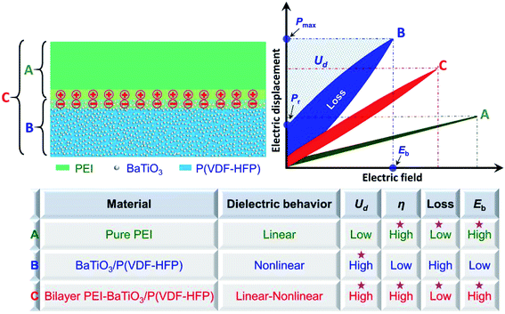
δ > 0.1 @ 1 kHz), which cannot meet the requirements of practical applications. In other words, more attention should be paid to the concurrent improvement of Ud and η rather than solely Ud. As we know, linear dielectric polymers (e.g., polyetherimide, polypropylene, polyimide, and polymethyl methacrylate) have a very high η (>95%) and low loss (tan![[thin space (1/6-em)]](https://www.rsc.org/images/entities/char_2009.gif) δ < 0.05 @ 1 kHz).2,19 With the aim of achieving balanced energy density and discharge efficiency, we herein report a novel design of bilayer dielectric composites consisting of a pure polyetherimide (PEI) layer and a BaTiO3/P(VDF-HFP) composite layer. In comparison with a trilayer composite which has two layer/layer interfaces, a bilayer composite possesses only one layer/layer interface. Therefore, the loss induced by the interfacial polarization at the interfaces between adjacent layers could be suppressed in the bilayer composite, which is favorable for the achievement of high efficiency and low loss. As shown in Fig. 1, the linear dielectric layer PEI offers high efficiency η, low loss, and high breakdown strength Eb, while the nonlinear dielectric BaTiO3/P(VDF-HFP) composite layer provides high energy density Ud. Consequently, the bilayer composites may combine the superiorities of the two layers, yielding simultaneously high η, high Ud, high Eb, and low loss. Interestingly, our results show that all of the bilayer composites exhibit ultrahigh η values over 95% which are much higher than those of most of the so far reported polymer dielectric composites (η < 80%) under external electric fields up to 400 kV mm−1. Moreover, a low loss (tan
δ < 0.05 @ 1 kHz).2,19 With the aim of achieving balanced energy density and discharge efficiency, we herein report a novel design of bilayer dielectric composites consisting of a pure polyetherimide (PEI) layer and a BaTiO3/P(VDF-HFP) composite layer. In comparison with a trilayer composite which has two layer/layer interfaces, a bilayer composite possesses only one layer/layer interface. Therefore, the loss induced by the interfacial polarization at the interfaces between adjacent layers could be suppressed in the bilayer composite, which is favorable for the achievement of high efficiency and low loss. As shown in Fig. 1, the linear dielectric layer PEI offers high efficiency η, low loss, and high breakdown strength Eb, while the nonlinear dielectric BaTiO3/P(VDF-HFP) composite layer provides high energy density Ud. Consequently, the bilayer composites may combine the superiorities of the two layers, yielding simultaneously high η, high Ud, high Eb, and low loss. Interestingly, our results show that all of the bilayer composites exhibit ultrahigh η values over 95% which are much higher than those of most of the so far reported polymer dielectric composites (η < 80%) under external electric fields up to 400 kV mm−1. Moreover, a low loss (tan![[thin space (1/6-em)]](https://www.rsc.org/images/entities/char_2009.gif) δ < 0.05 @ 10 kHz) comparable to that of the pure PEI is also achieved. Furthermore, the bilayer composites show impressive improvements in Eb, i.e., 285%, 363%, 366% and 567% for composites with 5 vol%, 10 vol%, 20 vol% and 40 vol% BaTiO3, compared to their single-layer counterparts, thus resulting in obviously improved Ud. The outstanding dielectric characteristics make these bilayer composites promising candidates for high-performance energy-storage capacitors.
δ < 0.05 @ 10 kHz) comparable to that of the pure PEI is also achieved. Furthermore, the bilayer composites show impressive improvements in Eb, i.e., 285%, 363%, 366% and 567% for composites with 5 vol%, 10 vol%, 20 vol% and 40 vol% BaTiO3, compared to their single-layer counterparts, thus resulting in obviously improved Ud. The outstanding dielectric characteristics make these bilayer composites promising candidates for high-performance energy-storage capacitors.
2. Experimental
2.1. Materials
Barium titanate (BaTiO3, <3 μm, >99.5%, Aladdin Industrial Corporation), poly(vinylidene fluoride-hexafluoropropylene) (P(VDF-HFP), 15% HFP, PolyK Technologies, USA), polyetherimide (PEI, PolyK Technologies, USA), 1-methyl-2-pyrrolidone (C5H9NO, ≥99.0% Sinopharm Chemical Reagent Co., Ltd.), sodium dodecylbenzenesulfonate (C18H29NaO3, ≥88.0%, Sinopharm Chemical Reagent Co., Ltd.) and ethanol (≥99.7%, Sinopharm Chemical Reagent Co., Ltd.).2.2. Preparation of bilayer composites
Firstly, a BaTiO3/P(VDF-HFP) suspension and PEI solution were prepared. For the preparation of the BaTiO3/P(VDF-HFP) suspension, BaTiO3 particles and sodium dodecylbenzenesulfonate (SDBS) were ultrasonically dispersed into 10 mL 1-methyl-2-pyrrolidone (NMP) for 1 h at room temperature to obtain a stable suspension, followed by adding P(VDF-HFP) pellets into the suspension with magnetic stirring at 75 °C until the P(VDF-HFP) pellets were dissolved completely. For the preparation of the PEI solution, PEI particles were directly dissolved in 1-methyl-2-pyrrolidone (NMP) with rapid magnetic stirring at 75 °C for 5 h and mild stirring at room temperature overnight. Then the BaTiO3/P(VDF-HFP) suspension and PEI solution were cast on glass plates separately. The thicknesses of the single-layer composites were controlled in the range of 15–20 μm by adjusting the height of blade. Then the films along with the glass plates were transferred to an oven and dried at 100 °C for 4 h and 200 °C for 5 min. Subsequently, the films were peeled off via quenching in ice water and dried in an oven at 70 °C for 6 h, yielding the single layer BaTiO3/P(VDF-HFP) composite films and PEI films. Finally, bilayer films with different BaTiO3 contents were obtained via stacking and hot-pressing a BaTiO3/P(VDF-HFP) composite film and a PEI film at 150 °C under a pressure of 6 MPa for 5 min. In this paper, the single layer BaTiO3/P(VDF-HFP) composites and bilayer composites were denoted as α vol% BT/PVDF and PEI-α vol% BT/PVDF, respectively, where α represents the volume fraction of BaTiO3 in the BaTiO3/P(VDF-HFP) composites.2.3. Characterization and measurements
The morphologies of the bilayer films and elemental distributions of barium and carbon were observed by scanning electron microscopy (SEM, S-4800, Hitachi, Ltd.) combined with EDX. Circular gold electrodes with a diameter of 2.98 mm were sputtered on the two sides of the samples before dielectric measurements. The dielectric properties were analyzed with an Agilent E4980A Precision LCR analyzer in the frequency range from 100 Hz to 1 MHz. Open and short compensations were performed before testing. The permittivity was calculated using εr = tCp/Aε0, where t is the thickness of the sample, A is the area of the electrode, Cp is the parallel capacitance, f is the electric field frequency, and ε0 is the absolute permittivity of free space (8.85 × 10⁻¹² F m−1). The breakdown strengths were obtained using a setup equipped with a Trek 609A amplifier with a voltage ramping rate of 500 V s−1 at room temperature (PolyK Technologies, USA). The energy storage performances, including discharge energy densities and charge–discharge efficiencies, were obtained using P–E hysteresis loops which were collected at 1 kHz using a ferroelectric test system based on a modified Sawyer-Tower circuit (PolyK Technologies, USA).3. Results and discussion
The optical photograph and cross-sectional SEM morphologies of the PEI-20 vol% BT/PVDF bilayer composite are presented in Fig. 2a–d. As can be seen, the bilayer film is flexible and has smooth surfaces. The SEM image confirms the distinct bilayer configuration, in which the two layers are tightly welded together without the appearance of noticeable defects (e.g., pores, cracks, voids, etc.). Moreover, the high-magnification cross-sectional SEM images shown in Fig. S1† demonstrate that the BaTiO3 particles are homogeneously dispersed in the P(VDF-HFP) matrix. The EDX mapping results further demonstrate that the BaTiO3 particles are well restricted in the P(VDF-HFP) matrix without apparent diffusion into the PEI layer. Furthermore, the total thickness of the film is ∼25 μm, where the BT/PVDF layer is ∼6.6 μm while the PEI layer is ∼18.4 μm. As we know, in a single-layer composite consisting of ferroelectric fillers (e.g., BaTiO3) dispersed in a linear dielectric matrix (e.g., PEI, PMMA, and PI), the ferroelectric fillers offer high energy-storage density while the matrix maintains the high energy-storage efficiency. As the loading fraction of ferroelectric fillers increases, the energy density increases and the efficiency decreases.38,39 Similarly, in the bilayer-structured composites, the linear dielectric PEI layer is expected to contribute to the improved energy-storage efficiency, while the ferroelectric BaTiO3/P(VDF-HFP) layer could suppress the efficiency because of its strong polarization-induced energy loss. Therefore, to achieve high efficiency, the volume fractions of ferroelectric BaTiO3 and P(VDF-HFP) in the bilayer composites should be lowered. In this regard, the PEI layer is designed to be much thicker than the BaTiO3/P(VDF-HFP) layer. However, it should be noted that the increasing thickness ratio of the PEI layer to the BaTiO3/P(VDF-HFP) layer would also result in suppressed energy-storage density. As shown in Fig. S1,† the thickness ratios of the BT/PVDF layer to the PEI layer for all the bilayer composites are almost the same, i.e., ∼0.36. Accordingly, the volume ratio of the BT/PVDF layer to the PEI layer is about 0.36, and the actual volume fractions of BaTiO3 in the PEI-5 vol% BT/PVDF, PEI-10 vol% BT/PVDF, PEI-20 vol% BT/PVDF and PEI-40 vol% BT/PVDF composites are 1.8%, 3.6%, 7.2% and 14.4%, respectively.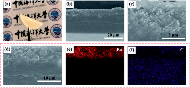 | ||
| Fig. 2 (a) Photograph, (b–d) cross-sectional SEM morphologies and (e and f) corresponding EDX mapping images of the PEI-20 vol% BT/PVDF bilayer composite. | ||
The frequency dependences of dielectric permittivity and loss tangent for single layer and bilayer composites is displayed in Fig. 3. As shown in Fig. 3a, the pure PEI film shows the lowest permittivity and is almost independent of frequency in the tested frequency range. The pure P(VDF-HFP) has a much higher permittivity than pure PEI and exhibits apparent frequency dispersion behavior. The permittivities of the BaTiO3/P(VDF-HFP) composites increase with higher BaTiO3 loadings, which could be attributed to the strong inherent dipolar polarization inside the ferroelectric BaTiO3 particles. In addition, the interfacial polarization of the accumulated charges at the interfaces between BaTiO3 particles and the P(VDF-HFP) matrix may also contribute to the enhanced dielectric permittivity. Correspondingly, the pure PEI film possesses the lowest loss, while the pure PVDF and BaTiO3/P(VDF-HFP) composites exhibit much higher loss than PEI (see Fig. 3b). For instance, the loss tangents of the composites with 10 vol% and 20 vol% BaTiO3 come up to above 0.1 @ 10 kHz, which may result in a huge amount of undesired heat production, thus deteriorating the performance stability and shortening the service life of the electronic devices. As shown in Fig. 3c and d, the bilayer composites display moderate dielectric permittivities that are between those of the corresponding single layer BaTiO3/P(VDF-HFP) composites and the pure PEI layer. Fortunately, low dielectric loss (tan![[thin space (1/6-em)]](https://www.rsc.org/images/entities/char_2009.gif) δ < 0.05 @ 10 kHz) is achieved in the bilayer composites which will greatly facilitate their practical application.
δ < 0.05 @ 10 kHz) is achieved in the bilayer composites which will greatly facilitate their practical application.
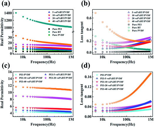 | ||
| Fig. 3 Frequency dependences of dielectric permittivity and loss tangent for (a and b) single layer and (c and d) bilayer composites. | ||
It should be noted that the magnitude of dielectric permittivity can only determine the energy density of a dielectric material under a certain electric field. In addition to permittivity, the maximum electric field that a dielectric material can withstand before failure (i.e., breakdown strength Eb) is another crucial parameter for dielectric energy-storage materials, especially for their applications under high electric fields. Therefore, the breakdown strengths of the composites are further evaluated using the two-parameter Weibull distribution, which is described by eqn (1):
 | (1) |
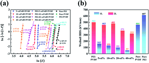 | ||
| Fig. 4 (a) Weibull distribution plots and (b) characteristic breakdown strengths of the single layer and bilayer composites with different BaTiO3 loading fractions. | ||
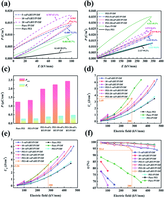
The unipolar electric displacement–electric field (P–E) loops for the single layer and bilayer composites are illustrated in Fig. 5, S3 and S4.† Slim (or narrow) loops imply a weak deviation from the linear dielectric behavior and correspond to a low energy loss. Clearly, the pure P(VDF-HFP) shows much wider loops than the pure PEI, and the introduction of BaTiO3 particles further widens the loops, indicative of enhanced energy loss and suppressed efficiency (see Fig. 5a). The bilayer composites possess slim loops located between those of the pure PEI and pure P(VDF-HFP), and no serious broadening phenomenon is observed in the loops under elevated electric fields (see Fig. 5b and S4†). Fig. 5c depicts the displacements of the pure PEI and bilayer composites with varied BaTiO3 loading fractions at 350 kV mm−1. As can be see, the bilayer composites exhibit substantially improved Pmax (>2 μC cm−2) compared with the pure PEI (∼1.25 μC cm−2) which is induced by the introduction of the ferroelectric BT/P(VDF-HFP) layer with strong dipolar and interfacial polarizations. In contrast, only slight increments of Pr (<0.25 μC cm−2) are observed, yielding an increased value of (Pmax − Pr) which is beneficial for the concurrent improvement of energy density and efficiency. Moreover, the Pmax values of the composites become higher with increasing loading fractions of BaTiO3 which should be ascribed to the high Pmax (∼0.085 C m−2 at 3 kV mm−1) of pure BaTiO3 (see Fig. S3b†). However, a higher BaTiO3 content also brings about enhanced deviations of P–E loops from linear behavior, leading to suppressed energy-storage performance. As can be seen in Fig. S5,† the PEI-40 vol% BT/PVDF composite shows a higher Pmax than the other bilayer composites with low BaTiO3 contents under the same charged electric field. However, its breakdown strength is obviously lower than those of the other bilayer composites. Consequently, it can only be charged to 280 kV mm−1 and the corresponding efficiency is lower than that of the other bilayer composites. In other words, higher BaTiO3 results in higher energy density but lower breakdown strength and lower efficiency. Furthermore, the stored energy densities (Us) of the composites were derived from the P–E loops (see Fig. 5d and e, S3 and S4†) by integration of the area between the charge curve and the ordinate, while the discharge energy densities (Ud) were obtained by integrating the area between the discharge curve and the ordinate, and the discharge efficiencies η were calculated using η = Ud/Us. As illustrated in Fig. 5e, although the single layer BT/P(VDF-HFP) composites show higher Ud than the corresponding bilayer composites at low electric fields (<200 kV mm−1) as a result of their high permittivities, they cannot be used as energy storage materials under high electric fields owing to their low Eb as aforementioned. In contrast, the bilayer composites display superior Ud under high electric fields and their energy densities are much higher than that of the pure PEI. In particular, a high energy density of ∼6.0 J cm−3 under an electric field of 450 kV mm−1 is achieved in the bilayer composite with 10 vol% BaTiO3. The discharge efficiencies η of the composites under different electric fields are illustrated in Fig. 5f. Apparently, ultrahigh η (>95%) values, which are much higher than those of the single layer pure P(VDF-HFP) and BT/P(VDF-HFP) composites, are achieved. In the bilayer composites, the ultrahigh discharge efficiencies are mainly contributed by the introduction of the linear dielectric polymer PEI. On one hand, the aforementioned low volume fractions of ferroelectric phases, including BaTiO3 and P(VDF-HFP), result in a low energy loss induced by ferroelectric polarizations, hence the efficiency is high. On the other hand, the excellent insulating properties of the PEI layer ensure high breakdown strengths of the bilayer composites which can effectively suppress the ohmic heat loss induced by leakage conductance and deliver a high discharge efficiency. Furthermore, the ultrahigh η values are well maintained even under high electric fields up to 450 kV mm−1. In particular, the bilayer composite with 10 vol% BaTiO3 exhibits an extremely high η of ∼96.8% at 450 kV mm−1 which is almost as high as that of the pure PEI (η ∼ 98.2%). In contrast, the η values of the single-layer BT/P(VDF-HFP) composites become sharply deteriorated with increasing electric fields. As discussed above, the combination of linear and nonlinear dielectric polymers via constructing bilayer composites gives rise to comprehensively enhanced energy-storage performances.
Fig. 6 compares the discharge efficiencies and energy densities of this work and of recently reported single layer, bilayer, trilayer and multilayer (>3 layers) polymer composites from other research groups.40–51 We can see that the composites using a linear dielectric polymer matrix (e.g., BNNS/PMMA composites in ref. 46 and BaTiO3/PI composites in ref. 47) display relatively higher discharge efficiencies (>80%) than those composites based on nonlinear dielectric polymers (e.g., PVDF and its copolymers). It is worth noting that our bilayer PEI-10 vol% BaTiO3/P(VDF-HFP) composite exhibits a much higher discharge efficiency (∼96.8%) than most of the so far reported polymer based dielectric composites. Meanwhile, a high energy density of ∼6 J cm−3 is also obtained. For a long time, the research on dielectric energy-storage materials was mainly targeted at solely achieving high energy density. In contrast, the discharge efficiency and loss that are key parameters in practical applications gained limited attention. The simultaneous realization of ultrahigh discharge efficiency and high energy density, low loss, and high breakdown strength makes these bilayer composites ideal candidates for applications in high-performance dielectric energy-storage devices.
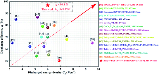 | ||
| Fig. 6 Comparison of energy density and efficiency of this work (PEI-10 vol% BaTiO3/P(VDF-HFP) composite) and reported results. | ||
4. Conclusion
In summary, a class of bilayer composites consisting of a pure polyetherimide layer and a BaTiO3/P(VDF-HFP) composite layer were fabricated via solution casting and hot pressing. The bilayer composites show impressive improvements in breakdown strengths, i.e., 285%, 363%, 366% and 567% for composites with 5 vol%, 10 vol%, 20 vol% and 40 vol% BaTiO3 particles, in comparison with their single layer counterparts, thus resulting in obviously improved Ud. More notably, the bilayer composites exhibit ultrahigh discharge efficiencies over 95%, which are much higher than most of the so far reported results, under external electric fields up to 400 kV mm−1. In particular, the bilayer composite with 10 vol% BaTiO3 exhibits an ultrahigh discharge efficiency of ∼96.8% and a high energy density of 6 J cm−3 at 450 kV mm−1, along with a low loss tangent of ∼0.025 @ 10 kHz. It is believed that, in the bilayer composites, the pure polyetherimide layer ensures high efficiency, high breakdown strength and low loss, while the BaTiO3/P(VDF-HFP) composite layer offers high energy density. The synergy of the two layers brings about concurrently enhanced discharge efficiency and energy density. The excellent dielectric performances greatly promote the practical applications of these bilayer composites in advanced energy-storage devices. Hopefully, layer-structured composites with further improved dielectric properties may be developed via sufficiently exploring the synergic effects of the linear and nonlinear dielectric layers.Conflicts of interest
There are no conflicts to declare.Acknowledgements
The authors acknowledge the financial support of this work from the National Natural Science Foundation of China (51773187 and 51402271) and Foundation for Outstanding Young Scientist in Shandong Province (BS2014CL003).References
- X. Y. Huang, B. Sun, Y. K. Zhu, S. T. Li and P. K. Jiang, Prog. Mater. Sci., 2019, 100, 187–225 CrossRef CAS.
- H. Luo, X. F. Zhou, C. Ellingford, Y. Zhang, S. Chen, K. C. Zhou, D. Zhang, C. R. Bowen and C. Y. Wang, Chem. Soc. Rev., 2019, 48, 4424–4465 RSC.
- H. Pan, F. Li, Y. Liu, Q. H. Zhang, M. Wang, S. Lan, Y. P. Zheng, J. Ma, L. Gu, Y. Shen, P. Yu, S. J. Zhang, L. Q. Chen, Y. H. Li and C. W. Nan, Science, 2019, 365, 578–582 CrossRef CAS PubMed.
- Z. P. Li, X. Y. Chen, C. Zhang, E. Baer, D. Langhe, M. Ponting, M. Brubaker, T. Hosking, R. P. Li, M. Fukuto and L. Zhu, ACS Appl. Polym. Mater., 2019, 1, 867–875 CrossRef CAS.
- Q. Y. Zhao, L. Yang, K. N. Chen, Y. Z. Ma, H. L. Ji, M. X. Shen, H. J. Huang, H. Y. He and J. H. Qiu, Nano Energy, 2019, 65, 104007 CrossRef CAS.
- X. T. Zhu, J. Yang, D. Dastan, H. Garmestani, R. H. Fan and Z. C. Shi, Composites, Part A, 2019, 125, 105521 CrossRef.
- J. Yang, X. T. Zhu, H. L. Wang, X. Wang, C. C. Hao, R. H. Fan, D. Dastan and Z. C. Shi, Composites, Part A, 2020, 131, 105814 CrossRef.
- Y. N. Hao, X. H. Wang, K. Bi, J. M. Zhang, Y. H. Huang, L. W. Wu, P. Y. Zhao, K. Xu, M. Lei and L. T. Li, Nano Energy, 2017, 31, 49–56 CrossRef CAS.
- C. Zhang, Z. C. Shi, F. Mao, C. Q. Yang, J. Yang, X. T. Zhu and H. Zuo, J. Mater. Sci., 2018, 53, 1–13 CrossRef.
- L. M. Yao, Z. B. Pan, J. W. Zhai, G. Z. Zhang, Z. Y. Liu and Y. H. Liu, Composites, Part A, 2018, 109, 48–54 CrossRef CAS.
- Z. B. Pan, B. H. Liu, J. W. Zhai, L. M. Yao, K. Yang and B. Shen, Nano Energy, 2017, 40, 587–595 CrossRef CAS.
- Z. C. Shi, S. G. Chen, R. H. Fan, X. A. Wang, X. Wang, Z. D. Zhang and K. Sun, J. Mater. Chem. C, 2014, 2, 6752 RSC.
- X. Huang, X. Zhang, G. K. Ren, J. Y. Jiang, Z. K. Dan, Q. H. Zhang, X. Zhang, C. W. Nan and Y. Shen, J. Mater. Chem. A, 2019, 7, 15198 RSC.
- P. T. Xie, Y. F. Li, Q. Hou, K. Y. Sui, C. Z. Liu, X. Y. Fu, J. X. Zhang, V. Murugadoss, J. C. Fan, Y. P. Wang, R. H. Fan and Z. H. Guo, J. Mater. Chem. C, 2020, 8, 3029–3039 RSC.
- B. Xie, Y. W. Zhu, M. A. Marwat, S. J. Zhang, L. Zhang and H. B. Zhang, J. Mater. Chem. A, 2018, 6, 20356 RSC.
- W. Y. Li, Z. Q. Song, J. Qian, Z. Y. Tan, H. Y. Chu, X. Y. Wu, W. Nie and X. H. Ran, Carbon, 2019, 141, 728–738 CrossRef CAS.
- K. Sun, J. N. Dong, Z. X. Wang, Z. Y. Wang, G. H. Fan, Q. Hou, L. Q. An, M. Y. Dong, R. H. Fan and Z. H. Guo, J. Phys. Chem. C, 2019, 123, 23635–23642 CrossRef CAS.
- L. Zhang, Z. Liu, X. Lu, G. Yang, X. Y. Zhang and Z. Y. Cheng, Nano Energy, 2016, 26, 550–557 CrossRef CAS.
- B. H. Fan, M. Y. Zhou, C. Zhang, D. L. He and J. B. Bai, Prog. Polym. Sci., 2019, 97, 101143 CrossRef CAS.
- M. F. Guo, J. Y. Jiang, Z. H. Shen, Y. H. Lin, C. W. Nan and Y. Shen, Mater. Today, 2019, 29, 49–67 CrossRef CAS.
- K. Bi, M. H. Bi, Y. N. Hao, W. Luo, Z. M. Cai, X. H. Wang and Y. H. Huang, Nano Energy, 2018, 51, 513–523 CrossRef CAS.
- G. Jian, M. R. Liu, C. Yan, F. Wu, B. Song, K. S. Moon and C. P. Wong, Nano Energy, 2019, 58, 419–426 CrossRef CAS.
- M. S. Zheng, Y. T. Zheng, J. W. Zha, Y. Yang, P. Han, Y. Q. Wen and Z. M. Dang, Nano Energy, 2018, 48, 144–151 CrossRef CAS.
- Y. Yang, Z. S. Gao, M. H. Yang, M. S. Zheng, D. R. Wang, J. W. Zha, Y. Q. Wen and Z. M. Dang, Nano Energy, 2019, 59, 363–371 CrossRef CAS.
- Z. Y. Wang, K. Sun, P. T. Xie, Q. Hou, Y. Liu, Q. L. Gu and R. H. Fan, Acta Mater., 2020, 185, 412–419 CrossRef CAS.
- Q. L. Fan, C. R. Ma, Y. Li, Z. S. Liang, S. Cheng, M. Y. Guo, Y. Z. Dai, C. S. Ma, L. Lu, W. Wang, L. H. Wang, X. J. Lou, M. Liu, H. Wang and C. L. Jia, Nano Energy, 2019, 62, 725–733 CrossRef CAS.
- J. Y. Jiang, Z. H. Shen, J. F. Qian, Z. K. Dan, M. F. Guo, Y. He, Y. H. Lin, C. W. Nan, L. Q. Chen and Y. Shen, Nano Energy, 2019, 62, 220–229 CrossRef CAS.
- B. Xie, Q. Zhang, L. Zhang, Y. W. Zhu, X. Guo, P. Y. Fan and H. B. Zhang, Nano Energy, 2018, 54, 437–446 CrossRef CAS.
- Z. X. Sun, C. R. Ma, M. Liu, J. Cui, L. Lu, J. B. Lu, X. J. Lou, L. Jin, H. Wang and C. L. Jia, Adv. Mater., 2017, 29, 1604427 CrossRef PubMed.
- Z. C. Shi, J. Wang, F. Mao, C. Q. Yang, C. Zhang and R. H. Fan, J. Mater. Chem. A, 2017, 5, 14575 RSC.
- J. Wang, Z. C. Shi, F. Mao, S. G. Chen and X. Wang, ACS Appl. Mater. Interfaces, 2017, 9, 1793–1800 CrossRef CAS PubMed.
- J. Chen, Y. F. Wang, X. W. Xu, Q. B. Yuan, Y. J. Niu, Q. Wang and H. Wang, J. Mater. Chem. A, 2019, 7, 3729 RSC.
- Y. F. Wang, L. X. Wang, Q. B. Yuan, J. Chen, Y. J. Niu, X. W. Xu, Y. T. Cheng, B. Yao, Q. Wang and H. Wang, Nano Energy, 2018, 44, 364–370 CrossRef CAS.
- C. Jie, Y. F. Wang, Q. B. Yuan, X. W. Xu, Y. J. Niu, Q. Wang and H. Wang, Nano Energy, 2018, 54, 288–296 CrossRef.
- Y. F. Wang, J. Chen, Y. Li, Y. J. Niu, Q. Wang and H. Wang, J. Mater. Chem. A, 2019, 7, 2965 RSC.
- Y. F. Wang, Y. Li, L. X. Wang, Q. B. Yuan, J. Chen, Y. J. Niu, X. W. Xu, Q. Wang and H. Wang, Energy Storage Materials, 2020, 24, 626–634 CrossRef.
- C. Zhang, Z. C. Shi, F. Mao, C. Q. Yang, X. T. Zhu, J. Yang, H. Zuo and R. H. Fan, ACS Appl. Mater. Interfaces, 2018, 10, 26713–26722 CrossRef CAS PubMed.
- Y. Feng, Y. H. Zhou, T. D. Zhang, C. H. Zhang, Y. Q. Zhang, Y. Zhang, Q. G. Chen and Q. G. Chi, Energy Storage Materials, 2020, 25, 180–192 CrossRef.
- Y. Zhang, C. H. Zhang, Y. Feng, T. D. Zhang, Q. G. Chen, Q. G. Chi, L. Z. Liu, X. Wang and Q. Q. Lei, Nano Energy, 2019, 64, 104195 CrossRef.
- D. Zhang, W. W. Liu, R. Guo, K. C. Zhou and H. Luo, Adv. Sci., 2018, 5, 1700512 CrossRef PubMed.
- H. J. Ye, T. M. Lu, C. F. Xu, M. Q. Zhong and L. X. Xu, Nanotechnology, 2018, 29, 095702 CrossRef PubMed.
- H. J. Ye, X. H. Zhang, C. F. Xu, B. Han and L. X. Xu, J. Mater. Chem. C, 2018, 6, 11144–11155 RSC.
- Z. B. Pan, L. M. Yao, J. W. Zhai, H. T. Wang and B. Shen, ACS Appl. Mater. Interfaces, 2017, 9, 14337–14346 CrossRef CAS PubMed.
- L. Wang, H. Luo, X. F. Zhou, X. Yuan, K. C. Zhou and D. Zhang, Composites, Part A, 2019, 117, 369–376 CrossRef CAS.
- M. A. Marwat, B. Xie, Y. W. Zhu, P. Y. Fan, W. G. Ma, H. M. Liu, M. Ashtar, J. Z. Xiao, D. Salamon, C. Samater and H. B. Zhang, Composites, Part A, 2019, 121, 115–122 CrossRef CAS.
- F. H. Liu, Q. Li, Z. Y. Li, Y. Liu, L. J. Dong, C. X. Xiong and Q. Wang, Compos. Sci. Technol., 2017, 142, 139–144 CrossRef CAS.
- W. D. Sun, X. J. Lu, J. Y. Jiang, X. Zhang, P. H. Hu, M. Li, Y. H. Lin, C. W. Nan and Y. Shen, J. Appl. Phys., 2017, 121, 244101 CrossRef.
- Q. G. Chi, X. B. Wang, C. H. Zhang, Q. G. Chen, M. H. Chen, T. D. Zhang, L. Gao, Y. Zhang, Y. Cui, X. Wang and Q. Q. Lei, ACS Sustainable Chem. Eng., 2018, 6, 8641–8649 CrossRef CAS.
- Y. Zhang, T. D. Zhang, L. Z. Liu, Q. G. Chi, C. H. Zhang, Q. G. Chen, Y. Cui, X. Wang and Q. Q. Lei, J. Phys. Chem. C, 2018, 122, 1500–1512 CrossRef CAS.
- W. Y. Li, Z. Q. Song, J. M. Zhong, J. Qian, Z. Y. Tan, X. Y. Wu, H. Y. Chu, W. Nie and X. H. Ran, J. Mater. Chem. C, 2019, 7, 10371 RSC.
- M. A. Marwat, B. Xie, Y. W. Zhu, P. Y. Fan, K. Liu, M. Shen, M. Ashtar, S. Kongparakul, C. Samater and H. B. Zhang, Colloids Surf., A, 2019, 581, 123802 CrossRef CAS.
Footnote |
| † Electronic supplementary information (ESI) available. See DOI: 10.1039/d0ta00903b |
| This journal is © The Royal Society of Chemistry 2020 |

