 Open Access Article
Creative Commons Attribution 3.0 Unported Licence
Synthesis of material libraries using gas diffusion electrodes†
Rafael A.
Prato M.
ab,
Vincent
Van Vught
a,
Kudakwashe
Chayambuka
cde,
Guillermo
Pozo
af,
Sam
Eggermont
bf,
Jan
Fransaer
bf and
Xochitl
Dominguez-Benetton
 *af
*af
aSustainable Chemistry, VITO, Flemish Institute for Technological Research, Boeretang 200, 2400, Mol, Belgium. E-mail: xoch@vito.be
bDepartment of Materials Engineering, Surface and Interface Engineered Materials, Katholieke Universiteit Leuven, Kasteelpark Arenberg 44 - box 2450, 3001 Leuven, Belgium
cSustainable Energy, VITO, Flemish Institute for Technological Research, Boeretang 200, 2400, Mol, Belgium
dEnergyVille, Thor Park 8310, 3600 Genk, Belgium
eEindhoven University of Technology, Postbus 513, 5600 MB, Eindhoven, The Netherlands
fSIM vzw, Technologiepark 935, BE-9052 Zwijnaarde, Belgium
First published on 4th June 2020
Abstract
The future of energy relies on the advent of electrochemical energy production and storage. A key enabling factor is the effective synthesis of active materials, which, due to the global environmental circumstances and the growing demand, we must ensure are made sustainably. Thus, we unveil a rapid, sustainable, and scalable electrosynthesis route for a whole range of nanocrystalline materials with bright prospects for batteries, solar fuels and fuel cells, among others. For the proof of concept of the synthesis method, gas-diffusion electrocrystallization (GDEx), we synthesize manganese and cobalt oxides and hydroxides: Co-doped Na-birnessite, cubic/tetragonal spinels and layered double hydroxides (CoMn-LDH), owing to their current relevance. An oxygen depolarizing gas-diffusion electrode is used to fuel the oxidative synthesis at the electrochemical interface. Aside from the necessary metal precursors, all reagents are produced in situ with high efficiency. To elucidate the synthesis mechanism, a broad range of materials were produced under the same conditions. By changing the Co and Mn concentrations in the feed solution, the composition (Co/Mn stoichiometry), morphology (spinels vs. nanosheets), structure (tetragonal/cubic-spinel, birnessite, LDH), particle size (15–35 nm), crystallinity (polycrystalline particles vs. single-crystals), and phase purity were precisely tailored. A comprehensive library of nanostructures was built, wherein some materials exhibited outstanding catalytic properties for the oxygen evolution reaction, illustrating the significance of our strategy. To showcase the versatility of the method, we also prove the feasibility for sodium intercalation capacity in the materials, applicable to batteries. This work opens the door to a new systematic way of producing optimized and affordable materials for electrochemical energy applications and beyond.
Introduction
The development of next-generation electrochemical energy technologies plays a key role in the future of sustainable energy. To meet the increasing demand for high-performance energy devices, how we fabricate electrochemically active materials must be transformed. First, we need methods that can develop into potent tools for high-throughput synthesis and screening, especially of nanostructures with outstanding performance.1 Today, this mostly implies trial and error strategies, making the development rather sluggish. Second, we are accountable for developing and using sustainable, environmentally innocuous, production methods. Ideally, these should be chemically and energetically thrifty, operate under mild conditions, avoid the use of hazardous chemicals, and not generate waste materials.Metal-air batteries, solar fuels, and fuel cells are among the technologies driving the study and development of better electrocatalysts. The oxygen reduction (ORR) and evolution (OER) reactions2–4 are by far the most important transformations in this regard. The optimization of electrochemically active materials in terms of structure and composition is difficult, given the broad range of possibilities. Varying synthesis conditions yield different particle sizes, morphologies, crystallinity, and ultimately, affordability.2 Due to much lower costs and ready availability, manganese-containing mixed oxides and hydroxides have emerged as alternatives to noble metal catalysts, with certain materials matching or surpassing the performance of IrO2 (OER) and Pt/C (ORR).5,6 Thus, we selected such materials to characterize our proof of concept, although our approach is far-reaching and can be contrasted with landmark strategies to synthesize nanomaterial libraries.1
One type of manganese dioxide, δ-MnO2, forms birnessite and birnessite-type compounds. These are layered oxides, composed of Mn–O octahedral plates that intercalate water. The redox activity of Mn allows some of the metal in the oxide layers to deviate from a 4+ to a 3+ valence, as electroneutrality is conserved by intercalating small cations, usually Mg2+, Li+, Na+, K+, etc.7 This makes birnessite-type MnO2 a natural candidate cathode material for alkali and alkali-earth batteries, supercapacitors, and electrocatalysis (ORR/OER).8
Another family of materials that has jumped to the forefront of research is that of layered double hydroxides (LDHs). Their potential as electrode materials arises from their high redox activity, ion intercalation capacity, and high specific capacitance.9 The design of LDHs, in terms of both the intercalated ion and the metal hydroxide composition, results in the targeting of specific properties, which, if thoroughly controlled, confer them unique synthetic identities. This is an area to be exploited to fully realize the potential of these materials.9
Both birnessites and LDHs are excellent precursors for the synthesis of spinels, since they allow for the even distribution of the cations. This a useful feature for synthesizing complex stoichiometries. An uneven distribution of metals is a routine problem in solid-state synthesis, which is the usual method employed for the production of complex spinels. Regardless of the precursors, spinels of the general formula Mn3−xCoxO4 are found in numerous applications, including batteries, fuel cells, and (electro)catalysis.10,11
Various state of the art Mn/Co-based materials have been synthesized by chemical precipitation,11 and hydrothermal12 and sol–gel methods,13 as efforts are made to steer away from the highly unsustainable solid-state techniques. Particularly in the case of spinels, which are traditionally synthesized at very high temperatures, these approaches yield particles which are crystalline, but often large and irregular.14 Efforts have been recently made to develop synthesis routes at room temperature for the production of spinels,10 birnessites,15 and layered double hydroxides (LDHs),16 due to the more sustainable implications. A common thread between these synthesis techniques is the chemical addition of different Co/Mn precursors, oxidants, or reductants, to achieve the desired structure. However, the large spread on the electrochemical performance of these materials reported in the literature emphasizes the lack of control and reproducibility when synthesizing them, especially in terms of their structure.17
Composition, crystallinity, morphology, and more features that define a synthetic identity, are key factors in establishing structure–property relationships for any given structural group of Mn/Co oxides18,—as well as for any other nanomaterial. These are closely related to the synthesis process; hence a rational comparison of the materials reported across the literature, resulting from different techniques, is difficult.
Ideally, large ranges of comparable materials with variable structures and compositions, should be synthesized rapidly and under the same operational conditions (e.g., synthesis route, flow, temperature, potential, chemical environment, etc.). Only in this way, reliable benchmarking of catalytic performances, conceptualization of mechanisms, and improvements towards the production of affordable and optimized materials, can be achieved. This systematic approach to the synthesis of a variety of materials with only slight changes to the synthesis conditions represents a valuable platform for future screening of materials. A demonstration of such an approach is provided here, on top of being a sustainable, rapid, and up-scalable alternative.
Experimental section
Synthesis by gas-diffusion electrocrystallization (GDEx)
The synthesis was made in an EC Micro Flow Cell (ElectroCell, MFC30009), using a three-electrode configuration, wherein a dimensionally stable anode (DSA) functioned as the counter electrode.It is to be noted that our choice for the counter electrode material or reaction had no relevance on the process or findings here reported, as only the cathodic half-cell is examined. The electrochemical cell schematic is shown in Fig. 1. A PTFE-bonded cold-rolled gas diffusion electrode (VITO CORE®) was used as the cathode; a metal frame in the cathode compartment acted as the current collector. A Zirfon® separator was used between the two electrolyte compartments. An Ag/AgCl reference electrode was placed in the catholyte chamber in close proximity to the gas-diffusion electrode (GDE) surface. The supporting electrolyte solution in all cases was composed of 0.5 M NaCl and sufficient HCl to set a pH of 3.5. The latter was added to avoid hydrolysis of the metal ions. The different solutions were prepared with anhydrous MnCl2 and CoCl2 (Sigma Aldrich) with total metal concentrations ranging from 1 mM to 5.5 mM, as measured by Inductively Coupled Plasma Optical Emission Spectrometry (ICP-OES). Each concentration was prepared for the pure metals, and for mixtures of Mn and Co with varying ratios, considering the referred total metal concentrations. The mixtures prepared contained Mn/Co mole fractions from 0 to 1. Anolyte solutions were made in the same way, except that no Mn or Co was added; only the supporting electrolyte and HCl for pH control were supplemented. Air was fed into the cell, through the hydrophobic backing of the GDE, at a flow rate of 1 L h−1 at an overpressure of 18 mbar (g), set by a water column at the gas outlet of the cell. The electrolyte solutions consisted of 1 L for both anolyte and catholyte, respectively. The catholyte solution was fed from the catholyte external reservoir (Fig. 1) and was collected in a separate bottle at the outlet (Fig. 1, i.e., particle suspension). The anolyte solution was recirculated to and from the same feed bottle (Fig. 1, i.e., anolyte reservoir). Peristaltic pumps (Watson-Marlow) were used to provide a liquid flow rate of 20 mL min−1. A constant current of −300 mA was applied for each synthesis.
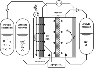 | ||
| Fig. 1 Electrochemical reactor sketch, showing the primary components used for the synthesis of nanomaterial libraries by gas-diffusion electrocrystallization (GDEx). | ||
The electrodes had a projected surface area of 10 cm2, facing towards the corresponding flow channel with a thickness of 0.4 cm, and a total of 4 ml of volume in each chamber. Under these conditions the residence time for incoming Mn2+/Co2+ ions in the cell was approximately 12 seconds.
Prior to each synthesis, the electrolyte with no transition metal was fed through the reactor in order to ensure sufficient wetting of the electrode and separator. The inlet of the reactor was then switched from the supporting electrolyte solution, to the catholyte reservoir to begin the synthesis. The chronopotentiometry (CP) was started and the outlet pH was monitored until it reached a steady value. To obtain continuous pH data from the very beginning of the experiments, 50 mL of electrolyte solution at pH 3.5 was added to the particle collection bottle. This ensured the availability of sufficient liquid to wet the pH probe. Once this was achieved, the catholyte outlet was switched to a new collection bottle.
After this startup process, the synthesis began. Once the experiment was finished (when the entire catholyte solution was consumed) the resulting colloidal suspension was centrifuged (Thermo Scientific Sorvall RC 6+), at 11![[thin space (1/6-em)]](https://www.rsc.org/images/entities/char_2009.gif) 000 rpm for 15 minutes. The supernatant solution was removed, and the precipitate was washed with a NaOH solution with a pH set to that of the synthesis solution at the outlet, and mixed with a vortex. The new mixture was centrifuged again. This process was repeated 3 times to ensure that leftover NaCl from the electrolyte was removed from the particles. Finally, the supernatant was removed once again and the collected pellets were dried under a nitrogen atmosphere at room temperature, achieving dry powders.
000 rpm for 15 minutes. The supernatant solution was removed, and the precipitate was washed with a NaOH solution with a pH set to that of the synthesis solution at the outlet, and mixed with a vortex. The new mixture was centrifuged again. This process was repeated 3 times to ensure that leftover NaCl from the electrolyte was removed from the particles. Finally, the supernatant was removed once again and the collected pellets were dried under a nitrogen atmosphere at room temperature, achieving dry powders.
GDE electrochemical studies
The oxygen reduction reaction (ORR) at the GDE was characterized with Cyclic Voltammetry (CV) and Electrochemical Impedance Spectroscopy (EIS). The supporting electrolyte solution (no transition metals) was used for characterization in the same electrochemical cell, with varying NaCl concentrations (0.25 M and 0.5 M) and varying gases (air vs. O2). EIS measurements were taken at potentials between −0.3 VAg/AgCl and −0.5 VAg/AgCl on the ORR region of the previously taken CV, between 100 kHz and 10 mHz, at an amplitude of ∼7 mV (rms). Prior to each EIS measurement, the system was verified for stability, causality, linearity and finiteness.Structural characterization
The dry samples were analyzed by powder X-ray diffraction (XRD) in a PanAlytical X'Pert Pro diffractometer (Cu Kα radiation, λ = 1.5406 Å). Samples were crushed in a mortar and placed in standard silicon monocrystal sample holders. Measurements were performed with a spinner at 40 mA to 40 kV spending 4 s per step, with a step size of 0.04° 2θ in the 10–110° 2θ range. Rietveld refinements were performed in all samples to fit the profiles and extract the lattice parameters from the data using HighScore Plus software. Crystallite sizes were calculated using the Scherrer equation, τ = κλ/(β![[thin space (1/6-em)]](https://www.rsc.org/images/entities/char_2009.gif) cos
cos![[thin space (1/6-em)]](https://www.rsc.org/images/entities/char_2009.gif) θ), with crystallite size (τ), shape factor (Κ), line broadening factor (β), X-ray wavelength (λ) and Bragg angle (θ). Micrographs of the dry samples were taken with no further treatment, with an FEI Nova NanoSEM 450. Images presented were taken with secondary electrons and an accelerating voltage of 5.00 kV. EDS spectrometry was used to confirm chemical compositions.
θ), with crystallite size (τ), shape factor (Κ), line broadening factor (β), X-ray wavelength (λ) and Bragg angle (θ). Micrographs of the dry samples were taken with no further treatment, with an FEI Nova NanoSEM 450. Images presented were taken with secondary electrons and an accelerating voltage of 5.00 kV. EDS spectrometry was used to confirm chemical compositions.
Chemical characterization
Upon finishing a synthesis the chemical composition of the outlet solution and the solid particles was investigated. 2 mL samples of the inlet and outlet solution were analyzed by Inductively Coupled Plasma Optical Emission Spectrometry (ICP-OES). The chemical composition of the inlet solution was confirmed to be the intended one (from 1 mM to 5.5 mM) and the outlet solution was checked to ensure complete removal of the metals. The dry particles were digested in aqua regia, diluted and then measured in the ICP-OES as well to observe the metal composition of the material and compare it with the inlet solution metal ratio.Testing of electroactive materials
IR drop was corrected with high-frequency impedance prior to all measurements. The electrodes were cycled 100 times at 10 mV s−1, between 0.3 VSCE and 0.75 VSCE for electrochemical conditioning. After cycling, linear sweep voltammetries (LSV) were performed at 5 mV s−1 to collect the final data. Measurements were reproduced with samples synthesized separately, and each sample tested underwent the 100 cycle conditioning to achieve a stable value, followed by 3 LSVs at a lower scan rate (5 mV s−1) to confirm the values.
![[thin space (1/6-em)]](https://www.rsc.org/images/entities/char_2009.gif) :
:![[thin space (1/6-em)]](https://www.rsc.org/images/entities/char_2009.gif) PC (1
PC (1![[thin space (1/6-em)]](https://www.rsc.org/images/entities/char_2009.gif) :
:![[thin space (1/6-em)]](https://www.rsc.org/images/entities/char_2009.gif) 1, w/w), and a separator, Freudenberg Viledon (FS-5P, 220 μm), were used. The three-electrode set-up consisted of a sodium metal disk (18 mm diameter) and a sodium metal ring electrode embedded in the separator as the reference electrode.
1, w/w), and a separator, Freudenberg Viledon (FS-5P, 220 μm), were used. The three-electrode set-up consisted of a sodium metal disk (18 mm diameter) and a sodium metal ring electrode embedded in the separator as the reference electrode.
Results and discussion
Gas-diffusion electrocrystallization
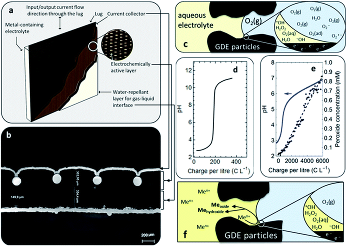
GDEx is a rapid one-pot reaction crystallization process, electrochemically steered at porous gas-diffusion electrodes (Fig. 2a and b), facing liquid electrolyte and a gas, wherein a triple-phase boundary is established (Fig. 2c). The multi-layered gas-diffusion electrodes include a hydrophobic outer layer through which the gas percolates, to ultimately be electrochemically reduced at a hydrophilic active layer (activated-carbon based), acting as a cathode. The active carbon powder constituting the gas-diffusion cathode is porous, including meso- and micro-pores, with an average pore diameter of 48 Å and a specific surface area of 745 m2 g−1, resulting in a highly reactive electrode. The total porosity of the gas-diffusion cathode manufactured by cold-rolling is 67%, out of which 29% corresponds to hydrophilic porosity and 38% to hydrophobic porosity, facilitating the electrolyte and gas transport, respectively. The specific surface area of the manufactured electrodes is 454 m2 g−1. A comprehensive description of these electrodes and the methods to characterize them can be found elsewhere.19The synthesis process proceeded in one step: a feed solution of MnCl2 and CoCl2 as the metal precursors, and 0.5 M NaCl as the supporting electrolyte, was fed through a flow cell equipped with a gas diffusion electrode (GDE). The formation of nanostructures by GDEx happens through the following steps. First, an oxidant gas (e.g., O2 in air) is forced through the hydrophobic backing on the electrically polarized porous cathode (Fig. 2a). After it diffuses to the electrocatalytic surface (e.g., hydrophilic activated carbon), the gas is reduced. For instance, by imposing specific cathodic polarization conditions (e.g., −0.145 VSHE), O2 is electro-reduced (Fig. 2c), to H2O2 in a 2 electron (2 e–) transfer process and H2O in a 4 electron (4 e–) transfer process, as per the following reactions:
| O2(g) + 2e− + 2H+(aq) → H2O2(aq) | (1) |
| O2(g) + 2e− + 2H2O(l) → HO−2(aq) + OH−(aq) | (2) |
Some polyatomic ions, peroxides, and free radicals are transient intermediaries formed together with OH− ions (Fig. 2c), as per the mechanism established for O2 reduction at non-catalyzed carbon electrodes.20 As this happens, abrupt local-pH and local-electrolyte potential changes arise rapidly within the cathode porosity. For instance, based on our experiments it is estimated (from the electric charge consumed), that the profuse amount of OH− rapidly produced (e.g., >1300 mol m−3), immediately results in a pH as high as 13–14 within the porosity of the cathode.21 As the hydroxyl ions spread to the bulk electrolyte, systematic pH increases become consistently manifest in the electrolyte bulk (Fig. 2d). In due course, lower amounts of H2O2 are generated (Fig. 1e), e.g. <1–5 mM, depending on the operational conditions employed and the amount of charge transferred per unit volume of catholyte. At the steady state, it is expected that a reaction front is fully developed throughout the hydrodynamic diffusion layer. This sets precedent for local saturation conditions at the electrochemical interface.
Throughout this work, both H2O2 and HO2−, will be referred to as HO2−. First, the analytical method employed serves for the indistinguishable quantification of both chemical species. Second, we grant that under the pH conditions prevalent at the steady-state in the bulk of most of the catholyte solutions investigated, H2O2 will be the more abundant chemical species (pKa = 11.65).22 However, at the electrochemical interface where the oxygen reduction reaction occurs, a profuse amount of OH− prevails, resulting in a local pH as high as 14.21 Thus, the conditions for HO2− to be stable are met in the vicinity of the gas-diffusion cathode and throughout the diffusion layer. It is, in fact, this phenomenon that facilitates the onset of hydroxide supersaturation23 and hence of the reactive precipitation (i.e., crystallization) of the different nanostructures, at the electrochemical interface (Fig. 2f).
The synthesis of nanostructures by GDEx provides very specific supersaturation conditions: (1) short nucleation and growth periods, (2) at high rates, and (3) avoiding the immediate agglomeration of the nanostructures formed.21 The flowing conditions impose only a temporary contact of metal ion precursors with the reactive species at the saturated electrochemical interface—rendering transient nucleation conditions. The possibilities of growth are feeble, as encountering other metal ions is restricted by their high dilution. The rate of interfacial processes typically scales with the available surface area (i.e., surface active sites), which is provided by the highly porous electrode, facilitating a high rate of production of HO2−, OH−, and their radicals, which quickly react with the metal ion precursors available at the interface. The reaction performance of a gas-diffusion electrode depends on the local environment within the porous active layer and the balance between transport phenomena and reaction kinetics.22 Specifically, the rate of the gas-reduction reaction depends on the concentration of dissolved gaseous species. In gas-diffusion electrodes, the pores in the active layer are wetted by a thin film of electrolyte, which minimizes the transport resistance of the gas into the electrocatalytic sites while maintaining a good ionic conductivity. Due to these phenomena, the current density in gas-diffusion electrodes can be two orders of magnitude of that of planar electrodes24 enabling fast reactivity at the electrochemical interface. Lastly, in analogy to growth, aggregation is restricted, as the nanoparticles dispersed in the aqueous solution are few, and then collisions between them are not likely. Otherwise, the particles can be easily transferred to pure water (i.e., using dialysis, or by centrifugation and resuspension), where they can set apart even better, as the repulsive forces become stronger (i.e., linked to double layer expansion as a result of the lower ionic strength—and sometimes pH—vs. those of the primary synthesis medium). The GDEx process is highly reproducible, and it involves mild synthetic conditions (e.g., 291 K and atmospheric pressure).
Particle synthesis
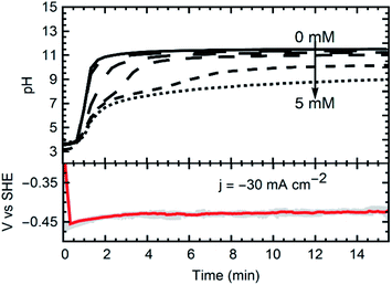
Currents were constant at −30 mA cm−2 for all experiments. The materials synthesized were collected at the outlet of the catholyte chamber, as particle suspensions. Fig. 1 shows a schematic of the synthesis setup, highlighting the GDE and the reacting species from the gas phase, as well as the formation of the crystals in the bulk electrolyte. A representative chronopotentiometry is shown in Fig. 3 (bottom). Hydroxide production resulting from the ORR caused an increase in pH. Fig. 3 (top) shows the pH profiles with time (charge) for solutions containing 0 mM, 1 mM, 2 mM, 3 mM, 4 mM and 5 mM of MnCl2. All samples and measurements were taken at steady-state, after stable conditions were achieved (<15 minutes).The current (−30 mA cm−2) reduced the incoming molecular oxygen. The first reduction step of the two electron reduction pathway is shown in reactions (1) and (2) for acid and alkaline media respectively.25 The peroxide ion can be further reduced at the electrode to hydroxide, or, in the presence of Mn2+ can react to oxidize the metal (reaction (3)).
| Mn2+(aq) + OH−(aq) + HO−2(aq) → MnO2(s) + H2O(l) | (3) |
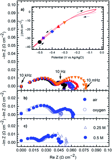
The oxygen reduction reaction fueling the formation of the products was studied on the GDE. Fig. 4 shows the cyclic voltammetry (CV) and impedance (EIS) results registered under the steady-state polarization conditions (time > 30 min). The ORR reaction was studied from a potential of −0.3 VAg/AgCl to −0.5 VAg/AgCl.
The impedance spectra show two Gerischer-like semicircles26 with a high-frequency linear segment. The high-frequency semi-circle is independent of the applied potential (Fig. 3a), oxygen supply (Fig. 3b), or electrolyte resistance (Fig. 3c). At frequencies between 10 kHz and 100 Hz, this is attributed to the electrode geometry, a behavior characteristic of semi-infinite pores.26,27 High-frequency signals may fail to penetrate the entire depth of the pores, leading to the straight line in the first part of the spectra. The low frequency semicircle exhibits similar characteristics, but with impedance magnitudes depending on all the previously mentioned parameters. Increasingly negative potentials, higher oxygen supply, and higher electrolyte concentration, all reduce the overall magnitude of the impedance. Similar behavior is seen in other triple-phase boundary reactions in gas diffusion electrodes,28 suggesting a mechanism that depends on the diffusion through deep electrode pores and adsorption of the reactive species (oxygen) before charge transfer occurs and the reaction products ((1) and (2)) diffuse out of the electrode to start the precipitation process (reaction 3). Indeed, Gerischer-like elements relate to chemical reactions in the bulk electrolyte preceding or following a finite diffusion phenomenon associated with an electrochemical reaction.
Thus, GDEx is defined as the reactive precipitation of intermediaries issued from the ORR at the GDE, with the metal precursors provided. Notably, the synthesis of nanostructures (as explained in the subsequent sections) is fast under the operational conditions here employed, with rates approaching ∼2.6 to 7 mg min−1. This implies ∼3.7 to 10 g per day using a single, inexpensive, electrochemical milireactor under flow regime, which can be scaled-up by replication. The process is highly reproducible, and it involves mild synthetic conditions (e.g., room temperature and atmospheric pressure). Also, the process entails low energy consumption, e.g., ∼2 to 6 mW per h per mg of nanomaterials formed. Finally, it is efficient, i.e., 50% current efficiency for the formation of the reactive intermediaries that fully react with the metal precursors to achieve the targeted nanostructures. As it operates in a flow-cell configuration, it is easily up-scalable by stacking multiple individual cells, without losing in performance. GDEx is a sustainable synthesis method for nanostructures because it uses the cleanest possible reagent, the electron, to fabricate in situ the chemicals needed to react with the metal precursors. It could be optimized for zero-waste generation. It is highly versatile, as a variety of nanostructures are feasible,29 besides providing an elegant and simple way to control many essential nanostructure attributes in the course of the synthesis. Albeit its early stage of development and broad possibilities for optimization, GDEx emerges as a ground-breaking synthesis method for comprehensive libraries of diverse nanostructures.
Charge driven structure control
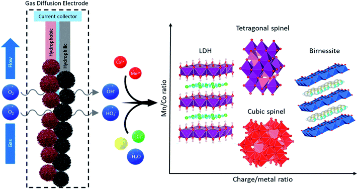
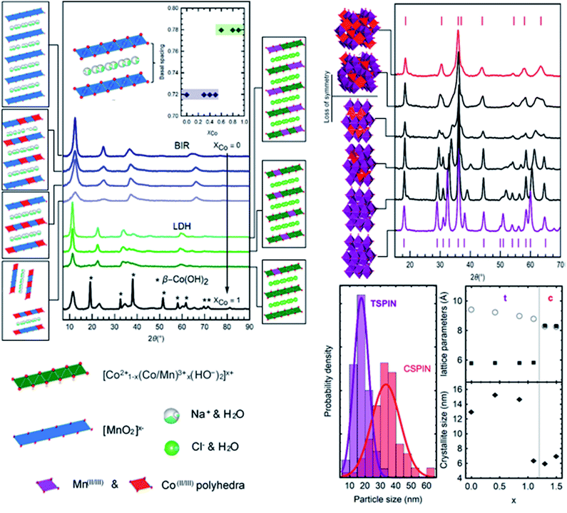
Control over the synthesized materials is easily exerted via the amount of charge applied and changes in the precursor solution. The ratio of charge applied to total metal concentration, RQ = Q/[M], as well as the mole fraction of Co, ΧCo = [Co]/([Co] + [Mn]), determines unique combinations of structure and composition of the products. Fig. 5 shows the structural transitions upon changing RQ and XCo. As the potential, and thus the charge applied, are constant in all the experiments presented, the rate of production of reactive oxygen species (ROS) is the same for all cases. These species (peroxide, hydroperoxyl, etc.) oxidize the metals from 2+ to the target average oxidation state required for each material. RQ is then controlled by changing the inlet metal precursor concentration, which leads to the desired oxidation state in the products. A higher ratio results in higher average valence of the synthesized materials, with common average oxidation states of the metals: CoMn-LDHs (LDH) +2.3 (reaction (6)), Bir-MnO2 (BIR) +3.7 (reaction (4)), and spinels (cubic CSPIN and tetragonal TSPIN) +2.66 (reaction (5)).30–32 The specific synthesis rates for these products are ∼7.0 mg min−1 for the LDHs, ∼4.5 mg min−1 for the SPINs, and 2.6 mg min−1 for the BIRs, respectively. The layered materials result from both extremes of RQ, as the layers can have a majority composition of either Mn(IV)O2 or Mn(II)(OH)2, while intermediate oxidation states yield spinels. The proposed formation reactions, starting from the dioxide described by reaction (3), are summarized:| MnO2(s) + dX2+(aq) + 2dNa+(aq) + 4dOH−(aq) → Na2dXdMnO2.2d(s) + 2dH2O(l) | (4) |
| MnO2(s) + 2X2+(aq) + 4OH−(aq) → X2MnO4(s) + 2H2O(l) | (5) |
| MnO2(s) + dX2+(aq) + dOH−(aq) + dCl−(aq) + dH2O(l) → XdMn(OH)3dCld(s) | (6) |
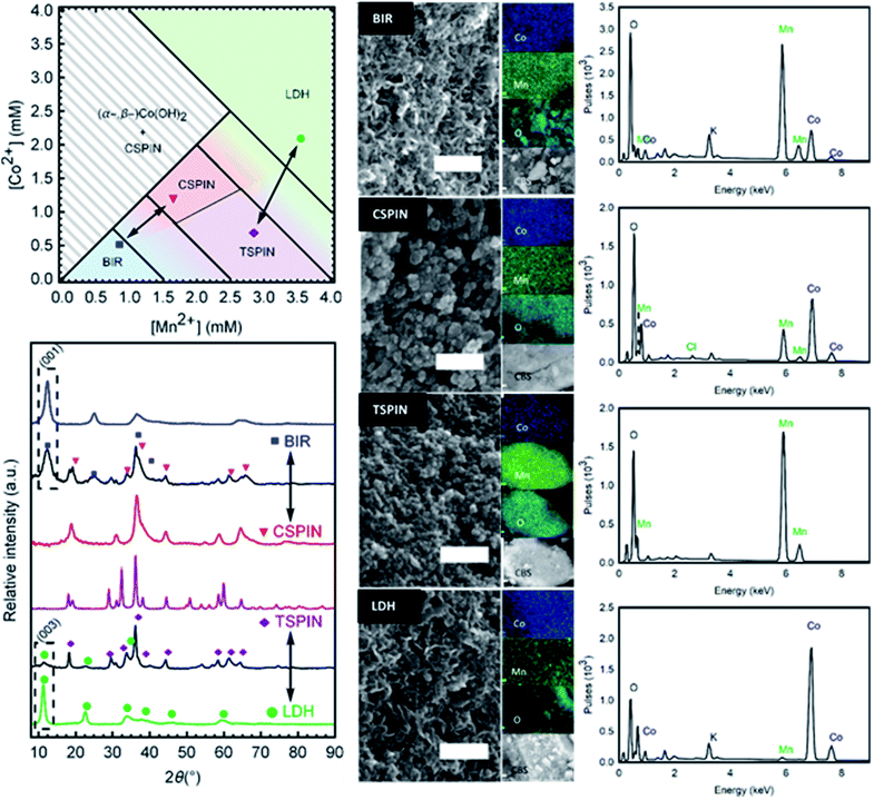
A phase diagram (Fig. 6 left) was composed from experiments carried out with −30 mA cm−2. The phase diagram reflects the predominant structure (or mixture) formed by using the annotated concentration of Co and Mn in the inlet solution to the gas diffusion cell. These results are also dependent on the volumetric flow rate (residence time) and the current drawn. As such, in order to reduce the degrees of freedom, the flow rate and current were fixed. Then the two main variables become each metal concentration; choosing a combination of them results in one of the 4 structural groups specified (birnessite, cubic spinel, tetragonal spinel, layered double hydroxide) or a mixture of them. Each structure has a certain tolerance for defects; once this threshold is overcome, a new phase is formed. This is reflected by the transition zones in the phase diagram with the mixture of colors. Once the metals (and their oxidation states) are in the right ratio for a new single phase product, they enter a new region of the phase diagram. So it becomes an important operational tool in order to predict the materials formed.
Mn-only containing solutions produced birnessites at concentrations lower than 1.5 mM, and single-phase spinels at [Mn] > 2.5 mM. Higher feed concentrations produced unstable Mn(OH)2, which quickly oxidized to the spinel, and resulted in leftover Mn2+ ions in solution, due to insufficient charge for precipitation. Values between the boundaries resulted in mixed compounds with both phases present. The addition of cobalt introduced a new degree of freedom. Stoichiometry changes reflecting the inlet solution occurred until the structural distortions cause too much strain, leading to the formation of a new phase, hence the formation of the cubic spinels (CSPIN) and LDHs. At preponderant cobalt fractions, β-hydroxides were formed; not long after production, the structure partially shifted to the α-variety, making the synthesis of single-phase β-Co(OH)2 difficult.
Birnessite-type layered Mn dioxide is rarely formed in the absence of small intercalating cations.33 As such, the large excess of Na+ (0.5 M) in the background electrolyte promoted its formation. In addition, the mildly oxidative nature of the synthesis conditions favored the birnessite structure as well, the MnO2 layers are relatively under-oxidized and electrostatically compensated by the intercalated cations, in contrast to other Mn dioxides (α-, β-, etc.) which include a higher Mn4+ content. This resulted in Na-birnessite, NaxMnO2. On the opposite end of the spectrum, the excess of Cl− in solution allowed the formation of the LDHs over single metal hydroxides when the RQ is low and the metals are mostly unoxidized. The β-Co(OH)2 structure was stabilized in the presence of Mn3+, forming the Cl− LDH.
Single- and multi-phase materials were obtained by operating in the specified concentration regions. Diffractograms of each area in the phase diagram are presented in Fig. 6 (bottom left). Characteristic peaks are marked for each structure, to show the phase purity of BIR, CSPIN, TSPIN, and LDH materials, as well as the different phase mixtures of the phase transitions. All peaks can be indexed by the respective phase. The tetragonal spinel shown was refined to the I41/amd space group. Peak broadening is observed for the cubic spinel (Fd![[3 with combining macron]](https://www.rsc.org/images/entities/char_0033_0304.gif) m), attributed to the (nano-)crystallite size. The BIR and LDH traces are also shown to be phase pure. The shift to small angles in the reflections of the LDH, relative to the BIR, serves as an easy identifier of the hydrotalcite structure. Peak splitting around 65° 2θ, seen as a broad hump in the BIR spectra, points to an orthorhombic structure, as opposed to the naturally occurring hexagonal birnessite. The peak broadness, present in the LDH pattern to a lesser degree, is a feature of turbostratic structures.34
m), attributed to the (nano-)crystallite size. The BIR and LDH traces are also shown to be phase pure. The shift to small angles in the reflections of the LDH, relative to the BIR, serves as an easy identifier of the hydrotalcite structure. Peak splitting around 65° 2θ, seen as a broad hump in the BIR spectra, points to an orthorhombic structure, as opposed to the naturally occurring hexagonal birnessite. The peak broadness, present in the LDH pattern to a lesser degree, is a feature of turbostratic structures.34
Micrographs to examine the morphology and dimensions of samples from each structure are shown in Fig. 6 (center). Clear distinctions can be made between spinel and layered materials. Spinels exhibit broadly jagged spheres of 15 nm to 35 nm in diameter. Meanwhile, the layered materials can be seen as delaminated sheets, characteristic of turbostratic birnessite,35 with face dimensions in the range of 50 nm. Brunauer–Emmett–Teller (BET) analysis for the specific surface area of the as-prepared powders resulted in very large values, greater than 70 m2 g−1 for all materials synthesized. Particle sizes estimated from the surface area (approx. 30 nm in diameter) correspond with the range of sizes seen in the micrographs. The large surface area is a feature of the low temperature used to synthesize the materials, as traditional high-temperature processes yield larger, and more inactive, particles.10,14 Next to each micrograph in Fig. 6 are EDS images showing the elemental composition of the samples, as well as the CBS (circular backscatter detector) image of the region analyzed from each material. The spectra with the approximate elemental ratios are shown in Fig. 5 (right). The composition from the EDS is in agreement with the metal composition of the solution fed to the cell. As the removal of the metals from solution nears 100%, as measured by ICP-OES, the chemical composition of the particles mirrors that of the initial solution. The removal data, as well as the EDS results, were corroborated by the ICP-OES analysis of the (acid digested) products. Table 1 shows the composition ranges associated with the structures shown.
| Structure abbreviation | Boundary compositions | Sample shown in Fig. 5 | |
|---|---|---|---|
| Low Co | High Co | ||
| BIR | NaxMnO2 | NaxMn0.5Co0.5O2 | NaxMn0.8Co0.2O2 |
| TSPIN | Mn3O4 | Co1.1Mn1.9O4 | Mn3O4 |
| CSPIN | Co1.2Mn1.8O4 | Co3O4 | Co1.8Mn1.2O4 |
| LDH | Co0.6Mn0.4(OH)2Cl0.4 | Co0.9Mn0.1(OH)2Cl0.9 | Co0.9Mn0.1(OH)2Cl0.9 |
Structural transformations via doping
The Co/Mn ratio fed to the flow cell is reflected in the final product, as >99% of the metal ions are removed from solution when the total metal concentration is kept below 4.5 mM. For this reason, GDEx can also be regarded as an effective method to remove metal ions from solution (i.e., for remediation or metal recovery purposes).Cobalt doping can substitute Mn sites (such as for birnessites and LDHs, Fig. 7 left),7 or it can change the structure as is the case with the spinels14 (Fig. 7 right).
Fig. 7 shows the traces of the layered materials, from pure Na-birnessite to a hydrotalcite phase for the LDHs, and the β-Co(OH)2. All mixed-metal compounds are single phase. As previously mentioned, the Mn-only birnessite exhibits orthorhombic character. Co-doping in birnessites is shown here to decrease interlayer ordering (c-axis) as evidenced by the reduced intensity for (001) and (002) peaks (approx. 12° and 23° 2θ respectively) but otherwise preserves the sheet structure. The peaks at larger angles (approx. 37° and 68° 2θ respectively) with no c-axis contribution show the conservation of the sheet integrity regardless of interlayer c-stacking. The reduced d-space ratio (Mn: 1.68 to MnCo: 1.72) between the (11,20) and (31,02) peaks suggests that Co-doping under these conditions shifts the structure from orthorhombic to hexagonal birnessite.36 At the same time, even with increased Co-doping the basal spacing was conserved around 7.3 Å. The addition of lower valent cations (Co2+/Co3+vs. Mn3+/Mn4+) is balanced by the presence of Na+ in the interlayer to electrostatically stabilize the structure, causing an expansion to accommodate the ions. The addition of more Co (above XCo = 0.5) resulted in mixed-phase compounds. Larger deviations in the average valence of the metals (Co/Mn) in the nanosheets, as well as the size constraints, disrupt the sheet ordering to the point where unstable delaminated sheets undergo transition into spinels.
The mixture of hydroxides presented in the bottom trace of Fig. 7 (left) is the result of a partial transformation occurring during the collection and cleaning process (post-synthesis) due to the instability of the β-hydroxide structure. The addition of Mn proved effective in stabilizing it, resulting in the layered double hydroxides. Relative to the birnessites, the expansion of the basal spacing continues with the formation of the hydroxides (Fig. 7). Layers of positively charged Mn/Co hydroxides, [(x2+)1−d(Mn3+)d(OH)2]d+, are balanced by Cl− ions in the interlayer spacing. The (003) peak at 11.26° 2θ is used to calculate the basal thickness, here 7.9 Å on average. LDHs were produced and stabilized with XCo between 0.50 and 0.90. Low amounts of Co produced a phase mixture with spinels. As such, Na-birnessites were produced with XCo = 0 to 0.5, LDHs with XCo = 0.5 to 0.9.
Tetragonal–cubic spinel transitions
Heavy cobalt loading (Co/(Co + Mn) > 0.4) results in cubic spinels (Fd3m). Increasing amounts of Mn (Co/(Co + Mn) < 0.4) creates lattice distortions due to the Jahn–Teller effect, resulting in a clear shift lowering the symmetry to the tetragonal structure (I41/amd).10 There are two kinds of transitions seen in Fig. 7, characterized by the diffractograms and the lattice parameter. A sharp cubic–tetragonal transition is expected and seen at (Co/(Co + Mn) > 0.4) with the a/b/c lattice parameter of 8.3 Å splitting into a/b = 5.8 Å and c = 8.81 Å. Within each phase, gradual transition towards the inflection point in the lattice fitting is seen with varying Co/Mn ratio. The symmetry lowering is clearly observed from the splitting of the Fd3m peaks as the Co content decreases, accompanied by an expansion of the c-lattice parameter from 8.81 Å for Co0.8Mn2.2O4 to 9.43 Å for pure Mn3O4. This shows remarkable control of the composition and structure of the particles produced in the entire range of CoxMn3−xO4 studied.All samples are nanocrystalline. The samples heaviest in Co (Co/(Co + Mn) > 0.4) exhibit crystallite sizes in the order of 7 nm, while lower Co content produces more crystalline samples up to the 15 nm range as determined by the Scherrer equation. The latter samples were collected as single crystals of the same 15 nm average size (Fig. 6, bottom left), while the smaller cubic crystallites form polycrystalline particles of 35 nm with a broader dispersion. Using only Co to produce the c-spinel Co3O4 proved unsuccessful as the Co remained under-oxidized by the ROS produced at the electrode, and a phase mixture with hydroxides formed instead of the pure Co3O4. To summarize, two sets of nanoparticles are produced, smaller single crystal particles of approximately 15 nm in diameter composed of tetragonal CoxMn3−xO4 (x < 1), and larger particles of 35 nm composed of 6 nm crystallites of cubic CoxMn3−xO4 (x > 1).
Electrochemical applications
| Structure | Co/(Co + Mn) | η10 (mV) | η100 (mV) | Tafel slope (mV dec−1) |
|---|---|---|---|---|
| TSPIN | 0 | 410 | — | 46 |
| CSPIN | 0.5 | 375 | 485 | 43 |
| BIR | 0.25 | 375 | — | 53 |
| LDH | 0.5 | 355 | 420 | 47 |
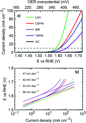
With overpotentials of 355 mV and 420 mV for 10 mA cm−2 and 100 mA cm−2 respectively, the LDH sample outperformed all materials tested. The low overpotentials and the low Tafel slope compare favorably with the literature and generally match or sometimes outperform most Co or Mn based metal oxide catalysts and bulk LDHs on GCE or similar substrates.37 Table ESI-1† shows a collection of state of the art materials of Co and Mn with similar structures for comparison. Within each structural group, the samples synthesized here exhibit promising performance. Among the spinels, the cubic structure performed far better than the tetragonal sample. The tetragonal structure tested was pure Mn3O4. Here the addition of 50% Co, and as a consequence, the transition to the cubic structure reduces the overpotential at 10 mA cm−2 by 35 mV with outstanding performance and better metrics than the bulk of mixed metal spinels in the literature.37
It is worth noting that the TSPIN sample contained the smaller particles, with approximately 15 nm in diameter (via SEM), as opposed to the 35 nm for the CSPIN sample. Smaller particle sizes improve the catalysis due to the larger surface area. However, the presence of cobalt, together with the structural change it induces, produces better catalytic properties despite the larger particle size of the cubic spinels. The CSPIN and LDH were both made with the same Mn/Co elemental ratio. The sheet-like structure of the LDH played a key role in making a more active material. LDH nanosheets have been shown to possess outstanding OER electrocatalytic properties due to the large active area given by the morphology, and the highly defective mixed-valence structure. At the same time, the BIR nanosheets containing half the amount of cobalt performed similarly to the cobalt-rich CSPIN, with the same η10 but a slightly higher Tafel slope.
Conclusions
The level of control achieved over structure and composition with a single system can open the door to the systematic creation of libraries of materials to develop, for instance, better electrocatalysts. The technique presented, GDEx, offers materials with a wide range of structures, compositions, and sizes, with controlled properties, synthesized in the same environment with minimal chemical addition, making it a landmark tool to exploit in material design. The nature of the reactor allows for one set of conditions to be used, and merely changing the inlet solution, to produce the target structure, all with a highly scalable configuration. To summarize, the materials synthesized and discussed include birnessites with Co doping of up to 40% of the Mn sites, tetragonal and cubic mixed Co/Mn spinels with fine control over the structural distortions and transitions, layered Co hydroxides, and CoMn-layered double hydroxides. All these exhibited nanocrystallites, as well as particle sizes down to 15 nm, both for single crystals and polycrystalline particles. In future studies, the elements (i.e., metal ion precursors) can be swapped by other elements of interest (Ni, Fe), and tertiary mixtures could be as easily achieved. Finally, birnessites, cubic spinels, and layered double hydroxides were tested for OER catalysis, and each exhibited at least state-of-the-art catalytic properties.Partial conclusions can be drawn to emphasize the benefit of the systematic material synthesis employed here. Both layered compounds outperformed the spinel materials made of similar metal compositions. At the same time, within each structural family, the addition of cobalt improved the performance significantly. In this way, structure–property relationships can begin to be built across structures and compositions with a single synthesis process. By fixing the charge applied and residence time in the flow cell, the total metal concentration and Co/Mn ratio can be varied and directly result in a range of materials to optimize. Once the structure and composition result in the desired properties, further degrees of freedom can be added by varying the volumetric flow rate and current, to achieve control over other parameters such as particle or crystallite size. The choice of supporting electrolyte can also be chosen to modulate the basal spacing in the layered materials, as the cations (Na+) or anions (Cl−) find themselves intercalated between the layers. The choice of larger ions (e.g.: Cs+, NO3−) can result in enlarged interlayer distances, which are a factor in electrocatalytic performance. Above all, GDEx emerges as a sustainable synthesis method for vast libraries of functional nanostructures.
Conflicts of interest
There are no conflicts to declare.Acknowledgements
RP acknowledges VITO Strategic PhD grant funding no. 1510774. RP, GP, JF, and XDB thank the support from the Flemish SIM MaRes programme, under grant agreement no. 150626 (Get-A-Met project). XDB and JF thank the funding from the European Union's Horizon 2020 research and innovation programme under grant agreement no. 654100 (CHPM2030 project). G. Pozo acknowledges the funding from the European Union's Horizon 2020 research and innovation programme MSCA-IF-2017, under grant agreement no. 796320 (MAGDEx: Unmet MAGnetic properties in micro and nano-particles by synthesis through gas diffusion electrocrystallisation (GDEx).References
- L. Chen, P. Fleming, V. Morris, J. D. Holmes and M. A. Morris, Size-related lattice parameter changes and surface defects in ceria nanocrystals, J. Phys. Chem. C, 2010, 114(30), 12909–12919 CrossRef CAS.
- A. A. Gewirth and M. S. Thorum, Electroreduction of dioxygen for fuel-cell applications: materials and challenges, Inorg. Chem., 2010, 49, 3557–3566 CrossRef CAS PubMed.
- M. Winter and R. J. Brodd, ACS Publications, 2004 CrossRef CAS; M. Warshay and P. R. Prokopius, J. Power Sources, 1990, 29, 193 CrossRef CAS.
- A. J. Bard and M. A. Fox, Artificial photosynthesis: solar splitting of water to hydrogen and oxygen, Acc. Chem. Res., 1995, 28, 141–145 CrossRef CAS.
- S. Trasatti, Electrodes of Conductive Metallic Oxides, Elsevier Scientific Software, 1980, vol. 2 Search PubMed.
- Y. Liang, et al., Co3O4 nanocrystals on graphene as a synergistic catalyst for oxygen reduction reaction, Nat. Mater., 2011, 10, 780, DOI:10.1038/nmat3087.
- E. A. Johnson and J. E. Post, Water in the interlayer region of birnessite: Importance in cation exchange and structural stability, Am. Mineral., 2006, 91, 609–618 CrossRef CAS.
- K. W. Nam, et al., The high performance of crystal water containing manganese birnessite cathodes for magnesium batteries, Nano Lett., 2015, 15, 4071–4079 CrossRef CAS PubMed.
- L. Xie, et al., Cox Ni1−x double hydroxide nanoparticles with ultrahigh specific capacitances as supercapacitor electrode materials, Electrochim. Acta, 2012, 78, 205–211 CrossRef CAS.
- F. Cheng, et al., Rapid room-temperature synthesis of nanocrystalline spinels as oxygen reduction and evolution electrocatalysts, Nat. Chem., 2011, 3, 79 CrossRef CAS PubMed.
- L. Zhou, D. Zhao and X. W. Lou, Double-shelled CoMn2O4 hollow microcubes as high-capacity anodes for lithium-ion batteries, Adv. Mater., 2012, 24, 745–748 CrossRef CAS PubMed.
- Y. Liang, et al., Covalent hybrid of spinel manganese–cobalt oxide and graphene as advanced oxygen reduction electrocatalysts, J. Am. Chem. Soc., 2012, 134, 3517–3523 CrossRef CAS PubMed.
- P. Lavela, J. Tirado and C. Vidal-Abarca, Sol–gel preparation of cobalt manganese mixed oxides for their use as electrode materials in lithium cells, Electrochim. Acta, 2007, 52, 7986–7995 CrossRef CAS.
- C. Li, et al., Phase and composition controllable synthesis of cobalt manganese spinel nanoparticles towards efficient oxygen electrocatalysis, Nat. Commun., 2015, 6, 7345 CrossRef CAS PubMed.
- K. Kai, et al., Room-temperature synthesis of manganese oxide monosheets, J. Am. Chem. Soc., 2008, 130, 15938–15943 CrossRef CAS PubMed.
- F. Song and X. Hu, Ultrathin cobalt–manganese layered double hydroxide is an efficient oxygen evolution catalyst, J. Am. Chem. Soc., 2014, 136, 16481–16484 CrossRef CAS PubMed.
- I. Katsounaros, S. Cherevko, A. R. Zeradjanin and K. J. Mayrhofer, Oxygen electrochemistry as a cornerstone for sustainable energy conversion, Angew. Chem., Int. Ed., 2014, 53, 102–121 CrossRef CAS PubMed.
- F. Cheng and J. Chen, Metal–air batteries: from oxygen reduction electrochemistry to cathode catalysts, Chem. Soc. Rev., 2012, 41, 2172–2192 RSC.
- Y. Alvarez-Gallego, X. Dominguez-Benetton, D. Pant, L. Diels, K. Vanbroekhoven, I. Genné and P. Vermeiren, Development of gas diffusion electrodes for cogeneration of chemicals and electricity, Electrochim. Acta, 2012, 82, 415–426 CrossRef CAS.
- H. H. Yang and R. L. McCreery, Elucidation of the mechanism of dioxygen reduction on metal-free carbon electrodes, J. Electrochem. Soc., 2000, 147(9), 3420–3428 CrossRef CAS.
- G. Pozo, P. de la Presa, R. Prato, I. Morales, P. Marin, J. Fransaer and X. Dominguez-Benetton, Spin transition nanoparticles made electrochemically, Nanoscale, 2020, 12(9), 5412–5421 RSC.
- R. C. B. Castillo, A. Garcia-Mendoza, Y. Alvarez-Gallego, J. Fransaer, M. Sillanpää and X. Dominguez-Benetton, pH Transitions and electrochemical behavior during the synthesis of iron oxide nanoparticles with gas-diffusion electrodes, Nanoscale Adv., 2020 Search PubMed.
- S. G. Eggermont, A. Rua-Ibarz, K. Tirez, X. Dominguez-Benetton and J. Fransaer, Oxidation-assisted alkaline precipitation: the effect of H2O2 on the size of CuO and FeOOH nanoparticles, RSC Adv., 2019, 9(51), 29902–29908 RSC.
- L. C. Weng, A. T. Bell and A. Z. Weber, Modeling gas-diffusion electrodes for CO2 reduction, Phys. Chem. Chem. Phys., 2018, 20(25), 16973–16984 RSC.
- H. H. Yang and R. L. McCreery, Elucidation of the Mechanism of Dioxygen Reduction on Metal-Free Carbon Electrodes, J. Electrochem. Soc., 2000, 147, 3420–3428 CrossRef CAS.
- A. Lasia, Modeling of Impedance of Porous Electrodes, 2009, vol. 43 Search PubMed.
- C. Hitz and A. Lasia, Experimental study and modeling of impedance of the her on porous Ni electrodes, J. Electroanal. Chem., 2001, 500, 213–222 CrossRef CAS.
- A. Dhanda, H. Pitsch and R. O'Hayre, Diffusion Impedance Element Model for the Triple Phase Boundary, J. Electrochem. Soc., 2011, 158, B877–B884 CrossRef CAS.
- R. A. Prato, V. Van Vught, S. Eggermont, G. Pozo, P. Marin, J. Fransaer and X. Dominguez-Benetton, Gas Diffusion Electrodes on the Electrosynthesis of Controllable Iron Oxide Nanoparticles, Sci. Rep., 2019, 9(1), 1–11 CrossRef CAS PubMed.
- J. E. Post and D. R. Veblen, Crystal structure determinations of synthetic sodium, magnesium, and potassium birnessite using TEM and the Rietveld method, Am. Mineral., 1990, 75, 477–489 CAS.
- J. Molenda, et al., The effect of 3d substitutions in the manganese sublattice on the charge transport mechanism and electrochemical properties of manganese spinel, Solid State Ionics, 2004, 171, 215–227, DOI:10.1016/j.ssi.2004.04.022.
- J. Zhao, et al., CoMn-layered double hydroxide nanowalls supported on carbon fibers for high-performance flexible energy storage devices, J. Mater. Chem. A, 2013, 1, 8836–8843 RSC.
- S. Ching, D. J. Petrovay, M. L. Jorgensen and S. L. Suib, Sol−Gel Synthesis of Layered Birnessite-Type Manganese Oxides, Inorg. Chem., 1997, 36, 883–890, DOI:10.1021/ic961088d.
- V. A. Drits, B. Lanson and A.-C. Gaillot, Birnessite polytype systematics and identification by powder X-ray diffraction, Am. Mineral., 2007, 92, 771–788, DOI:10.2138/am.2007.2207.
- Z. Qin, et al., Local structure of Cu2+ in Cu-doped hexagonal turbostratic birnessite and Cu2+ stability under acid treatment, Chem. Geol., 2017, 466, 512–523, DOI:10.1016/j.chemgeo.2017.06.040.
- H. Zhao, et al., Redox reactions between Mn (II) and hexagonal birnessite change its layer symmetry, Environ. Sci. Technol., 2016, 50, 1750–1758 CrossRef CAS PubMed.
- J. S. Kim, B. Kim, H. Kim and K. Kang, Recent progress on multimetal oxide catalysts for the oxygen evolution reaction, Adv. Energy Mater., 2018, 8(11), 1702774 CrossRef.
- Y. Li, X. Feng, S. Cui, Q. Shi, L. Mi and W. Chen, From α-NaMnO2 to crystal water containing Na-birnessite: enhanced cycling stability for sodium-ion batteries, CrystEngComm, 2016, 18(17), 3136–3141 RSC.
- F. Gálvez, M. Cabello, P. Lavela, G. F. Ortiz and J. L. Tirado, Sustainable and Environmentally Friendly Na and Mg Aqueous Hybrid Batteries Using Na and K Birnessites, Molecules, 2020, 25(4), 924 CrossRef PubMed.
- B. Lin, X. Zhu, L. Fang, X. Liu, S. Li, T. Zhai and H. Xia, Birnessite Nanosheet Arrays with High K Content as a High-Capacity and Ultrastable Cathode for K-Ion Batteries, Adv. Mater., 2019, 31(24), 1900060 CrossRef PubMed.
- J. H. Jo, J. Y. Hwang, J. Choi, Y. K. Sun and S. T. Myung, Layered K0.28MnO2⋅0.15H2O as a Cathode Material for Potassium-Ion Intercalation, ACS Appl. Mater. Interfaces, 2019, 11(46), 43312–43319 CrossRef CAS PubMed.
Footnote |
| † Electronic supplementary information (ESI) available. See DOI: 10.1039/d0ta00633e |
| This journal is © The Royal Society of Chemistry 2020 |

