
 Open Access Article
 This Open Access Article is licensed under a
 Creative Commons Attribution 3.0 Unported Licence
The natural critical current density limit for Li7La3Zr2O12 garnets†
Florian
Flatscher
a,
Martin
Philipp
a,
Steffen
Ganschow
b,
H. Martin R.
Wilkening
 a and
Daniel
Rettenwander
*a
a and
Daniel
Rettenwander
*a
aGraz University of Technology, Institute of Chemistry and Technology of Materials (NAWI Graz), 8010 Graz, Austria. E-mail: rettenwander@tugraz.at
bLeibniz-Institut für Kristallzüchtung, 12489 Berlin, Germany
First published on 9th March 2020
Abstract
Ceramic batteries equipped with Li-metal anodes are expected to double the energy density of conventional Li-ion batteries. Besides high energy densities, also high power is needed when batteries have to be developed for electric vehicles. Practically speaking, so-called critical current densities (CCD) higher than 3 mA cm−2 are needed to realize such systems. As yet, this value has, however, not been achieved for garnet-type Li7La3Zr2O12 (LLZO) being one of the most promising ceramic electrolytes. Most likely, CCD values are influenced by the area specific resistance (ASR) governing ionic transport across the Li|electrolyte interface. Here, single crystals of LLZO with adjusted ASR are used to quantify this relationship in a systematic manner. It turned out that CCD values exponentially decrease with increasing ASR. The highest obtained CCD value was as high as 280 μA cm−2. This value should be regarded as the room-temperature limit for LLZO when no external pressure is applied. Concluding, for polycrystalline samples either stack pressure or a significant increase of the interfacial area is needed to reach current densities equal or higher than the above-mentioned target value.
Introduction
Li metal batteries, which take advantage of ceramic electrolytes, are considered promising next-generation energy storage systems that are expected to achieve practical energy densities as high as 500 W h kg−1, which is considerably larger than those of conventional lithium-ion battery concepts with liquid electrolytes. At the same time, ceramic electrolytes, being non-flammable at room temperature, will significantly enhance the safety of such batteries.1 In the ideal case such cells pave the way for safe electric vehicles offering a driving range of up to 700 km with respect to a single charging process. This range corresponds to an increase of the driving distance by more than 100% compared to conventional systems.2 Despite of high energy density also high power is needed to realize the next generation of electric cars; preferably, current densities should at least reach values as a high as 3 mA cm−2.3By now, the most promising ceramic electrolyte showing both a high Li-ion conductivity and a good stability when in contact with Li metal is garnet-type cubic Li7La3Zr2O12 (LLZO) including its variants.4–6 The highest critical current density value (CCD), that is, the maximum applicable current density without short circuiting, which has been reported for LLZO so far, is, however, in the range of several hundreds of μA cm−2 at room temperature. This range corresponds to samples tested without applying external pressure, excluding porous LLZO interfaces.7,8 Unfortunately, these values are still too low for battery applications.
Recently, it has been shown that the self-diffusion coefficient of metallic Li plays a prominent role with respect to the CCD.9–11 At high current densities, the Li+ flux toward the interface greatly exceed the flux of Li0 away from the interface because of diffusion, creep, and hydrostatic compression.9–12 Hence, pores will form at the interface leading to severe constrictions in current and, finally, cause short circuits of the system.9–11 It has been suggested that the formation of such pores can be delayed (i) by applying an external pressure or (ii) by increasing the temperature of the system. The latter will affect properties such as plastic deformation of lithium metal and, moreover, lead to increased Li diffusivity and creep, respectively.9,10,12–14 Moreover, it is proposed that a low interfacial resistance may also plays an important role to realize high CCD values.14,15 A systematic study on the interplay of the area specific resistance (ASR) and the CCD is, however, still missing.
This circumstance is related to the fact that such a comparison is by far not straightforward considering the large set of parameters that may affect both the ASR and, thus, the CCD values. In detail, the ASR is greatly influenced by Li2CO3 formation in humid atmosphere,16,17 interface coatings, such as Al2O3,18 Si,19 ZnO,20 and Au,8 cleaning of the surface and heat treatments21 as well as the pressure applied during testing.10,21 On the other hand, critical current densities are largely affected by the kind of grain boundaries present, the distribution of grain sizes, porosity, and the size of surface flaws.7,9,15,22–24
Fortunately, use of single crystals allows that many of these influencing variables can be eliminated. Since single crystals have no grain boundaries, they are 100% dense and show a minimum of surface defects as compared to polycrystalline samples. As they can easily be prepared with high chemical homogeneity, no sample-to-sample variations or variations in composition on the μm scale are expected to influence the results.
Here, cubic LLZO single crystals (namely Li6.4Ga0.2La3Zr2O12) are used as model system throughout all experiments, thus reducing the number of parameter space affecting interfacial resistances and current densities significantly. The later parameters were extracted from impedance spectroscopy and galvanostatic cycling experiments. In the present study, we systematically modified the surface of the single crystals, that is, we varied the ASR values characterizing the Li|LLZO interface, to determine critical current densities as a function of the ASR. This approach allowed us to precisely determine the interrelation of the ASR and the CCD as well as the upper current density limit in Li-metal cells equipped with LLZO. Noteworthy, our results refer to room temperature and were collected without having applied any external pressure.
Experimental
Growth of the single crystals
Single crystalline Li6.4Ga0.2La3Zr2O12 were directly grown from the melt by the Czochralski method. Li2CO3 (99% Merck), La2O3 (99.99%, Aldrich), Ga2O3 (99.0%, Aldrich) and ZrO2 (99.0%, Aldrich) were dried and subsequently used as reagents for the synthesis. A stoichiometric mixture with an excess of 10 wt% Li2CO3 was uniaxially pressed into pellets and annealed at 1123 K for 4 h. The heating rate was set to 5 K per minute. Afterwards, the sintered pellet was melted in an inductively heated iridium crucible that was combined with a 25 kW microwave generator. In inert nitrogen atmosphere, the crystal was pulled from the melt at constant rotation and speed viz. at 10 rpm and 1.5 mm h−1, respectively. The single crystals with respect to structure, composition, Li ion conductivity can be found elsewhere.25Systematic adjustment of the ASR and cell assembling
The single crystal was cut into 1 mm thick discs perpendicular to the direction of growth using a diamond saw. Those discs were first dry polished at a Struers LapPol 25 at 200 to 300 rpm with SiC grinding paper (220# to 4000#) to create parallel sides and to remove any residual surface layers of Li2CO3 and/or LiOH. After polishing, the samples were first scratched with a glasscutter and then broken to increase the number of samples. The single crystals were transferred into a glovebox filled with Ar to avoid any contact with humidity or air. The samples were put into a corundum crucible, placed into an oven located in the glovebox, and heated to 400 °C for 3 h. After heat treatment, the crystals were manually polished with SiC grinding paper (#1000 to #4000) to remove any degradation layers. Particular care was undertaken to treat all single crystals in a similar way, i.e., to minimize variations in surface defects. After the sample were let to cool down to room temperature, they were transferred back into the glove box. Then, Li metal electrodes were punched out with a diameter of 2.5 mm. The were placed on both sides of the crystal and covered with a copper current collector each.To prepare samples with different ASR the crystals were transferred to a vacuum line and heated to ensure a close contact between Li metal and LLZO electrolyte. Different heating temperatures and holding times were tested to change the interface impedance. A vacuum line was used to rule out any reaction with contaminants such as traces of CO2 or N2.
To perform the CCD tests, the samples were then placed into a custom-made heat resistant Swagelok-like cell. Great care was undertaken to avoid applying any external pressure. Therefore, impedance spectroscopy was used to check changes in the interfacial resistance during assembling to ensure quasi-zero pressure conditions.
Impedance spectroscopy
Broadband impedance measurements were performed directly in the Ar-filled glovebox using a Novocontrol Alpha analyser in combination with a ZGA interface. We measured the complex impedance as a function of frequency, which we varied from 1 MHz down to 100 mHz; the voltage amplitude was set to 10 mV.Galvanostatic cycling
Cells were cycled at constant current with a half cycle time of 20 min and a current increase after each cycle using a Keithley 2450 SMU galvanostat/potentiostat. The starting current density was 1 μA cm−2, which we systematically increased to 5 μA cm−2, 10 μA cm−2 and finally to 20 μA cm−2. Then, we further increased the current density in steps of 20 μA cm−2 until a short circuit occurred.Results and discussion
Area specific resistances
Broadband impedance data of symmetric Li|LLZO|Li cells were recorded at 20 °C under inert gas atmosphere (Ar). In general, if non-blocking metal electrodes are used, the corresponding Nyquist plots, which are obtained when the real part (ZRE) of the complex impedance is plotted vs. its imaginary part (−ZIM), are usually governed by two electrical relaxation processes. While the semicircle seen at high frequencies is assigned to electrical relaxation being typical for that taking place in the bulk, the onset or the full semicircle appearing at lower frequencies characterizes the electrolyte|electrode interface. In Fig. 1 the Nyquist plots of our study are shown. As an example, the location curve in Fig. 1d of a sample with an ASR value of 253 Ω cm2 can be parametrized with two R-CPE units each consisting of a resistor (R) connected in parallel to a so-called constant phase element (CPE). In general, the capacitance of the R|CPE units is given by C = (R1−nCPE)1/n, whereby n accounts for the unideal behavior of the capacitance.26 The semicircle at high frequency is characterized by capacitances in the order of C ≈ 3 pF and a relative permittivity εrel of approximately 50. These vales typically characterize electrical relaxation taking place in the grain interior.27 The corresponding bulk ionic conductivities σbulk are given by σbulk = 1/Rbulk(d/A) with A being the electrode area and d being the thickness.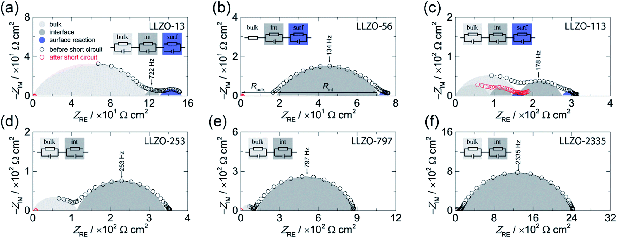 | ||
| Fig. 1 Complex plane plot before (black circles) and after (red circles) the short circuit event of the electrical impedance of symmetrical Li|LLZO|Li cells recorded at 20 °C. The area specific resistance (ASR) was systematically varied: (a) 13 Ω cm2, (b) 56 Ω cm2, (c) 113 Ω cm2, (d) 253 Ω cm2, (e) 797 Ω cm2, and (f) 2335 Ω cm.2 The equivalent circuits used to parameterize the impedance data are shown in the insets. | ||
Here, we obtain σbulk = 1 × 10⁻³ S cm−1 which is in perfect agreement with our earlier study on the bulk properties on Czochralski-grown single crystals, see also Table 1.25 We have to note that for LLZO-56 the bulk semicircle cannot be seen because of a noisy signal, which is not shown in the figure; the corresponding response has thus only be taken into account by a resistor R instead of a full R|CPE unit, see Fig. 1b.
| Cell | σ bulk/mS cm−1 | C bulk /pF cm−2 | ε bulk | p stack/MPa | ASR/Ω cm2 | C int /μF cm−2 | n | f int |
|---|---|---|---|---|---|---|---|---|
| a Calculated with C = (R1−nCPE)1/n. | ||||||||
| LLZO-13 | 1.3 | 3 | 50 | — | 13 | 0.1 | 0.8 | 722 |
| LLZO-56 | — | 56 | 2.0 | 0.6 | 134 | |||
| LLZO-118 | — | 116 | 0.9 | 0.6 | 178 | |||
| LLZO-253 | — | 253 | 1.7 | 0.7 | 92 | |||
| LLZO-797 | — | 797 | 5.6 | 0.7 | 28 | |||
| LLZO-2335 | — | 2335 | 1.6 | 0.7 | 34 | |||
Interestingly, the curves in Fig. 1a–c show an additional semicircle at even lower frequencies which is only seen for samples with low interfacial resistances, see Fig. 1a, for instance. Most likely, for samples with relatively high ASR values this process is masked by the dominant semicircle characterizing the electrolyte|electrode interface. Here, we used an additional R|CPE unit to take this low frequency process into account. As its capacitance turned out to be in the range of ≤10−5 F cm−2 we assume that it represents a surface reaction.26 Such an additional process has already been observed in earlier studies; it has been suggested that it is caused by an alloying reaction between the Au interlayer and Li metal.8 As in our case, no artificial interlayers are present, thus we think that it reflects an interfacial reaction between Li metal and LLZO. Most likely, it shows the formation of a thin passivating layer composed by the binaries Li2O, ZrO2, and La2O3.6
Coming back to the ASR values extracted from the Nyquist plots we have to note that it is known that the Li-ion kinetics at the Li|LLZO interface are limited by current constriction near the interface. Therefore, the resistance mainly originates from the volume directly below the contact points of Li metal on LLZO.10,28,29 Hence, the finding can be interpreted as spreading resistance; in the case of an intimate contact between Li and LLZO the interfacial resistance might become negligible.10,28 This consideration suggests that the magnitude of the ASR is related to the loss of contact points or to the extent of a non-uniform interface between the Li and LLZO. Insufficient contacts lead to constrictions in current distribution eventually causing high effective current densities, Ieff, which is given by the current applied multiplied with the area of contact points.
Critical current density
In Fig. 2 the results from galvanostatic cycling of the samples characterized in Fig. 1 are shown. At low current densities we observe ohmic behavior (region I).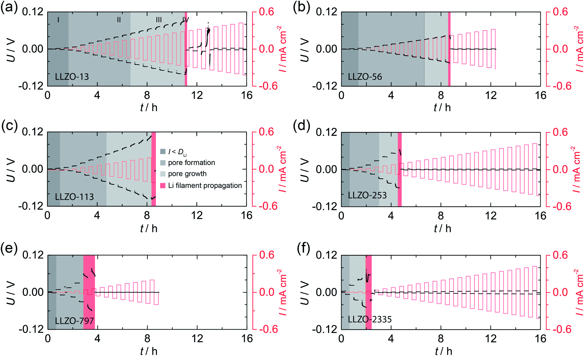 | ||
| Fig. 2 Galvanostatic cycling, that is, striping and plating experiments, of the symmetric Li|LLZO|Li cells studied in Fig. 1; measurements were carried out at room temperature (20 °C). U: voltage, I: current density. See text for further explanation. | ||
In this region, the applied current density does not exceed the vacancy diffusion limit in Li metal. We anticipate that no pores form and that the morphology of Li remains stable during platting and stripping.10 When going to higher current densities we recognize deviations from ohmic behavior (region II). In this region the current densities applied exceeds the diffusion limit in Li metal, vacancies are generated and accumulate at the interface where they form pores, possibly due to the faster diffusion of adatoms as compared to vacancies in the bulk.10,30 The formation of pores leads to an increasing Ieff and, hence, an increasing polarization, which remains constant afterwards (no pore growth). With increasing current densities the growth of pores starts, which leads to a morphologically unstable interface associated with a significantly increasing polarization (region III).10 The “hot spots” created show very high local current densities that initiate Li filament growth. This process which manifests itself in a decreasing electric polarization (region IV).22,23 Consequently, the Li filament growth results in a short circuit indicated by a significant drop in the potential, see also below. Note, since no reference electrode was used, Li metal propagation may start already at lower applied current.
By comparing the results for the different samples, we clearly notice that the beginning of degradation and failure behavior depend on the ASR. Cells characterized by high ASR values and, thus a low initial contact area between Li and LLZO, show high Ieff values; they are prone to dendrite formation beginning already at very low current densities. The change in Ieff with decreasing contact area is illustrated in Fig. S1.†
In Fig. 3 the dependence of CCD on ASR is illustrated. CCD values clearly increase with decreasing ASR; the solid line shows an exponential to approximate the behavior seen. Interpolating to an ASR value of zero, an upper CCD limit, without applying any external pressure, of approximately 300 μA cm2 can be calculated. Our experimental CCD values are in excellent agreement with those theoretically predicted with the help of a relaxation model.10,31 This model suggests a room-temperature CCD value to range from 50 to 200 μA cm−2.
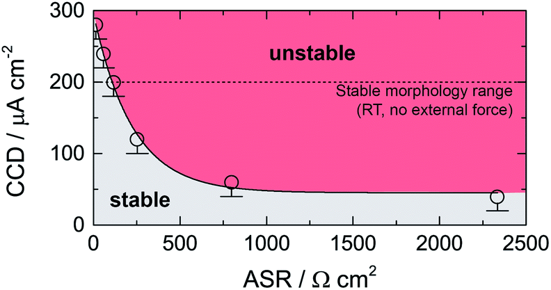 | ||
| Fig. 3 Critical current density (CCD) as a function of the area specific resistance (ASR). Solid line represents an exponential function. The dashed line indicates the theoretical limit as suggested by theoretical considerations using a relaxation model.31 See text for further explanation. | ||
We have to note that comparing CCD values with those from earlier reports is only possible to a limited extent as experimental conditions differ from study to study (see Table 2). For example, applying external pressures plastically deforms lithium and increases creep, which decreases the drive of pore formation and, therefore, increases the CCD.10 Hence, pressures of approximately 3 MPa could explain CCD values of approximately 1 mA cm−2 as reported recently.9,24
| Composition | ρ rel/g cm−3 | ASR/Ω cm2 | CCD/μA cm−2 | T/°C | p/MPa | Reference |
|---|---|---|---|---|---|---|
| a Use of an Au interlayer. b LG: large grains, SG: small grains. c Air: sintered in air, O2: sintered in oxygen, mod: 2% LiOH was added before the 2nd calcination step (formation of a glassy interlayer). d More than 40 times higher surface area leads to an ASR value of 280 Ω cm2 and a CCD value of 0.25 mA cm−2. RT denotes room temperature. | ||||||
| LLZO-13 | 100 | 13 | 280 | 20 | — | This study |
| LLZO-56 | 100 | 56 | 240 | 20 | — | This study |
| LLZO-118 | 100 | 116 | 200 | 20 | — | This study |
| LLZO-253 | 100 | 253 | 120 | 20 | — | This study |
| LLZO-797 | 100 | 797 | 60 | 20 | — | This study |
| LLZO-2335 | 100 | 2335 | 40 | 20 | — | This study |
| Li6.25Al0.25La3Zr2O12/Li6.5Al0.15La3Zr1.5Ta0.5O12a | >99 | 9–15 | 900(700) | 25 | 3.3 | Tayler et al.24 |
| Li6.25Al0.25La3Zr2O12/Li6.5Al0.15La3Zr1.5Ta0.5O12a | >99 | 9–15 | 900(700) | 25 | 3.3 | Tayler et al.24 |
| Li6.25Al0.25La3Zr2O12 | 97 ± 1 | 514 | 50 | 30 | 0.35 | Sharafi et al.33 |
| 930(270) | 25 | 3.4 | Wang et al.9 | |||
| Li6.25Al0.25La3Zr2O12 | 96.0–99.4 | 2–5 | 300–600 | ∼RT | 3.5 | Sharafi et al.34 |
| Li6.25Al0.25La3Zr2O12 LGb | 90 | 130 | 46 | ∼RT | 0.2 | Cheng et al.7 |
| Li6.25Al0.25La3Zr2O12 SGb | 92 | 37 | 134 | ∼RT | 0.2 | Cheng et al.7 |
| Li6.5Al0.15La3Zr1.5Ta0.5O12 | — | 520 | 200 | 25 | 1.4 | Basappa et al.35 |
| Li6.5La3Zr1.5Ta0.5O12 | — | 400 | 400 | 25 | 1.4 | Basappa et al.35 |
| Li6.5La3Zr1.5Ta0.5O12-airc | 96.6 | 47–69 | 150 | 25 | 1.4 | Basappa et al.36 |
| Li6.5La3Zr1.5Ta0.5O12-O2c | 95.8 | 47–69 | 400 | ∼RT | 1.4 | Basappa et al.36 |
| Li6.5La3Zr1.5Ta0.5O12-modc | 96.4 | 47–69 | 600 | ∼RT | 1.4 | Basappa et al.36 |
| Li6.55Ga0.15La3Zr2O12 | 95 | 16.7 | 160 | ∼RT | Coin cell | Pesci et al.37 |
| Li6.55Al0.15La3Zr2O12 | 95 | 12.1 | 100 | ∼RT | Coin cell | Pesci et al.37 |
| Li6.6Al0.15La3Zr1.6Ta0.4O12a | 99 | 380 | 500 | 25 | 0.1 | Tsai et al.8 |
| Li6.25Al0.25La3Zr2O12 | 97(1) | ∼200 | 100 | ∼RT | 0.32 | Cheng et al.38 |
| Li6.75La2.75Ca0.25Zr1.5Nb0.5O12d | >99 | 7 | 10000 | ∼RT | Button cell | Hitz et al.39 |
Despite of stack pressure, also temperature and increasing interfacial areas improve the CCD values.9,32 For example, at elevated T Li diffusivity and creep is increased9 leading to an enhancement of the CCD reaching 6.7 mA cm−2 at T = 100 °C. If the interfacial contact area has increased by a factor of 40, extremely high CCD values of 10 mA cm−2 have been reported.39 Considering the effective interface area, a CCD value of 10 mA cm−2 corresponds to an Ieff value of 250 μA cm−2, which is similar to the values obtained herein. It has to be noted that so-called “soft” shorts can lead to overestimated CCD values.40 In contrast to “hard” shorts indicated by an immediate potential drops to zero soft shorts “mimic” a highly stable cycling behavior after a significant potential drop. The behavior is related to the formation of direct electronic pathways between the electrodes through the growth of Li metal.40 Thereafter, high currents will run along these electronic paths generating heat that melts the Li filament by a Joule heating effect. After cooling, the filament is potentially fragmented and, therefore, the short-circuit junction across the ceramic disappears.29 This behavior enables continuous cycling, which, however, strongly deviates from classic ohmic behavior.29 Such a non-ohmic cycling behavior is observed for most cells studied herein. Further evidence for the occurrence of such “soft” shorts can be provided by impedance data recorded after cycling; as an example, the impedance response of sample LLZO-113 after cycling is very similar to that before cycling.40,41
Overall, we believe that experimentally determined CCD values do not represent the intrinsically highest achievable values. Without applying external pressure rough surfaces lead to less good electrolyte|Li metal contacts, which is indirectly seen in increased ASR values. Furthermore, Li metal stripping reduces the interfacial area significantly.10 Such a decrease in contact area causes a huge increase in ASR (ASReff) and on the Ieff (see Fig. S1†). To illustrate this effect on the CCD, increasing the contact area by 20 (40, 60, 80) and 90% changes the Ieff, calculated with regard to the electrode size, from 0.2 mA cm−2 (0.25 mA cm−2, 0.33 mA cm−2, 0.5 mA cm−2, 1.0 mA cm−2) to 2 mA cm−2. This comparison suggests that much higher CCD values would be achievable in the case of perfect Li wetting and ideal layer-by-layer stripping/platting, that is, under the conditions of externally applied pressure and/or at high temperatures. Since cells mainly operate at moderate temperature, stack pressure is needed to achieve the target current density of 3 mA cm−2 in solid-state batteries.
Failure mechanism
In a very recent experimental paper by Li and Monroe, the authors report about the mechanism of dendrite nucleation.42 They showed that the stress associated with dendrite growth is about 1 kPa. This value is far below the fracture stress of about |Δp| = 6 MPa for LLZO.43 Based on this observation they claim that dendrites will not form by a purely mechanical brittle-fracture process as suggested earlier.22 Since we want to understand the impact of the ASR on |Δp| we calculated |Δp| for the cells studied here according to |Δp| = 2πfint(6εbulkCCD)1/2, with εbulk = εrelε and εrel ≈ 50.42,44 In contrast to the earlier report, the values obtained range from 5 × 10³ Pa to 7 × 10⁵ Pa. The significantly higher values correspond to higher ASR values. However, |Δp| is still below the fracture stress of LLZO. Considering the change of the contact area the effective current Ieff applied at a certain area increases tremendously. For instance, a decrease of the contact area by 20% (40%, 60%, 80%, 90%) and 95% causes |Δp| to increase from the initially 1 kPa, with a I of 100 μA cm−2, by approximately 50% (200%, 500%, 2500%, 10![[thin space (1/6-em)]](https://www.rsc.org/images/entities/char_2009.gif) 000%) and finally 380000%. This comparison suggests that the locally restricted pressure will become high enough during cycling to cause mechanical failure. The interrelation of the ASR, CCD, and |Δp|, respectively, as a function of the change in contact area during cycling is illustrated in Fig. S1.†
000%) and finally 380000%. This comparison suggests that the locally restricted pressure will become high enough during cycling to cause mechanical failure. The interrelation of the ASR, CCD, and |Δp|, respectively, as a function of the change in contact area during cycling is illustrated in Fig. S1.†
For the case that |Δp| < 6 MPa, an alternative mechanism, a so-called “grain coating” process, has been proposed.45 This mechanism is based on chemical deposition energetics suggesting that the formation of a new phase is energetically favored in grain boundary regions. Based on the formalism proposed by the authors, they admit the possibility of sporadic bulk platting even in non-adjacent grain boundaries, which is similar to the study by Han et al.46 The mechanism suggested needs electrons to reduce Li from Li+ to Li0. Hence, a relatively high electronic conductivity is required to promote Li metal penetration via a grain boundary mechanism. The bulk electronic conductivity of single-crystalline Ga-stabilized LLZO is, however, in the order of 5 × 10⁻¹⁰ S cm−1. This value is, in our opinion, too low to support this mechanism.47 For polycrystalline phases the presence of extra phases at grain boundaries is, however, very common; thus, we anticipate the presence of electronically conducting phases in or near the grain boundaries regions of such samples. Thus, the mechanism proposed might indeed contribute to the initial filling of flaws (or pores and grain boundaries in polycrystalline samples at the Li|LLZO interface).
Because of the large local current densities caused by pore formation and high initial ASR values, Li+ migration towards the interface is much larger than the flux of Li0 away from the interface.9–11 Hence, Li+ is forced to plate on the Li metal–LLZO contact points. Because of this unbalanced flux and because of the relevant surface energetics,43 Li metal starts to fill the flaws (or any other surface defects in the case of polycrystalline samples). As soon as this Li plating has started, the lower overpotential of the freshly Li deposited combined with an increased electric field in these regions forces Li+ to preferably plate on the tip of this metal filament until the voids are filled completely.22 In addition, hydrostatic compression eventually hardens Li metal in the very next proximity of the Li|LLZO interface. This effect might slow down Li0 diffusivity and consequently leads to an acceleration of Li platting on the tip of the freshly nucleated Li metal.9,13 After the flaws are completely filled, stress accumulates at the tip of the Li metal filament as a function of the current density, which induces crack opening and Li metal penetration, finally resulting in a short circuit.22 Further evidence for a mechanically driven failure mechanism is given by in operando optical microscopy studies showing clearly crack opening before Li metal penetration starts.29
Conclusions
We investigated the interrelation of the area specific resistance and the critical current density in symmetrical Li-metal cells using a Czochralski-grown cubic Li6.4Ga0.2La3Zr2O12 single crystal as a model system for Li7La3Zr2O12 variants. Based on galvanostatic cycling experiments and impedance spectroscopy we observed an exponential dependence of the critical current density on the area specific resistance. Since single crystals have less defects as compared to polycrystals, which are equipped with, e.g., voids and grain boundary regions, the critical current density value of approximately 300 μA cm−2 obtained here represent the upper limit for Li7La3Zr2O12 at room temperature without applying any external forces. Our results suggest that either pressure or a significant increase in the interfacial area is needed to reach current densities being larger than 3 mA cm−2, which are necessary from a practical point of view to realize high power all-solid-state batteries.Conflicts of interest
There are no conflicts to declare.Acknowledgements
DR thanks the Austrian Science Fund (FWF) for financial support (project no. P25702).Notes and references
- PNNL, Energy Storage: Battery500, https://energystorage.pnnl.gov/battery500.asp, accessed 8 November 2019 Search PubMed.
- Electric Vehicle Battery: Materials, Cost, Lifespan, Union of Concerned Scientists, https://www.ucsusa.org/clean-vehicles/electric-vehicles/electric-cars-battery-life-materials-cost, accessed 17 June 2019 Search PubMed.
- ARPA-E|IONICS, https://arpa-e.energy.gov/?q=arpa-e-programs/ionics, accessed 8 November 2019 Search PubMed.
- R. Murugan, V. Thangadurai and W. Weppner, Angew. Chem., Int. Ed., 2007, 46, 7778–7781 CrossRef CAS PubMed.
- V. Thangadurai, S. Narayanan and D. Pinzaru, Chem. Soc. Rev., 2014, 43, 4714 RSC.
- Y. Zhu, X. He and Y. Mo, ACS Appl. Mater. Interfaces, 2015, 7, 23685–23693 CrossRef CAS PubMed.
- L. Cheng, W. Chen, M. Kunz, K. Persson, N. Tamura, G. Chen and M. Doeff, ACS Appl. Mater. Interfaces, 2015, 7, 2073–2081 CrossRef CAS PubMed.
- C.-L. Tsai, V. Roddatis, C. V. Chandran, Q. Ma, S. Uhlenbruck, M. Bram, P. Heitjans and O. Guillon, ACS Appl. Mater. Interfaces, 2016, 8, 10617–10626 CrossRef CAS PubMed.
- M. Wang, J. B. Wolfenstine and J. Sakamoto, Electrochim. Acta, 2019, 296, 842–847 CrossRef CAS.
- T. Krauskopf, H. Hartmann, W. G. Zeier and J. Janek, ACS Appl. Mater. Interfaces, 2019, 11, 14463–14477 CrossRef CAS PubMed.
- J. Kasemchainan, S. Zekoll, D. Spencer Jolly, Z. Ning, G. O. Hartley, J. Marrow and P. G. Bruce, Nat. Mater., 2019, 1–7 Search PubMed.
- A. Masias, N. Felten, R. Garcia-Mendez, J. Wolfenstine and J. Sakamoto, J. Mater. Sci., 2019, 54, 2585–2600 CrossRef CAS.
- W. S. LePage, Y. Chen, E. Kazyak, K.-H. Chen, A. J. Sanchez, A. Poli, E. M. Arruda, M. D. Thouless and N. P. Dasgupta, J. Electrochem. Soc., 2019, 166, A89–A97 CrossRef CAS.
- M. J. Wang, R. Choudhury and J. Sakamoto, Joule, 2019, 2, 2165–2178 CrossRef.
- R. Inada, S. Yasuda, H. Hosokawa, M. Saito, T. Tojo, Y. Sakurai, R. Inada, S. Yasuda, H. Hosokawa, M. Saito, T. Tojo and Y. Sakurai, Batteries, 2018, 4(26), 1–12 Search PubMed.
- L. Cheng, E. J. Crumlin, W. Chen, R. Qiao, H. Hou, S. Franz Lux, V. Zorba, R. Russo, R. Kostecki, Z. Liu, K. Persson, W. Yang, J. Cabana, T. Richardson, G. Chen and M. Doeff, Phys. Chem. Chem. Phys., 2014, 16, 18294–18300 RSC.
- A. Sharafi, S. Yu, M. Naguib, M. Lee, C. Ma, H. M. Meyer, J. Nanda, M. Chi, D. J. Siegel and J. Sakamoto, J. Mater. Chem. A, 2017, 5, 13475–13487 RSC.
- X. Han, Y. Gong, K. Fu, X. He, G. T. Hitz, J. Dai, A. Pearse, B. Liu, H. Wang, G. Rubloff, Y. Mo, V. Thangadurai, E. D. Wachsman and L. Hu, Nat. Mater., 2017, 16, 572–579 CrossRef CAS PubMed.
- W. Luo, Y. Gong, Y. Zhu, K. K. Fu, J. Dai, S. D. Lacey, C. Wang, B. Liu, X. Han, Y. Mo, E. D. Wachsman and L. Hu, J. Am. Chem. Soc., 2016, 138, 12258–12262 CrossRef CAS PubMed.
- C. Wang, Y. Gong, B. Liu, K. Fu, Y. Yao, E. Hitz, Y. Li, J. Dai, S. Xu, W. Luo, E. D. Wachsman and L. Hu, Nano Lett., 2017, 17, 565–571 CrossRef CAS PubMed.
- A. Sharafi, E. Kazyak, A. L. Davis, S. Yu, T. Thompson, D. J. Siegel, N. P. Dasgupta and J. Sakamoto, Chem. Mater., 2017, 29, 7961–7968 CrossRef CAS.
- L. Porz, T. Swamy, B. W. Sheldon, D. Rettenwander, T. Frömling, H. L. Thaman, S. Berendts, R. Uecker, W. C. Carter and Y.-M. Chiang, Adv. Energy Mater., 2017, 7, 1701003 CrossRef.
- T. Swamy, R. Park, B. W. Sheldon, D. Rettenwander, L. Porz, S. Berendts, R. Uecker, W. C. Carter and Y.-M. Chiang, J. Electrochem. Soc., 2018, 165, A3648–A3655 CrossRef CAS.
- N. J. Taylor, S. Stangeland-Molo, C. G. Haslam, A. Sharafi, T. Thompson, M. Wang, R. Garcia-Mendez and J. Sakamoto, J. Power Sources, 2018, 396, 314–318 CrossRef CAS.
- D. Rettenwander and H. M. R. Wilkening, in preparation.
- J. T. S. Irvine, D. C. Sinclair and A. R. West, Adv. Mater., 1990, 2, 132–138 CrossRef CAS.
- D. Rettenwander, A. Welzl, L. Cheng, J. Fleig, M. Musso, E. Suard, M. M. Doeff, G. J. Redhammer and G. Amthauer, Inorg. Chem., 2015, 54, 10440–10449 CrossRef CAS PubMed.
- J. Fleig and J. Maier, J. Am. Ceram. Soc., 2004, 82, 3485–3493 CrossRef.
- W. Manalastas, J. Rikarte, R. J. Chater, R. Brugge, A. Aguadero, L. Buannic, A. Llordés, F. Aguesse and J. Kilner, J. Power Sources, 2019, 412, 287–293 CrossRef CAS.
- O. Knacke and I. N. Stranski, in Ergebnisse der Exakten Naturwissenschaften, Springer Berlin Heidelberg, 2007, pp. 383–427 Search PubMed.
- H. Schmalzried and J. Janek, Berichte der Bunsengesellschaft für physikalische Chemie, 1998, 102, 127–143 CrossRef CAS.
- W. Luo, Y. Gong, Y. Zhu, Y. Li, Y. Yao, Y. Zhang, K. K. Fu, G. Pastel, C. F. Lin, Y. Mo, E. D. Wachsman and L. Hu, Adv. Mater., 2018, 29, 1606042 CrossRef PubMed.
- A. Sharafi, H. M. Meyer, J. Nanda, J. Wolfenstine and J. Sakamoto, J. Power Sources, 2016, 302, 135–139 CrossRef CAS.
- A. Sharafi, C. G. Haslam, R. D. Kerns, J. Wolfenstine and J. Sakamoto, J. Mater. Chem. A, 2017, 5, 21491–21504 RSC.
- R. H. Basappa, T. Ito and H. Yamada, J. Electrochem. Soc., 2017, 164, A666–A671 CrossRef CAS.
- R. Hongahally Basappa, T. Ito, T. Morimura, R. Bekarevich, K. Mitsuishi and H. Yamada, J. Power Sources, 2017, 363, 145–152 CrossRef CAS.
- F. M. Pesci, R. H. Brugge, A. K. O. O. Hekselman, A. Cavallaro, R. J. Chater and A. Aguadero, J. Mater. Chem. A, 2018, 6, 19817–19827 RSC.
- E. J. Cheng, A. Sharafi and J. Sakamoto, Electrochim. Acta, 2017, 223, 85–91 CrossRef CAS.
- G. T. Hitz, D. W. McOwen, L. Zhang, Z. Ma, Z. Fu, Y. Wen, Y. Gong, J. Dai, T. R. Hamann, L. Hu and E. D. Wachsman, Mater. Today, 2019, 22, 50–57 CrossRef CAS.
- P. Albertus, S. Babinec, S. Litzelman and A. Newman, Nat. Energy, 2018, 3, 16–21 CrossRef CAS.
- R. Hernandez-Maya, O. Rosas, J. Saunders and H. Castanedaa, J. Electrochem. Soc., 2015, 162, A687–A696 CrossRef CAS.
- G. Li and C. W. Monroe, Phys. Chem. Chem. Phys., 2019, 21, 20354–20359 RSC.
- A. Foster, Master thesis, Michigan State University, USA, 2016.
- D. Rettenwander, A. Welzl, L. Cheng, J. Fleig, M. Musso, E. Suard, M. M. Doeff, G. J. Redhammer and G. Amthauer, Inorg. Chem., 2015, 54, 10440–10449 CrossRef CAS PubMed.
- C. Monroe and J. Newman, J. Electrochem. Soc., 2004, 151, A880–A886 CrossRef CAS.
- F. Han, A. S. Westover, J. Yue, X. Fan, F. Wang, M. Chi, D. N. Leonard, N. J. Dudney, H. Wang and C. Wang, Nat. Energy, 2015, 54, 10440–10449 Search PubMed.
- M. Philipp, D. Rettenwander and H. M. R. Wilkening, to be published.
Footnote |
| † Electronic supplementary information (ESI) available. See DOI: 10.1039/c9ta14177d |
| This journal is © The Royal Society of Chemistry 2020 |