 Open Access Article
Bifunctional polymer-of-intrinsic-microporosity membrane for flexible Li/Na–H2O2 batteries with hybrid electrolytes†
Yunfeng
Zhao
 a,
Xiaorong
Ma
a,
Pengli
Li
a,
Yang
Lv
a,
Xiaorong
Ma
a,
Pengli
Li
a,
Yang
Lv
 a,
Jianfeng
Huang
b,
Haixia
Zhang
a,
Yongli
Shen
a,
Qibo
Deng
a,
Jianfeng
Huang
b,
Haixia
Zhang
a,
Yongli
Shen
a,
Qibo
Deng
 a,
Xizheng
Liu
 *a,
Yi
Ding
a and
Yu
Han
 *c
*c
aTianjin Key Laboratory of Advanced Functional Porous Materials, Institute for New Energy Materials & Low-Carbon Technologies, School of Materials Science and Engineering, Tianjin University of Technology, Tianjin 300384, China. E-mail: xzliu@tjut.edu.cn
bMulti-scale Porous Materials Center, Institute of Advanced Interdisciplinary Studies, School of Chemistry and Chemical Engineering, Chongqing University, Chongqing 400044, P. R. China
cAdvanced Membranes and Porous Materials Center, King Abdullah University of Science and Technology, Thuwal 23955-6900, Kingdom of Saudi Arabia. E-mail: yu.han@kaust.edu.sa
First published on 29th January 2020
Abstract
Polymeric membranes with high ionic conductivity and solvent molecule blocking capability are attracting considerable attention as separators for new-generation batteries adopting hybrid electrolytes. The performances of the membranes are closely dependent on their microstructures and functional groups. Here, we report the design and fabrication of a carboxyl-functionalized polymer-of-intrinsic-microporosity (PIM) membrane, which has optimal surface properties and microporous channels (∼0.8 nm) to permit cation (Li+ or Na+) transportation, while preventing solvent molecule penetration. Using a droplet-templating strategy, we create large pores on both surfaces of the PIM-membrane to improve its interfacial contact with electrolytes. The obtained membrane integrates good mechanical strength with high thermal and electrochemical stability, demonstrating a great potential for battery applications as a flexible separator. When intercalated with Li+, the membrane (PIM-1-COOLi) exhibits a remarkable Li+ conductivity in both aqueous (6.5 × 10⁻³ S cm−1) and organic (7.3 × 10⁻⁴ S cm−1) solutions, as well as a good solvent permeation resistance (19 μmol cm−2 min−1 at 10 Pa for H2O). Taking these advantages of the PIM-membrane, we are able to fabricate challenging batteries with hybrid electrolytes, such as Li–H2O2 and Na–H2O2 batteries (Li/Na anode with organic electrolyte and H2O2 cathode with aqueous electrolyte), into a flexible laminated form. The as-fabricated battery shows an excellent discharge performance, comparable to a model battery constructed with the commercial ceramic Li super-ionic conductor, but is more tolerant to mechanical treatment and harsh environment. Our study demonstrates that PIM represents a promising platform for developing flexible secondary batteries with hybrid electrolytes, which are particularly desirable for wearable and portable electronic devices.
1. Introduction
Ion-conductive membranes have attracted considerable interest in both academia and industry, due to their crucial role in constructing various energy-storage and conversion devices, including metal–air batteries,1 Li–S batteries,2 redox flow batteries,3 and fuel cells.4 In batteries, these membranes act as separators to prevent short-circuit between the cathode and anode, while at the same time conducting guest ions such as Li+, Na+, etc.5 In addition to these two basic functions, a membrane with the ability to block the transport of solvent molecules could allow the cathode and the anode to work in oxidation-resistant and reductive electrolytes, respectively and simultaneously, leading to significant performance improvement and offering opportunities to construct new types of energy devices. The concept of solvent molecule-blocking was first demonstrated by Visco et al. using a nonporous ceramic membrane denoted as “lithium super-ionic conductor (LISICON)”.6 Solvent molecules cannot pass through LISICON, whereas Li-ions are transported by hopping among interstitial sites or vacancies of its crystal lattice.7 On the basis of this concept, organic/aqueous hybrid electrolytes have been used to integrate a high-energy-density anode and an ion-conductive liquid cathode into a single battery.8 Successful examples include Li–air,9 Li-metal/metal oxide,10 Li–NiOOH,11 and Li-redox flow batteries.12 This conceptual advancement not only provides new solutions to fabricate high-energy storage devices, but also expands the battery reaction chemistry.13,14 However, there are some issues associated with ceramic membranes that impede their wide applications: they are rigid and prone to degradation in strongly alkaline or acidic electrolytes,15 their production cost is high, and their ionic conductivities are limited by the efficiency of ion hopping through crystal lattice and usually of relatively low values (10−4 to 10−6 S cm−1 for LISICON).16In comparison with ceramic membranes, polymeric membranes have advantages including lower production cost, higher stability, and better processability. Most importantly, polymeric membranes are flexible, which is crucially important for foldable and wearable devices. Unfortunately, despite the high ionic conductivities, commonly used polymeric ion-conductive membranes, e.g., Nafion, are unable to block solvent molecules,17 and thus unsuitable for new-concept batteries with hybrid electrolytes. Therefore, there is an urgent need to develop a new type of polymeric membrane that combines a high ionic conductivity with an ability to block the shuttling of water and other solvent molecules, while preserving the intrinsic excellent properties of polymers (flexibility, stability, and processability).
Polymers of intrinsic microporosity (PIMs) are a class of polymer that is constructed from stiff monomers (e.g. spiro- or binaphthyl compounds) and featured by rigid, contorted skeleton, large free volume, and uniform ultra-micropores.18,19 Due to these unique properties, PIMs have primarily been used to fabricate highly permeable and selective membranes for gas separation.20,21 Several recent studies reported the use of PIM-based separator membranes for rechargeable batteries: a pristine PIM-1 membrane was used to block shuttling of polysulfur ions in Li–S battery;22 Tröger's base23 and N-spirocyclic quaternary ammonium24 polymer membranes showed the ability to conduct hydroxide (OH−) or proton (H+); an amidoxime-functionalized PIM membrane was used to construct solvent crossover-free Zn-based redox flow batteries.25 It is worth noting that these works mainly focused on the ionic conductivity of the membranes, whereas how to incorporate the “solvent molecule blocking” ability in a polymeric membrane has not been explored and remains a challenge, which requires rational design at the molecule level to achieve precise control of microstructure and functionality of the membrane.
Herein, we report the first polymeric membrane that fulfils the dual function of “cation conduction” and “solvent molecule blocking” for batteries adopting the hybrid electrolytes configuration. This polymer is prepared by modifying a well-established PIM polymer (PIM-1) with carboxyl groups. The modification not only introduces cation conductivity into PIM-1, but also reduces the effective pore size down to an optimal value (∼0.8 nm) to exclude solvent molecules passing through. The membrane fabricated from carboxyl-modified PIM-1 exhibits excellent solvent molecule blocking capability, high ionic conductivity, and good stability. We develop a droplet-templating method to produce large pores on both sides of the membrane, which increase the contact area of the membrane with electrolytes to facilitate ion transportation. As a proof-of-concept, we use this membrane to construct Li/Na–H2O2 batteries, in which reactive alkali metals (Li or Na) serve as anodes in an organic electrolyte and the strong oxidizer (H2O2) in an aqueous electrolyte acts as the active material on the cathode. Any permeation of H2O or H2O2 from the cathode side to anode side would lead to the Li metal corrosion and battery failure. The ability to block solvent molecules and high ionic conductivity of the PIM-1 membranes guarantee the operation of flexible batteries with organic/aqueous hybrid electrolytes.
2. Experimental
2.1 Fabrication of PIM-1-based membranes
PIM-1 synthesis was conducted according to the literature.18 3,3,3′,3′-Tetramethyl-1,1′-spirobiindane-5,5′,6,6′-tetraol (TTSBI, 5.106 g, 5 mmol) and 1,4-dicyanotetrafluorobenzene (DCTB, 3.003 g, 15 mmol) were dissolved in dimethylacetamide (DMAc, 25 mL) under vigorous stirring with N2 protection. Then, potassium carbonate (K2CO3, 6.20 g, 45 mmol) was added and the temperature was maintained at 60 °C for 10 min. The viscosity rapidly increased and precipitation occurred (150 °C for 2 min). Then, two separate portions of 50 mL toluene were added. The synthesized polymer solution was poured into methanol to form a PIM-1 precipitate. The PIM-1 was further purified by boiling in hot water and through reprecipitation in tetrahydrofuran (THF) solution to remove excess K2CO3. The refined PIM-1 powder THF was dried in a vacuum oven at 60 °C for 24 h for further application. Membranes were prepared by casting from chloroform (CHCl3) solution. The polymer solution was prepared by dissolving PIM-1 powder (300 mg) and bistrifluoromethanesulfonimide lithium salt (LiTFSI, 300 mg) in CHCl3 (4 mL). The solution was cast on quartz dishes. A PIM-1 and Li salt hybrid membrane was obtained after drying at room temperature. The PIM-1 hybrid membrane was soaked in a 10 wt% sodium hydroxide (NaOH) solution (H2O/ethanol = 3![[thin space (1/6-em)]](https://www.rsc.org/images/entities/char_2009.gif) :
:![[thin space (1/6-em)]](https://www.rsc.org/images/entities/char_2009.gif) 7). After hydrolysis at 60 °C for 6 h, a PIM-1-COONa membrane was obtained after washing with DI water. A PIM-1-COOLi membrane was obtained through a further ionic exchange in a lithium hydroxide (LiOH) solution (10 wt%).
7). After hydrolysis at 60 °C for 6 h, a PIM-1-COONa membrane was obtained after washing with DI water. A PIM-1-COOLi membrane was obtained through a further ionic exchange in a lithium hydroxide (LiOH) solution (10 wt%).
2.2 Theoretical calculation
The membrane structure was constructed using three polymer chains placed in a 22 × 22 × 22 box using the Amorphous Cell Module of Materials Studio. The density of polymer film is set to be 1.09 g cm−3. With the aim of clarifying the ion transport channel of our membrane, a short molecular dynamics simulation (200 ps) was performed using the NPT ensemble with the COMPASS-II force field, for a time step of 1.0 fs and a finite temperature of 298.15 K.26 The Ewald summation method was used to calculate the long-range van der Waals and Coulomb interactions. The Ewald accuracy was set to 1.0 × 10⁻⁴. Nosé method 1 was used to control the temperature at 298.15 K. All molecular dynamics calculations were conducted using the Forcite package. Domain analysis was performed for this structure using Multiwfn3![[thin space (1/6-em)]](https://www.rsc.org/images/entities/char_2009.gif) 27 and based on the promolecular electron density (ED). The poor domain was defined as a region having ED less than 0.0001 a.u. For this ED threshold, our calculation results revealed the existence of 13 domains. The volume of this channel was estimated to be Å3.
27 and based on the promolecular electron density (ED). The poor domain was defined as a region having ED less than 0.0001 a.u. For this ED threshold, our calculation results revealed the existence of 13 domains. The volume of this channel was estimated to be Å3.
2.3 Pervaporation permeation behaviour of the membrane
The water permeation of the PIM-1-COOLi membrane was analysed using a homemade pervaporation cell. The membrane housing plate provided an effective area of 12.65 cm2 for pervaporation and a 6 cm diameter. The membrane was kept on the downstream side of the cell and was evacuated to a certain vacuum pressure using a vacuum pump. The permeation flux J was calculated from the following equation:28| J = ΔG/A × t, |
2.4 Battery assembly and electrochemical performance
The ionic conductivities of the PIM-1-COOLi/Na membranes were measured from the alternating-current (AC) impedance on an electrochemical workstation (CHI-760, Shanghai) in CR 2032 coin-type cells. The frequency was 100 kHz to 0.01 Hz with an AC potential of 5 mV. The conductivity was calculated from the equation σ = L/RbA where σ is the ionic conductivity (S cm−1) and L and A are the thickness (cm) and area of the separator (cm2), respectively.29 The Li/Na–H2O2 battery structure had the following components: (1) an organic electrolyte of 1 M lithium perchlorate (LiClO4) in ethylene carbonate (EC)/dimethyl carbonate (DEC) (4 mL) and an Li metal anode with a Cu mesh current collector; (2) a catholyte of 5 wt% H2O2 with 0.1 M sodium sulfate (Na2SO4) in an aqueous solution (4 mL); (3) carbon black with Co3O4 as a cathode catalyst; and (4) PIM-1-COOLi/Na membranes or solid-state Li super ionic conductor (LISICON) film as a separator. In the flexible laminated cell, the amount of electrolytes is 1000 μL for both electrodes. Ceramic LISICON film with 150 μm thickness was purchased from Ohara, Japan. The cathode catalyst was prepared according to our previous report.30 The carbon paper was used as a current collector. For the laminated cells, carbon cloth was used as a cathode current collector. The discharge performance was determined using an Arbin battery test system (BT2043).3. Results and discussion
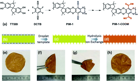
Due to their excellent processability and tunable microporous structures, PIM-1-derived membranes have been intensively and extensively investigated for gas separation.20,21 In this study, we hypothesize that the microporosity of pristine PIM-1 combined with desired cation-conducting groups, which could be generated by post-synthesis modification, would facilitate the conduction of ions through the membrane. To verify this hypothesis, we first synthesized PIM-1 following the well-established protocol (Fig. 1a, see the Experimental section for detail). The as-synthesized PIM-1 has a molecular weight of ∼89![[thin space (1/6-em)]](https://www.rsc.org/images/entities/char_2009.gif) 000 (polydispersity index = 1.65) according to gel permeation chromatography. The high degree of polymerization allows the easy fabrication of mechanically strong membranes. Specifically, 300 mg of PIM-1 polymer was dissolved in 4 mL of CHCl3, and then the solution was casted in a quartz dish with the diameter of 60 mm. After drying at room temperature, the PIM-1 membrane was obtained. The as-prepared pristine PIM-1 membrane is bright-yellow in colour, and possesses an ultra-flat surface and a dense cross-section with a thickness of ∼40 μm (Fig. S1†). We use this pristine PIM-1 membrane as a “reference” material in this study.
000 (polydispersity index = 1.65) according to gel permeation chromatography. The high degree of polymerization allows the easy fabrication of mechanically strong membranes. Specifically, 300 mg of PIM-1 polymer was dissolved in 4 mL of CHCl3, and then the solution was casted in a quartz dish with the diameter of 60 mm. After drying at room temperature, the PIM-1 membrane was obtained. The as-prepared pristine PIM-1 membrane is bright-yellow in colour, and possesses an ultra-flat surface and a dense cross-section with a thickness of ∼40 μm (Fig. S1†). We use this pristine PIM-1 membrane as a “reference” material in this study.
Our designed membrane was fabricated in a similar way as the pristine PIM-1 membrane, except two extra steps: (1) LiTFSI was used as an additive to mix with PIM-1 polymer in the CHCl3 solution before membrane casting; (2) the formed membrane was immersed in a 10 wt% NaOH solution to undergo a hydrolysis process. The aim of the first step is to generate macropores on the surfaces of the membrane by a droplet-templating strategy, in order to enhance its interfacial contact with the electrolytes and thus promote ion transportation (Fig. 1b–d). The polymer to Li salt ratio was optimized according to the mechanical strength, and an optimal ratio of 1![[thin space (1/6-em)]](https://www.rsc.org/images/entities/char_2009.gif) :
:![[thin space (1/6-em)]](https://www.rsc.org/images/entities/char_2009.gif) 1 (PIM
1 (PIM![[thin space (1/6-em)]](https://www.rsc.org/images/entities/char_2009.gif) :
:![[thin space (1/6-em)]](https://www.rsc.org/images/entities/char_2009.gif) LiTFSI) in weight was determined (Fig. S2†). Note that our droplet-templating strategy is based on the reported “breath figure” mechanism,31 where water droplets (in this work, the water droplets are produced by Li salts through adsorbing the vapour from the air) serve as templates for creating pores on the surface of an evaporating polymer solution. The aim of the second step is to convert a portion of the cyano (–CN) groups in PIM-1 into carboxyl (–COOH) groups (Fig. 1a), which can be visualized by the gradually darkened colour of the membrane during the hydrolysis process (Fig. S3†). The hydrolysis conditions have been optimized to achieve a combination of high ionic conductivity with good mechanical strength. The hydrolysis of –CN into –COOH was optimized to yield an ideal membrane with excellent ionic conductivity and mechanical strength, and the weakening of stretching vibration of the –CN group (at ∼2235 cm−1) in Fourier transform infrared spectroscopy (FTIR, Fig. S4†) was employed as an indicator. As evidenced by the FTIR, the hydrolysis was trivial at room temperature (25 °C). Despite that higher temperatures could accelerate the hydrolysis (Fig. S4†), the membrane hydrolysed at 80 °C or above cracks easily. The optimized membrane was achieved by the hydrolysis in 10% NaOH solution (H2O/ethanol = 3
LiTFSI) in weight was determined (Fig. S2†). Note that our droplet-templating strategy is based on the reported “breath figure” mechanism,31 where water droplets (in this work, the water droplets are produced by Li salts through adsorbing the vapour from the air) serve as templates for creating pores on the surface of an evaporating polymer solution. The aim of the second step is to convert a portion of the cyano (–CN) groups in PIM-1 into carboxyl (–COOH) groups (Fig. 1a), which can be visualized by the gradually darkened colour of the membrane during the hydrolysis process (Fig. S3†). The hydrolysis conditions have been optimized to achieve a combination of high ionic conductivity with good mechanical strength. The hydrolysis of –CN into –COOH was optimized to yield an ideal membrane with excellent ionic conductivity and mechanical strength, and the weakening of stretching vibration of the –CN group (at ∼2235 cm−1) in Fourier transform infrared spectroscopy (FTIR, Fig. S4†) was employed as an indicator. As evidenced by the FTIR, the hydrolysis was trivial at room temperature (25 °C). Despite that higher temperatures could accelerate the hydrolysis (Fig. S4†), the membrane hydrolysed at 80 °C or above cracks easily. The optimized membrane was achieved by the hydrolysis in 10% NaOH solution (H2O/ethanol = 3![[thin space (1/6-em)]](https://www.rsc.org/images/entities/char_2009.gif) :
:![[thin space (1/6-em)]](https://www.rsc.org/images/entities/char_2009.gif) 7) at 60 °C for 6 h. The corresponding hydrolysis percentage of the –CN group is approximately 50%, as determined by the elemental analysis.32 A higher degree of hydrolysis would lead to a fragile membrane.
7) at 60 °C for 6 h. The corresponding hydrolysis percentage of the –CN group is approximately 50%, as determined by the elemental analysis.32 A higher degree of hydrolysis would lead to a fragile membrane.
After the hydrolysis process, we further converted the membrane to its Li-form or Na-form by an ion-exchange process (see the Experimental section) for further characterization and battery applications. The resulting membrane (denoted as PIM-1-COOLi or PIM-1-COONa) exhibited excellent flexibility, and retained good integrity even after repeated folding and unfolding (Fig. 1e–h). Unlike the pristine PIM-1 membrane that has flat surfaces, PIM-1-COOLi has both sides of the surface full of highly open macropores (∼1.7 μm in diameter) with a high density, as revealed by scanning electron microscopy (SEM) (Fig. 2a and b). The cross-section of PIM-1-COOLi has a sandwich structure, consisting of two macroporous skin layers of thickness ∼10 μm and a dense internal layer with a thickness of ∼23 μm (Fig. 2c). The macropores observed at the cross-section are 10–30 μm in diameter (highlighted by red circles in Fig. 2c), which are interconnected with smaller channels, as indicated by arrows in Fig. 2c. The SEM characterization confirms the successful fabrication of the designed membrane morphology. In addition to the macroscopic membrane morphology, PIM-1-COOLi also differs from the pristine PIM-1 membrane in microporosity. As determined from the CO2 adsorption isotherms collected at 273 K, PIM-1-COOLi has a markedly smaller micropore size compared to pristine PIM-1 membrane (0.8 nm vs. 1.3 nm) (Fig. S5 & S6†). The narrowing of micropores is the consequence of the generation of carboxyl groups, and it is expected to favour the blocking of solvent molecules.
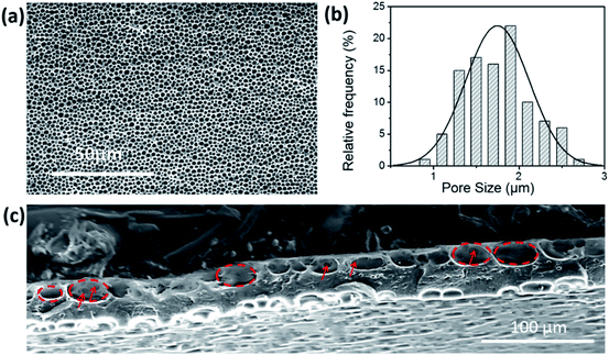 | ||
| Fig. 2 (a) SEM image (b) and the corresponding statistical pore-size analysis of the surface of the PIM-1-COOLi membrane. (c) SEM image of the cross-section of the PIM-1-COOLi membrane. | ||
We use the Polymatic simulated polymerization algorithm33 to model the ionic transportation channel of PIM-1-COOLi, based on polymer chains containing 15 repeating units (Fig. 3a). The results show that the stereoscopic-structure Spiro centre causes a loose packing of the polymer chains, generating intrinsic microporosity (Fig. 3b). Through van der Waals surface analysis of the micropores, we found that the carboxyl groups are mainly distributed inside the pore channel, leaving sufficient space and ion-bonding sites to ensure the guest-ion conduction (Fig. 3c). To study the solvent-permeation resistance of the PIM-1-COOLi membrane, we measured the permeation rate of water under different pressures using a home-made apparatus (Fig. S7†). The results showed that water molecules could not pass through the membrane under ambient-pressure; under near-vacuum conditions (10 Pa), the permeability was measured to be 19 μmol cm−2 min−1, according to the pervaporation data (Fig. S8†), which is almost 50-fold smaller than the value measured for the Nafion 117 membrane (930 μmol cm−2 min−1).34 Due to the limited availability of the organic solvent used in our battery (i.e., EC/DEC), we did not measure its permeability on the PIM-1-COOLi membrane directly. However, it is conceivable that the membrane is much less permeable for ethylene carbonate/diethyl carbonate than for water, as we found the permeability on PIM-1-COOLi decreases as the molecular size increases (e.g., 0.38 μmol cm−2 min−1 for methanol and 0.15 μmol cm−2 min−1 for ethanol) (Fig. S8†), which confirms a size-exclusion effect.
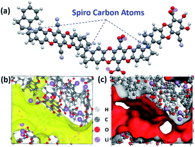 | ||
| Fig. 3 (a) Structural model of a segment of the PIM-1-COOLi chain. (b and c) channel structure (b) and van der Waals surface (ED = 0.001 a.u.) (c) of PIM-1-COOLi. | ||
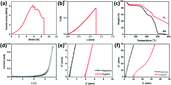
Because metallic Li anode often forms Li dendrites during battery cycling that can propagate through separators to cause an internal short-circuit between the two electrodes, the separator membranes need mechanical strength to resist the punch of Li dendrites. The mechanical strength of the PIM-1-COOLi membrane was characterized by stretching and punching in a mechanical testing machine (Fig. S9†). To perform the tensile strength test, the membranes were cut into rectangular pieces (5.0 mm × 25.0 mm) and then were applied with a tensile force at a quasi-static speed of 1 mm min−1 at room temperature. As shown in Fig. 4a, the utmost tensile stress the PIM-1-COOLi membrane (thickness: 40 μm) could tolerate before failure was 6 MPa, under which the strain reached 7.8%. Moreover, the fracture curve shows that the stress decreased slowly with the increase of the strain, which suggests that PIM-1-COOLi has certain ductility, consistent with its good flexibility demonstrated in Fig. 1. The result of a puncture test shows that the PIM-1-COOLi membranes could withstand a high punching force of up to 0.15 N at a large elastic deformation of 1.2 mm (Fig. 4b). We also evaluated the thermal stability of the PIM-1-COOLi membrane based on a thermal degradation analysis within the temperature range of 30–800 °C in both N2 and air atmosphere. The results show that the membrane remained undecomposed at up to 320 °C, a temperature much higher than the conventional operating temperature of batteries (Fig. 4c). In addition, linear scanning cyclic voltammetry revealed an unaltered electrochemical behaviour of the PIM-1-COOLi membrane at <4.0 V, indicating its promise as a separator for rechargeable batteries (Fig. 4d).
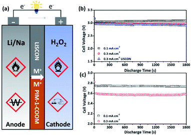
To measure the ionic conductivity, the PIM-1-COOLi membrane was assembled into coin-type cells containing an either aqueous (i.e., 0.1 M LiOH in H2O) or organic (i.e., 0.1 M LiClO4 in EC/DEC) electrolyte in each test (Fig. S10†). Fig. 4e presents the Nyquist plots of the PIM-1-COOLi membrane at room temperature, from which the Li+ conductivity was calculated to be 6.5 × 10⁻³ S cm−1 in the aqueous electrolyte or 7.3 × 10⁻⁴ S cm−1 in the organic electrolyte. The PIM-1-COONa membrane was examined in the same way except that 0.1 M NaOH aqueous solution was used. The determined Na+ conductivity of the PIM-COONa membrane is 2.2 × 10⁻³ and 8.7 × 10⁻⁵ S cm−1 in the aqueous and organic solution, respectively (Fig. 4f). In comparison with various reported ion-conductive membranes, PIM-1-COOLi/Na membranes are among the state-of-the-art membranes in terms of ion conductivity (Table S1†).35–38 By contrast, the pristine PIM-1 does not show detectable ion conductivity, due to the absence of ionic conducting groups, and inadequately-hydrolysed PIM membranes display intermediate ion conductivities (see Fig. S11 and S12†). These results confirm a strong correlation between the carboxyl group and the ion transportation. It is interesting to note that the PIM-1-COOLi membrane exhibited good wetting with both EC/DEC solvent (contact angle: 90°) and water (contact angle: 99°) (Fig. S13†). This amphiphilicity is likely due to the coexistence of –CN and –COOH groups which are of hydrophilic and lipophilic property, respectively, as well as the designed macroporous membrane surface structure. Such amphiphilic behaviour certainly promotes the interfacial infiltration of electrolytes to reduce the charge-transfer resistance. On the basis of these excellent properties, we assembled Li/Na–H2O2 batteries using organic/aqueous hybrid electrolytes and PIM-1-COOLi/Na as separator membranes (Fig. S14†). In these batteries, the very reactive alkali metal (i.e., Li or Na) in the organic electrolyte (i.e., EC/DEC) and the strong oxidizer H2O2 in the aqueous electrolyte serves as the anode and the cathode, respectively (Fig. 5a). The battery reactions are as follows:
| Cathode: H2O2 + 2e → 2OH− |
| Anode: Li (Na) → Li (Na)+ + e |
| Overall reaction: Li (Na) + H2O2 → Li (Na)OH |
The results of galvanostatic discharge testing showed that the Li–H2O2 battery delivered a constant output voltage of 3.2 V at a current density of 0.1 mA cm−2 during discharge, while it only slightly decreased to 3.0 V, as the current density increased to 0.3 mA cm−2 (Fig. 5b). For comparison purpose, another battery was assembled in exactly the same configuration except that a LISICON membrane was used as the separator. The comparison results indicate that in terms of the discharge voltage, PIM-1-COOLi is even slightly superior to LISICON at high current densities (i.e., 0.3 mA cm−2) (Fig. 5b). It is worth noting that although LISICON has combined properties of Li+ transport and solvent blocking, its instability in strong bases or acids and the poor mechanical flexibility hinder practical applications. When a LISICON film is bent or crushed, the resultant cracks reduce the resistance against H2O permeation and consequently incur safety problems. In contrast, the PIMs maintain robust flexibility even after extreme folding (Fig. 1h) and more stable under harsh conditions (e.g., the hydrolysis process in 10 wt% NaOH under 60 °C for 6 h). The galvanostatic discharge testing was also performed for a Na–H2O2 battery that was assembled using the PIM-1-COONa membrane, which yielded a high discharge voltage of 2.75 and 2.50 V at a current density of 0.1 and 0.3 mA cm−2, respectively (Fig. 5c).
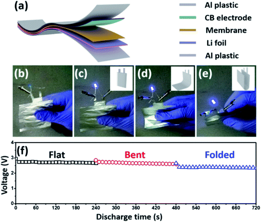
Finally, we integrated the PIM-1-based membrane into a flexible Li–H2O2 battery with organic/aqueous hybrid electrolytes, and evaluated the battery performance in different bending states. As illustrated in Fig. 6a, the flexible battery is fabricated in a laminated manner, in which a carbon black (CB)-coated Ti foil and a metallic Li foil served as the cathode and anode, respectively. The PIM-1-COOLi membrane separated the cathodic and anodic compartment, which was filled with an aqueous H2O2 solution and an organic EC/DEC solvent, respectively. A piece of aluminium-plastic film was used as the cover on each side of the battery, and the battery was assembled on a thermocompressor. As evidenced by the consistent illumination of a commercial blue-light-emitting diode powered by the flexible battery under different bending conditions (Fig. 6b–e and ESI Video†), the battery is able to deliver a stable discharge voltage regardless of its bending degree (Fig. 6f). Also, the fabricated cathode displays robust stability during the cycling process in Li–H2O2 cell as the morphology of composite electrode are barely changed after discharging (Fig. S15†). Although the voltage (∼3 V) is slightly lower than that of the model cell due to the different battery configurations, the results here unambiguously demonstrate the good performance of this PIM-incorporated Li–H2O2 cell, and further confirm that the membrane possesses excellent ionic conductivity and solvent penetration resistance, high flexibility, and stable mechanical/electrochemical properties. These characteristics are favourable for not only flexible Li/Na–H2O2 batteries, but also other advanced batteries featuring hybrid electrolytes.
4. Conclusions
In summary, the intrinsic microporosity and tunable functionality of PIMs provide new opportunities for the design of flexible ion-conducting solvent-blocking membranes for new-concept hybrid-electrolyte batteries. In our designed PIM-1-COOLi/Na membranes, the non-closed packing of the carboxyl functionalized stereo-chains provides 0.8 nm-sized channels that are ideal for selective ion transportation and solvent molecule blocking. The membranes deliver excellent Li+ or Na+ conductivity in both water and organic electrolytes, surpassing most ionic conductors reported to date, and they also possess superior thermal and mechanical stability. In the model Li/Na–H2O2 batteries, a discharge plateau of 3.0 V (for Li anode)/2.5 V (for Na anode) at a current density of 0.3 mA cm−2 was obtained without obvious voltage decay during long-term discharge. Such a battery performance achieved by our flexible polymeric membrane is comparable (even slightly superior) to that obtained on a similar battery using a commercial inorganic membrane, LISICON. Moreover, the true value of our membrane has been further demonstrated by using it to fabricate a laminated hybrid Li–H2O2 cell that exhibits stable performance and robust flexibility. We therefore conclude that membranes made of polymers with intrinsic microporosity have great potential to be used as separators for flexible devices with hybrid electrolytes, such as alkali metal-ion, metal–air, and flow batteries.5. Authors contributions
Y. H., Y. Z., and X. L. conceived and designed the experiments. X. M., P. L., and Y. L. synthesized the polymer and fabricated the membranes. H. Z., Y. S., and Q. D. measured the ion-conductivity data, and evaluated the battery performances. Y. H., Y. Z., X. L., J. H., and Y. D. wrote the manuscript and all authors commented on the manuscript.Conflicts of interest
There are no conflicts to declare.Acknowledgements
This work was supported by the National Key Research and Development Program of China (2019YFA0705700), the National Natural Science Foundation of China (21506148, 21603162, 5171101212), the National Science Fund for Distinguished Young Scholars (51825102), and the Natural Science Foundation of Tianjin City (16ZXCLGX00120). Y. S. acknowledges the National Supercomputing Center in Shenzhen for providing the computational resources and materials studio (V. 7.0, DMol3).Notes and references
- H. Yadegari and X. Sun, Acc. Chem. Res., 2018, 51, 1532–1540 CrossRef CAS PubMed.
- Y. Liu, P. He and H. Zhou, Adv. Energy Mater., 2018, 8, 1701602 CrossRef.
- R. Yon and Q. Wang, Adv. Mater., 2018, 30, 1802406 CrossRef.
- G. L. Wang, L. L. Zou, Q. H. Huang, Z. Q. Zou and H. Yang, J. Mater. Chem. A, 2019, 7, 9447–9477 RSC.
- W. Lu, Z. Yuan, Y. Zhao, H. Zhang, H. Zhang and X. Li, Chem. Soc. Rev., 2017, 46, 2199–2236 RSC.
- S. J. Visco, B. D. Katz, Y. S. Nimon and L. C. D. Jonghe, US Pat., 007282295, 2007.
- P. Knauth, Solid State Ionics, 2009, 180, 911–916 CrossRef CAS.
- P. He, T. Zhang, J. Jiang and H. Zhou, J. Phys. Chem. Lett., 2016, 7, 1267–1280 CrossRef CAS.
- A. Manthiram and L. Li, Adv. Energy Mater., 2015, 5, 1401302 CrossRef.
- H. Li, Y. Wang, P. He and H. Zhou, Chem. Commun., 2010, 46, 2055–2057 RSC.
- H. Li, Y. Wang, H. Na, H. Liu and H. Zhou, J. Am. Chem. Soc., 2009, 131, 15098–15099 CrossRef CAS PubMed.
- Y. Wang, Y. Wang and H. Zhou, ChemSusChem, 2011, 4, 1087–1090 CrossRef CAS PubMed.
- A. Manthiram, X. Yu and S. Wang, Nat. Rev. Mater., 2017, 2, 16103 CrossRef CAS.
- S. Chen, C. Wu, L. Shen, C. Zhu, Y. Huang, K. Xi, J. Maier and Y. Yu, Adv. Mater., 2017, 29, 1700431 CrossRef PubMed.
- T. Zhang, N. Imanishi, Y. Shimonishi, A. Hirano, J. Xie, Y. Takeda, O. Yamamoto and N. Sammes, J. Electrochem. Soc., 2010, 157, A214 CrossRef CAS.
- T. Zhang, N. Imanishi, Y. Shimonishi, A. Hirano, Y. Takeda, O. Yamamoto and N. Sammes, Chem. Commun., 2010, 46, 1661–1663 RSC.
- K. Schmidt-Rohr and Q. Chen, Nat. Mater., 2008, 7, 75–83 CrossRef CAS PubMed.
- P. M. Budd, B. S. Ghanem, S. Makhseed, N. B. McKeown, K. J. Msayib and E. Tattershall, Chem. Commun., 2004, 230–231 RSC.
- N. B. McKeown and P. M. Budd, Chem. Soc. Rev., 2006, 35, 675–683 RSC.
- Z.-X. Low, P. M. Budd, N. B. McKeown and D. A. Patterson, Chem. Rev., 2018, 118, 5871–5911 CrossRef CAS PubMed.
- Y. Wang, X. Ma, B. S. Ghanem, F. Alghunaimi, I. Pinnau and Y. Han, Materials Today Nano, 2018, 3, 69–95 CrossRef.
- C. Li, A. L. Ward, S. E. Doris, T. A. Pascal, D. Prendergast and B. A. Helms, Nano Lett., 2015, 15, 5724–5729 CrossRef CAS PubMed.
- Z. Yang, R. Guo, R. Malpass-Evans, M. Carta, N. B. McKeown, M. D. Guiver, L. Wu and T. W. Xu, Angew. Chem., Int. Ed., 2016, 55, 11499–11502 CrossRef CAS.
- T. H. Pham, J. S. Olsson and P. Jannasch, J. Am. Chem. Soc., 2017, 139, 2888–2891 CrossRef CAS PubMed.
- M. J. Baran, M. N. Braten, S. Sahu, A. Baskin, S. M. Meckler, L. Li, L. Maserati, M. E. Carrington, Y.-M. Chiang, D. Prendergast and B. A. Helms, Joule, 2019, 3, 1–18 CrossRef.
- S. A. Nosé, Mol. Phys., 2006, 52, 255–268 CrossRef.
- T. Lu and F. Chen, J. Comput. Chem., 2012, 33, 580–592 CrossRef CAS PubMed.
- Z. Jia and G. Wu, Microporous Mesoporous Mater., 2016, 235, 151–159 CrossRef CAS.
- H. S. Sasmal, H. B. Aiyappa, S. N. Bhange, S. Karak, A. Halder, S. Kurungot and R. Banerjee, Angew. Chem., Int. Ed., 2018, 57, 10894–10898 CrossRef CAS PubMed.
- Z. Cao, T. Zhou, W. Xi and Y. Zhao, Electrochim. Acta, 2018, 263, 576–584 CrossRef CAS.
- C. Huang and N. L. Thomas, Eur. Polym. J., 2018, 99, 464–476 CrossRef CAS.
- N. Du, G. P. Robertson, J. Song, I. Pinnau and M. D. Guiver, Macromolecules, 2009, 42, 6038–6043 CrossRef CAS.
- L. J. Abbott, K. E. Hart and C. M. Colina, Theor. Chem. Acc., 2013, 132, 1334 Search PubMed.
- X. Luo, A. Wright, T. Weissbach and S. Holdcroft, J. Power Sources, 2018, 375, 442–451 CrossRef CAS.
- X. Cheng, J. Pan, Y. Zhao, M. Liao and H. Peng, Adv. Energy Mater., 2018, 8, 1702184 CrossRef.
- C. Wu, X. Xiao, P. Cui and T. W. Xu, Prog. Chem., 2010, 22, 2003–2013 CAS.
- L. Fan, S. Wei, S. Li, Q. Li and Y. Lu, Adv. Energy Mater., 2018, 8, 1702657 CrossRef.
- Y. Meesala, A. Jena, H. Chang and R. S. Liu, ACS Energy Lett., 2017, 2, 2734–2751 CrossRef CAS.
Footnote |
| † Electronic supplementary information (ESI) available. See DOI: 10.1039/c9ta13210d |
| This journal is © The Royal Society of Chemistry 2020 |

