
 Open Access Article
 This Open Access Article is licensed under a
 Creative Commons Attribution 3.0 Unported Licence
An overview of Cu-based heterogeneous electrocatalysts for CO2 reduction
Jian
Zhao
 *a,
Song
Xue
a,
James
Barber
b,
Yiwei
Zhou
a,
Jie
Meng
a and
Xuebin
Ke
*c
*a,
Song
Xue
a,
James
Barber
b,
Yiwei
Zhou
a,
Jie
Meng
a and
Xuebin
Ke
*c
aTianjin Key Laboratory of Organic Solar Cells and Photochemical Conversion, School of Chemistry and Chemical Engineering, Tianjin University of Technology, Tianjin 300384, China. E-mail: zjtjbd@hotmail.com
bDepartment of Life Sciences, Imperial College London, London, UK
cDepartment of Chemical Engineering, University of Hull, HU6 7RX, UK. E-mail: X.Ke@hull.ac.uk
First published on 5th February 2020
Abstract
The electrochemical (EC) reduction of CO2 is a promising approach for value-added fuel or chemical production. Cu-based electrodes have been extensively used as a ‘star’ material for CO2 reduction to hydrocarbons. This review mainly focuses on the recent progress of Cu-based heterogeneous electrocatalysts for CO2 reduction from 2013 to 2019. Various morphologies of oxide-derived, bimetallic Cu species and their activity in EC CO2 reduction are reviewed, providing insights for the standardization of Cu-based heterogeneous systems. We also present a tutorial manual to describe parameters for the EC CO2 reduction process, especially for the pretreatment of the reaction system. This will offer useful guidance for newcomers to the field. Aqueous and non-aqueous electrolyte effects based on Cu electrodes are discussed. Finally, an overview of reaction systems of EC/PEC CO2 reduction and H2O oxidation for Cu-based heterogeneous catalysts is provided.
 Jian Zhao | Jian Zhao is a professor at the School of Chemistry and Chemical Engineering, Tianjin University of Technology. Prior to this, she conducted postdoctoral research at Nanyang Technological University and Singapore University of Technology and Design after receiving her PhD degree from Queensland University of Technology in 2013. Her research area mainly focuses on electrochemical CO2 reduction and photo/thermal heterogeneous catalytic organic synthesis. |
 Song Xue | Song Xue is a professor at the School of Chemistry and Chemical Engineering, Tianjin University of Technology. Before entering Tianjin University of Technology in 2007, he worked at the Institute of Chemistry, Chinese Academy of Sciences, Beijing. The focus of his research has been the design and synthesis of organic dyes for dye-sensitized solar cells, hole-transporting materials for perovskite solar cells, and nanomaterials for photochemical conversion of CO2. |
 James Barber | James Barber (1940.7–2020.01) was the Emeritus Ernst Chain Professor of Biochemistry, Senior Research Fellow at Imperial College London. He was also the Visiting Canon Professor to Nanyang Technological University in Singapore and the Lee Kuan Yew Distinguished Visitor to Singapore in 2009. Much of his research focused on PSII and the water-splitting process that it catalyzes, and its crystal structure obtained in 2004. His research area also included investigating inorganic systems to mimic PSII in order to develop technology for non-polluting solar fuels. |
 Yiwei Zhou | Yiwei Zhou received his B.S. from the School of Chemistry and Chemical Engineering, Tianjin University of Technology. He is currently under the supervision of Prof. Jian Zhao for his Master’s degree. His main area of research is electrochemical CO2 reduction and Cu-based nanomaterials for photo/thermal-catalytic organic transformations. |
 Jie Meng | Jie Meng received her B.S. from the School of Chemistry and Chemical Engineering, Tianjin University of Technology. She is currently under the supervision of Prof. Jian Zhao for her Master’s degree. Her main area of research is plasmonic gold-based nanomaterials for photocatalytic organic synthesis. |
 Xuebin Ke | Xuebin Ke majored in Chemical Engineering and received his BS from Dalian University of Technology (Dalian, China) and his PhD degree from Nanjing Tech University (Nanjing, China). After that he worked at Queensland University of Technology (Brisbane, Australia) for ten years with the continuous support of funding and fellowships. In 2016, he moved to the University of Hull (Hull, UK) to hold a lectureship. He is one of the pioneers who introduced the surface plasmon resonance effect into organic synthesis. His research focuses on materials chemistry, separation science and sustainable process technology. |
1. Introduction
According to the “World Energy Outlook 2015” from the International Energy Agency (IEA), global energy demand reached 18 TW in 2013 and will increase to 26 TW by 2040.1 More than 80% of this energy is derived from fossil fuels,1–3 resulting in a series of problems such as energy supply. Another aspect is environmental issues involving the continuous increase of CO2 emissions from fossil fuels combustion, which will increase from 32 Gt up to 44 Gt per year.1 In terms of alleviating the energy crisis and environmental problems, therefore, there is an increasing demand for recycling CO2 to produce value-added fuels and chemicals.In recent years, CO2 reduction to fuels and chemical products has been investigated by various methods, such as biochemical approaches,4 building blocks for organic synthesis,5 thermal hydrogenation,6–11 photocatalysis,12–14 electrocatalysis15–18 and dry reforming with methane.19,20 Among them, electrochemical (EC) reduction has attracted much attention.21–23 However, as researchers have acknowledged, electrochemical CO2 reduction is strongly influenced by the pH24–27 and conductivity or concentration of electrolyte,23,28 applied potentials and currents,29 CO2 concentration30 and flow rate,30,31 and temperature,32,33 making a direct, quantitative comparison of data from different groups difficult. To help provide information and to push for a more standardized “benchmark” for EC CO2 reduction, we provide a tutorial manual for researchers who intend to start EC CO2 reduction and clearly state the experimental parameters when comparing different systems.
EC reduction of CO2 is involved in a variety of products ranging from CO, HCOO−, HCHO, CH4, CH3OH, C2+ hydrocarbons (e.g. C2H4, C2H6) and oxygenates, to higher hydrocarbons. The standard potentials for selected CO2 reduction reactions are listed in Table 1. Since Hori’s work in 1989 (ref. 34) and 1994,35 Cu electrodes have attracted much attention due to their unique advantages for hydrocarbon production compared with other pure metallic electrodes.36–38 However, a large overpotential is required and low selectivity is observed due to the wide range of products and the competing hydrogen evolution reaction. Numerous publications on Cu-based electrodes have reported a lower overpotential and/or improved product selectivity, especially since 2013, as shown in Fig. 1. Different selectivity is sometimes reported with similar Cu-based materials. The difference may be caused by the experimental conditions and the material itself, such as the oxidation state of Cu, dimensional structure or surface roughness. Therefore, there is a need to compare these results under certain experimental conditions to further understand their differences and to provide a guide for the development of Cu-based electrocatalysts for CO2 reduction.
| Reactions | E 0 (V) vs. NHE (pH = 7) | E 0 (V) vs. RHE |
|---|---|---|
| CO2 + e− → CO2˙− | −1.90 | −1.48 |
| 2H+ + 2e− → H2(g) | −0.42 | 0.00 |
| CO2 + 2H+ + 2e− → HCOOH(l) | −0.55 | −0.19 |
| CO2 + 2H+ + 2e− → CO(g) + H2O | −0.52 | −0.10 |
| CO2 + 4H+ + 4e− → HCHO(l) + H2O | −0.48 | −0.06 |
| CO2 + 6H+ + 6e− → CH3OH(l) + H2O | −0.39 | +0.03 |
| CO2 + 8H+ + 8e− → CH4(g) + 2H2O | −0.25 | +0.17 |
| 2CO2 + 12H+ + 12e− → C2H4(g) + 4H2O | −0.38 | 0.08 |
| 2CO2 + 12H+ + 12e− → C2H5OH(l) + 3H2O | −0.35 | 0.09 |
| 2CO2 + 14H+ + 14e− → C2H6(g) + 4H2O | −0.28 | 0.14 |
| 3CO2 + 18H+ + 18e− → C3H7OH(l) + 5H2O | −0.30 | 0.10 |
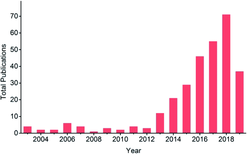 | ||
| Fig. 1 Total publication results from a search for title “carbon dioxide electrochemical reduction” or “CO2 electrochemical reduction”, refined by topic “copper”, across all databases from 2003 to present at Web of Science. Date: 13th July, 2019. | ||
In this review, we first provide a tutorial guide for conducting EC CO2 reduction experiments. Also, various conditions such as the catalyst state, flow rate and type of electrolyte are specified when comparing studies from different research groups. CO2 electrocatalysts are usually divided into two categories: homogeneous and heterogeneous systems. Some reviews on molecular electrocatalysts have covered the advantages of homogeneous systems.39–43 Readers interested in Cu-based complexes could refer to other work.44–51 Cu-based heterogeneous photocatalysts have been reviewed for direct conversion into solar fuels.52 In contrast to the reviews of Cu-based heterogeneous catalysts reported for EC CO2 reduction (review of Cu-based nanocatalysts,53 review of Cu-binary alloys,54 review mainly focused on theoretical studies, nanostructured Cu and bimetallics55), our review includes a tutorial guide for newcomers, lists the parameters specified by different research groups for comparison (Table 2), summarizes the benchmark activity for special products (Section 3) and covers more types of Cu-based heterogeneous electrocatalysts. Different types of Cu-based heterogeneous electrocatalysts, including film and power systems, will be discussed in five main categories: (1) morphology. Morphology control allows us to improve the catalytic activity by tailoring the structure of active sites and increasing the surface area/number of active sites. (2) Oxide-derived Cu. One recent method to enhance CO2 reduction is the oxidation and subsequent reduction of Cu. CuxO formed by annealing, electrodeposition, Cl− and plasma induction all exhibited improved performance for EC CO2 reduction after in situ or ex situ redox processes. (3) Bimetallic species. Alloys are known to be able to tune the geometric and electronic properties of their parent metals. A bifunctional interface (separated composite) without forming an alloy could also improve the performance of each metal while showing fewer changes to the intrinsic electronic properties. The synergistic effects between different metals could create novel catalytic properties. (4) Surface modification. Modification with inorganic species to enhance durability and organic ligands to capture key intermediates is another strategy to improve the performance of Cu-based electrodes. (5) Supports. Supports or substrates are critical to uniformly deposit the catalyst and create novel catalytic features at the interface. Following these sections, as shown in Fig. 2, the electrolyte effects and the overall reaction systems coupling CO2 reduction and H2O oxidation will be discussed for Cu-based heterogeneous electrocatalysts.
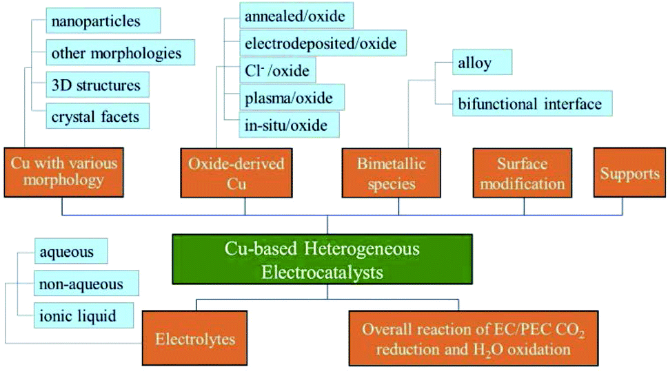 | ||
| Fig. 2 Diagram of the structure of this review. | ||
2. A note on conducting EC CO2 reduction
Conducting EC CO2 reduction may be difficult for many newcomers. A slight oversight will result in the failure of the experiment. Here, we introduce several considerations for conducting EC CO2 reduction experiments, including pre-treatment of the electrolyte, pre-treatment of the electrolysis cell, flow rate of CO2 gas and the electrolyte, electrolysis cell type and product analysis.2.1 Pre-treatment of electrolyte
The purpose of electrolyte pre-treatment is to remove any metallic contaminants that might be present. The deposition of metal ion impurities will poison the electrocatalytic activity and cause the deactivation of the Cu electrode.43,56 This may be also the reason why some beginners observed that almost all the products are H2. Proper operation could suppress H2 evolution, a competing reaction accompanying EC CO2 reduction.Pre-electrolysis of the electrolyte is one method, in which two platinum gauzes could be used as the working and counter electrodes in a two-electrode configuration and a negative cathodic potential was applied for certain period (e.g. −2 V for 24 h,57,58 Pt black cathode at 0.025 mA cm−2 for more than 15 h (ref. 34)). The electrolyte could be also purified by electrolysis between two graphite rods,59 or two high purity Ti foils (99.99%).60 Here, the electrodes used should be of high purity and should be removed from the solution before pre-electrolysis stops to avoid recontamination of the electrolyte caused by the dissolution of electrodeposited impurities on the electrode.
Another method is treating the electrolyte with an ion exchange resin (e.g. Chelex).61–63 Generally the ion exchange resin was stirred with the electrolyte for at least 24 h to minimize the concentration of transition metal impurities. During electrolysis, trace metal ions coordinated in situ with ethylenediaminetetraacetic acid (EDTA) or ex situ with solid-supported iminodiacetate resin should also be considered.62
2.2 Pre-treatment of electrolysis cell
The purpose of cell pre-treatment is similar to that of electrolyte pre-treatment. Normally the electrochemical cell should first be cleaned with strong acid and finally boiled with de-ionized water (18.2 MΩ cm). For example, it could be sonicated in 20 wt% HNO3 for 1 h,64 cleaned in a “nochromix” bath and concentrated HNO3 for 1 h respectively,65 cleaned overnight in HNO3,62 or first cleaned by boiling in a mixture of 1![[thin space (1/6-em)]](https://www.rsc.org/images/entities/char_2009.gif) :1 concentrated HNO3 and HSO4 and then boiling in ultra clean water before each experiment.66
:1 concentrated HNO3 and HSO4 and then boiling in ultra clean water before each experiment.66
2.3 Flow rate of CO2 gas and electrolyte
Before the electrolysis experiments, the electrolyte should first be saturated with CO2 gas by bubbling for at least 0.5 h. Newcomers to the field should pay attention to the pH value before and after CO2 bubbling as well as the cation size (e.g. NaHCO3, KHCO3, etc.), since both these parameters have effects on the selectivity of products. The pH of 0.1 M, 0.2 M, 0.3 M and 0.5 M KHCO3 saturated with CO2 is 6.8, 6.9, 7.0 and 7.2 respectively. More information on the electrolyte effect is discussed in Section 5.During electrolysis, there are three types of CO2 gas and electrolyte flow: (1) continuously bubbling CO2 during the process;31,60,62,63,67–84 (2) CO2 bubbling plus flow electrolyte58,85–87 (the CH4/C2H4 ratio could be tuned by varying the CO2 gas and KHCO3 electrolyte flow rates);58 (3) no report of any form of convection at all.33,88
The unit of flow rate is standard cubic centimetres per minute (sccm) or ml min−1. Certain flow rates of CO2 gas were chosen by different research groups, such as 5 sccm,63,67–72 10 sccm,73–76 20 sccm (ref. 60, 77–84) and 30 sccm. The cell design and catalyst itself should also be considered when choosing the flow rate. The Takanabe group73 chose 10 sccm to ensure sufficient CO2 supply to the electrode surface while preventing the catalyst dropping off the electrode by gas bubbles. The Koper group31 investigated the influence of CO2 flow rate on the activity of 3D porous hollow fibre Cu and observed a maximum FE of 75% CO at −0.4 V vs. RHE when flow rate >30 sccm. In a flow setup, the flow rate of the CO2 gas was set to 50 sccm and that of the electrolyte was 100 sccm.85 To suit a specific system, one could also choose to adjust the flow of electrolyte with the applied potential.86
With CO2 gas bubbling, the catholyte could be stirred.62,89,90 The rotating rate also has an influence on the catalyst activity.30 H2 evolution increased and the product selectivity switched from CH4 to CO when the rotating rate was increased, although there was increased availability of CO2 at the electrode surface. This was caused by the enhanced mass transfer of dissolved CO away from the electrode surface and then less adsorbed CO was left for further reduction.90
2.4 Electrolysis cell types
A variety of cells have been reported in the literature, but the most commonly used is a H-type cell. The total number of publications from 2007 to 2017 on selected metal-based electrocatalysts for CO2 reduction in H-cell experiments was 1083, and 21 in continuous flow reactors.91 In a typical H-type cell, two compartments are separated by an activated ion exchange membrane such as a Nafion membrane (e.g. Nafion@117 with 0.180 mm thickness and >0.90 meq g−1 exchange capacity). The Nafion membrane should be activated first, usually by boiling in 3–5 wt% H2O2, DI water, 0.5 M H2SO4 and DI water at 80 °C, respectively, for 0.5–1 h. The working electrode and reference electrode are in the cathode compartment with a CO2 gas inlet and outlet. The counter electrode is in the anode compartment with or without a gas inlet and outlet.2.5 Product analysis
Gas chromatography (GC) with a thermal conductivity detector (TCD) and a flame ionization detector (FID) is a universal method for gas product analysis. FID with a methanizer is normally used to quantify CO, CH4, C2H4 and C2H6, and TCD is used to quantify H2. It is also able to detect a mixture of 100 ppm CO and 100 ppm H2 with TCD, and 50 ppm CH4, 50 ppm C2H4 and 50 ppm C2H6 with FID, as shown in Fig. 3. High performance liquid chromatography (HPLC) and nuclear magnetic resonance (NMR) are used for detecting liquid products. For example, methanol, ethanol, formate and acetic acid products could be quantified by 1D 1H NMR with DMSO as an internal standard (Fig. 4). More detailed information on gas and liquid product detection can also be found in other reviews.92,93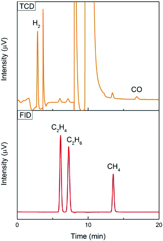 | ||
| Fig. 3 100 ppm CO and 100 ppm H2 tested with TCD, and 50 ppm CH4, 50 ppm C2H4 and 50 ppm C2H6 tested with FID using an online GC system for one-time injection. | ||
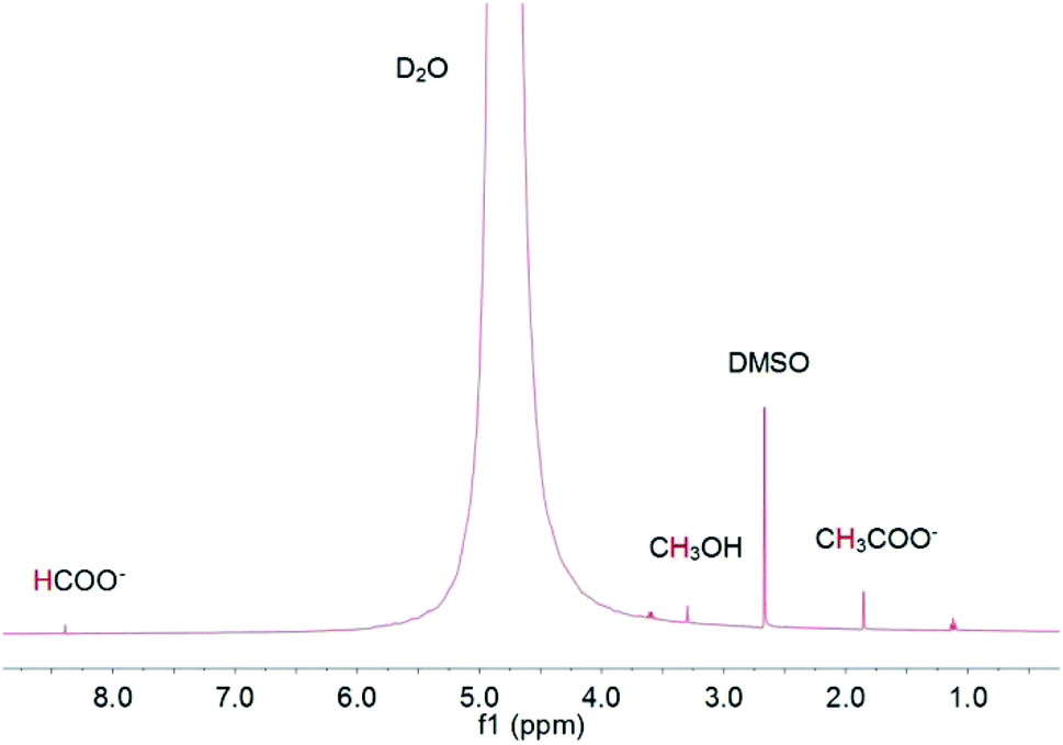 | ||
| Fig. 4 1D 1H NMR analysis of methanol, ethanol, formate and acetic acid products with DMSO as internal standard. | ||
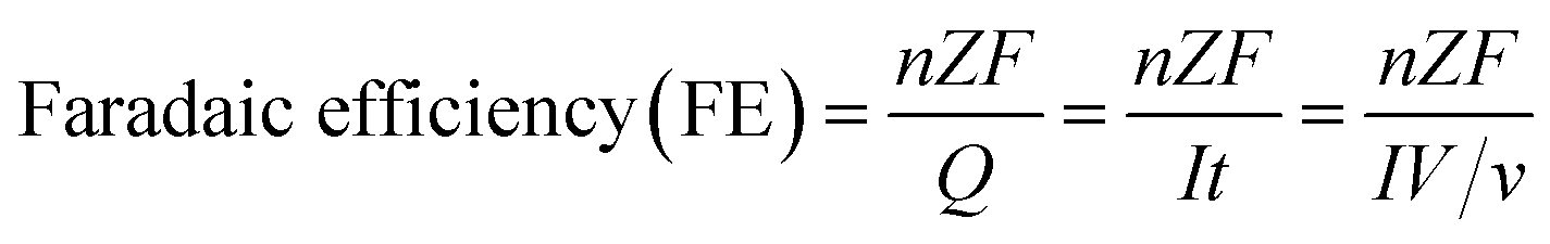
Faradaic efficiency (FE) is the ratio between the amount of product actually detected by an analysis technique such as GC, HPLC or NMR, and the amount of product theoretically formed based on the charge passed during electrolysis. The faradaic efficiency or selectivity for each product in EC CO2 reduction could be calculated according to the following equation:
Without CO2 gas bubbling during electrolysis:
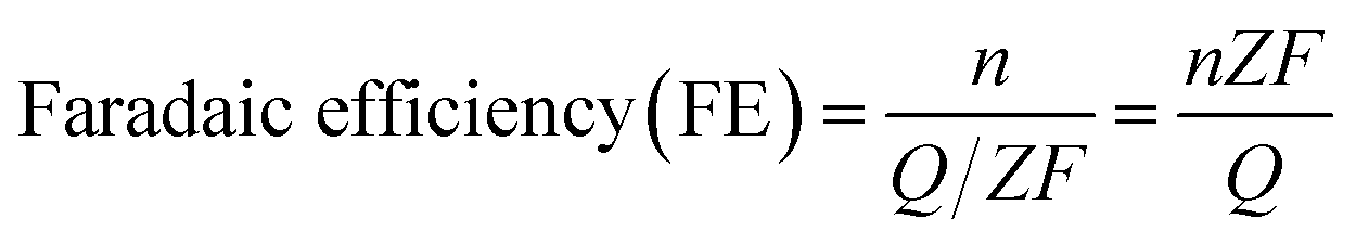 485 C mol−1); Z is the number of electrons required to obtain 1 molecule of the product. As shown in Table 1, the number of electrons required to form 1 molecule of CO, CH3OH, CH4, C2H4 and C2H6 is 2, 6, 8, 12 and 14, respectively.
CO2 gas was continuously bubbled during electrolysis (the first and second measurements are not used to calculate faradaic efficiency to ensure that the data is from a system under equilibrium conditions):
As stated, therefore, the most important thing for newcomers before conducting EC CO2 reduction in aqueous electrolyte is the pre-treatment of the reaction system. Otherwise, H2 may be the sole product rather than CO2 reduction products, as the potential needed for water reduction to H2 is less negative than that for CO2 reduction. In addition, attention should be paid to the flow and convection state of CO2 gas and the electrolyte to make sure that all the experiments are conducted under certain conditions for comparison.
3. Significant progress in the study of Cu-based heterogeneous electrocatalysts for EC CO2 reduction
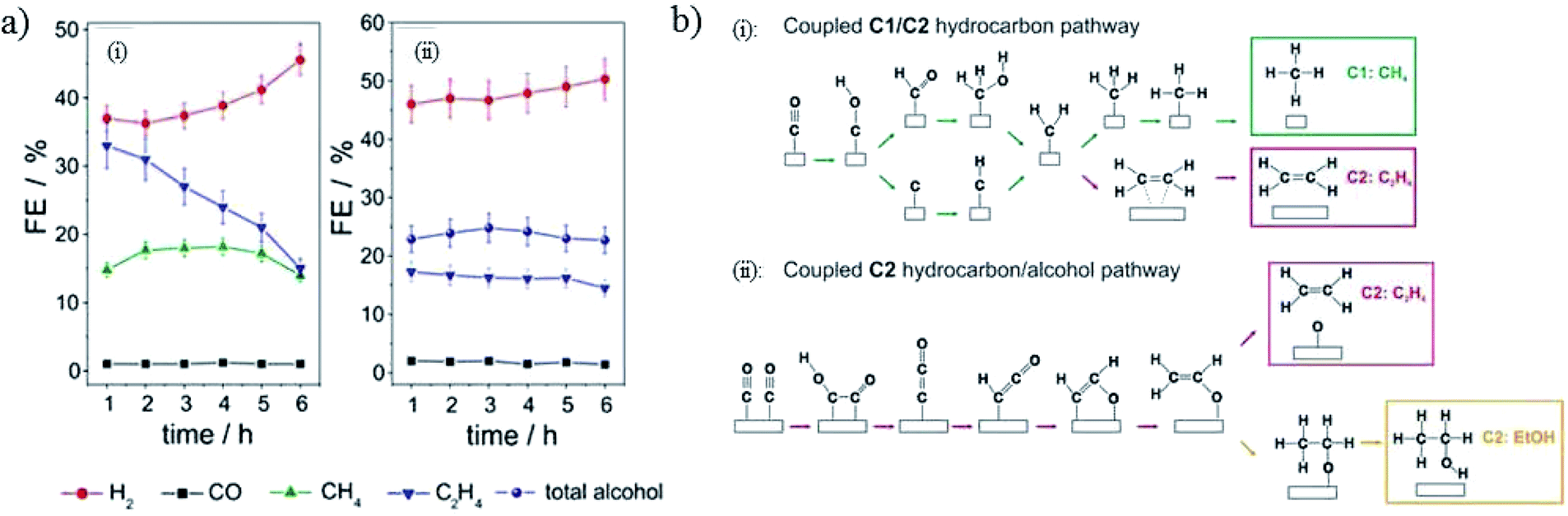
Before a detailed summary and comparison between the work of different research groups, we provide here the benchmark activity of Cu-based heterogeneous electrocatalysts for each EC CO2 reduction product (Fig. 5). Significant progress has been made in C1 and C2 products, whereas the selectivity for C3 and C4 products is relatively low. New insights into the mechanistic study of Cu are also given in Fig. 5 (orange). According to the reported studies, C3+ products are rarely formed and we will focus on the mechanisms for C1 and C2 products. Most mechanisms agree that the first step involves the adsorption/activation of CO2.55,110–113 Various adsorption or activation geometries have been proposed, which are reduced to CO and HCOO−, respectively. The adsorption intermediate on Cu via a carbon or oxygen atom is the key distinction governing the selectivity of CO or HCOO−. Therefore, altering the adsorption site and/or the stability of the adsorption intermediate is crucial for the formation of either CO or HCOO−. On the Cu surface, CO is adsorbed long enough to react further, forming HCHO, CH3OH, CH4 and C2 products. Fig. 6 shows the three most likely pathways from adsorbed *CO. Two pathways have been identified for the formation of C2 products, *CO dimerization for *C(O)(O)C* intermediates at low overpotentials and *CO hydrogenation for *CHO intermediates at high overpotentials. High pH values will favour the major C2H4 pathway (plain red arrows) and low pH value will favour the CH4 pathway (plain blue arrows). Additionally, these intermediates are sensitive to the Cu structure and composition, supports and electrolyte, which will be discussed in detail in the next section.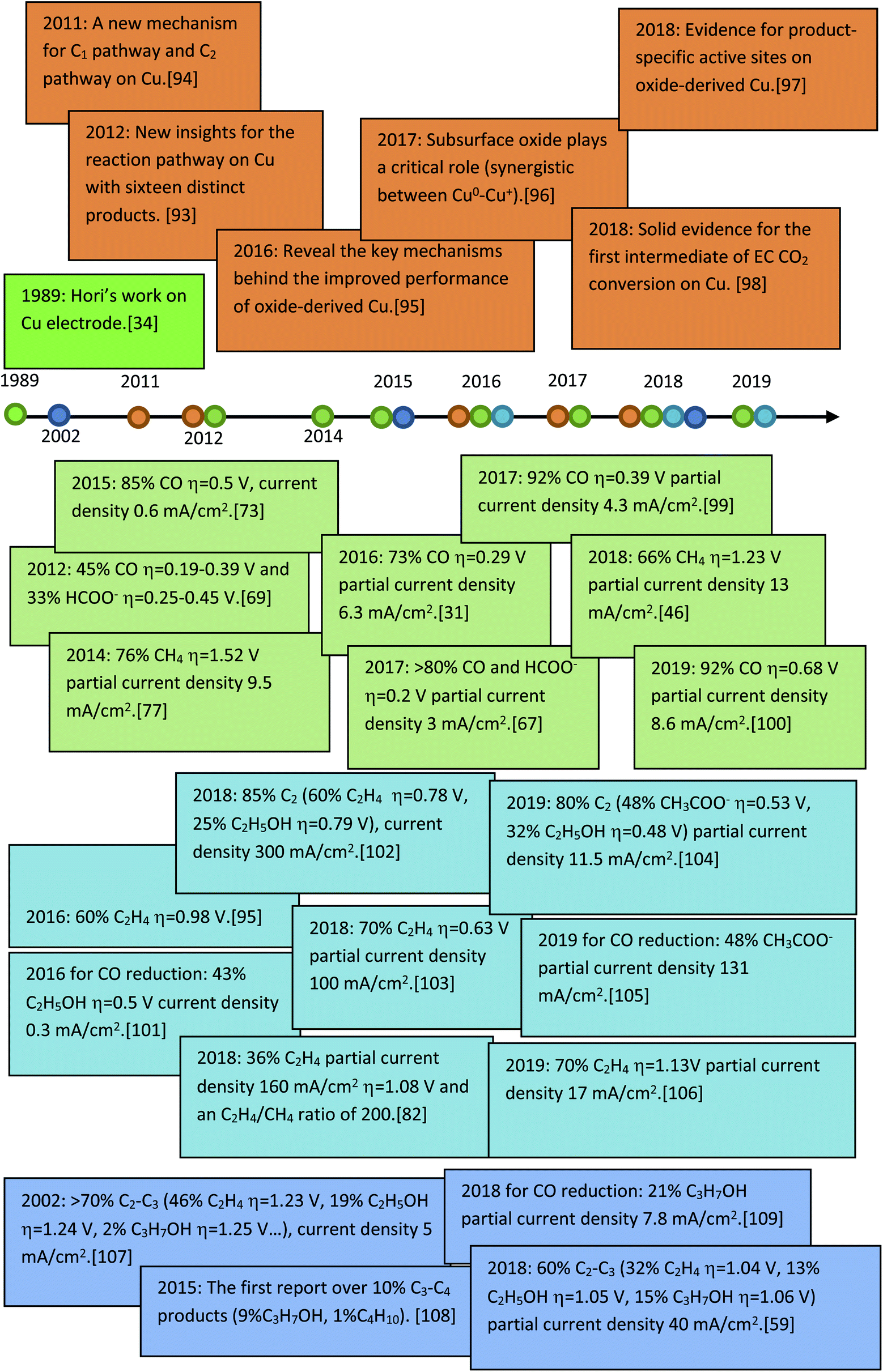 | ||
| Fig. 5 The benchmark activity and progress of mechanism studies on Cu-based heterogeneous catalysts for EC CO2 reduction. | ||
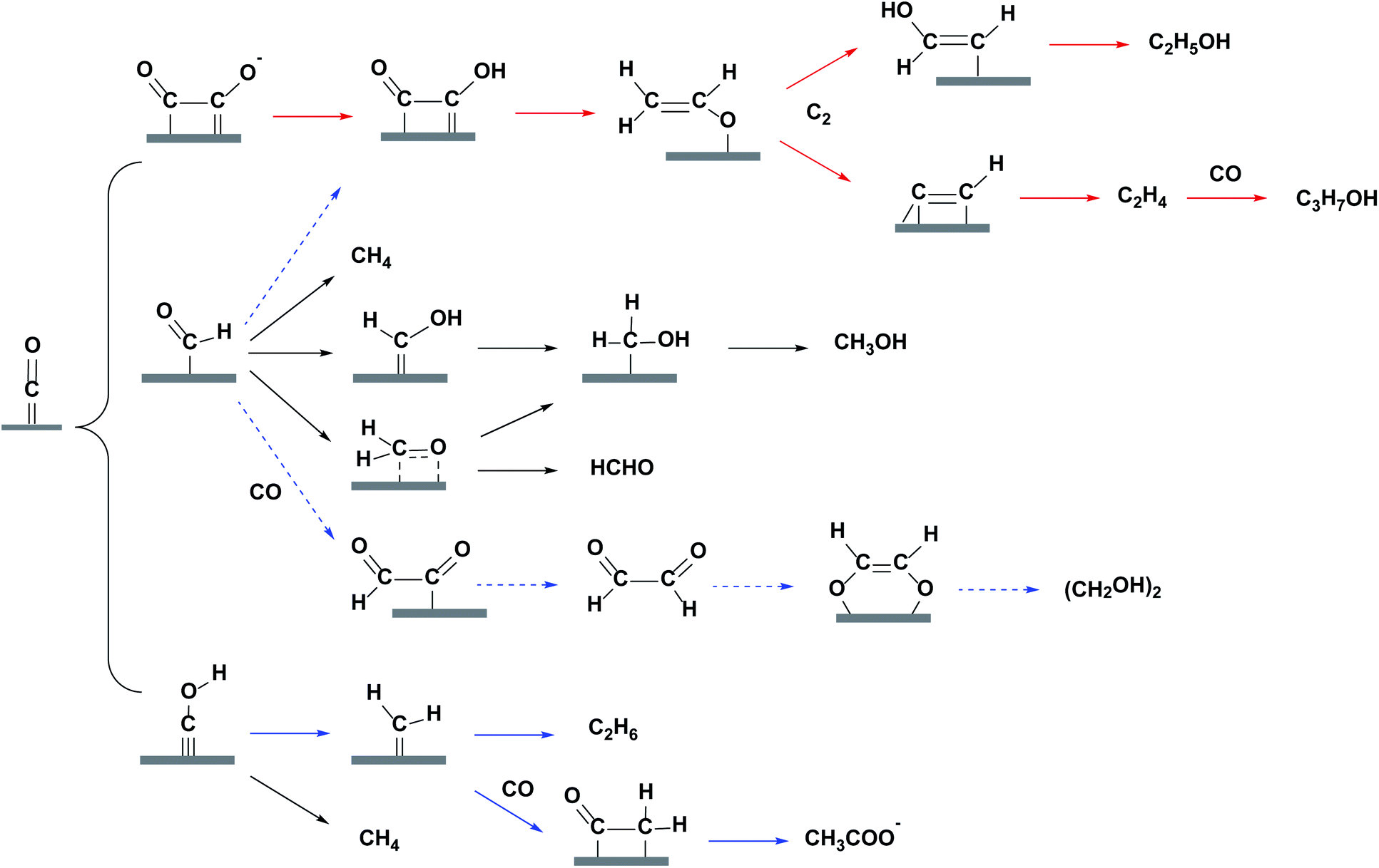 | ||
| Fig. 6 Most likely reaction pathways from adsorbed *CO on Cu surface for C1 and C2 products. Plain red, plain blue and dashed blue routes are for major, minor and trace C2 products. | ||
4. A brief review of Cu-based heterogeneous catalysts for EC CO2 reduction
4.1 Cu with various morphologies
In order to improve the activity of Cu-based electrodes, diverse morphologies have been investigated and developed, including nanoparticles, nanocubes, nanoneedles, and three-dimensional (3D) structures. The relevant surface roughness, size effects, interparticle spacing, nanoparticle loading level and crystal-facets are explored for these various morphologies.Particle size is a critical parameter in tuning the activity and selectivity of Cu nanoparticle catalysts. It may be difficult to control smaller particle sizes and interparticle distances directly via an electrochemical method. Therefore, although powder systems have to be assembled into electrodes for further application in CO2 reduction, many studies have been reported based on Cu powder systems with a controlled small particle size. ∼5 nm Cu nanoparticles embedded in a thin film of metal organic framework (MOF, used to restrict the particle size) on fluorine-doped SnO2 (FTO) exhibited 31% (major HCOO−, minor CO) CO2 reduction selectivity at −0.82 V vs. RHE (0.1 M NaClO4, pH = 4.6).116 B. R. Cuenya, P. Strasser and co-workers65 prepared Cu nanoparticles with a mean size range of 2–15 nm on glassy carbon. The hydrocarbon production decreased as the particle size decreased and vanished for sizes ≤2 nm, as shown in Fig. 7a. Cu nanoparticles (12 nm, 19 nm, 24 nm, 37 nm)/four types of carbon support also showed higher C2H4/CH4 production than smooth copper film, and smaller particle sizes were more favorable for C2H4 formation (pH = 6.8).117 These individual studies give different trends for product distribution, probably caused by different preparation methods, supports and pH of the electrolytes.
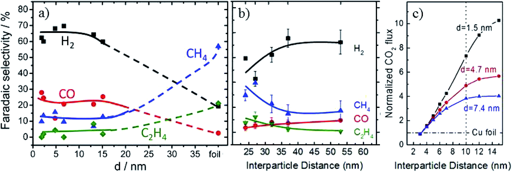 | ||
| Fig. 7 (a) The faradaic efficiency of reaction products during EC CO2 reduction on Cu nanoparticles. (b) The faradaic efficiency as a function of interparticle distances over 4.7 nm Cu nanoparticles. (c) CO2 flux obtained for Cu nanoparticles with different sizes and interparticle distances based on diffusion equations. Experimental conditions: 0.1 M KHCO3, –1.1 V vs. RHE, 30 sccm CO2. Reproduced from ref. 65 for (a) and ref. 119 for (b) and (c), with permission from the American Chemical Society, 2014 and 2016. | ||
Another critical parameter for Cu nanoparticle catalysts is the interparticle spacing.118 B. R. Cuenya and co-workers119 designed 1.5 nm, 4.7 nm and 7.4 nm Cu nanoparticles with interparticle distances of 10–22 nm, 24–53 nm and 41–92 nm, respectively. Smaller interparticle spacing was favorable for re-adsorption of the CO intermediate and its further reduction to hydrocarbons, and with the increase of interparticle spacing the CO2 flux increased, as shown in Fig. 7b and c. P. Strasser and co-workers120 also showed that C2H4 selectivity could be tuned by particle density caused by diffusional interparticle coupling that controlled CO desorption/re-adsorption and in turn the effective COad coverage. Recently, it was also reported that stacked small Cu nanoparticles could be formed by in situ electrochemical fragmentation during the CO2 reduction, promoting C–C coupling reaction.121
The Cu nanoparticles loading level also has a significant influence on the morphology evolution and product selectivity.77 P. D. Yang and co-workers122 assembled densely packed Cu nanoparticles (6.7 nm) on carbon paper electrode. These densely packed nanoparticles changed to cube-like structures intermixed with smaller nanoparticles (Fig. 8a). Compared with spatially separated nanoparticles and ex situ prepared nanocubes, the in situ formation of cube-like particles from densely packed nanoparticles suppressed C1 products and improved C2–C3 formation (C2H4, C2H5OH, and n-C3H7OH 50% at −0.75 V vs. RHE, Fig. 8b).
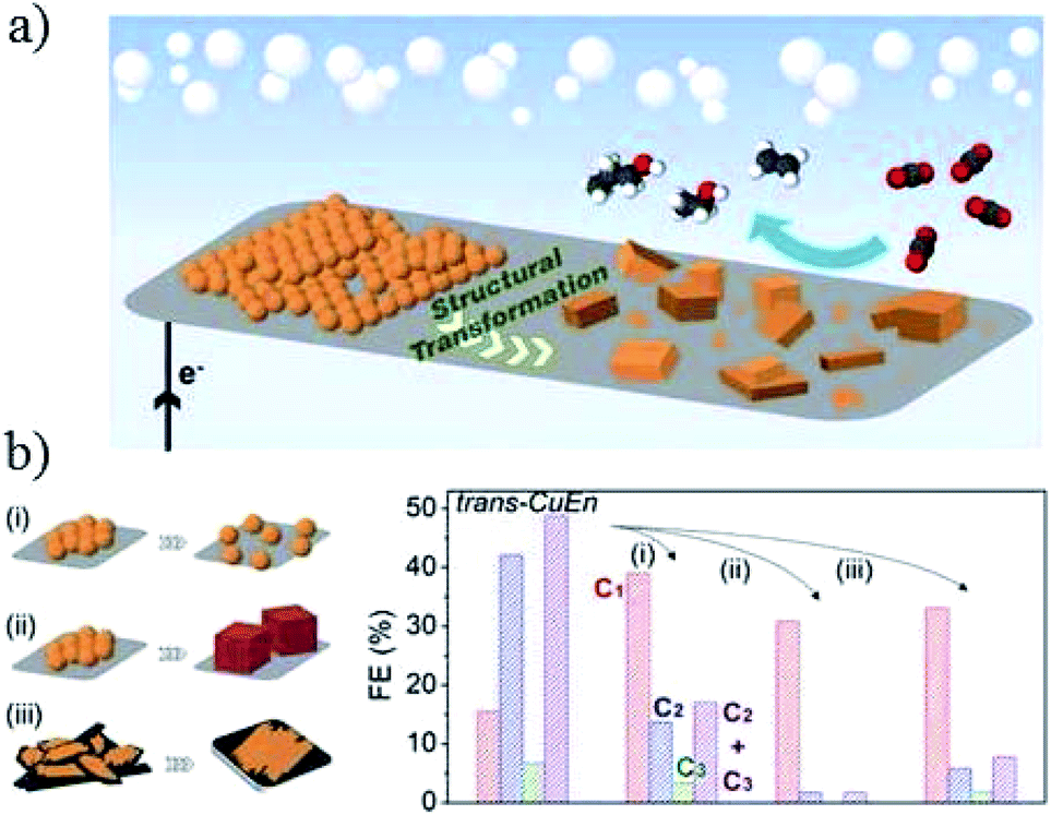 | ||
| Fig. 8 (a) Schematic illustration of Cu nanoparticle ensembles as an active catalyst for C2–C3 product formation. (b) Investigation of the parameters affecting structural transformation of Cu nanoparticle ensembles and their catalytic activity. (i) Separation of the NPs from their initial densely packed assembly, (ii) use of Cu nanocubes as starting materials, and (iii) change of support to a low surface area carbon plate. Experimental conditions: 0.1 M KHCO3, (i) −0.84 V, (ii) −0.86 V, and (iii) −0.81 V vs. RHE, respectively. Reproduced from ref. 122. | ||
Therefore, small interparticle distances and densely packed nanoparticles would lead to higher hydrocarbon formation. The above Cu nanoparticles are crystalline in form. Compared with the crystalline form, the amorphous form seems to be more favourable for C2 products. J. M. Yan and co-workers78 synthesized amorphous Cu nanoparticles (average size 3.3 nm), and achieved 37% HCOOH and 22% C2H5OH at −1.0 V vs. RHE (0.1 M KHCO3, 20 sccm CO2). The crystalline Cu nanoparticles (average size 3.4 nm) only showed 26% HCOOH and no C2H5OH at the same potential. They ascribed the enhanced activity to the high electrochemically active surface area (ECSA) and CO2 adsorption on the amorphous surface.
Similar to Cu nanoparticles formed on film in situ as an electrode, the morphology of powder nanoparticles could also have an effect on product selectivity, and a surface morphology with more defects and boundaries promotes C2 products. Star decahedron Cu nanoparticles123 and branched CuO nanoparticles106 are reported to achieve high faradaic efficiency of ethylene (C2H4) up to 52% and 70% at −1.0 V vs. RHE, respectively.
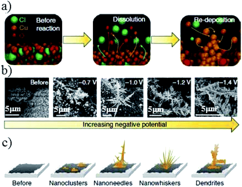 | ||
| Fig. 9 (a) Schematic of the electrogrowth process of Cu from Cu2(OH)3Cl. (b) Corresponding SEM images and (c) structure evolution of the key structural features after applying various potentials for at least 1 h in 0.1 M KHCO3. Reproduced from ref. 82 with permission from Springer Nature, 2018. | ||
Similar trends in the role of morphology are observed for nanocube structures in powder systems, especially for C2H4 production. R. Buonsanti and co-workers129 fabricated different sizes of Cu nanocrystal spheres (7.5 nm and 27 nm) and Cu nanocrystal cubes (24 nm, 44 nm, and 63 nm). There was a monotonic size-dependent trend for both shapes – the smaller, the more active. Cube-shaped copper nanocrystals showed better performance than spheres. The overall CO2 reduction activity changed from 50% to 80% and 63% for 24 nm, 44 nm, and 63 nm, respectively, and the highest faradaic efficiency of C2H4 was 41% for 44 nm nanocubes at −1.1 V vs. RHE (Fig. 10). Edges and Cu(100) were responsible for maximizing C2H4 selectivity. However, edges were also reported to promote CH4 selectivity in nanowire structures. P. D. Yang and co-workers130 prepared ultrathin (∼20 nm) 5-fold twinned Cu nanowire on carbon black/glassy carbon plates. The catalyst could achieve 55% CH4 at −1.25 V vs. RHE with <5% other CO2 reduction products, likely due to the high density of edge sites. With the evolving morphology, CH4 decreased and C2H4 increased. Wrapping Cu nanowires with graphene oxide could prevent morphology changes and in turn prevent the decrease of CH4 selectivity.
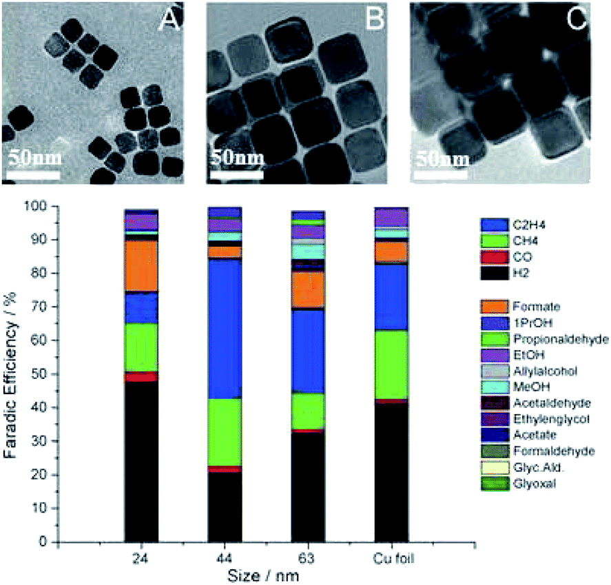 | ||
| Fig. 10 TEM images of Cu cubes with an average edge length of 24 nm (A), 44 nm (B), 63 nm (C), and corresponding faradaic efficiency after subtracting the substrate signals. Experimental conditions: 0.1 M KHCO3, −1.1 V vs. RHE, 5 sccm CO2. Reproduced from ref. 129 with permission from Wiley, 2016. | ||
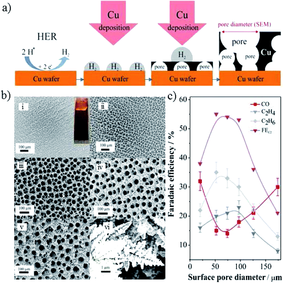 | ||
| Fig. 11 (a) Schematic representation of the key aspects of Cu electrodeposition using H2 as a template. (b) SEM images of Cu foams with different pore sizes on Cu substrate, electrodeposited for different times. (c) The faradaic efficiency of CO2 reduction products for Cu foam with various pore sizes (experimental conditions: 0.5 M NaHCO3, −0.8 V vs. RHE). Reproduced from ref. 131 for (a) and (c), and ref. 88 for (b) with permission from the American Chemical Society, 2014 and 2016. | ||
In addition to pore sizes on the micron scale, nano-porous structures could also change the local pH and retention time of key intermediates133,135 and, in turn, the product selectivity. Using a sputtering method on anodized aluminium oxide, as shown in Fig. 12a, the pore widths and depths of the Cu mesopore electrode could be precisely controlled. Compared with an electrode of 300 nm (width)/40 nm (depth), C2H4 formation was enhanced from 8% to 38% when the pore width was narrowed to 30 nm, whereas the major C2 product changed to C2H6 with a faradaic efficiency of 46% when the depth was increased to 70 nm at −1.3 V vs. RHE (Fig. 12b). A pH change with 3D morphology was also reported by other groups. Using Cu foil with a mixed solution of (NH3)2S2O8 and NaOH for different times, W. A. Smith and co-workers134,136 obtained Cu(OH)2 nanowires with various lengths and densities. The nanowires with high lengths and densities had an influence on the diffusion of HCO3−, leading to a high local pH, since HCO3− can neutralize OH− (HCO3− + OH− → CO32− + H2O), as shown in Fig. 12c. With higher lengths (≥2.4 ± 0.56 μm), n-C3H7OH was detected along with CO, HCOOH and C2H4. For even higher lengths (≥7.3 ± 1.3 μm), C2H6 and C2H5OH could be formed. In summary, high lengths or depths of 3D nanostructures favor higher hydrocarbon formations.
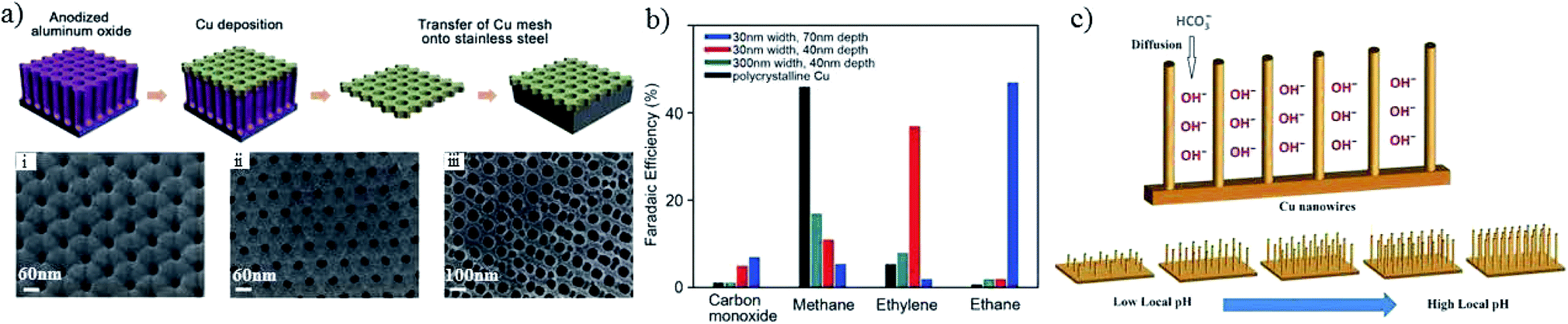 | ||
| Fig. 12 (a) Scheme of Cu mesopore electrode preparation and corresponding SEM images; (i–iii) are 30 nm/40 nm, 30 nm/70 nm and 300 nm/40 nm width/depth, respectively. (b) The faradaic efficiencies of CO2 reduction products for the prepared Cu mesopores. Experimental conditions: 0.1 M KHCO3, −1.3 V vs. RHE. (c) Schematic illustration of the diffusion of electrolytes into Cu nanowire arrays. Reproduced from ref. 133 for (a) and (b), and ref. 134 for (c) with permission from Wiley, 2016. | ||
 | ||
| Fig. 13 Schematic illustration of reaction pathways on Cu(100) and (111) single crystals. Reproduced from ref. 138 with permission from the American Chemical Society, 2016. | ||
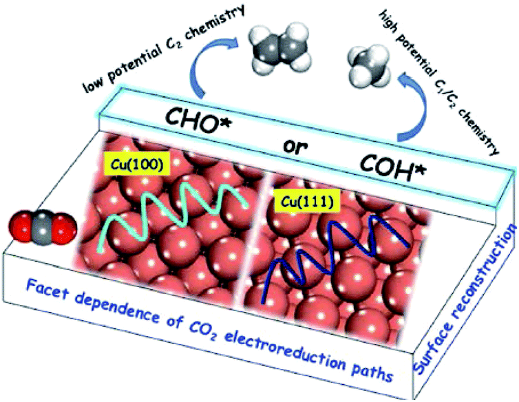
B. S. Yeo and co-workers141 studied Cu2O (hydrothermally prepared)-derived Cu and Cu single-crystal surfaces. Of the three single-crystal surfaces (100), (111) and (110), Cu(100) exhibited the lowest energy barrier for the dimerization of CO*. A. Nilsson and co-workers157 investigated single crystal copper (100), (111), and (211) for comparison with Cu nanocubes. The (100) surface was the most comparable to the Cu nanocube surface in terms of C2H4 production, whereas CH4 was not suppressed. One possibility is that it has the ideal terrace length or active sites for C2H4 formation. K. Chan, H. T. Wang and co-workers59 galvanostatically cycled Cu foil in Cu(NO3)2 to obtain a Cu2O nanocube layer with smooth (100) facets on the surface. They also suggested that Cu(100) and stepped (211) facets favored C2+ products over Cu(111). From the present results, Cu(100) crystal facets favor C2+ products compared with other facets for most reported systems.
As stated above, understanding the effects of Cu morphology on the selectivity is highly complex since there is a combined effect of properties, such as low-coordinated sites, catalyst density or dispersion, CO2 flux and electrical double layers in the electrolyte, on the activity of CO2 electrochemical reduction. Although there is wide variation in the activity trends for Cu with various morphologies, the selectivity for possible products may be adjusted by tuning the particle size and interparticle spacing/particle density of Cu nanoparticles/nanocubes, tuning the pore size and depth/length of 3D structures, or tuning the energy facets of Cu crystals. In addition, attention should be paid to morphology evolution during the electrochemical CO2 reduction process.
4.2 Oxide-derived Cu electrocatalysts
Recently, oxide-derived Cu has drawn much attention in electrocatalytic CO2 reduction. Various oxide-derived Cu electrocatalysts have been designed and the mechanisms involved have been discussed widely. Some groups68–71,142,143 suggest that grain boundaries are the active sites. Some groups80,144,145 believe that low-coordinated atoms act as active sites. There are also many groups85,114,146–148 which believe that the active phase is metallic Cu0 since there is a significant driving force for Cu2O reduction under CO2 reduction conditions. Many groups82,95,149,150 proved that the Cu+ site is key for enhanced activity and remained on the catalyst surface during the reaction. Some groups96,151,152 found that sub-surface oxygen stabilized in reduced oxide-derived Cu plays an important role and there is synergy between surface Cu+ and surface Cu0 sub-oxide species.Although the true active site is still under debate, oxide-derived Cu has shown excellent performance in decreasing the potential required and enhancing selectivity for specific products. Most recent reports also confirmed that two (Cuδ+ and Cu0) were better than one.100,154 In this section, we will discuss oxide-derived Cu in detail based on the fabrication process, including annealed/oxide-derived Cu, electrodeposited/oxide-derived Cu, Cl−/oxide-derived Cu, plasma/oxide-derived Cu, and in situ/oxide-derived Cu. Since the wide variation in experimental conditions results in various results for similar materials, detailed experimental conditions are included for different groups.
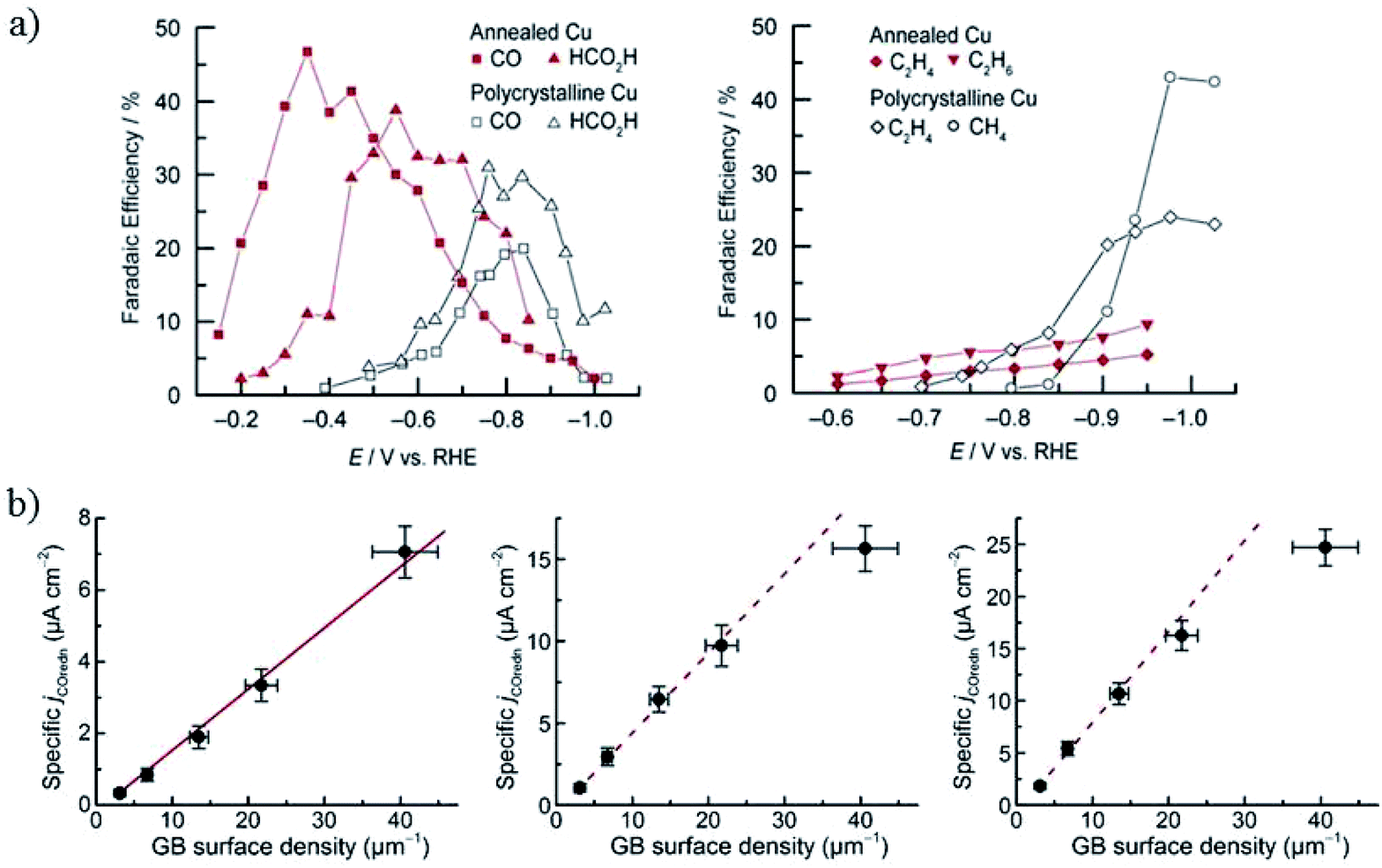 | ||
| Fig. 14 (a) The faradaic efficiency of CO2 reduction products for annealed Cu and polycrystalline Cu foil. 0.1 M NaHCO3, 5 sccm CO2. (b) The specific current density of CO reduction versus the grain boundary density at −0.3 V, −0.4 V and −0.5 V, respectively. Reproduced from ref. 69 for (a) and ref. 71 for (b) with permission from the American Chemical Society, 2016. | ||
Higher temperature annealing forms both Cu2O and CuO nanowires and the corresponding derived Cu also exhibits superior performance for CO2 reduction. C. Wang and co-workers80 annealed Cu gauze in air at 600 °C to get CuO nanowires (with Cu2O present inside the nanowires) with a diameter of 50–100 nm and length of 10–50 μm. Then they obtained high density Cu nanowires by electrochemical reduction (ECR) or forming gas reduction (FGR). The Cu nanowires obtained via the ECR method exhibited a higher surface roughness and a thin surface layer of Cu2O nanocrystals less than 10 nm, while FGR led to larger Cu crystal segments (>100 nm size) without Cu2O present on the surface. At low overpotentials (−0.3 V to −0.5 V vs. RHE), the total faradaic efficiency of CO and HCOOH was as high as 70–80% for ECR nanowires, whereas H2 was the dominant product for Cu gauze and FGR nanowires (0.1 M KCHCO3, 20 sccm CO2). They ascribed the high activity to the high-density grain boundaries and low-coordinated surface sites associated with the small crystalline features, as well as more open facets (e.g. (100) and (211)) on the surface. Later studies by C. Wang, T. Mueller and co-workers144,145 further suggested that the high activity and selectivity of the ECR nanowires could be ascribed to the (110) surface, high-angle grain boundaries, or some closely related metastable surface feature. Pre-reduction of annealed Cu in different solutions led to different activities, as also reported by J. J. Zhang’s group.155 Reduction of annealed Cu in 1 M NaOH formed only a layer of nanofibers with 30–100 nm diameters, whereas in 1 M H3PO4 the nanofibers were surrounded by kernels and achieved 43% HCOO−, which was much higher than for the pre-reduced annealed Cu in NaOH (1% HCOO−) in 0.5 M KHCO3.
Summarizing the above reports, the annealed/oxide-redox method could enhance the selectivity and lower the overpotential required for HCOO− and CO during CO2 reduction, while promoting the selectivity of C2+ products during CO reduction.
With related mechanism studies on enhanced HCOO− and CO formation, using ambient pressure X-ray photoelectron spectroscopy interpreted with quantum mechanical predictions of the structures and free energies, W. A. Goddard III, J. Yano, E. J. Crumlin and co-workers96 showed that the presence of sub-oxide species below the Cu surface played a crucial role in the adsorption and activation of CO2 on annealed/oxide-derived Cu. This thin layer of sub-oxide was essential for converting chemisorbed CO2 in the presence of H2O as the first step toward CO2 reduction products such as HCOO− and CO. Quantum mechanical calculations and experimental results also showed that there was an optimized amount of subsurface oxide. More or none at all would destabilize the bent (chemisorbed) CO2. (1) In the case of Cu(111) without subsurface oxide (Fig. 15a), the C atom of CO2 was chemically bonded to a Cu0. One of the O atoms was stabilized by hydrogen bonding to H2Oad on another Cu0. (2) When the subsurface oxide was increased to 1/4 ML (Fig. 15b), the C atom was chemically bonded to two surface Cu0. One O atom was chemically bonded to one Cu0, and the other O atom was stabilized by the Cu+ pulled up by H2Oad. (3) When the subsurface oxide was increased to 1/2 ML (Fig. 15c), the C atom was chemically bonded to a Cu+ that shares one O atom stabilized by hydrogen bonding to H2Oad on another Cu+. Later they153 found that only surface Cu+ itself could not improve the performance of CO2 reduction, and proposed Cu metal embedded in an oxidized matrix model as a partially oxidized Cu surface, where the synergy between the surface Cu+ and surface Cu0 was responsible for CO2 activation.
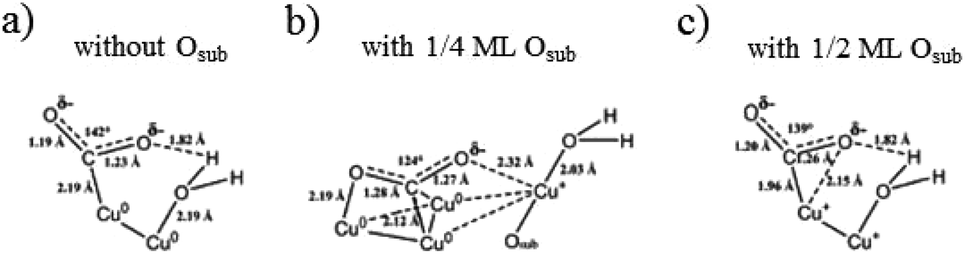 | ||
| Fig. 15 Predicted structures for chemisorbed-CO2 with H2O on Cu(111) with different levels of subsurface oxide Osub: (a) 0 ML, (b) 1/4 ML and (c) 1/2 ML Osub. Reproduced from ref. 96. | ||
 | ||
| Fig. 16 (a) The faradaic efficiency of CO2 reduction products for electrodeposited Cu(I) and annealed Cu(II). (b) Proposed schemes for electrodeposited and annealed samples. Experimental conditions: −1.1 V vs. RHE, 0.5 M KHCO3. Reproduced from ref. 156 with permission from the American Chemical Society, 2017. | ||
There is a dependence of CO2 activity on film thickness for electrodeposited Cu2O film. J. Baltrusaitis, G. Mul and co-workers72 electrodeposited Cu2O film on a Cu plate. A C2H4/CH4 ratio of ∼8–12 was observed for thin film at −1.1 V vs. RHE, with a larger amount of CH4 for thicker film (0.1 M KHCO3, 5 sccm CO2). B. S. Yeo and co-workers81 electrodeposited Cu2O film with different film thicknesses on Cu discs. A maximum of 34–39% C2H4 with a ratio of C2H4/CH4 up to 100, and 9–16% C2H5OH was obtained at −1.0 V vs. RHE, as shown in Fig. 17a. Then they146 prepared Cu2O- and CuO-derived Cu with different thicknesses via a hydrothermal method (1.3 and 11.5 μm). In contrast to other works proposing the protonation of C2H4, they showed that C2H6 and C2H5OH were likely to form via the dimerization of –CH3 intermediates on thick oxide-derived Cu (Fig. 17b). They observed that Cu2O was rapidly reduced to metallic Cu during CO2 reduction by using in situ Raman spectroscopy. The surface reoxidized in tens of seconds after the cathodic potential was removed. This is in contrast to the Lee group’s150 work on electrodeposited Cu2O/GDE, where they found that Cu2O was only partially reduced on the basis of ex situ XRD and Auger electron spectroscopy. Later again, the Yeo group only observed signals belonging to CO adsorbed on Cu metallic sites rather than oxide sites for electrodeposited CuxZn.84
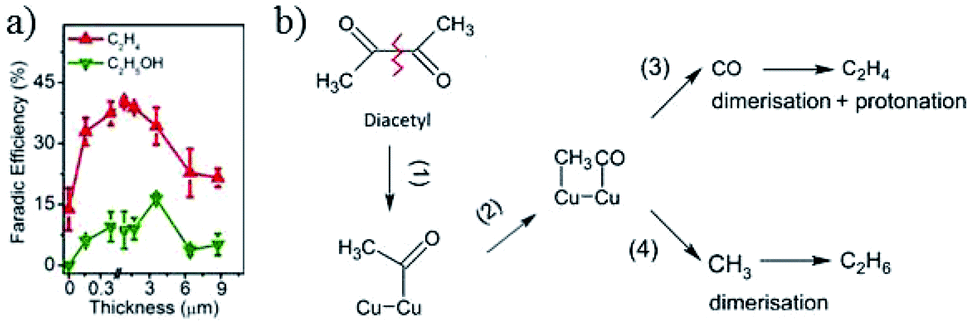 | ||
| Fig. 17 (a) The faradaic efficiency of C2H4 and C2H5OH versus the thickness of electrodeposited Cu2O. (b) Proposed mechanism on thick oxide-derived Cu and thin oxide-derived Cu, respectively. Experimental conditions: −1.0 V vs. RHE, 0.1 M KHCO3, 20 sccm CO2. Reproduced from ref. 81 for (a) and ref. 146 for (b) with permission from the American Chemical Society, 2015 and 2017. | ||
 | ||
| Fig. 18 (a) Proposed mechanism of Cu nanoparticle growth during electrochemical cycling in the presence of Cl−. (b) Rapid oxidation of Cl−/oxide-derived Cu with a high abundance of grain boundaries. Reproduced from ref. 142 for (a) and ref. 143 for (b) with permission from Wiley, 2016 and 2017. | ||
In contrast to the Nilsson group’s study157 and the Yeo group’s study,159 J. Lee and co-workers160 observed the preferential formation of multicarbon fuels, especially n-C3H7OH (the first report over 10% C3–C4 products, 0.1 M KCl), using in situ prepared Cl−-induced bi-phasic Cu2O–Cu. They also found that the catalyst exhibited relatively higher Cu+ coverage than oxide-derived Cu and the use of a KCl electrolyte could prolong the preservation of the Cu2O phase compared to a KHCO3 electrolyte.
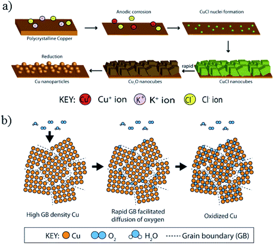
A. T. Bell, J. W. Ager and co-workers142 electrochemically cycled copper foil in the presence of halide anions KF, KCl, KBr, and KI. They observed an enhanced faradaic efficiency for C2H4 and C2H5OH (excluding KF). Their observation of C2H5OH was in contrast to the Nilsson group and Yeo group studies. Without electrochemical cycling in halide anions, the product distribution was not significantly changed even with the addition of halide anions in electrolyte for CO2 reduction. In situ Raman spectroscopy and SEM showed that during the oxidation sweep, anodic corrosion formed a Cu2O layer, which consisted of cubic crystals ∼150 nm. CuCl formed cubes when precipitated in the solution at pH > 4. In neutral and basic solutions with a low Cl− concentration, CuCl could convert to Cu2O. During the reduction sweep, irregular Cu nanoparticles (ca. 20 nm in diameter) with rounded edges were formed (Fig. 18a). They ascribed the enhancement in C2H4 formation to a large number of (100) facets (similar to the Nilsson group) and the formation of grain boundaries and defects (similar to the Kanan group). Later they64 also investigated four types of oxide-derived Cu electrocatalysts: “oxide-derived nanocrystalline Cu” developed by the Kanan group, “Cu nanowire arrays” developed by the Smith group, “electrodeposited Cu2O films” developed by the Yeo group, and “electrochemical oxidation–reduction cycled Cu” developed by the Nilsson group. There was an optimal roughness factor for the oxide-derived layers to have a high local pH and maintain a high concentration of dissolved CO2. More recently, J. W. Ager and co-workers143 prepared 18O-enriched oxide-derived Cu by cycling Cu foil in the presence of KCl in H218O. The selectivity of C2 and C3 products in 0.1 M KHCO3 was up to 60%. By analysis with ex situ secondary-ion mass spectrometry (SIMS), they found that <1% of the original 18O content remained in the sample after the CO2 reduction reaction and believed that the grain boundary was more likely responsible for the high activity, as proposed by the Kanan group. Similarly to the Yeo group, they also observed the rapid re-oxidation of oxide-derived Cu with in situ Raman spectroscopy. They believed that this rapid re-oxidation was possibly due to the grain boundaries (Fig. 18b), since Cu film with fewer grain boundaries did not oxidize quickly.
E. H. Sargent and co-workers82 applied constant potential in CO2-saturated 0.1 M KHCO3 to reduce Cu2(OH)3Cl precursor on carbon paper. This dissolution and electro-redeposition process could form Cu2O nanoneedles, which exhibited excellent activity for C2H4 formation (partial current density 160 mA cm−2) with a ratio of C2H4/CH4 of up to 200 at −1.0 V vs. RHE (20 sccm CO2). For the first time, they used in situ Cu L-edge XAS to demonstrate that the Cu+ surface species could direct C2+ product selectivity. The process of Cu2+ to Cu+ was quick (within 5 min), while Cu+ to Cu0 was much slower, and 23% Cu+ surface species still remained after 1 h electrolysis at −1.2 V vs. RHE.
In summary, Cl−/oxide-derived Cu shows excellent activity for C2 and even C3–C4 product formation, regardless of whether it is caused by the morphology evolution to nanocubes or the presence of Cu+.
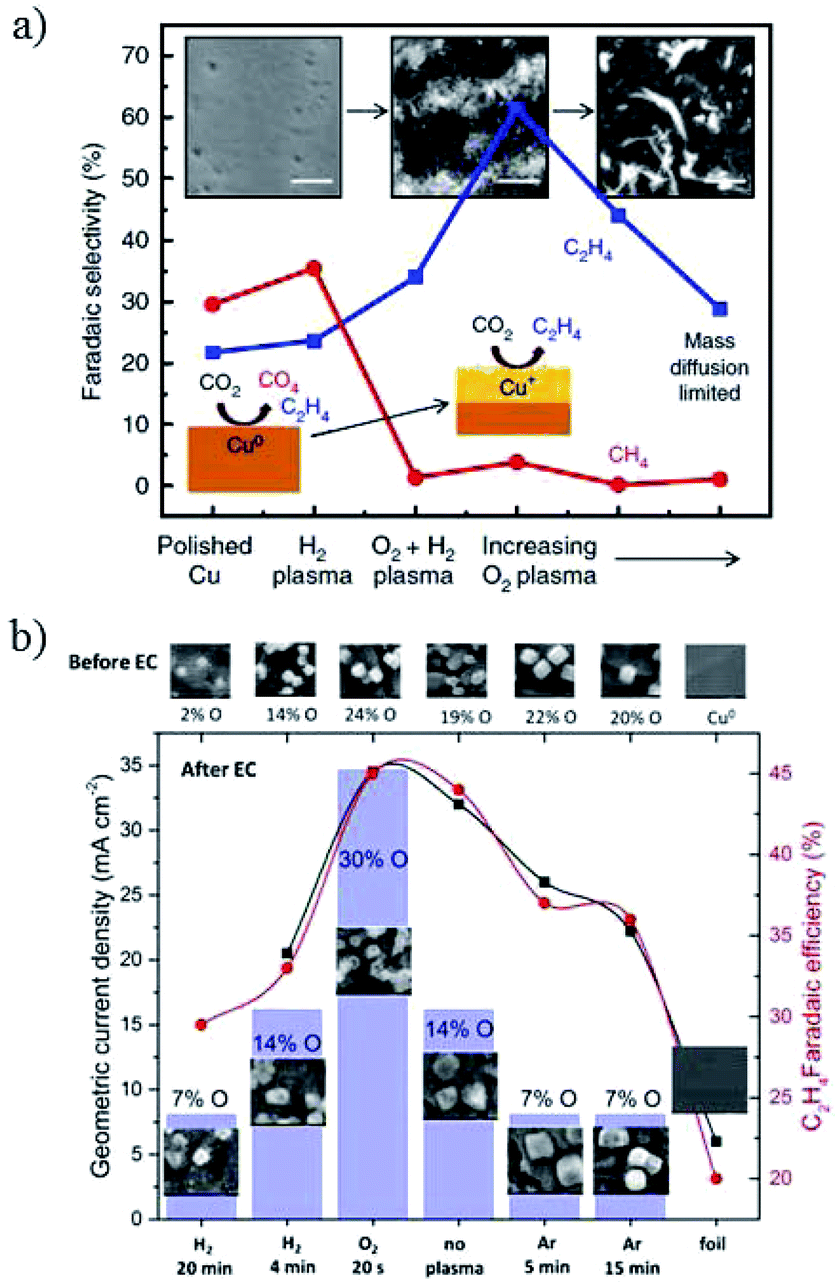 | ||
| Fig. 19 (a) The faradaic efficiency of hydrocarbon products for plasma-treated Cu foil. (b) Current density and C2H4 faradaic efficiency for Cu nanocubes with plasma treatment. Experimental conditions: 0.1 M KHCO3, −1.0 V vs. RHE, 30 sccm CO2. Reproduced from ref. 95 for (a) and ref. 149 for (b) with permission from Springer Nature, 2016, and the American Chemical Society, 2017. | ||
:CO ratio ranged from ∼32:1 to 9:16 for pulse times between 10 ms and 80 ms, respectively (0.1 M KHCO3, 20 sccm). J. Y. Lee and co-workers162 also indicated that Cu2O formed under the anodic cycle in the pulsed electroreduction of CO2 and this process also prevented the poisoning of carbon on the Cu surface. Using pulsed voltammetry, P. Rodriguez and co-workers163 observed that oxygenated products associated to the coverage of OH species on single crystal Cu(100) and Cu(111). In contrast to Spurgeon and co-workers’ work,83 however, the selectivity trend shifted to CH4 and C2H4.
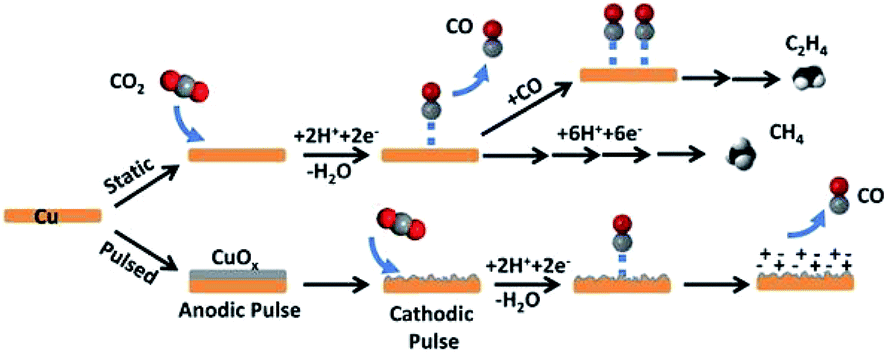 | ||
| Fig. 20 Schematic diagram for CO2 reduction by pulsed-bias method and potentiostatic electrolysis. Reproduced from ref. 83 with permission from the American Chemical Society, 2016. | ||
Early last year, however, I. Chorkendorff, I. E. L. Stephens and co-workers164 investigated CO electroreduction on polycrystalline Cu foil in 0.1 M KOH at low overpotentials from −0.4 to −0.6 V vs. RHE. Compared with oxide-derived nanostructured Cu in the literature, the polycrystalline Cu foil exhibited higher selectivity for C2 and C3 aldehydes and ethylene. This indicated that future studies should focus on the intrinsic activity of Cu.
In summary, for oxide-derived Cu, various methods have been developed for the preparation of a Cu-oxide precursor (Cu2+, Cu+) and for its subsequent redox process (in situ and ex situ, electrochemical and H2 reduction). As stated at the beginning of this part, the true active site of Cu-based electrocatalysts fabricated from oxidation–reduction processes is still under discussion. Using Cu-based electrocatalysts with oxidation–reduction pretreatment, the activity and product selectivity were indeed improved, especially for the ratio of C2H4 and CH4, which has been proven by many research groups as above. Further mechanism investigations may focus on in situ and operando studies to gain more insight into the subsurface oxygen, chemical state or morphology of the CuxO catalyst under CO2 reduction conditions.
4.3 Cu–M bimetallic species
Combining Cu with other metals (M) to form alloys or separated Cu–M composites is another efficient approach to enhance the activity and selectivity for CO2 reduction. In this part, we summarize Cu–M alloys, including pure metallic alloys and oxide-derived alloys, as well as Cu–M bifunctional interfaces (separated Cu–M composites). For pure metallic alloys, the catalytic activity is affected by the nature of the secondary metal atom. Generally, CO selectivity is enhanced for Cu–M (M = In, Zn, Ag, Au) and HCOO− for Cu–M (M = Sn, Pd), while hydrocarbon selectivity increases with increasing Cu atoms in the alloy. When the composition of ordered or separated arrangements is precisely controlled, different behavior will be observed and C2 products could be promoted. When the alloys are formed from oxide species, different behavior could also be observed, especially for oxide-derived blended and separated composites for C2H5OH production. There are electronic and geometric effects for each individual component of the alloy, while the geometric effects play important roles for separated Cu–M composites. Therefore, we may expect distinct performances of Cu–M bimetallic species via precise control of their atom and phase arrangements.:1 with 40 atom% In alloy. K. Takanabe and co-workers73 thermally oxidized a Cu metal sheet to form a hairy CuO nanowire structure on Cu2O–Cu layers. The CuIn electrode was then prepared through in situ electrochemical reduction of the oxide-derived Cu in a mixed solution of InSO4 and citric acid. High efficiency of CO was obtained (>70%) at low overpotential (−0.4 V to −0.7 V vs. RHE), with a maximum of 95% CO at −0.7 V vs. RHE (0.1 M KHCO3, 10 sccm CO2). Similar trends were also observed when using Sn and Zn as the second metals. DFT calculations suggested that In was preferentially located at the edges of the Cu surface (H2 evolution sites are presumably edges) and caused weakened adsorption of H over CO (high-overpotential metal for H2 formation), while the intact Cu corners might be still responsible for CO production. More importantly, there was only a slight improvement in CO selectivity for the Cu–In electrode without initial oxidation treatment of the Cu sheet. They74 also fabricated CuSn alloys using a similar electrodeposition method with initial oxidation. High CO selectivity with FE >90% over a wide potential range of −0.4 V to −0.8 V vs. RHE was achieved. According to their results, to improve the CO selectivity with CuIn or CuSn alloys, initial oxidation could be adopted. C. P. Berlinguette and co-workers67 investigated ternary alloys of Cu–Zn–Sn for CO2 reduction to CO and HCOO−. With an optimized ratio, >80% CO and HCOO− could be achieved with a partial current density of 3 mA cm−2 at an overpotential of 0.2 V (0.5 M NaHCO3, 5 sccm CO2).
E. H. Sargent, P. D. Yang and co-workers89 prepared a Cu-enriched Au nanoneedle electrode via an underpotential deposition (UPD) method with various Cu content. Designed syngas ratios were obtained (0.5 M KHCO3, 20 sccm CO2). In situ SERS and DFT calculations illustrated how the surface electronic structure could be tuned by Cu enrichment to influence CO binding. Tuning the composition of CuAu alloys from Au-rich to Cu-rich resulted in a selectivity change from CO to hydrocarbon, which was also reported in other studies.167 For Cu-rich alloys in another study, Au addition led to the suppression of CH4 while increasing CO production.168 A. T. Bell and co-workers63 prepared strained CuAg surface alloys via melting physical mixtures of Cu and Ag under argon in a vacuum arc furnace. The incorporation of Ag atoms onto the Cu surface modified the Cu electronic structure, where the valence band density states shifted to deeper levels. As a result, the binding energies of H and O relative to CO decreased and the ratio of CO to H2 products increased (0.05 M Cs2CO3, 5 sccm CO2). An AgCu dendritic catalyst was also electrodeposited on Cu foil and Ag57Cu43 exhibited 2.2 times higher CO production than pure Ag in terms of Ag mass activity at −0.83 V vs. RHE (0.5 M KHCO3, 10 sccm CO2).76 These results indicate that by alloying Cu with Au or Ag, the ratio of CO to H2 could be tuned. Additionally, additives during the electrodeposition process and the supports applied could affect the morphology of the deposited alloy and its corresponding activity for CH4 or C2+ products. Through the addition of 3,5-diamino-1,2,4-triazole into the electroplating solution, A. A. Gewirth and co-workers102 obtained homogeneous CuAg wire samples, which exhibited higher selectivity than their counterparts of up to 60% C2H4 and 25% C2H5OH at −0.7 V vs. RHE (1.0 M KOH). T. Meyer and co-workers169 electrodeposited ∼6.6 nm CuPd nanoalloy on a polymeric film. 51% CH4 was obtained with Cu2Pd in organic electrolyte at an overpotential of −0.86 V. They believed that the enhanced CH4 formation was due to the synergistic interplay between Pd–H sites and Cu–CO sites with the polymer as a basis for local CO2 concentration. Later, they170 electrodeposited ∼6 nm CuAg nanoalloy on this polymer on glassy carbon. At 0 °C, 21% C2H3OO− was achieved with Cu2Ag3 at −1.33 V vs. RHE in 0.5 M KHCO3 with 8 ppm benzotriazole.
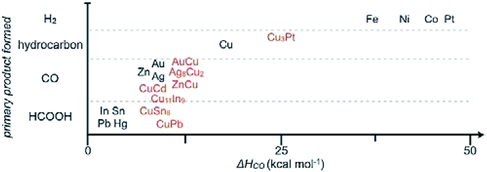
As stated before, we separately summarized the electrode used after fabrication without post-treatment and the powder materials used after assembly or drop casting to form films/electrodes. The following catalysts are Cu–M powder alloys, which sometimes have to be mixed with a Nafion binder and finally cast on a conductive substrate. Based on some groups’ work, C. P. Berlinguette and co-workers171 provided a general relationship between the primary product formed and the metal–CO bonding strength (Fig. 21). The best CO formation catalysts often had a CO heat of adsorption (ΔH) of 10 kcal mol−1. A lower value of ΔH is more favorable for HCOO− formation, whereas a higher value of ΔH favors H2 and hydrocarbon formation. A series of In–M on titanium substrate was prepared and followed the trend FeIn < CoIn < ZnIn < NiIn < CuIn for CO production.
 | ||
| Fig. 21 General relationship between the primary product formed and CO heat of adsorption (ΔH) for pure metal and mixed metal films. Reproduced from ref. 171 with permission from Wiley, 2017. | ||
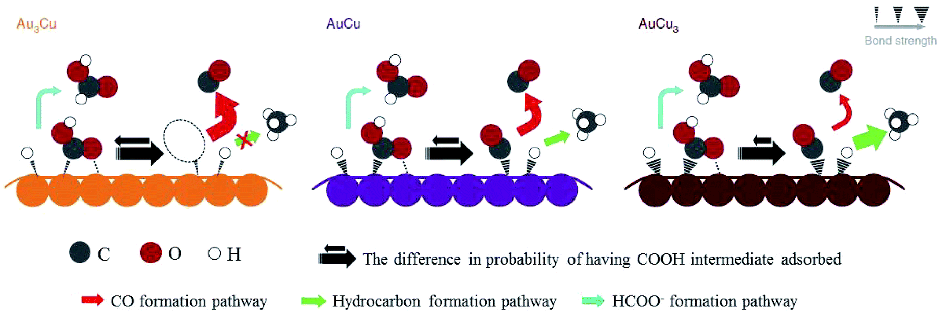
After preparing different ratios of AuxCuy (x = 3, y = 1; x = 1, y = 1; x = 1, y = 3) alloy nanoparticles, P. D. Yang and co-workers172 obtained corresponding monolayer samples on various substrates via self-assembly by the Langmuir–Schaefer method. The monolayer samples showed great mass activity, achieving 67% CO with a partial current of −230 mA mg−1 at −0.73 V vs. RHE for Au3Cu. The activity for CO2 reduction exhibited a volcano shape, where Au3Cu represented the peak, as determined by the electronic and geometric effects (Fig. 22). These effects were associated with the local atomic arrangements at the active sites. In contrast to the AuCu alloys, alloying Pd with Cu could enhance CO and/or C2 products. M. Yamauchi, P. J. A. Kenis and co-workers86 designed CuPd nanoalloys with ordered, disordered, and phase-separated elemental arrangements (Fig. 23). With the same atomic ratio, phase-separated arrangements (more sites with neighbouring Cu atoms) favored the production of C2 products compared to the other two arrangements, with >60% (48% C2H4 and 15% C2H5OH) at −0.7 V vs. RHE. CuPd with ordered arrangements gave 75% CO at −0.7 V vs. RHE. Surface valence bond spectra suggested that geometric effects were key in determining the selectivity compared to electronic effects. N. Umezawa, J. H. Ye and co-workers173 electrodeposited CuPd on glassy carbon and optimized the ratio between Pd and Cu. 80% faradaic efficiency of CO was obtained with optimal Pd7Cu3 at −0.8 V vs. RHE. DFT calculations suggested that synergistic geometric and electronic effects were responsible for the high selectivity. D. Ma, G. X. Wang and co-workers174 loaded CuPd nanoparticles (3.3 nm) on carbon black, and Pd85Cu15/C achieved 86% CO at −0.89 V vs. RHE.
 | ||
| Fig. 22 Proposed mechanism for CO2 reduction on the surface of Au–Cu bimetallic nanoparticles. Larger arrows indicate higher turnover. Reproduced from ref. 172 with permission from Springer Nature, 2014. | ||
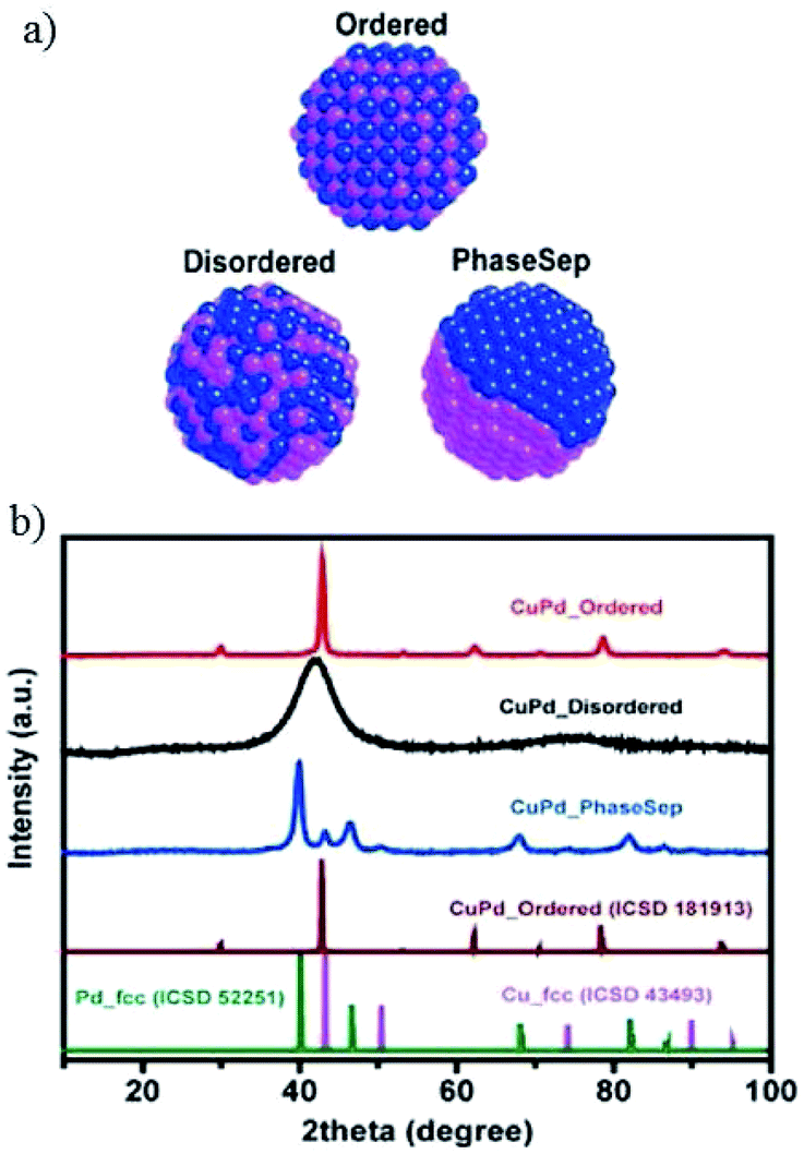 | ||
| Fig. 23 (a) Illustration of prepared CuPd nanoalloys with different atomic mixing patterns: ordered, disordered, and phase separated. (b) XRD patterns of prepared CuPd nanoalloys, as well as previously reported pure Cu, pure Pd and CuPd alloys. Reproduced from ref. 86 with permission from the American Chemical Society, 2017. | ||
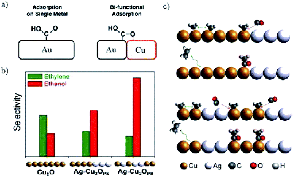 | ||
| Fig. 24 (a) The stabilization of *COOH by introducing bi-functional effects. (b) The selectivity of C2H4 and C2H5OH for Cu2O and Ag-incorporated Cu2O. Experimental conditions: −1.2 V vs. RHE in 0.2 M KCl. (c) The proposed CO-insertion mechanism indicating the transfer of CO from Ag site that weakly binds CO to Cu site that binds residual C1 intermediates in the case of phase separated and phase blended samples in (b). Reproduced from ref. 175 for (a) and ref. 177 for (b) and (c) with permission from the American Chemical Society, 2016 and 2017. | ||
To design Cu–M bimetallic species, therefore, the first aspect to be considered is the group that the parent metals belong to. The preparation method also has an influence on the activity. The most important thing for mechanism investigation in this system is precise control of the composition, morphology and position of the bimetallic species.
4.4 Surface modification of Cu-based electrocatalysts
In recent years, surface modification has also been investigated for Cu-based electrocatalysts, including inorganic and organic outlayer species. Inorganic outlayers could protect the Cu surface and alter the direct contact between the electrolyte and Cu surface. Then the stability and activity could be altered compared to bare Cu-based electrocatalysts. Y. J. Liang, H. L. Wang and co-workers60 decorated Pd atoms on Cu mesh by soaking it in PdCl2 + HCl solution. During CO2 reduction, the foreign Pd atoms induced continuous restructuring of the Cu surface, in turn preventing the deactivation of catalysts by incorporating or desorbing accumulated carbonaceous species (Fig. 25). The deactivation of electrodes caused by the adsorption of carbon or intermediates has been reported by many researchers.24,178,179 According to their reports, the Pd content should be optimized to inhibit the deactivation of the Cu electrode and maintain the CO2 reduction activity, since less Pd is not sufficient to improve catalyst durability, while more Pd will change the product selectivity and lead to more H2 production. The selectivity of CH4 and C2H4 remained above 50% for 4 h continuous electrolysis at −0.96 V vs. RHE (0.5 M KHCO3, 20 sccm). J. P. Ramírez and co-workers180 found that Cu–In nanoalloys evolved to a separated core–shell (Cu–In(OH)3) structure after successive electrochemical cycles. The separated catalysts with an In(OH)3 shell showed high selectivity for CO production, and In(OH)3 modification plays an important role in this enhanced selectivity. Later, they also observed >80% HCOO− at −0.8 V vs. RHE (0.1 M KHCO3) with submicron S-modified Cu.181 J. S. Luo, M. Grätzel and co-workers61 modified the surface of CuO nanowire electrodes with SnO2via atomic layer deposition (ALD) and as high as 97% CO was achieved at −0.7 V vs. RHE (10 sccm CO2). Gas phase absorption measurements confirmed the significantly decreased binding strength of both CO and adsorbed H* after SnO2 modification. However, whether the residual oxides (mainly Sn2+ with some Cu+) were active catalysts remained uncertain.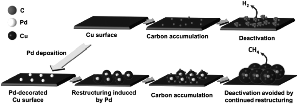 | ||
| Fig. 25 Schematic diagram of Pd-induced surface restructuring that avoids the accumulation of carbonaceous species on the Cu surface. Reproduced from ref. 60 with permission from Wiley, 2017. | ||
Besides modification with inorganic materials, organic ligands are coated on the Cu surface to enhance CO2 reduction, especially for CH4 and C2H4 products through the interactions between key intermediates and the functional groups of ligands. By properly modifying Cu(OH)2 nanowires with amino acid,182 H2 formation could be suppressed and CO2 reduction was promoted since the interaction between the key intermediate CHO* and –NH3+ of the adsorbed zwitterionic glycine stabilized this key intermediate during CO2 reduction. E. Andreoli and co-workers183 modified the Cu foam surface with polyamide and obtained enhanced C2H4 production with unaffected CH4 (0.1 M NaHCO3). They ascribed this enhancement to the charge transfer to the Cu surface, stabilization of the CO dimer by the –NH2 group, and the adsorption of CO near the polymer.
4.5 Supports for Cu-based electrocatalysts
We list all the substrates and/or supports in Table 2, since supports also have an influence on activity. Supports can maintain good dispersion and stabilization of active sites, as well as creating synergistic interactions or active interfaces between supports and copper catalysts. CuO on CO2 capture material exhibited higher C2H4 faradaic efficiency than CuO on carbon black or without support.184 Supports with sufficient surface area were also critical for the high C2–C3 products for densely packed Cu nanoparticles.122 Electrodeposited Cu gave higher activity on graphene oxide and pure graphite than on glassy carbon, which was attributed to the preferential deposition of Cu nanoparticles at defects present on the graphene layers of the former supports.57Generally, Cu foil, Cu plate, Cu mesh, or even FTO is used as a substrate for Cu-based electrocatalysts for EC CO2 reduction, while glassy carbon is used for Cu powder electrocatalysts. Gas diffusion layers (GDL) or gas diffusion electrodes (GDE) were also chosen as substrates to enhance the performance of the corresponding loaded Cu-based electrocatalysts due to their gas/electrolyte penetrability.86,150 Polymer on FTO169 or glassy carbon170 was used as a substrate to enhance the local concentration of CO2. Polymer-based diffusion layers or electrodes have also been fabricated recently to enhance the activity and stability of Cu electrocatalysts, where as high as 76% C2H4 was obtained at −0.55 V vs. RHE.103,185
Therefore, in order to improve the performance of Cu-based electrocatalysts, supports or substrates with high surface area and high gas and liquid penetrability should be considered. More recently, it was found that Cu3N support could act as an underlying stable Cu+ species to reduce the CO dimerization energy barrier.186 This might be another consideration when choosing supports for copper electrocatalysts.
5. Electrolyte effect on CO2 reduction with Cu-based heterogeneous electrocatalysts
In EC CO2 reduction, aqueous electrolytes are generally selected by researchers due to their environmentally friendly properties, low cost and potential for coupling with water oxidation. Non-aqueous electrolytes are also studied by many researchers due to their large electrochemical window, high CO2 solubility and low proton availability.5.1 Aqueous electrolytes
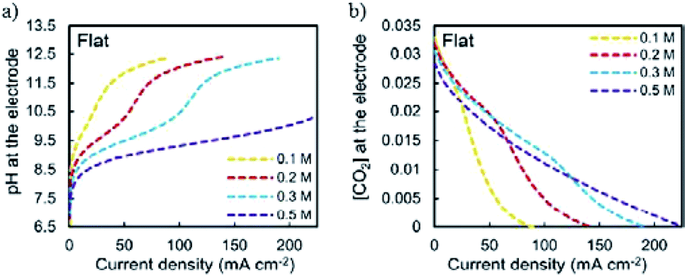
In a pioneering study, Hori and co-workers34 investigated CO2 reduction on Cu sheet electrodes in various electrolytes at 5 mA cm−2. The major product was H2 with FE >70% in KH2PO4/K2HPO4, which decreased to 10% in KClO4. C2H4 and alcohols were favored in KCl, K2SO4, KClO4 and diluted KHCO3 electrolytes, whereas CH4 was favored in concentrated KHCO3 and KH2PO4/K2HPO4.The concentration of bicarbonate and cation size both play important roles during CO2 reduction. A high concentration of bicarbonate leads to a relatively high pH, which in turn favors CH4 formation, while a big cation size promotes C2H4 and other C2 products. G. Mul and co-workers24 investigated the influence of the electrolyte on the selectivity of Cu2O-derived Cu. An increased electrolyte concentration led to a decreased C2H4/CH4 ratio (0.05 M, 0.1 M, 0.2 M KHCO3, 50 sccm CO2). P. Strasser and co-workers25 also observed that a low concentration of bicarbonate electrolyte favored H2 and CH4 formation, while a high concentration of bicarbonate, which showed a high interfacial pH near the Cu surface, favored C2H4 formation (0.05 to 0.2 M KHCO3). For various different concentrations of electrolytes, E. H. Sargent, D. Sinton and co-workers79 predicted the pH and CO2 concentration at the electrode surface using a diffusion-based model (Fig. 26). CO2 limitation occurred under high local pH conditions. In 1991, Hori and co-workers found that cationic species (Li+, Na+, K+ and Cs+) in bicarbonate solution affected the product selectivity (C2H4/CH4).187 A. T. Bell and co-workers188,189 recently also reported that there was a decrease in faradaic efficiency for H2 and CH4, and an increase in faradaic efficiency for C2H4 and C2H5OH for Cu cathodes with increasing cation size (Li+, Na+, K+, Rb+, and Cs+) (Fig. 27a). They ascribed the effect of the electrolyte cation size on CO2 reduction to cation hydrolysis in the vicinity of the cathode. The pKa for hydrolysed cations decreased and they served as buffer agents to lower the local pH, leading to an increase in the local concentration of dissolved CO2 (Fig. 27b and c). The concentration of molecular CO2 decreased with increasing pH due to its rapid consumption by hydroxyl anions to form HCO3− and CO32−. This process occurred at much higher rates than the rate of CO2 reduction. In contrast to CO2 reduction, by using single-crystal Cu(100), single-crystal Cu(111), and polycrystalline Cu electrodes, M. T. Koper, F. C. Vallejo and co-workers190 found that the cation effects were potential- and structure-dependent in CO reduction (Fig. 27d); the onset potential for C2H4 was lower for the single crystals (−0.3 V and −0.4 V vs. RHE for Cu(100) and Cu(111)) than for the polycrystalline electrode, for which the overpotential increased with increasing cation size. The onset potential for CH4 (−0.65 V vs. RHE) was independent of both cation size and surface structure. When the applied potential was more negative than −0.65 V vs. RHE, larger cations enhanced CH4 formation. When the applied potential was from −0.65 V to −0.3 V vs. RHE, larger cations increased C2H4 selectivity.
 | ||
| Fig. 26 (a) Predicted local pH and (b) CO2 concentration at the electrode surface using a diffusion-based model. Reproduced from ref. 79 with permission from the Royal Society of Chemistry, 2017. | ||
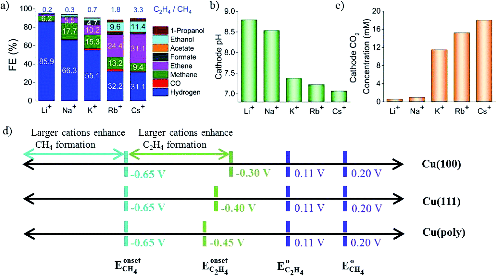 | ||
| Fig. 27 (a) The selectivity of CO2 reduction products in different bicarbonate electrolytes. (b) Calculated local pH. (c) CO2 concentration at the Cu surface. Schematics of structure- and potential-dependent cation effects. Experimental conditions: −1.0 V vs. RHE, 0.1 M LiHCO3, NaHCO3, KHCO3, RbHCO3, and CsHCO3. Reproduced from ref. 188 for (a) to (c) and ref. 190 for (d) with permission from the American Chemical Society, 2016 and 2017. | ||
Halides are sometimes directly added into aqueous electrolytes to enhance the CO2 reduction and suppress the competing H2 evolution. P. Strasser and co-workers191 added various concentrations of halides into KHCO3 electrolytes and observed that the addition of Cl− and Br− resulted in increased CO selectivity. The adsorbed I− exhibited a larger effect on CH4 production than C2H4. The probable reason was the induced negative charge possessed a remarkably positive effect favoring the protonation of CO. KCl was also used as a catholyte because it resulted in a higher local pH and the formation of bi-phasic Cu2O–Cu, favored for multicarbon fuel production.177
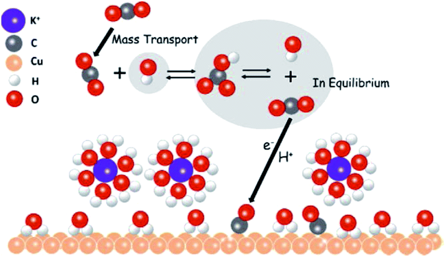
As indicated above, high concentrations, large cation sizes and halide additives could be considered for CO2 reduction in bicarbonate electrolytes in order to obtain more hydrocarbon products. Moreover, regarding the role of bicarbonate aqueous electrolytes, recently M. H. Shao’s group192 directly observed that CO2 molecules were mediated to the Cu surface via their equilibrium with bicarbonate anions rather than direct adsorption from the solution (Fig. 28), using attenuated total reflection surface-enhanced infrared absorption spectroscopy, isotopic labelling, and potential stepping techniques.
 | ||
| Fig. 28 The proposed role of bicarbonate anions in EC CO2 reduction. Reproduced from ref. 192 with permission from the American Chemical Society, 2017. | ||
5.2 Non-aqueous solvents
:3 v/v), which is much higher than that in aqueous solution. However, the current density is only −1.15 mA cm−2. They197 also electrodeposited Cu2O on FTO and achieved almost 90% HCOO− in DMF/H2O (99:1, v/v) at −2.0 V vs. Fc+/Fc with current density −1.5 mA cm−2. Z. C. J. Xu and co-workers199 tuned Cu electrodeposition by the addition of phosphate buffer and obtained 80% HCOO− selectivity at −1.45 V vs. NHE in MeCN (E1/2 of Fc+/Fc couple was 0.40 V vs. NHE in MeCN), with current density −1.35 mA cm−2.
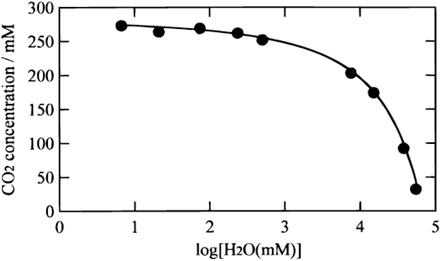 | ||
| Fig. 29 CO2 concentration in a mixture of CH3CN and H2O versus the H2O content. Reproduced from ref. 195 with permission from the Electrochemical Society, 2000. | ||
Therefore, organic solvents and ionic liquids are better choices for suppressing H2 evolution in catalyst systems not suitable for aqueous solutions. In aqueous systems, alkaline conditions could promote C–C coupling during CO2 reduction.207,208 For the ultimate goal of CO2 recycling, neutral aqueous solution is the best choice and various concentrations and cations could be applied to tune the activity.
6. EC/PEC CO2 reduction and H2O oxidation as an overall reaction system for Cu-based electrocatalysts
6.1 EC
The EC CO2 reduction and H2O splitting produces carbon-based fuels and oxygen. Realizing the overall reaction with one catalyst in a single device is desirable. In such a system, the catholyte and anolyte may be different for specific half reactions. T. J. Meyer and co-workers209 combined two half reactions catalyzed by Cu(II)/Cu(0) electrode. As shown in Fig. 30, the electrode for CO2 reduction into CO/HCOO− was Cu(0) film electrodeposited on a boron-doped diamond electrode. A boron-doped diamond electrode immersed in Cu(II) was used for H2O oxidation into O2. This report demonstrates that a simple Cu(II)/Cu(0) electrode is sufficient to catalyze CO2 reduction and H2O splitting in neutral aqueous solution with a H-type cell. However, more aspects should be considered when choosing different catholytes and anolytes, for example the membrane used in the H-type cell. By using SnO2-modified CuO nanowire electrodes as both the cathode for CO2 reduction and the anode for the oxygen evolution reaction, J. S. Luo, M. Grätzel and co-workers61 constructed a complete CO2 electrolysis system with a bipolar membrane. Bipolar membranes consisting of a cation exchange layer and an anion exchange layer were also investigated in other systems for CO2 reduction and H2O oxidation with different catholytes and anolytes. Bipolar membranes needed a lower cell voltage than monopolar membranes.210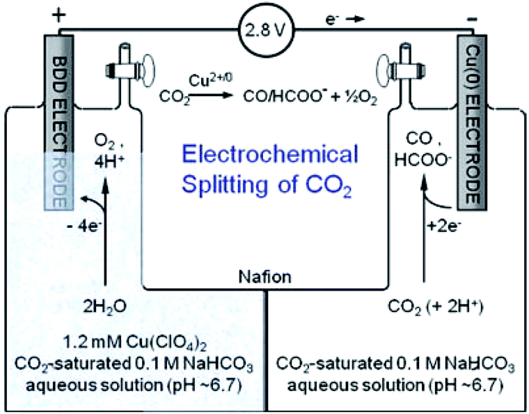 | ||
| Fig. 30 Schematic diagram for overall reaction of CO2 reduction and H2O oxidation using Cu electrode in H-type cell. Reproduced from ref. 209 with permission from the Royal Society of Chemistry, 2013. | ||
6.2 PEC
Solar energy is the largest source of renewable energy. Coupling solar irradiation with EC CO2 reduction is of considerable interest.211,212 In this review, we do not discuss photocatalytic (PC) CO2 reduction with Cu-based materials; readers interested in this topic are directed to some recent reports, including of p-type CuI,213 Cu-decorated TiO2,214 CuO nanoclusters on Nb3O8 nanosheets,215 Au–Cu nanoalloys supported on TiO2,216 carbon-decorated Cu2O mesoporous nanorods,217etc. We will focus on photoelectrochemical (PEC) CO2 reduction with Cu-based catalysts, where similar photoelectrolysis cells as for PEC water splitting are made for PEC CO2 reduction.In a PEC CO2 reduction system, sunlight, visible light and UV light are three options for the light source. For the purpose of solar energy utilization, sunlight irradiation without bias potential is the ultimate goal. Cu2O with a direct band gap of ∼2.0 eV is a promising material for enhancing CO2 activity and inhibiting H2 evolution in PEC CO2 reduction systems. N. R. Tacconi, K. Rajeshwar and co-workers218,219 first reported the utilization of Cu2O for CO2 PEC reduction. They electrodeposited Cu2O nanocrystals on CuO nanorod arrays. 95% CH3OH was formed with a bias potential of +0.17 using this CuO@Cu2O nanorod array as a photocathode (AM 1.5, 70 mW cm−2). Modifying the Cu-based photocathode could lead to different enhanced CO2 reduction products. L. R. Baker and co-workers220 electrodeposited CuFeO2/CuO on FTO and used it as a photocathode. 80% CH3COO− was detected with a bias potential of +0.2 V under white-light LED illumination (100 mW cm−2). P. D. Yang and co-workers221 directly assembled Au3Cu nanoparticles on the surface of TiO2-protected silicon nanowire as a photocathode. Compared with the planar counterpart, lower overpotential or additional bias (∼120 mV lower) was needed to drive CO2 reduction to CO. 80% CO could be achieved at −0.2 V vs. RHE (LED light source with intensity 20 mW cm−2, wavelength λ = 740 nm).
When Cu-based electrocatalysts are used as a cathode, both the cathode and the photoanode could be manipulated to enhance the performance of the overall system. J. S. Lee and co-workers222 constructed a PEC system comprising a WO3 photoanode and Cu cathode for CO2 reduction. 71.6% carbonic products (65% CH4) were obtained at +0.65 V vs. RHE under visible light irradiation (>420 nm). M. Miyauchi, H. Abe and co-workers223 obtained 79% HCOO− when using Cu–Zn alloy film as a cathode in 0.1 M KHCO3 and SrTiO3 as a photoanode in 0.1 M KCl + 0.01 M NaOH under UV light illumination without applied bias potential. Y. S. Kang and co-workers224 engineered a (040) facet BiVO4 photoanode and integrated it with a Cu cathode for CO2 PEC reduction (Cu cathode|NaCl|BiVO4 photoanode). Different products were obtained by tuning the bias potential, such as 65.4% HCOO− (+0.75 V), 85.1% HCHO (+0.9 V), 6.89% CH3OH and 4.4% C2H5OH (+1.35 V) in 0.5 M NaCl (AM 1.5).
When using CuxO as a photocathode or cathode, corrosion will happen. Protective layers such as TiO2 were applied in studies done well by M. Grätzel’s group. J. L. Gong and co-workers225 introduced a simple strategy by using Cu2O as the cathode and TiO2 nanorods as the photoanode for PEC reduction of CO2. 92.6% carbonic products (54% CH4, 30% CO, 3% CH3OH) were obtained at +0.75 V vs. RHE bias potential (AM 1.5, 100 mW cm−2). Through cut-off filter experiments, they confirmed that the photogenerated electrons were not the main reason for Cu2O corrosion; instead, photogenerated holes were primarily responsible for the instability of Cu2O. As shown in Fig. 31, the photogenerated electrons were consumed at the electrode/electrolyte interface, while the holes moved to the back contact and the counter electrode. Back illumination (the travel distance of the electrons was longer than that of the holes) was favorable for the stability of Cu2O.
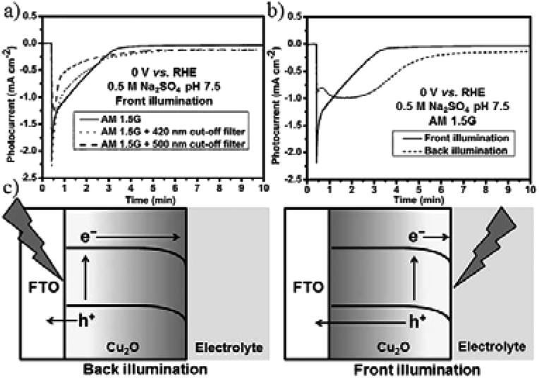 | ||
| Fig. 31 Photocurrent–time curves of Cu2O photocathode under (a) different light sources and (b) front and back illumination. Experimental conditions: 0.5 M N2-saturated Na2SO4, 0 V vs. RHE, 100 mW cm−2. (c) The travel distances of electrons and holes under front and back illumination. Reproduced from ref. 225 with permission from Wiley, 2016. | ||
The photocurrent density is relatively low for the above reported systems, as listed in Table 2. One future aim is to improve the photocurrent density in PEC CO2 conversion. Constructing a hybrid catalyst consisting of a molecular catalyst and semiconductor material for PEC CO2 reduction could improve the selectivity and efficiency.226–228 For a hybrid system, careful design of the semiconductor is also important. As shown in Fig. 32a, M. T. Mayer, M. Grätzel and co-workers229 designed a heterogeneous catalyst system by covalently immobilizing molecular Re(bpy) (CO)3Cl onto a TiO2-protected Cu2O photocathode (Cu2O/AZO/TiO2) via phosphonate linkers. On the TiO2 layer there was also a mesoporous film of 4.5 to 5 μm thickness with 18 nm TiO2 particles. The catalyst system without mesoporous TiO2 did not show substantial photocurrents, while mesoporous TiO2 (enhanced roughness and catalyst loading) exhibited enhanced photocurrents (Fig. 32b). 80–95% CO was achieved under chopped light illumination with photocurrent density of 2.5 mA cm−2 at −1.9 V vs. Fc+/Fc.
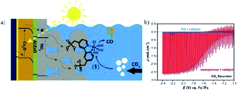 | ||
| Fig. 32 (a) Schematic of hybrid system of protected Cu2O photocathode with covalent-bound Re(bpy) (CO)3Cl. (b) Corresponding PEC performance with and without mesoporous TiO2 layer on the surface of protected Cu2O photocathode. Experimental conditions: CO2-saturated CH3CN (0.1 M Bu4NPF6), scan rate 10 mV s−1, 100 mW cm−2. Reproduced from ref. 229 with permission from the American Chemical Society, 2016. | ||
6.3 PV cells or PV-electrolyzers
The potential bias could be supplied by other forms of energy for PEC electrocatalysis, such as solar PV panels.36,212,230–233 The first idea to apply PV cells for PEC water splitting into hydrogen and oxygen was proposed in 1995 (ref. 234) and has been widely used, whereas its use for the overall reaction of CO2 reduction and H2O oxidation was reported in 2008 (ref. 235) and there are very few examples for the overall reaction system. Recently, J. S. Luo, M. Grätzel and co-workers61 designed a triple-junction GaInP/GaInAs/Ge solar cell driving a CuO@SnO photocathode/photoanode system (Fig. 33a). At a voltage of 2.38 V (AM 1.5, 100 mW cm−2), a solar-to-CO free-energy conversion efficiency peaking at 13.4% with 81% CO selectivity was obtained at −0.55 V vs. RHE (Fig. 33b) and the photocurrent could be up to 12 mA cm−2.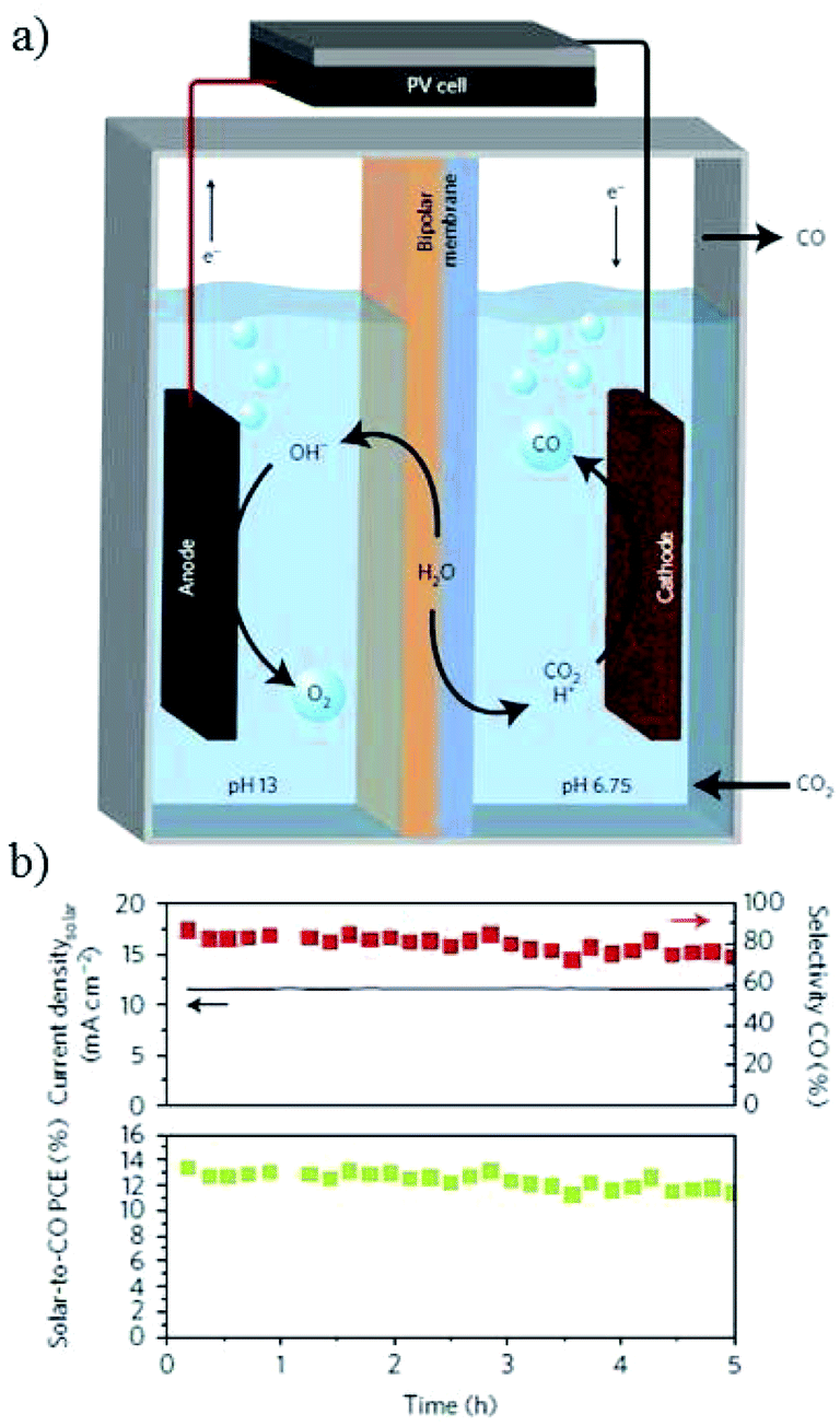 | ||
| Fig. 33 (a) Schematic of PEC CO2 reduction with PV cell. (b) Solar-to-CO conversion efficiency and selectivity of CO versus time. Experimental conditions: 0.1 M CsHCO3‖0.25 M CsOH, −0.55 V vs. RHE, PV cell (0.5625 cm2, 100 mW cm−2, 2.38 V). Reproduced from ref. 61 with permission from Springer Nature, 2017. | ||
The use of other forms of sustainable energy such as solar energy to drive the overall reaction of CO2 reduction and water splitting is promising. CuxO could be used as both a cathode and photocathode after surface protection, as stated above. It is also promising to use Cu oxide species directly as cathodes and photocathodes, since the Schottky junction between Cu2O and Cu could facilitate electron and hole separation, leading to enhanced activity.236 The morphology and activity evolution of CuxO is worthy of further investigation because the chemical changes of CuxO due to photocorrosion and electroreduction processes were indeed pre-activation steps for CO2 reduction, as discussed in this review for oxide-derived Cu.
7. Summary and outlook
As part of the response to the energy crisis and environmental issues, the electrochemical reduction of CO2 has attracted increasing attention from researchers. Until now, Cu-based materials remain the most investigated heterogeneous systems for CO2 electrolysis due to their distinct advantages for hydrocarbon formation. The high abundance and low cost of Cu will further enable it to become a “star” material in the future.In this review, the latest progress on Cu-based heterogeneous electrocatalysts for EC CO2 reduction was discussed. We summarized the benchmark activity for specific products in Section 3 and various types of Cu-based materials reported by different research groups in Section 4. The H2 evolution reaction is inevitable because its equilibrium potential is lower than that of CO2 reduction. Apart from engineering the material, therefore, adjusting the electrolyte composition from aqueous to non-aqueous, adding ionic liquid or other additives, and careful pre-treatment of the system are also important. Through the discussions in this review, we hope we could provide useful information to newcomers to the field through detailed information about the experimental conditions, and to those already experienced in the topic through the comparison data in Table 2 and our focus on the more recent literature about Cu-based heterogeneous electrocatalysts (2013–2019).
| Electrocatalysts | Electrolyte saturated with CO2, flow rate of CO2 gas, and reference electrode used | Faradaic efficiency (FE) and current density for major products, and products distribution | Ref. |
|---|---|---|---|
| All potentials are converted to versus RHE if not specified | |||
| a The potential applied for EC CO2 reduction versus RHE is calculated according to the equation E (vs. RHE) = E0 (vs. Ag/AgCl) + E (vs. Ag/AgCl) + 0.0591pH − η(IRdrop) in aqueous solution. E0 (vs. Ag/AgCl) = 0.21 V, 0.197 V, and 0.21 V for 3 M KCl, saturated KCl, and 3 M NaCl, respectively. | |||
| Morphology | |||
| Cu sheet | 0.1 M KHCO3 | CO and HCOO− as main products (>−0.6 V); hydrocarbons and alcohols are favorably produced (<−0.7 V) | 1989 (ref. 34) |
| 0.1 M KHCO3 | 29% CH4, 30% C2H4, 7% EtOH, 9% HCOO−, 11% H2 (−0.81 V), current density 5.0 mA cm−2 | ||
| 0.1 M KClO4 | 10% CH4, 48% C2H4, 16% EtOH, 9% HCOO−, 7% H2 (−0.89 V), current density 5.0 mA cm−2 | ||
| 0.1 M K2HPO4 | 17% CH4, 5% HCOO−, 72% H2 (−0.64 V), current density 5.0 mA cm−2 | ||
| Cycling-derived Cu nanoparticle (50–100 nm) covered Cu foil | 0.1 M KClO4 (pH = 6.0) | Electropolished (smooth): 14% C2H4 and 5% CH4 (at −1.1 V), LSV onset potential −1.0 V | 2012 (ref. 114) |
| Nanoparticle covered: 36% C2H4 and 1% CH4 (at −1.1 V), LSV onset potential −0.6 V | |||
| Sputtered: 26% C2H4 and 8% CH4 (at −1.1 V), LSV onset potential −0.8 V | |||
| Cu nanoparticles on glassy carbon plate | 0.1 M KHCO3, 30 sccm CO2 | 5–15 nm: 20–25% CO, 60–70% H2, 10–15% CH4, 0–10% C2H4 (−1.1 V), current density −48 mA cm−2 for 2 nm | 2014 (ref. 65) |
| Ag/AgCl | Cu foil: 5% CO, 20% H2, 57% CH4, 20% C2H4 (−1.1 V), current density −23 mA cm−2 | ||
| Cu nanoparticle spin-coated on glassy carbon (7 nm evolved to 23 nm during reaction) | 0.1 M NaHCO3, 20 sccm CO2 | Cu nanoparticle (7–25 nm): 76% CH4 at −1.35 V with partial current density 9.5 mA cm−2, FE onset potential −0.95 V | 2014 (ref. 77) |
| Ag/AgCl | Cu foil: 44% CH4, 35% H2 (−1.35 V) | ||
| Cu nanoparticles (100 nm) on carbon paper by pulse electrodeposition | 0.5 M NaHCO3, 1 sccm CO2 | 85% CH4 at −2.1 V with partial current density 38 mA cm−2, FE onset potential −1.1 V | 2017 (ref. 115) |
| SCE | |||
| Amorphous Cu nanoparticles (3.3 nm) on carbon cloth | 0.1 M KHCO3, 20 sccm CO2 | Amorphous (3.3 nm): 37% HCOOH, 22% C2H5OH (−0.8 V), partial current density 6 mA cm−2, FE onset potential −0.6 V | 2018 (ref. 78) |
| 1 mg/1 × 1 cm2 | Ag/AgCl (saturated KCl) | Crystalline (3.4 nm): 26% HCOOH (−0.8 V), 6% C2H5OH (−1.1 V) | |
| Cu nanoparticles (2–4 nm)/C on glassy carbon plate | 0.1 M KHCO3, 20 sccm CO2 | 57% C2H4 at −1.1 V, current density −17.5 mA cm−2 | 2019 (ref. 121) |
| 0.2 mg/0.5 cm2 | Ag/AgCl (3 M NaCl) | ||
| Branched CuO nanoparticles drop-casted on glass carbon | 0.1 M KHCO3, 60 sccm CO2 | 70% C2H4 at −1.0 V with partial current density −17.0 mA cm−2 | 2019 (ref. 106) |
| 0.2 mg/0.5 cm2 | Ag/AgCl | ||
| Cu nanocubes spin-coated on glassy carbon | 0.1 M KHCO3, 5 sccm CO2 | 63 nm: 63% for carboneous products: 25% C2H4, 11% CH4 | 2016 (ref. 129) |
| 0.2 mg/2.5 × 2.5 cm2 | Ag/AgCl | 44 nm: 80% for carboneous products: 41% C2H4, 20% CH4 | |
| 24 nm: 43% for carboneous products: 9% C2H4, 14% CH4, 15% HCOO− | |||
| At −1.1 V, current density −0.5, −5.5, −7.5 mA/cmECSA2 respectively | |||
| Cu foil: 20% C2H4, 20% CH4, 7% HCOO− (−1.1 V) | |||
| Electrodeposited Cu nanofoam (pore sizes 20–50 μm) | 0.1 M KHCO3 (pH = 6.8) | Major products: HCOOH, H2, and CO | 2014 (ref. 88) |
| Ag/AgCl | Minor products (<2%): C2H4, C2H6, CH4, and C3H6 | ||
| Not quantified (≪1%): CH3OH, C2H5OH | |||
| The onset potential for HCOOH is −0.4 V; with a FE of 26% at −0.5 V; with a maximum FE of 37% at −0.9 V | |||
| The FE for smooth copper electrode is <1% at −0.5 V, 25% at −0.9 V | |||
| Cu mesopore (pore size/depth, 300 nm/40 nm, 30 nm/40 nm, 30 nm/70 nm) | 0.1 M KHCO3 | Cu main products: C1(CO 2% + CH4 46%) 48%, C2(C2H4) 8% at −1.3 V, current density 10 mA cm−2, LSV onset potential −0.56 V | 2016 (ref. 133) |
| Ag/AgCl (3 M KCl) | 300 nm/40 nm: C1(CO 2% + CH4 16%) 18%, C1(HCOOH)32%, C2(C2H4)9% | ||
| 30 nm/40 nm: C1(CO 5% + CH4 14%)19%, C2(C2H4)38% | |||
| 30 nm/70 nm: C1(CO 8% + CH4 6%)14%, C2(C2H4)3%, C2(C2H6)46% | |||
| At −1.3 V, current density 14.3 mA cm−2, LSV onset potential −0.56 V | |||
| Nanoporous CuDAT-wire | 1 M KOH (flow cell) | A maximum of C2H4 40% with partial current density 40 mA cm−2 and C2H5OH 20% with partial current density 15 mA cm−2 at −0.5 V, FE onset potential −0.35 V | 2017 (ref. 87) |
| (DAT-3,5-diamino-1,2,4-triazole, additive during electrodeposition) | Ag/AgCl | ||
| 0.28 mg cm−2 | |||
| 3D porous hollow fibre Cu (hydrogenation of CuO) | 0.3 M KHCO3, 20 sccm CO2 | 72% CO at −0.4 V with partial current density 5.6 mA cm−2, FE onset potential −0.15 V | 2016 (ref. 31) |
| Ag/AgCl (3 M NaCl) | |||
|
|||
| Oxide-derived Cu | |||
| Annealed Cu foil (thick Cu2O)-derived Cu | 0.5 M NaHCO3 (pH = 7.2), 5 sccm CO2 | Cu foil: a maximum of CO 20% at −0.8 V, 33% HCOOH at −0.7 to −0.9 V | 2012 (ref. 69) |
| (≥∼3 μm thickness) | Ag/AgCl (3 M KCl) | Annealed Cu foil: a peak of CO 45% at −0.3 to −0.5 V, 33% HCOOH at −0.45 to −0.65 V, current density 0.5–7 mA cm−2 at −0.3 to −0.65 V | |
| Annealed Cu gauze (CuO nanowire)-derived Cu (size 50–100 nm, length 10–50 μm) | 0.1 M KHCO3 (pH = 6.8), 20 sccm CO2 | Electrochemical reduction: CO + HCOOH 70–80% at −0.3 to −0.5 V; a peak of CO 61.8% at −0.4 V, HCOOH 30.7% at −0.6 V, current density 0.5–10 mA cm−2 at −0.3 V to −0.6 V | 2015 (ref. 80) |
| Ag/AgCl (saturated KCl) | Forming gas reduction: H2 >90% at −0.3 to −0.5 V, FE onset potential for CO2 reduction is −0.6 V | ||
| Annealed Cu(OH)2 foil (CuO nanowire)-derived Cu (length 8.1 μm) | 0.1 M KHCO3 (pH = 6.8) | 8% C3H7OH (FE onset potential −0.9 V), 4% C2H5OH (FE onset potential −0.7 V), 2% C2H6 (FE onset potential −0.7 V), 17% C2H4, 18% HCOOH, 40% H2 at −1.1 V | 2016 (ref. 134) |
| Ag/AgCl (saturated KCl + AgCl) | Cu foil: 3% C2H4, 12% HCOOH, 80% H2 at −1.1 V | ||
| Electrodeposited Cu2O film on Cu plate | 0.1 M KHCO3 (pH = 6.8), 5 sccm CO2 | A maximum of C2H4 33% with partial current density 12 mA cm−2, ratio of C2H4/CH4 8–12 (−1.1 V), FE onset potential −0.8 V | 2014 (ref. 72) |
| Ag/AgCl (3 M NaCl) | |||
| Electrodeposited Cu2O film on GDE | 0.5 M KHCO3 | A maximum of C2H4 26%, ratio of C2H4/CH4 up to 26 (−1.2 V), current density 12.5 mA cm−2 | 2015 (ref. 150) |
| Ag/AgCl | |||
| Electrodeposited Cu2O film (1.7–3.6 μm) on Cu disc | 0.1 M KHCO3, 20 sccm CO2 | A maximum of C2H4 34–39% and C2H5OH 9–16%, ratio of C2H4/CH4 up to 100 (−1.0 V), current density −30 mA cm−2 | 2015 (ref. 81) |
| Ag/AgCl (saturated) | Cu2O-derived (0.9 μm): 40% C2H4, 9% C2H5OH, 8% HCOO− (−1.0 V) | ||
| Cu foil: 9% CO, 14% C2H4, 13% HCOO− (−1.0 V) | |||
| Electrodeposited/oxide-derived Cu nanofoam (pore sizes 50–100 μm) | 0.5 M NaHCO3 (pH = 7.2) | Major products: H2, CO, CH4, C2H4, C2H6, HCOOH | 2016 (ref. 131) |
| Ag/AgCl (3 M KCl) | Not quantified (<1%): CH3OH, C2H5OH | ||
| FE HCOOH <6% at any potentials | |||
| A maximum FE CO of 45% in potentials ranging between −0.6 V and −0.7 V. A maximum of FE C2(C2H4, C2H6) 55% at −0.8 V with partial current density 6 mA cm−2 | |||
| 20% C2H4, 35% C2H6, 15% CO, 6% HCOO−, 15% H2 (−0.8 V) | |||
| 15% C2H4, 8% C2H6, 25% CO, 8% HCOO−, 25% H2 (−0.8 V)–Cu wafer | |||
| Skeleton Cu (annealed, Cu foam electrodeposition) | 0.5 M NaHCO3 (pH = 7.2), 10 sccm CO2 | Electropolished Cu skeleton: at all potentials from −0.6 V to −1.3 V, CO <3% | 2017 (ref. 132) |
| Ag/AgCl (3 M KCl) | Annealed Cu skeleton: CO 15% (−0.6 V), a maximum C2H4 + C2H6 32% (−1.1 V), FE onset for C2 −0.7 V | ||
| Electrodeposited Cu foam on Cu skeleton: CO 19% (−0.6 V), a maximum C2H4 + C2H6 29% (−1.1 V), FE onset for C2 −0.7 V | |||
| Dendritic Cu (electrodeposition, annealed) | 0.5 M KHCO3 (pH = 7.2), 10 sccm CO2 | Electrodeposited dendritic Cu:HCOOH 49% (−0.7 V); C2H4 34% (−1.1 V) |
2017 (ref. 156) |
| Ag/AgCl (3 M KCl) | Annealed dendritic Cu:C2H5OH + C3H7OH 25% (−1.0 V, C2H5OH 13%) with partial current density 2.8 mA/cmECSA2; C3H7OH 13% (−0.9 V) with partial current density 0.9 mA/cmECSA2; FE onset potential −0.8 V |
||
| Galvanostatic cycling in Cu2+-(Cu2O) derived Cu nanocubes on Cu foil | 0.25 M KHCO3, 50 sccm CO2 | 60% C2+(C2H4, C2H5OH, n-C3H7OH) with partial current density 42.5 mA cm−2 at −0.963 V, FE onset for C2 −0.705 V and C3 −0.857 V | 2018 (ref. 59) |
| SCE | |||
| Hydrothermally prepared Cu2O (1.3 and 11.2 μm) on Cu disc | 0.1 M KHCO3, 20 sccm CO2 Ag/AgCl (saturated) | Cu2O derived (1.3 μm): a maximum of C2H4 27% (−1.0 V), C2H6 <3% (−0.5 to −1.1 V) | 2017 (ref. 146) |
| Cu2O derived (11.2 μm): a maximum of C2H4 15% (−0.8 V), C2H6 8% (−0.8 V) with FE onset −0.6 V, current density 20 mA cm−2 | |||
| CuO derived (11.5 μm): a maximum of C2H4 13% (−0.8 V), C2H6 11% (−0.8 V) with FE onset −0.6 V, current density 20 mA cm−2 | |||
| Plasma-treated Cu foil | 0.1 M KHCO3, 30 sccm CO2 | Cu foil: C2H4 30% at −0.9 V, FE onset potential −0.85 V | 2016 (ref. 95) |
| Ag/AgCl | O2 plasma activated Cu:C2H4 60% (−0.9 V, FE onset potential −0.5 V) |
||
| Plasma-treated Cl−-induced Cu2O–Cu nanocube | 0.1 M KHCO3, 20 sccm CO2 | C2 + C3 73% at −1.0 V C2H4 45%, C2H5OH 20%, n-C3H7OH 9%, current density 37 mA cm−2 at −1.0 V | 2017 (ref. 149) |
| Ag/AgCl | |||
| Cl−-induced Cu2O–Cu | 0.1 M KCl (catholyte), 0.1 M KHCO3 (anolyte) | From Cu2O: 46% C2 (22% C2H4 and 24% C2H5OH), 10% C3–C4 (9% C3H7OH, 1% C4H10) at −1.6 V, FE onset for C2 −0.6 V and C3–C4 −1.0 V | 2015 (ref. 160) |
| Ag/AgCl (3 M KCl) | From Cu: 18% C2H4, 6% C2H5OH, 25% CH4 at −1.6 V | ||
| Halide-induced Cu2O–Cu | 0.1 M KHCO3 (pH = 6.8), 5 sccm CO2 | Cycling Cu foil in halide: 16% C2H4, 8% C2H5OH at −1.0 V, current density 12 mA cm−2, FE onset for C2H5OH −0.6 V and C2H4 −0.8 V | 2016 (ref. 142) |
| Ag/AgCl (saturated KCl) | Cu foil: 9%C2H4, 3%C2H5OH at −1.0V | ||
| Cl−-induced Cu218O–Cu on Si (1 μm) | 0.1 M KHCO3, 5 sccm CO2 | Cycling Cu foil in KCl:C2/C3 60% (C2H4 34% with partial current density −7.5 mA cm−2), C1 6.5% at −1.0 V, current density −10.9 mA cm−2 |
2017 (ref. 143) |
| Ag/AgCl | Cu foil: C2/C3 37%, C1 25% at −1.0 V, current density 6.9 mA cm−2 | ||
| Cu2(OH)3Cl-induced Cu2O–Cu nanoneedle on carbon paper (electrodeposited/oxide-derived) | 0.1 M KHCO3, 20 sccm CO2 | 54% C2+(C2H4, CH3COOH, C2H5OH), 18% C1+ (CH4, CO, HCOOH), C2H4/CH4 = 130 at −1.2 V with a C2H4 partial current density 22 mA cm−2, FE onset potential −0.7 V | 2018 (ref. 82) |
| Ag/AgCl (saturated KCl) | Flow cell: C2H4/CH4 = 200 at −1.0 V with a C2H4 partial current density 160 mA cm−2 | ||
|
|||
| Surface modification | |||
| Amino acid-modified Cu(OH)2 nanowire derived Cu (diameter 100–200 nm, length tens of μm) | 0.1 M KHCO3 | Amino acid modified Cu nanowire: 13% C2H4, 21% C2H6, 52H2% (−1.3 V), with partial current density for CxHy 3 mA cm−2 | 2016 (ref. 182) |
| Ag/AgCl (saturated KCl) | Cu nanowire: 6% C2H4, 12% C2H6, 76H2% (−1.3 V) | ||
| Pd atoms-modified Cu mesh | 0.5 M KHCO3, 20 sccm CO2 | Cu: after 4 h, H2(100%) at −0.96 V | 2017 (ref. 60) |
| Ag/AgCl | Pd-decorated Cu: initial and after 4 h, H2 (40%), 50% (CH4 + C2H4) at −0.96 V, current density 50 mA cm−2 | ||
| SnO-modified CuO nanowire | 0.1 M NaHCO3 (pH = 6.75), 10 sccm CO2 | CuO nanowire: 36% CO with a partial current density −0.25 mA cm−2 at −0.7 V | 2017 (ref. 61) |
| Ag/AgCl (saturated KCl) | SnO2-modifed CuO nanowire: 97% CO with a partial current density −1.1 mA cm−2 at −0.7 V | ||
|
|||
| Bimetallic species | |||
| Dendritic Cu–In electrode (dendrite tips of ∼50 nm width) | 0.1 M KHCO3 | Pure dendritic Cu: at all potentials from −0.8 V to −1.1 V, HCOOH <10% | 2017 (ref. 166) |
| Ag/AgCl | Pure In: a maximum of HCOOH 40% at −1.0 V | ||
| Cu–in alloy: At −0.8 and −0.9 V, HCOOH 60% (60 or 80 at% In) | |||
| At −1.0 V, 50% HCOOH and the ratio of H2:CO2 is 2.6:1(40 at% In); a maximum of HCOOH 62% (80 at% In) |
|||
| Cu–In alloy (in situ reduction of annealed/oxide-derived Cu in In solution) | 0.1 M KHCO3, 10 sccm CO2 | Oxide-derived Cu: a maximum of CO (40%) at −0.6 V, current density −1.7 mA cm−2, FE onset potential −0.3 V | 2015 (ref. 73) |
| Ag/AgCl (saturated KCl) | Cu–in alloy: 95% CO at −0.7 V, current density −1.7 mA cm−2, FE onset potential −0.3 V | ||
| Cu–Sn alloy (in situ reduction of oxide-derived Cu in Sn solution) | 0.1 M KHCO3, 10 sccm CO2 | >80% CO at −0.4 to −0.8 V, 90% CO with current density at −0.6 V | 2016 (ref. 74) |
| Ag/AgCl (saturated KCl) | |||
| Electrodeposited CuxZn oxides film | 0.1 M KHCO3, 20 sccm CO2 | A maximum of C2H5OH 29% at −1.05 V with partial current density −8 mA cm−2, FE onset potential −0.95 V | 2016 (ref. 84) |
| Ag/AgCl (saturated) | |||
| AuxCuy alloy nanoparticles assembled on glassy carbon | 0.1 M KHCO3, 30 sccm CO2 | Au: 60% CO with a partial current −180 mA mg−1 at −0.73 V, current density 2.6 mA cm−2 | 2014 (ref. 172) |
| Ag/AgCl (1 M KCl) | Au3Cu: 67% CO with a partial current −230 mA mg−1 at −0.73 V, current density 2.6 mA cm−2 | ||
| AuCu3: 15% CO with a partial current −40 mA mg−1 at −0.73 V, current density 1.4 mA cm−2 | |||
| Cu: 2–3% CO with a partial current −10 mA mg−1 at −0.73 V, current density 0.7 mA cm−2 | |||
| Ag–Cu alloy (Ag–Cu2O derived) | 0.2 M KCl (catholyte)|0.1 M KHCO3 (anolyte) | Phase-separated Ag–Cu2O: 20% C2H5OH at −1.2 V, FE onset potential −1.0 V | 2017 (ref. 177) |
| Ag/AgCl | Phase blended Ag–Cu2O: 34%C2H5OH at −1.2 V, FE onset potential −0.9V | ||
| Pure Cu2O: 11% C2H5OH, FE onset potential −1.0 V | |||
| Electrodeposited Cu–Ag alloy on carbon paper (GDL) with the addition of 3,5-diamino-1,2,4-triazole | 1 M KOH, 7 sccm CO2 | 6% Ag in CuAg alloy: 60% C2H4 with a partial current density −180 mA cm−2 and 25% C2H5OH with a partial current density −90 mA cm−2 at −0.7 V | 2018 (ref. 102) |
| Ag/AgCl | |||
| Electrodeposited Cu–Ag alloy (∼6 nm) on polymer on glassy carbon | 0 °C, 0.5 M KHCO3(8 ppm benzotriazole) | 21% CH3COO− at −1.33 V, FE onset potential −1.1 V | 2018 (ref. 170) |
| SCE | |||
| Electrodeposited Cu–Pd alloy (∼6.6 nm) on polymer on FTO | 0.1 M TBAPF6/CH3CN (1 M H2O), Ag/AgNO3; 0.1 M KHCO3, SCE | Cu2Pd: 51% CH4 at with an overpotential 0.86 V, current density −6.0 mA cm−2 | 2015 (ref. 169) |
| Electrodeposited Cu–Pd alloy on glassy carbon | 0.1 M KHCO3 | Pd7Cu3 80% CO at −0.8 V, current density −1.0 mA cm−2, FE onset potential −0.7 V | 2016 (ref. 173) |
| Ag/AgCl (saturated KCl) | |||
| Cu–Pd alloy nanoparticles on Vulcan carbon coated on carbon paper | 0.1 M KHCO3 | Pd85Cu15, 86% CO with a partial current density −6.9 mA cm−2 at −0.9 V, FE onset potential −0.6 V | 2016 (ref. 174) |
| 2 mg/1 × 2 cm2 | Ag/AgCl | ||
| Cu–Pd alloy nanoparticles on GDE | 0.1 M KOH, 7 sccm CO2, electrolyte flow rate 0.5 sccm at −2 V to −3.5 V and 0.1 sccm at −1.6 V to −2 V vs. Ag/AgCl | Phase-separated CuPd: 48% C2H4, 15% C2H5OH, 15% CO at −0.7 V, FE C2H4 onset −0.4 V, FE C2H5OH onset −0.5 V | 2016 (ref. 86) |
| 4 mg/5.0 × 0.8 cm2 | Disordered CuPd: 12% C2H4, 5% C2H5OH, 50% CO, 4% CH4 at −0.7 V, FE C2H4 onset −0.6 V, FE C2H5OH onset −0.6 V | ||
| Ordered CuPd: 75%CO, 2% CH4 at −0.7 V, FE C2H4 onset −0.7 V, FE C2H5OH onset −0.9 V | |||
| Cu–Pd alloy nanoparticles on Vulcan carbon coated on carbon paper | 0.1 M KHCO3, 10 sccm CO2, | 87% CO at −0.9 V with partial current density 30 mA mg−1 (30 mA cm−2) | 2019 (ref. 241) |
| 1 mg cm−2 | Ag/AgCl (saturated KCl) | ||
|
|||
| Aqueous electrolyte | |||
| Cu foil | 0.1 M MHCO3 (M = Li, Na, K, Rb, Cs, pH = 6.8), 5 sccm CO2 | C2H4/CH4 (Li+0.2, Na+0.3, K+0.7, Rb+1.8, Cs+3.3), H2 (Li+85.9%, Na+66.3%, K+55.1%, Rb+32.2%, Cs+31.1%) | 2016 (ref. 188) |
| Ag/AgCl (saturated KCl) | C2H5OH (Rb+9.6%, Cs+11.4%) | ||
| −1.0 V, current density increased from 2.5 mA cm−2 to 5.5 mA cm−2 with the increase of cation size | |||
| Cu foil | 0.1 M KHCO3, 30 sccm CO2 | 15% CH4, 10% C2H4, 8% CO, 22% HCOO−, 40% H2 (−0.95 V), current density 2.5 mA cm−2 | 2016 (ref. 191) |
| 0.3 M KBr + 0.1 M KHCO3, 30 sccm CO2 | 5% CH4, 7% C2H4, 27% CO, 18% HCOO−, 40% H2 (−0.95 V), current density 2.5 mA cm−2 | ||
| 0.3 M KI + 0.1 M KHCO3, 30 sccm CO2 | 41% CH4, 17% C2H4, 5% CO, 10% HCOO−, 30% H2 (−0.95 V), current density 9.5 mA cm−2 | ||
|
|||
| Non-aqueous electrolyte | |||
| Cu–Cu2O-[Cu(cyclam)](ClO4)2 composite on FTO | 0.1 M n-Bu4BF4 in DMF/H2O (97:3 v/v) |
90% HCOO− at −2.0 V vs. Fc+/Fc, current density −1.15 mA cm−2 | 2015 (ref. 196) |
| Ag/AgCl (3 M KCl) | |||
| Electrodeposited Cu2O on FTO | 0.1 M n-Bu4BF4 in DMF/H2O (99:1 v/v) |
90% HCOO− at −2.0 V vs. Fc+/Fc, current density −1.5 mA cm−2 | 2016 (ref. 197) |
| Ag/AgCl (3 M KCl) | |||
| Cu foil | 0.1 M supporting electrolyte in MeCN | CO, carbonate, bicarbonate as main products | 2016 (ref. 198) |
| Ag/Ag+(0.1 M AgClO4 in MeCN) | |||
| Porous dendritic Cu nanofoam (pore size 30–40 μm, 10 wt% Cu2O) on Cu plate | Ionic liquid [EMIM](BF4)/H2O (98:2 v/v) |
Porous dendritic Cu: 83% HCOO− at −1.55 V vs. Fc+/Fc, current density −5.0 mA cm−2 | 2017 (ref. 206) |
| Ag/AgCl (3 M KCl) | Cu foil: 45% HCOO− at −1.55 V vs. Fc+/Fc | ||
| Phosphate modified dendritic Cu | 0.1 M supporting electrolyte in MeCN | 81% HCOO− at −1.45 V vs. NHE, current density −1.35 mA cm−2 | 2017 (ref. 199) |
| Ag/Ag+ (0.1 M AgNO3 in MeCN) | |||
|
|||
| PEC | |||
| Cu2O nanocrystal/CuO nanorod (photocathode)‖Pt (anode) | 0.1 M Na2SO4, simulated AM 1.5 illumination (70 mW cm−2) | 95% CH3OH, +0.17 V bias potential, photocurrent density 0.2 mA cm−2 | 2013 (ref. 218) |
| Cu2O/AZO/TiO2 (photocathode)‖Pt (anode) | MeCN, 0.1 M Bu4NPF6, under filtered 450 W Xe arc lamp (1 sun) | 80–95% CO at −1.9 V vs. Fc+/Fc, photocurrent density 2.5 mA cm−2 | 2016 (ref. 229) |
| Ag/AgCl wire | |||
| CuFeO2/CuO (photocathode)‖Pt (anode) | 0.1 M NaHCO3 + KPi, white-light LED illumination (100 mW cm−2) | 80% CH3COO−, +0.2 V bias potential, photocurrent density 0.15 mA cm−2 | 2017 (ref. 220) |
| Cu (cathode)‖WO3 (photoanode) | 0.5 M KHCO3(pH = 7.5), visible light (>420 nm) using a 500 W Hg lamp | 71.6% carbonic product (65% CH4), +0.65 V bias potential, photocurrent density 0.25 mA cm−2 | 2014 (ref. 222) |
| Cu2O (cathode)‖TiO2 (photoanode) | 0.1 M KHCO3(pH = 6.9), AM 1.5G illumination (100 mW cm−2) | 92.6% carbonic products (54% CH4, 30% CO, 3% CH3OH), +0.75 V bias potential, photocurrent density 1.34 mA cm−2 | 2016 (ref. 225) |
| Cu–Zn alloy (cathode)‖SrTiO3(photoanode) | 0.1 M KHCO3 (pH = 6.8), 0.1 M KCl + 0.01 M NaOH (anolyte), UV light Hg–Xe lamp (240–300 nm) | 79% HCOO− without bias potential | 2017 (ref. 223) |
| Cu (cathode)‖BiVO4 (photoanode) | 0.5 M NaCl, 300 W Xe arc lamp with AM 1.5G filter (100 mW cm−2) | 65.4% HCOO− at 0.75 V bias potential, photocurrent density 0.1 mA cm2; 85.1% HCHO at 0.9 V bias potential, photocurrent density 0.35 mA cm−2; 6.89% CH3OH and 4.4% C2H5OH at 1.35 V bias potential, photocurrent density 0.75 mA cm−2 | 2018 (ref. 224) |
| PV cell (GaInP/GaInAs/Ge)-CuO@SnO2 (cathode and anode) | 0.1 M CsHCO3 (pH = 6.75, catholyte)‖0.25 M CsOH (pH = 13.3, anolyte), AM 1.5G illumination (100 mW cm−2) and a voltage of 2.38 V | 13.4% solar to CO efficiency at +0.55 V, photocurrent density 12 mA cm−2 | 2017 (ref. 61) |
In summary, the design of efficient and selective Cu-based electrocatalysts is inspiring but still challenging. Several considerations may also be helpful for engineering efficient systems:
(1) PEC CO2 reduction with Cu-based materials. Here, we could manipulate two aspects, one of which is energy supply, such as solar energy and other forms of renewable and clean energy for lower applied overpotentials. Optimization of this technique may develop commercially feasible CO2 reduction systems. Another aspect to consider is the Cu (photo)cathode. The photoanode corrosion of copper oxide species is known by many researchers and studies have been done to prolong its stability under irradiation. However, the instability should not be considered a disadvantage when using the copper oxide species as (photo)cathodes for CO2 reduction. This is because oxide-derived Cu exhibited better performance than its parent counterpart. Moreover, Cu nanostructures possess localized surface plasmonic (LSPR) effects, which have been used for photocatalytic organic synthesis.237,238 To the best of our knowledge, there is no report yet for CO2 reduction utilizing Cu LSPR effects. Future efforts should be made towards this.
(2) Complete systems coupling the reduction of CO2 and H2O oxidation, as well as other significant oxidation reactions. Studying only the half reaction (CO2 reduction) is not sufficient to achieve a commercially feasible CO2 reduction system. The performance of anodic reactions also needs to be investigated. It is necessary to explore Cu-based materials as both cathodes and anodes.
(3) Hybrid system of Cu-based materials and metal complexes. Metal molecular catalysts or metal complexes could coordinate CO2/intermediates with the metal center and ligands. Covalent-attached metal complexes on Cu-based materials will combine the key features of Cu-based materials and allow molecular-level tunability. This may also address the large overpotential required for the Cu electrode and the instability issue of the molecular catalyst.
(4) 3D Cu porous networks. The pore length and pore size of 3D Cu porous structures will influence the diffusion of reactants and intermediates. Tailoring the pore length as well as the pore size from the macropore to mesopore, micropore, and nanopore region will tune the diffusion and, in turn, the performance of the catalyst. In addition, through designing abundant active sites in this porous network to prolong the retention time of specific intermediates, we could expect high selectivity for specific products.
(5) Cu nanoclusters. Although the size effects of Cu nanoparticles have been discussed widely, ultrasmall, atomically precisely controlled Cu nanoclusters are rarely reported. Similar to Au and Ag nanoclusters,239 investigating the reaction mechanism to get a fundamental understanding via the atomic precise control of Cu nanoclusters is critical to design highly efficient and stable Cu nanocluster electrocatalysts.
(6) Design of the flow cell. The fabrication of an efficient flow cell with a designed gas diffusion electrode (GDE) could dramatically promote the activity and stability of CO2 electrocatalysts. More and more attention has been paid to this area over the past two years,103,110,185,208,240 and future efforts could be also made towards this aspect.
Conflicts of interest
There are no conflicts to declare.Acknowledgements
Financial support of this work by the National Science Foundation of China (NSFC, 21703154) and the Natural Science Foundation of Tianjin (18JCYBJC43100) is gratefully acknowledged. X. K. thanks the EPSRC (EP/S025537/1) for financial support.Notes and references
- Z. W. Seh, J. Kibsgaard, C. F. Dickens, I. Chorkendorff, J. K. Norskov and T. F. Jaramillo, Science, 2017, 355 Search PubMed.
- E. V. Kondratenko, G. Mul, J. Baltrusaitis, G. O. Larrazábal and J. Pérez-Ramírez, Energy Environ. Sci., 2013, 6, 3112–3135 RSC.
- R. J. Lim, M. Xie, M. A. Sk, J.-M. Lee, A. Fisher, X. Wang and K. H. Lim, Catal. Today, 2013 Search PubMed.
- A. M. Appel, J. E. Bercaw, A. B. Bocarsly, H. Dobbek, D. L. Dubois, M. Dupuis, J. G. Ferry, E. Fujita, R. Hille, P. J. Kenis, C. A. Kerfeld, R. H. Morris, C. H. Peden, A. R. Portis, S. W. Ragsdale, T. B. Rauchfuss, J. N. Reek, L. C. Seefeldt, R. K. Thauer and G. L. Waldrop, Chem. Rev., 2013, 113, 6621–6658 CrossRef CAS PubMed.
- Q. W. Song, Z. H. Zhou and L. N. He, Green Chem., 2017, 19, 3707–3728 RSC.
- F. Studt, I. Sharafutdinov, F. Abild-Pedersen, C. F. Elkjær, J. S. Hummelshøj, S. Dahl, I. Chorkendorff and J. K. Nørskov, Nat. Chem., 2014, 6, 320–324 CrossRef CAS PubMed.
- S. Kattel, P. Liu and J. G. Chen, J. Am. Chem. Soc., 2017, 139, 9739–9754 CrossRef CAS PubMed.
- M. Bersani, K. Gupta, A. K. Mishra, R. Lanza, S. F. R. Taylor, H. U. Islam, N. Hollingsworth, C. Hardacre, N. H. de Leeuw and J. A. Darr, ACS Catal., 2016, 6, 5823–5833 CrossRef CAS.
- B. Rungtaweevoranit, J. Baek, J. R. Araujo, B. S. Archanjo, K. M. Choi, O. M. Yaghi and G. A. Somorjai, Nano Lett., 2016, 16, 7645–7649 CrossRef CAS PubMed.
- B. Yang, C. Liu, A. Halder, E. C. Tyo, A. B. F. Martinson, S. Seifert, P. Zapol, L. A. Curtiss and S. Vajda, J. Phys. Chem. C, 2017, 121, 10406–10412 CrossRef CAS.
- K. Kobl, S. Thomas, Y. Zimmermann, K. Parkhomenko and A. C. Roger, Catal. Today, 2016, 270, 31–42 CrossRef CAS.
- W. Tu, Y. Zhou and Z. Zou, Adv. Mater., 2014, 26, 4607–4626 CrossRef CAS PubMed.
- S. C. Roy, O. K. Varghese, M. Paulose and C. A. Grimes, ACS Nano, 2010, 4, 1259–1278 CrossRef CAS PubMed.
- J. Ran, M. Jaroniec and S. Z. Qiao, Adv. Mater., 2018, 30, 1704649 CrossRef PubMed.
- D. Gao, F. Cai, G. Wang and X. Bao, Curr. Opin. Green Sustain. Chem., 2017, 3, 39–44 CrossRef.
- B. Khezri, A. C. Fisher and M. Pumera, J. Mater. Chem. A, 2017, 5, 8230–8246 RSC.
- Q. Lu, J. Rosen and F. Jiao, ChemCatChem, 2015, 7, 38–47 CrossRef CAS.
- T. Ma, Q. Fan, H. Tao, Z. Han, M. Jia, Y. Gao, W. Ma and Z. Sun, Nanotechnology, 2017, 28, 472001 CrossRef PubMed.
- L. Shi, G. H. Yang, K. Tao, Y. Yoneyama, Y. S. Tan and N. Tsubaki, Acc. Chem. Res., 2013, 46, 1838–1847 CrossRef CAS PubMed.
- L. Wang, Y. Yi, C. Wu, H. Guo and X. Tu, Angew. Chem., Int. Ed., 2017, 56, 13679–13683 CrossRef CAS PubMed.
- Z. L. Wang, C. Li and Y. Yamauchi, Nano Today, 2016, 11, 373–391 CrossRef CAS.
- W. Zhang, Y. Hu, L. Ma, G. Zhu, Y. Wang, X. Xue, R. Chen, S. Yang and Z. Jin, Adv. Sci., 2018, 5, 1700275 CrossRef PubMed.
- J. Qiao, Y. Liu, F. Hong and J. Zhang, Chem. Soc. Rev., 2014, 43, 631–675 RSC.
- R. Kas, R. Kortlever, H. Yılmaz, M. T. M. Koper and G. Mul, ChemElectroChem, 2015, 2, 354–358 CrossRef CAS.
- A. S. Varela, M. Kroschel, T. Reier and P. Strasser, Catal. Today, 2016, 260, 8–13 CrossRef CAS.
- K. J. P. Schouten, E. Pérez Gallent and M. T. M. Koper, J. Electroanal. Chem., 2014, 716, 53–57 CrossRef CAS.
- A. Wuttig, C. Liu, Q. Peng, M. Yaguchi, C. H. Hendon, K. Motobayashi, S. Ye, M. Osawa and Y. Surendranath, ACS Cent. Sci., 2016, 2, 522–528 CrossRef CAS PubMed.
- M. R. Singh, E. L. Clark and A. T. Bell, Phys. Chem. Chem. Phys., 2015, 17, 18924–18936 RSC.
- D. Ren, J. Fong and B. S. Yeo, Nat. Commun., 2018, 9, 925 CrossRef PubMed.
- K. Hara, A. Tsuneto, A. Kudo and T. Sakata, J. Electrochem. Soc., 1994, 141, 2097–2103 CrossRef CAS.
- R. Kas, K. K. Hummadi, R. Kortlever, P. de Wit, A. Milbrat, M. W. Luiten-Olieman, N. E. Benes, M. T. Koper and G. Mul, Nat. Commun., 2016, 7, 10748 CrossRef CAS PubMed.
- D. W. DeWulf, T. Jin and A. J. Bard, J. Electrochem. Soc., 1989, 136, 1686–1691 CrossRef CAS.
- S. T. Ahn, I. Abu-Baker and G. T. R. Palmore, Catal. Today, 2017, 288, 24–29 CrossRef CAS.
- Y. Hori, A. Murata and R. Takahashi, J. Chem. Soc., Faraday Trans. 1, 1989, 85, 2309–2326 RSC.
- Y. Hori, H. Wakebe, T. Tsukamoto and O. Koga, Electrochim. Acta, 1994, 39, 1833–1839 CrossRef CAS.
- R. Daiyan, X. Lu, Y. H. Ng and R. Amal, ChemSusChem, 2017, 10, 4342–4358 CrossRef CAS PubMed.
- M. Gattrell, N. Gupta and A. Co, J. Electroanal. Chem., 2006, 594, 1–19 CrossRef CAS.
- S. Lee and J. Lee, ChemSusChem, 2016, 9, 333–344 CrossRef CAS PubMed.
- M. R. Dubois and D. L. Dubois, Acc. Chem. Res., 2009, 42, 1974–1982 CrossRef PubMed.
- A. J. Morris, G. J. Meyer and E. Fujita, Acc. Chem. Res., 2009, 42, 1983–1994 CrossRef CAS PubMed.
- J. M. Savéant, Chem. Rev., 2008, 108, 2348–2378 CrossRef PubMed.
- C. Costentin, M. Robert and J. M. Savéant, Chem. Soc. Rev., 2013, 42, 2423–2436 RSC.
- P. Kang, Z. Chen, M. Brookhart and T. J. Meyer, Top. Catal., 2015, 58, 30–45 CrossRef CAS.
- R. Angamuthu, P. Byers, M. Lutz, A. L. Spek and E. Bouwman, Science, 2010, 327, 313–315 CrossRef CAS PubMed.
- Z. Weng, J. Jiang, Y. Wu, Z. Wu, X. Guo, K. L. Materna, W. Liu, V. S. Batista, G. W. Brudvig and H. Wang, J. Am. Chem. Soc., 2016, 138, 8076–8079 CrossRef CAS PubMed.
- Z. Weng, Y. Wu, M. Wang, J. Jiang, K. Yang, S. Huo, X. F. Wang, Q. Ma, G. W. Brudvig, V. S. Batista, Y. Liang, Z. Feng and H. Wang, Nat. Commun., 2018, 9, 415 CrossRef PubMed.
- A. Hicken, A. J. P. White and M. R. Crimmin, Angew. Chem., Int. Ed., 2017, 56, 15127–15130 CrossRef CAS PubMed.
- C. M. Zall, J. C. Linehan and A. M. Appel, J. Am. Chem. Soc., 2016, 138, 9968–9977 CrossRef CAS PubMed.
- Q. Tang, Y. Lee, D. Y. Li, W. Choi, C. W. Liu, D. Lee and D. E. Jiang, J. Am. Chem. Soc., 2017, 139, 9728–9736 CrossRef CAS.
- T. Ikuno, J. Zheng, A. Vjunov, M. Sanchez-Sanchez, M. A. Ortuno, D. R. Pahls, J. L. Fulton, D. M. Camaioni, Z. Li, D. Ray, B. L. Mehdi, N. D. Browning, O. K. Farha, J. T. Hupp, C. J. Cramer, L. Gagliardi and J. A. Lercher, J. Am. Chem. Soc., 2017, 139, 10294–10301 CrossRef CAS.
- J. Albo, D. Vallejo, G. Beobide, O. Castillo, P. CastaÇo and A. Irabien, ChemSusChem, 2017, 10, 1100–1109 CrossRef CAS PubMed.
- H. Xie, J. Wang, K. Ithisuphalap, G. Wu and Q. Li, J. Energy Chem., 2017, 26, 1039–1049 CrossRef.
- H. Xie, T. Y. Wang, J. S. Liang, Q. Li and S. H. Sun, Nano Today, 2018, 21, 41–54 CrossRef CAS.
- C. W. Lee, K. D. Yang, D. H. Nam, J. H. Jang, N. H. Cho, S. W. Im and K. T. Nam, Adv. Mater., 2018, 30, 1704717 CrossRef PubMed.
- S. Nitopi, E. Bertheussen, S. B. Scott, X. Liu, A. K. Engstfeld, S. Horch, B. Seger, I. E. L. Stephens, K. Chan, C. Hahn, J. K. Nørskov, T. F. Jaramillo and I. Chorkendorff, Chem. Rev., 2019, 119, 7610–7672 CrossRef CAS PubMed.
- Y. Hori, H. Konishi, T. Futamura, A. Murata, O. Koga, H. Sakurai and K. Oguma, Electrochim. Acta, 2005, 50, 5354–5369 CrossRef CAS.
- Y. Lum, Y. Kwon, P. Lobaccaro, L. Chen, E. L. Clark, A. T. Bell and J. W. Ager, ACS Catal., 2016, 6, 202–209 CrossRef CAS.
- J. T. Billy and A. C. Co, ACS Catal., 2017, 7, 8467–8479 CrossRef CAS.
- K. Jiang, R. B. Sandberg, A. J. Akey, X. Liu, D. C. Bell, J. K. Nørskov, K. Chan and H. Wang, Nat. Catal., 2018, 1, 111–119 CrossRef CAS.
- Z. Weng, X. Zhang, Y. Wu, S. Huo, J. Jiang, W. Liu, G. He, Y. Liang and H. Wang, Angew. Chem., Int. Ed., 2017, 56, 13135–13139 CrossRef CAS PubMed.
- M. Schreier, F. Héroguel, L. Steier, S. Ahmad, J. S. Luterbacher, M. T. Mayer, J. Luo and M. Grätzel, Nat. Energy, 2017, 2, 17087 CrossRef CAS.
- A. Wuttig and Y. Surendranath, ACS Catal., 2015, 5, 4479–4484 CrossRef CAS.
- E. L. Clark, C. Hahn, T. F. Jaramillo and A. T. Bell, J. Am. Chem. Soc., 2017, 139, 15848–15857 CrossRef CAS PubMed.
- Y. Lum, B. Yue, P. Lobaccaro, A. T. Bell and J. W. Ager, J. Phys. Chem. C, 2017, 121, 14191–14203 CrossRef CAS.
- R. Reske, H. Mistry, F. Behafarid, B. Roldan Cuenya and P. Strasser, J. Am. Chem. Soc., 2014, 136, 6978–6986 CrossRef CAS PubMed.
- K. J. Schouten, Z. Qin, E. Perez Gallent and M. T. Koper, J. Am. Chem. Soc., 2012, 134, 9864–9867 CrossRef CAS PubMed.
- J. He, K. E. Dettelbach, A. Huang and C. P. Berlinguette, Angew. Chem., Int. Ed., 2017, 56, 16579–16582 CrossRef CAS.
- C. W. Li, J. Ciston and M. W. Kanan, Nature, 2014, 508, 504–507 CrossRef CAS PubMed.
- C. W. Li and M. W. Kanan, J. Am. Chem. Soc., 2012, 134, 7231–7234 CrossRef CAS PubMed.
- A. Verdaguer-Casadevall, C. W. Li, T. P. Johansson, S. B. Scott, J. T. McKeown, M. Kumar, I. E. Stephens, M. W. Kanan and I. Chorkendorff, J. Am. Chem. Soc., 2015, 137, 9808–9811 CrossRef CAS PubMed.
- X. Feng, K. Jiang, S. Fan and M. W. Kanan, ACS Cent. Sci., 2016, 2, 169–174 CrossRef CAS PubMed.
- R. Kas, R. Kortlever, A. Milbrat, M. T. Koper, G. Mul and J. Baltrusaitis, Phys. Chem. Chem. Phys., 2014, 16, 12194–12201 RSC.
- S. Rasul, D. H. Anjum, A. Jedidi, Y. Minenkov, L. Cavallo and K. Takanabe, Angew. Chem., Int. Ed., 2015, 54, 2146–2150 CrossRef CAS PubMed.
- S. Sarfraz, A. T. Garcia-Esparza, A. Jedidi, L. Cavallo and K. Takanabe, ACS Catal., 2016, 6, 2842–2851 CrossRef CAS.
- A. Jedidi, S. Rasul, D. Masih, L. Cavallo and K. Takanabe, J. Mater. Chem. A, 2015, 3, 19085–19092 RSC.
- J. Choi, M. J. Kim, S. H. Ahn, I. Choi, J. H. Jang, Y. S. Ham, J. J. Kim and S.-K. Kim, Chem. Eng. J., 2016, 299, 37–44 CrossRef CAS.
- K. Manthiram, B. J. Beberwyck and A. P. Alivisatos, J. Am. Chem. Soc., 2014, 136, 13319–13325 CrossRef CAS PubMed.
- Y. X. Duan, F. L. Meng, K. H. Liu, S. S. Yi, S. J. Li, J. M. Yan and Q. Jiang, Adv. Mater., 2018, 30, 1706194 CrossRef PubMed.
- Y. Pang, T. Burdyny, C. T. Dinh, M. G. Kibria, J. Z. Fan, M. Liu, E. H. Sargent and D. Sinton, Green Chem., 2017, 19, 4023–4030 RSC.
- D. Raciti, K. J. Livi and C. Wang, Nano Lett., 2015, 15, 6829–6835 CrossRef CAS PubMed.
- D. Ren, Y. Deng, A. D. Handoko, C. S. Chen, S. Malkhandi and B. S. Yeo, ACS Catal., 2015, 5, 2814–2821 CrossRef CAS.
- P. De Luna, R. Quintero-Bermudez, C.-T. Dinh, M. B. Ross, O. S. Bushuyev, P. Todorović, T. Regier, S. O. Kelley, P. Yang and E. H. Sargent, Nat. Catal., 2018, 1, 103–110 CrossRef CAS.
- B. Kumar, J. P. Brian, V. Atla, S. Kumari, K. A. Bertram, R. T. White and J. M. Spurgeon, ACS Catal., 2016, 6, 4739–4745 CrossRef CAS.
- D. Ren, B. S.-H. Ang and B. S. Yeo, ACS Catal., 2016, 6, 8239–8247 CrossRef CAS.
- C. Reller, R. Krause, E. Volkova, B. Schmid, S. Neubauer, A. Rucki, M. Schuster and G. Schmid, Adv. Energy Mater., 2017, 7, 1602114 CrossRef.
- S. Ma, M. Sadakiyo, M. Heima, R. Luo, R. T. Haasch, J. I. Gold, M. Yamauchi and P. J. Kenis, J. Am. Chem. Soc., 2017, 139, 47–50 CrossRef CAS PubMed.
- T. T. H. Hoang, S. Ma, J. I. Gold, P. J. A. Kenis and A. A. Gewirth, ACS Catal., 2017, 7, 3313–3321 CrossRef CAS.
- S. Sen, D. Liu and G. T. R. Palmore, ACS Catal., 2014, 4, 3091–3095 CrossRef CAS.
- M. B. Ross, C. T. Dinh, Y. Li, D. Kim, P. De Luna, E. H. Sargent and P. Yang, J. Am. Chem. Soc., 2017, 139, 9359–9363 CrossRef CAS PubMed.
- C. F. C. Lim, D. A. Harrington and A. T. Marshall, Electrochim. Acta, 2017, 238, 56–63 CrossRef CAS.
- D. M. Weekes, D. A. Salvatore, A. Reyes, A. Huang and C. P. Berlinguette, Acc. Chem. Res., 2018, 51, 910–918 CrossRef CAS PubMed.
- J. Hong, W. Zhang, J. Ren and R. Xu, Anal. Methods, 2013, 5, 1086 RSC.
- K. P. Kuhl, E. R. Cave, D. N. Abram and T. F. Jaramillo, Energy Environ. Sci., 2012, 5, 7050–7059 RSC.
- K. J. P. Schouten, Y. Kwon, C. J. Ham, Z. Qin and M. T. M. Koper, Chem. Sci., 2011, 2, 1902–1909 RSC.
- H. Mistry, A. S. Varela, C. S. Bonifacio, I. Zegkinoglou, I. Sinev, Y. W. Choi, K. Kisslinger, E. A. Stach, J. C. Yang, P. Strasser and B. R. Cuenya, Nat. Commun., 2016, 7, 12123 CrossRef PubMed.
- M. Favaro, H. Xiao, T. Cheng, W. A. Goddard III, J. Yano and E. J. Crumlin, Proc. Natl. Acad. Sci. U. S. A., 2017, 114, 6706–6711 CAS.
- Y. Lum and J. W. Ager, Nat. Catal., 2019, 2, 86–93 CrossRef CAS.
- I. V. Chernyshova, P. Somasundaran and S. Ponnurangam, Proc. Natl. Acad. Sci. U. S. A., 2018, 115, E9261–E9270 CrossRef CAS PubMed.
- L. Dai, Q. Qin, P. Wang, X. Zhao, C. Hu, P. Liu, R. Qin, M. Chen, D. Ou, C. Xu, S. Mo, B. Wu, G. Fu, P. Zhang and N. Zheng, Sci. Adv., 2017, 3, e1701069 CrossRef PubMed.
- J. Jiao, R. Lin, S. Liu, W. C. Cheong, C. Zhang, Z. Chen, Y. Pan, J. Tang, K. Wu, S. F. Hung, H. M. Chen, L. Zheng, Q. Lu, X. Yang, B. Xu, H. Xiao, J. Li, D. Wang, Q. Peng, C. Chen and Y. Li, Nat. Chem., 2019, 11, 222–228 CrossRef CAS PubMed.
- E. Bertheussen, A. Verdaguer-Casadevall, D. Ravasio, J. H. Montoya, D. B. Trimarco, C. Roy, S. Meier, J. Wendland, J. K. Nørskov, I. E. L. Stephens and I. Chorkendorff, Angew. Chem., Int. Ed., 2016, 55, 1450–1454 CrossRef CAS PubMed.
- T. T. H. Hoang, S. Verma, S. Ma, T. T. Fister, J. Timoshenko, A. I. Frenkel, P. J. A. Kenis and A. A. Gewirth, J. Am. Chem. Soc., 2018, 140, 5791–5797 CrossRef CAS.
- T. Burdyny, C. T. Dinh, M. G. Kibria, A. Seifitokaldani, F. P. G. Arquer, C. M. Gabardo, A. Kiani, P. D. Luna, J. P. Edwards, O. S. Bushuyev, C. Q. Zou, Y. J. Pang, R. Q. Bermudez, D. Sinton and E. H. Sargent, Science, 2018, 360, 783–787 CrossRef.
- Q. Zhu, X. Sun, D. Yang, J. Ma, X. Kang, L. Zheng, L. Zhang, Z. Wu and B. Han, Nat. Commun., 2019, 10, 3851 CrossRef PubMed.
- W. Luc, X. Fu, J. Shi, J. J. Lv, M. Jouny, B. H. Ko, Y. Xu, Q. Tu, X. Hu, J. Wu, Q. Yue, Y. Liu, F. Jiao and Y. Kang, Nat. Catal., 2019, 2, 423–430 CrossRef CAS.
- J. Kim, W. Choi, J. W. Park, C. Kim, M. Kim and H. Song, J. Am. Chem. Soc., 2019, 141, 6986–6994 CrossRef CAS PubMed.
- Y. Hori, I. Takahashi, O. Koga and N. Hoshi, J. Phys. Chem. B, 2002, 106, 15–17 CrossRef CAS.
- S. Lee, D. Kim and J. Lee, Angew. Chem., Int. Ed., 2015, 54, 14701–14705 CrossRef CAS PubMed.
- T. T. Zhuang, Y. Pang, Z. Q. Liang, Z. Wang, Y. Li, C. S. Tan, J. Li, C. T. Dinh, P. D. Luna, P. L. Hsieh, T. Burdyny, H. H. Li, M. Liu, Y. Wang, F. Li, A. Proppe, A. Johnston, D. H. Nam, Z. Y. Wu, Y. R. Zheng, A. H. Ip, H. Tan, L. J. Chen, S. H. Yu, S. O. Kelley, D. Sinton and E. H. Sargent, Nat. Catal., 2018, 1, 946–951 CrossRef CAS.
- Y. Zheng, A. Vasileff, X. Zhou, Y. Jiao, M. Jaroniec and S. Z. Qiao, J. Am. Chem. Soc., 2019, 141, 7646–7659 CrossRef CAS PubMed.
- M. B. Ross, P. De Luna, Y. Li, C.-T. Dinh, D. Kim, P. Yang and E. H. Sargent, Nat. Catal., 2019, 2, 648–658 CrossRef CAS.
- D. Gao, R. M. Arán-Ais, H. S. Jeon and B. R. Cuenya, Nat. Catal., 2019, 2, 198–210 CrossRef CAS.
- Y. Y. Birdja, E. Pérez-Gallent, M. C. Figueiredo, A. J. Göttle, F. Calle-Vallejo and M. T. M. Koper, Nat. Energy, 2019, 4, 732–745 CrossRef CAS.
- W. Tang, A. A. Peterson, A. S. Varela, Z. P. Jovanov, L. Bech, W. J. Durand, S. Dahl, J. K. Norskov and I. Chorkendorff, Phys. Chem. Chem. Phys., 2012, 14, 76–81 RSC.
- Y. L. Qiu, H. X. Zhong, T. T. Zhang, W. B. Xu, X. F. Li and H. M. Zhang, ACS Catal., 2017, 7, 6302–6310 CrossRef CAS.
- C. W. Kung, C. O. Audu, A. W. Peters, H. Noh, O. K. Farha and J. T. Hupp, ACS Energy Lett., 2017, 2, 2394–2401 CrossRef CAS.
- O. A. Baturina, Q. Lu, M. A. Padilla, L. Xin, W. Li, A. Serov, K. Artyushkova, P. Atanassov, F. Xu, A. Epshteyn, T. Brintlinger, M. Schuette and G. E. Collins, ACS Catal., 2014, 4, 3682–3695 CrossRef CAS.
- H. Mistry, A. S. Varela, S. Kühl, P. Strasser and B. R. Cuenya, Nat. Rev. Mater., 2016, 1, 16009 CrossRef CAS.
- H. Mistry, F. Behafarid, R. Reske, A. S. Varela, P. Strasser and B. R. Cuenya, ACS Catal., 2016, 6, 1075–1080 CrossRef CAS.
- X. L. Wang, A. S. Varela, A. Bergmann, S. Kehl and P. Strasser, ChemSusChem, 2017, 10, 4642–4649 CrossRef CAS.
- H. Jung, S. Y. Lee, C. W. Lee, M. K. Cho, D. H. Won, C. Kim, H. S. Oh, B. K. Min and Y. J. Hwang, J. Am. Chem. Soc., 2019, 141, 4624–4633 CrossRef CAS PubMed.
- D. Kim, C. S. Kley, Y. Li and P. Yang, Proc. Natl. Acad. Sci. U. S. A., 2017, 114, 10560–10565 CrossRef CAS PubMed.
- C. Choi, T. Cheng, M. F. Espinosa, H. Fei, X. Duan, W. A. Goddard and Y. Huang, Adv. Mater., 2019, 31, e1805405 Search PubMed.
- H. S. Jeon, S. Kunze, F. Scholten and B. Roldan Cuenya, ACS Catal., 2018, 8, 531–535 CrossRef CAS.
- J. Chung, D. H. Won, J. Koh, E.-H. Kimc and S. I. Woo, Phys. Chem. Chem. Phys., 2016, 18, 6252–6258 RSC.
- H. Jiang, Z. Hou and Y. Luo, Angew. Chem., 2017, 56, 15617–15621 CrossRef CAS PubMed.
- S. L. Chu, S. Hong, J. Masa, X. Lia and Z. Y. Sun, Chem. Commun., 2019, 55, 12380–12383 RSC.
- S. J. Huo, Z. Weng, Z. S. Wu, Y. R. Zhong, Y. S. Wu, J. H. Fang and H. L. Wang, ACS Appl. Mater. Interfaces, 2017, 9, 28519–28526 CrossRef CAS PubMed.
- A. Loiudice, P. Lobaccaro, E. A. Kamali, T. Thao, B. H. Huang, J. W. Ager and R. Buonsanti, Angew. Chem., Int. Ed., 2016, 55, 5789–5792 CrossRef CAS PubMed.
- Y. Li, F. Cui, M. B. Ross, D. Kim, Y. Sun and P. Yang, Nano Lett., 2017, 17, 1312–1317 CrossRef CAS PubMed.
- A. Dutta, M. Rahaman, N. C. Luedi, M. Mohos and P. Broekmann, ACS Catal., 2016, 6, 3804–3814 CrossRef CAS.
- A. Dutta, M. Rahaman, M. Mohos, A. Zanetti and P. Broekmann, ACS Catal., 2017, 7, 5431–5437 CrossRef CAS.
- K. D. Yang, W. R. Ko, J. H. Lee, S. J. Kim, H. Lee, M. H. Lee and K. T. Nam, Angew. Chem., Int. Ed., 2017, 56, 796–800 CrossRef CAS PubMed.
- M. Ma, K. Djanashvili and W. A. Smith, Angew. Chem., Int. Ed., 2016, 55, 6680–6684 CrossRef CAS PubMed.
- J. J. Lv, M. Jouny, W. Luc, W. Zhu, J. J. Zhu and F. Jiao, Adv. Mater., 2018, 30, 1803111 CrossRef PubMed.
- M. Ma, K. Djanashvili and W. A. Smith, Phys. Chem. Chem. Phys., 2015, 17, 20861–20867 RSC.
- Z. Wang, G. Yang, Z. Zhang, M. Jin and Y. Yin, ACS Nano, 2016, 10, 4559–4564 CrossRef CAS PubMed.
- W. Luo, X. Nie, M. J. Janik and A. Asthagiri, ACS Catal., 2016, 6, 219–229 CrossRef CAS.
- K. J. P. Schouten, E. Pérez Gallent and M. T. M. Koper, ACS Catal., 2013, 3, 1292–1295 CrossRef CAS.
- F. Calle-Vallejo and M. T. Koper, Angew. Chem., Int. Ed., 2013, 52, 7282–7285 CrossRef CAS PubMed.
- Y. Huang, A. D. Handoko, P. Hirunsit and B. S. Yeo, ACS Catal., 2017, 7, 1749–1756 CrossRef CAS.
- Y. Kwon, Y. Lum, E. L. Clark, J. W. Ager and A. T. Bell, ChemElectroChem, 2016, 3, 1012–1019 CrossRef CAS.
- Y. Lum and J. W. Ager, Angew. Chem., Int. Ed., 2018, 57, 551–554 CrossRef CAS PubMed.
- D. Raciti, L. Cao, K. J. T. Livi, P. F. Rottmann, X. Tang, C. Li, Z. Hicks, K. H. Bowen, K. J. Hemker, T. Mueller and C. Wang, ACS Catal., 2017, 7, 4467–4472 CrossRef CAS.
- L. Cao, D. Raciti, C. Li, K. J. T. Livi, P. F. Rottmann, K. J. Hemker, T. Mueller and C. Wang, ACS Catal., 2017, 7, 8578–8587 CrossRef CAS.
- A. D. Handoko, K. W. Chan and B. S. Yeo, ACS Energy Lett., 2017, 2, 2103–2109 CrossRef CAS.
- A. Eilert, F. S. Roberts, D. Friebel and A. Nilsson, J. Phys. Chem. Lett., 2016, 7, 1466–1470 CrossRef CAS PubMed.
- A. J. Garza, A. T. Bell and M. Head-Gordon, J. Phys. Chem. Lett., 2018, 9, 601–606 CrossRef CAS PubMed.
- D. Gao, I. Zegkinoglou, N. J. Divins, F. Scholten, I. Sinev, P. Grosse and B. R. Cuenya, ACS Nano, 2017, 11, 4825–4831 CrossRef CAS PubMed.
- D. Kim, S. Lee, J. D. Ocon, B. Jeong, J. K. Lee and J. Lee, Phys. Chem. Chem. Phys., 2015, 17, 824–830 RSC.
- A. Eilert, F. Cavalca, F. S. Roberts, J. Osterwalder, C. Liu, M. Favaro, E. J. Crumlin, H. Ogasawara, D. Friebel, L. G. Pettersson and A. Nilsson, J. Phys. Chem. Lett., 2017, 8, 285–290 CrossRef CAS PubMed.
- C. Liu, M. P. Lourenço, S. Hedström, F. Cavalca, O. Diaz-Morales, H. A. Duarte, A. Nilsson and L. G. M. Pettersson, J. Phys. Chem. C, 2017, 121, 25010–25017 CrossRef CAS.
- H. Xiao, W. A. Goddard III, T. Cheng and Y. Liu, Proc. Natl. Acad. Sci. U. S. A., 2017, 114, 6685–6688 CrossRef CAS PubMed.
- D. Bourissou, Nat. Chem., 2019, 11, 199–200 CrossRef CAS PubMed.
- J. Qiao, P. Jiang, J. Liu and J. Zhang, Electrochem. Commun., 2014, 38, 8–11 CrossRef CAS.
- M. Rahaman, A. Dutta, A. Zanetti and P. Broekmann, ACS Catal., 2017, 7, 7946–7956 CrossRef CAS.
- F. S. Roberts, K. P. Kuhl and A. Nilsson, Angew. Chem., Int. Ed., 2015, 54, 5179–5182 CrossRef CAS PubMed.
- F. S. Roberts, K. P. Kuhl and A. Nilsson, ChemCatChem, 2016, 8, 1119–1124 CrossRef CAS.
- C. S. Chen, A. D. Handoko, J. H. Wan, L. Ma, D. Ren and B. S. Yeo, Catal. Sci. Technol., 2015, 5, 161–168 RSC.
- S. Lee, D. Kim and J. Lee, Angew. Chem., Int. Ed., 2015, 54, 14701–14705 CrossRef CAS PubMed.
- A. Engelbrecht, M. Hämmerle, R. Moos, M. Fleischer and G. Schmid, Electrochim. Acta, 2017, 224, 642–648 CrossRef CAS.
- J. Lee and Y. Tak, Electrochim. Acta, 2001, 46, 3015–3022 CrossRef CAS.
- C. S. L. Duff, M. J. Lawrence and P. Rodriguez, Angew. Chem., Int. Ed., 2017, 56, 12919–12924 CrossRef PubMed.
- E. Bertheussen, T. V. Hogg, Y. Abghoui, A. K. Engstfeld, I. Chorkendorff and I. E. L. Stephens, ACS Energy Lett., 2018, 3, 634–640 CrossRef CAS.
- M. Watanabe, M. Shibata, A. Kato, M. Azuma and T. Sakata, J. Electrochem. Soc., 1991, 138, 3382–3389 CrossRef CAS.
- Z. B. Hoffman, T. S. Gray, K. B. Moraveck, T. B. Gunnoe and G. Zangari, ACS Catal., 2017, 7, 5381–5390 CrossRef CAS.
- J. Christophe, T. Doneux and C. Buess-Herman, Electrocatalysis, 2012, 3, 139–146 CrossRef CAS.
- W. Zhao, L. Yang, Y. Yin and M. Jin, J. Mater. Chem. A, 2014, 2, 902–906 RSC.
- S. Zhang, P. Kang, M. Bakir, A. M. Lapides, C. J. Dares and T. J. Meyer, Proc. Natl. Acad. Sci. U. S. A., 2015, 112, 15809–15814 CrossRef CAS PubMed.
- Y. Wang, D. Wang, C. J. Dares, S. L. Marquard, M. V. Sheridan and T. J. Meyer, Proc. Natl. Acad. Sci. U. S. A., 2018, 115, 278–283 CrossRef CAS PubMed.
- J. He, K. E. Dettelbach, D. A. Salvatore, T. Li and C. P. Berlinguette, Angew. Chem., Int. Ed., 2017, 56, 6068–6072 CrossRef CAS PubMed.
- D. Kim, J. Resasco, Y. Yu, A. M. Asiri and P. Yang, Nat. Commun., 2014, 5, 4948 CrossRef CAS PubMed.
- M. Li, J. Wang, P. Li, K. Chang, C. Li, T. Wang, B. Jiang, H. Zhang, H. Liu, Y. Yamauchi, N. Umezawa and J. Ye, J. Mater. Chem. A, 2016, 4, 4776–4782 RSC.
- Z. Yin, D. Gao, S. Yao, B. Zhao, F. Cai, L. Lin, P. Tang, P. Zhai, G. Wang, D. Ma and X. Bao, Nano Energy, 2016, 27, 35–43 CrossRef CAS.
- S. Back, J. H. Kim, Y. T. Kim and Y. Jung, ACS Appl. Mater. Interfaces, 2016, 8, 23022–23027 CrossRef CAS PubMed.
- T. Takashima, T. Suzuki and H. Irie, Electrochim. Acta, 2017, 229, 415–421 CrossRef CAS.
- S. Lee, G. Park and J. Lee, ACS Catal., 2017, 7, 8594–8604 CrossRef CAS.
- B. Jermann and J. Augustynski, Electrochim. Acta, 1994, 39, 1891–1896 CrossRef CAS.
- G. Kyriacou and A. Anagnostopoulos, J. Electroanal. Chem., 1992, 322, 233–246 CrossRef CAS.
- G. O. Larrazábal, A. J. Martín, S. Mitchell, R. Hauert and J. Pérez-Ramírez, ACS Catal., 2016, 6, 6265–6274 CrossRef.
- T. Shinagawa, G. O. Larrazábal, A. J. Martín, F. Krumeich and J. Pérez-Ramírez, ACS Catal., 2018, 8, 837–844 CrossRef CAS.
- M. S. Xie, B. Y. Xia, Y. W. Li, Y. Yan, Y. H. Yang, Q. Sun, S. H. Chan, A. Fisher and X. Wang, Energy Environ. Sci., 2016, 9, 1687–1695 RSC.
- S. Ahn, K. Klyukin, R. J. Wakeham, J. A. Rudd, A. R. Lewis, S. Alexander, F. Carla, V. Alexandrov and E. Andreoli, ACS Catal., 2018, 8, 4132–4142 CrossRef CAS.
- H. J. Yang, H. Yang, Y. H. Hong, P. Y. Zhang, T. Wang, L. N. Chen, F. Y. Zhang, Q. H. Wu, N. Tian, Z. Y. Zhou and S. G. Sun, ChemSusChem, 2018, 11, 881–887 CrossRef CAS PubMed.
- T. T. Zhuang, Z. Q. Liang, A. Seifitokaldani, Y. Li, P. De Luna, T. Burdyny, F. Che, F. Meng, Y. Min, R. Quintero-Bermudez, C. T. Dinh, Y. Pang, M. Zhong, B. Zhang, J. Li, P. N. Chen, X. L. Zheng, H. Liang, W. N. Ge, B. J. Ye, D. Sinton, S. H. Yu and E. H. Sargent, Nat. Catal., 2018, 1, 421–428 CrossRef CAS.
- Z. Q. Liang, T. T. Zhuang, A. Seifitokaldani, J. Li, C. W. Huang, C. S. Tan, Y. Li, P. De Luna, C. T. Dinh, Y. Hu, Q. Xiao, P. L. Hsieh, Y. Wang, F. Li, R. Quintero-Bermudez, Y. Zhou, P. Chen, Y. Pang, S. C. Lo, L. J. Chen, H. Tan, Z. Xu, S. Zhao, D. Sinton and E. H. Sargent, Nat. Commun., 2018, 9, 3828 CrossRef.
- A. Murata and Y. Hori, Bull. Chem. Soc. Jpn., 1991, 64, 123–127 CrossRef CAS.
- M. R. Singh, Y. Kwon, Y. Lum, J. W. Ager and A. T. Bell, J. Am. Chem. Soc., 2016, 138, 13006–13012 CrossRef CAS PubMed.
- J. Resasco, L. D. Chen, E. Clark, C. Tsai, C. Hahn, T. F. Jaramillo, K. Chan and A. T. Bell, J. Am. Chem. Soc., 2017, 139, 11277–11287 CrossRef CAS PubMed.
- E. Perez-Gallent, G. Marcandalli, M. C. Figueiredo, F. Calle-Vallejo and M. T. M. Koper, J. Am. Chem. Soc., 2017, 139, 16412–16419 CrossRef CAS PubMed.
- A. S. Varela, W. Ju, T. Reier and P. Strasser, ACS Catal., 2016, 6, 2136–2144 CrossRef CAS.
- S. Q. Zhu, B. Jiang, W. B. Cai and M. H. Shao, J. Am. Chem. Soc., 2017, 139, 15664–15667 CrossRef CAS PubMed.
- S. Ikeda, T. Takagi and K. Ito, Bull. Chem. Soc. Jpn., 1987, 60, 2517–2522 CrossRef CAS.
- C. Amatore and J. M. Saveant, J. Am. Chem. Soc., 1981, 103, 5021–5023 CrossRef CAS.
- Y. Tomita, S. Teruya, O. Koga and Y. Horiz, J. Electrochem. Soc., 2000, 147, 4164–4167 CrossRef CAS.
- T. N. Huan, E. S. Andreiadis, J. Heidkamp, P. Simon, E. Derat, S. Cobo, G. Royal, A. Bergmann, P. Strasser, H. Dau, V. Artero and M. Fontecave, J. Mater. Chem. A, 2015, 3, 3901–3907 RSC.
- T. N. Huan, P. Simon, A. Benayad, L. Guetaz, V. Artero and M. Fontecave, Chem.−Eur. J., 2016, 22, 14029–14035 CrossRef CAS PubMed.
- M. C. Figueiredo, I. Ledezma-Yanez and M. T. M. Koper, ACS Catal., 2016, 6, 2382–2392 CrossRef CAS.
- J. Zhao, L. Sun, S. Canepa, H. Sun, M. N. Yesibolati, M. Sherburne, R. Xu, T. Sritharan, J. S. C. Loo, J. W. Ager III, J. Barber, K. Mølhave and Z. J. Xu, J. Mater. Chem. A, 2017, 5, 11905–11916 RSC.
- S. Zeng, X. Zhang, L. Bai, X. Zhang, H. Wang, J. Wang, D. Bao, M. Li, X. Liu and S. Zhang, Chem. Rev., 2017, 117, 9625–9673 CrossRef CAS PubMed.
- B. A. Rosen, A. Salehi-Khojin, M. R. Thorson, W. Zhu, D. T. Whipple, P. J. Kenis and R. I. Masel, Science, 2011, 334, 643–644 CrossRef CAS PubMed.
- J. L. DiMeglio and J. Rosenthal, J. Am. Chem. Soc., 2013, 135, 8798–8801 CrossRef CAS PubMed.
- J. Medina-Ramos, J. L. DiMeglio and J. Rosenthal, J. Am. Chem. Soc., 2014, 136, 8361–8367 CrossRef CAS PubMed.
- A. Atifi, D. W. Boyce, J. L. DiMeglio and J. Rosenthal, ACS Catal., 2018, 8, 2857–2863 CrossRef CAS PubMed.
- N. Roy, Y. Shibano, C. Terashima, K.-i. Katsumata, K. Nakata, T. Kondo, M. Yuasa and A. Fujishima, ChemElectroChem, 2016, 3, 1044–1047 CrossRef CAS.
- T. N. Huan, P. Simon, G. Rousse, I. Génois, V. Artero and M. Fontecave, Chem. Sci., 2017, 8, 742–747 RSC.
- L. Wang, S. A. Nitopi, E. Bertheussen, M. Orazov, C. G. Morales-Guio, X. Liu, D. C. Higgins, K. Chan, J. K. Nørskov, C. Hahn and T. F. Jaramillo, ACS Catal., 2018, 8, 7445–7454 CrossRef CAS.
- H. Xiang, S. Rasul, K. Scott, J. Portoles, P. Cumpson and E. H. Yu, J. CO2 Util., 2019, 30, 214–221 CrossRef CAS.
- Z. F. Chen, P. Kang, M. T. Zhang, B. R. Stoner and T. J. Meyer, Energy Environ. Sci., 2013, 6, 813–817 RSC.
- D. A. Vermaas and W. A. Smith, ACS Energy Lett., 2016, 1, 1143–1148 CrossRef CAS.
- G. Centi and S. Perathoner, ChemSusChem, 2010, 3, 195–208 CrossRef CAS PubMed.
- B. Kumar, M. Llorente, J. Froehlich, T. Dang, A. Sathrum and C. P. Kubiak, Annu. Rev. Phys. Chem., 2012, 63, 541–569 CrossRef CAS PubMed.
- T. Baran, S. Wojtyla, A. Dibenedetto, M. Aresta and W. Macyk, ChemSusChem, 2016, 9, 2933–2938 CrossRef CAS PubMed.
- T. Zhang, J. Low, X. Huang, J. F. Al-Sharab, J. Yu and T. Asefa, ChemCatChem, 2017, 9, 3054–3062 CrossRef CAS.
- G. Yin, M. Nishikawa, Y. Nosaka, N. Srinivasan, D. Atarashi, E. Sakai and M. Miyauchi, ACS Nano, 2015, 9, 2111–2119 CrossRef CAS PubMed.
- S. Neatu, J. A. Macia-Agullo, P. Concepcion and H. Garcia, J. Am. Chem. Soc., 2014, 136, 15969–15976 CrossRef CAS PubMed.
- L. Yu, G. Li, X. Zhang, X. Ba, G. Shi, Y. Li, P.K. Wong, J. C. Yu and Y. Yu, ACS Catal., 2016, 6, 6444–6454 CrossRef CAS.
- G. Ghadimkhani, N. R. de Tacconi, W. Chanmanee, C. Janaky and K. Rajeshwar, Chem. Commun., 2013, 49, 1297–1299 RSC.
- K. Rajeshwar, N. R. de Tacconi, G. Ghadimkhani, W. Chanmanee and C. Janaky, ChemPhysChem, 2013, 14, 2251–2259 CrossRef CAS PubMed.
- X. Yang, E. A. Fugate, Y. Mueanngern and L. R. Baker, ACS Catal., 2017, 7, 177–180 CrossRef CAS.
- Q. Kong, D. Kim, C. Liu, Y. Yu, Y. Su, Y. Li and P. Yang, Nano Lett., 2016, 16, 5675–5680 CrossRef CAS PubMed.
- G. Magesh, E. S. Kim, H. J. Kang, M. Banu, J. Y. Kim, J. H. Kim and J. S. Lee, J. Mater. Chem. A, 2014, 2, 2044–2049 RSC.
- G. Yin, H. Abe, R. Kodiyath, S. Ueda, N. Srinivasan, A. Yamaguchi and M. Miyauchi, J. Mater. Chem. A, 2017, 5, 12113–12119 RSC.
- C. W. Kim, M. J. Kang, S. Ji and Y. S. Kang, ACS Catal., 2018, 8, 968–974 CrossRef CAS.
- X. Chang, T. Wang, P. Zhang, Y. Wei, J. Zhao and J. Gong, Angew. Chem., Int. Ed., 2016, 55, 8840–8845 CrossRef CAS PubMed.
- J. Zhao, X. Wang, Z. C. Xu and J. S. Loo, J. Mater. Chem. A, 2014, 2, 15228–15233 RSC.
- X. Liu, S. Inagaki and J. Gong, Angew. Chem., Int. Ed., 2016, 55, 14924–14950 CrossRef CAS PubMed.
- M. K. Brennaman, R. J. Dillon, L. Alibabaei, M. K. Gish, C. J. Dares, D. L. Ashford, R. L. House, G. J. Meyer, J. M. Papanikolas and T. J. Meyer, J. Am. Chem. Soc., 2016, 138, 13085–13102 CrossRef CAS PubMed.
- M. Schreier, J. Luo, P. Gao, T. Moehl, M. T. Mayer and M. Grätzel, J. Am. Chem. Soc., 2016, 138, 1938–1946 CrossRef CAS PubMed.
- M. R. Singh, E. L. Clark and A. T. Bell, Proc. Natl. Acad. Sci. U. S. A., 2015, 112, E6111–E6118 CrossRef CAS PubMed.
- M. Aresta, A. Dibenedetto and A. Angelini, J. CO2 Util., 2013, 3–4, 65–73 CrossRef CAS.
- C. Ampelli, G. Centi, R. Passalacqua and S. Perathoner, Energy Environ. Sci., 2010, 3, 292–301 RSC.
- J. L. White, M. F. Baruch, J. E. Pander III, Y. Hu, I. C. Fortmeyer, J. E. Park, T. Zhang, K. Liao, J. Gu, Y. Yan, T. W. Shaw, E. Abelev and A. B. Bocarsly, Chem. Rev., 2015, 115, 12888–12935 CrossRef CAS PubMed.
- A. J. Bard and M. A. Fox, Acc. Chem. Res., 1995, 28, 141–145 CrossRef CAS.
- C. Delacourt, P. L. Ridgway, J. B. Kerr and J. Newman, J. Electrochem. Soc., 2008, 155, B42 CrossRef CAS.
- C. Janáky, D. Hursán, B. Endrődi, W. Chanmanee, D. Roy, D. Liu, N. R. de Tacconi, B. H. Dennis and K. Rajeshwar, ACS Energy Lett., 2016, 1, 332–338 CrossRef.
- A. Marimuthu, J. Zhang and S. Linic, Science, 2013, 339, 1590–1593 CrossRef CAS PubMed.
- X. Guo, C. Hao, G. Jin, H. Y. Zhu and X. Y. Guo, Angew. Chem., Int. Ed., 2014, 53, 1973–1977 CrossRef CAS PubMed.
- S. Zhao, R. Jin and R. Jin, ACS Energy Lett., 2018, 3, 452–462 CrossRef CAS.
- D. S. Ripatti, T. R. Veltman and M. W. Kanan, Joule, 2018, 3, 1–7 Search PubMed.
- Y. Mun, S. Lee, A. Cho, S. Kim, J. W. Han and J. Lee, Appl. Catal., B, 2019, 246, 82–88 CrossRef CAS.
| This journal is © The Royal Society of Chemistry 2020 |