
Simple and scalable synthesis of hierarchical porous carbon derived from cornstalk without pith for high capacitance and energy density†
Jiaming
Li‡
,
Qimeng
Jiang‡
,
Lansheng
Wei
,
Linxin
Zhong
 * and
Xiaoying
Wang
*
* and
Xiaoying
Wang
*
State Key Laboratory of Pulp and Paper Engineering, School of Light Industry and Engineering, South China University of Technology, Guangzhou, 510640, China. E-mail: lxzhong0611@scut.edu.cn; xyw@scut.edu.cn
First published on 10th December 2019
Abstract
A sustainable one-pot route for the synthesis of hierarchical porous carbons (HPCs) from cornstalk without pith is developed. Calcium carbonate (CaCO3) as a hard template can promote the activation process and manipulate the pore structure. The interaction of CaCO3 and the activating agent (potassium oxalate) gives rise to an etching effect and gasification, which can tailor the porosity of the carbon. The removal of loose and spongy pith can improve the meso/micropore ratio, significantly increasing the electrochemical capacitance and rate capability. The as-prepared cornstalk rind-based hierarchical porous carbon (CRHPC) with an interconnected pore structure exhibits a high capacitance of 461 F g−1 at 0.5 A g−1 in 1 M H2SO4. Meanwhile, it displays good cycling stability, with a high capacitance retention of 90.4% at 10 A g−1 after 10![[thin space (1/6-em)]](https://www.rsc.org/images/entities/char_2009.gif) 000 cycles. Furthermore, the symmetric supercapacitor shows a high energy density of 42.5–33.3 W h kg−1 at a power density of 0.4–9.3 kW kg−1 and superior rate capability (78.0% capacitance retention at 20 A g−1). The simple removal of loose pith endows the carbon materials with an increased mesopore ratio and graphitization degree, which greatly contribute to rapid ion transportation, low internal resistance and high capacitance and energy density. This low-cost strategy holds great promise in the large-scale production of highly porous carbons from lignocellulose for advanced and efficient energy storage.
000 cycles. Furthermore, the symmetric supercapacitor shows a high energy density of 42.5–33.3 W h kg−1 at a power density of 0.4–9.3 kW kg−1 and superior rate capability (78.0% capacitance retention at 20 A g−1). The simple removal of loose pith endows the carbon materials with an increased mesopore ratio and graphitization degree, which greatly contribute to rapid ion transportation, low internal resistance and high capacitance and energy density. This low-cost strategy holds great promise in the large-scale production of highly porous carbons from lignocellulose for advanced and efficient energy storage.
1. Introduction
Carbon materials including carbon nanospheres, carbon nanofibers, carbon aerogels and porous carbons have aroused great interest in diverse applications including catalysis,1–3 adsorption,4,5 and energy storage and conversion.6–8 Among them, porous carbons are highly attractive as electrode materials for supercapacitors, especially for electrical double-layer capacitors (EDLCs) in view of the tunable pore structure, excellent electrical conductivity, large specific surface area (SSA) and high chemical and cycling stability.9,10 Particularly, hierarchical porous carbons (HPCs) with a multimodal pore distribution (micro-/meso-/macropores) are the most promising candidates for high-performance supercapacitors, because they can provide shorter pathways for ion diffusion and abundant active sites for ion storage.11,12 Unfortunately, most HPCs display limited supercapacitance and unsatisfactory rate capability due to an irrational pore ratio, which restricts their application in energy storage.13 Therefore, it is crucial to find out effective approaches to fabricate HPCs with a rational porous structure for advanced EDLCs.Currently, biomass has become the most promising carbon source due to its natural abundance, unique structure, renewability and low cost.14 Numerous biomass materials, such as rice straw,15 sorghum stalk,16 hemp stem,17 bamboo,18 corn cob,19–22 corn husk,23,24 corn silk,25,26 corn leaf,27 corn grains28 and soybean,29 have been utilized as carbon precursors to prepare carbon materials for supercapacitors. Especially, cornstalk with an inherent interconnected structure has undoubtedly been an ideal carbon source for HPCs in recent years.30–32
For instance, Wang et al. fabricated porous graphitic carbon nanosheets (PGCSs) from cornstalks via an in situ self-generating template strategy. The as-prepared carbon (PGCS1100) displayed a specific surface area (SSA) of 540 m2 g−1 and an improved specific capacitance of 213 F g−1 at 1 A g−1. Besides, Yu et al.33 synthesized porous carbon nanosheets (aCSs) with cornstalk by carbonization and KOH activation. The two dimensional (2D) sheet-like structure composed of abundant micropores increased the SSA up to 1736 m2 g−1, endowing the aCS with a stable and extended voltage window (0–1.6 V). Wang et al.32 also developed a green and scalable route to prepare hierarchical porous carbon sheets (HPCSs) from cornstalk using non-toxic NaCl and KCl mixed salt as the reaction media. The as-obtained HPCS exhibited a high SSA of 1588 m2 g−1 and an enhanced specific capacitance.
Nevertheless, cornstalk derived carbons display limited ion-accessible area and sluggish ion diffusion for supercapacitors due to their intrinsic non-fibrous structure, leading to unsatisfactory rate capacity and energy density.34 Cornstalk is composed of densely packed rind and loose pith.35 To be specific, cornstalk rind mainly consists of staggered long fibers, while its pith possesses an inherent non-fibrous structure which generates a micropore dominating structure during the activation process and leads to an irrational micro-/mesopore ratio. The overnumbered micropores eventually limit the supercapacitance, rate capacity and energy density of porous carbons.32,36,37 In this regard, a simple and scalable synthesis approach that makes good use of cornstalk for high performance electrode materials is desirable.
Herein, for the first time, cornstalk rind (CR) was employed to prepare HPCs through a one-pot method by using potassium oxalate (K2C2O4) as an activating agent and calcium carbonate (CaCO3) as a hard template. The as-prepared cornstalk rind-derived hierarchical porous carbon (CRHPC) has a high specific surface area of 1910 m2 g−1 and a mesopore ratio of 86.89%. The removal of loose pith can significantly improve the electrochemical capacitance and rate capability. The as-prepared CRHPC displays an exceptionally high capacitance of 461 F g−1 at 0.5 A g−1. Notably, the symmetric supercapacitor delivers a high energy density of 42.5–33.3 W h kg−1 at a power density of 0.4–9.3 kW kg−1, also with a superior rate capability of 78.0% capacitance retention at 20 A g−1. This work offers a simple and green method which endows the lignocellulose derived carbon with high energy storage performance and satisfactory rate capability, showing great promising potential in supercapacitors.
2. Experimental section
2.1 Materials
Cornstalk (CS) was obtained from a local farm in Shandong province, China. The CS was separated into pith and rind respectively and both were cut into small pieces and then filtered through a stainless steel mesh (60 mesh). Potassium oxalate monohydrate (K2C2O4), calcium carbonate (CaCO3), and hydrochloric acid (HCl) were of analytical grade and used without purification.2.2 Synthesis of hierarchical porous carbons
Cornstalk (entire plant), rind and pith were utilized as precursors for the synthesis of hierarchical porous carbons. In a typical procedure, cornstalk powder (3.0 g) was thoroughly mixed in an agate mortar with K2C2O4 and then milled with CaCO3 nanoparticles (the weight ratios of the carbon precursor, K2C2O4, and CaCO3 were X = 1:1:1, 1:1.5:1, and 1:2:1, respectively). Afterward, the mixture was carbonized in a tube furnace first at 300 °C for 1 h and then heated to 800 °C (5 °C min−1) and held for 2 h under a nitrogen gas flow. After cooling to room temperature, the carbon samples were thoroughly washed with 1 M HCl solution and deionized water to completely remove the residual inorganic impurities (i.e., calcium oxide and potassium compounds). Finally, the carbon was collected by filtration and then freeze-dried for 48 h. The resultant samples were denoted as C–X, where X refers to the weight ratio of K2C2O4 to cornstalk (X = 1, 1.5, and 2), C refers to activated carbon (Table S1†). In addition, cornstalk rind was carbonized and activated under the same conditions (X = 1.5 and 2) and the samples were named R–X. For comparison, the pith separated from raw cornstalk was activated using the same procedure and the resultant product was named P-1.5. Raw cornstalk carbonized under the same conditions without an activating agent and templates was adopted as the control sample, namely BC.
2.3 Characterization
The morphologies and microstructures of all samples were characterized by scanning electron microscopy (SEM Merlin, Zeiss) at an accelerating voltage of 5 kV and transmission electron microscopy (TEM, JEM-2100F) at an accelerating voltage of 200 kV. The fiber morphologies of cornstalk rind and pith were examined with an Olympus BX51 research microscope. Prior to observation, cornstalk rind and pith were cut into 1 mm wide and 10 mm long strips, respectively, and treated with a mixture of acetic acid and 30% hydrogen peroxide (1:1, v/v) at 60 °C for 48 h for cell dissociation. After the samples turned white, the macerated fibers were filtered and thoroughly washed with deionized water and then stained with safranin O. X-ray diffraction (XRD) measurement was performed on a Bruker D8 diffractometer using Cu-Kα radiation as an X-ray source (40 kV and 40 mA, X = 0.15418 nm). The defective nature of the as-prepared samples was examined from Raman scattering spectra using laser excitation at 532 nm (LabRAM ARAMIS-Horiba Jobin Yvon). Elemental analysis (VarioEL III, Elementar) was performed to examine the elemental contents. Surface elements of samples were studied by X-ray photoelectron spectroscopy (Thermo Scientific ESCALAB 250Xi spectrometer) with an exciting source of Al Kα (1286.6 eV). The nitrogen adsorption–desorption isotherms were obtained at −196 °C on a Micromeritics ASAP 2460 surface area and porosity analyzer. Prior to measurement, each sample was degassed under vacuum at 300 °C for 12 h. The specific surface area (SSA) was determined by the Brunauer–Emmett–Teller method (BET) and pore size distribution (PSD) was calculated using a non-local density functional theory (NLDFT) model. CO2 adsorption in a low pressure range of up to 1 bar was performed using a Micromeritics ASAP 2460 instrument at 0 or 25 °C. Before the measurement, the samples were degassed at 150 °C under vacuum for 24 h to remove moisture and CO2 molecules adsorbed in the pores. After the samples were cooled down to 0 or 25 °C, CO2 was introduced into the system.
2.4 Electrochemical measurements
The electrochemical measurements were carried out on a CHI660E (Shanghai Chenhua, China) in 1 M H2SO4 solution and 1 M Na2SO4. The working electrodes were prepared by coating 0.02 mg carbon sample on a glassy carbon (GC) electrode (S = 0.071 cm2, ρ = 0.282 mg cm−2). Typically, 4 mg carbon sample and 8 μL Nafion were dispersed in 1 mL mixed solution of H2O and ethanol (4:1, in volume). The above suspension was sonicated for 15 min and 5 μL suspension was coated on the GC electrode. The as-formed electrodes were further dried at room temperature. Prior to coating, the GC electrode was polished with 0.3 μm alumina powder and sonicated in ethanol and deionized water to remove impurities adsorbed on the surface.
Three-electrode system tests were carried out in 1 M H2SO4 aqueous solution with a Ag/AgCl electrode as the reference electrode and a slice of platinum as the counter electrode. The electrochemical performances of the three-electrode system were determined by cyclic voltammetry (CV), galvanostatic charge–discharge (GCD) tests and electrochemical impedance spectroscopy (EIS) measurements. The CV curves were obtained at potential sweep rates of 5–200 mV s−1 and the GCD measurements were performed at current densities of 0.5–20 A g−1 within the potential window of 0–0.8 V. The EIS measurements were conducted over a frequency range from 10 mHz to 100 kHz with an amplitude of 5 mV. The cycle stability was evaluated by GCD measurements at a current density of 5 A g−1 for over 10000 cycles.
The specific capacitances of the electrodes at different scan rates were obtained according to the following equation:
 | (1) |
The specific gravimetric capacitances of the electrodes at various current densities were calculated from GCD curves using the following equation:
 | (2) |
In a two-electrode system, the working electrodes were fabricated with the same mass as the three-electrode system and were measured as a symmetrical supercapacitor in 1 M Na2SO4 aqueous solution. The electrochemical performance of the two-electrode system was determined by CV and GCD. The specific capacitance for the single electrode was calculated based on the following equation:
 | (3) |
The energy density and power density of symmetrical supercapacitor systems were estimated according to the following equations:
 | (4) |
 | (5) |
2.5 Assembly of the symmetric supercapacitor
The obtained cornstalk porous carbon was used to assemble symmetric capacitors with 1 M sodium sulfate as the electrolyte, nickel foam as the current collector, and a sulfonated diaphragm as the separator. The assembly process is as follow. First, the viscous slurry containing 80 wt% cornstalk porous carbon, 10 wt% carbon black and 10 wt% PTFE was evenly dispersed by mechanical and ultrasonic stirring, and then dried at 80 °C in a vacuum oven. Subsequently, the resulting sample was rolled and pressed into a sheet using a roll mill. The sheet was cut into a 1 × 1 cm square and nickel foam was cut into 1 × 2 cm strips with a guillotine, respectively. The electrode was obtained by pressing the thin carbon sheet on nickel foam. After the carbon sheet side was soaked in the electrolyte overnight, the sulfonated diaphragm was placed between two electrodes and the symmetric capacitor was finally obtained.3. Results and discussion
A facile strategy for the preparation of hierarchical porous carbon from cornstalk rind is briefly illustrated in Fig. 1. Cornstalk, as a typical lignocellulosic biomass, is composed of three main biopolymers, namely, cellulose, hemicelluloses and lignin. In the botanical structure, raw cornstalk mainly consists of two parts, i.e. rind and pith.35 As shown in Fig. 1a, the raw cornstalk possesses a vascular-like skeleton with flakes piling up onto the flat surface. Cornstalk rind mainly consists of a staggered network structure in which long fibers are densely arranged, while the pith possesses an inherent loose and nonfibrous structure. The existence of light pith tissues easily induces a micropore dominating structure and increases the micro-/mesopore ratio during the activation process, which inevitably limits the supercapacitance and rate capacity of porous carbons.32,36,37 Therefore, cornstalk pith was removed from the whole plant and cornstalk rind powder was ground with potassium oxalate monohydrate (K2C2O4) and calcium carbonate (CaCO3) until they were evenly mixed. For comparison, cornstalk pith and whole cornstalk were treated with the same procedure. The mixture was carbonized to obtain hierarchical porous carbons respectively. | ||
| Fig. 1 Schematic fabrication process of the HPCs from cornstalk rind in a one-pot manner (the inserted SEM images are (a) cornstalk (b) cornstalk pith (c) cornstalk rind). | ||
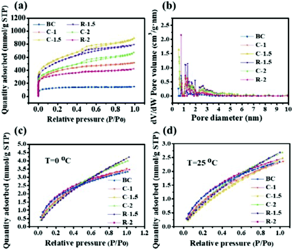
The N2 adsorption–desorption isotherms and pore size distributions of all samples are shown in Fig. 2a and b, respectively. The isotherms of all samples exhibit a relatively high nitrogen uptake at low relative pressure, demonstrating the existence of plentiful micropores. Moreover, no obvious hysteresis loop is observed in the isotherms of BC, C-1, and R-2, indicating numerous micropores (Vmic/Vt = 43.36%, 42.66% and 43.62%, respectively).15,38 Other carbon samples with activation show apparent hysteresis loops at medium relative pressure (P/Po = 0.4–1.0), suggesting that along with abundant micropores, a large quantity of mesopores were generated as well.39
 | ||
| Fig. 2 N2 adsorption–desorption isotherms (a), pore size distributions (b) and CO2 adsorption isotherms measured at 0 (c) and 25 °C (d) of the as-prepared porous carbons. | ||
Particularly, the isotherms of C-1.5, R-1.5 and C-2 display a slight increasing tendency at relatively high pressure (P/Po = 0.95–1.0), indicating the presence of a few macropores.40 Among all samples, C-1.5 displays the highest nitrogen uptake with plentiful micropores, abundant mesopores and a few macropores. The pore size distribution curves (Fig. 2b) calculated using the DFT model reveal that the samples mainly consist of abundant micropores (<2 nm) and small mesopores (2–6 nm), which contribute to fast ion transport for high electric double-layer capacitance.12,13 Particularly, C-1.5 and R-1.5 exhibit sharp peaks at 0.5 nm and 1.3 nm for micropores and intense peaks at 2.4 nm and 2.6 nm for mesopores, respectively, demonstrating a larger pore volume than the other carbon samples.
The SSA and pore structure parameters of the as-prepared cornstalk hierarchical porous carbons (CHPCs) are shown in Table 1. The specific surface area of C-1 (1419 m2 g−1) is much higher than that of C300-800 (482 m2 g−1) without activation. Moreover, the SSA and total pore volume of C-1.5 increase with the weight ratios of the carbon precursor, K2C2O4, and CaCO3 varying from 1:1:1 to 1:1.5:1, while those of C-2 slightly decrease with further increase of K2C2O4 to 1:2:1. The SSAs of C-1, C-1.5 and C-2 are 1419 m2 g−1, 2054 m2 g−1 and 1492 m2 g−1, while their total pore volumes are 0.3704 cm3 g−1, 1.382 cm3 g−1, and 1.043 cm3 g−1, respectively. Compared with C-1.5, C-2 displays a lower SSA and pore volume, which can probably contribute to the collapse of the pore structure under a higher activating agent content. These results show that the dosage of K2C2O4 is the dominating factor for the development of the pore structure.41 The removal of cornstalk pith could also regulate the SSA and porosity of the samples. Although C-1.5 exhibits an SSA of 2054 m2 g−1 and a total pore volume of 1.382 cm3 g−1, which are slightly higher than those of R-1.5 (1910 m2 g−1 and 1.198 cm3 g−1), R-1.5 displays a high Vmes/Vt ratio of 86.89%. Besides, R-2 exhibits a lower SSA and total pore volume than those of C-2, which confirms that the removal of pith from cornstalk leads to the decrease of the SSA. It can be indicated that the intrinsic loose structure of pith is unconducive to generate carbon materials with a high mesopore/micropore ratio.14,42 Thus, the removal of pith from cornstalk plays a crucial role in the formation of the hierarchical structure with rational mesopore volume.
| Samples | Textural properties | Elemental analysis | |||||||
|---|---|---|---|---|---|---|---|---|---|
| S total (m2 g−1) | V t (cm3 g−1) | V mic (cm3 g−1) | V mes (cm3 g−1) | V mic/Vt (%) | V mes/Vt (%) | C (wt%) | N (wt%) | O (wt%) | |
| a S total is the specific surface area obtained from multipoint Brunauer–Emmett–Teller (BET) plots. b V t is the total pore volume determined at P/P0 = 0.99. c V mic and Vmec are the micropore and mesopore volume calculated by the t-plot method. | |||||||||
| BC | 482 | 0.226 | 0.098 | 0.128 | 43.36 | 56.64 | 77.68 | 0.44 | 14.04 |
| C-1 | 1419 | 0.370 | 0.1580 | 0.2124 | 42.66 | 57.34 | 83.63 | 0.84 | 12.01 |
| C-1.5 | 2054 | 1.382 | 0.188 | 1.194 | 13.60 | 86.40 | 84.56 | 0.49 | 11.45 |
| C-2 | 1492 | 1.043 | 0.162 | 0.881 | 15.52 | 84.48 | 86.73 | 0.59 | 10.20 |
| R-1.5 | 1910 | 1.198 | 0.157 | 1.041 | 13.11 | 86.89 | 87.67 | 0.55 | 9.87 |
| R-2 | 1200 | 0.635 | 0.277 | 0.358 | 43.62 | 56.38 | 85.10 | 0.63 | 9.48 |
The CO2 capture capacities of the CHPCs at 273 K and 298 K were measured, as shown in Fig. 2c and d and Table 2. CHPCs have large CO2 uptakes of 2.35–2.70 mmol g−1 (103.40–118.80 mg g−1) and 3.34–4.23 mmol g−1 (146.96–182.16 mg g−1) at 298 K and 273 K, respectively. The CO2 capture capacities of C-1, C-1.5 and C-2 are 2.36, 2.49, and 2.68 mmol g−1 at 298 K, and 3.51, 4.14, and 4.01 mmol g−1 at 273 K, respectively, which are higher than those of BC (2.35 mmol g−1 at 298 K and 3.34 mmol g−1 at 273 K). The results reveal that the CO2 capture capacity is associated with both SSA and porous structures.43 In addition, R-1.5 with a high SSA exhibits an extremely high CO2 capture capacity (2.70 mmol g−1 at 298 K and 4.23 mmol g−1 at 273 K). These results suggest that the CHPCs have promising application in CO2 capture.
| Samples | CO2 uptake at 298 K | CO2 uptake at 273 K | ||
|---|---|---|---|---|
| (mg g−1) | (mmol g−1) | (mg g−1) | (mmol g−1) | |
| BC | 103.40 | 2.35 | 146.96 | 3.34 |
| C-1 | 103.84 | 2.36 | 154.44 | 3.51 |
| C-1.5 | 109.56 | 2.49 | 182.16 | 4.14 |
| C-2 | 117.92 | 2.68 | 176.44 | 4.01 |
| R-1.5 | 118.80 | 2.70 | 186.12 | 4.23 |
| R-2 | 108.68 | 2.47 | 152.68 | 3.47 |
CaCO3 can act as the hard template embedded in the carbon structures to generate hierarchical pores. The following reactions are involved during the high-temperature activation:
| K2C2O4 → 2K2CO3 + CO | (6) |
| K2CO3 + CaCO3 → K2Ca(CO3)2 | (7) |
| K2Ca(CO3)2 + CaCO3 → K2Ca2(CO3)3 | (8) |
| CaCO3 → CaO + O2 | (9) |
| K2Ca2(CO3)3 → K2Ca(CO3)2 + CaO + CO2 | (10) |
| K2Ca(CO3)2 → K2CO3 + CaO + CO2 | (11) |
| K2CO3 + 2C → 2K + 3CO | (12) |
K2CO3 is generated from the decomposition of potassium oxalate (6) and CaCO3 nanoparticles are used as hard templates (7).44 At 700 °C, the decomposition of CaCO3 into CaO is complete (9) and K2Ca2(CO3)3 transforms back to K2Ca(CO3)2(10).45 At 750 °C, K2Ca(CO3)2 decomposes into K2CO3 and CaO (11), so unreacted K2CO3 and CaO are the only species at 800 °C.46 All these changes are supposed to influence the morphology and change the size of the template particles, resulting in the honeycomb-like structure with many interconnected channels. At 700–750 °C, the formation of micropores and small mesopores mainly results from the redox reaction (12) and carbon gasification (9)–(11).41,47 Simultaneously, the large mesopores and macropores are developed owing to the template particles (i.e., K2Ca(CO3)2, K2Ca2(CO3)3, and CaO), giving rise to a much less dense structure than that obtained in the presence of only CaCO3.48,49 In this way, cornstalk carbons with a hierarchical pore structure, large SSA and high meso/micropore ratio were successfully prepared, which has been depicted in the BET results of CHPCs.
To further investigate the micromorphology and microstructure of the hierarchical porous carbons derived from cornstalk rind and pith, SEM and TEM characterization was carried out. As shown in Fig. 3a–f, the SEM images of C-1.5, R-1.5, and P-1.5 clearly reveal that the cornstalk derived carbons obtained from different raw materials present interconnected pore structures. C-1.5 derived from raw cornstalk exhibits a hierarchical cellular structure (Fig. 3a and d) and R-1.5 synthesized from cornstalk without pith displays a staggered and interconnected network structure (Fig. 3b and e). The obtained P-1.5 from pith presents a velvet like structure (Fig. 3c and f). The interconnected macropores of C-1.5 and R-1.5 may serve as ion-buffering reservoirs and ion transport channels, while these densely packed pore walls can provide a large specific surface area for charge storage.50 Besides, raw cornstalk possesses a vascular skeleton with small amounts of pores (Fig. 3g), and the skeleton is broken after carbonization (BC, Fig. 3h). The TEM images (Fig. 3i and j) of C-1.5 and R-1.5 show a large amount of small mesopores and worm-like micropores, which well agrees with the results from N2 adsorption–desorption isotherms. Particularly, R-1.5 (Fig. 3j) demonstrates abundant randomly opened mesopores with a larger size than those in C-1.5, which are well connected with the worm-like micropores. Among them, the mesopores can provide fast diffusion channels and short diffusion distance for ions, while the micropores can offer a large SSA to increase the electrical double layer capacitance.51,52 The cell morphologies of cornstalk pith and rind are shown in Fig. 3k and l. Obvious difference can be observed in the light microscopy images. The cells of the pith are most non-fibrous spongy tissues in a pillow-like and round shape with thin cell walls (Fig. 3k), while the cells of the rind possess a staggered claviform structure with thicker walls and thinner vessels (Fig. 3l). Therefore, cornstalk rind can mostly retain its original shape after carbonization.
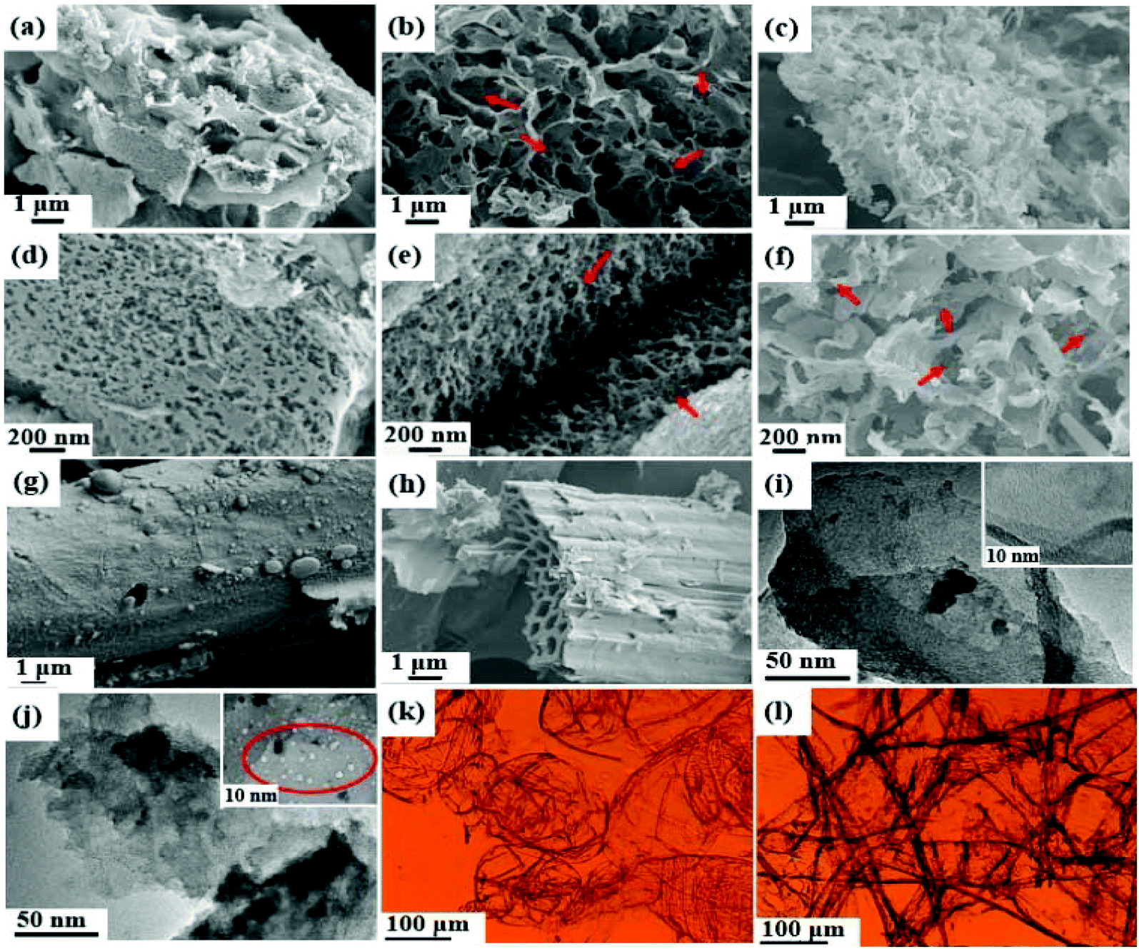 | ||
| Fig. 3 SEM images of C-1.5 (a and d), R-1.5 (b and e), P-1.5 (c and f), raw cornstalk (g) and BC (h). TEM images of C-1.5 (i) and R-1.5 (j). Cell morphology by light microscopy of cornstalk pith (k) and rind (l). | ||
Elemental analysis was also conducted to investigate the chemical composition of the CHPCs, and the results are shown in Table 1. It is clearly seen that C-1, C-1.5, and C-2 have a higher C content (83.63 wt%, 84.56 wt%, and 86.73 wt%) than C300-800 (77.68 wt%). BC shows the highest O content of 14.04%, which demonstrates a large amount of oxygen due to the incomplete carbonization of the cornstalk precursor without activation. With the increase of activators, the oxygen concentrations of C-1, C-1.5, and C-2 decrease gradually from 12.01 wt% to 11.45 wt% and eventually to 10.20 wt%, respectively. The C contents of C-1.5, R-1.5, C-2, and R-2 do not show remarkable difference. Particularly, R-1.5 displays the highest C content of 87.67 wt%, with a N content of 0.55 wt% and an O content of 9.87 wt%. With the addition of K2C2O4, the O contents of C-2 and R-2 decrease to 10.20 wt% and 9.48 wt%, as compared with C-1.5 (11.45 wt%) and R-1.5 (9.87 wt%), which can be attributed to the removal of chemically absorbed oxygen and water from carbon materials with the increase of the activator.53 Compared to C-1.5 and C-2, the O contents of R-1.5 and R-2 decrease, which can be assigned to the removal of pith from cornstalk. The loose and spongy pith with a large amount of non-fibrous structures contains 70% hybrid cells and rich crude fat, protein and carbohydrates. The unique structure and abundant functional groups can impart the product with high oxygen content.19,32,35,53
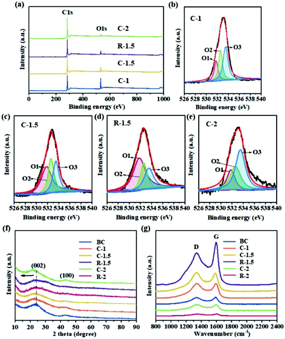
XPS analysis was carried out to further investigate the chemical composition and functional groups of the CHPCs. The XPS survey spectra display two obvious peaks at 284.6 and 533.0 eV, assigned to C 1s and O 1s (Fig. 4a), respectively. Their XPS composition and the relative concentrations of O species obtained by fitting the O 1s spectra are summarized in Table S1.† The C/O atomic ratios of BC, C-1, C-1.5 and C-2 are 1.23, 1.50, 2.20 and 4.64, respectively, indicating the decrease of oxygen content and the increase of graphitization degree. Compared to C-1.5, the C/O atomic ratio of R-1.5 decreases to 2.82, suggesting the reduction of oxygen content and the increase of graphitization degree due to the removal of pith. The O 1s peaks located at 531.8 eV (O1), 532.6 eV (O2) and 533.5 eV (O3) in Fig. 4b–e further demonstrate the existence of quinone and ketone groups (C![[double bond, length as m-dash]](https://www.rsc.org/images/entities/char_e001.gif) O), phenol groups (C–OH) and/or ether groups (C–O–C), and chemisorbed oxygen and/or water, respectively.54 These oxygen-containing functional groups can greatly improve the reactivity and wettability and enhance the conductivity of CRHPCs, increasing their active surface area and inducing pseudo-capacitance in charge and discharge processes.32,55 Particularly, quinone/ketone oxygen, carbonyl and ether oxygen have been considered as important oxygen functionalities on carbon with regard to their electrochemical activity, and the quinone oxygen has been confirmed as the main source of pseudocapacitance.56,57 The X-ray diffraction (XRD) patterns of the CHPCs are shown in Fig. 4f. The two typical broad peaks at around 2θ = 23.4° and 43.5° are assigned to the (002) and (100) reflection peaks of amorphous carbon, suggesting that the carbon products have a low degree of graphitized carbon.58 The (002) peaks of C-1, C-1.5, R-1.5, C-2 and R-2 slightly shift to a lower diffraction angle (2θ = 22.5°, 22.5°, 23.3°, 23.3° and 23.2°, respectively) owing to K2C2O4 activation. After chemical activation, the (002) peak in activated carbons weakens, indicating the destruction of their crystal structure by introducing abundant micropores.59 Raman spectroscopy was conducted to further elucidate the graphitization degree and specific structural features of the CRHPCs, and the results are presented in Fig. 4g. Two distinct characteristic bands located at around 1338 and 1596 cm−1 are ascribed to the D band (defects and disorder) and G band (graphitic carbon), respectively. The intensity ratio of D to G (ID/IG) can be used to manifest the degree of defects and disorder structure of carbon.60 The ID/IG values of BC, C-1, C-1.5, and C-2 are 0.95, 1.00, 1.04 and 1.01, respectively, suggesting that the increase of K2C2O4 dosage (ratio of carbon precursor to K2C2O4 by weight) from 1:1 to 1:1.5 can induce more defects and disorder in the carbon, while further increasing K2C2O4 dosage (1:2) can enhance the graphitization degree of carbon. The ID/IG values of R-1.5 and C-1.5 are 0.75 and 1.04, respectively, indicating a higher graphitization degree of R-1.5, which is in accordance with the XPS result. It is likely that the loose and spongy structure of cornstalk pith can promote defects during activation, thus increasing the disorder degree of carbon materials.53,61 The ID/IG values of R-2 and C-2 are 0.95 and 1.01, respectively, which further demonstrate that the as-obtained carbons from cornstalk without pith have a higher graphitization degree.
O), phenol groups (C–OH) and/or ether groups (C–O–C), and chemisorbed oxygen and/or water, respectively.54 These oxygen-containing functional groups can greatly improve the reactivity and wettability and enhance the conductivity of CRHPCs, increasing their active surface area and inducing pseudo-capacitance in charge and discharge processes.32,55 Particularly, quinone/ketone oxygen, carbonyl and ether oxygen have been considered as important oxygen functionalities on carbon with regard to their electrochemical activity, and the quinone oxygen has been confirmed as the main source of pseudocapacitance.56,57 The X-ray diffraction (XRD) patterns of the CHPCs are shown in Fig. 4f. The two typical broad peaks at around 2θ = 23.4° and 43.5° are assigned to the (002) and (100) reflection peaks of amorphous carbon, suggesting that the carbon products have a low degree of graphitized carbon.58 The (002) peaks of C-1, C-1.5, R-1.5, C-2 and R-2 slightly shift to a lower diffraction angle (2θ = 22.5°, 22.5°, 23.3°, 23.3° and 23.2°, respectively) owing to K2C2O4 activation. After chemical activation, the (002) peak in activated carbons weakens, indicating the destruction of their crystal structure by introducing abundant micropores.59 Raman spectroscopy was conducted to further elucidate the graphitization degree and specific structural features of the CRHPCs, and the results are presented in Fig. 4g. Two distinct characteristic bands located at around 1338 and 1596 cm−1 are ascribed to the D band (defects and disorder) and G band (graphitic carbon), respectively. The intensity ratio of D to G (ID/IG) can be used to manifest the degree of defects and disorder structure of carbon.60 The ID/IG values of BC, C-1, C-1.5, and C-2 are 0.95, 1.00, 1.04 and 1.01, respectively, suggesting that the increase of K2C2O4 dosage (ratio of carbon precursor to K2C2O4 by weight) from 1:1 to 1:1.5 can induce more defects and disorder in the carbon, while further increasing K2C2O4 dosage (1:2) can enhance the graphitization degree of carbon. The ID/IG values of R-1.5 and C-1.5 are 0.75 and 1.04, respectively, indicating a higher graphitization degree of R-1.5, which is in accordance with the XPS result. It is likely that the loose and spongy structure of cornstalk pith can promote defects during activation, thus increasing the disorder degree of carbon materials.53,61 The ID/IG values of R-2 and C-2 are 0.95 and 1.01, respectively, which further demonstrate that the as-obtained carbons from cornstalk without pith have a higher graphitization degree.
 | ||
| Fig. 4 XPS survey spectra of BC, C-1.5, R-1.5, and C-2 (a). High-resolution O 1s spectra of BC (b), C-1.5 (c), R-1.5 (d), and C-2 (e). XRD patterns (f) and Raman spectra (g) of CHPCs. | ||
The electrochemical performances of CHPCs were first investigated using a three-electrode system in 1 M H2SO4 aqueous solution. As shown in Fig. 5a, the CV curves of CHPCs display quasi-rectangular shapes with an obvious hump at 0.2–0.6 V at a scan rate of 20 mV s−1. The hump in the CV plot measured in a three-electrode system indicates redox reactions, which mainly result from the quinone oxygen groups.56 R-1.5 exhibits the largest encircled area among all the carbon samples, revealing the highest capacitance. Fig. 5b shows the GCD curves of the CHPCs at 1.0 A g−1 and all samples exhibit quasi-linear and symmetrical triangular profiles. Apparently, C-1.5 and R-1.5 display longer discharge times, indicating their better supercapacitances. The specific capacitances calculated from the discharge curves of the samples are illustrated in Fig. 5c. C-1.5 and R-1.5 exhibit superior specific capacitances of 337 F g−1 and 387 F g−1 at 1.0 A g−1, respectively, which are obviously higher than those of BC (155 F g−1), C-1 (211 F g−1), C-2 (197 F g−1), and R-2 (237 F g−1). As for C-1.5 and R-1.5, the interconnected porous structure facilitates ion transportation, while the high SSA (2054 m2 g−1 and 1910 m2 g−1) provides sufficient electrode–electrolyte interface for charge storage and the large amount of mesopores is beneficial to the retention and immersion of the electrolyte ions, providing convenient channels for electrolyte penetration and ion transportation.52 Meanwhile, the abundant oxygen-containing functional groups provide additional pseudo-capacitance for the samples.49 Therefore, C-1.5 (337 F g−1) and R-1.5 (387 F g−1) show superb gravimetric specific capacitance among all the CHPCs. Compared with C-1.5, R-1.5 exhibits a higher mesopore ratio (86.89%) and graphitization degree after the removal of pith, which greatly contributes to a higher specific capacitance. In order to compare and further elucidate other electrochemical performances of C-1.5 and R-1.5, CV and GCD measurements at different scan rates and current densities are conducted.
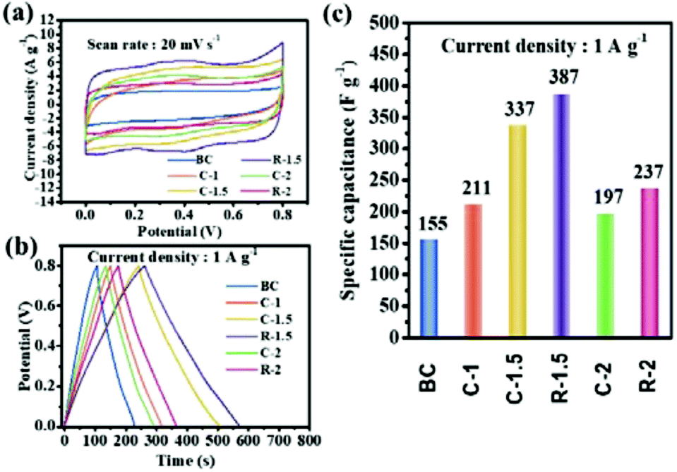 | ||
| Fig. 5 CV curves (a), GCD curves (b), and specific capacitances (c) of the CHPCs. | ||
Fig. 6a and b show the CV curves of C-1.5 and R-1.5 at scan rates ranging from 5 to 200 mV s−1, respectively. The CV curves of C-1.5 (Fig. 6a) exhibit a quasi-rectangular shape, while the CV curves of R-1.5 (Fig. 6b) display a rectangular shape with a hump at 0.2–0.6 V, which can be attributed to the redox reactions induced by the high content of quinone oxygen groups.52 The specific supercapacitances of C-1.5 and R-1.5 calculated from the CV curves are summarized in Fig. 6e. The specific capacitances of C-1.5 and R-1.5 at 5 mV s−1 are as high as 551 F g−1 and 618 F g−1, respectively. Even at a high scan rate (200 mV s−1), R-1.5 still displays a high specific capacitance of 447 F g−1, which is much larger than that of C-1.5 (273 F g−1), indicating a high rate capacity and rapid charge transfer capability. Fig. 6c and d demonstrate the corresponding GCD plots of C-1.5 and R-1.5 at current densities ranging from 0.5 to 20 A g−1. Both C-1.5 and R-1.5 have symmetrical triangular profiles with long discharging time. Particularly, the discharging profile of C-1.5 bends down at the end while that of R-1.5 sets straight ahead, indicating more efficient discharging performances of R-1.5. As shown in Fig. 6f, C-1.5 displays a very high specific capacitance of 472 F g−1 at 0.5 A g−1 but a low specific capacitance of 184 F g−1 at 20 A g−1, revealing only 39.6% capacitance retention. Interestingly, R-1.5 possesses high specific capacitances of 461 F g−1 at 0.5 A g−1 and 291 F g−1 at 20 A g−1, with 63.1% capacitance retention. Compared with C-1.5, R-1.5 shows a similarly large specific capacitance but an exceptionally high capacitance retention, which can be ascribed to its higher mesopore ratio resulting from the removal of pith.
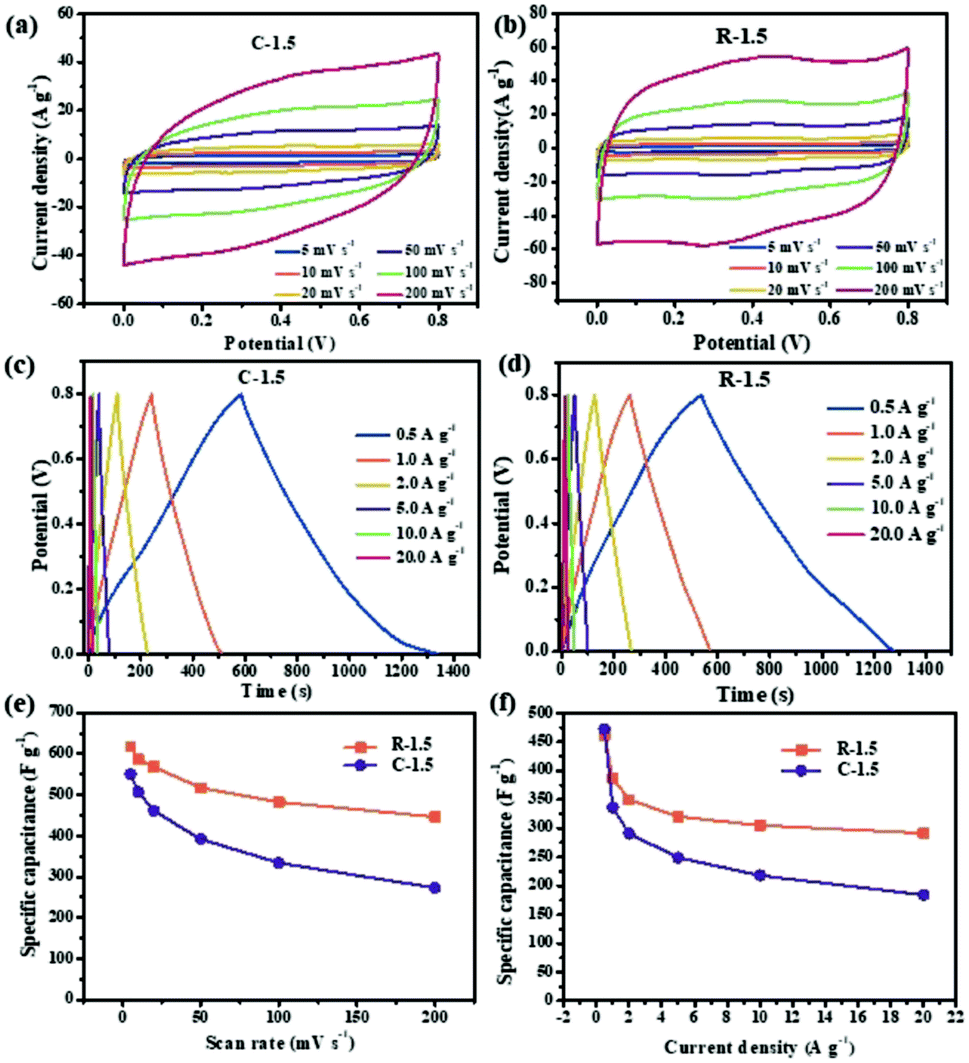 | ||
| Fig. 6 CV curves of C-1.5 (a) and R-1.5 (b) at different scan rates; GCD curves of C-1.5 (c) and R-1.5 (d) at different current densities; specific capacitances calculated from CV curves (e) and GCD curves (f). | ||
Electrochemical impedance spectroscopy (EIS) was conducted to further study the cornstalk-based carbon electrodes. The Nyquist plots of C-1.5 and R-1.5 electrodes in the frequency range from 10 mHz to 10 kHz are displayed in Fig. 7a. The fitting equivalent circuit model by the coupled nonlinear equation (CNLS) method is displayed in Fig. 7a (the inset). The whole capacitor circuit is constituted by Rs, CPE, Rct, Zw and Cf. The internal resistance (Rs) is composed of the electrode resistance, electrolyte resistance and interfacial contact resistance between the active materials and current collector.13 C-1.5, R-1.5, and C-2 exhibit an approximately vertical line along the Z′′ axis in the low frequency region, indicating an almost ideal capacitive behavior and low resistance of ion diffusion in the electrode materials.32 In the high frequency region, the semi-circular behavior is ascribed to the charge transfer resistance (Rct). No distinct semicircle can be observed, demonstrating a small charge transfer resistance (Rct) and fast ion diffusion towards the surface of the electrode.53,61ZW is the Warburg resistance which is related to the ion diffusion/transport in the electrolyte. The CPE and Cf are related to the capacitor layer formed during the charge–discharge process. The relevant parameters are listed in Table 3. The R-1.5 electrode exhibits an Rs value of 4.48 Ω, which is lower than that of C-1.5 (5.30 Ω) and C-2 (9.50 Ω). The result indicates that R-1.5 permits higher accessibility of the electrode surface for electrolyte ions. Additionally, R-1.5 possesses plentiful mesopores, which can provide abundant transport channels, shorten the ion diffusion path and reduce charge transfer resistance, thus resulting in the enhanced conductivity and the lowest Rct.62,63 Furthermore, the cycle-life test evaluated using constant current charge–discharge cycles (Fig. 7b) illustrates that R-1.5 possesses a desirable capacitance of 264 F g−1 after 10000 cycles at a current density of 10.0 A g−1. These results further confirm that with the removal of pith, R-1.5 possesses the lowest internal resistance, the best ion transfer behavior and an excellent cycling performance, which can be attributed to its improved mesopore ratio and enhanced graphitization degree in previous discussion. Consequently, R-1.5 has been considered as a promising carbon electrode material by now in this research. To further evaluate the practical electrochemical properties of R-1.5, CV and GCD tests in a two electrode system are still required.
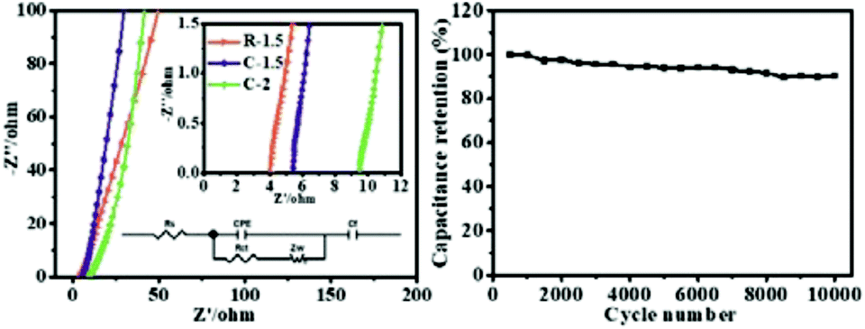 | ||
| Fig. 7 Nyquist plots of C-1.5, R-1.5 and C-2 (a); and cycle stabilities of R-1.5 at a current density of 10.0 A g−1 (b). | ||
| Samples | R s (Ω) | R ct (Ω) | Z w (Ω) | C (F) | Q (F) |
|---|---|---|---|---|---|
| C-1.5 | 5.30 | 0.48 | 3.90 | 4.50 × 10⁻⁵ | 6.59 × 10⁻³ |
| R-1.5 | 4.48 | 0.48 | 3.08 | 6.75 × 10⁻⁵ | 1.68 × 10⁻³ |
| C-2 | 9.50 | 0.57 | 5.85 | 2.79 × 10⁻⁵ | 3.76 × 10⁻³ |
A symmetric device is assembled with R-1.5 by employing two identical electrodes in 1 M Na2SO4 aqueous electrolyte. As shown in Fig. 8a, the R-1.5 symmetric electrode displays quasi-rectangular shapes as the potential window increases and can be operated at 2.0 V with no obvious increase in the anodic current. The CV profiles of the symmetric electrode in Fig. 8b display good rectangular shapes without apparent distortion at a sweep rate of 5–200 mV s−1. The GCD plots (Fig. 8c) of the symmetric electrode show quasi-triangular charge–discharge shapes in a wide range of current density from 0.5 A g−1 to 20 A g−1, indicating excellent electrochemical reversibility. The R-1.5 symmetric electrode displays a high specific capacitance of 306 F g−1 at 1 A g−1 and 240 F g−1 at 20 A g−1 from GCD plots, suggesting a superior capacitance performance and an outstanding rate capability. A high retention rate of 78.0% demonstrates the superior rate capability of R-1.5 due to the efficient ion transportation.14 The specific capacitances of R-1.5 at different current densities are summarized and compared with other biomass-based carbon materials, as shown in Fig. 8d. R-1.5 displays an ultrahigh specific capacitance that exceeds that of most biomass-derived carbons (coloured dots), such as corn stalk core (300 F g−1 at 0.1 A g−1),50 broad beans (129 F g−1 at 10 A g−1),64 corn husk (260 F g−1 at 1.0 A g−1),60 and so on.53,65–69 The Ragone plot in Fig. 8e depicts that R-1.5 has a high energy density of 42.5 W h kg−1 at a power density of 374.1 W kg−1 and 33.3 W h kg−1 at a very high output power density of 9.3 kW kg−1, exceeding those of other biomass-based carbons (coloured dots in Fig. 8e).50,60,69–75 To further demonstrate the practical application of R-1.5 as an electrode material, a green light-emitting diode (LED) was connected to three as-assembled R-1.5 supercapacitor devices in series. As shown in Fig. 8f, the green LED was lit up brightly for more than 3 min, revealing its practical application for high-performance energy storage systems.
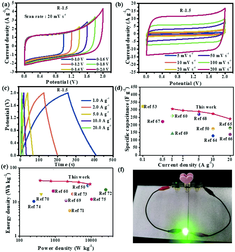 | ||
| Fig. 8 CV curves of the R-1.5 symmetrical supercapacitor at different operation voltages at a scan rate of 20 mV s−1 (a); CV curves of the R-1.5 symmetrical supercapacitor at different scan rates (b); GCD curves of the R-1.5 symmetrical supercapacitor at different current densities (c); specific capacitances for a single electrode at different current densities (d); Ragone plots compared with those of other carbon materials in aqueous electrolyte (e); LEDs are lit up by using R-1.5 as an electrode material (f). | ||
Based on the above discussion, the removal of pith especially endows R-1.5 with a high mesopore ratio and graphitization degree, which are favourable for a decreased internal resistance and an enhanced capacitive behavior. The superior electrochemical performances of R-1.5 benefit from the following features. (i) A large specific area provides abundant active sites for electrolyte ion storage, which leads to high supercapacitance and energy density. (ii) The hierarchical pore structure (micro-, meso- and macropores) offers fast pathways for ion diffusion, which minimizes transport resistances for electrolyte ion movement inside the inner nanopores, thus leading to remarkable rate capability and power density. (iii) The amorphous structure and relatively low graphitization degree of the carbon matrix provide sufficiently long distance for ion shuttling, resulting in low internal resistance and enhanced electrical conductivity, thereby maintaining the high rate performance. (iv) Abundant oxygen-containing groups improve the wettability of active materials, giving rise to the high accessible surface area for ions and extra pseudo-capacitance. These features endow R-1.5 with high specific capacitance, outstanding rate capability, excellent cycling stability and high energy density, which make it a promising candidate as an electrode material for high-performance supercapacitors.
4. Conclusions
In summary, hierarchical porous carbons are successfully prepared from cornstalk without pith for the first time using a facile and scalable approach. With the simple removal of pith, the obtained carbon materials display an improved mesopore ratio and enhanced graphitization degree, resulting in fast ion diffusion and superior rate capability of the carbon electrode. In addition, the reaction of CaCO3 and the activating agent K2C2O4 (potassium oxalate) gives rise to an etching effect and gasification, which can tailor the porosity of the carbon. Benefiting from the large specific surface area and oxygen content, the symmetric device assembled with 1.5XAC-300800 possesses an ultrahigh specific capacitance, excellent rate capability, long-term cycling stability, and high energy density. The simple strategy of pith removal from cornstalk provides a scalable route for low-cost production of advanced hierarchical porous carbons with superior capacitance, energy density and rate capacity.Conflicts of interest
The authors declare no conflicts of interest.Acknowledgements
This work was financially supported by the National Natural Science Foundation of China (No. 51403069 and 31430092), the Science and Technology Planning Project of Guangzhou City (No. 201707010190), and the Fundamental Research Funds for the Central Universities, SCUT (No. 2017ZX003). The authors would like to thank Shiyanjia Lab for the BET analysis (http://www.shiyanjia.com). Jiaming Li especially wishes to thank N. Flying for their spiritual support in the past year, and the dynamic drummer Kim Jae-hyun is her biggest inspiration.References
- S. Yang, Y. Zhu, C. Cao, L. Peng, W. L. Queen and W. Song, ACS Appl. Mater. Interfaces, 2018, 10, 19664–19672 CrossRef CAS PubMed.
- G. L. Vignoles, A. Turchi, D. Bianchi, P. Blaineau, X. Lamboley, D. L. Q. Huy, C. Levet, O. Caty and O. Chazot, Carbon, 2018, 134, 376–390 CrossRef CAS.
- B. Nagy, I. Bakos and K. László, Carbon, 2018, 139, 872–879 CrossRef CAS.
- S. W. L. Ng, G. Yilmaz, W. L. Ong and G. W. Ho, Appl. Catal., B, 2018, 220, 533–541 CrossRef CAS.
- F. E. C. Othman, N. Yusof, H. Hasbullah, J. Jaafar, A. F. Ismail, N. Abdullah, N. A. H. M. Nordin, F. Aziz and W. N. W. Salleh, J. Ind. Eng. Chem., 2017, 51, 281–287 CrossRef.
- K. Kawase, J. Abe, M. Tenjimbayashi, Y. Kobayashi, K. Takahashi and S. Shiratori, ACS Appl. Mater. Interfaces, 2018, 10, 15742–15750 CrossRef CAS PubMed.
- A. D. Adhikari, R. Oraon, S. K. Tiwari, P. Saren, J. H. Lee, N. H. Kim and G. C. Nayak, Ind. Eng. Chem. Res., 2017, 57, 1350–1360 CrossRef.
- A. Pedico, A. Lamberti, A. Gigot, M. Fontana, F. Bella, P. Rivolo, M. Cocuzza and C. F. Pirri, ACS Appl. Energy Mater., 2018, 1, 4440–4447 CrossRef CAS.
- M. Sivachidambaram, J. J. Vijaya, L. J. Kennedy, R. Jothiramalingam, H. A. Al-Lohedan, M. A. Munusamy, E. Elanthamilan and J. P. Merlin, New J. Chem., 2017, 41, 3939–3949 RSC.
- M. Y. Bhat, N. Yadav and S. A. Hashmi, Electrochim. Acta, 2019, 304, 94–108 CrossRef CAS.
- S. Dutta, A. Bhaumik and K. C. W. Wu, Energy Environ. Sci., 2014, 7, 3574–3592 RSC.
- G. Zhao, C. Chen, D. Yu, L. Sun, C. Yang, H. Zhang, Y. Sun, F. Besenbacher and M. Yu, Nano Energy, 2018, 47, 547–555 CrossRef CAS.
- L. Ma, J. Liu, S. Lv, Q. Zhou, X. Shen, S. Mo and H. Tong, J. Mater. Chem. A, 2019, 13, 7591–7603 RSC.
- L. Hao, G. X. S. Zhao and L. Hao, Sustainable Energy Fuels, 2017, 6, 1265–1281 Search PubMed.
- Z. Chen, H. Zhuo, Y. Hu, L. Zhong, X. Peng, S. Jing, Q. Liu, X. Zhang, C. Liu and R. Sun, ACS Sustainable Chem. Eng., 2018, 6, 7138–7150 CrossRef CAS.
- G. Ma, F. Hua, K. Sun, Z. Zhang, E. Feng, H. Peng and Z. Lei, RSC Adv., 2016, 6, 103508–103516 RSC.
- N. Guo, M. Li, Y. Wang, X. Sun, F. Wang and R. Yang, RSC Adv., 2016, 6, 101372–101379 RSC.
- X. Zhang, Y. Zhong, X. Xia, Y. Xia, D. Wang, C. Zhou, W. Tang, X. Wang, J. B. Wu and J. Tu, ACS Appl. Mater. Interfaces, 2018, 10, 13598–13605 CrossRef CAS PubMed.
- X. F. Zhang, B. Wang, J. Yu, X. N. Wu, Y. H. Zang, H. C. Gao, P. C. Su and S. Q. Hao, RSC Adv., 2018, 8, 1159–1167 RSC.
- M. Karnan, K. Subramani, P. K. Srividhya and M. Sathish, Electrochim. Acta, 2017, 228, 586–596 CrossRef CAS.
- M. Genovese, J. Jiang, K. Lian and N. Holm, J. Mater. Chem. A, 2015, 3, 2903–2913 RSC.
- S. Ghosh, R. Santhosh, S. Jeniffer, V. Raghavan, G. Jacob, K. Nanaji and A. N. Grace, Sci. Rep., 2019, 9, 1–15 CrossRef PubMed.
- F. Ma, S. Song, G. Wu, M. Di, W. Geng and J. Wan, J. Mater. Chem. A, 2015, 3, 18154–18162 RSC.
- A. C. Nwanya, M. M. Ndipingwi, N. Mayedwaa, L. C. Razanamahandry, C. O. Ikpo, T. Waryo and E. I. Iwuoha, Electrochim. Acta, 2019, 301, 436–448 CrossRef CAS.
- T. Mitravinda, K. Nanaji, S. Anandan, A. Jyothirmayi, V. S. K. Chakravadhanula, C. S. Sharma and T. N. Rao, J. Electrochem. Soc., 2018, 165, 3369–3379 CrossRef.
- K. Sun, Z. Zhang, H. Peng, G. Zhao, G. Ma and Z. Lei, Mater. Chem. Phys., 2018, 218, 229–238 CrossRef CAS.
- M. Gopiraman, D. Deng, B. S. Kim, I. M. Chung and I. S. Kim, Appl. Surf. Sci., 2017, 409, 52–59 CrossRef CAS.
- M. S. Balathanigaimani, W. G. Shim, M. J. Lee, C. Kim, J. W. Lee and H. Moon, Electrochem. Commun., 2008, 10, 868–871 CrossRef CAS.
- N. Guo, M. Li, Y. Wang, X. Sun, F. Wang and R. Yang, ACS Appl. Mater. Interfaces, 2016, 8, 33626–33634 CrossRef CAS PubMed.
- L. Wang, G. Mu, C. Tian, L. Sun, W. Zhou, P. Yu, J. Yin and H. Fu, ChemSusChem, 2013, 6, 880–889 CrossRef CAS PubMed.
- Z. Yang, H. Lei, Y. Zhang, K. Qian, E. Villota, M. Qian, Y. G. adavalli and S. Hua, Appl. Energy, 2018, 220, 426–436 CrossRef CAS.
- C. Wang, D. Wu, H. Wang, X. Fang, Z. Gao and J. Kai, J. Mater. Chem. A, 2018, 6, 1244–1254 RSC.
- H. Yu, W. Zhang, T. Li, L. Zhi, L. Dang, Z. Liu and Z. Lei, RSC Adv., 2017, 7, 1067–1074 RSC.
- J. Wang, P. Nie, B. Ding, S. Dong, X. Hao, H. Dou and X. Zhang, J. Mater. Chem. A, 2017, 5, 2411–2428 RSC.
- Z. Li, H. Zhai, Z. Yan and Y. Li, Ind. Crops Prod., 2012, 37, 130–136 CrossRef CAS.
- T. Liu, Z. Feng, S. Yu and Y. Li, J. Mater. Chem. A, 2017, 5, 17705–17733 RSC.
- L. Su, J. Hei, X. Wu, L. Wang and Y. Wang, ChemElectroChem, 2015, 2, 1897–1902 CrossRef CAS.
- S. M. Alatalo, E. Mäkilä, E. Repo, M. Heinonen, J. Salonen, E. Kukk, M. Sillanpää and M.-M. Titirici, Green Chem., 2016, 18, 1137–1146 RSC.
- Y. Lu, S. Zhang, J. Yin, C. Bai, J. Zhang, Y. Li, Y. Yang, G. Zhen, Z. Miao and W. Lei, Carbon, 2017, 124, 64–71 CrossRef CAS.
- Y. Qing, Y. Jiang, H. Lin, L. Wang and Z. Fan, J. Mater. Chem. A, 2019, 7, 6021–6027 RSC.
- D. C. Huang, Q. L. Liu, W. Zhang, J. Ding, J. J. Gu, S. M. Zhu, Q. X. Guo and D. Zhang, J. Mater. Sci., 2011, 46, 5064–5070 CrossRef CAS.
- S. De, A. M. Balu, J. C. van der Waal and R. Luque, ChemCatChem, 2015, 7, 1608–1629 CrossRef CAS.
- A. S. Jalilov, G. Ruan, C. C. Hwang, D. E. Schipper, J. J. Tour, Y. Li and J. M. Tour, Appl. Surf. Sci., 2015, 7, 1376–1382 CAS.
- Y. D. Chen, W. Q. Chen, B. Huang and M. J. Huang, Chem. Eng. Res. Des., 2013, 91, 1783–1789 CrossRef CAS.
- M. Sevilla, G. Ferrero and A. B. Fuertes, Chem. Mater., 2017, 29, 6900–6907 CrossRef CAS.
- M. Blander, K. W. Ragland, R. L. Cole, J. A. Libera and A. Pelton, Biomass Bioenergy, 1995, 8, 29–38 CrossRef CAS.
- L. Yue, Q. Xia, L. Wang, L. Wang, H. Dacosta, J. Yang and X. Hu, J. Colloid Inter. Sci., 2017, 511, 259–267 CrossRef PubMed.
- X. Chen, Y. Chen, H. Yang, W. Chen, X. Wang and H. Chen, Bioresour. Technol., 2017, 233, 15–20 CrossRef CAS PubMed.
- A. Navrotsky, R. L. Putnam, C. Winbo and E. Rosen, Am. Mineral., 1997, 82, 546–548 CAS.
- Y. Liu, Z. Xiao, Y. Liu and L. Z. Fan, J. Mater. Chem. A, 2018, 6, 160–166 RSC.
- L. Zhang, T. You, T. Zhou, X. Zhou and F. Xu, ACS Appl. Mater. Interfaces, 2016, 8, 13918–13925 CrossRef CAS PubMed.
- A. Sanchez-Sanchez, J. Mater. Chem. A, 2016, 4, 6140–6148 RSC.
- Y. Cao, K. Wang, X. Wang, Z. Gu, Q. Fan, W. Gibbons, J. D. Hoefelmeyer, P. R. Kharel and M. Shrestha, Electrochim. Acta, 2016, 212, 839–847 CrossRef CAS.
- Z. Rui, X. Jin, Y. Chu, W. Lei, W. Kang, D. Wei, H. Li and S. Xiong, J. Mater. Chem. A, 2018, 6, 17730–17739 RSC.
- W. Yu, H. Wang, L. Shuang, M. Nan, L. Xiao, S. Jing, L. Wei, S. Chen and W. Xin, J. Mater. Chem. A, 2016, 4, 5973–5983 RSC.
- M. Seredych, D. Hulicova-Jurcakova, G. Q. Lu and T. J. Bandosz, Carbon, 2008, 46, 1475–1488 CrossRef CAS.
- M. F. Dupont and S. W. Donne, J. Electrochem. Soc., 2015, 162, 1246–1254 CrossRef.
- M. Liu, L. Gan, W. Xiong, Z. Xu, D. Zhu and L. Chen, J. Mater. Chem. A, 2014, 2, 2555–2562 RSC.
- M. Xu, Q. Huang, R. Sun and X. Wang, RSC Adv., 2016, 6, 88674–88682 RSC.
- S. Song, F. Ma, G. Wu, D. Ma, W. Geng and J. Wan, J. Mater. Chem. A, 2015, 3, 18154–18162 RSC.
- H. Xu, H. Zhang, Y. Ouyang, L. Li and W. Yu, Electrochim. Acta, 2016, 214, 119–128 CrossRef CAS.
- J. Cao, C. Zhu, Y. Aoki and H. Habazaki, ACS Sustainable Chem. Eng., 2018, 6, 7292–7303 CrossRef CAS.
- X. Wang, S. Yun, W. Fang, C. Zhang, X. Liang, Z. Lei and Z. Liu, ACS Sustainable Chem. Eng., 2018, 6, 11397–11407 CrossRef CAS.
- G. Xu, J. Han, D. Bing, N. Ping, P. Jin, D. Hui, H. Li and X. Zhang, Green Chem., 2015, 17, 1668–1674 RSC.
- W. Yong, Y. Ru, L. Min and Z. Zhao, Ind. Crops Prod., 2015, 65, 216–226 CrossRef.
- X. Lu, C. Jiang, Y. Hu, H. Zhong, Z. Yang, X. Xu and H. Liu, J. Appl. Electrochem., 2018, 48, 233–241 CrossRef CAS.
- L. Jing, W. Liu, X. Dan and X. Wang, Appl. Surf. Sci., 2017, 416, 918–924 CrossRef.
- C. Wang, D. Wu, H. Wang, Z. Gao, F. Xu and K. Jiang, J. Colloid Interface Sci., 2018, 523, 133–143 CrossRef CAS.
- B. Zhu, B. Liu, Q. Chong, Z. Hao, W. Guo, Z. Liang, C. Feng and R. Zou, J. Mater. Chem. A, 2018, 6, 1523–1530 RSC.
- C. D. Tran, H. C. Ho, J. K. Keum, J. Chen, N. C. Gallego and A. K. Naskar, Energy Technol., 2017, 5, 1927–1935 CrossRef CAS.
- Z. Chen, X. Peng, X. Zhang, S. Jing, L. Zhong and R. Sun, Carbohydr. Polym., 2017, 170, 107–116 CrossRef CAS PubMed.
- N. Guo, M. Li, X. Sun, F. Wang and R. Yang, Green Chem., 2017, 19, 2595–2602 RSC.
- X. Liu, X. Liu, B. Sun, H. Zhou, A. Fu, Y. Wang, Y. G. Guo, P. Guo and H. Li, Carbon, 2018, 130, 680–691 CrossRef CAS.
- J. Liu, Y. Deng, X. Li and L. Wang, ACS Sustainable Chem. Eng., 2016, 4, 177–187 CrossRef CAS.
- J. S. Wei, S. Wan, P. Zhang, H. Ding, X. B. Chen, H. M. Xiong, S. Gao and X. Wei, New J. Chem., 2018, 42, 6763–6769 RSC.
Footnotes |
| † Electronic supplementary information (ESI) available. See DOI: 10.1039/c9ta07864a |
| ‡ These authors contributed equally to this work. |
| This journal is © The Royal Society of Chemistry 2020 |