
 Open Access Article
 This Open Access Article is licensed under a Creative Commons Attribution-Non Commercial 3.0 Unported Licence
Micellar structure and transformations in sodium alkylbenzenesulfonate (NaLAS) aqueous solutions: effects of concentration, temperature, and salt†
Aysha S.
Rafique
a,
Sepideh
Khodaparast‡
 a,
Andreas S.
Poulos
a,
William N.
Sharratt
a,
Eric S. J.
Robles
b and
João T.
Cabral
*a
a,
Andreas S.
Poulos
a,
William N.
Sharratt
a,
Eric S. J.
Robles
b and
João T.
Cabral
*a
aDepartment of Chemical Engineering, Imperial College London, London SW7 2AZ, UK. E-mail: j.cabral@imperial.ac.uk
bThe Procter & Gamble Company, Newcastle Innovation Centre, Newcastle-Upon-Tyne, NE12 9TS, UK
First published on 27th July 2020
Abstract
We investigate the shape, dimensions, and transformation pathways of micelles of linear sodium alkylbenzenesulfonate (NaLAS), a common anionic surfactant, in aqueous solution. Employing Small Angle Neutron Scattering (SANS) and surface tensiometry, we quantify the effects of surfactant concentration (0.6–15 wt%), temperature (5–40 °C) and added salt (≤0.35 M Na2SO4). Spherical micelles form at low NaLAS (≤2.6 wt%) concentration in water, and become elongated with increasing concentration and decreasing temperature. Addition of salt reduces the critical micelle concentration (CMC) and thus promotes the formation of micelles. At fixed NaLAS concentration, salt addition causes spherical micelles to grow into cylindrical micelles, and then multilamellar vesicles (MLVs), which we examine by SANS and cryo-TEM. Above a threshold salt concentration, the MLVs reach diameters of 100 s of nm to few μm, eventually causing precipitation. While the salt concentrations associated with the micelle-to-cylinder transformation increase only slightly with temperature, those required for the cylinder-to-MLV transformation exhibit a pronounced, linear temperature dependence, which we examine in detail. Our study establishes a solution structure map for this model anionic surfactant in water, quantifying the combined roles of concentration, temperature and salt, at practically relevant conditions.
1 Introduction
Surfactants are key components in numerous global formulations industries including personal and home care, food, coatings, pharmaceuticals, and agri-chemicals.1–7 Owing to their amphiphilic structure many surfactants have high solubility in water, exhibiting complex lyotropic behaviour above a critical concentration.8–12 In dilute solutions (typically below 20–30 wt%), surfactants form globular or more elongated micelles with dimensions of a few nanometers, within an isotropic fluid.13–15 The shape, size and structure of micelles at the nanoscale determine the physical properties and functionality of the surfactant solution.16–18 At higher concentrations, ordered liquid crystalline phases, such as hexagonal, cubic and lamellar phases commonly form.9,10 Understanding the phase boundaries of surfactant systems as a function of concentration, temperature, and the presence of other additives, is central to the design of formulated products, influencing their efficiency in application and environmental impact.Sodium linear alkylbenzenesulfonate, NaLAS, is one of the most commonly used anionic surfactants in the world, employed extensively in detergent formulations.19 It is itself composed of several compounds which differ in alkyl chain length and phenyl isomer whose distributions are depicted in Fig. 1a. In practical applications NaLAS is often found at concentrations below 30 wt% and in the micellar phase. However, structural analyses of this phase and the effect of environmental variations intrinsic to its use, such as dilution, temperature, and presence of electrolytes in water, are largely missing in the literature. Previous studies have reported the existence of mixed micellar (L1) and lamellar phases (Lα) for concentrations above 30 wt% of NaLAS. At such concentrations, a temperature increase above 30 °C was observed to modify the bilayer spacing of the lamellar phase, resulting in lateral phase separation and coexistence of multiple lamellar phases. This has been associated with the presence of multiple isomers or due to the increased ionic strength and the resulting interactions between the headgroup and the counter-ion.20–22 In general, higher temperatures were found to yield a larger bilayer d-spacing, and this effect was more pronounced at lower NaLAS concentrations.21 Below 30 wt%, the micellar phase of NaLAS has been reported to spontaneously transform into multilamellar vesicles (MLVs) upon cooling from room temperature (Fig. 1b).23,24
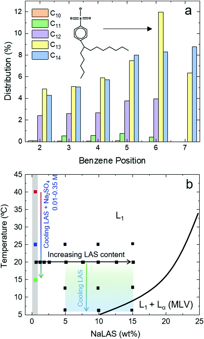 | ||
| Fig. 1 (a) Distribution of phenyl positional isomers with different alkyl chain lengths in an industrial mixture of NaLAS. The chemical structure of the (most abundant) 6-phenyl isomer of NaLAS with a C13 chain is illustrated. (b) Phase diagram of NaLAS/H2O (adapted from ref. 23), showing the regions corresponding to the micellar L1 and the mixed L1 + Lα (here MLVs) phases at relatively lower concentrations (<30 wt%). The filled black square markers indicate experimentally measured data for characterisation of effects of NaLAS concentration (0.5–15 wt%) and temperature (25 °C down to 6 °C) in binary NaLAS/water systems. The grey shaded area refers to measurements of selected ternary mixtures at 0.5 wt% NaLAS with varying amounts of added Na2SO4 salt (0.01–0.35 M) which were analysed at three distinct temperatures. | ||
The effect of surfactant concentration on the shape and size of their micelles has been extensively reported for anionic, cationic and zwitterionic surfactants using small angle X-ray and neutron scattering techniques (SAXS and SANS).25–27 Heating solutions of anionic sodium dodecyl sulfate (SDS) above room temperature was found to shrink ellipsoidal micelles.26,28 Low-concentration surfactant solutions with longer alkyl chain lengths display large differences in viscosity over small increases in concentration that are often associated with changes of micellar structure from spherical to prolate ellipsoids and cylinders.10 Interactions of surfactant molecules with soluble electrolytes in solution often occur as the result of either deliberate addition of salt in formulated products to achieve the desired functionality, or through the electrolytes already present in water. Generally, electrolyte ions reduce the repulsion between surfactant monomer ionic headgroups thereby making it more thermodynamically favourable to form micelles at lower surfactant concentrations.29 The effect of electrolytes on the surface tension and critical micelle concentration (CMC) of surfactant solutions has been extensively reported over several decades;10,30–32 salt addition typically reduces the surface tension of anionic surfactant solutions, with the effect becoming more pronounced at higher salt concentrations,33–35 associated with the electrostatic interactions which promote the migration of surfactant monomers to the interface.10,29,33,35,36
The effect of added electrolytes on anionic micelles at surfactant concentrations above the CMC (in particular of SDS) has been extensively reported in terms of micelle shape, size, and thus functionality of the solution. The addition of sodium and lithium chloride were found to screen the intra- and inter-micelle repulsive forces, thus allowing the formation of larger aggregates.37 SDS micelles have been shown to swell in the presence of other electrolytes.38,39 Upon addition of sufficient salt, and often for multivalent ions common in ‘hard’ water (Ca2+, Mg2+), precipitation occurs. While significant effort has been dedicated to characterising the effect of electrolytes and temperature variations on the bulk properties of industrial surfactant solutions (e.g., CMC, surface tension, detergency and solubility),40,41 their impact on molecular-level structural transformations remains less understood.
In this paper, we seek to elucidate the effects of surfactant concentration, added salt and temperature – relevant to practical utilisation – on the shape, size and structure of NaLAS micelles in aqueous solution. Surface tensiometry is used to determine the CMC and establish the micellar region at varying salt concentration. We employ dynamic light scattering (DLS), SANS and cryogenic transmission electron microscopy (cryo-TEM) in the micellar phase to quantify effects of: (i) surfactant concentration (within a broad range 0.5–15 wt%), (ii) salt concentration (0.01–0.35 M of Na2SO4), and (iii) temperature variations above and below room temperature, as illustrated schematically in Fig. 1b. Our main goal is to identify and quantitatively characterise the pathways that lead to significant structural transformations within the micellar phase of NaLAS.
2 Materials and methods
A surfactant solution of 45 wt% NaLAS in water (H2O), with isomer distribution shown in Fig. 1a, was obtained from Procter & Gamble and used as received. At this concentration and at room temperature the solution was heterogeneous, and it was thus heated at 65 °C for two hours and vigorously mixed to ensure its homogeneity before preparing the various solution series. Na2SO4 (99% purity) was purchased from Sigma Aldrich and used as received. Solutions were prepared by mass and stored at room temperature. Surface tension measurements and electron microscopy analyses were performed on solutions prepared by diluting the original NaLAS solution in DI water and stored at room temperature. To confirm sample homogeneity, surface tension and DLS measurements were carried out 3 times using freshly made solutions from the same batch source. For SANS measurements, the homogenised 45 wt% NaLAS was further diluted in D2O, thereby yielding NaLAS in isotopic water (H2O/D2O) mixtures of known ratio, relevant for background subtraction. Independent SANS measurements, performed on binary and ternary solutions of different NaLAS batches, show good agreement and corroborate the findings presented here (ESI,† Fig. S1 and S2).2.1 Surface tension measurements
Surface tension measurements were carried out using the pendant drop method by Krüss EasyDrop Standard drop shape analysis system (DSA1). A series of NaLAS solutions ranging from 0 wt% to 2 wt% were prepared and made up to the desired concentration of Na2SO4. All samples were left overnight at room temperature prior to measurement. A drop of the filtered surfactant solution was dispensed under gravity using a blunt needle (di = 0.5 mm) and imaged optically. Experiments were repeated five times per sample, with ten surface tension measurements taken per droplet formed. The final surface tension measurement was reported as an average of all readings and with maximum estimated errors.2.2 Dynamic light scattering
DLS measurements were performed on a Zetasizer Nano Z (Malvern Panalytical), equipped with a He–Ne laser of λ = 633 nm. A series of dilutions was made with varying concentrations of Na2SO4. Samples were filtered using a 0.2 μm syringe filter (ThermoFisher Scientific) before being loaded into a glass cuvette sealed with a screw cap (10 mm, Starna Scientific Ltd) to minimise evaporation, and allowed to thermally equilibrate at 25 °C for 5 min prior to data acquisition. Measurements were repeated three times using a fresh batch of dilutions from the stock NaLAS solution. Details of the estimation of hydrodynamic radii can be found in ESI,† Section S2.2.3 Small angle neutron scattering
Solutions of NaLAS in H2O/D2O were prepared at different weight concentrations 0.6–15 wt% and SANS measurements were performed across a wide range of temperatures (5–25 °C). The effect of added salt was examined with solutions of 0.5 wt% NaLAS and 9 different concentrations of Na2SO4 (0–0.35 M), filtered using a 0.2 μm syringe filter (Thomas Scientific) and loaded into quartz cells (1 mm path length banjo, Starna); these measurements were carried out at 15, 25 and 40 °C. The range of NaLAS concentrations and temperatures covered in SANS experiments are illustrated in Fig. 1b. The measurements for NaLAS in water were performed at the D22 diffractometer (Institut Laue Langevin, Grenoble, France) using incident monochromatic λ = 6 Å and Δλ/λ ≃ 10% and those with added salt at varying temperature at LARMOR (ISIS, Didcot, UK) with a polychromatic λ = 0.9–13.3 Å beam with a sample-to-detector distance of 4.1 m. This yielded a range of 0.007 ≤ Q ≤ 0.5 Å−1. SANS data were reduced using GRASP and MANTID (for ILL and ISIS data, respectively)42,43 by subtracting the scattering of the empty cell, and the correct H2O/D2O background, to yield the coherent scattering signal, and fitted with SASView.442.4 Cryo-TEM
A 3 μL droplet of sample solution was placed onto a copper TEM grid covered with a perforated carbon film in a controlled environment vitrifaction system (Vitrobot) at 25 °C and 95% humidity. The excess solution was removed via blotting with filter paper for 3 s. The sample was then placed into liquid ethane prior to storage in liquid nitrogen. The sample was examined with a Tecnai G2 Spirit Twin TEM at 120 kV and the images were captured using a CCD camera (FEI 2K Eagle Camera).3 Results and discussion
We first report on the effects of surfactant concentration and temperature on the shape and dimensions of NaLAS micelles in water, based on SANS data from solutions above the CMC. We then focus on the effect of added salt on the formation of micelles, their shape, size, and finally the pathways of transformations from spherical micelles to elongated cylinders and eventually multilamellar vesicles.3.1 Binary solutions of NaLAS/water
SANS experiments were carried out on solutions of NaLAS ranging from 0.6 to 15 wt%. Scattering Length Densities (SLD) of the sodium sulfonate shells (≃5 Å thickness) and carbon chain tails (≃13–15 Å length) were initialised at 1.69 × 10⁻⁶ Å−2 and −0.46 × 10⁻⁶ Å−2, respectively, based on our previous work.23 For clarity, details of SLD calculations and profiles are provided in ESI,† Section S3. No significant variation in the fitted SLD values were found upon increasing the concentration of NaLAS in binary mixtures, see ESI,† Fig. S5. Fig. 2a shows the SANS data and fits obtained with a core–shell prolate ellipsoidal model for the form factor P(Q), and the Hayter–Penfold Rescaled Mean Spherical Approximation RMSA for the structure factor, S(Q),22,23,28,45 available in SASView.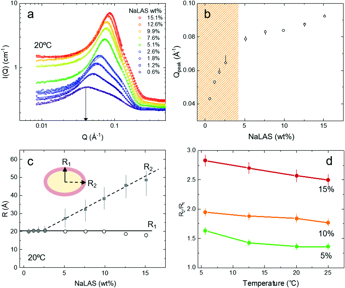 | ||
| Fig. 2 SANS measurements of aqueous micellar solutions of NaLAS at different concentrations and temperatures. (a) Experimental SANS data (open circles) and the corresponding fitted model (solid lines) for increasing concentrations of aqueous NaLAS in water ranging from 0.6 wt% to 15.1 wt%. (b) Variation of the location of the peak Qpeak as a function of concentration of NaLAS wt%. Qpeak is obtained from plotting structure factor S(Q) against Q (Å−1) presented in ESI,† Fig. S7. Due to the change in the shape and size of the micelles two distinct regions were found for concentrations below and above 5 wt% of NaLAS. (c) For ellipsoidal micelles of NaLAS, the minor axis R1 of the fitted ellipsoidal micelles remains unchanged, while the major axis R2 elongates when increasing the concentration of NaLAS at a fixed temperature (here 20 °C). (d) The axial ratio of the micelles R2/R1 increases with decreasing temperature for different concentrations of NaLAS. | ||
Over the concentration range investigated, the scattering intensity curves of Fig. 2a exhibit a broad peak in the mid-Q region, characteristic of both inter- and intramicellar features of charged colloidal suspensions.46,47 Upon increasing NaLAS concentration, the peak shifts towards higher Q and the shoulder appears steeper. The structure factor S(Q) profile can be estimated from the coherent, calibrated scattering intensity as S(Q) = Icorr(Q)/P(Q) (ESI,† Fig. S7), whose peak location Qpeak is shown in Fig. 2b, as a function of concentration. Two distinct trends are observed for concentrations below and above ∼5 wt% NaLAS, suggesting a change in micellar shape and size. In simple terms, assuming an ensemble of spherical micelles whose size remains constant and only the number density increases with volumetric concentration of surfactant C, the location of the peak at Q for each scattering profile would approximately follow log![[thin space (1/6-em)]](https://www.rsc.org/images/entities/char_2009.gif) Q ∝ logC1/3. However, if micelles grow in size and also evolve in shape, a dependence logQ ∝ logCα where α < 1/3 might be expected.48 While Fig. 2b shows Qpeak obtained from S(Q), ESI,† Fig. S7 also includes the peak location obtained from the total scattering intensity (and thus model-free), over the range of concentrations studied here. The trends are similar: for surfactant concentrations <5 wt%, α ≈ 0.23, while α decreases to ≈0.13 for higher concentrations, suggesting the formation of larger micelles yielding a smaller number density than expected for invariant micelle size.49
Q ∝ logC1/3. However, if micelles grow in size and also evolve in shape, a dependence logQ ∝ logCα where α < 1/3 might be expected.48 While Fig. 2b shows Qpeak obtained from S(Q), ESI,† Fig. S7 also includes the peak location obtained from the total scattering intensity (and thus model-free), over the range of concentrations studied here. The trends are similar: for surfactant concentrations <5 wt%, α ≈ 0.23, while α decreases to ≈0.13 for higher concentrations, suggesting the formation of larger micelles yielding a smaller number density than expected for invariant micelle size.49
In line with the observations above, at low NaLAS concentrations (0.6–2.6 wt%) fits to the SANS measurements indicate the formation of near-spherical micelles with a ratio of major (R2) and minor (R1) axis of ellipsoids remaining close to unity (R2/R1 ≈ 1), as shown in Fig. 2c. At NaLAS concentrations of 5 wt% and above, the major axis of the ellipsoidal micelles grows significantly, while the minor axis remains unchanged at about 20 Å in line with observations in other systems.49,50 We find similar trends at different temperatures (Fig. 2d). In general, cooling below room temperature, caused further elongation of the prolate ellipsoidal micelles at fixed concentration, also in agreement with findings reported for other ionic surfactant micelles at relatively higher temperatures.26,28
3.2 Effect of added salt
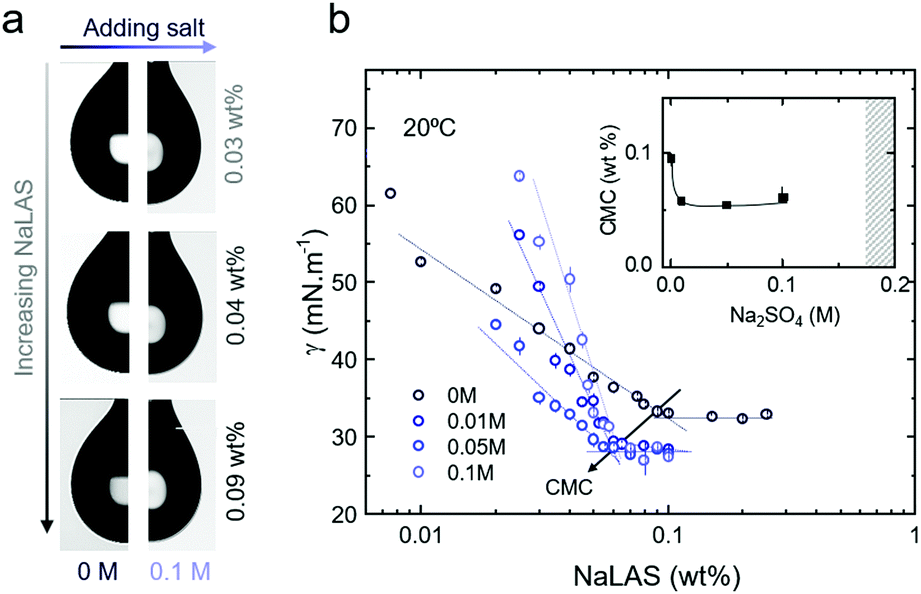 | ||
| Fig. 3 Surface tension measurements of ternary NaLAS/water/Na2SO4 as a function of NaLAS concentration at room temperature. (a) Images of pendant drops of binary NaLAS/water (left) and ternary NaLAS/water/Na2SO4 (right) at different concentrations of NaLAS. Droplets are more elongated at higher surfactant concentration and added electrolyte due to the lower γ. (b) Surface tension of NaLAS solutions with and without added salt. The inset shows the evolution of CMC with increasing Na2SO4 concentration; the shaded area indicates salt concentrations tested where precipitation occurred. | ||
The presence of Na2SO4 was found to reduce the CMC of NaLAS solutions, with the addition of 0.01 M salt yielding a CMC of 0.059 wt%, with no noticeable further change at higher salt (0.05 and 0.1 M), as shown in Fig. 3a and b. At even higher salt concentrations (>0.175 M Na2SO4), the solution was no longer homogeneous and the shaded region in the inset of Fig. 3b corresponds to where precipitation was observed optically (whose origin is discussed below). The value of γ also decreased, in general, with the presence of salt, with some scatter and deviations discussed above.
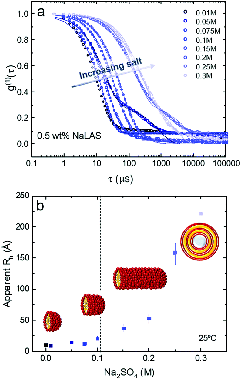 | ||
| Fig. 4 Dynamic light scattering measurements of 0.5 wt% NaLAS solution with added electrolyte. (a) Experimental DLS data for 0.5 wt% aqueous NaLAS in compositions of increasing Na2SO4 concentrations ranging from 0.01 M to 0.3 M with fitted data superimposed. Upon the addition of salt, the curves systematically move towards the right side of the graph are associated with larger time scales. (b) Apparent hydrodynamic radius Rh as a function of Na2SO4 concentration. | ||
A single exponential function can generally describe the time-dependent correlation data corresponding to the main population, with the exception of very low (0.01 M) and high salt concentrations (>0.2 M) where, respectively, data noise is greater or polydispersity is significant. Estimations of the apparent hydrodynamic radius Rh (since non-spherical micelles and vesicles can be expected) as a function of salt concentration are presented in Fig. 4b. Three regimes can be approximately identified, at fixed NaLAS concentration (0.5 wt% shown here): (i) for salt concentrations below 0.1 M, the estimated Rh increases slightly with added salt; (ii) for salt concentrations in the range of 0.1 M ≤ [Na2SO4] ≤ 0.2 M, Rh increases more steeply, while remaining <100 Å, and the solutions are optically clear; (iii) above 0.2 M of salt, Rh significantly increases to reach values of ∼200 Å and above, and a broad distribution of sizes is expected to exist; secondary DLS time decays appear (Fig. 4b) and then optically visible precipitation occurs in the solutions. Comparison of the current DLS findings and structural transformations reported in similar systems,57–59 suggests that NaLAS micelles first elongate to form cylindrical structures before yielding larger assemblies such as multilamellar vesicles, previously reported for NaLAS solutions under other thermodynamic conditions23 or external flow fields.22 These postulated structures are illustrated in Fig. 4b, and are further examined by SANS in the following.
A concentration range of 0 M to 0.35 M Na2SO4 at fixed NaLAS concentration (here, 0.5 wt%) was investigated by SANS, and measurements started at 40 °C where all solutions are homogeneous and optically clear. Scattering profiles were then also obtained at T = 25 °C and T = 15 °C to investigate the effect of cooling. Selected SANS data acquired at these three temperatures at different salt concentrations are presented in Fig. 5. Three distinct features can be observed in the SANS data upon increasing salt concentration across the different conditions: (i) Binary NaLAS/H2O solutions yield an intermediate-Q peak arising from the electrostatic repulsive interaction of globular micelles. This intra-micellar repulsion appears to be screened at low salt concentration (0.1–0.15 M). (ii) An upturn in the low-Q region appears for the range of 0.1–0.2 M. (iii) The slope of the upturn in the low-Q region increases, while the micellar peak disappears, accompanied by the appearance of a high-Q Bragg peak. These qualitative findings are in general agreement with results of our DLS analyses. SANS data fitting quantitatively characterises the micellar structures and their transformations in these three different regimes.
 | ||
| Fig. 5 SANS data for 0.5 wt% aqueous NaLAS mixed in a range of Na2SO4 concentrations (0 M to 0.35 M) upon cooling from 40 °C (top), 25 °C (middle), and 15 °C (bottom). The power law fits I ∝ Qb to the scattering data in the low-Q range and the appearance of a Bragg peak in high-Q region (dashed square) are analysed in Sections 3.2.3 and 3.2.4, respectively. | ||
 | ||
| Fig. 6 Elongation of NaLAS micelles upon addition of salt as a function of temperature. (a) Experimental SANS data for 0.5 wt% aqueous NaLAS at 25 °C containing different Na2SO4 concentrations from 0 M to 0.15 M with fitted data superimposed. Data with peaks in the intermediate-Q region correspond to spherical micelles with radius R, while data with an upturn in the low-Q region are associated with solutions of cylindrical micelles of a similar radius. (b) Micellar length and (c) radius obtained by SANS data analysis. From initially spherical micelles (of similar dimensions with the temperature range investigated), added salt above ∼0.05 M, causes cylindrical micelles to form, whose length increases with Na2SO4 concentration, in a more pronounced manner at the lower temperatures. Scattering data at higher salt concentrations, within the MLV regime, are not included here. | ||
Adding salt in excess of 0.05 M salt to solutions of 0.5 wt% NaLAS, leads to a significant change in the form factor of the micelles. A power law fitted to the low-Q region indicates the formation of elongated micelles. Solutions of 0.1–0.15 M salt, were fitted using core–shell cylinder form factor. While the cylinder radius remains largely unchanged at around 20 Å, the length increases significantly at higher concentration of salt. A similar trend is observed at different temperatures where the transition from spherical micelles to cylinders occurs at lower salt concentration with decreasing temperature, see Fig. 6b. In this range, addition of salt to aqueous micellar solutions of NaLAS slightly modifies the SLD of the micellar shell and solvent as described quantitatively in the ESI,† Fig. S6.
Above a certain salt concentration, the slope in the low-Q region of SANS profiles significantly increases and cylindrical models can no longer describe the form factor. In this region, the sharp Bragg peak in the high-Q region indicates the formation of a multi-layer structure, likely attributed to the formation of multilamellar vesicles MLVs. While the transition from cylindrical to lamellar structures is found at all temperature investigated, the appearance of MLVs is observed at lower salt concentrations upon decreasing temperature, indicated by the vertical markers in Fig. 6b. Note that 0.3 M Na2SO4/NaLAS/H2O solution at 40 °C contains cylinders that are longer than the measurement range accessible with the SANS diffractometer in this configuration  . Conversely, higher temperatures require a higher Na2SO4 concentration to trigger the phase change.
In general, the salt concentrations yielding the onset of transition from spherical to cylindrical, and cylindrical to MLVs, are in good agreement with of DLS measurements that suggested three distinct size ranges with added salt (Fig. 4b).
Upon sufficient salt addition (to a temperature-dependent threshold, see ESI,† Fig. S10), the headgroup repulsion between NaLAS monomers can be interpreted as sufficiently screened to enable closer packing60,61 and greater counter-ion binding, often rationalised in terms of an increase in critical packing parameter (CPP) due to a ‘reduction’ in headgroup area. Overall these changes facilitate the adoption of a lamellar structure,55,63 at specific salt-temperature conditions.
3.3 A temperature-salt morphology map
Previous studies have shown that analysis of the low-Q upturn can readily report on the structural characteristics of the solution.64–66 Here, a I ∝ Qb power law was fitted to the low-Q region to extract the relatively large-scale structural features of the solution. At all temperatures tested here, the b exponent systematically changes with increasing Na2SO4 concentration as shown in Fig. 7a: (i) at low salt concentrations, positive or zero b-values were obtained which are characteristic of spherical or ellipsoidal (globular) micelles. As the salt concentration increases b decreases indicating a structural transformation, (ii) first to b ≈ −1, characteristic of a rod-like micelles, and then to (iii) an exponent closer to −3 to −4, indicative of aggregate behaviour or compact assemblies, such as vesicles. Stage (iii) is accompanied by the appearance of a Bragg peak in the high-Q region, associated with the lamellar d-spacing. | ||
| Fig. 7 Structural transformations in ternary NaLAS/Na2SO4/water solutions at low surfactant concentrations (here 0.5 wt%). (a) A power law, I ∝ Qb was fitted to the SANS data in the low-Q range, and the b exponent is plotted as a function of Na2SO4 and employed as a facile means to classify the phase transformations from spherical/ellipsoidal to cylindrical micelles, to MLVs. Positive b-values arise from the structure factor contribution and are attributed to the electrostatic micellar repulsion, while negative values arise from the dominant form factor contribution. As the salt concentration increases the b-values change to −1 reflecting a cylindrical shape, eventually approaching b ≈ −4 which is indicative of compact MLVs. (b) The Na2SO4 concentrations at which the shape transitions occur changes with temperature. At higher temperatures a more concentrated solution of salt is required. (c) Cryo-TEM images of 0.5 wt% NaLAS in 0.2 M Na2SO4 solution at 25 °C show the presence of micelles (top), cylindrical micelles (middle), and MLVs (bottom). | ||
Fig. 7b describes the coupled effects of temperature and salt addition on the various structural transformations reported here. The addition of relatively small amounts of salt, screens the surfactant head-group repulsions and thus facilitates micellar packing and growth. As a general trend, as the temperature increases more salt is required to induce both transformations. However, the spherical-to-cylindrical transformation has only a slight positive temperature dependence, while the cylindrical-to-MLV transformation exhibits a stronger, linear dependence within the temperature range investigated. We associated this observation with an increase in solubility and additional thermal energy which disrupt ordering processes such as MLV formation.
In order to visualise the different NaLAS aggregates in real space, we employ cryo-TEM and the images corroborate our DLS and SANS findings, see Fig. 7c (images with larger field of view are provided in ESI,† Fig. S12). Note that the small sampling volume, deposition on an external surface and the blotting procedure followed in our TEM analyses may lead to local variations of concentration and disturbance of structures due to inevitable mechanical stress. Therefore, TEM images are mainly provided as qualitative complementary data alongside the equilibrium bulk measurements obtained using DLS and SANS.
Several pathways for MLV formation from micelles have been proposed, including the formation of two-dimensional uni- or multi-layered disks from micelles, which then close and form vesicles upon reaching a maximum radius,67–70 or the elongation of micelles to yield elongated, worm-like objects which coalesce and eventually create vesicles.71,72 Our combined SANS and cryo-TEM measurements show that MLVs in NaLAS/Na2SO4/water are generated through the latter mechanism, supported by evidence of micelle-to-cylinder, followed by cylinder-to-vesicle transformations.
4 Conclusions
NaLAS is one of the most widely used anionic surfactants in the world, in particular in laundry detergents, due to it biodegradable nature. Here, we have examined the solution phase behaviour of aqueous NaLAS as a function of: (i) surfactant concentration (ii) added salt, and (iii) temperature, within a range commonly found in practical applications, for instance in the context of detergents upon dilution, with varying temperature and water hardness. The parameter space investigated is relevant for the practical use of typical fabric liquid detergents and surface cleaners, with ramifications for cleaning efficiency, stability and optical appearance. We employed SANS to characterise the dependence of micellar structures and phase transformations across the parameter space, supported by pendant drop, DLS, cryo-TEM and optical measurements.For NaLAS aqueous solutions, we observe spherical micelles with a radius of ≈20 Å at low surfactant concentrations (≤2.5 wt%), beyond which the equatorial radius increases upon further NaLAS addition, resulting in ellipsoids with aspect ratio up to 3. Elongation is found to increase slightly (∼10–15%) with decreasing temperature, from 25 to 5 °C. As expected, the presence of salt (Na2SO4) decreases the CMC of the surfactant solution, from ≃0.095 wt% for NaLAS aqueous solution, to ≃0.06 wt% which is nearly independent of salt content within 0.01–0.1 M; even higher salt concentrations cause precipitation of the solution. Alongside, the value of the surface tension at CMC drops from γCMC ≈ 33 to 28 mN m−1 upon salt addition.
Employing DLS, we find that the apparent hydrodynamic radius of NaLAS micelles increases pronouncedly with Na2SO4, suggesting the existence of micelle shape transformation at threshold salt concentrations, at a fixed temperature. Analysis of SANS data enables us to resolve three regimes in the solution structure, namely (a) near-spherical micelles, (b) formation of cylindrical micelles and (c) MLV formation, upon increasing salt content. The identification of micellar structures can be readily performed with SANS, from their characteristic low-Q power law exponents, as well as from the emergence of a lamellar peak upon MLV formation. The threshold salt concentration required to induce the transformation from spherical micelles to cylinders is found to be largely independent of temperature, at fixed surfactant concentration. The formation of MLVs, however, depends strongly on temperature, and lower salt concentrations are needed to promote cylinder-to-MLV transformation at lower temperatures, within the 15–40 °C range investigated. Cryo-TEM measurements corroborate our findings and provide real space insight into the overall solution structure, MLV size and polydispersity.
The average d-spacing of MLVs is estimated at 3.3 ± 0.3 nm, consistent with previously published data,23,62 and varies relatively little with salt content and temperature, within measurement uncertainty. Above a sufficiently high salt content (e.g., >0.2 M at 25 °C) surfactant precipitation takes place. As with the previous transformations, with increasing temperature, a higher salt content is required to induce precipitation.
In simple terms, aqueous NaLAS micellar solutions comprise spherical micelles or ellipsoids, upon increasing concentration. The addition of relatively small amounts of salt, screens the inter- and intra-micellar repulsion, thus facilitating packing and causing micelles to grow, first into cylinders (∼0.1 M salt) and eventually into multilamellar vesicles, MLVs (∼0.25 M). The salt threshold concentrations required to induce such changes increases with temperature, as added thermal energy disrupts these ordering processes. Overall, our study provides a comprehensive map and quantification of the micellar structure and transformations in solutions of NaLAS, a ubiquitous anionic surfactant, considering the coupled effects of surfactant concentration, added salt and temperature.
Conflicts of interest
There are no conflicts to declare.Acknowledgements
We thank Procter & Gamble and the EPSRC-funded Advanced Characterisation of Materials CDT for a PhD scholarship for ASR. JTC acknowledges the Royal Academy of Engineering (UK) for a Research chair. We thank Robert Dalgliesh (ISIS) and Lionel Porcar (ILL) for assistance during SANS experiments and Paul A Simpson for help with cryo-TEM measurements. Experiments at the ISIS Neutron and Muon Source were supported by a beamtime allocation RB182037473 from the Science and Technology Facilities Council. This work benefited from the use of the SasView application, originally developed under NSF Award DMR-0520547. SasView also contains code developed with funding from the EU Horizon 2020 Programme under the SINE2020 Project Grant No. 654000.Notes and references
- G. J. Tiddy and A. Khan, Curr. Opin. Colloid Interface Sci., 1999, 6, 379–380 CrossRef.
- J. Falbe, Surfactants in consumer products, Springer, 1987 Search PubMed.
- C. K. Ahn, Y. M. Kim, S. H. Woo and J. M. Park, J. Hazard. Mater., 2008, 154, 153–160 CrossRef CAS PubMed.
- J. J. Sheng, Petroleum, 2015, 1, 97–105 CrossRef.
- I. Kralova and J. Sjöblom, J. Dispersion Sci. Technol., 2009, 30, 1363–1383 CrossRef CAS.
- D. Myers, Surfactant Science and Technology, Wiley, 2005 Search PubMed.
- M. J. Castro, C. Ojeda and A. F. Cirelli, Green Materials for Energy, Products and Depollution, Springer, 2013, pp. 287–334 Search PubMed.
- S. Jain and F. S. Bates, Science, 2003, 300, 460–464 CrossRef CAS PubMed.
- R. G. Laughlin, The aqueous phase behavior of surfactants, Academic Press, 1996 Search PubMed.
- B. Kronberg and B. Lindman, Surfactants and polymers in aqueous solution, John Wiley & Sons Ltd, Chichester, 2003 Search PubMed.
- T. F. Tadros, Applied surfactants: principles and applications, John Wiley & Sons, 2006 Search PubMed.
- B. Lindman and H. Wennerström, Micelles, Springer, 1980, pp. 1–83 Search PubMed.
- C. Tanford, J. Phys. Chem., 1972, 76, 3020–3024 CrossRef CAS.
- H. Wennerstrom and B. Lindman, Phys. Rep., 1979, 52, 1–86 CrossRef.
- L. Maibaum, A. R. Dinner and D. Chandler, J. Phys. Chem. B, 2004, 108, 6778–6781 CrossRef CAS.
- T. Shikata, H. Hirata and T. Kotaka, Langmuir, 1987, 3, 1081–1086 CrossRef CAS.
- J. G. Weers, J. F. Rathman and D. R. Scheuing, Colloid Polym. Sci., 1990, 268, 832–846 CrossRef CAS.
- P. Kamranfar and M. Jamialahmadi, J. Mol. Liq., 2014, 198, 286–291 CrossRef CAS.
- I. Johansson and P. Somasundaran, Handbook for cleaning/decontamination of surfaces, Elsevier, 2007 Search PubMed.
- C. Richards, G. J. T. Tiddy and S. Casey, Langmuir, 2007, 23, 467–474 CrossRef CAS PubMed.
- J. A. Stewart, A. Saiani, A. Bayly and G. J. T. Tiddy, Colloids Surf., A, 2009, 338, 155–161 CrossRef CAS.
- A. S. Poulos, M. Nania, P. Lapham, R. M. Miller, A. J. Smith, H. Tantawy, J. Caragay, J. Gummel, O. Ces, E. S. J. Robles and J. T. Cabral, Langmuir, 2016, 32, 5852–5861 CrossRef CAS PubMed.
- S. Khodaparast, W. Sharratt, H. Wang, E. S. Robles, R. Dalgliesh and J. T. Cabral, J. Colloid Interface Sci., 2019, 546, 221–230 CrossRef CAS PubMed.
- H. Wang, S. Khodaparast, J. Carroll, C. Kelly, E. S. J. Robles and J. T. Cabral, Rev. Sci. Instrum., 2020, 91, 045109 CrossRef PubMed.
- D. Bendedouch, S. H. Chen and W. C. Koehler, J. Phys. Chem., 1983, 87, 153–159 CrossRef CAS.
- V. Y. Bezzobotnov, S. Borbely, L. Cser, B. Farago, I. A. Gladkih, Y. M. Ostanevich and S. Vass, J. Phys. Chem., 1988, 92, 5738–5743 CrossRef CAS.
- J. Gao, W. Ge and J. Li, Sci. China, Ser. B: Chem., 2005, 48, 470–475 CrossRef CAS.
- B. Hammouda, J. Res. Natl. Inst. Stand. Technol., 2013, 118, 151–167 CrossRef CAS PubMed.
- J. N. Israelachvili, Intermolecular and surface forces, Academic Press, 2015 Search PubMed.
- M. L. Corrin and W. D. Harkins, J. Am. Chem. Soc., 1947, 69, 683–688 CrossRef CAS PubMed.
- H. B. Klevens, J. Phys. Colloid Chem., 1948, 52, 130–148 CrossRef CAS PubMed.
- P. Becher, J. Colloid Sci., 1962, 17, 325–333 CrossRef CAS.
- S. Woolfrey, G. Banzon and M. Groves, J. Colloid Interface Sci., 1986, 112, 583–587 CrossRef CAS.
- S. S. Datwani and K. J. Stebe, Langmuir, 2001, 17, 4287–4296 CrossRef CAS.
- M. Corrin and W. D. Harkins, J. Am. Chem. Soc., 1947, 69, 683–688 CrossRef CAS PubMed.
- C. Tanford, The hydrophobic effect: formation of micelles and biological membranes, J. Wiley, 2nd edn, 1980 Search PubMed.
- S. S. Berr and R. R. M. Jones, Langmuir, 1988, 4, 1247–1251 CrossRef CAS.
- P. Debye and E. W. Anacker, J. Phys. Chem., 1951, 55, 644–655 CrossRef CAS PubMed.
- M. Almgren, J. Gimel, K. Wang, G. Karlsson, K. Edwards, W. Brown and K. Mortensen, J. Colloid Interface Sci., 1998, 202, 222–231 CrossRef CAS.
- L. Cohen, A. Moreno and J. L. Berna, J. Am. Oil Chem. Soc., 1993, 70, 79–82 CrossRef CAS.
- Y. Cao, R.-h. Zhao, L. Zhang, Z.-c. Xu, Z.-q. Jin, L. Luo, L. Zhang and S. Zhao, Energy Fuels, 2012, 26, 2175–2181 CrossRef CAS.
- O. Arnold, J.-C. Bilheux, J. Borreguero, A. Buts, S. I. Campbell, L. Chapon, M. Doucet, N. Draper, R. F. Leal and M. Gigg, et al. , Nucl. Instrum. Methods Phys. Res., Sect. A, 2014, 764, 156–166 CrossRef CAS.
- GRASP, https://www.ill.eu/en/users/support-labs-infrastructure/software-scientific-tools/grasp/, 2003.
- SasView Project, http://www.sasview.org/, 2020.
- J. Hayter and J. Hansen, Mol. Phys., 1982, 46, 651–656 CrossRef.
- J. B. Hayter and J. Penfold, Mol. Phys., 1981, 42, 109–118 CrossRef CAS.
- T. Zemb and P. Charpin, J. Phys., 1985, 46, 249–256 CrossRef CAS.
- S. H. Chen, E. Y. Sheu, J. Kalus and H. Hoffman, J. Appl. Crystallogr., 1988, 21, 751–769 CrossRef CAS.
- V. Aswal and P. Goyal, Chem. Phys. Lett., 2003, 368, 59–65 CrossRef CAS.
- J. Iyer and D. Blankschtein, J. Phys. Chem. B, 2012, 116, 6443–6454 CrossRef CAS PubMed.
- S.-Y. Lin, Y.-Y. Lin, E.-M. Chen, C.-T. Hsu and C.-C. Kwan, Langmuir, 1999, 15, 4370–4376 CrossRef CAS.
- D. L. Smith, J. Am. Oil Chem. Soc., 1997, 74, 837–845 CrossRef CAS.
- Y. Zhu, M. J. Rosen, S. W. Morrall and J. Tolls, J. Surfactants Deterg., 1998, 1, 187–193 CrossRef CAS.
- V. Fainerman, E. Lucassen-Reynders and R. Miller, Colloids Surf., A, 1998, 143, 141–165 CrossRef CAS.
- J.-G. Ma, B. J. Boyd and C. J. Drummond, Langmuir, 2006, 22, 8646–8654 CrossRef CAS PubMed.
- R. Miller and G. Kretzschmar, Adv. Colloid Interface Sci., 1991, 37, 97–121 CrossRef CAS.
- K. D. Danov, P. A. Kralchevsky, S. D. Stoyanov, J. L. Cook, I. P. Stott and E. G. Pelan, Adv. Colloid Interface Sci., 2018, 256, 1–22 CrossRef CAS PubMed.
- D. Lombardo, M. A. Kiselev, S. Magazù and P. Calandra, Adv. Condens. Matter Phys., 2015, 2015, 151683 Search PubMed.
- P. Wang, S. Pei, M. Wang, Y. Yan, X. Sun and J. Zhang, Phys. Chem. Chem. Phys., 2017, 19, 4462–4468 RSC.
- W. Kunz, Curr. Opin. Colloid Interface Sci., 2010, 15, 34–39 CrossRef CAS.
- W. Kunz, P. L. Nostro and B. W. Ninham, Curr. Opin. Colloid Interface Sci., 2004, 9, 1–18 CrossRef CAS.
- J. Stewart, A. Saiani, A. Bayly and G. Tiddy, J. Dispersion Sci. Technol., 2011, 32, 1700–1710 CrossRef CAS.
- A. Sein and J. B. Engberts, Langmuir, 1995, 11, 455–465 CrossRef CAS.
- N. Jouault, R. Nguyen, M. Rawiso, N. Giuseppone and E. Buhler, Soft Matter, 2011, 7, 4787–4800 RSC.
- H. Frielinghaus, Phys. Rev. E: Stat., Nonlinear, Soft Matter Phys., 2007, 76, 051603 CrossRef PubMed.
- J. E. Moore, T. M. McCoy, L. de Campo, A. V. Sokolova, C. J. Garvey, G. Pearson, B. L. Wilkinson and R. F. Tabor, J. Colloid Interface Sci., 2018, 529, 464–475 CrossRef CAS PubMed.
- J. Leng, S. U. Egelhaaf and M. E. Cates, Biophys. J., 2003, 85, 1624–1646 CrossRef CAS PubMed.
- K. Bressel, M. Muthig, S. Prevost, J. Gummel, T. Narayanan and M. Gradzielski, ACS Nano, 2012, 6, 5858–5865 CrossRef CAS PubMed.
- T. M. Weiss, T. Narayanan, C. Wolf, M. Gradzielski, P. Panine, S. Finet and W. I. Helsby, Phys. Rev. Lett., 2005, 94, 038303 CrossRef CAS PubMed.
- C. Huang, D. Quinn, Y. Sadovsky, S. Suresh and K. J. Hsia, Proc. Natl. Acad. Sci. U. S. A., 2017, 114, 2910–2915 CrossRef CAS PubMed.
- M. J. Derry, O. O. Mykhaylyk and S. P. Armes, Angew. Chem., Int. Ed., 2017, 56, 1746–1750 CrossRef CAS PubMed.
- A. Blanazs, J. Madsen, G. Battaglia, A. J. Ryan and S. P. Armes, J. Am. Chem. Soc., 2011, 133, 16581–16587 CrossRef CAS PubMed.
- ISIS Neutron and Muon Source experiments RB1820374, DOI: 10.5286/ISIS.E.RB1820374.
Footnotes |
| † Electronic supplementary information (ESI) available. See DOI: 10.1039/d0sm00982b |
| ‡ Present address: School of Mechanical Engineering, University of Leeds, Leeds LS2 9JT, UK. |
| This journal is © The Royal Society of Chemistry 2020 |