 Open Access Article
Liquid crystal–ferrofluid emulsions
Ingo
Dierking
 *,
Susumu
Yoshida
,
Thomas
Kelly
and
William
Pitcher
Department of Physics and Astronomy, University of Manchester, Oxford Road, Manchester M13 9PL, UK. E-mail: ingo.dierking@manchester.ac.uk
First published on 15th June 2020
Abstract
Despite the development of the brilliant flat-panel TVs and computer screens that we all use on a daily basis, liquid crystals are far from being exhausted as a topic of research. Novel effects, new, modern, self-organized materials, and a range of applications are being developed, which are on the borderline between nanotechnology and soft condensed matter, and which use liquid crystals as a vehicle to study fundamental physical questions, all the way to mimicking nature and life. In this perspective article we will introduce an illustrative example, which will draw on a range of non-display aspects in liquid crystal research which have increasingly gained interest over the past years, namely self-organization of liquid crystals, colloidal ordering of magnetic nanoparticles, topological defects, and biological structures.
1. Introduction
Liquid crystals1–4 are partially ordered, anisotropic fluids which are thermodynamically located between the three-dimensional lattice of a solid crystal and the flow-governed isotropic liquid state (Fig. 1(A)). Mesogenic molecules exhibit orientational and/or low-dimensional positional order of their long molecular axes or the molecular centres of mass, respectively. This results in anisotropic physical properties, such as birefringence, viscosity, elasticity, electrical conductivity, or magnetic susceptibility, all while retaining the ability for flow. Two general classes of liquid crystals are mostly distinguished: thermotropic materials,5,6 which exhibit the liquid crystalline state exclusively on temperature variation, and lyotropic liquid crystals,7 where the formation of liquid crystal phases is achieved by concentration variation of shape anisotropic dopant materials in an isotropic carrier or host fluid. The latter type is most often composed from amphiphilic molecules in water, but can also be observed by dispersing anisotropic colloidal particles in an isotropic liquid.8 This had already been reported by Freundlich9 in 1915 for vanadium pentoxide, V2O5, but is also observed for other minerals and clays, leading to inorganic liquid crystals.10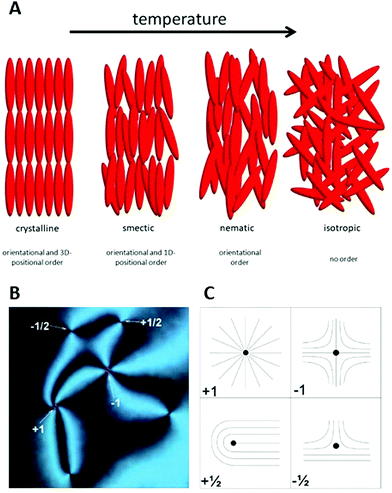 | ||
| Fig. 1 (A) Sequence and schematic structure of phases observed for calamitic, thermotropic molecules. On heating a three-dimensional crystal loses parts of its order and forms lower dimensional smectic phases, which evolve into the nematic phase with purely orientational order. Eventually, at higher temperatures, the formation of a normal isotropic liquid is observed. (B) In polarizing microscopy (POM), the nematic phase can exhibit topological defects of different sign and strength. The corresponding director field is shown schematically in part (c). (Reproduced by permission from ref. 11). | ||
Liquid crystal–nanoparticle dispersions
More recently, thermotropic dispersions and lyotropic liquid crystalline behaviour have also been reported for carbon based materials, such as nanotubes12–17 for templates and addressable molecular switches, and graphene oxide18–23 for possible displays based on the Kerr effect. Further reports discuss inorganic nanorods,24–28 ferroelectric particles,29–31 magnetic nanorods32,33 and platelets for ferromagnetic nematics, but also the incorporation of fullerenes34,35 or gold nanoparticles36–38 into liquid crystal phases or directly into mesogenic molecules for plasmonics. The general reasons for dispersing colloids in liquid crystals by one way or another,39,40 are threefold: (i) to tune the liquid crystal properties, (ii) to add functionality such as ferroelectricity, semiconductivity, plasmonic activity or magnetism to a material which is easily capable of being re-oriented by external stimuli, or (iii) to exploit the self-organization of the liquid crystal and use it as a template to transfer order onto dispersed nanomaterials.Topological defects
One of the characteristics of all liquid crystals is their extremely small elastic constants as compared to solid state materials. This in turn implies that while in the solid state, defects extend over dimension of several atoms, topological defects in liquid crystals extend over distances of tens of micrometres, so that they can easily be observed in standard polarizing microscopy (POM). This leads to a Schlieren texture, examples of which are shown in Fig. 1(B), with topological defects of strength s = ±1/2 (two-fold brushes) and s = ±1 (four-fold brushes). Defects of opposite sign and equal strength attract each other and annihilate.41–43 The schematic director configurations are shown in Fig. 1(C). In the classic work of Muševič et al.44,45 it has been shown experimentally that such defects can also be induced when micro-spheres are dispersed in a nematic liquid crystal, where hedgehog and Saturn ring defects can be observed for different anchoring conditions of the mesogens on the micro-spheres, as shown in Fig. 2. The attraction between defects can also lead to the phenomenon of chaining, where linear chains of colloids are formed for dipolar interactions, while quadrupolar interactions lead to zigzag-shaped chains. This can also be observed for rod-shaped colloidal particles.45–47 The dipolar case was already observed in the pioneering work of Poulin et al.,48 who investigated nematic-water emulsions with water droplets acting as colloidal particles (Fig. 3). They were also the first to briefly employ ferrofluid droplets as a means to measure the colloidal force that attracts two droplet colloids.49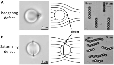 | ||
| Fig. 2 Defects observed in the vicinity of microspheres, dispersed in a nematic liquid crystal. (A) Microscopic image of a hedgehog defect, together with the schematic director configuration. The interaction between colloids which give rise to hedgehog defects is of dipolar nature and leads to linear chaining. (B) Saturn ring defects lead to quadrupolar interactions between colloids and give rise to zigzag chaining. [Images are reproduced by permission from ref. 45]. | ||
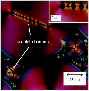 | ||
| Fig. 3 Polarizing micrograph of a texture of a water in liquid crystal-in-water emulsion, exhibiting chains of water droplets. [Reproduced by permission after ref. 48]. | ||
‘Anisotropic ferrofluids’ and real ferronematics
The dispersion of ferromagnetic particles in nematic liquid crystals had already been discussed by Brochard and deGennes,50 introducing such systems under the slightly misleading terms of ‘ferronematics’. When dispersing magnetic particles in a liquid crystal,51–54 different scenarios need to be distinguished, which collectively are often referred to in literature as ‘ferronematic’ or ‘ferromagnetic nematics’. A simple dispersion of magnetic particles in a nematic phase does in most cases not result in a ferromagnetic system, but rather in a paramagnetic one. The magnetisation vectors of individual particles will align in an applied magnetic field, but as soon as this is removed, thermal motion will rapidly drive these back to complete randomness. In analogy to ferroelectricity, a truly ferromagnetic system would require a permanent macroscopic magnetization, M, which remains pointing in the direction of the originally applied field, even after its removal, and which in addition is reversible by reversing the magnetic field direction.55,56 This implies that there will be a net remnant magnetisation at zero field, and the phenomenon of hysteresis is observed. This is generally not the case, and the system of dispersed magnetic particles in liquid crystals rather behaves like a ferrofluid with an anisotropic carrier fluid. The same holds true for a preparation method sometimes used to achieve uniform dispersions by mixing a nematic with a ferrofluid, and then evaporating the isotropic solvent. Nevertheless, this should not distract from the fact that these are interesting systems and materials in their own right, for example in the study of magnetic pattern formation.57In the prediction of the systems proposed by Brochard and deGennes,50 ferronematics would form by dispersing rod-like magnetic particles in a nematic liquid crystal—a dispersion which has even to date not been shown to exhibit ferromagnetic properties. This is due to the fact that if the ferromagnetic coupling would be strong enough to exhibit a macroscopic magnetisation, particles would aggregate and the uniformity of the dispersion would be lost. The first real ferronematics were only recently reported by Mertelj et al.58,59 for plate-like magnetic nanoparticles with a homeotropic surface coating (Fig. 4). The system is characterised by two order parameters, that of the director, n, and that of the magnetisation, M. The director order parameter is non-polar, while the magnetisation order parameter is polar. The surface anchoring conditions on the magnetic nano-plates lead to a coupling of both order parameters. These first true ferronematics and their magneto- and electro-optic properties have recently been reviewed by Mertelj and Lisjak.60
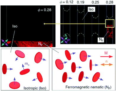 | ||
| Fig. 4 Ferronematic of surface coated magnetic nanoplates dispersed in a nematic liquid crystal. A spontaneously ordered magnetisation M along the director is observed at a volume fraction of Φ = 0.28. [Reproduced by permission after ref. 59]. | ||
The approach to generate yet a different class of materials is to increase the complexity of the above outlined dispersions of solid magnetic particles within a liquid crystal host, to emulsions where the magnetic solid particles are dispersed in an isotropic solvent, which in turn is dispersed in the liquid crystal host. Such LC-ferrofluid emulsions have only been studied very rarely,49,61–63 where in some cases the isotropic solvent has been deliberately evaporated, leading to nothing more than the above outlined particle dispersions. In contrast, it is suggested to combine all the aspects discussed above: the self-organisation of the liquid crystal with the dispersion of magnetic nanoparticles in a carrier fluid, together with phase separation as a key ingredient. This leads to micro-droplets of ferrofluids, generating topological defects which may also induce chaining.
2. Liquid crystal–ferrofluid emulsions
Model and isotropic liquids
We thus disperse functional, in this case magnetic, anisotropic nanoparticles in an isotropic liquid carrier fluid, which was then in turn dispersed in an anisotropic liquid crystal. We investigated ferrofluid droplets in an anisotropic liquid and through application of external magnetic fields developed a method to experimentally determine the viscosities of the liquid crystal, their temperature dependence, and their anisotropy on a microscopic scale. Further possibilities to exploit the properties of these emulsions will be discussed in the outlook section below. At first the proposed methodology needs to be verified against different liquids with a wide range of well-known viscosity values, for example water, glycerine and silicon oil. The carrier fluids for the ferrofluid were chosen so that the magnetic droplets were immiscible with the surrounding liquid, in this case water-based WHKS1S12 (Liquid Research Ltd, UK) in glycerine, silicon oil and further also in the nematic liquid crystal 5CB, and the oil-based ferrofluid EFH1 (Ferrotech, USA) in water. Micrometer sized droplets were formed at varying diameters. Bringing a permanent magnet close to the ferrofluid micro-droplets causes them to quickly reach a steady motion (Fig. 5).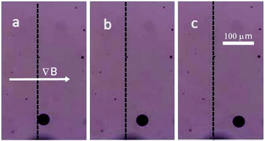 | ||
| Fig. 5 A micro-droplet of ferrofluid WHKS1S12 in glycerine quickly reaches a steady state velocity in a magnetic field gradient, ∇B, shown at (a) t = 0 s, (b) t = 5 s and (c) t = 10 s. | ||
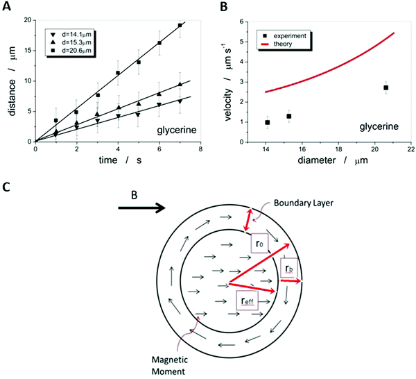
The droplet position can be determined as a function of time, which results in a linear relationship, and thus a constant velocity can be determined, which depends on the droplet size (Fig. 6(A)).
This situation is similar to the classic Stokes’ experiment for determining the viscosity of a fluid through measurement of the velocity of a steel ball due to the gravitational force. It should be noted though that the classic Stokes model of balancing the magnetic force and the viscous drag force is the simplest model available and is strictly speaking only valid for a solid sphere with non-slip boundary conditions in the limit of very small Reynolds numbers, RE = ρveqr/γ ≪ 1, where ρ is the density, veq the terminal velocity, r the radius of the solid sphere and γ the viscosity. For the experimental conditions the last constraint is fulfilled, but we are not dealing with a solid body and do not know about the boundary conditions. So, this only is the simplest model of what could be a rather complicated problem. In analogy, under application of a magnetic field gradient, the ferrofluid droplet reaches an equilibrium speed, veq when the magnetic force Fm balances the viscous force Fs, i.e. when Fm = Fs or:
| Vμ0Mm·∇H = 6πγrveq | (1) |
 | (2) |
In a similar manner, the viscosities of water and silicon oil were determined from the steady state motion of ferrofluid droplets of varying size, as depicted in Fig. 7(A) for EFH1 in water at |∇B| = 1.74 T m−1 and WHKS1S12 in silicon oil at |∇B| = 12.6 T m−1 (Fig. 7(B)).
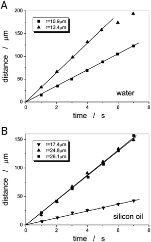 | ||
| Fig. 7 Linear ferrofluid micro-droplet displacement as a function of time for (A) water at |∇B| = 1.74 T m−1 and (B) silicon oil at |∇B| = 12.6 T m−1. | ||
Table 1 provides a summary of the results obtained for the different liquids investigated, which cover a viscosity range of three orders of magnitude.
Thermotropic nematic liquid crystal
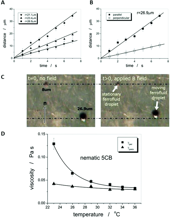
As the microscopic viscosities of water, silicon oil and glycerine, varying by a factor of 103 in magnitude, could all be obtained within very reasonable limits to their literature values, one can be confident to apply the method to an anisotropic liquid crystal, namely the standard 5CB, which is commercially available (Synthon Chemicals, Germany). But again a word of caution. The situation is in principle made much more complex in an anisotropic environment, such as a nematic liquid crystal as the carrier liquid, as discussed in detail by Stark and Ventzki.67 In this case the Ericksen number ER = ρveqr/K, with K being the elastic constant in the single constant approximation, should also be ER ≪ 1 so that the viscous forces are too weak to distort the liquid crystal. For normal experimental conditions (ρ ≈ 1 g cm−3, veq ≈ 10 μm s−1, r ≈ 10 μm and K ≈ 7 × 10⁻¹² N) this is not necessarily the case and it is merely ER < 1. This may have an effect on the measured viscosity values through neglecting nonlinear and correction terms. Nevertheless, we believe these to be relatively small and within the experimental errors of approximately ±10%.Also for the nematic liquid crystal 5CB as dispersion fluid different droplet velocities veq are observed for different sizes of droplets, as indicated by the distance vs. time measurements of Fig. 8(A). A boundary layer thickness rb = (4.4 ± 0.2) μm was determined which corresponds very well with the observation that ferrofluid droplets with a diameter of d < 2rb ∼ 8 μm, were stationary, as shown in Fig. 8(C). To determine the anisotropic viscosities γ‖ and γ⊥, parallel and perpendicular to the director, n, the ferrofluid droplet simply has to be moved in the two corresponding directions. Different velocities in these directions are clearly exhibited, as depicted in Fig. 8(B), and one obtains values of γ‖ = 42 mPa s and γ⊥ = 129 mPa s at room temperature, which are in excellent agreement with values reported in literature68 at 25 °C (γ‖ = 44 mPa s and γ⊥ = 120 mPa s). The temperature dependence of the viscosity anisotropy, γ(T), of 5CB is shown in Fig. 8(D), which again is very similar to that of literature.68
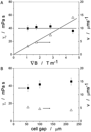
Varying the magnetic field gradient, it is found that the ferrofluid droplet velocity increases practically linearly with the applied gradient, as expected (Fig. 9(A) open triangles) for a constant droplet diameter. The magnetic field gradient on the other hand would not be expected to have any influence on the actual viscosity of the liquid crystal, which is demonstrated by the data of the closed squares in Fig. 9(A), where γ‖ is constant at a value of approximately 40 mPa s as expected from previous measurements and in accordance with literature values at room temperature. The confinement does not have a significant influence on the values of either droplet velocity or measured liquid crystal viscosity, as depicted in Fig. 9(B) for a constant magnetic field gradient of 1.75 T m−1. Again, values of the order γ‖ = 40 mPa s are obtained for the viscosity along the director.
We have thus demonstrated a microscopic technique to determine the viscosities of liquid crystals. In contrast to traditional methods, this provides the advantage of being experimentally simple, quick and above all, it requires much less material, only about 1/1000 of the mass of the liquid crystal compared to conventional rheology techniques. This is of significant importance, knowing that liquid crystals are generally synthesised on the scale of milligrams rather than grams.
Ferrofluid droplet chaining and defect interaction
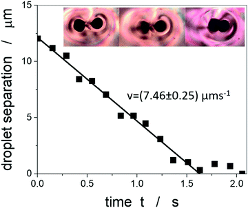
A further phenomenon that can be observed in liquid crystal-ferrofluid emulsions is the chaining of droplets, similar to the water droplet chains observed by Poulin et al.,48 or more generally the chaining of colloidal particles in nematic liquid crystals as reported by Muševič et al.45 and references therein. This is due to the hyperbolic hedgehog defects in the close vicinity of each ferrofluid droplet, which leads to a dipolar director field and an attractive interaction between droplets, causing the formation of linear chains, as depicted in Fig. 10(C).In one of the very few publications related to liquid crystal-ferrofluid emulsions, Poulin et al.49 show that the force between two colloidal droplets of ferrofluids scales as  , where d is the distance between the droplets. We cannot observe this behaviour in our experiments, which may be due to the fact that our droplets are substantially larger than the ones observed by Poulin. What we do find in our experiments for pairs of droplets (Fig. 10(B)) is the so-called bubble-gum defect.49 The application of a magnetic field to a pair of ferrofluid droplets induces magnetic dipoles, which cause the droplets to separate. Turning the magnetic field off, elastic interactions cause an attractive force between the droplets, decreasing their separation with time. It is found, that this decrease is linear with time, indicating a constant attractive force (Fig. 11).
Balancing the attractive force with the Stokes drag while neglecting the inertial force, which is much smaller, allows for the estimation of the force between two ferrofluid droplets. When using our previously determined viscosity of 40 mPa s we obtain the attractive force to approximately F ≈ 3.7 × 10⁻¹¹ N, or with an elastic constant of 5CB of K = 7 pN,69 it is F = 5 K. This is comparable to the result obtained by Poulin et al.49 Liquid crystal-ferrofluid emulsions thus also offer the possibility to study directly the forces between micron-sized inclusions in liquid crystals.
3. Outlook
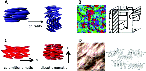
One of the natural continuations of the demonstrated viscosity measuring technique is its application to other liquid crystalline materials and phases, especially as these have not been determined very often, if at all, in contrast to the rotational viscosity γθ for example of smectic C phases, which is of different physical nature. A number of scenarios can be envisioned, the first one being the addition of a small amount of a chiral dopant to a nematic liquid crystal, thus producing a chiral nematic or cholesteric phase (Fig. 12(A)). Performance of the same experiment as above, dragging the ferrofluid droplet into different directions in the plane of the substrate, should in this chiral case result in a direction-independent viscosity with a value between those of γ⊥ and γ‖ of the nematic host. Similarly, the viscosity of blue phases (Fig. 12(B)) should be independent of direction, as these are of cubic symmetry. Differences in viscosity between the amorphous BPIII, the simple cubic BPII and the face-centred cubic BPI should be detectable. One may further compare rod-like with disk-like molecules with respect to their viscosities and viscosity anisotropies, at least in the nematic phase (Fig. 12(C)). Other phases may be too viscous and require magnetic fields that are too large to achieve practically.Similarly, investigations are of course not limited to thermotropic liquid crystals. Using an oil-based ferrofluid instead of a water based one, studies could include various lyotropic liquid crystal phases, chromonics,70,71 inorganic and mineral colloidal liquid crystals72,73 like vanadium pentoxide (V2O5), AlOOH, Li2Mo6Se6, or clays like bentonite, laptonite and imogolite, especially as a function of concentration. Furthermore, liquid crystals from biological colloids such as tobacco mosaic viruses (TMV),74 cellulose nanocrystals,75–77 or DNA78,79 are obviously of interest with respect to their viscosities, especially in relation to concentration and size. But also the carbon based liquid crystals that have been demonstrated from nanotubes16,17 as well as graphene oxide18,19 (Fig. 12(D)), and which are becoming of increasing interest for the orientation and assembly of nanomaterials in nanotechnology applications9—processes where viscosities play an important role.
Recent interest in liquid crystal based materials with dispersed nano- and micro-particles has also arisen in areas that are especially related to non-display technologies and nanotechnology.80 These include nanophotonics, plasmonics, opto-electronics, photovoltaics and sensors, just to name a few. Liquid crystal-ferrofluid emulsions show potential as magnetic field sensors, by being able to determine the runtime of monodisperse ferrofluid droplets in a liquid crystal, as they could be generated via microfluidic devices. Generally, ferrofluids are not conductive, so that they can not be directly determined by closing an electronic switch unless the concentration of metallic particles is large enough to form a percolation network. Nevertheless, the addition of a small amount of salt to the carrier fluid (water) may already overcome this shortcoming. Otherwise, an especially designed conductive ferrofluid81 or a so called smart-fluid82 can be employed.
We are anticipating to combine all the above mentioned materials and effects: liquid crystals, colloids, ferrofluids, topological defects, chaining and biological functionality into one entity, to produce a structure that will mimic magnetotactic bacteria.83–85 Solid magnetic particles are dispersed in an isotropic, carrier fluid, water. The so formed ferrofluid is dispersed as micro-droplets in a thermotropic room temperature nematic liquid crystal. These droplets act as colloidal inclusions and give rise to the formation of topological defects in the director field of the liquid crystal, as shown in Fig. 3. The attractive force between the defects leads to chaining of the ferrofluid droplets, as demonstrated for a three droplet chain in Fig. 13(A). Application of a magnetic field causes the whole chain to move, without destroying it. Emulsions with ferrofluid droplet chains in a liquid crystal can be formed in water by surrounding with a lipid bilayer through the addition of amphiphilic surfactants at concentrations large enough to form vesicles, or by microfluidics with lamellar lyotropic phases (Fig. 13(C)). The result is a microscopic self-organized structure, which mimics a magnetotactic bacterium (Fig. 13(B)) with its chain of magnetosomes surrounded by a bilayer cell membrane. The artificial structure will orient with its chain into the direction of an applied magnetic field gradient, and translate in water along the field lines, just like biological magnetic bacteria do due to Earths' magnetic field. Depending on surface tension conditions, length of the ferrofluid droplet chain and elasticity of the bilayer membrane, the artificial bacteria may be spherical in shape but could also be elongated like real biological magnetotactic bacteria (Fig. 13(C), right).
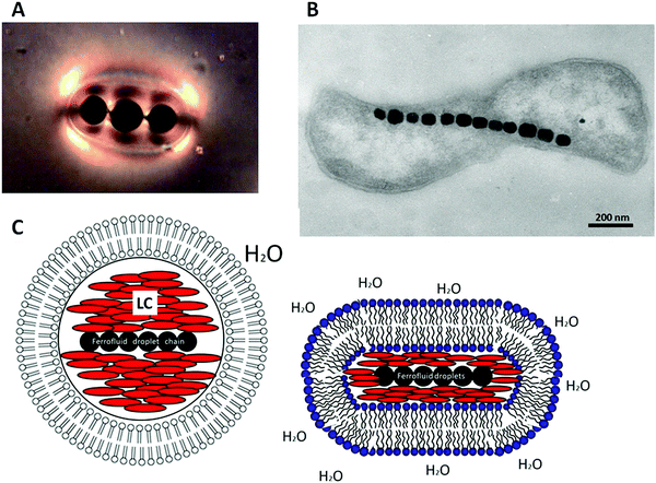 | ||
| Fig. 13 Possible biological applications could be found in the construction of a structure that mimics magnetotactic bacteria. (A) Liquid crystal emulsified ferrofluid droplets act as magnetosomes, inducing defects in the liquid crystal director field, which in turn attract each other to enable the formation of magnetic droplet chains, similar to a magnetotactic bacterium (B) [reproduced by permission from ref. 85]. (C) The liquid crystal drop containing the magnetic chain can be dispersed in water and coated with a lipid bilayer either by addition of a suitable amphiphilic material or by microfluidics with lyotropic lamellar liquid crystal vesicles. | ||
4. Conclusions
Besides the commercial success of liquid crystals in displays and flat-screen applications, a whole new field of liquid crystal based composites has attracted much increasing interest over recent years. These are namely a large variety of liquid crystal-nanoparticle dispersions, which use a plethora of different materials, such as nanotubes, fullerenes, ferroelectric nanomaterials, magnetic spheres and discs, quantum dots, or gold nanoparticles, just to name a few. These are mainly used in nematic liquid crystals to modify its properties, add functionalities, or to exploit the liquid crystalline self-organisation for material structuring in nanotechnology. Resulting from these investigations a wealth of fundamentally novel physics, as well as potential applications, has emerged. Most of these studies employ solid particles of various sizes, shapes and properties being dispersed in either a liquid crystal or a suitable isotropic liquid to form lyotropic liquid crystalline systems. Here, we point out some perspectives that open up when going down the somewhat different route of liquid crystal-ferrofluid emulsions, systems of solid particles in isotropic liquids, which in turn are phase separated from a liquid crystal matrix. It was demonstrated that such materials allow the microscopic determination of viscosities, their anisotropy, and the temperature dependence for a huge number of different anisotropic fluids. They also present interesting systems for the study of defect director fields, the formation of chains, and allow the direct measurement of interactions between micro-scale colloids. We have outlined perspectives for future investigations in viscosity determination of yet only rarely studied systems like frustrated liquid crystals, discotics, chromonics, lyotropic graphene oxide or inorganic liquid crystals. Furthermore biological liquid crystals can be studied, including virus formed phases, DNA or cellulose and cellulose nanocrystals. A fascinating field that is opened by ferrofluid inclusions is their exploitation through chaining via defects as building blocks of artificial magnetotactic bacteria.It can thus be concluded that besides the well-known applications of liquid crystals in electro-optic devices and displays, telecommunication, or photonics, the addition of various colloidal particles opens a whole new field to use liquid crystals as a vehicle for fundamental physics investigations and novel materials design and applications. Liquid crystal–ferrofluid emulsions will certainly play their part in the future of this research.
Conflicts of interest
There are no conflicts to declare.References
- P. J. Collings, Liquid Crystals: Nature's Delicate Phase of Matter, Adam Hilger, Bristol, 1990 Search PubMed.
- P. J. Collings and M. Hird, Introduction to Liquid Crystals: Chemistry and Physics, Taylor & Francis, London, 1997 Search PubMed.
- S. Chandrasekhar, Liquid Crystals, Cambridge University Press, Cambridge, 2nd edn, 1992 Search PubMed.
- S. Singh, Liquid Crystals: Fundamentals, World Scientific, Singapore, 2002 Search PubMed.
- P. G. de Gennes and J. Prost, The Physics of Liquid Crystals, Clarendon Press, Oxford, 2nd edn, 1993 Search PubMed.
- I. Dierking, Textures of Liquid Crystals, Wiley-VCH, Weinheim, 2003 Search PubMed.
- A. M. Figueiredo Neto and S. R. A. Salinas, The Physics of Lyotropic Liquid Crystals, Oxford University Press, Oxford, 2005 Search PubMed.
- I. Dierking and S. Al-Zangana, Nanomaterials, 2017, 7, 305 CrossRef PubMed.
- H. Diesselhorst and H. Freundlich, Phys. Z., 1915, 16, 419 CAS.
- A. S. Sonin, J. Mater. Chem., 1998, 8, 2557 RSC.
- I. Dierking and P. Archer, RSC Adv., 2013, 3, 26433 RSC.
- I. Dierking, G. Scalia, P. Morales and D. LeClere, Adv. Mater., 2004, 16, 865 CrossRef CAS.
- I. Dierking, G. Scalia and P. Morales, J. Appl. Phys., 2005, 97, 044309 CrossRef.
- J. Lagerwall, G. Scalia, M. Haluska, U. Dettlaf-Weglikowska, S. Roth and F. Giesselmann, Adv. Mater., 2007, 19, 359 CrossRef CAS.
- S. Kumar and H. K. Bisoyi, Angew. Chem., Int. Ed., 2007, 46, 1501 CrossRef CAS PubMed.
- W. Song, I. A. Kinloch and A. H. Windle, Science, 2003, 302, 1363 CrossRef CAS PubMed.
- S. Badaire, C. Zakri, M. Maugey, A. Derre, J. N. Barisci, G. Wallace and O. Poulin, Adv. Mater., 2005, 13, 1673 CrossRef.
- J. E. Kim, T. H. Han, S. H. Lee, J. Y. Kim, C. W. Ahn, J. M. Yun and S. O. Kim, Angew. Chem., Int. Ed., 2011, 50, 3043 CrossRef CAS PubMed.
- Z. Xu and C. Gao, ACS Nano, 2011, 5, 2908 CrossRef CAS PubMed.
- T. Z. Shen, S. H. Hong and J. K. Song, Nat. Mater., 2014, 13, 394 CrossRef CAS PubMed.
- S. Al-Zangana, M. Iliut, M. Turner, A. Vijayaraghavan and I. Dierking, Adv. Opt. Mater., 2016, 4, 1541 CrossRef CAS.
- S. Al-Zangana, M. Iliut, M. Turner, A. Vijayaraghavan and I. Dierking, 2D Mater., 2017, 4, 041004 CrossRef.
- R. Narayan, J. E. Kim, J. Y. Kim, K. E. Lee and S. O. Kim, Adv. Mater., 2016, 28, 3044 CrossRef CAS PubMed.
- S. Saliba, C. Mingotaud, M. L. Kahn and J.-D. Marty, Nanoscale, 2013, 5, 6641 RSC.
- S. Zhang, P. W. Majewski, G. Keskar, L. D. Pfefferle and C. O. Osuji, Langmuir, 2011, 27, 11616 CrossRef CAS PubMed.
- Z. Ren, C. Chen, R. Hu, K. Mai, G. Qian and Z. Wang, J. Nanomater., 2012, 180989, DOI:10.1155/2012/180989.
- L.-S. Li, J. Walda, L. Manna and A. P. Alivisatos, Nano Lett., 2002, 2, 557 CrossRef CAS.
- K. Thorkelsson, P. Bai and T. Xu, Nano Today, 2015, 10, 48 CrossRef CAS.
- F. H. Li, J. West, A. Glushchenko, C. Il Cheon and Y. Reznikov, J. Soc. Inf. Disp., 2006, 14, 523 CrossRef CAS.
- R. Basu, Phys. Rev. E: Stat., Nonlinear, Soft Matter Phys., 2014, 89, 022508 CrossRef PubMed.
- S. Al-Zangana, M. Turner and I. Dierking, J. Appl. Phys., 2017, 121, 085105 CrossRef.
- N. Podoliak, O. Buchnev, D. V. Bavykin, A. N. Kulak, M. Kaczmarek and T. J. Sluckin, J. Colloid Interface Sci., 2012, 386, 158 CrossRef CAS PubMed.
- A. Mertelj, D. Lisjak, M. Drofenik and M. Copic, Nature, 2013, 504, 237 CrossRef CAS PubMed.
- M. Sawamura, K. Kawai, Y. Matsuo, K. Kanie, T. Kato and E. Nakamura, Nature, 2002, 419, 702 CrossRef CAS PubMed.
- M. Lehmann and M. Huegel, Angew. Chem., Int. Ed., 2015, 54, 4110 CrossRef CAS PubMed.
- L. Cseh and G. H. Mehl, J. Am. Chem. Soc., 2006, 128, 13376 CrossRef CAS PubMed.
- Q. K. Liu, Y. X. Cui, D. Gardner, X. Li, S. L. He and I. I. Smalyukh, Nano Lett., 2010, 10, 1347 CrossRef CAS PubMed.
- J. Dintinger, B. J. Tang, X. B. Zeng, F. Liu, T. Kienzler, G. H. Mehl, G. Ungar, C. Rockstuhl and T. Scharf, Adv. Mater., 2013, 25, 1999 CrossRef CAS PubMed.
- T. Hegmann, H. Qi and V. M. Marx, J. Inorg. Organomet. Polym. Mater., 2007, 17, 483 CrossRef CAS.
- O. Stamatoiu, J. Mirzaei, X. Feng and T. Hegmann, Top. Curr. Chem., 2012, 318, 331 CrossRef CAS PubMed.
- I. Chuang, R. Durrer, N. Turok and B. Yurke, Science, 1991, 251, 1336 CrossRef CAS PubMed.
- I. Dierking, O. Marshall, J. Wright and N. Bulleid, Phys. Rev. E: Stat., Nonlinear, Soft Matter Phys., 2005, 71, 061705 CrossRef PubMed.
- I. Dierking, M. Ravnik, E. Lark, J. Healey, G. P. Alexander and J. M. Yeomans, Phys. Rev. E: Stat., Nonlinear, Soft Matter Phys., 2012, 85, 021703 CrossRef CAS PubMed.
- H. Stark, Phys. Rep., 2001, 351, 387 CrossRef CAS.
- I. Musevic, M. Skarabot, U. Tkalec, M. Ravnik and S. Zumer, Science, 2006, 313, 954 CrossRef CAS PubMed.
- U. Tkalec, M. Skarabot and I. Musevic, Soft Matter, 2008, 4, 2402 RSC.
- I. Dierking, M. Heberle, M. A. Osipov and F. Giesselmann, Soft Matter, 2017, 13, 4636 RSC.
- P. Poulin, H. Stark, T. C. Lubensky and D. A. Weitz, Science, 1997, 275, 1770 CrossRef CAS PubMed.
- P. Poulin, V. Cabuil and D. A. Weitz, Phys. Rev. Lett., 1997, 79, 4862 CrossRef CAS.
- F. Brochard and P. G. de Gennes, J. Phys., 1970, 31, 691 CrossRef CAS.
- N. Podoliak, O. Buchnev and O. Buluy, et al. , Soft Matter, 2011, 7, 4742 RSC.
- T. Toth-Katona, P. Salamon and N. Eber, et al. , J. Magn. Magn. Mater., 2014, 372, 117 CrossRef CAS.
- A. Mertelj, N. Osterman and D. Lisjak, et al. , Soft Matter, 2014, 10, 9065 RSC.
- N. Podoliak, O. Buchnev and D. V. Bavykin, et al. , J. Colloid Interface Sci., 2012, 386, 158 CrossRef CAS PubMed.
- S. Chikazumi, Physics of Ferromagnetism, Oxford University Press, Oxford, 1997 Search PubMed.
- A. Aharoni, Introduction to the Theory of Ferromagnetism, Oxford University Press, Oxford, 2001 Search PubMed.
- I. Dierking, M. Heberle and M. A. Osipov, et al. , Soft Matter, 2017, 13, 4636 RSC.
- A. Mertelj, D. Lisjak and M. Drofenik, et al. , Nature, 2013, 504, 237 CrossRef CAS PubMed.
- M. Shuai, A. Klittnick and Y. Shen, et al. , Nat. Commun., 2015, 7, 10394 CrossRef PubMed.
- A. Mertelj and D. Lisjak, Liq. Cryst. Rev., 2017, 5, 1 CrossRef CAS.
- P. R. G. Fernandes, H. Mukai and I. M. Laczkowski, J. Magn. Magn. Mater., 2005, 289, 115 CrossRef CAS.
- P. Goel, G. Singh, R. P. Pant and A. M. Biradar, Liq. Cryst., 2012, 39, 927 CrossRef CAS.
- P. J. Jessy, M. Shalini and N. Patel, Functional Oxides and Nanomaterials, 2017, vol. 1837, p. 040066 Search PubMed.
- A. Thompson and B. N. Taylor, The NIST Guide for the Use of the International System of Units, National Institute of Standards and Technology, Gaithersburg, 2008. Available at: https://physics.nist.gov/cuu/pdf/sp811.pdf [Last accessed 03.05.2020] Search PubMed.
- Engineering ToolBoxDynamic Viscosity of Common Liquids, (2008), [online] Available at: https://www.engineeringtoolbox.com/absolute-viscosity-liquids-d_1259.html [Last accessed 03.05.2020].
- J. B. Segur and H. E. Oberstar, Ind. Eng. Chem., 1951, 49, 2117 CrossRef.
- H. Stark and D. Ventzki, Phys. Rev. E: Stat., Nonlinear, Soft Matter Phys., 2001, 64, 031711 CrossRef CAS PubMed.
- A. G. Chmielewski, Mol. Cryst. Liq. Cryst., 1986, 132, 339 CrossRef CAS.
- M. J. Bradshaw, E. P. Raynes, J. D. Bunning and T. F. Faber, J. Phys., 1985, 46, 1513 CrossRef CAS.
- J. Lydon, J. Mater. Chem., 2010, 20, 10071 RSC.
- S.-W. Tam-Chang and L. Huang, Chem. Commun., 2008, 1957 RSC.
- A. S. Sonin, J. Mater. Chem., 1998, 8, 2557 RSC.
- J.-C. P. Gabriel and P. Davidson, Top. Curr. Chem., 2003, 226, 119 CrossRef CAS.
- S. Fraden, G. Maret and D. L. D. Caspar, Phys. Rev. E: Stat. Phys., Plasmas, Fluids, Relat. Interdiscip. Top., 1993, 48, 2816 CrossRef CAS PubMed.
- C. Schütz, J. R. Bruckner, C. Honorato-Rios, Z. Tosheva, M. Anyfantakis and J. P. F. Lagerwall, Crystals, 2020, 10, 199 CrossRef.
- J. George and S. N. Sabapathi, Nanotechnol., Sci. Appl., 2015, 8, 45 CrossRef CAS PubMed.
- D. Gray, Nanomaterials, 2016, 6, 213 CrossRef PubMed.
- F. Livolant and A. Leforestier, Prog. Polym. Sci., 1996, 21, 1115 CrossRef CAS.
- G. Zanchetta, M. Nakata, M. Buscaglia, N. A. Clark and T. Bellini, J. Phys.: Condens. Matter, 2008, 20, 494214 CrossRef.
- Nanoscience with Liquid Crystals, ed. Q. Li, Springer, Cham, 2014 Search PubMed.
- https://patents.google.com/patent/US4604229A/en [last accessed 08.05.2020].
- http://www.smart-fluids.com/ [last accessed 05.07.2018]; https://www.smarttec.co.uk/ [last accessed 08.05.2020].
- R. Blackmore, Science, 1975, 190, 377 CrossRef.
- D. Schüler, FEMS Microbiol. Rev., 2008, 32, 654 CrossRef PubMed.
- L. Chen, D. A. Bazylinski and B. H. Lower, Nature Education Knowledge, 2010, 3, 30 Search PubMed.
| This journal is © The Royal Society of Chemistry 2020 |

