
 Open Access Article
 This Open Access Article is licensed under a Creative Commons Attribution-Non Commercial 3.0 Unported Licence
A microgel-Pickering emulsion route to colloidal molecules with temperature-tunable interaction sites†
Linda K.
Månsson
 ab,
Feifei
Peng
ab,
Jérôme J.
Crassous
c and
Peter
Schurtenberger
*abd
ab,
Feifei
Peng
ab,
Jérôme J.
Crassous
c and
Peter
Schurtenberger
*abd
aDivision of Physical Chemistry, Lund University, POB 124, SE-22100 Lund, Sweden. E-mail: peter.schurtenberger@fkem1.lu.se
bNanoLund, POB 118, SE-22100 Lund, Sweden
cInstitute of Physical Chemistry, RWTH Aachen University, 52074 AAchen, Germany
dLund Institute of Advanced Neutron and X-ray Science (LINXS), Scheelevägen 19, SE-22370 Lund, Sweden
First published on 20th January 2020
Abstract
A simple Pickering emulsion route has been developed for the assembly of temperature-responsive poly(N-isopropylacrylamide) (PNIPAM) microgel particles into colloidal molecules comprising a small number of discrete microgel interaction sites on a central oil emulsion droplet. Here, the surface activity of the microgels serves to drive their assembly through adsorption to growing polydimethylsiloxane (PDMS) emulsion oil droplets of high monodispersity, prepared in situ via ammonia-catalysed hydrolysis and condensation of dimethyldiethoxysilane (DMDES). A dialysis step is employed in order to limit further growth once the target assembly size has been reached, thus yielding narrowly size-distributed, colloidal molecule-like microgel-Pickering emulsion oil droplets with well-defined microgel interaction sites. The temperature-responsiveness of the PNIPAM interaction sites will allow for the directional interactions to be tuned in a facile manner with temperature, all the way from soft repulsive to short-range attractive as the their volume phase transition temperature (VPTT) is crossed. Finally, the microgel-Pickering emulsion approach is extended to a mixture of PNIPAM and poly(N-isopropylmethacrylamide) (PNIPMAM) microgels that differ with respect to their VPTT, this in order to prepare patchy colloidal molecules where the directional interactions will be more readily resolved.
1 Introduction
Due to ease of preparation as monodisperse systems, colloidal spheres have for many decades been the dominant research objects in the area of soft condensed matter physics, and have given us important insight into phenomena such as phase behavior, and equilibrium and non-equilibrium processes such as crystallization and glass/gel formation and the corresponding underlying kinetic pathways.1–12 However, as spheres interact through fully symmetric potentials that limit their self-assembly to only a few simple crystal structures such as cubic and hexagonal close-packed (CCP and HCP), or to disordered aggregates, their usefulness as building blocks is limited in the eyes of material scientists. In this respect, colloidal molecules,13,14 clusters of colloidal spheres which resemble the space-filling models of real molecules, offer immediate advantages over their spherical counterparts as their self-assembly is expected to be reminiscent of that of real molecules. Following this analogy, colloidal molecules have the potential to self-assemble into a myriad of low-coordination, open structures such as the long-sought diamond and pyrochlore lattices. Especially the diamond lattice has gained much attention due to its full photonic band gap,15 and it has been shown by theory and simulations that tetrahedral colloidal molecules with directional interactions might constitute just the right building blocks to promote its formation.16–19Whereas several routes to colloidal molecules have been reported,20–38 the assembly of colloidal molecules into ordered structures has proven extremely challenging as revealed by the astonishing lack of such reports in literature, with one notable exception involving DNA-directed assembly.39 The difficulty associated with the formation of ordered structures stems from the colloidal molecules' non-spherical shape that promotes trapping in glassy or amorphous states. To achieve ordering it is therefore crucial that the inter-particle interactions can be controlled and tuned during assembly, which is difficult with the typical hard sphere-like polystyrene (PS), poly(methyl methacrylate) (PMMA) and silica-based colloidal molecules. Alternatively, an annealing step that induces melting of the glassy regions and thereby enables defect healing has to be implemented. As shown elsewhere,40–43 besides powerfully directing the assembly, the use of DNA-functionalised building blocks indeed offer such interaction control and annealing possibility, however with the drawback that the process is not easily tunable but rather an on–off event due to the very steep melting curve of DNA-functionalised colloids.
In this work, we address the aforementioned difficulties related to the self-assembly of colloidal molecules, this by fabricating colloidal molecules from so-called microgel particles based on the temperature-responsive polymer poly(N-isopropylacrylamide) (PNIPAM).44–51 Microgels are spherical, crosslinked, soft polymer particles of colloidal dimensions, swollen with a good solvent – water in the case of PNIPAM microgels. Due to their soft nature, PNIPAM microgels possess a greater defect tolerance in crystallisation compared to hard spheres. In addition, their temperature-responsive behaviour allows for their size, volume fraction and interactions to all be conveniently tuned in situ. The temperature-response stems from the lower critical solution temperature (LCST) of (linear) PNIPAM52,53 that manifests itself in a volume phase transition temperature (VPTT)54 around 32 °C for the corresponding microgels. Below the VPTT, the highly water-swollen, soft microgels interact via a repulsive potential composed of a short-ranged steric part conveyed by dangling polymer chains and a long-ranged electrostatic part originating from charged moieties in the polymer network. On crossing the VPTT, the change in solvent quality leads to particle shrinkage and densification through water expulsion, accompanied by a change of the potential to hard sphere-like with an added short-range van der Waals attraction due to the increase in polymer density; in case of sufficient charge screening, this attractive component leads to (reversible) flocculation of the particles. Due to the ease with which the softness, size, volume fraction and interactions can be manipulated, microgels have been widely used to investigate various aspects of the phase behaviour of soft colloids as function of the nature and the range of the interactions.55–64
In a previous paper, we showed the potential of a microgel-Pickering emulsion route for the generation of colloidal molecules with temperature-responsive (microgel) interaction sites.65 This method utilises the surface activity of microgels66–71 in order to drive their assembly through anchoring to monodisperse poly(dimethylsiloxane) (PDMS) oil emulsion droplets, synthesised by ammonia-catalysed hydrolysis and condensation of dimethyldiethoxysilane (DMDES)72 in the presence of an excess of microgels. Whereas raspberry-like microgel-decorated oil droplets with 12–25 microgels per oil droplet were obtained after three days of oil droplet growth, low-valency colloidal molecule-like assemblies were observed in the early stages.
In the present paper, the microgel-Pickering emulsion route is refined. In order to promote the formation of low-valency colloidal molecules with well-defined interaction sites, highly charged microgels that are comparable in size to the oil droplets are chosen to play the roles of the interaction sites. At a desired stage, when the assemblies have reached a desired size/valency, further growth is suppressed by employing an efficient dialysis step that serves to reduce the concentration of DMDES monomer and ammonia catalyst. Removal of excess microgels using deterministic lateral displacement (DLD) technology73,74 finally yields a pure fraction of colloidal molecules. Following this strategy, outlined in Fig. 1, we are able to obtain colloidal molecules consisting of a central oil droplet with a small number of well-separated microgel protrusions that can act as temperature-responsive, directional interaction sites, repulsive below the VPTT and attractive above. Finally, we share results on the extension of the microgel-Pickering emulsion approach to binary mixtures of PNIPAM and poly(N-isopropylmethacrylamide) (PNIPMAM) microgels that differ with respect to their VPTT. This results in patchy particles with a small number of temperature-responsive interaction sites, and we discuss their potential role in future studies of directional interactions in systems of colloidal molecules or as model systems to mimic complex biocolloids.
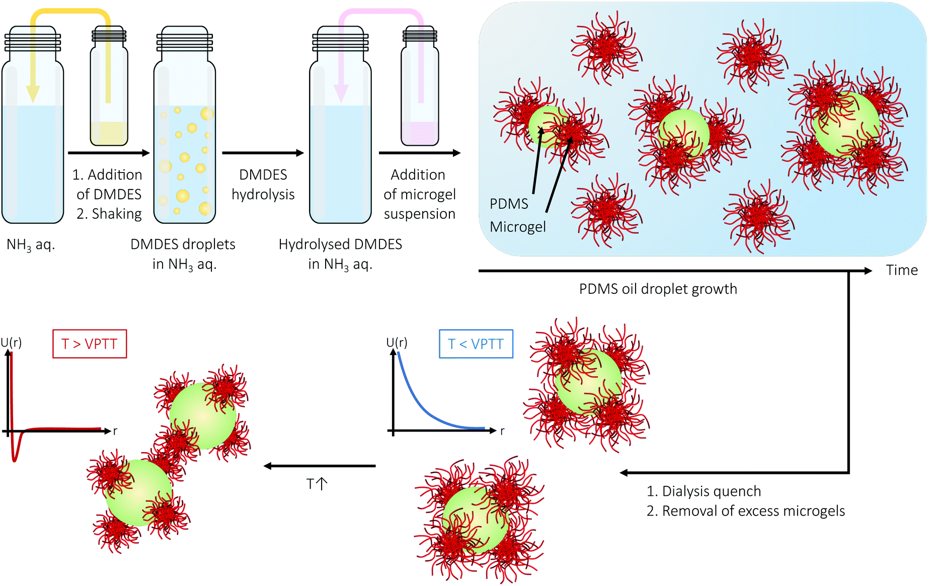 | ||
| Fig. 1 Synthesis of PDMS oil droplets in the presence of PNIPAM microgels yields colloidal molecules with a small number of discrete interaction sites following dialysis that quenches further oil droplet growth. The use of PNIPAM microgel as interaction sites will allow for convenient tuning of the interactions between the colloidal molecules, from soft repulsive (T < VPTT) to attractive (T > VPTT) through an increase of temperature across the microgels' VPTT. | ||
2 Materials and methods
2.1 Chemicals
N-Isopropylacrylamide (NIPAM, 97%, Aldrich), N,N′-methylenebis(acrylamide) (BIS, 99%, Sigma-Aldrich), acrylic acid (AAc, 99.5%, Acros Organics), methacryloxyethyl thiocarbamoyl rhodamine B (MRB, Polysciences Inc.), sodium dodecyl sulphate (SDS, >99%, Duchefa Biochemie), potassium persulphate (KPS, >99%, Sigma-Aldrich), pyrromethene 546 (PM546, Exciton Inc.), dimethyldiethoxysilane (DMDES, 97%, Acros Organics) and ammonia (ammonium hydroxide solution, 28.0–30.0% NH3 basis, Sigma-Aldrich) were all used as received. Water was purified using a Milli-Q water purification system (resistivity 18.2 MΩ cm, Millipore).2.2 Microgel synthesis
Microgels were prepared by free radical precipitation polymerisation.75 In a three-necked flask, 2.87 g (25.4 mmol) NIPAM, 0.22 g (1.43 mmol, 5.0 mol%) BIS, 0.16 g (2.22 mmol, 7.5 mol%) AAc, 4.0 mg MRB and 6.5 mg SDS were dissolved by stirring in 190.0 g of water. Upon complete dissolution of the reactants, the necks of the flask were fitted with a septum, a nitrogen inlet and a condenser, after which the flask was immersed into an oil bath at 70 °C. During warm-up, the solution was purged with nitrogen under stirring. After 30 min, when the temperature was equilibrated and the solution was well purged, polymerisation was initiated through addition of 77.8 mg KPS in 5.0 g of water. A gradual increase in turbidity was observed over the 10 min following KPS addition. The reaction was allowed to proceed for 4 hours under a nitrogen mantle, after which the suspension was allowed to cool down to room temperature. The suspension was then filtered through glass wool to remove any traces of coagulum, and was thereafter purified by repeated cycles of centrifugation, decantation and redispersion.2.3 PDMS oil droplet synthesis
PDMS oil droplet syntheses were (typically) performed in 20 ml glass vials with screw-cap, cleaned by soaking in 4% NaOH over night, in 14% HNO3 for 10 min, and then thoroughly washed with water. 100 μl (0.01 v/v) of DMDES (either unstained or stained with 1.0 mg PM546 per 10 ml of DMDES) was added to 9900 μl of 0.1 v/v aqueous ammonia solution (corresponding to a pH of 12.3; the pH was never measured after addition of DMDES as we suspect that DMDES might react with the glass surface of the pH probe) followed by vigorous shaking by hand for 30 s. The solution was allowed to rest during oil droplet formation and growth. After two hours, a slight increase in turbidity was observed, which continued to increase during oil droplet growth. The resulting emulsions were (sometimes) dialysed (MWCO 12–14 kDa, Spectrum Labs) against water (100 times the sample volume) in order to suppress further oil droplet growth and to, as described elsewhere,72 increase emulsion stability.2.4 Preparation of microgel-decorated silicon oil droplets
The microgel-decorated silicon oil droplets presented in Fig. 10 were obtained by adding 50 μl of PM546-dyed low-viscosity (5 cSt) silicon oil (Aldrich) (1.0 mg PM546 per 10 ml) to 350 μl of 0.5 wt% microgel suspension and vortexing the mixture for 2 min. The ones presented in Fig. 13 were instead prepared from 100 μl of silicon oil and 400 μl of 0.2 wt% 1![[thin space (1/6-em)]](https://www.rsc.org/images/entities/char_2009.gif) :1 (number:number) PNIPAM:PNIPMAM microgel suspension.
:1 (number:number) PNIPAM:PNIPMAM microgel suspension.
2.5 Preparation of colloidal molecules
(Typically) 50 μl (0.01 v/v) of DMDES was added to 3700 μl of aqueous ammonia solution followed by vigorous shaking by hand for 30 s. As soon as the foam had set, 1250 μl of 2.0 wt% microgel suspension was added; the final concentrations of ammonia and microgels were 0.1 v/v and 0.5 wt%, respectively. After swirling to mix the two components, the mixture was allowed to rest during oil droplet formation and growth, during which colloidal molecule-like microgel-decorated oil droplets were formed. At a desired stage, further growth was suppressed by dialysis (MWCO 12–14 kDa, Spectrum Labs) against water, which also served to improve the stability of the system.The microgel-decorated oil droplets presented in Fig. 14 were prepared in the same way as just described, but with the amounts specified in Table 1.
2.6 Removal of excess microgels
Isolation of colloidal molecules through removal of excess microgels was achieved using a DLD device. A detailed description of the device can be found in the ESI.† A dilute suspension (≈0.25 wt%) of microgel-decorated oil droplets and excess microgels was introduced through the two sample inlets at the sides of the array, whereas water was introduced through the central inlet. The pressures applied to the inlets (≈100 mbar) were fine-tuned to ensure a balanced flow aligned along the direction of the channel. The device was run for 5 hours, which generated ≈50 μl of suspension in the cluster outlet.2.7 Characterisation techniques
3 Results and discussion
Not only are PNIPAM microgels easy to prepare, as highly monodisperse systems, from cheap starting materials via standard precipitation polymerisation methods,75 but due to their response (size, volume fraction, softness, interactions) to external stimuli – temperature in particular – they have received extreme attention in both fundamental and application-oriented science.44–50 Their temperature-response is exploited also in the present study, where microgels are used as building-blocks for colloidal molecules, playing the roles of interaction sites with repulsive or attractive interactions depending on the temperature. In contrast to the two other methods for preparing microgel-based colloidal molecules that were only very recently reported by our group – which involve evaporation-induced clustering of microgels confined in water droplets80 and microgel clustering induced by electrostatic interactions,81 respectively – the colloidal molecules introduced in the present paper consist of a central PDMS oil emulsion droplet serving as an anchor for a limited number of microgels that adsorb to the oil–water interface.3.1 The microgel building blocks
With these considerations in mind, the microgels used in the present study were designed to have a large magnitude of charge. Besides charges originating from the free radical initiator KPS, AAc was co-polymerised in order to incorporate additional negative charges (carboxylic acid groups). NIPAM was chosen as main monomer due to the low, easily accessible VPTT of the corresponding polymer, PNIPAM. BIS was used as cross-linker and the polymerisable rhodamine derivative MRB was incorporated to enable fluorescence CLSM studies. The polymerisation followed standard one-batch, free radical precipitation polymerisation.75 Following purification, the microgels were imaged by CLSM. Whereas a 0.1 wt% suspension (Fig. 2A) exhibited fluid behaviour, a crystalline particle arrangement was observed at 3.7 wt% (Fig. 2B). Crystallisation, which reflects a high degree of particle size monodispersity, was also evident from the suspension's ‘structural color’ caused by Bragg diffraction.
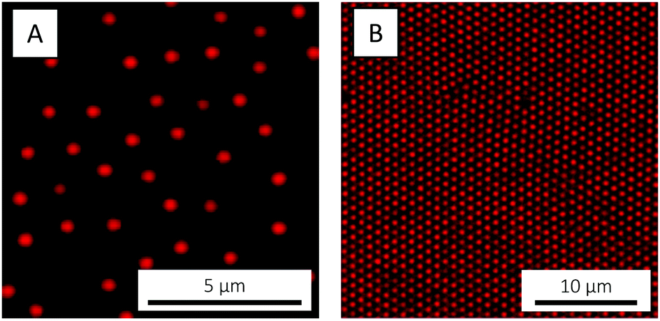 | ||
| Fig. 2 CLSM micrographs of the PNIPAM-co-AAc microgels at (A) 0.1 and (B) 3.7 wt%, respectively, recorded at 20 °C. In (A), the microgels are electrostatically adsorbed to an amine-functionalised cover slip. | ||
 | ||
| Fig. 3 Evolution of RH with T for the PNIPAM-co-AAc microgels, measured by DLS in water (filled gray squares) and in 1 mM HCl (pH 3.0) (filled red circles), respectively. The error bars are typically smaller than the symbol size. | ||
The observed decrease in particle size occurring on the single-particle level on crossing the VPTT is naturally reflected in a reduction of the total particle volume fraction ϕ. For the microgels used in the present study, this could be directly visualised by CLSM: here, a crystal was melted into a fluid state as the temperature was raised from 20 to 40 °C (Fig. 4). The crystal state was recovered on return to 20 °C (not shown). Such temperature cycling – known as annealing – has been used elsewhere to effectively remove defects in microgel crystals.84 The fact that the phase behaviour55 can be controlled and the phase diagram explored so easily in situ with temperature is a clear advantage of microgels as compared to hard sphere building blocks.
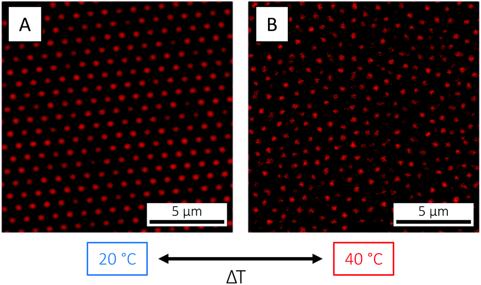 | ||
| Fig. 4 CLSM micrographs of the PNIPAM-co-AAc microgels at 3.7 wt%, at (A) 20 (T < VPTT) and (B) 40 °C (T > VPTT), respectively, showing the reversible transition from an arrested, crystalline state below the VPTT to a fluid state above as the particle size and volume fraction decreases. | ||
With the reduction in particle size observed by DLS, an increase in the magnitude of the electrophoretic mobility μ naturally follows as the charges originating from initiator residuals and carboxylic acid groups become condensed and effectively contribute to an increase in the apparent surface charge. With the microgels suspended in water, μ increased from −1.90 ± 0.03 × 10⁻⁸ m2 V−1 s−1 at 20 °C to −3.39 ± 0.06 × 10⁻⁸ m2 V−1 s−1 at 50 °C. We acknowledge the fact that μ also varies with pH through the degree of deprotonation of the carboxylic acid groups, but this was not further investigated in the present study.
In addition to size and magnitude of charge, also the inter-particle interactions of PNIPAM microgels are affected by changes in temperature: as previously described, under conditions where the electrostatic interactions are screened, an increase in temperature across the VPTT induces a transition from a soft repulsive state to a hard sphere-like one with an added short-range attraction. For the microgels used in the present study, this behaviour was visualised by CLSM. Here, an increase in temperature from 20 to 40 °C, in 5 mM HCl in order to suppress and screen the microgel charges, resulted in the formation of a volume-spanning gel network due the aforementioned repulsive-to-attractive transition (Fig. 5). The transition was completely reversible, and the fluid state was restored on cooling down to below the VPTT. It is worth noticing that in pure water (Fig. 4) or in 1 mM HCl (Fig. 3) the electrostatic repulsion was strong enough to prevent the particles from flocculating above the VPTT.
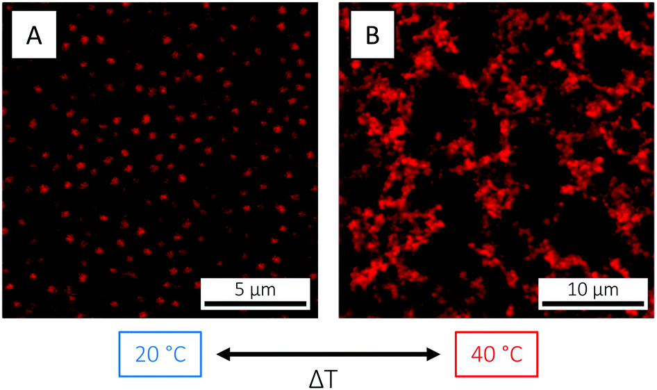 | ||
| Fig. 5 CLSM micrographs of the PNIPAM-co-AAc microgels at 2.5 wt% and in 5 mM HCl (pH 2.3), at (A) 20 (T < VPTT) and (B) 40 °C (T > VPTT), respectively, illustrating the reversible transition from a repulsive (fluid) state below the VPTT to an attractive (gel) state above the VPTT. (A) is a xy snapshot from a video recorded in bulk solution, whereas (B) is a maximum intensity projection constructed from 22 xy frames collected over a z-distance of 5.29 μm. | ||
3.2 PDMS oil droplets
In addition to high droplet monodispersity and excellent emulsion stability, the use of PDMS as the oil phase offers two important advantages. First, the refractive index of PDMS (1.40) is only slightly higher than that of water (1.33). This has, in turn, two important implications: that the corresponding emulsions scatter light only very weakly and that the attractive droplet–droplet van der Waals attractions are weak. Whereas weak scattering is beneficial for microscopy studies, weak van der Waals forces means that the interactions of microgel-decorated oil droplets is (mainly) governed by microgel–microgel interactions. Second, the fact that PDMS is slightly less dense than water (0.91 g ml−1) compensates for the microgels being slightly more dense, and it can be assumed that the resulting microgel-decorated oil droplets are (more or less) density-matched with water. This allows for microscopy studies in bulk solution without significant sedimentation or creaming during the time frame of the experiment.
Guided by previous studies on organosilane polymerisation,72,87 in the present study PDMS oil droplets were prepared from 0.01 v/v DMDES in 0.1 v/v ammonia solution, corresponding to a pH of 12.3. As anticipated, the resulting oil droplets showed, by emulsion standards, a remarkably high degree of monodispersity, as revealed when a 48 hour-old emulsion was studied by CLSM (Fig. 6 and Video S1, ESI†). Based on the micrographs, the oil droplet diameter was estimated to about 1.5 μm. The zeta potential ζ of the droplets was measured to −110.6 ± 2.4 mV, signifying them being highly colloidally stable.
 | ||
| Fig. 6 (A) Bright-field and (B) fluorescence CLSM micrographs of monodisperse PDMS oil droplets prepared from 0.01 v/v PM546-dyed DMDES in 0.1 v/v ammonia and grown for 48 hours. The emulsion was not dialysed. The micrographs are xy snapshots from Video S1, ESI.† | ||
Prior to any attempts at dialysis quenching, the evolution of the oil droplet size with time during the first 24 hours was studied by DLS. Here, the 3D cross-correlation technique76,77 was employed to allow for the measurements to be performed in situ while effects of multiple scattering were being suppressed. The measurements were performed at four different scattering angles and any measurement coinciding with the minima of the form factor (characterised by a low intercept in the correlation function) was excluded from the data set. As seen in Fig. 7, the oil droplet radius initially increases steeply and thereafter the growth begins to slowly level off. After 24 hours of growth, the radius approaches 500 nm. As it took a finite time to prepare the sample for measurements, the first 10 minutes were not monitored and the curve is therefore missing a lag phase corresponding to the nucleation period as well as the 0–100 nm growth period. As the full growth curve was not captured, no model has been fitted to the data to describe the growth process in more detail.
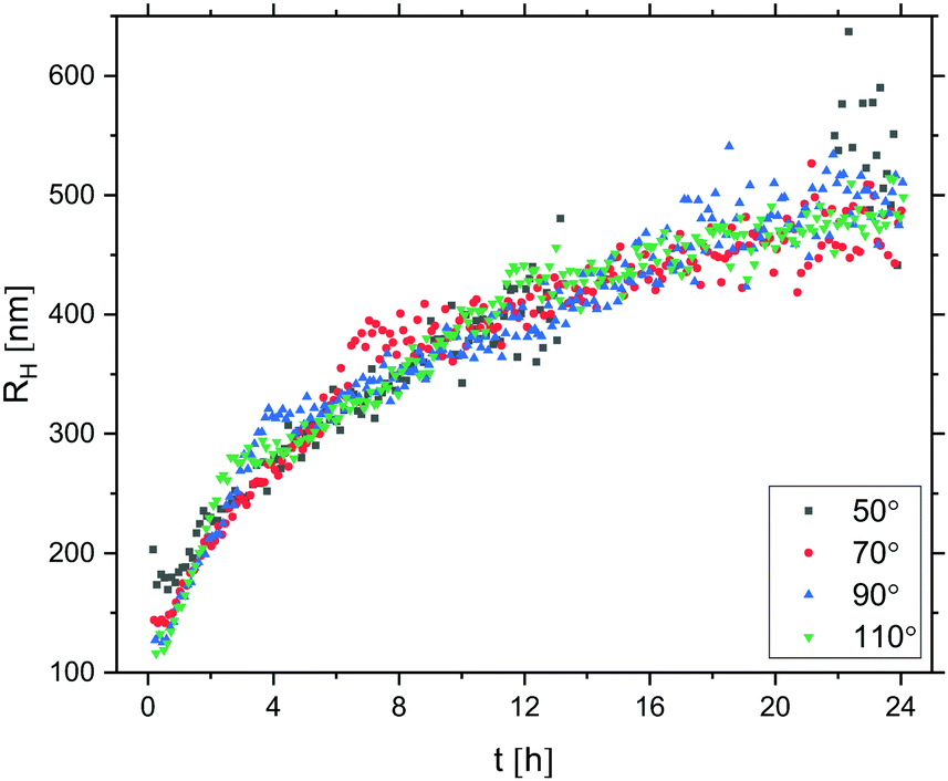 | ||
| Fig. 7 PDMS oil droplet growth probed via the evolution of RH with time t up to 24 h, measured by 3D DLS at four different scattering angles. t = 0 corresponds to the time of addition of DMDES to the ammonia solution; t = 10 min corresponds to the start of the measurements. Correlation functions with an intercept lower than 0.2 (due to coincidence with P(q) minima) have been excluded from the data sets. The oil droplets were prepared from 0.01 v/v DMDES in 0.1 v/v ammonia solution. | ||
After 24 hours of oil droplet growth, the turbidity of the emulsion prevented further in situ light scattering measurements. At this point the emulsion was instead diluted ten times in order to effectively reduce the oil droplet concentration and growth rate before subjecting it to SLS measurements. The presence of well-defined minima in the resulting I(q) trace (Fig. 8) points to a high degree of oil droplet size monodispersity, which was quantified by fitting the form factor P(q) with a Mie scattering profile of homogeneous solid spheres; considering that the sample was very dilute, we assumed inter-particle interactions to be negligible and consequently I(q) ∝ P(q). The fit, which included a Gaussian smoothing to mimic polydispersity, yielded an oil droplet radius RSLS of 473 nm – in good agreement with RH obtained from DLS measurements – and a polydispersity of 5.0%.
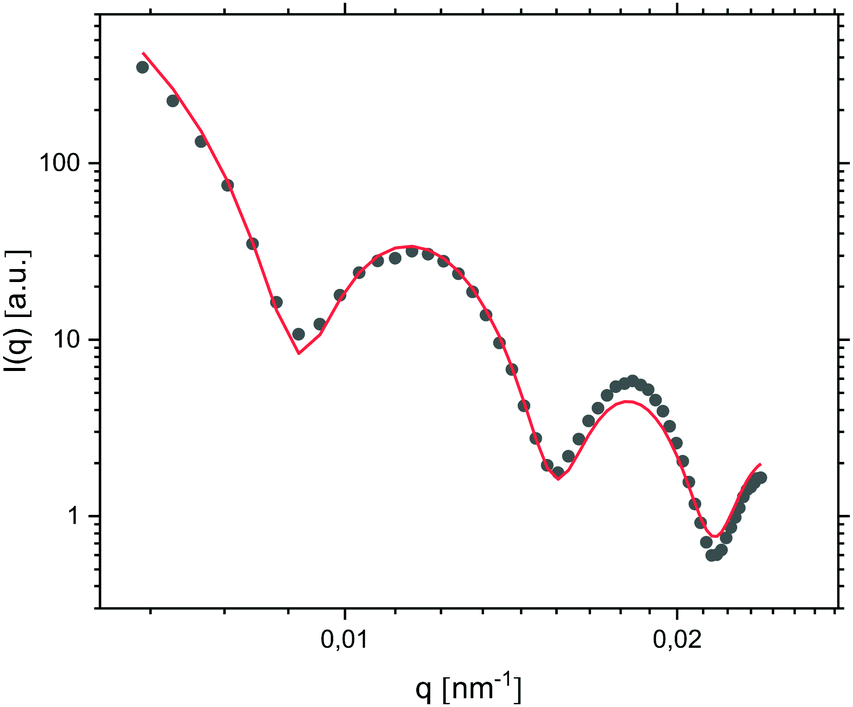 | ||
| Fig. 8 I(q) trace measured by SLS (symbols) together with a Mie fit of the form factor (line; radius 473 nm and polydispersity 5.0%), for oil droplets prepared from 0.01 v/v DMDES in 0.1 v/v ammonia solution and grown for 24 hours. The emulsion was diluted ten-fold prior to measurements. | ||
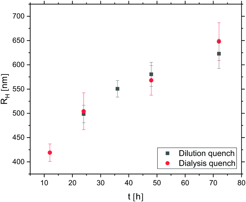 | ||
| Fig. 9 Evolution of RH of oil droplets – prepared from 0.01 v/v DMDES in 0.1 v/v ammonia solution – with growth time t. Data represented by filled grey squares were obtained following a ten-fold dilution of (an aliquot of) the emulsion whereas data represented by red circles were obtained following a 72 hours dialysis quench. | ||
3.3 Colloidal molecules
The interfacial activity of the microgels used in the present paper was assessed using large, low-viscosity silicon oil droplets to provide an oil–water interface. The oil droplets were prepared by simply dispersing silicon oil in a microgel suspension. The resulting (polydisperse) emulsion was studied by CLSM, where the affinity of the microgels for the oil–water interface was confirmed by the presence of microgel-decorated oil droplets (Fig. 10). The oil droplets host and mediate long-range ordering of the microgels into 2D hexagonal crystals (Fig. 10A and B), enabled by the liquid nature of the oil that allows for lateral rearrangements in the interface. 2D microgel crystals have also been observed at the phospholipid bilayer membrane of giant unilamellar vesicles (GUVs) in the case of fluid lipid chains.96,97 The microgel centre-to-centre distance in the 2D crystal, about 700 nm, is significantly smaller than expected from the microgels’ hydrodynamic diameter DH (956 nm), which is a reflection of their soft repulsive potential and the ability of their loosely cross-linked shells to interpenetrate, deform and compress.98–100
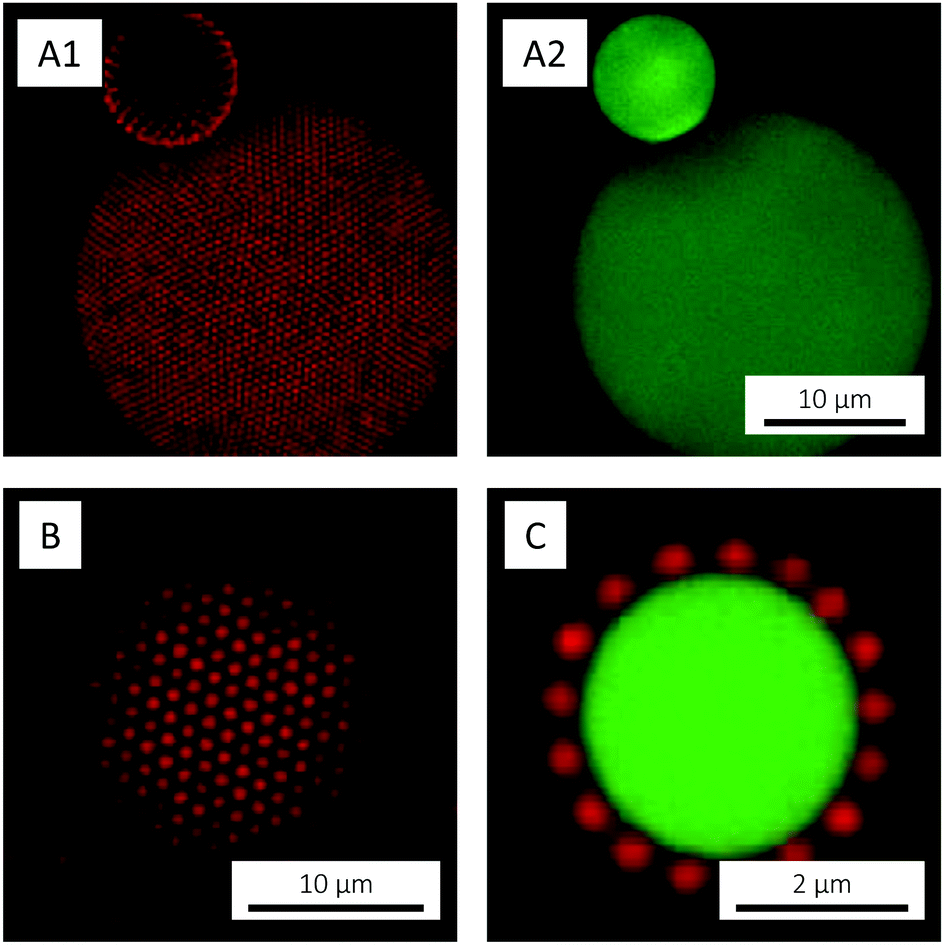 | ||
| Fig. 10 CLSM micrographs of PM546-dyed silicon oil emulsion droplets decorated with PNIPAM-co-AAc microgels, recorded at 20 °C. (A1) and (A2) are maximum intensity projections constructed from 15 xy frames collected over a z-distance of 5.29 μm and show the red and green channel, respectively; (B) and (C) are simple xy images. In (B) only the red channel is shown, whereas the two channels have been merged in (C) to visualise the position of the microgels with respect to the interface. | ||
Due to their hydrophilic nature, the adsorbed microgels were observed to mainly reside on the water-side of the interface where their spherical shape was retained (Fig. 10C). Similar observations have been made for closely related PNIPAM-co-methacrylic acid microgels at the water/n-heptane interface, using freeze-fracture shadow casting (FreSCa) cryo-SEM.70 These microgels showed only a small protrusion – corresponding to about 20% of the bulk diameter – into the oil and were reported to retain their bulk shape on the water-side. In the oil, however, substantial flattening was reported. This ‘fried-egg’-like conformation, with the loosely crosslinked particle periphery spreading in the interface, is well known to be adopted by microgels at interfaces,67–70 but was not observed in the present paper, however. We believe that such observations were prohibited due to the low polymer density and the consequently low fluorophore abundance in the ‘egg white region’, in the loosely crosslinked particle periphery capable of deforming and spreading in the interface. The use of cryo-SEM would allow for any such deformations to be studied with better resolution, but this was not pursued in the present study.
Considering the relatively large size and high electrophoretic mobility (478 ± 35 nm and −1.90 ± 0.03 × 10⁻⁸ m2 V−1 s−1 at 20 °C, respectively) of the microgels, and comparing to a study involving smaller, less charged, pure PNIPAM microgels (Fig. S2, ESI†), we hypothesised that the target colloidal molecules, with (around) four microgel interaction sites per droplet, would not form until after the initially steep oil droplet growth period (Fig. 7). This is beneficial as it means that less demands are put on the efficiency of the dialysis quench that serves to limit further oil droplet growth. In order to localise the position in time at which the target colloidal molecules have formed, the evolution of the number of microgels per oil droplet was studied by imaging the sample by CLSM after 12, 18, 24, 36, 48 and 72 hours of oil droplet growth (Fig. 11). As in the emulsion experiments, the DMDES and ammonia amounts were 0.01 v/v and 0.1 v/v (pH 12.3), respectively. In order to suppress the formation of bridging aggregates of alternating oil droplets and microgels, a large excess of microgels was used (0.5 wt%); Fig. S3 (ESI†) shows the detrimental effect of not using an excess of microgels.
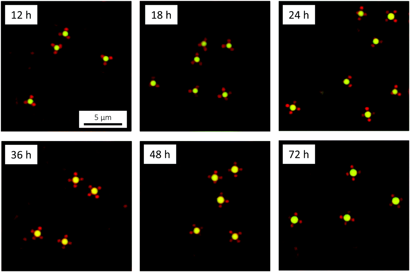 | ||
| Fig. 11 xy CLSM micrographs recorded at 20 °C, showing the evolution of the size of the microgel-decorated oil droplets with time. The assemblies are adsorbed to the glass cover slip. The oil droplets were prepared from 0.01 v/v DMDES in 0.1 v/v ammonia solution and grown in the presence of 0.5 wt% microgels. | ||
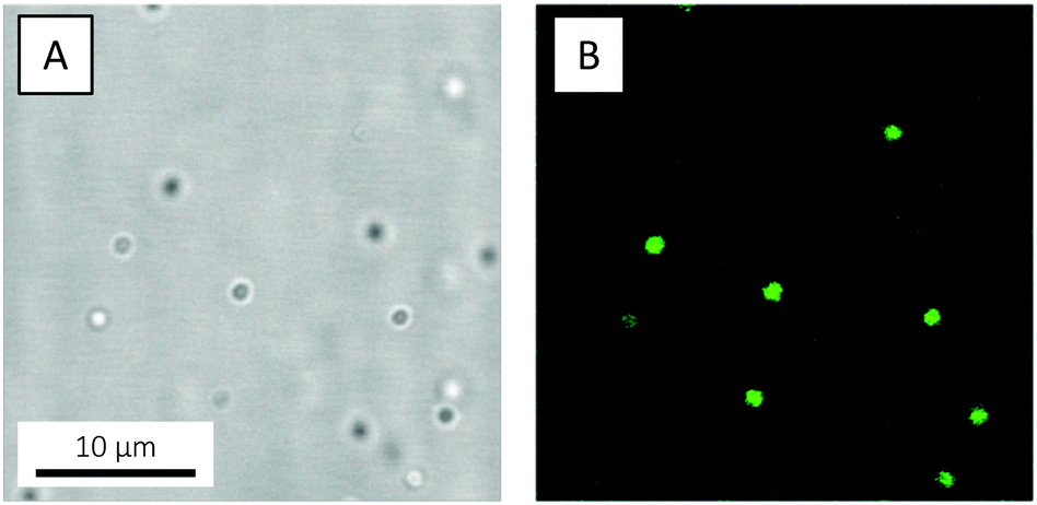
Already at the first time point investigated, at 12 hours of oil droplet growth, small, colloidal molecule-like microgel-decorated oil droplets were observed. Due to the high monodispersity of the oil droplets, the assemblies display a remarkably narrow size distribution: a single type of assembly was observed together with a very small number of ‘dimer aggregates’ formed by the bridging of two oil droplets by one microgel particle. Judging from the xy micrograph in Fig. 11 (Fig. S4, ESI,† shows additional micrographs), the oil droplets each carry three microgels at this point. However, studies of the assemblies in bulk solution, where they tumble around and their geometry can be more clearly visualised, reveal that each oil droplet in fact carries four microgels, well separated on the surface of the droplet, in a tetrahedral-like arrangement (Video S2, ESI†). As seen in Fig. 11, the number of microgels in the cross-section increases with time to four (sometimes five) at 72 hours, the last time point investigated. At 72 hours, the oil droplets carry about six to seven microgels in total, as deduced from studies in bulk solution.
The (nominal) Dc of the DLD device used in the present paper was Dc = 1.18 μm (ESI†), as estimated by the empirical expression in ref. 107. This Dc was large enough to suppress lateral displacement of the excess microgels while still allowing for displacement of the colloidal molecules. Unfortunately, however, despite extensive surface treatment, the microgels were observed to stick to the walls and posts of the device – a problem that grew more and more severe with increasing run time. This sticking affects, first of all, the effective post size and post spacing, which in turn influence Dc. Second, sticking eventually results in the formation of clogs that disrupt the fluid flow through the device. Both of these factors serve to decrease the resolution of the sorting, and are the reasons why a small number of free microgels ended up as contaminants in the colloidal molecule reservoir. Whereas alternative surface treatments need to be investigated in order to relieve the sticking problem, the fact that we already obtain an almost pure colloidal molecule sample (Video S4, ESI†) points to the usefulness of this sorting approach for the separation of excess microgels from the target colloidal molecules. CLSM micrographs of colloidal molecules harvested following DLD sorting are shown in Fig. 12.
 | ||
| Fig. 12 xyz maximum intensity projections, constructed from 15 xy frames collected over a z-distance of 2.94 μm and recorded at 20 °C, showing isolated colloidal molecules of tetrahedral geometry adsorbed to the glass cover slip. | ||
In this part of the study, we used two different microgels, one rhodamine-labelled, 401 nm (RH at 20 °C) PNIPAM-co-AAc microgel and one unlabelled, 355 nm PNIPMAM-co-AAc one. Both were moderately crosslinked (4.8 and 4.9 mol% BIS, respectively) and had an AAc content of 4.8 mol%. Detailed descriptions of the synthesis procedures and basic characterisation by DLS and zetametry are provided in the ESI.† Video S5 (ESI†) demonstrates that temperature can indeed be used to selectively render the PNIPAM particles attractive, while the PNIPMAM particles remain repulsive. It shows a 1:1 mixture of the two microgels at 35 °C, in between the two VPPTs. Here, the PNIPAM microgels are attractive and have formed a volume-spanning network, whereas the PNIPMAM ones are still repulsive, remain fully dispersed and exhibit Brownian motion in the liquid parts that are not occupied by the solid PNIPAM particle network.
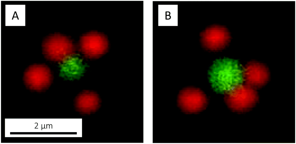
Before attempting to prepare colloidal molecules, we studied the simultaneous adsorption of the two types of microgels – in a 1:1 number ratio – to the interface of an emulsion comprising large silicon oil droplets. Both microgels were observed to adsorb to the interface, arranging in a (distorted) hexagonal pattern (Fig. 13). Here, a quite strong preference for adsorption of PNIPAM over PNIPMAM was recognised. This preferred adsorption of PNIPAM over PNIPMAM obviously has important consequences when trying to prepare colloidal molecules or patchy particles with a defined number of PNIPAM particles well separated by PNIPMAM particles at the oil droplet interface. A simple extension of the in situ microgel-Pickering emulsion method to a binary mixture of PNIPAM and PNIPMAM would always lead to a large excess of PNIPAM particles at the oil droplet surface, whereas we require the opposite arrangement for our application. We thus resort to a two-step procedure as described in the following paragraph. We did not investigate the origin of this preferential adsorption in more detail, as this would require a systematic study varying a number of parameters such as polymer identity and particle size, softness and charge. Instead, we now turned to smaller oil droplets and the preparation of colloidal molecules.
 | ||
| Fig. 13 CLSM micrographs of a PM546-dyed silicon oil emulsion droplet simultaneously decorated with PNIPAM-co-AAc and PNIPMAM-co-AAc microgels, recorded at 20 °C, in (A) fluorescence and (B) bright-field mode. | ||
A small series of consecutive experiments, outlined in Table 1, was now performed in order to reach the target patchy colloidal molecules. First, microgel-decorated oil droplets were prepared with the two microgels individually. After 24 hours of oil droplet growth, the resulting assemblies were studied by CLSM (Fig. 14A and B), revealing, for both microgels, similar monodisperse structures as those shown in Fig. 11. Deduced from studies in bulk solution, the oil droplets carried about six microgels at this point. Next, the in situ reaction was performed with a 1:1 mixture of the two microgels (Fig. 14C). Here, the strong preferential adsorption of the PNIPAM microgels became clear: the oil droplets were exclusively decorated by the PNIPAM microgels and the same structures as in Fig. 14A were obtained. In order to boost adsorption of the PNIPMAM microgels, in the next step a 1:5 PNIPAM:PNIPMAM mixture was used (Fig. 14D). However, this merely resulted in aggregation by a bridging mechanism as the PNIPAM microgels are still preferentially adsorbed but no longer present in large excess. In order to work around the problem, still using a 1:5 ratio of the two microgels, we delayed the addition of the PNIPAM microgels to 6 hours following the start of the oil droplet synthesis (Fig. 14E). At this stage, the oil droplets were already decorated with PNIPMAM microgels, and further growth beyond this point would then allow for PNIPAM microgels to preferentially adsorb. With this approach, we could successfully obtain patchy colloidal molecules carrying, typically, one or two well-separated PNIPAM interaction sites. Extending the second growth step to longer times would then increase the number of PNIPAM particles and thus the number of patches or interaction sites. Whereas the current paper only summarises the results of our initial experiments, this constitute a first proof-of-concept for this approach for patchy colloidal molecule preparation.
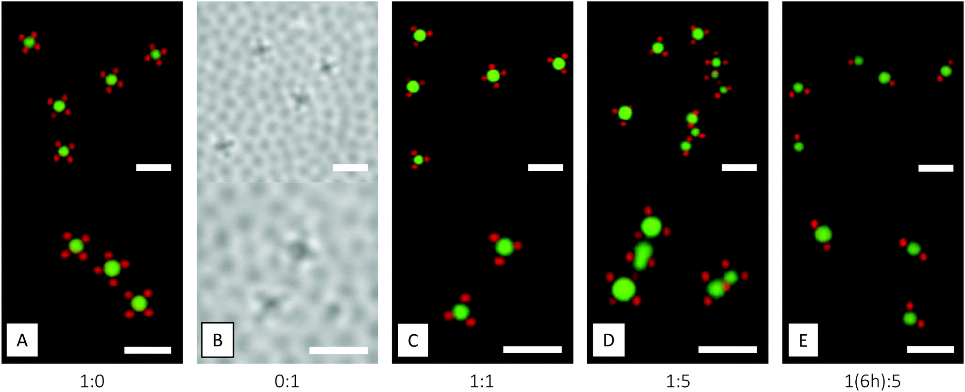 | ||
| Fig. 14 CLSM micrographs, recorded at 20 °C, showing 24 hour-old microgel-decorated oil droplets prepared with different PNIPAM-co-AAc:PNIPMAM-co-AAc number ratios. The assemblies are adsorbed to the glass cover slip. Scale bars are 2 μm. | ||
4 Conclusions
Control of the positions and number of neighbours in a self-assembling structure has been a long-sought goal in material science, motivated by the strive to prepare new ordered structures and materials with novel properties. Such control can be realised using building blocks possessing a limited number of well-defined interaction sites, capable of mediating a limited number of highly directional interactions.In this paper, the development and use of an in situ microgel-Pickering emulsion route for the preparation of colloidal molecules with a small number of well-defined interaction sites was reported. The use of temperature-responsive microgels as building blocks – which are cheap and easy to synthesise – together with easy up-scaling, makes the herein reported method a cutting edge strategy for obtaining large quantities of colloidal molecules where the interactions can be easily tuned for a more controlled assembly. Compared to the more complicated routes to microgel-based colloidal molecules previously reported, which involves the formation of binary crystals,36,37 our method is highly attractive because of its simplicity, and in addition offers superior flexibility as the valency can be easily controlled through the oil droplet size. Whereas the present paper demonstrates the feasibility and flexibility of the microgel-Pickering emulsion route, future studies will have to quantitatively address the directional interactions, as well as the colloidal molecule phase behaviour and self-assembly as a function of concentration and temperature.
As demonstrated in Fig. 14E, the extension of the microgel-Pickering emulsion method to binary PNIPAM–PNIPMAM mixtures allows us to prepare colloidal molecules with well-separated interaction sites that are ideal to study the influence of attractive patches on self-assembly or diffusion. These colloidal molecules are no longer restricted to a distribution of interaction sites given by the typical compact and highly symmetrical cluster structures that are formed with a single class of particles. Instead, the active interaction sites formed by the PNIPAM microgels can take up different structures and symmetries that for example mimic the structure of a H2O molecule, thus offering new possibilities for the use of colloidal model systems in condensed matter physics. Finally, patchy colloid models have been increasingly used to theoretically model the phase behaviour and the dynamics of proteins in crowded solutions as for example present in the living cell. Here, our method offers an interesting route for the creation of protein-mimicking colloidal complexes with corrugated, patchy surfaces that resemble the hydrophilic/hydrophobic and charged patches present on globular proteins. This will allow for detailed model studies under highly controlled conditions, where CLSM-based multiple particle tracking can for example provide unique information on the effects of patchiness on short and long time diffusion in crowded systems.116,117
Conflicts of interest
There are no conflicts to declare.Acknowledgements
This work was financially supported by the European Research Council (ERC-339678-COMPASS) and the Knut and Alice Wallenberg Foundation (KAW 2014.0052). The authors thank Niels Boon for fitting of SLS data, Robin Kämpe for writing the MATLAB scripts for 3D DLS data processing, and Stefan H. Holm and Jonas O. Tegenfeldt for designing the DLD device. DLD device fabrication was carried out in Lund Nano Lab.References
- C. De Kruif, P. Rouw, J. Jansen and A. Vrij, J. Phys., Colloq., 1985, 46, 295–308 Search PubMed.
- P. Pusey and W. Van Megen, Nature, 1986, 320, 340–342 CrossRef CAS.
- P. Pusey, W. C. Poon, S. Ilett and P. Bartlett, J. Phys.: Condens. Matter, 1994, 6, A29–A36 CrossRef CAS.
- U. Gasser, E. R. Weeks, A. Schofield, P. Pusey and D. Weitz, Science, 2001, 292, 258–262 CrossRef CAS PubMed.
- V. J. Anderson and H. N. Lekkerkerker, Nature, 2002, 416, 811–815 CrossRef CAS PubMed.
- K. N. Pham, A. M. Puertas, J. Bergenholtz, S. U. Egelhaaf, A. Moussad, P. N. Pusey, A. B. Schofield, M. E. Cates, M. Fuchs and W. C. Poon, Science, 2002, 296, 104–106 CrossRef CAS PubMed.
- A. Yethiraj and A. van Blaaderen, Nature, 2003, 421, 513–517 CrossRef CAS PubMed.
- W. Poon, Science, 2004, 304, 830–831 CrossRef CAS.
- V. W. de Villeneuve, R. P. Dullens, D. G. Aarts, E. Groeneveld, J. H. Scherff, W. K. Kegel and H. N. Lekkerkerker, Science, 2005, 309, 1231–1233 CrossRef CAS PubMed.
- P. Schall, I. Cohen, D. A. Weitz and F. Spaepen, Nature, 2006, 440, 319–323 CrossRef CAS PubMed.
- P. J. Lu and D. A. Weitz, Annu. Rev. Condens. Matter Phys., 2013, 4, 217–233 CrossRef CAS.
- B. Li, D. Zhou and Y. Han, Nat. Rev. Mater., 2016, 1, 15011 CrossRef CAS.
- A. van Blaaderen, Science, 2003, 301, 470–471 CrossRef CAS.
- E. Duguet, A. Désert, A. Perro and S. Ravaine, Chem. Soc. Rev., 2011, 40, 941–960 RSC.
- K. Ho, C. T. Chan and C. M. Soukoulis, Phys. Rev. Lett., 1990, 65, 3152–3155 CrossRef CAS.
- Z. Zhang, A. S. Keys, T. Chen and S. C. Glotzer, Langmuir, 2005, 21, 11547–11551 CrossRef CAS.
- E. G. Noya, C. Vega, J. P. Doye and A. A. Louis, J. Chem. Phys., 2010, 132, 234511 CrossRef.
- F. Romano, E. Sanz and F. Sciortino, J. Chem. Phys., 2011, 134, 174502 CrossRef.
- D. Morphew, J. Shaw, C. Avins and D. Chakrabarti, ACS Nano, 2018, 12, 2355–2364 CrossRef CAS PubMed.
- Y. Yin and Y. Xia, Adv. Mater., 2001, 13, 267–271 CrossRef CAS.
- V. N. Manoharan, M. T. Elsesser and D. J. Pine, Science, 2003, 301, 483–487 CrossRef CAS PubMed.
- W. K. Kegel, D. Breed, M. Elsesser and D. J. Pine, Langmuir, 2006, 22, 7135–7136 CrossRef CAS PubMed.
- L. Hong, A. Cacciuto, E. Luijten and S. Granick, Nano Lett., 2006, 6, 2510–2514 CrossRef CAS.
- J.-W. Kim, R. J. Larsen and D. A. Weitz, Adv. Mater., 2007, 19, 2005–2009 CrossRef CAS.
- L. Hong, A. Cacciuto, E. Luijten and S. Granick, Langmuir, 2008, 24, 621–625 CrossRef CAS PubMed.
- D. J. Kraft, W. S. Vlug, C. M. van Kats, A. van Blaaderen, A. Imhof and W. K. Kegel, J. Am. Chem. Soc., 2008, 131, 1182–1186 CrossRef.
- D. J. Kraft, J. Groenewold and W. K. Kegel, Soft Matter, 2009, 5, 3823–3826 RSC.
- A. Perro, E. Duguet, O. Lambert, J.-C. Taveau, E. Bourgeat-Lami and S. Ravaine, Angew. Chem., Int. Ed., 2009, 121, 367–371 CrossRef.
- J.-G. Park, J. D. Forster and E. R. Dufresne, Langmuir, 2009, 25, 8903–8906 CrossRef CAS.
- S. Sacanna, W. Irvine, P. M. Chaikin and D. J. Pine, Nature, 2010, 464, 575 CrossRef CAS.
- Y. Wang, Y. Wang, D. R. Breed, V. N. Manoharan, L. Feng, A. D. Hollingsworth, M. Weck and D. J. Pine, Nature, 2012, 491, 51–55 CrossRef CAS.
- S. Sacanna, L. Rossi and D. J. Pine, J. Am. Chem. Soc., 2012, 134, 6112–6115 CrossRef CAS PubMed.
- D. J. Kraft, R. Ni, F. Smallenburg, M. Hermes, K. Yoon, D. A. Weitz, A. van Blaaderen, J. Groenewold, M. Dijkstra and W. K. Kegel, Proc. Natl. Acad. Sci. U. S. A., 2012, 109, 10787–10792 CrossRef CAS PubMed.
- N. B. Schade, M. C. Holmes-Cerfon, E. R. Chen, D. Aronzon, J. W. Collins, J. A. Fan, F. Capasso and V. N. Manoharan, Phys. Rev. Lett., 2013, 110, 148303 CrossRef PubMed.
- Y. Wang, Y. Wang, X. Zheng, G.-R. Yi, S. Sacanna, D. J. Pine and M. Weck, J. Am. Chem. Soc., 2014, 136, 6866–6869 CrossRef CAS.
- Q. Yuan, J. Gu, Y.-N. Zhao, L. Yao, Y. Guan and Y. Zhang, ACS Macro Lett., 2016, 5, 565–568 CrossRef CAS.
- L. Yao, Q. Li, Y. Guan, X. Zhu and Y. Zhang, ACS Macro Lett., 2018, 7, 80–84 CrossRef CAS.
- P.-E. Rouet, C. Chomette, E. Duguet and S. Ravaine, Angew. Chem., 2018, 130, 15980–15983 CrossRef.
- É. Ducrot, M. He, G.-R. Yi and D. J. Pine, Nat. Mater., 2017, 16, 652–658 CrossRef PubMed.
- M.-P. Valignat, O. Theodoly, J. C. Crocker, W. B. Russel and P. M. Chaikin, Proc. Natl. Acad. Sci. U. S. A., 2005, 102, 4225–4229 CrossRef CAS PubMed.
- D. Nykypanchuk, M. M. Maye, D. Van Der Lelie and O. Gang, Nature, 2008, 451, 549–552 CrossRef CAS PubMed.
- Y. Wang, Y. Wang, X. Zheng, É. Ducrot, J. S. Yodh, M. Weck and D. J. Pine, Nat. Commun., 2015, 6, 7253 CrossRef CAS PubMed.
- Y. Wang, Y. Wang, X. Zheng, É. Ducrot, M.-G. Lee, G.-R. Yi, M. Weck and D. J. Pine, J. Am. Chem. Soc., 2015, 137, 10760–10766 CrossRef CAS.
- R. Pelton and P. Chibante, Colloids Surf., 1986, 20, 247–256 CrossRef CAS.
- B. R. Saunders and B. Vincent, Adv. Colloid Interface Sci., 1999, 80, 1–25 CrossRef CAS.
- R. Pelton, Adv. Colloid Interface Sci., 2000, 85, 1–33 CrossRef CAS.
- M. Das, H. Zhang and E. Kumacheva, Annu. Rev. Mater. Res., 2006, 36, 117–142 CrossRef CAS.
- L. A. Lyon and A. Fernandez-Nieves, Annu. Rev. Phys. Chem., 2012, 63, 25–43 CrossRef CAS PubMed.
- H. Kawaguchi, Polym. Int., 2014, 63, 925–932 CrossRef CAS.
- J. Brijitta and P. Schurtenberger, Curr. Opin. Colloid Interface Sci., 2019, 40, 87–103 CrossRef CAS.
- M. Karg, A. Pich, T. Hellweg, T. Hoare, L. A. Lyon, J. J. Crassous, D. Suzuki, R. A. Gumerov, S. Schneider and I. I. Potemkin, et al. , Langmuir, 2019, 35, 6231–6255 CrossRef CAS.
- M. Heskins and J. E. Guillet, J. Macromol. Sci., Chem., 1968, 2, 1441–1455 CrossRef CAS.
- H. G. Schild, Prog. Polym. Sci., 1992, 17, 163–249 CrossRef CAS.
- M. Shibayama and T. Tanaka, in Responsive Gels: Volume Transitions I, ed. K. Dušek, Springer, Berlin, Heidelberg, 1993, ch. 1, pp. 1–62 Search PubMed.
- J. Wu, B. Zhou and Z. Hu, Phys. Rev. Lett., 2003, 90, 048304 CrossRef.
- J. Zhou, G. Wang, L. Zou, L. Tang, M. Marquez and Z. Hu, Biomacromolecules, 2008, 9, 142–148 CrossRef CAS PubMed.
- G. Romeo, A. Fernandez-Nieves, H. M. Wyss, D. Acierno and D. A. Weitz, Adv. Mater., 2010, 22, 3441–3445 CrossRef CAS.
- A. Zaccone, J. J. Crassous, B. Béri and M. Ballauff, Phys. Rev. Lett., 2011, 107, 168303 CrossRef PubMed.
- P. Holmqvist, P. Mohanty, G. Nägele, P. Schurtenberger and M. Heinen, Phys. Rev. Lett., 2012, 109, 048302 CrossRef CAS PubMed.
- S. Nöjd, P. S. Mohanty, P. Bagheri, A. Yethiraj and P. Schurtenberger, Soft Matter, 2013, 9, 9199–9207 RSC.
- A. Zaccone, J. J. Crassous and M. Ballauff, J. Chem. Phys., 2013, 138, 104908 CrossRef PubMed.
- D. Paloli, P. S. Mohanty, J. J. Crassous, E. Zaccarelli and P. Schurtenberger, Soft Matter, 2013, 9, 3000–3004 RSC.
- P. J. Yunker, K. Chen, M. D. Gratale, M. A. Lohr, T. Still and A. Yodh, Rep. Prog. Phys., 2014, 77, 056601 CrossRef.
- P. S. Mohanty, D. Paloli, J. J. Crassous, E. Zaccarelli and P. Schurtenberger, J. Chem. Phys., 2014, 140, 094901 CrossRef PubMed.
- L. K. Månsson, J. N. Immink, A. M. Mihut, P. Schurtenberger and J. J. Crassous, Faraday Discuss., 2015, 181, 49–69 RSC.
- B. Brugger, B. A. Rosen and W. Richtering, Langmuir, 2008, 24, 12202–12208 CrossRef CAS PubMed.
- B. Brugger, S. Rütten, K.-H. Phan, M. Möller and W. Richtering, Angew. Chem., 2009, 121, 4038–4041 CrossRef.
- M. Destribats, V. Lapeyre, M. Wolfs, E. Sellier, F. Leal-Calderon, V. Ravaine and V. Schmitt, Soft Matter, 2011, 7, 7689–7698 RSC.
- M. Destribats, V. Lapeyre, E. Sellier, F. Leal-Calderon, V. Schmitt and V. Ravaine, Langmuir, 2011, 27, 14096–14107 CrossRef CAS PubMed.
- K. Geisel, L. Isa and W. Richtering, Langmuir, 2012, 28, 15770–15776 CrossRef CAS.
- W. Richtering, Langmuir, 2012, 28, 17218–17229 CrossRef CAS.
- T. M. Obey and B. Vincent, J. Colloid Interface Sci., 1994, 163, 454–463 CrossRef CAS.
- L. R. Huang, E. C. Cox, R. H. Austin and J. C. Sturm, Science, 2004, 304, 987–990 CrossRef CAS PubMed.
- J. McGrath, M. Jimenez and H. Bridle, Lab Chip, 2014, 14, 4139–4158 RSC.
- A. Pich and W. Richtering, in Chemical Design of Responsive Microgels, ed. A. Pich and W. Richtering, Springer, Berlin, Heidelberg, 2010, ch. 1, pp. 1–37 Search PubMed.
- K. Schätzel, J. Mod. Opt., 1991, 38, 1849–1865 CrossRef.
- C. Urban and P. Schurtenberger, J. Colloid Interface Sci., 1998, 207, 150–158 CrossRef CAS.
- I. D. Block and F. Scheffold, Rev. Sci. Instrum., 2010, 81, 123107 CrossRef.
- O. Peña-Rodrígues, P. P. González Pérez and U. Pal, Int. J. Spectrosc., 2011, 583743 Search PubMed.
- F. Peng, L. K. Månsson, S. H. Holm, S. Ghosh, G. Carlström, J. J. Crassous, P. Schurtenberger and J. O. Tegenfeldt, J. Phys. Chem. B, 2019, 123, 9260–9271 CrossRef CAS.
- L. K. Månsson, T. de Wild, F. Peng, S. H. Holm, J. O. Tegenfeldt and P. Schurtenberger, Soft Matter, 2019, 15, 8512–8524 RSC.
- K. Kratz, T. Hellweg and W. Eimer, Colloids Surf., A, 2000, 170, 137–149 CrossRef CAS.
- S. Nöjd, P. Holmqvist, N. Boon, M. Obiols-Rabasa, P. S. Mohanty, R. Schweins and P. Schurtenberger, Soft Matter, 2018, 14, 4150–4159 RSC.
- L. A. Lyon, J. D. Debord, S. B. Debord, C. D. Jones, J. G. McGrath and M. J. Serpe, J. Phys. Chem. B, 2004, 108, 19099–19108 CrossRef CAS.
- W. Stöber, A. Fink and E. Bohn, J. Colloid Interface Sci., 1968, 26, 62–69 CrossRef.
- S. Sacanna, W. T. Irvine, L. Rossi and D. J. Pine, Soft Matter, 2011, 7, 1631–1634 RSC.
- C. van der Wel, R. K. Bhan, R. W. Verweij, H. C. Frijters, Z. Gong, A. D. Hollingsworth, S. Sacanna and D. J. Kraft, Langmuir, 2017, 33, 8174–8180 CrossRef CAS PubMed.
- Z. Gong, T. Hueckel, G.-R. Yi and S. Sacanna, Nature, 2017, 550, 234–238 CrossRef PubMed.
- M.-h. Kwok, G. Sun and T. Ngai, Langmuir, 2019, 35, 4205–4217 CrossRef CAS PubMed.
- J. Zhang and R. Pelton, Langmuir, 1996, 12, 2611–2612 CrossRef CAS.
- J. Zhang and R. Pelton, Colloids Surf., A, 1999, 156, 111–122 CrossRef CAS.
- T. Ngai, S. H. Behrens and H. Auweter, Chem. Commun., 2005, 331–333 RSC.
- T. Ngai, H. Auweter and S. H. Behrens, Macromolecules, 2006, 39, 8171–8177 CrossRef CAS.
- S. Tsuji and H. Kawaguchi, Langmuir, 2008, 24, 3300–3305 CrossRef CAS PubMed.
- C. Monteux, C. Marliere, P. Paris, N. Pantoustier, N. Sanson and P. Perrin, Langmuir, 2010, 26, 13839–13846 CrossRef CAS.
- A. M. Mihut, A. P. Dabkowska, J. J. Crassous, P. Schurtenberger and T. Nylander, ACS Nano, 2013, 7, 10752–10763 CrossRef CAS.
- M. Wang, A. M. Mihut, E. Rieloff, A. P. Dabkowska, L. K. Månsson, J. N. Immink, E. Sparr and J. J. Crassous, Proc. Natl. Acad. Sci. U. S. A., 2019, 116, 5442–5450 CrossRef CAS.
- N. Boon and P. Schurtenberger, Phys. Chem. Chem. Phys., 2017, 19, 23740–23746 RSC.
- P. S. Mohanty, S. Nöjd, K. van Gruijthuijsen, J. J. Crassous, M. Obiols-Rabasa, R. Schweins, A. Stradner and P. Schurtenberger, Sci. Rep., 2017, 7, 1487 CrossRef PubMed.
- G. M. Conley, P. Aebischer, S. Nöjd, P. Schurtenberger and F. Scheffold, Sci. Adv., 2017, 3, e1700969 CrossRef.
- J. A. Davis, D. W. Inglis, K. J. Morton, D. A. Lawrence, L. R. Huang, S. Y. Chou, J. C. Sturm and R. H. Austin, Proc. Natl. Acad. Sci. U. S. A., 2006, 103, 14779–14784 CrossRef CAS.
- D. W. Inglis, K. J. Morton, J. A. Davis, T. J. Zieziulewicz, D. A. Lawrence, R. H. Austin and J. C. Sturm, Lab Chip, 2008, 8, 925–931 RSC.
- J. V. Green, M. Radisic and S. K. Murthy, Anal. Chem., 2009, 81, 9178–9182 CrossRef CAS PubMed.
- S. H. Holm, J. P. Beech, M. P. Barrett and J. O. Tegenfeldt, Lab Chip, 2011, 11, 1326–1332 RSC.
- J. P. Beech, S. H. Holm, K. Adolfsson and J. O. Tegenfeldt, Lab Chip, 2012, 12, 1048–1051 RSC.
- B. H. Wunsch, J. T. Smith, S. M. Gifford, C. Wang, M. Brink, R. L. Bruce, R. H. Austin, G. Stolovitzky and Y. Astier, Nat. Nanotechnol., 2016, 11, 936–940 CrossRef CAS PubMed.
- J. A. Davis, PhD thesis, Princeton University, 2008.
- Z. Zhang and S. C. Glotzer, Nano Lett., 2004, 4, 1407–1413 CrossRef CAS PubMed.
- A. B. Pawar and I. Kretzschmar, Macromol. Rapid Commun., 2010, 31, 150–168 CrossRef CAS PubMed.
- Q. Chen, S. C. Bae and S. Granick, Nature, 2011, 469, 381–384 CrossRef CAS PubMed.
- E. Bianchi, R. Blaak and C. N. Likos, Phys. Chem. Chem. Phys., 2011, 13, 6397–6410 RSC.
- F. Romano and F. Sciortino, Nat. Mater., 2011, 10, 171–173 CrossRef CAS PubMed.
- G.-R. Yi, D. J. Pine and S. Sacanna, J. Phys.: Condens. Matter, 2013, 25, 193101 CrossRef PubMed.
- J. Zhang, E. Luijten and S. Granick, Annu. Rev. Phys. Chem., 2015, 66, 581–600 CrossRef CAS.
- É. Duguet, C. Hubert, C. Chomette, A. Perro and S. Ravaine, C. R. Chim., 2016, 19, 173–182 CrossRef.
- C. Gögelein, G. Nägele, R. Tuinier, T. Gibaud, A. Stradner and P. Schurtenberger, J. Chem. Phys., 2008, 129, 085102 CrossRef PubMed.
- S. Bucciarelli, J. S. Myung, B. Farago, S. Das, G. A. Vliegenthart, O. Holderer, R. G. Winkler, P. Schurtenberger, G. Gompper and A. Stradner, Sci. Adv., 2016, 2, e1601432 CrossRef PubMed.
Footnote |
| † Electronic supplementary information (ESI) available. See DOI: 10.1039/c9sm02401h |
| This journal is © The Royal Society of Chemistry 2020 |