
 Open Access Article
 This Open Access Article is licensed under a Creative Commons Attribution-Non Commercial 3.0 Unported Licence
Viscoelastic cluster densification in sheared colloidal gels†
Roberta
Massaro
a,
Gabriele
Colombo
b,
Peter
Van Puyvelde
a and
Jan
Vermant
 *b
*b
aDepartment of Chemical Engineering, KU Leuven, Celestijnenlaan 200f, 3001 Heverlee, Belgium
bDepartment of Materials, ETH Zurich, Vladimir-Prelog-Weg 5, 8093 Zurich, Switzerland. E-mail: jan.vermant@mat.ethz.ch
First published on 29th January 2020
Abstract
Many biological materials, consumer products and industrial formulations are colloidal suspensions where the suspending medium is itself a complex fluid, and such suspensions are effectively soft matter composites. At rest, the distortion of the microstructure in the suspending fluid by the particles leads to attractive interactions between them. During flow, the presence of a microstructure in the viscoelastic suspending medium changes the hydrodynamic forces due to the non-Newtonian and viscoelastic effects. However, little is known about the structural development, the rheology and the final properties of such materials. In the present study, a model flocculated suspension in both a Newtonian and a viscoelastic medium was studied by combined rheological and rheo-confocal methods. To this extent, micrometer-sized fluorescent PMMA particles were dispersed in polymeric matrices (PDMS). The effect of fluid viscoelasticity is studied by comparing the results for a linear and a branched polymer. Stress jump experiments on the suspensions were used to de-convolute the rate dependence of the viscous and elastic stress contributions in both systems. These results were compared to a qualitative and quantitative analysis of the microstructure during flow as studied by fast structured illumination confocal microscopy, using a counter-rotating rheometer. At comparable interaction strength, as quantified by equal Bingham numbers, the presence of medium viscoelasticity leads to an enhanced densification of the aggregates during steady-state flow, which is reflected in lower limiting high shear viscosities. Following a strong preshear, the structural and mechanical recovery is also altered between the Newtonian and viscoelastic matrix with an increase in the percolation threshold, but with the potential to build stronger materials exploiting the combination of processing history and medium rheology at higher volume fractions.
Introduction
Many technological and commercial materials are composed of solid particles suspended in liquid suspending media. The latter is often complex by itself, and applications for particulate suspensions in viscoelastic media are widespread ranging from engineering materials to commercial resins, nanocomposites, commercial detergents, food formulations or cosmetics.1–3 Inks consisting of particles dispersed in a viscoelastic matrix can be found in the fabrication of ceramic thick films with inkjet printing technology4 or in 3D food printing.5 During the lifetime or processing of such products, the development of the microstructure and also the rheological properties play an important role.The presence of a complex microstructure entails two aspects which complicate the rheology and processing of such materials. First, it is very difficult to obtain colloidally stable dispersions in a microstructured matrix. For example in polymeric matrices, autophobic dewetting makes even steric stabilization no longer universally robust.6,7 The polymer mediated behaviour is rich and can lead to depletion and bridging in concentrated polymer solutions and melts.8,9 Aggregated structures are hence more the rule than the exception. Second, the presence of medium viscoelasticity modifies the hydrodynamic interactions which will influence flow induced structures. The combined presence of aggregated structures and medium viscoelasticity is expected to lead to a complex microstructural response to flow fields.
Medium viscoelasticity will change the forces acting upon and in between particles and aggregates. A striking example of the modification of hydrodynamic interactions can be found in the long standing observations of flow aligned particle strings formed in suspensions of non-Brownian particles in viscoelastic media, even under conditions where Newtonian matrices would be in the dilute limit.10 Such strings have been observed for a wide range of suspending fluids, flow geometries and particle concentrations.11–15 2D and 3D numerical simulations suggest that fluid elasticity, as characterized by the Weissenberg number (Wi) or stress ratio (N1/σ),‡ plays a primary role. However, for elastic but constant viscosity Boger fluids, no alignment is observed experimentally even for Wi as high as 260. It is clear that the combined effects of normal stresses and shear thinning of the viscosity play an important role in how the hydrodynamics acts, although there are some discrepancies between simulations16,17 and experiments.18
Insights into how viscoelastic and non-Newtonian effects influence hydrodynamic forces were obtained from combined experiments and simulation studies on single particles and doublets. The viscoelastic nature causes the stress to build up more gradually, causing the torque to “grab on” to the particle later compared to the Newtonian case, and more importantly the pressure field will be affected by the presence of normal stress differences reflecting the elastic nature of the fluids, with stress enhancements typically near the poles of the particles. Shear thinning enhances these normal stress effects by its effect on the local velocity gradients.19–21 The intricate coupling between pressure and velocity makes this a highly non-linear problem. A key role is played by the requirement for the particles and aggregates to obey the zero torque condition. When particles do not touch, they rotate individually in the string, albeit at a lower pace.18,22 When particles touch, the orbits of the doublets and aggregates resemble those of Jeffery orbits.23 At very high elasticities complex orientational cascades are observed24,25 in agreement with an analysis based on the second order fluid by Leal and coworkers.26 For doublets or triplets or even more aggregated structures in viscoelastic media, vorticity oriented structures were detected by optical microscopy and small-angle light-scattering (SALS).22,27 Clearly the viscoelastic media are such that under shear flow, they do not improve the spatial dispersion of aggregated structures.27
The complex geometry of the aggregates in flocculated suspensions further complicates matters. Several studies have investigated how flow in aggregated systems dispersed in Newtonian matrices can change the shape, size and spatial distributions of flocs.28 For individual aggregates, hydrodynamic forces change the aggregate size and the aggregate density, mainly by erosion and fragmentation.29–34 The internal structure of the aggregates changes as a function of shear rate which also changes the streamlines in and out of the aggregates,35,36 which in turn affects erosion and breakup. At higher concentrations, flow induces large scale heterogeneity and an anisotropic microstructure with predominant orientation in the vorticity direction.37–43 Such effects have been observed, albeit qualitatively in particle suspensions in viscoelastic polymer melts.27 Overall, from the literature it can be concluded that the interplay of flocs with shear flow leads to aggregates with decreasing size and increased density as the shear rate is increased, with an anisotropic microstructure at higher volume fractions.
The microstructural features are also expected to be reflected in the rheological properties of such systems. Again systematic knowledge is available, for either aggregated suspensions or suspensions in viscoelastic media, not of combinations thereof. For aggregated suspensions, fractal models have been successful in predicting the gel storage modulus based on floc fractal dimension Df, for low to moderate concentrations.44,45 At higher volume fraction, locally dense, iso-static clusters have been suggested to be acting as the load bearing units. The number of particle–particle contacts between clusters and the interaction between two particles at contact are found to be the source leading to the gel's elasticity.46–48 The flow history also plays an important role. Koumakis et al. showed that fully breaking the structure leads to more homogeneous and stronger gels, whereas preshear at low rates creates largely heterogeneous weaker gels with reduced elasticity.49 In the present work, we demonstrate how medium viscoelasticity provides a tool to further control the gel strength by densifying the basic aggregates even more.
The interplay between flow, floc structure and medium viscoelasticity is as yet unknown and is the subject of the current work by using adequate model systems and advanced rheological and microstructural measurements. Rheological measurements have been used to map out the flow behaviour, with the use of stress jump measurements in both suspensions in a Newtonian and viscoelastic matrix, in order to distinguish between the contribution of flocs and medium viscoelasticity. A fast high-resolution rheo-confocal setup was employed to monitor both the microstructure and the rheological behaviour simultaneously during steady state and transient flows. The size, local structure and effective volume fraction of the aggregates are measured from the confocal images and correlated to the steady state rheology. Finally, we investigate the effects of flow history and particle volume fraction on gel strength.
Materials and methods
Materials
Spherical monodisperse polymethyl methacrylate particles with a diameter of 1.4 μm (PMMA14) were obtained from MCAT GmbH or synthesized following the protocols of ref. 50 and used as model colloidal particles. They were sterically stabilized by chemically grafted polyhydroxystearic acid (PHSA) chains and provided as stock suspensions in isohexane. Two different polymeric polydimethylsiloxane (PDMS) matrices of different architecture were used: a low molecular weight PDMS with linear chains (Rhodorsil Oils 47) and a PDMS consisting of shorter but branched chains (PDMSBR6, experimental grade of Dow Corning). Their zero shear viscosity was around 5 Pa s at 25 °C. Within the shear rate window considered, the linear PDMS displayed Newtonian behaviour whereas the branched matrix behaved as a viscoelastic shear-thinning fluid.The PMMA–PHSA particles were dispersed in decalin (cis-decahydronaphthalene, Tokyo Chemical Industry) by several centrifugation steps at 1700g to improve the refractive index and density matching. Subsequently, the suspension of PMMA–PHSA in decalin was added in four steps to both polymer matrices. These four steps were necessary to ensure a good degree of dispersion of the particles in the more viscous matrices. Every step consisted of first a global homogenization, obtained by 5 min of vortex and hand mixing with a spatula, and subsequently high-intensity dispersing for 15 min with a high-shear mixer run at 3800 rpm (Ultra-Turrax T25 S25N-10G, IKA-Werke GmbH). Particle suspensions were never fully dried to avoid the formation of irreversible aggregates and hence some decalin was left. Therefore, suspensions of PMMA–PHSA particles, at 10, 20, 30 and 40 vol%, in a matrix consisting of 84 wt% of PDMS (linear or branched) and 16 wt% of decalin were prepared. Evaporation of decalin was not observed over the course of the experiments.
Aggregates were observed in both linear and branched matrix fluids, indicative of attractive interactions. Given the magnitude of the yield stress and particle size, the experiments during flow explore a parameter range which can be best expressed by non-dimensional numbers. The Péclet (Pe) number based on the single particle diameter compares the rate of advection due to shear with the Brownian relaxation of particles present as individuals, and is of relevance when the structure has been completely broken down. The Bingham number, a dimensionless group defined here as Bi = σ/σy, compares the hydrodynamic stresses to the structural stresses, which are due to the attractive interactions when aggregates are present. The interaction strength can be related to the magnitude of the yield stress, which is proportional to the maximal attractive interparticle force, i.e., the maximum slope of the pair potential Φ: σy ∼ ϕ2/a2(dΦ/dr).51,52 A range of shear rates that goes from 100 to 0.01 s−1 (PeN = 375![[thin space (1/6-em)]](https://www.rsc.org/images/entities/char_2009.gif) 000 to 35) corresponds a Bingham number range of 117 < BiN < 0.01 for our model suspension in the Newtonian matrix, and from 100 to 0.01 s−1 (PeVE = 320000 to 53) corresponds to a Bingham number range of 110 < BiVE < 0.01 for the suspension in the viscoelastic matrix.
000 to 35) corresponds a Bingham number range of 117 < BiN < 0.01 for our model suspension in the Newtonian matrix, and from 100 to 0.01 s−1 (PeVE = 320000 to 53) corresponds to a Bingham number range of 110 < BiVE < 0.01 for the suspension in the viscoelastic matrix.
Rheology
Steady-state, transient flow and oscillatory rheological measurements were carried out using a rotational strain-controlled ARES-G2 rheometer (TA instruments), allowing the capture of fast transients of the experimental system, and a stress-controlled MCR 502 WESP rheometer (Anton Paar) mounted on a confocal microscope (next paragraph). A cone-plate fixture (ARES-G2: diameter 50 mm; MCR 502: diameter 15 mm) was used for all the experiments in order to ensure a homogeneous flow field within the sample. The temperature was always kept at 20.0 °C. With the standard cone-plate geometry on the ARES-G2 rheometer, the shear stresses σ21 as well as the first normal stress difference N1 = σ11–σ22 can be measured. The second normal stress difference N2 = σ22–σ33 was determined using a cone-partitioned plate (CPP) fixture using an MCR 702 rheometer (Anton Paar).53,54A preshear step of 100 s−1 (PeN = 375000, BiN = 117; PeVE = 320000, BiVE = 110) was applied in order to erase the shear history and to set a reproducible initial condition for the different suspensions for a volume fraction (ϕ) of 0.10 for which most experiments were carried out. After the preshear, the sample was allowed to rest for 3600 s before commencing measurements. At higher volume fractions shear fracture limited the highest shear rates, and for ϕ = 0.2 to 0.3 a maximum shear rate of 10 s−1 (PeN = 38000, BiN = 12; PeVE = 45000, BiVE = 11) was used. For the highest volume fraction the sample was just sheared to the steady state.
Confocal microscopy combined with rheology
A fast high resolution rheo-confocal setup55 was used to study the microstructure and rheological behaviour simultaneously. The setup consists of a TwinDrive MCR 502 WESP rheometer (Anton Paar). The rheometer electronics are separated from the rheometer so that the supporting plate can be exposed for the confocal setup and counter-rotation is executed by means of a second motor placed in a separate holder. During a steady shear experiment, the counter-rotation of upper and lower geometry can be tuned by changing their relative velocity with a dial. Therefore, by changing the ratio of the two velocities, the stagnation plane can be moved freely in real time along the shearing gap. A standard cone-plate upper arrangement with a diameter of 15 mm and a cone angle β of 6° was used. The lower plate consists of a transparent glass coverslip of 22 mm that is clamped down in the shear cell. The confocal setup comprises an instant structured illumination (iSIM) confocal scanner by Visitech International coupled to a Nikon Eclipse Ti-E inverted microscope. The iSIM confocal scanner allows acquisition rates up to 1000 full frames per second. A dual camera arrangement allows imaging at either very small pixel sizes, with an ORCA flash 4.0 V2 from Hamamatsu, or at the highest acquisition rates by using a Lambert Instruments HiCAM 540 M/S. Imaging was performed by using a high magnification, high numerical aperture Plan Apo λ Nikon oil objective (60×, 1.4 NA), which has a depth of field of 0.4 μm and allows a field of view of 154 × 154 μm. The objective was focused in the sample at 10 μm using the glass coverslip and at 1 mm from the center of the upper geometry. By means of the high speed confocal microscope, using counter-rotating plates and structured illumination optics, we could study the structural evolution during steady state and transient flows in the flow-vorticity plane over a wide array of length scales. In all confocal images, flow and vorticity direction are defined as v and ∇ × v respectively.Image analysis
Quantitative 2D image analysis was performed by adapting standard algorithms for particle tracking56 for extracting particle coordinates. Briefly, the algorithms consist of background subtraction and Gaussian filtering, which results in locating particle centroids in the 2D image based on local intensity maxima. Finally, the centers are refined to subpixel accuracy based on the moments of the local intensity distribution.At high shear rates, flow breaks down the particle network to single particles or small clusters of particles. In this regime, the coordination number was used to describe the local structure. The coordination number can vary between zero and six in two dimensions.21 In addition, coordination number distributions are used to quantify cluster size distributions. Particles are considered to be in contact if their center-to-center separation is smaller than the first minimum of the radial pair distribution function of a fully developed gel. Given the field of depth of about 140 nm with the highest NA objective, this is somewhat arbitrary, but we are mainly interested in comparing the relative differences.
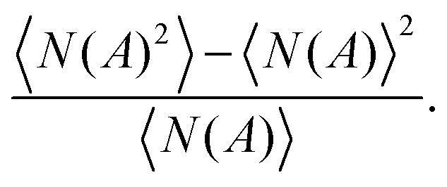
When reducing the shear rate, the microstructure changes and, depending on particle volume fraction and interparticle interactions, larger isolated clusters or even a 3D network form. In this case it is more relevant to quantify the heterogeneity of the microstructure. The number density fluctuations as a function of box size were used as a descriptor.57–59 The latter is defined as the integrated pair correlation function and is determined by placing boxes of different sizes on the image and counting the particles inside. Therefore, the number density variations are defined as the variance in the number of particles, N(A), calculated for a fixed box size of area A in different frames and normalized by the mean number of particles in that box:
 | (1) |
The boxes were placed randomly at 100 different positions for each frame. Boxes with a side length (d) ranging from one particle diameter (2a) to a maximum of 1/5 of the total image size were used. The number of frames chosen for a good averaging was such that considering additional frames would not change the result. Changes in the number density fluctuations correspond to gradients in the local density or heterogeneities in the structure, and the associated length scales can be identified as a characteristic length scale of the heterogeneous structure. Box sizes where the number density fluctuations become approximately constant indicate length scales on which the density is homogeneous. This measure is directly related to the compressibility of the suspension and equal to the low-q limit of the structure factor.60 To quantify the anisotropy of the images at relatively high shear rates, their FFT was calculated using Image-J.§61
Results and discussion
Matrix rheology
Experimental data for the steady-state viscosity η and stress ratios corresponding to the first and second normal stress differences, N1/σ21 and −N2/σ21, as a function of shear rate![[small gamma, Greek, dot above]](https://www.rsc.org/images/entities/i_char_e0a2.gif) are shown in Fig. 1 for the Newtonian and viscoelastic matrices. The matrix consisting of linear PDMS and cis-decalin behaves as a Newtonian fluid (N), with a constant viscosity as a function of shear rate. Instead, the matrix consisting of branched PDMS and cis-decalin behaves as a viscoelastic shear thinning fluid (VE) (Fig. 1), showing a decreasing viscosity as a function of shear rate. As expected, the Newtonian matrix did not show any normal stress difference, hence no stress ratio could be evaluated. Unlike the Newtonian matrix, at shear rates above 10 s−1 the viscoelastic matrix shows measurable first and second normal stress differences. A positive N1 results in a positive stress ratio whose value increases above 1 at 100 s−1, meaning that at high shear rates we enter into a relatively high Wi regime. As expected, the viscoelastic polymer matrix shows a positive N1 and a negative N2 wherein absolute modulus increases with the shear rate. The first normal stress difference, N1, measures the difference in normal stress between the flow and gradient directions, while the second normal stress difference, N2, measures the difference in normal stress between the gradient and vorticity directions.62,63 Physically, a positive N1 and negative N2 means that the elastic stresses are anisotropic, typical of a polymer matrix, and the stress tensor of the matrix is flow-oriented.
are shown in Fig. 1 for the Newtonian and viscoelastic matrices. The matrix consisting of linear PDMS and cis-decalin behaves as a Newtonian fluid (N), with a constant viscosity as a function of shear rate. Instead, the matrix consisting of branched PDMS and cis-decalin behaves as a viscoelastic shear thinning fluid (VE) (Fig. 1), showing a decreasing viscosity as a function of shear rate. As expected, the Newtonian matrix did not show any normal stress difference, hence no stress ratio could be evaluated. Unlike the Newtonian matrix, at shear rates above 10 s−1 the viscoelastic matrix shows measurable first and second normal stress differences. A positive N1 results in a positive stress ratio whose value increases above 1 at 100 s−1, meaning that at high shear rates we enter into a relatively high Wi regime. As expected, the viscoelastic polymer matrix shows a positive N1 and a negative N2 wherein absolute modulus increases with the shear rate. The first normal stress difference, N1, measures the difference in normal stress between the flow and gradient directions, while the second normal stress difference, N2, measures the difference in normal stress between the gradient and vorticity directions.62,63 Physically, a positive N1 and negative N2 means that the elastic stresses are anisotropic, typical of a polymer matrix, and the stress tensor of the matrix is flow-oriented.
 | ||
| Fig. 1 Rheological properties of the suspending fluids. Viscosity curves of the Newtonian and viscoelastic matrices (filled symbols), and stress ratios, N1/σ21 and −N2/σ21, of the viscoelastic matrix (open symbols). Both matrices consist of 84 wt% of PDMS, linear or branched, respectively, and 16 wt% of cis-decalin. | ||
Steady-state microstructures and stress contributions
The flow curve (shear stress versus shear rate) of the suspension is shown in Fig. 2(a) along with the flow curve of the matrix, which is plotted as a comparison only at high shear rates. This shows the typical behavior of an aggregated suspension with a yield stress and an increase of viscosity at higher shear rates, compared to the matrix viscosity. Dullaert and Mewis64 have used stress jumps to clarify how the non-Newtonian behaviour of the suspension finds its origin in the stress dependent microstructure, which changes from a percolating network with an essentially solid like response to a fluid system containing small dispersed aggregates at low volume fraction. The origin of these viscous and elastic stress contributions to the overall stress in such suspensions is described in the works of Doi et al.65 and Potanin and coworkers.66 To measure such stress jumps, a rheometer with a force rebalanced transducer (ARES G2) was used. The experimental protocol consists of a pre-shear step until steady state is reached at a certain initial value of shear rate,i, followed by a step down in shear rate to a final value of 0.0001 s−1, as explained in ref. 64 (an example can be found in Fig. S1 in the ESI†). The final shear rate chosen was not 0 s−1 but an almost-zero value due to some specific instrumental issues with drift at zero shear rate. The experimental response in the first 30 ms cannot be taken into account since it is related to the response of the mechanical and electronic components of the rheometer, even when signal filtering is reduced. The viscous and elastic contributions were calculated by performing a log-linear regression of the data between 30 ms and 70–100 ms and determining the intercept (an example can be found in Fig. S2 in the ESI†). After 100 ms the thixotropic recovery of the material starts interfering with the viscoelastic response of the material, setting the limit of the data range which can be used for the calculation of stress contributions.
 | ||
| Fig. 2 Steady state rheology and microstructure for suspensions with a Newtonian matrix. (a) Elastic and viscous contribution in a 10 vol% suspension in the linear PDMS–decalin matrix, measured performing stress jump experiments. Microstructures at (b) 0.025 s−1 (PeN = 95, BiN = 0.03), (c) 0.063 s−1 (PeN = 200, BiN = 0.07), (d) 0.25 s−1 (PeN = 950, BiN = 0.3), (e) 1 s−1 (PeN = 4000, BiN = 1.2), and (f) 20 s−1 (PeN = 75000, BiN = 24). All images have the same FOV, scale bar 30 μm. | ||
Stress jump experiments for a suspension of 10 vol% PMMA in the Newtonian matrix resulted in rate dependent viscous and elastic stresses as reported in Fig. 2a, along with the total stress response at steady state. These results are in line with the data on suspensions of fumed silica in paraffinic oil and poly(isobutylene) by Dullaert and Mewis,64 with the responses at low deformation rates being elastic in nature. Indeed from the stress jump measurements it results that at very low shear rates, 0.01 (PeN = 35, BiN = 0.01) up to 0.063 s−1 (PeN = 200, BiN = 0.07), the steady state shear stress, and hence the apparent yield stress of 5 Pa, is elastically-dominated. The microstructure was visualised by using the rheo-confocal setup, so that a qualitative relation with the stress contributions can be found. The corresponding microstructures at 0.025 (PeN = 95, BiN = 0.03) and 0.063 s−1 (PeN = 200, BiN = 0.07) are shown in Fig. 2b and c, respectively. At these shear rates the stress is elastic and it emerges from big particle clusters that interconnect. As the rate is increased the elastic stress component decreases, but the viscous (hydrodynamic) part of the stress starts to become dominant. Fig. 2d shows the structure at 0.25 s−1 (PeN = 950, BiN = 0.3) as the bonds between flocs are lost, and there are mostly large isolated clusters. Fig. 2a shows that at this point the viscous stress becomes higher than that of the elastic one. When going to intermediate shear rates like 1 s−1 (PeN = 4000, BiN = 1.2), the system enters a purely viscous region where elastic stresses tend to be zero and hydrodynamic stresses dominate. Therefore, the elastic stresses could not be detected anymore above 1 s−1. Fig. 2e shows that isolated clusters are the main microstructural units. In line with the literature,29,32–34 these flocs are getting smaller in size, compared to Fig. 2d, because they are subjected to higher Pe numbers. At relatively high shear rates, for instance at 20 s−1 (PeN = 75000, BiN = 24), flocs are broken down almost fully. Fig. 2f shows that, at these shear rates, the microstructure is made of small clusters of particles tumbling as a whole and aligning in the vorticity direction. In this region the stress is purely viscous as shown in Fig. 2a.
The same rheological and microstructural analysis was performed for 10 vol% PMMA dispersed in the viscoelastic matrix (Fig. 3). Also in this case at low shear rates, for instance at 0.025 s−1 (PeVE = 135, BiVE = 0.03), the stress is purely elastic and the viscous contribution is negligible. Fig. 3b shows the microstructure at such low shear rate, which from a first analysis appears to be very similar to the Newtonian case, with flocs of particles interconnected and probably forming a 3D spanning network. Increasing the shear rate up to 0.16 s−1 (PeVE = 850, BiVE = 0.17), the number of inter-floc bonds seems to decrease leading to a more heterogeneous microstructure consisting of big flocs and large voids, as shown in Fig. 3c. Here, at 0.16 s−1, the viscous contribution becomes comparable to the structural (elastic) one. When increasing the applied shear rate up to 0.4 s−1 (PeVE = 2000 and BiVE = 0.44), the plot in Fig. 3a shows how the suspension enters the region where the viscous contribution becomes dominant. The corresponding microstructure is shown in Fig. 3d, with flocs appearing more isolated and smaller in size. For the Newtonian matrix, a shear rate of 1 s−1 (PeN = 4000, BiN = 1.2) was enough to create a purely hydrodynamic stress. When particles are suspended in a viscoelastic matrix this is not unexpectedly different. Indeed, at 1 s−1 (PeVE = 5000 and BiVE = 1.1) in a viscoelastic matrix, the elastic contribution to the stress starts increasing again along with the shear rate. However, the elastic stress in this case is coming from the matrix and not from the particulate structure. Qualitatively, the aggregates do not differ much from the case of the suspension in the Newtonian matrix (Fig. 2e), with isolated relatively small flocs, however the stress is partially elastic whereas, in the Newtonian matrix, it was purely viscous. At 20 s−1 (PeVE = 80000, BiVE = 22), the formation of small clusters of particles oriented in the vorticity direction is also detected (Fig. 3f), but unlike the Newtonian case, here a measurable elastic stress is generated exclusively by stretching the polymer chains of the matrix (Fig. 3a). Overall, at such high shear rates the viscous stress is however still almost an order of magnitude higher, indicating that the hydrodynamic stress still dominates. The elastic and viscous contributions in the branched matrix fluid are shown in Fig. S3 in the ESI.†
 | ||
| Fig. 3 Steady state rheology and microstructure for suspensions with a viscoelastic matrix. (a) Elastic and viscous contribution in a 10 vol% suspension in the branched PDMS–decalin matrix, measured performing stress jump experiments. Microstructures at (b) 0.025 s−1 (PeVE = 135, BiVE = 0.03), (c) 0.16 s−1 (PeVE = 850, BiVE = 0.17), (d) 0.4 s−1 (PeVE = 2000, BiVE = 0.44), (e) 1 s−1 (PeVE = 5000, BiVE = 1.1), and (f) 20 s−1 (PeVE = 80000, BiVE = 22). All images have the same FOV, scale bar 30 μm. | ||
Cluster densification and rheological properties
When focusing the analysis on the suspension microstructure at high shear rates, for instance at 20 s−1 (the value at which the Pe numbers in the two suspensions are comparable), the formation of dense aggregates tumbling as a whole and some moderate alignment in the vorticity direction is observed in both cases, as expected for aggregated systems18,22 (Fig. 4). In Fig. 4 typical particle arrangements in the two different matrices at 20 s−1 (PeN = 75000, BiN = 24; PeVE = 80000, BiVE = 22) as well as the corresponding FFTs are shown. The denser clusters forming in the viscoelastic matrix seem to strongly orient in the vorticity direction (Fig. 4(b)). Indeed, by computing the Fourier transform of the images, at small wave vectors a more pronounced vorticity alignment in the power spectrum can be detected in a viscoelastic matrix, with a hint of a butterfly pattern. The FFT in Fig. 4 is averaged over a thousand frames. A detailed analysis of the aggregates by looking at the coordination number shows that at the same volume fraction and Pe, denser clusters are formed in a viscoelastic matrix, as evidenced from the shift of the coordination number distribution towards higher values shown in Fig. 5. This cluster densification can be rationalised based on the indirect effects of the normal stress differences and the resulting changes in the disturbance velocity fields around the particles.19–21 Every data point of the plot is averaged over around 4000 particles and the probability is normalised by the total number of particles so that a comparison of the two cases can be made. In the viscoelastic matrix, although the clusters seem to densify, the 2D average coordination number remains low (around 2.3). However, such a small average coordination number is derived from the relatively small average size of the clusters, with the bigger clusters consisting of approximately 10 particles.
 | ||
| Fig. 4 Extent of floc densification. Microstructures and 2D-FFTs showing cluster orientation at 20 s−1 (PeN = 75000, BiN = 24; PeVE = 80000, BiVE = 22) of (a) 10 vol% suspension in the Newtonian matrix and (b) 10 vol% suspension in the viscoelastic matrix. To guide the eyes, clusters are identified using different colours. | ||
 | ||
| Fig. 5 Coordination number distribution at high Pe. Analysis of the microstructure at 20 s−1 (PeN = 75000, BiN = 24; PeVE = 80000, BiVE = 22) for both suspensions of 10% particles in a Newtonian (blue square symbols) and viscoelastic matrix (red round symbols). | ||
Clusters and cluster size distributions can be derived by using the particle positions and distances obtained through confocal imaging. Based on cluster size distributions, an effective volume fraction can be calculated, which is 0.27 ± 0.02 for the suspension in the Newtonian matrix and 0.23 ± 0.02 in the viscoelastic one. The stress jump experiments of Fig. 2 and 3 showed that in both classes the hydrodynamic stress dominates at high Pe; therefore the effective volume fraction can be obtained from the relatively high shear viscosity as well. The effective volume fraction, ϕeff, can be calculated from:67
 | (2) |
This denser local aggregate structure is also reflected in subsequent network structures formed following preshear. If the shear rate is stepped down to a value of 0.025 s−1 (PeN = 95, BiN = 0.03; PeVE = 135, BiVE = 0.03), the number density fluctuations can be studied to assess sample heterogeneity. Fig. 6 shows that, at larger length scales, number density fluctuations are enhanced for particles suspended in a viscoelastic matrix, which indicates an increased compressibility and the existence of larger voids. While in classical depletion systems heterogeneities are shown up to length scales of 10 to 20 particle diameters at the most, when suspending particles in a polymer matrix, structures at length scales of 100 particle diameters are developing. Moreover, the analysis of the number density fluctuations suggests different cluster architectures forming in the two matrices at low shear rates. In particular, more open aggregates seem to develop in the Newtonian matrix. Therefore, even at low Pe numbers and negligible stress ratios more compact clusters and larger voids are forming in the viscoelastic matrix. These more compact flocs come from the preshear step performed at high shear rates. The cluster densification induced during preshear is consistent with the shear-induced microstructural evolution observed previously in other colloidal dispersions, such as carbon black suspensions,68–71 amongst others.
 | ||
| Fig. 6 Number density fluctuations as a function of the particle size (2a) normalized by the counting box size (d) at low Pe. Analysis of the microstructure at 0.025 s−1 (PeN = 95, BiN = 0.03; PeVE = 135, BiVE = 0.03) for both suspensions of 10% particles in Newtonian (blue lines) and viscoelastic matrices (red lines). | ||
Making stronger gels
The results in the previous sections, as in Fig. 5 and 6, showed that denser aggregates are formed in strongly sheared viscoelastic matrices. The density of the aggregates lowers the effective volume fraction as was inferred both from the high shear viscosity and the confocal images (Fig. 5). It can be expected that these denser network building blocks increase the percolation threshold when compared at overall volume fraction. On the other hand, recent work on colloidal gels48 has demonstrated that gel elasticity is controlled by the volume fraction of locally isostatic clusters, which can be expected to increase more strongly with volume fraction in the denser systems. Here, the change in percolation threshold and volume fraction dependency of gel elasticity are shown to be linked.To set a reproducible initial condition, a preshear step at 100 s−1 (PeN = 375000, BiN = 117; PeVE = 320000, BiVE = 110) was performed for the model suspensions of 10 vol% PMMA in both matrices, leading to the formation of denser building blocks in the viscoelastic matrix at high shear rates (Fig. 5). The build up of the gel microstructure was monitored for approximately 3 hours by applying amplitude oscillatory flow in the linear viscoelastic region and it is shown in Fig. 7(a). For the suspension in the Newtonian matrix, the loss modulus is initially higher than the storage one, and the values remain constant for a few minutes. Subsequently, the moduli start to evolve over time, with the G′ value initially lower than G′′, until they cross each other. Eventually, the storage modulus becomes higher than the loss modulus. A different picture emerges when a viscoelastic matrix is used as a suspending medium. Both moduli appear to level off already at the beginning of the recovery step and the loss modulus remains dominant even after 3 hours. An explanation for this lies in a change of the percolation limit. Indeed, the formation of denser clusters in the viscoelastic matrix results in a different number of single particles. In order to test whether the percolation limit really plays such a dominant role, the moduli evolution during the gel build up step was monitored at higher particle loadings as well.
 | ||
| Fig. 7 Time sweep following a strong preshear at 100 s−1 (PeN = 375000, BiN = 117; PeVE = 320000, BiVE = 110). (a) 10 vol% of PMMA–PHSA particles (executed at γ = 0.25%; 0.25 rad s−1) and (b) 40 vol% of PMMA–PHSA particles (executed at γ = 0.01%; 1 rad s−1). | ||
Fig. 7(b) reports the gel recovery step but for suspensions with a particle volume fraction of 40 vol%. Notice that, at this concentration, the preshear step was performed at a shear rate of 0.1 s−1 (PeN = 380, BiN = 0,12; PeVE = 535, BiVE = 0.11) only, due to the occurrence of shear fracture at higher shear rates. Already at the very beginning of this recovery test, the storage modulus is higher compared to the loss modulus, in both suspensions. At high particle content the storage modulus increases over time in both the Newtonian matrix and the viscoelastic one, following a power law relation. Another important outcome concerns the fact that, at higher concentrations, the storage modulus is greater when PMMA particles are dispersed in a viscoelastic matrix rather than a Newtonian fluid. This result suggests that when increasing the volume fraction, stronger gels can be formed by exploiting the viscoelastic shear densification. Unfortunately, these higher volume fractions could not be imaged sufficiently to provide a clear quantitative comparison.
A dynamic test has been performed at intermediate particle volume fractions as well. Fig. 8 displays the value of storage modulus, G′, reached after 3 hours of recovery as a function of volume fraction. Notice that the dash dot lines are just there to guide the eyes. The steady state value of the storage modulus seems to increase monotonically with the volume fraction, and with different slopes in the two matrices. Koumakis and Petekidis72 distinguished different behaviour at low and high ϕ. Here, at relatively low volume fractions for a cluster fluid (ϕ = 0.1), using a Newtonian rather than a viscoelastic matrix creates the strongest gels, as the distance to the percolation threshold is larger. However, increasing the filling volume fraction, in the existence region of a transient percolated network (0.1 < ϕ < 0.3), the moduli become more and more similar until a crossover point as the higher density for the clusters leads to a stronger dependency on volume fraction. Eventually, at high volume fractions when the material exhibits a solid-like response (ϕ = 0.4), as already seen before, viscoelasticity compacts the flocs and boosts the storage modulus.
 | ||
| Fig. 8 Values of the storage modulus reached after 3 hours as a function of volume fraction for both suspensions in Newtonian (blue square symbols) and viscoelastic matrices (red round symbols). | ||
The rheological properties of the fully developed gels also reflect this difference in the aggregate structure. Rheological properties can be used to characterize the gel structure, by using a fractal scaling theory.44 For fractal gels, Shih et al. defined two regimes, depending on whether links between different fractal flocs, the inter-floc links, are stronger or weaker than bonds within a floc, the intra-floc bonds. In both regimes, albeit with different expressions for the exponents, G′ increases with the volume fraction following a power law, which for fractal gels depends on the flocs fractal dimension Df:73
| G′ ∝ ϕf(Df) | (3) |
In the fractal regime, the fractal dimension should reflect the density of the aggregates in the different matrices and it was fitted based on the lowest volume fraction experimental data (Fig. S4 in the ESI†) using the model of Wu and Morbidelli45 (Section S3 in the ESI†). The gels made with presheared viscoelastic materials are more “brittle” and the moduli show a stronger dependency on volume fraction, consistent with the confocal observations of denser aggregates. Although not all gels belong to the fractal regime (too high volume fractions) it is helpful to look at the “effective” fractal dimension obtained from the analysis which is found to be Df = 2.3 for the suspension in Newtonian medium and Df = 2.6 for the suspension in the viscoelastic suspending medium. The lower fractal dimension for the suspension in the Newtonian matrix suggests that the more open aggregates compared to the ones in the viscoelastic matrix are retained in the final gel properties. Finally, the lower fractal dimension, and thus the formation of more open flocs, rationalizes the trend towards a lower percolation threshold in the Newtonian matrix, and therefore the different trends of moduli during recovery in the two matrices.
Conclusions
The viscoelasticity of the suspending matrix changes the local torque and pressure distribution around single particles or particle aggregates. For both a Newtonian and a viscoelastic matrix, the subsequent shear rate dependent microstructures in the flow-vorticity plane and the resulting rheological properties have been studied, by using of a homemade rheo-confocal setup. By performing stress jump experiments the elastic and viscous contributions to the total stress at steady state have been separated, revealing a complex interplay between particles and the viscoelastic matrix. At equal viscous strength (comparable Pe numbers) but different stress ratios, the microstructural analysis showed that denser clusters are developed in a viscoelastic matrix. Furthermore, from the evolution of the viscous stresses at high shear rates, cluster densification in a viscoelastic matrix could be inferred from a lowered effective volume fraction. When comparing gels at equal volume fraction, the cluster densification has two opposite effects for the structural recovery, on one hand the percolation threshold in the densified systems is increased, but on the other hand, the aggregate contributions once in a network are stronger. In viscoelastic media, processing gels at low volume fractions leads to weaker gels compared to particles at the same attraction strength in Newtonian media, but stronger gels are obtained for higher volume fractions. This adds medium viscoelasticity as a parameter to be considered when designing colloidal gels.Conflicts of interest
There are no conflicts to declare.Acknowledgements
PVP and RM acknowledge funding of the KU Leuven GOA/05/007 project. This project has received funding from the European Unions Horizon 2020 research and innovation programme under grant agreement no. 731019 (EUSMI).References
- C. Gallegos and J. Franco, Curr. Opin. Colloid Interface Sci., 1999, 4, 288–293 CrossRef CAS.
- L. A. Utracki and A. M. Jamieson, Polymer Physics: From Suspensions to Nanocomposites and Beyond, Wiley, 2010 Search PubMed.
- W. J. Stark, P. R. Stoessel, W. Wohlleben and A. Hafner, Chem. Soc. Rev., 2015, 44, 5793–5805 RSC.
- M. Mikolajek, A. Friederich, W. Bauer and J. R. Binder, Process Eng., 2015, 92, E25–E29 CrossRef.
- H. W. Kim, J. H. Lee, S. M. Park, M. H. Lee, I. W. Lee, H. S. Doh and H. J. Park, J. Food Sci., 2018, 83, 2923–2932 CrossRef CAS PubMed.
- D. Sunday, J. Ilavsky and D. L. Green, Macromolecules, 2012, 45, 4007–4011 CrossRef CAS.
- D. L. Green and J. Mewis, Langmuir, 2006, 22, 9546–9553 CrossRef CAS PubMed.
- M. Fuchs and K. S. Schweizer, Europhys. Lett., 2000, 51, 621 CrossRef CAS.
- J. B. Hooper and K. S. Schweizer, Macromolecules, 2005, 38, 8858–8869 CrossRef CAS.
- J. Michele, R. Pgitzold and R. Donis, Rheol. Acta, 1977, 16, 317–321 CrossRef CAS.
- D. J. Highgate, Nature, 1966, 211, 1390–1391 CrossRef CAS.
- D. J. Highgate and R. W. Whorlow, Rheol. Acta, 1969, 8, 142–151 CrossRef.
- A. Ponche and D. J. Dupuis, J. Non-Newtonian Fluid Mech., 2005, 127, 123–129 CrossRef CAS.
- M. K. Lyon, D. W. Mead, R. E. Elliott and L. G. Leal, J. Rheol., 2001, 45, 881–890 CrossRef CAS.
- R. Scirocco, J. Vermant and J. Mewis, J. Non-Newtonian Fluid Mech., 2004, 117, 183–192 CrossRef CAS.
- N. O. Jaensson, M. A. Hulsen and P. D. Anderson, J. Non-Newtonian Fluid Mech., 2015, 225, 70–85 CrossRef CAS.
- N. O. Jaensson, M. A. Hulsen and P. D. Anderson, J. Non-Newtonian Fluid Mech., 2016, 235, 125–142 CrossRef CAS.
- S. Van Loon, J. Fransaer, C. Clasen and J. Vermant, J. Rheol., 2014, 58, 237–254 CrossRef CAS.
- G. D'Avino, M. A. Hulsen, F. Snijkers, J. Vermant, F. Greco and P. L. Maffettone, J. Rheol., 2008, 52, 1331–1346 CrossRef.
- F. Snijkers, G. D'Avino, P. L. Maffettone, F. Greco, M. Hulsen and J. Vermant, J. Rheol., 2009, 53, 459–480 CrossRef CAS.
- F. Snijkers, G. D'Avino, P. L. Maffettone, F. Greco, M. A. Hulsen and J. Vermant, J. Non-Newtonian Fluid Mech., 2011, 166, 363–372 CrossRef CAS.
- R. Pasquino, F. Snijkers, N. Grizzuti and J. Vermant, Rheol. Acta, 2010, 49, 993–1001 CrossRef CAS.
- G. B. Jeffery, Proc. R. Soc. London, Ser. A, 1922, 102, 161 Search PubMed.
- D. Z. Gunes, R. Scirocco, J. Mewis and J. Vermant, J. Non-Newtonian Fluid Mech., 2008, 155, 39–50 CrossRef CAS.
- G. D'Avino and P. L. Maffettone, J. Non-Newtonian Fluid Mech., 2015, 215, 80–104 CrossRef.
- L. Leal, J. Fluid Mech., 1975, 69, 305–337 CrossRef.
- J. Moll, S. K. Kumar, F. Snijkers, D. Vlassopoulos, A. Rungta, B. C. Benicewicz, E. Gomez, J. Ilavsky and R. H. Colby, ACS Macro Lett., 2013, 2, 1051–1055 CrossRef CAS.
- J. Vermant and M. J. Solomon, J. Phys.: Condens. Matter, 2005, 17, R187–R216 CrossRef CAS.
- D. Tomi and D. Bagster, Chem. Eng. Sci., 1975, 30, 269–278 CrossRef CAS.
- T. G. M. Van de Ven and S. G. Mason, Colloid Polym. Sci., 1977, 255, 794–804 CrossRef CAS.
- T. G. M. Van de Ven and S. G. Mason, Colloid Polym. Sci., 1977, 255, 468–479 CrossRef CAS.
- P. Adler and P. Mills, J. Rheol., 1979, 23, 25–37 CrossRef.
- N. D. Vassileva, D. van den Ende, F. Mugele and J. Mellema, Langmuir, 2007, 23, 2352–2361 CrossRef CAS PubMed.
- K. Masschaele, J. Fransaer and J. Vermant, Soft Matter, 2011, 7, 7717–7726 RSC.
- P. Adler, J. Colloid Interface Sci., 1981, 81, 531–535 CrossRef CAS.
- S. Kao, R. Cox and S. Mason, Chem. Eng. Sci., 1977, 32, 1505–1515 CrossRef CAS.
- J. Bastide, L. Leibler and J. Prost, Macromolecules, 1990, 23, 1821–1825 CrossRef CAS.
- H. Verduin, B. J. de Gans and J. K. G. Dhont, Langmuir, 1996, 12, 2947–2955 CrossRef CAS.
- F. Pignon, A. Magnin and J.-M. Piau, Phys. Rev. Lett., 1997, 79, 4689–4692 CrossRef CAS.
- P. Varadan and M. J. Solomon, Langmuir, 2001, 17, 2918–2929 CrossRef CAS.
- J. Vermant, Curr. Opin. Colloid Interface Sci., 2001, 6, 489–495 CrossRef CAS.
- H. Hoekstra, J. Vermant, J. Mewis and G. G. Fuller, Langmuir, 2003, 19, 9134–9141 CrossRef CAS.
- Z. Varga and J. W. Swan, J. Rheol., 2018, 62, 405–418 CrossRef CAS.
- W.-H. Shih, W. Y. Shih, S.-I. Kim, J. Liu and I. A. Aksay, Phys. Rev. A: At., Mol., Opt. Phys., 1990, 42, 4772–4779 CrossRef CAS PubMed.
- H. Wu and M. Morbidelli, Langmuir, 2001, 17, 1030–1036 CrossRef CAS.
- A. Zaccone, H. Wu and E. Del Gado, Phys. Rev. Lett., 2009, 103, 208301 CrossRef PubMed.
- M. Laurati, G. Petekidis, K. Koumakis, F. Cardinaux, A. B. Schofield, J. M. Brader, M. Fuchs and S. U. Egelhaaf, J. Chem. Phys., 2009, 130, 134907 CrossRef CAS PubMed.
- K. A. Whitaker, Z. Varga, L. C. Hsiao, M. J. Solomon, J. W. Swan and E. M. Furst, Nat. Commun., 2019, 10, 2237 CrossRef PubMed.
- N. Koumakis, E. Moghimi, R. Besseling, W. C. Poon, J. F. Brady and G. Petekidis, Soft Matter, 2015, 11, 4640–4648 RSC.
- L. Palangetic, K. Feldman, R. Schaller, R. Kalt, W. R. Caseri and J. Vermant, Faraday Discuss., 2016, 191, 325–349 RSC.
- A. P. R. Eberle, N. Martys, L. Porcar, S. R. Kline, W. L. George, J. M. Kim, P. D. Butler and N. J. Wagner, Phys. Rev. E: Stat., Nonlinear, Soft Matter Phys., 2014, 89, 050302 CrossRef PubMed.
- N. S. Martys, M. Khalil, W. L. George, D. Lootens and P. Hébraud, Eur. Phys. J. E: Soft Matter Biol. Phys., 2012, 35, 20 CrossRef PubMed.
- T. Schweizer, Rheol. Acta, 2002, 41, 337–344 CrossRef CAS.
- F. Snijkers and D. Vlassopoulos, J. Rheol., 2011, 55, 1167–1186 CrossRef CAS.
- G. Colombo, R. Massaro, S. Coleman, J. Läuger, P. Van Puyvelde and J. Vermant, Korea-Aust. Rheol. J., 2019, 31, 229–240 CrossRef.
- J. Crocker and D. Grier, J. Colloid Interface Sci., 1996, 179, 298–310 CrossRef CAS.
- P. Varadan and M. J. Solomon, Langmuir, 2003, 19, 509–512 CrossRef CAS.
- P. Varadan and M. J. Solomon, J. Rheol., 2003, 47, 943–968 CrossRef CAS.
- K. Masschaele, J. Fransaer and J. Vermant, J. Rheol., 2009, 53, 1437–1460 CrossRef CAS.
- J. P. Hansen and I. R. McDonald, Theory of Simple Liquids, Elsevier, 1990 Search PubMed.
- C. A. Schneider, W. S. Rasband and K. W. Eliceiri, Nat. Methods, 2012, 9, 671–675 CrossRef CAS PubMed.
- J. Mewis and N. J. Wagner, Colloidal Suspension Rheology, Cambridge University Press, 2011 Search PubMed.
- C. W. Macosko, Rheology: Principles, Measurements, and Applications, John Wiley and Sons, 1994 Search PubMed.
- K. Dullaert and J. Mewis, J. Colloid Interface Sci., 2005, 287, 542–551 CrossRef CAS.
- M. Doi, J. Chem. Phys., 1983, 79, 5080–5087 CrossRef CAS.
- A. A. Potanin, R. Derooij, D. van den Ende and J. Mellema, J. Chem. Phys., 1995, 102, 5845–5853 CrossRef CAS.
- I. M. Krieger and T. J. Dougherty, Trans. Soc. Rheol., 1959, 3, 137–152 CAS.
- C. O. Osuji and D. A. Weitz, Soft Matter, 2008, 4, 1388–1392 RSC.
- C. O. Osuji, C. Kim and D. A. Weitz, Phys. Rev. E: Stat., Nonlinear, Soft Matter Phys., 2008, 77, 060402(R) CrossRef PubMed.
- A. S. Negi and C. O. Osuji, Rheol. Acta, 2009, 48, 871–881 CrossRef CAS.
- J. B. Hipp, J. J. Richards and N. J. Wagner, J. Rheol., 2019, 63, 423–436 CrossRef CAS.
- K. Koumakis and G. Petekidis, Soft Matter, 2010, 7, 2456–2470 RSC.
- B. B. Mandelbrot, Les objects fractals, Flammarion, Paris, 1975 Search PubMed.
Footnotes |
| † Electronic supplementary information (ESI) available. See DOI: 10.1039/c9sm02368b |
| ‡ The Weissenberg number is defined as the product of relaxation time and shear rate τ· which works well for single relaxation time models or fluids, while the stress ratio N1/σ gives rise to the balance between the normal stresses and shear stresses, hence it is a measure of fluid elasticity. |
| § The obtained 2D power spectrum is based on the implementation of the 2D Fast Hartley Transform (FHT) contributed by Arlo Reeves in image J https://imagej.nih.gov/ij/. |
| This journal is © The Royal Society of Chemistry 2020 |