
 Open Access Article
 This Open Access Article is licensed under a
 Creative Commons Attribution 3.0 Unported Licence
Experimental observation of boundary-driven oscillations in a reaction–diffusion–advection system†
Torsten
Eckstein‡
 ,
Estefania
Vidal-Henriquez‡
and
Azam
Gholami
*
,
Estefania
Vidal-Henriquez‡
and
Azam
Gholami
*
Max Planck Institute for Dynamics and Self-Organization, Göttingen, Germany. E-mail: azam.gholami@ds.mpg.de
First published on 30th March 2020
Abstract
Boundary-driven oscillations were numerically predicted to exist in a reaction–diffusion–advection system, namely in the signaling population of social amoeba D. discoideum. If deprived of nutrients, D. discoideum aggregates by producing cAMP waves at precisely timed intervals. In the presence of an advecting flow, holding the upstream boundary to a zero concentration of cAMP produces an instability that sends periodic wave trains downstream. This instability is expected to exist at lower degradation rates of cAMP and thus provides a mechanism for wave creation in phosphodiesterase deficient systems, such as PdsA− cells. Degradation of extracellular cAMP by the enzyme phosphodiesterase PdsA is fundamental to successfully producing waves, regulating the external cAMP gradient field and preventing the accumulation of cAMP. Using a flow-through microfluidic setup filled with PdsA− cells, we confirm experimentally that boundary-driven oscillations indeed exist. Above a minimum flow velocity, decaying waves are induced, with a decay length that increases with the imposed flow velocity. We performed extensive numerical simulations and showed that these waves have a boundary-driven origin, where the lack of cAMP in the upstream flow destabilizes the system. We explored the properties of these waves and the parameter region where they exist, finding good agreement with our experimental observations. These results provide experimental confirmation of the destabilizing effect of the upstream boundary in an otherwise stable reaction-diffusion system. We expect this mechanism to be relevant for wave creation in other oscillatory or excitable systems that are incapable of wave generation in the absence of flow.
Introduction
The social amoeba Dictyostelium discoideum (D. discoideum) is a paradigm model organism to study biological pattern formation and provides insights into the nature of cell–cell communication and emergent collective behavior.2–5D. discoideum cells lead a solitary life as long as the food supply is sufficient. Upon nutrient depletion, the cells start an aggregation process in which they gather in groups of around 104–106 amoebas and form multicellular structures known as fruiting bodies in order to survive.6,7 This aggregation process is governed by the chemotactic response of D. discoideum cells to outward propagating large-scale cAMP (cyclic adenosine monophosphate) waves that trigger oriented periodic movement of the cells towards the aggregation centers. These waves are generated by an interplay between random diffusion of cAMP in the extracellular medium and the ability of the cells both to receive the signal via cAMP receptors on the membrane of individual cells and to relay and amplify the signal by producing more cAMP. The cells crawl up the concentration gradient for a few minutes until the chemotactic response of the cells is adapted.8The limiting factor in signal amplification is the desensitization of cAMP receptors if they are persistently exposed to high concentrations of extracellular cAMP.9–11 To avoid receptor desensitization and to produce strong cAMP gradients, cells emit phosphodiesterases (PDEs) that degrade extracellular cAMP. Three extracellular PDEs have been characterized12 in D. discoideum: PDE1 (also called PdsA or PdeA), PDE4, and PDE7. All three types of PDEs have different dynamics, therefore becoming more relevant for cAMP degradation during different parts of the developmental program. During the early aggregation stage, PdsA is the dominant PDE, degrading the extracellular cAMP almost all by itself. The knockout mutant PdsA− does not produce PdsA and has been shown to be unable to produce cAMP waves, and thus the cells fail to aggregate.13 Rescue of this cell type was reported by adding PDE to the cell solution, which allowed for normal aggregation.13 Moreover, it has been shown that PdsA− amoebas show oscillations in the concentration of intracellular cAMP if subjected to a fresh buffer flow that carries extracellular cAMP away,14 suggesting that external flow can replace the role of PDE.
In their natural habitat, D. discoideum cells are exposed to external flows, which can significantly influence the wave generation process.15 Previously, we had numerically predicted the existence of a convective instability induced by the influx of cAMP-free buffer through a colony of signaling amoebas.1,16 In such a system, it is of utmost importance what kind of chemicals get injected into the system with the advecting flow. In the numerical simulations, this is equivalent to what boundary conditions are used in the upstream edge of the system. In the case where there are no cells upstream, the flow would be free of cAMP and can act as a destabilizing agent. We have shown that holding the upstream boundary to a zero concentration of cAMP produces an instability that periodically sends wave trains downstream. The wave generation mechanism works by first advecting the cAMP downstream, thus depleting the upstream area of cAMP. This low concentration of the chemoattractant destabilizes the cells close to the upstream boundary, which react by releasing a pulse of cAMP. This instability, known as boundary-driven oscillations,1 exists at lower degradation rates than the oscillatory regime and thus provides a mechanism for wave creation in phosphodiesterase-deficient systems, such as PdsA− cells.
In this work, we present experimental evidence of the existence of boundary-driven oscillations (BDOs), which can be observed in a microfluidic setup filled with starving PdsA− cells. Note that the imposed flow is not strong enough to detach the cells from the substrate and the cAMP produced by the cells is advected downstream. Interestingly, at small flow velocities, we observe decaying cAMP waves that do not fill the whole length of the channel, with a decay length that grows with the advecting flow velocity. Our extensive numerical simulations confirm a similar trend in the decay length of the waves as the flow is increased. We also quantified the period of these boundary-driven waves, measuring high wave periods (∼20 min) at small advective flows, which decrease with the imposed flow velocity, approaching the natural period of 6 min at flow velocities larger than 0.6 mm min−1. Interestingly, once the flow is switched off, the cells located upstream of the microfluidic channel (that have experienced BDOs) continue to produce cAMP waves similar to wild type cells, but with a much larger wave period of around 12 min. These amoebas are able to aggregate normally, rescuing the aggregation phenotype. However, cells downstream of the channel located outside the penetration depth of BDOs fail to aggregate once the flow is switched off. Thus, at high flow velocities where the BDOs penetrate the whole length of the channel, all the cells in the channel were rescued. We observed a similar effect when we used WT cells at the upstream area of the channel. The cAMP waves generated by WT cells penetrate gradually throughout the population of PdsA− cells, filling the whole length of the microfluidic channel with time.
Materials and methods
Cell culture
All experiments were performed with D. discoideum UK5 cells, denoted as PdsA− (Dicty Stock Center, Chicago, IL, USA). Cells were grown in HL-5 medium (35.5 g of Formedium powder from Formedium Ltd, Norfolk, England, per liter of double-distilled water, autoclaved and filtered) at 22 °C on polystyrene Petri dishes (TC Dish 100, Sarsted, Nümbrecht Germany) and harvested when they became confluent. Before the experiments, the cells were centrifuged and washed two times with phosphate buffer (2 g of KH2PO4 and 0.36 g of Na2HPO4·H2O per liter at pH 6.0, and autoclaved, both from Merck, Darmstadt, Germany). The cells were then resuspended in 200 μl of phosphate buffer. The cell density was determined using a hemocytometer (Neubauer Zählkammer, VWR, Darmstadt, Germany), diluted to 5 × 10⁷ cells per ml of phosphate buffer and injected into the microfluidic channel.Microfluidics
The microfluidic devices were fabricated by means of standard soft lithography17 methods. A silicon wafer was coated with a 100 μm photoresist layer (SU-8 100, Micro Resist Technology GmbH, Berlin, Germany) and patterned by photolithography to obtain a structured master wafer. The channels are 2 mm wide, 50 mm long, and 103 ± 2 μm high. Polydimethylsiloxane (PDMS, 10![[thin space (1/6-em)]](https://www.rsc.org/images/entities/char_2009.gif) :1 mixture with curing agent, Sylgard 184, Dow Corning GmbH, Wiesbaden, Germany) was poured onto the wafer and cured for 1 h at 75 °C. To produce the microfluidic device, a PDMS block containing the macro-channels was cut out, and two inlets (7 mm and 0.75 mm in diameter) were punched through the PDMS at opposite ends of the channel with the help of PDMS punchers (Harris Uni-Core-7.00 and Harris Uni-Core-0.75, Sigma-Aldrich, St. Louis, MO, USA). Afterwards, a glass microscope slide (76 × 26 mm, VWR, Darmstadt, Germany) was sealed to the PDMS block following a 20–30 s treatment in air plasma (PDC 002, Harrick Plasma, Ithaca, USA) to close the macro-channels. The large inlet (7 mm diameter) was used as a liquid reservoir filled with phosphate buffer and from the other side, phosphate buffer was sucked out using a high precision syringe pump (PHD 2000 Infuse/Withdraw Syringe Pump from Harvard Apparatus, Holliston, USA, combined with gas-tight glass syringes from Hamilton, Reno, USA) at constant buffer flow rates.
:1 mixture with curing agent, Sylgard 184, Dow Corning GmbH, Wiesbaden, Germany) was poured onto the wafer and cured for 1 h at 75 °C. To produce the microfluidic device, a PDMS block containing the macro-channels was cut out, and two inlets (7 mm and 0.75 mm in diameter) were punched through the PDMS at opposite ends of the channel with the help of PDMS punchers (Harris Uni-Core-7.00 and Harris Uni-Core-0.75, Sigma-Aldrich, St. Louis, MO, USA). Afterwards, a glass microscope slide (76 × 26 mm, VWR, Darmstadt, Germany) was sealed to the PDMS block following a 20–30 s treatment in air plasma (PDC 002, Harrick Plasma, Ithaca, USA) to close the macro-channels. The large inlet (7 mm diameter) was used as a liquid reservoir filled with phosphate buffer and from the other side, phosphate buffer was sucked out using a high precision syringe pump (PHD 2000 Infuse/Withdraw Syringe Pump from Harvard Apparatus, Holliston, USA, combined with gas-tight glass syringes from Hamilton, Reno, USA) at constant buffer flow rates.
Image acquisition and analysis
We used a dark-field setup consisting of a monochrome 12-bit CCD camera (QIClick-F-M-12, QImaging, Surrey, Canada), a telecentric lens (0.16X SilverTL Telecentric Lens, Edmund Optics Inc, Barrington, NJ, USA) and a ring light source (Advanced Illumination, Rochester, VT, USA). The camera was controlled with an image capture program (Micro-Manager18) and it recorded images every 20 seconds. We processed the dark-field videos by first subtracting the intensity trend of each pixel to normalize the signal in time. Next, we did spatial band-pass filtering to suppress structures bigger than 3.5 mm and smaller than 0.294 mm. Finally, we used the Hilbert transform19 to calculate the phase of each pixel, thus obtaining the phase maps.Numerical simulations
The Martiel–Goldbeter model20 is a reaction-diffusion model proposed in 1987 to describe pattern formation in D. discoideum and has been successfully used to describe spiral formation,3,21 wave advection,22 spontaneous center formation,23 and cell streaming.24 Changing the parameters in the model allows us to describe the system at different points during the starvation process or with knocked-out genes. To describe PdsA− cells, then, we use this model with a very low cAMP degradation rate.Numerical simulations of the Martiel–Goldbeter model20 to describe cAMP production and relay in D. discoideum were performed and compared with experimental results. The relay process starts when the cells detect the presence of cAMP in the extracellular media through the receptors located on the cell membrane. After binding with cAMP, the receptors change to a phosphorylated or inactive state, in which they have a lower probability of binding with cAMP. After some relaxation time, the receptors go back to their active state. The binding of the receptors with cAMP triggers a series of reactions inside the cell that culminate with the production of cAMP and the cells' motion against the wave direction. The produced cAMP is degraded into AMP by the intracellular phosphodiesterase and transported passively to the extracellular media. Finally, once outside of the cells, the cAMP is free to diffuse and is degraded by the action of phosphodiesterase in the extracellular media. This is the type of phosphodiesterase that PdsA− cells do not produce.
The equations are
 | (1) |
All used parameters are indicated in Table 1, and were kept fixed with the exception of σ (proportional to the production rate) and ke (degradation rate), which were used to explore the parameter space. To reproduce the signaling process in PdsA− cells, ke was kept low, ke ≪ 1 min−1, compared to simulations of wild type cells where ke ≈ 5–12 min−1.3,20,21
| c = 10 | h = 5 | k 1 = 0.09 min−1 |
| κ = 18.5 | α = 3 | k i = 1.7 min−1 |
| k t = 0.9 min−1 | ![[script L]](https://www.rsc.org/images/entities/char_e144.gif) 1 = 10 1 = 10 |
2 = 0.005 |
| q = 4000 | λ 1 = 10−4 | λ 2 = 0.2575 |
| D = 0.024 mm2 min−1 |
Numerical simulations were performed using finite differences with a 3 point Laplacian in 1-D and 5 point one in 2-D for space discretization and a Runge–Kutta scheme with an adaptative time step25 for the time evolution. A nonlinear discretization of the advection operator was used to ensure positivity of the cAMP concentration γ following the work of Koren.26 To account for the injection of buffer without cAMP, an absorbing boundary condition was used, that is, the value of γ was fixed at zero at the upstream boundary, γ(x = 0,t) = 0. At the downstream boundary, no-flux (∂xγ(x = L,t) = 0) boundary conditions were used. For a detailed analysis of the effects of advection in this setup filled with WT cells, refer to our previous works.1,22
Results
A fresh cAMP-free buffer flow can substitute PdsA− activity
In a population of starving D. discoideum cells, the level of extracellular cAMP is controlled by the activity of the enzyme adenylyl cyclase (ACA), which catalyzes the reaction in which cAMP is produced, and phosphodiesterase, which degrades cAMP. It is believed that PdsA, by degrading extracellular cAMP, plays an important role in regulating chemotaxis by establishing cAMP gradients during the streaming process. Upon starvation, PdsA− cells fail to produce cAMP waves and thus cannot aggregate. However, in our experiments with flow-through microfluidic channels, we observe that an external flow can effectively play the role of PdsA by removing the extracellular cAMP. Thereby, cAMP waves are recovered and the aggregation process is rescued.We observe boundary-driven waves in a population of PdsA− cells if they experience the external flow for at least three hours. The minimum imposed flow velocity needed to recover cAMP waves in our experiments was Vf ≥ 0.3 mm min−1. At velocities below 0.3 mm min−1, we did not observe any waves even during our long-run experiments where buffer was flowing through the channel for more than 10 hours. Fig. 1a–c shows examples of boundary-driven waves at low, moderate and high imposed flow velocities, respectively. In all of our experiments, the cAMP waves develop within three hours of imposing the flow. While the waves at Vf = 0.3 mm min−1 decay quickly as they initiate at the upstream end of the channel and never successfully propagate throughout the channel, waves at Vf = 0.7 mm min−1 are eventually able to penetrate and travel along the whole length of the channel. Full penetration of the waves in the channel at moderate flow speeds occurs within the time scale of three hours and the transition from partial to full penetration is fairly sharp. Interestingly, at the high flow speed of Vf = 1.5 mm min−1, once the waves develop upstream, they are able to propagate downstream throughout the channel almost immediately. We systematically measured the decay length of the waves as we increased the imposed flow velocity and found that it grows with the advective flow. Fig. 2a–d summarizes properties of these boundary-driven waves in terms of their wave velocity, decay length, period, and wavelength. Below, we consider different flow regimes and discuss wave properties in detail.
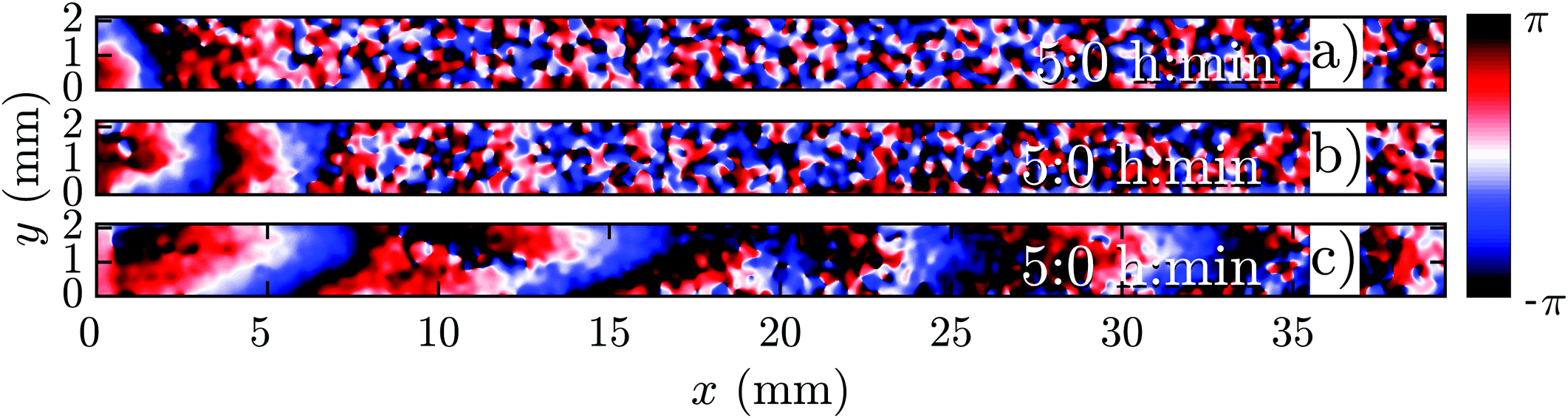 | ||
| Fig. 1 Phase map of boundary-driven waves in a population of PdsA− cells at (a) a low flow speed of Vf = 0.3 mm min−1, (b) a moderate flow speed of Vf = 0.7 mm min−1 and (c) a high flow speed of Vf = 1.5 mm min−1. While the waves in (a and b) are almost planar and decay along the channel, the waves in (c) are parabolic and fill the whole length of the channel (see Movies S1–S3, ESI†). Timestamps show the time since the flow was turned on. | ||
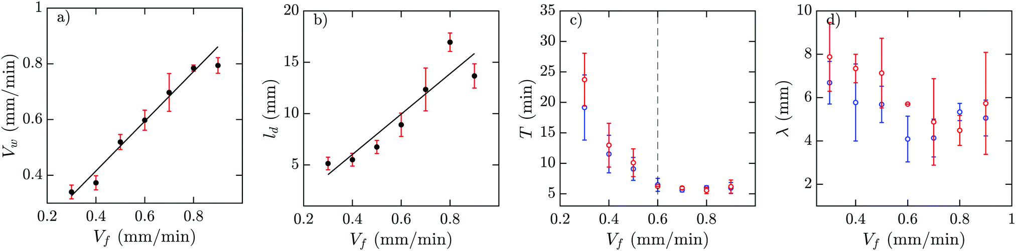 | ||
| Fig. 2 Experimental characterization of boundary-driven waves relayed by PdsA− cells when subjected to a flow of cAMP-free buffer. (a) Wave velocity Vw, (b) wave decay length ld, (c) the period T, and (d) the wavelength λ as a function of the imposed flow velocity Vf. Solid black lines in (a and b) represent a linear least-squares fit to the data. Blue and red data points in (c and d) are from the early and late regimes of the experiments. | ||
A. Waves at low flow velocities
The development of boundary-driven waves at the low flow velocity of Vf = 0.3 is shown in Fig. 3 (see Movie S1, ESI†). A wave front initiates at the upstream boundary of the channel and decays quickly over a length scale of ∼5 mm. Over time, the waves successfully travel a longer distance (∼10 mm) before dying out. We define a characteristic length ld, which corresponds to the length that a wave travels inside the channel before its amplitude is lower than 10% of its maximum amplitude. This length scale grows with the applied flow speed, meaning that the waves reach further downstream in the channel at higher flow speeds. Based on the decay length of the waves at a given flow velocity, we define an early regime and a late regime. During the early regime, the waves decay after a shorter length than during the late regime. Therefore, we systematically measure the wave period and the wavelength corresponding to each regime separately, as shown in Fig. 2c and d.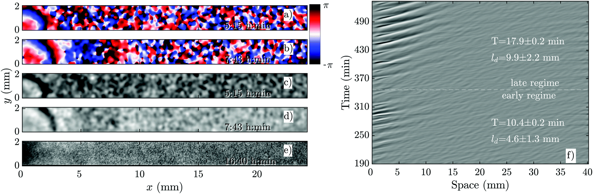 | ||
| Fig. 3 Overview of an experiment at a low flow speed of Vf = 0.3 mm min−1 (see Movie S1, ESI†). (a and b) Phase images extracted from processed images in (c and d). (a and c) Show waves during the early regime that decay immediately upon entering the channel. (b and d) Show waves during the late regime, which move slightly farther along the channel before decaying. (e) Shows that the cells do not aggregate even at the end of the experiment. (f) Shows part of the space–time plot of this experiment. Timestamps denote time since start of the experiment. | ||
An interesting feature of the waves developed in the flow range of 0.3 ≤ Vf ≤ 0.6 is their large period. We observed periods as large as 20–25 min for Vf = 0.3 mm min−1, decreasing to 10–15 min at Vf = 0.4 mm min−1 and approaching the normal period of 6 min at Vf = 0.6 mm min−1 (see Fig. 2c). It is plausible that at flow velocities larger than 0.6 mm min−1, the period of the waves is set by the random firing of the cells and not anymore by BDOs. This hypothesis was confirmed by our numerical simulations. Considering the wavelength of boundary-driven waves, for Vf ≥ 0.6 mm min−1, since the wave period is almost constant (∼6 min), mean wavelength increases from 3.5 mm to around 5.5 mm as Vf increases from 0.6 to 0.9 mm min−1. However, for Vf < 0.6 mm min−1, while the period decreases and imposed flow increases from 0.3 mm min−1 to 0.6 mm min−1, mean wavelength does not change significantly. Finally, the aggregation pattern of the cells in the presence of boundary-driven waves for Vf = 0.3 mm min−1 is shown Fig. 3e. It seems that cells even at the upstream part of the channel that were exposed to boundary-driven waves fail to aggregate. We believe that this is due to the fact that the amplitude of the boundary-driven waves at low flow speeds is not strong enough to trigger aggregation of the cells. The minimum flow speed needed in our experiments to rescue aggregation of the cells was 0.6 mm min−1. Note that this velocity coincides with the velocity at which the period of boundary-driven waves sets to the natural period of 6 min (see the dashed line in Fig. 2c).
B. Waves at moderate flow velocities
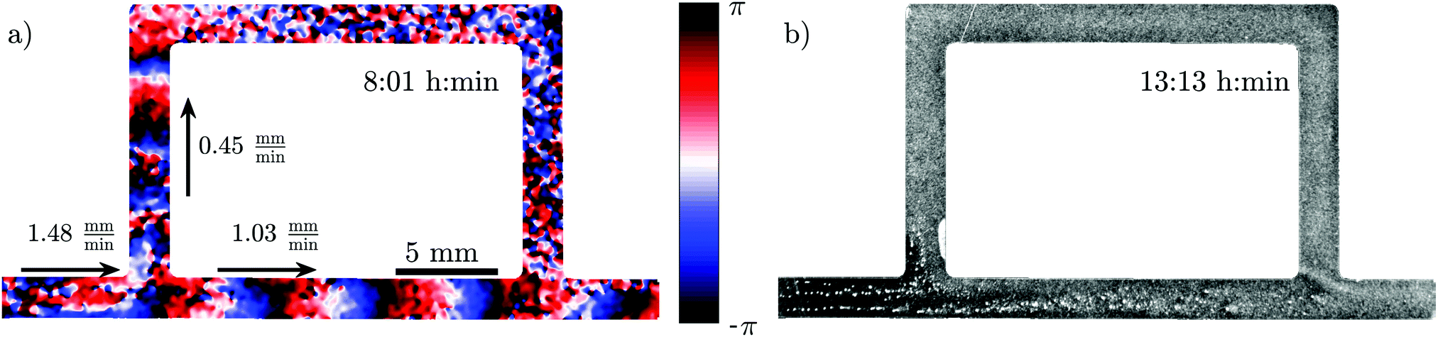
As we increase the flow velocity, in the range of 0.6 mm min−1 ≤ Vf ≤ 1 mm min−1, waves behave differently. Although in the early phase, they penetrate only in a part of the channel (Fig. 4a and c), in the late phase, they successfully propagate throughout the channel (Fig. 4b and d). Moreover, the waves are stronger in amplitude and have the normal period of 6 min, similar to the period of the flow-driven waves in WT cells.15,22 Regarding the aggregation pattern, we observe clusters of cells mostly in the upper part of the channel, confirming that aggregation is partially rescued. We also performed bright-field measurements to look closely at the aggregation of PdsA− cells in the presence of flow (Vf = 1 mm min−1). Fig. 5 shows that rescue of the cells is more successful at the upstream end of the channel where the boundary-driven waves penetrate initially and have a larger amplitude (see Movie S4, ESI†). Further downstream, the amplitude of the waves decays and is not strong enough to rescue the cells. At higher flow speed, aggregation clusters cover a larger portion of the channel. We emphasize that cells do not show aggregation clusters if the flow is stopped before they start producing boundary-driven waves.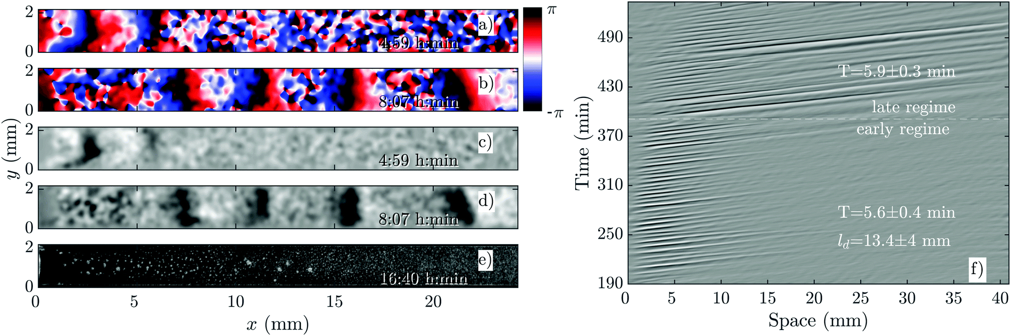 | ||
| Fig. 4 Overview of an experiment at a medium flow speed of Vf = 0.7 mm min−1 (see Movie S2, ESI†). (a and b) Phase images extracted from processed images in (c and d). (a and c) Show waves during the early regime that decay quickly along the channel. (b and d) Show waves during the late regime, which fill the entire channel. (e) Shows aggregation at the end of the experiment. (f) Shows a part of the space–time plot of this experiment. Timestamp denotes time since start of the experiment. | ||
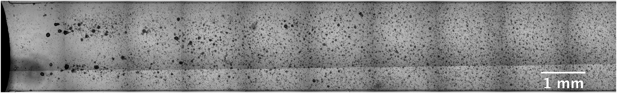 | ||
| Fig. 5 A bright-field image showing aggregation of cells in a flow-through channel (see Movie S4, ESI†). Images are taken at 4× magnification at different parts of the channel and stitched together. Note that at the upstream part of the channel, we have a reservoir filled with buffer, which is free of the cells and cAMP. The channel width is 2 mm. | ||
To examine the effect of different imposed flow velocities in a single experiment, we constructed a channel with a sidearm, as shown in Fig. 6. Since the length of the sidearm is about three times the length of the direct channel, the flow in this channel is about 2.2 times slower. This means that a direct comparison of the behavior at different flow speeds is possible in one experiment. As expected, the waves in the direct channel penetrate further down and are stronger than the ones in the sidearm, as shown in Fig. 6a and Movie S5 (ESI†). Similar to flow-driven waves in WT cells,22 the width of the wave fronts is larger in the straight part of the channel in comparison to the waves in the sidearm. Finally, the spatial extent of the waves affects the aggregation in the two channel parts. While the cells in the main channel aggregate quite well, there is a little aggregation in the sidearm where the spatial extension of the waves is shorter (see Fig. 6b). Note that further downstream, the aggregation process appears weaker compared to the upstream, which we believe is related to the wave amplitude that decays as it propagates along the channel.
 | ||
| Fig. 6 Experiment in a channel with a sidearm, which has a lower flow speed than the straight part of the channel (see Movie S5, ESI†). (a) Phase map of the developed boundary-driven waves and (b) the corresponding aggregation pattern at the later times. Note the different spatial extension of the waves in both parts of the channel, which is the important factor in deciding if the aggregation phenotype will be rescued or not. | ||
C. Waves at high flow velocities
If the imposed flow velocity is increased even further, Vf ≥ 1 mm min−1, the so-called early phase disappears. This means that once the boundary-driven waves initiate at the upstream part, they propagate through the entire length of the channel. Fig. 7 shows an experiment at Vf = 1.5 mm min−1. The waves have the normal period of 6 min and wave fronts are more elongated in comparison to small flow experiments, which is similar to flow-driven waves at high speeds described previously for WT cells.22 Cells over the entire length of the channel are rescued and successfully aggregate (see Fig. 7e and Movie S3, ESI†).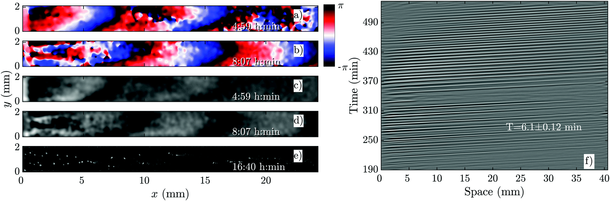 | ||
| Fig. 7 Boundary-driven waves at Vf = 1.5 mm min−1 (see Movie S3, ESI†). (a and b) Phase maps extracted from processed images in (c and d). (e) Cells over the entire length of the channel are rescued and aggregate normally. (f) Space–time plot of the waves showing that once the waves develop after three hours of flow, they travel through the entire channel. Timestamps denote time since the flow was applied. | ||
Rescue of PdsA− cells by flow
Another interesting observation in our flow experiments with PdsA− cells was the rescue of pattern formation once the flow was switched off. We exposed the cells to a minimum flow velocity of Vf = 0.6 mm min−1 and let the boundary-driven waves develop and propagate for a minimum time of one hour before we switched off the flow. Interestingly, we observed that in less than 90 min, wave centers developed spontaneously and relayed through the population. This occurred again at the upstream parts of the channel that were exposed to boundary-driven waves (see Fig. 8 and Movie S6, ESI†). The period of the spontaneous waves was significantly higher than the ones produced by wild type cells (16–24 min compared to 4–6 min in wild type cells). The wave velocity was measured to be 0.263 ± 0.006 mm min−1, which is comparable to the wave speed of 0.35 mm min−1 in wild type cells. A systematic measurement of wavelength, period and propagation velocity of the spontaneous waves is presented in Fig. 8b and c. In a single experiment, we measured a wide range of wave periods varying from 15 min (as they appear) to 25 min at later times. This is shown in Fig. 8b.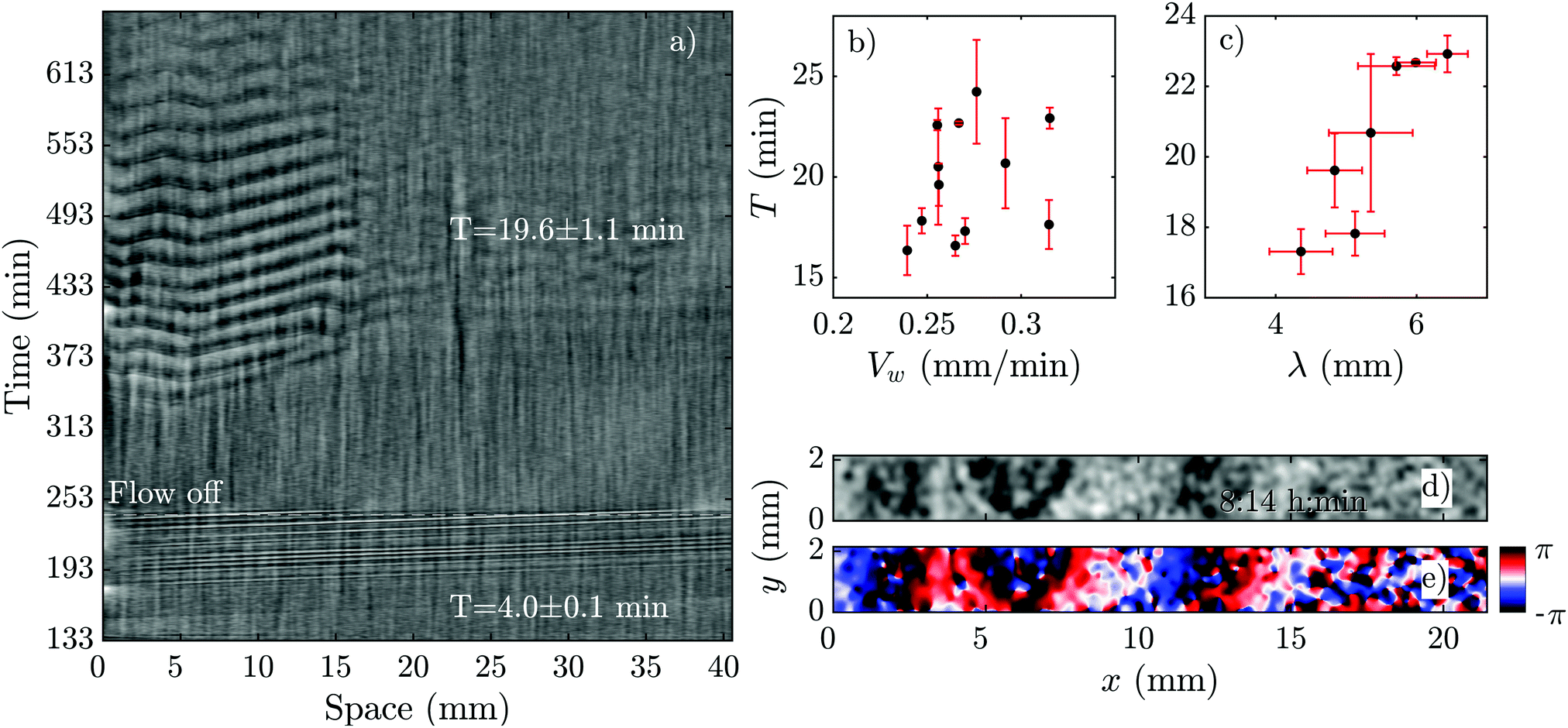 | ||
| Fig. 8 Pattern formation of PdsA− cells after the flow was switched off. (a) Space–time plot of an experiment at an imposed flow of Vf = 2 mm min−1. The flow was turned off after 240 min (see Movie S6, ESI†). (b) Period T and (c) wavelength λ of spontaneous waves (appearing in the flow-off regime) plotted as a function of wave velocity Vw. For these measurements, a set of different experiments at various flow velocities was used where the flow was switched off at different time points. (d) Processed dark-field image and (e) the corresponding phase map showing the initiation of a wave at the upstream part of a channel after the flow of Vf = 2 mm min−1 has been switched off. The corresponding space–time plot of this experiment is shown in part (a). Timestamps show the time since the flow was switched on. | ||
Based on these results, we explored the minimum time PdsA− cells need to be subjected to flow, such that they show spontaneous pattern formation once the flow is switched off. We found that the cells show spontaneous pattern formation, even if the population experienced the passage of very few boundary-driven waves before the flow was switched off. Fig. 9a shows an example where the flow of Vf = 2 mm min−1 was turned off once 1–2 pulses of boundary-driven waves passed through the channel. The cAMP waves form spontaneously at t ∼ 360 min only at the upstream part of the channel. Interestingly, at a flow speed of Vf = 5 mm min−1 and when we allowed boundary-driven waves to persist for about 2 hours, once we switched off the flow, the spontaneous waves appeared almost immediately again at t ∼ 360 min. Since the flow-driven waves penetrate throughout the channel, the recovered spontaneous waves are also observed over the entire length of the channel (see Movies S7 and S8, ESI†).
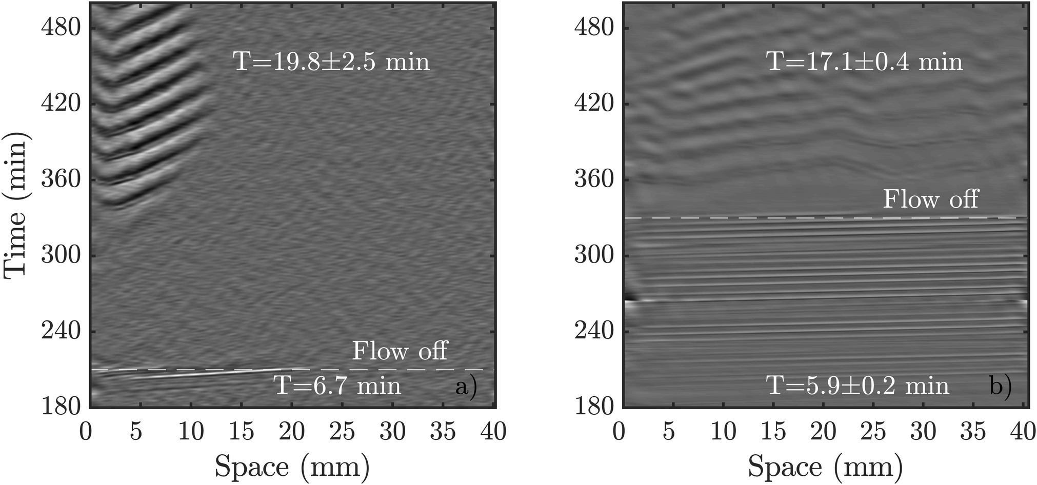 | ||
| Fig. 9 Comparison of spontaneous pattern formation once the flow is switched off. (a) Flow of Vf = 2 mm min−1 was switched off shortly after boundary-driven waves were observed. cAMP waves spontaneously appear at 360 min (see Movie S7, ESI†). (b) A higher flow velocity of Vf = 5 mm min−1 triggered boundary-driven waves that propagated through the population for more than two hours before the flow was turned off. The spontaneous waves appeared almost immediately (see Movie S8, ESI†). | ||
Rescue of PdsA− cells with Wild Type cells
As we mentioned above, pattern formation in PdsA− cells is impaired because of the lack of cAMP degradation. Therefore, we tried rescuing the cells by using the PdsA produced by Ax2 cells. To do this, we injected PdsA− cells into a channel and filled the reservoir of the channel with Ax2 cells. This reservoir is located upstream from the channel, and is where the fluid accumulates before flowing through the channel. Thus, the cell types were not mixed, but the buffer that flowed through the channel was preconditioned by its exposure to the Ax2 cells. We find that the behavior of this system depends strongly on the initial starvation time of the Ax2 cells used. In the case of using Ax2 cells without previous starvation, there is again no pattern formation for the first three hours of flow. Nevertheless, when waves emerge, they do not decay along the channel, but instead fill the channel immediately for all flow speeds studied. However, if we use Ax2 cells that were initially starved for 4 hours, we find that pattern formation is observed immediately after the flow is switched on. Initially, the waves decay rather quickly, but the decay length increases exponentially over time until the whole channel is filled, see Fig. 10a and Movie S9 (ESI†). The rate at which the decay length increases depends on the imposed flow velocity, filling the whole channel more quickly for higher advecting flows (see Fig. 10b).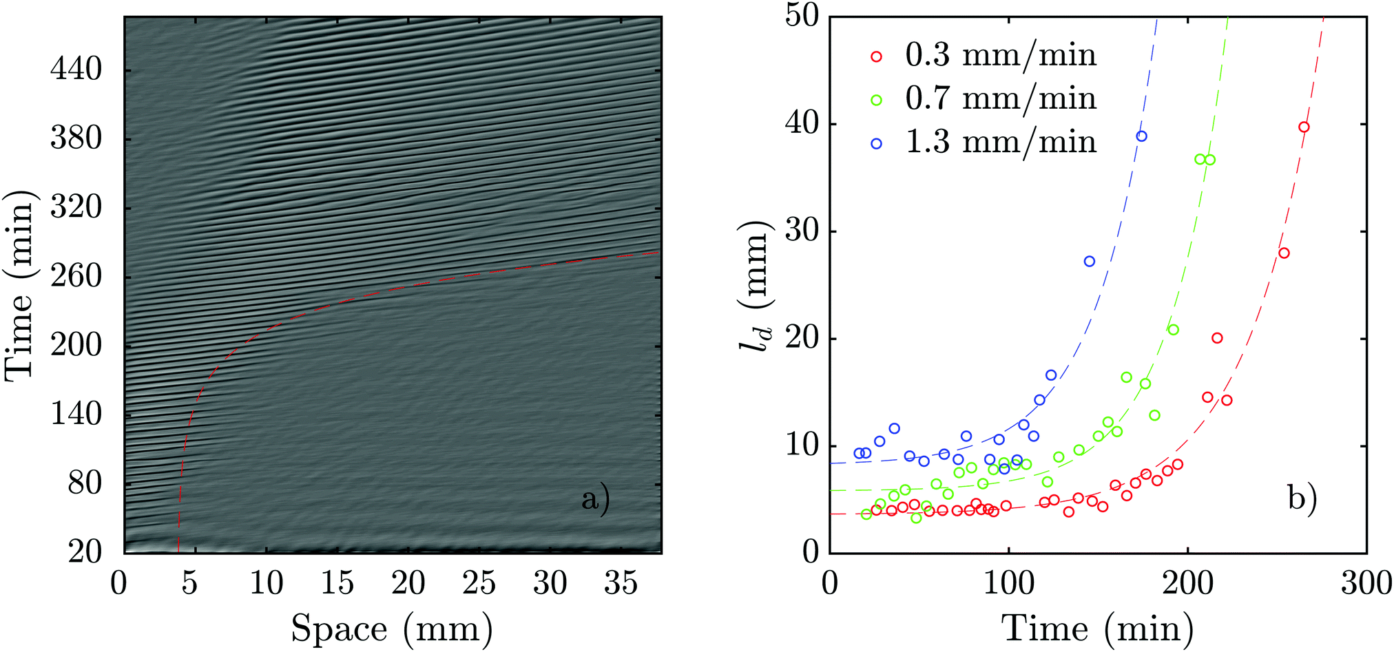 | ||
| Fig. 10 Flow-driven waves in experiments consisting of a channel filled with PdsA− cells while the reservoir was filled with Ax2 cells starved initially under agitation for 4 hours (see Movie S9, ESI†). (a) An exemplary space–time plot at Vf = 0.7 mm min−1 with a wave period of 6.2 ± 0.3 min. The red dashed line illustrates the change of decay length over time (see Movie S9, ESI†). In (b), the decay length is plotted vs. experiment time for different flow speeds. Dashed lines show least-squares fits of exponential functions to the data of the same color. For each data set, a function of the form f(x) = a·exp(b·x) + c was used. The fitting values are: a0.3 = 0.0474 mm, b0.3 = 0.0250 min−1, and c0.3 = 3.6374 mm, a0.7 = 0.0396 mm, b0.7 = 0.0316 min−1, and c0.7 = 5.8376 mm, and a1.3 = 0.1636 mm, b1.3 = 0.0303 min−1, and c1.3 = 8.2406 mm, respectively. | ||
Numerical simulations of PdsA− cells
We performed numerical simulations of the three-component MG model (eqn (1)) at different flow speeds. We selected σ and ke as control parameters since they account for the production and degradation of extracellular cAMP, respectively. Depending on these two parameters, this system can have stable, bistable and convectively unstable (CU) regimes, as shown in the phase diagram in Fig. 11a. We fixed parameters σ and ke to be in the stable regime of the phase diagram where the boundary-driven oscillations exist. Note that BDOs exist in the CU regime too, where we have shown1 that holding the upstream boundary to a zero concentration of cAMP produces an instability that sends periodic wave trains downstream. The wave generation mechanism works by first advecting the cAMP downstream, thus depleting the upstream area of cAMP. This low concentration of the chemoattractant destabilizes the cells close to the upstream boundary, which react by releasing a pulse of cAMP. For a careful analysis of BDOs in the CU regime, we refer the reader to ref. 1.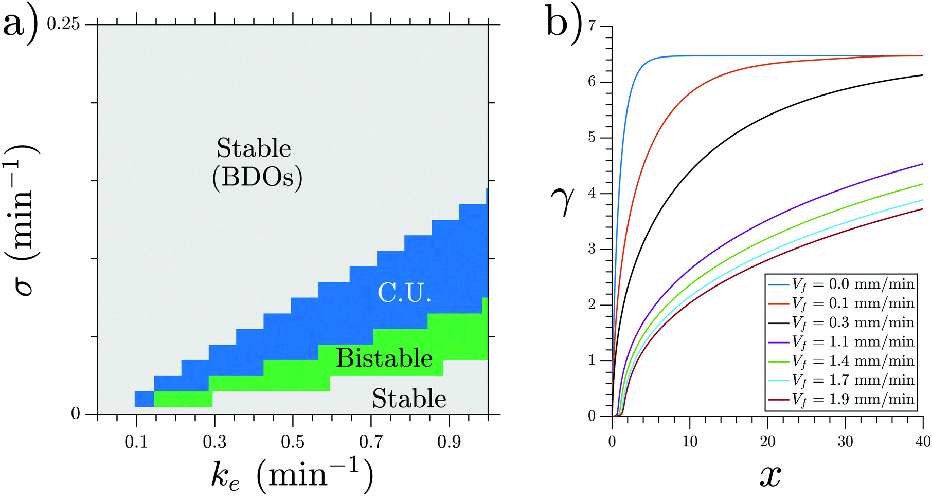 | ||
| Fig. 11 (a) Phase diagram of the MG model showing the range in which BDOs exist. Note that BDOs exist in both stable and connectively unstable (CU) regimes. (b) Steady state cAMP concentration γ obtained at σ = 0.3 min−1 and ke = 0.01 min−1. BDOs appear in the velocity range of 0.4 mm min−1 ≤ Vf ≤ 0.8 mm min−1. | ||
To mimic our experimental setup, we performed numerical simulations in a channel filled with PdsA− cells with the imposition of a Dirichlet boundary upstream. To account for the low degradation rate of the cells, we consider small values of degradation rate ke. Numerical simulations showed that at low-speed flows, the system reaches a time independent steady state. This solution is a monotonic curve that increases from a zero cAMP concentration at the channel upstream boundary up to a very high concentration at the channel downstream end (see Fig. 11b). At higher velocities of the advecting flow, an instability appears, and the system's solution is no longer time independent. The upstream boundary periodically emits waves that decay as they travel along the channel, similar to those observed in experiments. Examples of boundary-driven waves at three different flow speeds are shown in Fig. 12a–c and Movies S10–S12 (ESI†). We emphasize that this instability only appears when an absorbing boundary condition at the upstream boundary is enforced, thus emulating the advection of cAMP-free buffer.
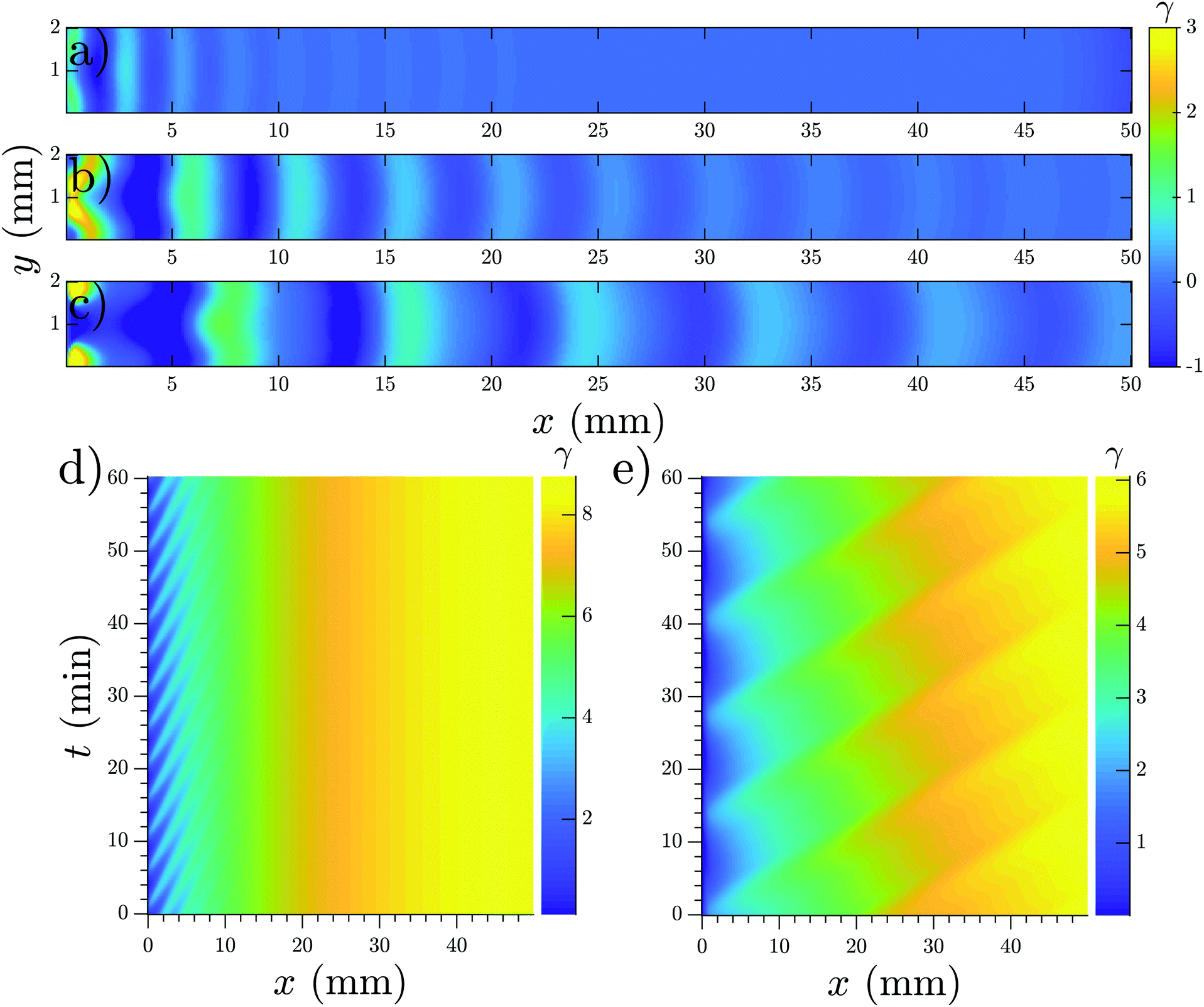 | ||
| Fig. 12 Boundary-driven waves developed in a channel with the Dirichlet boundary condition at x = 0. (a) Vf = 0.5 mm min−1, (b) Vf = 0.8 mm min−1 and (c) Vf = 1.1 mm min−1 (see Movies S10–S12, ESI†). Waves penetrate over longer distances at higher flow velocities. (d and e) Space–time plot of boundary-driven waves at imposed flow velocities of 0.5 mm min−1 and 2 mm min−1 showing higher periods at higher flow speeds. Other parameters are σ = 0.6 min−1 and ke = 0.01 min−1. Note that in (a–c), the mean value of γ is subtracted to enhance the contrast of the waves. As a result, γ finds negative values and its range is different from the space–time plots in parts (d and e). | ||
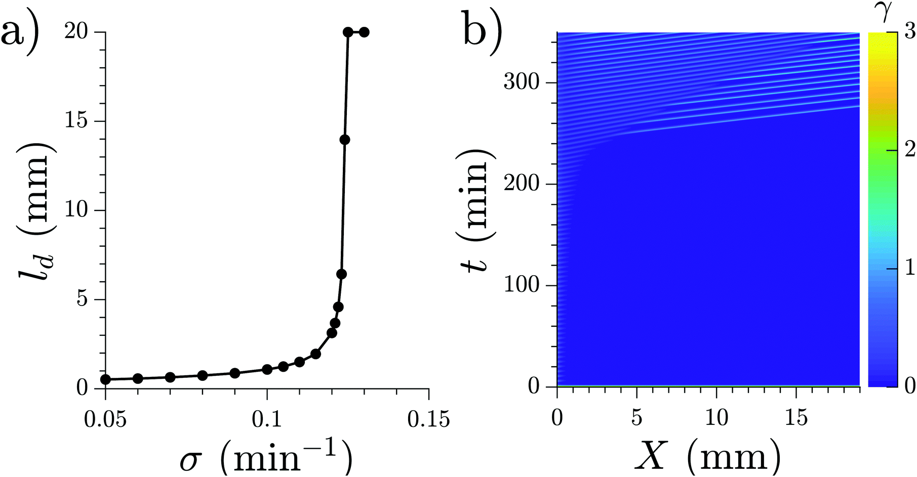
We studied the properties of these waves in a 1D geometry at a range of cAMP production rate intensities (σ) and velocities, while keeping the degradation of cAMP very low (ke = 0.01 min−1). The properties of these waves are summarized in Fig. 13; it can be seen that the period of the advected waves increases with the advecting flows, while the characteristic length ld increases with flow velocity. The existence of these waves is restricted to a range of velocities, which increases to include faster flows at higher production rates of cAMP. Once the advecting flows are too fast for this mechanism to exist, another numerical scheme needs to be used to periodically inject waves into the system. The high speed behavior is consistent with the previously reported behavior of WT,22 where the period is independent of the advecting flows with T ≈ 5–6 min.
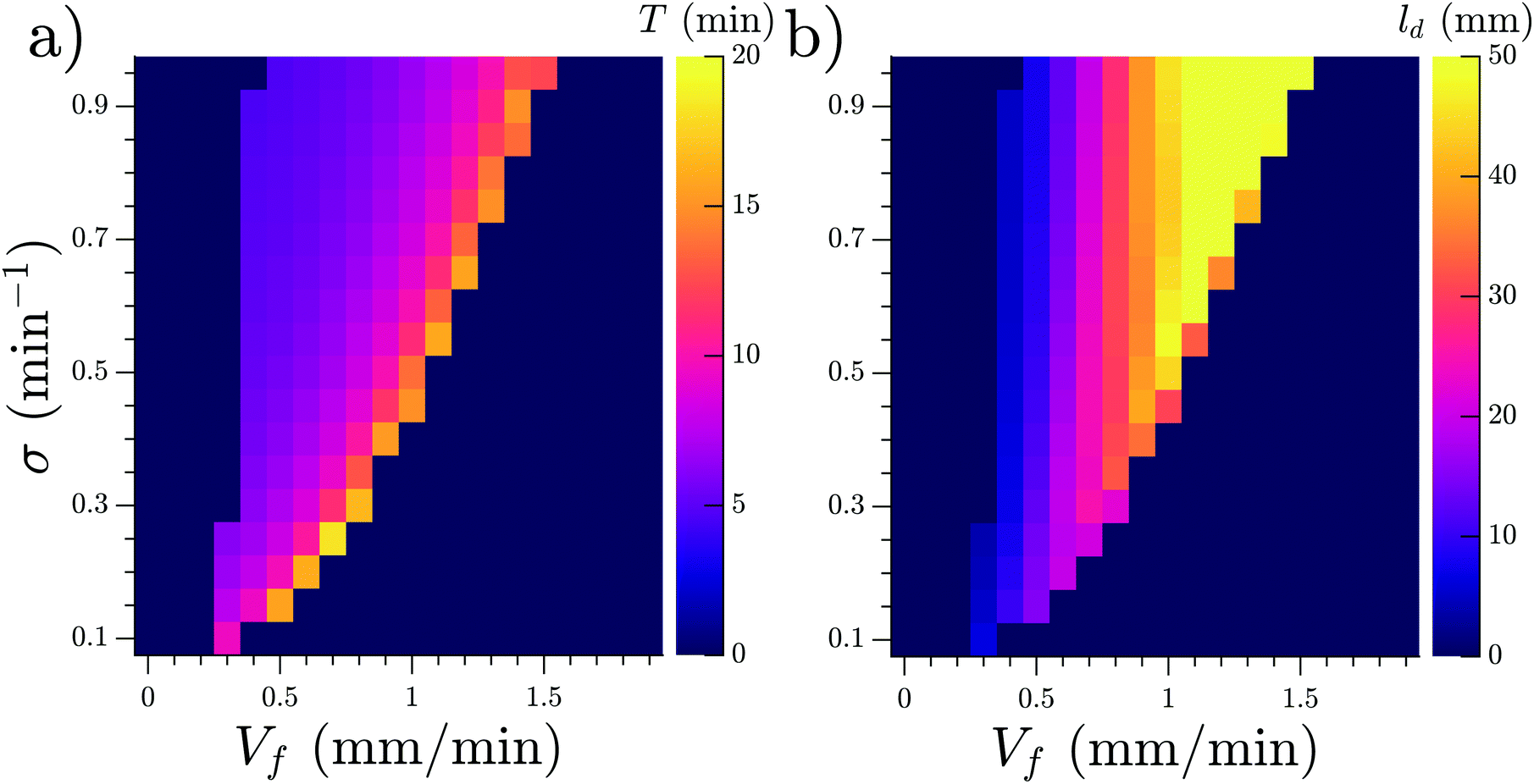 | ||
| Fig. 13 (a) Period T and (b) characteristic decay length ld of the observed waves as functions of the velocity of the advecting flow Vf and the production rate σ of cAMP. Note that simulations are performed in a 1D geometry. Degradation rate of cAMP is ke = 0.01 min−1 and channel length is L = 50 mm. | ||
We also performed numerical simulations emulating the experiments with WT cells in the inlet. In these simulations, the parameters were fixed as ke = 5.0 min−1 and σ = 0.55 min−1 for x < l with l = 1 mm to represent the inlet. With these parameters, the inlet oscillates with a fixed period and emits waves to the rest of the channel. In simulations including phosphodiesterase advection and WT cells in the inlet, we observed that the secreted phosphodiesterase was advected quickly downstream and therefore the phosphodiesterase concentration could be assumed to be constant along the channel during most of the experiment. Given this phosphodiesterase distribution, in the experiments where the cells are not prestarved and signaling starts after 3 hours, the system behaves like a channel filled with WT.
In the case where the WT cells are prestarved and start to fire immediately after being placed in the channel, we found that an increasing production rate of cAMP for the PdsA− cells reproduced the increasing decaying length in the system. Simulations for different production rates with fixed degradation rates (fixed at the WT value ke = 5.0 min) were performed, and their decay length increased with increasing production rate, as shown in Fig. 14a. An example of a simulation where the production rate increased over time as σ = Kt (K is a constant) can be seen in Fig. 14b; there, the decay length increases over time (see Movie S11, ESI†).
 | ||
| Fig. 14 (a) Characteristic length ld for the waves produced at the inlet by the WT cells. The degradation rate given by the effect of phosphodiesterase is fixed at ke = 5.0 min−1 for the whole channel. (b) Space–time representation of a numerical simulation with WT cells in the inlet (not shown) and linearly increasing cAMP production rate in the rest of the channel, σ = 0.001·t. Flow velocity is 0.7 mm min−1 (see Movie S13, ESI†). | ||
Finally, all of our simulations were performed in channels of width 2 mm to emulate the experimental setup. To examine the effect of channel width, we performed numerical simulations with channels of two different widths, 1 mm and 4 mm. As shown in the space–time plots in Fig. S1 and S2 (ESI†), the period of boundary-driven waves does not show a significant dependence, but the maximum cAMP concentration is lower for wider channels. Decay length of the waves seems to also depend on the channel width. Overall, the qualitative behavior of boundary-driven waves is similar at different channel widths. Furthermore, our simulations are performed in a 2D geometry and the effect of channel height is not considered. We note that for a wide and shallow microfluidic channel (large aspect ratio of width to height), the flow profile takes on a parabolic shape with respect to the height coordinate z. In the absence of diffusion, the concentration profile of cAMP in z direction would reflect the flow profile.1 However, in the presence of diffusion, as cAMP is advected downstream, it also spreads in the vertical direction. For a large diffusivity or shallow microfluidic channels, diffusion in the z direction prevents the formation of a parabolic concentration profile. Instead, it forms a plug concentration profile in the z direction meaning that cAMP concentration does not depend on z and quickly drops to zero at the boundaries. In his seminal work, Taylor has shown27 that the center of the plug moves with the mean flow velocity Vmean, while diffusive spreading of the plug about its center can be described by an effective diffusion coefficient given as
| Deff = D(1 +α Peh) | (2) |
where Peh is the Pećlet number defined as Peh = Vmeanh/D, h is the channel height and geometrical factor α for a shallow rectangular channel is equal to 1/210.28–30 Thus, in our simulations, the effect of height can be included by defining an effective diffusion coefficient. For example, for Vmean = 2 mm min−1, D = 0.024 mm2 min−1 and h = 0.1 mm, we obtain Deff = 0.025 mm2 min−1. Simulation with this value of Deff is shown in Fig. S3 (ESI†) and compared with the normal value of D. As expected, the results are virtually identical.
Discussion
Previous studies have shown that pulsing PdsA− cells with cAMP is not enough to rescue them.13,31 Due to the lack of degradation in a population of PdsA− cells, cAMP accumulates without producing waves, preventing the cells from aggregating naturally. It has been shown that adding external phosphodiesterase from a rat brain,31 PDE overexpressors,13 or by mixing with WT cells32 causes PdsA− cells to recover their aggregation capabilities.Here, we have shown that an influx of cAMP-free buffer not only recovers signaling in PdsA deficient cells, but also that these cells are capable of signaling and aggregation once the flow has been switched off. In our flow-through microfluidic setup filled with PdsA− cells, we observed cAMP waves after 3 hours of starvation with flow, independent of whether or not they were previously starved in a shaker. This confirms that reduced levels of cAMP are necessary for their development. Future experiments using fluorescent indicators14,33,34 for extracellular cAMP will be valuable to directly quantify the level of cAMP depletion needed to generate waves and thereby rescue PdsA− cells. These waves have a finite decay length inside the channel, which grows with the imposed flow velocity. In the presence of boundary-driven waves, cells advance in their developmental path, and thereby waves reach further downstream the channel after 6.5 hours throughtout the experiment. Since cells continue signaling after the flow is stopped, it is plausible that other types of phosphodiesterases such as PDE4 take over the role of PdsA during aggregation,12 having a higher activity in comparison to the normal presence of PdsA. Other biochemical experiments are necessary to confirm this hypothesis. Interestingly, the period of the spontaneous waves observed in the recovered population of PdsA− cells was much higher than that of the WT cells, and the rescued cells were located upstream of the channel, consistent with the area covered by decaying boundary-driven waves.
To examine the robustness of BDOs with respect to channel size, we performed a new set of experiments with a microfluidic channel of smaller height and width. The results for a channel of height 50 μm and width 1.5 mm are shown in Fig. S4 (ESI†). These experiments confirm that BDOs are relatively robust as we make the channel shallower and reduce the width, consistent with our numerical simulations (Fig. S1 and S2, ESI†).
Our numerical simulations show the nature of the instability that produces the waves in this system. A flow of cAMP-free buffer provides the destabilizing mechanism necessary for wave production, thus showing boundary-driven oscillations. At small flow speeds, the clean buffer produces depletion of cAMP at the upstream edge of the channel, thus allowing the cells located there to fire and produce a cAMP wave. As this wave travels downstream, the basal concentration of cAMP increases and the wave loses amplitude, decaying as it travels. At higher flow speeds, more clean buffer penetrates the system, thus the basal cAMP concentration increases more slowly along the channel (smaller gradients), therefore allowing the waves to travel further. In our simulations, there is a maximum velocity such that the boundary-driven oscillations exist. This is in disagreement with our experimental observations, where at higher flow speeds, wave generation continues to occur. We believe that the range of existence of this instability is marked by the change in the oscillating period observed in the experiments (see the vertical line in Fig. 2c). For Vf < 0.6 mm min−1, the wave period is large and changes with the advecting flow, while for Vf > 0.6 mm min−1, it is constant around T ≈ 5–6 min, and therefore these BDOs exist for Vf < 0.6 mm min−1. To test this hypothesis, we performed numerical simulations including a constant firing of the cells with T = 6 min. For the range of velocities where the boundary-driven oscillations exist, the period of these oscillations prevailed and the firing had no effect on the system. For higher velocities, the constant firing sets the period of the system.
Moreover, we used WT cells at the upstream end of the channel to rescue PdsA− cells. We observed waves with increasing penetration length that propagated inside the channel. This behavior was reproduced in our simulations with WT cells at the reservoir with an increasing cAMP production rate of PdsA− cells everywhere in the channel. Therefore, we attribute this increasing penetration length to the gradual development of the PdsA− cells in the channel. If the WT cells at the reservoir are not prestarved, then the WT cells develop along with the PdsA− cells and the flow-driven waves appear after 3 hours and are capable of penetrating throughout the channel.
Finally, it is shown that in a reaction-diffusion system, Dirichlet boundary conditions are able to destabilize the uniform steady state and generate stable, spatially non-uniform patterns,35 which can be applied to many patterning phenomena in biology, ecology or chemical systems. In this work, we show that by imposition of the Dirichlet boundary condition in experiment or numerical simulations, boundary-driven instabilities are relevant in the presence of advection. This could be a plausible mechanism in order to generate a continuous periodic influx of wave trains in an otherwise stable reaction-diffusion system.
Author contributions
A. G. designed the research. E. V. H. designed and carried out numerical simulations. T. E. performed the experiments. E. V. H., T. E. and A. G. analyzed the data. A. G., E. V. H. and T. E. wrote the manuscript.Conflicts of interest
There are no conflicts to declare.Acknowledgements
The authors thank M. S. Müller and K. Gunkel for their cheerful help with the preparation of the cells. T. E. acknowledges Deutsche Forschungsgemeinschaft (DFG), project number GH 184/1-1. E. V. H. thanks the Deutsche Akademische Austauschdienst (DAAD), Research Grants-Doctoral Programs in Germany. A. G. acknowledges MaxSynBio Consortium, which is jointly funded by the Federal Ministry of Education and Research of Germany and the Max Planck Society. Open Access funding was provided by the Max Planck Society.References
- E. Vidal-Henriquez, V. Zykov, E. Bodenschatz and A. Gholami, Chaos, 2017, 27, 103110 CrossRef PubMed.
- E. Pálsson and E. C. Cox, Proc. Natl. Acad. Sci. U. S. A., 1996, 93, 1151–1155 CrossRef PubMed.
- J. J. Tyson, K. A. Alexander, V. Manoranjan and J. Murray, Phys. D, 1989, 34, 193–207 CrossRef CAS.
- D. A. Kessler and H. Levine, Phys. Rev. E: Stat. Phys., Plasmas, Fluids, Relat. Interdiscip. Top., 1993, 48, 4801–4804 CrossRef PubMed.
- S. Almeida and R. Dilão, Phys. Rev. E, 2016, 93, 052402 CrossRef PubMed.
- J. T. Bonner, Cellular slime molds, Princeton University Press, Woodstock, 2015, vol. 2127 Search PubMed.
- W. Loomis, Dictyostelium discoideum: a developmental system, Elsevier, Amsterdam, 2012 Search PubMed.
- A. Theibert and P. N. Devreotes, J. Cell Biol., 1983, 97, 173–177 CrossRef CAS PubMed.
- C. Klein and M. H. Juliani, Cell, 1977, 10, 329–335 CrossRef CAS PubMed.
- D. Hereld, R. Vaughan, J. Y. Kim, J. Borleis and P. Devreotes, J. Biol. Chem., 1994, 269, 7036–7044 CAS.
- P. N. Devreotes and J. Sherring, J. Biol. Chem., 1985, 260, 6378–6384 CAS.
- S. Bader, A. Kortholt and P. J. Van Haastert, Biochem. J., 2007, 402, 153–161 CrossRef CAS PubMed.
- G. L. Garcia, E. C. Rericha, C. D. Heger, P. K. Goldsmith and C. A. Parent, Mol. Biol. Cell, 2009, 20, 3295–3304 CrossRef CAS PubMed.
- T. Gregor, K. Fujimoto, N. Masaki and S. Sawai, Science, 2010, 328, 1021–1025 CrossRef CAS PubMed.
- A. Gholami, O. Steinbock, V. Zykov and E. Bodenschatz, Phys. Rev. Lett., 2015, 114, 018103 CrossRef CAS PubMed.
- A. Gholami, O. Steinbock, V. Zykov and E. Bodenschatz, New J. Phys., 2015, 17, 063007 CrossRef.
- G. M. Whitesides, E. Ostuni, S. Takayama, X. Jiang and D. E. Ingber, Annu. Rev. Biomed. Eng., 2001, 3, 335–373 CrossRef CAS PubMed.
- A. D. Edelstein, M. A. Tsuchida, N. Amodaj, H. Pinkard, R. D. Vale and N. Stuurman, J. Microbiol. Methods, 2014, 1, e10 Search PubMed.
- D. A. Egolf, I. V. Melnikov and E. Bodenschatz, Phys. Rev. Lett., 1998, 80, 3228 CrossRef CAS.
- J.-L. Martiel and A. Goldbeter, Biophys. J., 1987, 52, 807 CrossRef CAS PubMed.
- J. Lauzeral, J. Halloy and A. Goldbeter, Proc. Natl. Acad. Sci. U. S. A., 1997, 94, 9153–9158 CrossRef CAS PubMed.
- T. Eckstein, E. Vidal-Henriquez, A. Bae, V. Zykov, E. Bodenschatz and A. Gholami, PLoS One, 2018, 13, 1–20 CrossRef CAS PubMed.
- E. Vidal-Henriquez and A. Gholami, Sci. Rep., 2019, 9, 3935 CrossRef PubMed.
- E. Pálsson, Biophys. J., 2009, 97, 2388–2398 CrossRef PubMed.
- R. Merson and Proc. Symp, Data Process., 1957, 1–25 Search PubMed.
- B. Koren, in Numerical methods for advection-diffusion problems, ed. C. B. Vreugdenhil, Vieweg, Braunschweig, 1993, pp. 117–138 Search PubMed.
- G. I. Taylor, Proc. R. Soc. London, Ser. A, 1953, 219, 186–203 CAS.
- D. A. Beard, J. Appl. Phys., 2001, 89, 4667–4669 CrossRef CAS.
- K. D. Dorfman and H. Brenner, J. Appl. Phys., 2001, 90, 6553–6554 CrossRef CAS.
- A. J. Bae, C. Beta and E. Bodenschatz, Lab Chip, 2009, 9, 3059–3065 RSC.
- M. Darmon, J. Barra and P. Brachet, J. Cell Sci., 1978, 31, 233–243 CAS.
- R. Sucgang, C. J. Weijer, F. Siegert, J. Franke and R. H. Kessin, Dev. Biol., 1997, 192, 181–192 CrossRef CAS PubMed.
- P. N. Devreotes, M. J. Potel and S. A. MacKay, Dev. Biol., 1983, 96, 405–415 CrossRef CAS PubMed.
- Y. Ohta, T. Furuta, T. Nagai and K. Horikawa, Sci. Rep., 2018, 8, 1–9 CrossRef CAS PubMed.
- P. Maini and M. Myerscough, Appl. Math. Lett., 1997, 10, 1–4 CrossRef.
Footnotes |
| † Electronic supplementary information (ESI) available. See DOI: 10.1039/c9sm02291k |
| ‡ These authors contributed equally to this work. |
| This journal is © The Royal Society of Chemistry 2020 |