DOI:
10.1039/C9SM02103E
(Paper)
Soft Matter, 2020,
16, 3991-3999
Gait-optimized locomotion of wave-driven soft sheets†
Received
23rd October 2019
, Accepted 27th March 2020
First published on 30th March 2020
Abstract
Inspired by the robust locomotion of limbless animals in a range of environments, the development of soft robots capable of moving by localized swelling, bending, and other forms of differential growth has become a target for soft matter research over the last decade. Engineered soft robots exhibit a wide range of morphologies, but theoretical investigations of soft robot locomotion have largely been limited to slender bodied or one-dimensional examples. Here, we demonstrate design principles regarding the locomotion of two-dimensional soft materials driven by morphoelastic waves along a dry substrate. Focusing on the essential common aspects of many natural and man-made soft actuators, a continuum model is developed which links the deformation of a thin elastic sheet to surface-bound excitation waves. Through a combination of analytic and numerical methods, we investigate the relationship between induced active stress and self-propulsion performance of self-propelling sheets driven by FitzHugh–Nagumo type chemical waves. Examining the role of both sheet geometry and terrain geography on locomotion, our results can provide guidance for the design of more efficient soft crawling devices.
1 Introduction
Nearly all motile organisms achieve locomotion through some manner of active deformation, and soft matter researchers are increasingly able to replicate biomechanical strategies in the design of soft robotics.1–3 Arguably the simplest strategy for terrestrial motion is crawling: via a temporally patterned series of contractions and expansions, a deformable solid drags itself along a surface.4 Crawling has the advantage over traditional mechanical systems of being highly adaptable against changing terrain, and it requires far fewer specialized parts than a multi-pedal system.5–9 Until recently, most research on the topic has focused on slender designs inspired by the peristaltic motions found in snails, worms, and certain snakes.10,11 Locomotion of active solids in one dimension has been studied extensively in the context of swelling gels, shape memory polymers, or dielectric and ferromagnetic materials.12–17 But nature is full of motile organisms which possess spatially-extended, sheet-like bodies (Fig. 1A and B), and engineers are actively exploring the high-dimensional design space of robot morphologies (Fig. 1C–F).18–23 These efforts require new theory to be developed to address and understand the increasingly complex patterns of deformation and growth employed in 2D and 3D soft systems.
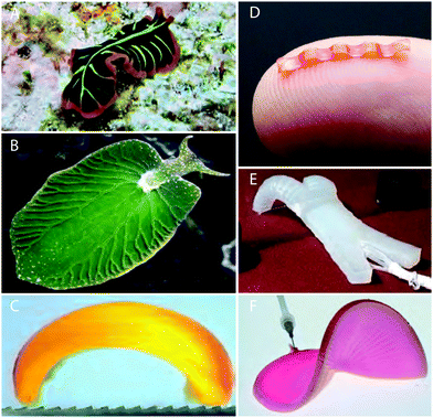 |
| | Fig. 1 Soft active sheets in natural and engineered contexts. (A) Flatworms are capable of undulating over on land and sea.24 (B) A “solar-powered slug” has a leaf-like body to optimize photosynthesis.25,26 (C) A walking hydrogel driven by a Belousov–Zhabotinsky (BZ) reaction walks along an anisotropic substrate.14 (D) Millimeter-scale soft robot shows sustained peristaltic locomotion.27 (E) Inflation-driven soft robot capable of multiple gaits.7 (F) Pneumatic shape-morphing elastomer structure6 exhibits tuneable configurations. | |
In this paper, we use methods from the theory of morphoelasticity to examine the locomotion of an actively deformable elastic shell crawling upon a dry frictional surface. In Section 2, a toy model is constructed in which deformation is coupled to a surface-bound excitable wave, mimicking, for instance, the swelling seen in BZ-driven hydrogel actuators.28 Analysis of this model reveals crucial qualitative differences between 1D and 2D crawling bodies: geometric incompatibility makes the relationship between active stress and deformation far less trivial in two dimensions. In Section 3, this relationship is derived exactly in the small strain limit, allowing us to demonstrate substantial deviations in the peristalsis-induced velocity of a crawling body in 1D versus 2D.4,29 Following this, we use numerical approaches to examine larger deformation regimes for a sheet driven by FitzHugh–Nagumo type traveling waves. Our main focus will be on how sheet velocity can be maximized by the choice of active coupling parameters and by sheet geometry for a particular wave pattern. We conclude our study by exploring the robustness of crawling locomotion over non-uniform terrain.
2 Model
We consider hyperelastic, neo-Hookean elastic sheets subject to isotropic, non-homogeneous contraction, expansion, and curvature: this approach is a good match to the known behavior of already existing sheet-like devices.30 Equations of motion are obtained variationally from energy functionals based on the standard Koiter shell model.31–33 Elastic dynamics are over-damped, consistent with growth processes in both living and engineered systems.28 As a consequence, it is assumed at any time t that the system is in its minimal energy configuration. For our system, these energy functionals are given in terms of the difference between the instantaneous metric a and curvature b tensors of the surface, and prescribed reference tensors ā and ![[b with combining macron]](https://www.rsc.org/images/entities/b_char_0062_0304.gif) which define the local equilibrium behavior:32,34
which define the local equilibrium behavior:32,34| |  | (1a) |
| |  | (1b) |
These equations have been non-dimensionalized by choosing units such that the sheet length L and Young modulus Y are equal to one, along with the characteristic velocity associated with eqn (3) below. Throughout, we consider a constant Poisson ratio ν = 0.5, and the ratio of sheet thickness of length h is set to 0.03. The integration domain ![[small omega, Greek, macron]](https://www.rsc.org/images/entities/i_char_e0da.gif) is the undeformed reference surface of the sheet, and d
is the undeformed reference surface of the sheet, and d![[small omega, Greek, macron]](https://www.rsc.org/images/entities/i_char_e0da.gif) is the corresponding surface area element. Note that the configuration with minimal energy generally has nonzero energy: for arbitrary growth, the reference tensors are not necessarily compatible and thus the zero-energy state cannot be embedded in 3D Euclidean space.35 The elastic sheet is placed in a gravitation field, Fg = −ρgẑ. In our simulations, we chose the gravitational force per unit area ρg = 2.5 × 10⁻⁴, ensuring that gravitational effects on deformation are negligible. Further, the sheet rests upon a rigid surface, represented by the repulsive force
is the corresponding surface area element. Note that the configuration with minimal energy generally has nonzero energy: for arbitrary growth, the reference tensors are not necessarily compatible and thus the zero-energy state cannot be embedded in 3D Euclidean space.35 The elastic sheet is placed in a gravitation field, Fg = −ρgẑ. In our simulations, we chose the gravitational force per unit area ρg = 2.5 × 10⁻⁴, ensuring that gravitational effects on deformation are negligible. Further, the sheet rests upon a rigid surface, represented by the repulsive force| |  | (2) |
where k = 0.5, β = 2.5 × 10⁻⁷, and z and vz are the distance and velocity of the sheet normal to the ground. This contact force model was chosen because it produces an effectively rigid ground (with only negligible penetration by the sheet during deformation) with minimal numerical instability. Restricting ourselves to a rigid ground is essential, as feedback between deformable sheets and a soft floor can trigger complex patterns which would greatly increase the difficulty of analysis.36 We focus on floors with dry interfaces, described by the traditional Coulomb friction Ff = −μ|Fn|![[v with combining circumflex]](https://www.rsc.org/images/entities/i_char_0076_0302.gif) t, where
t, where ![[v with combining circumflex]](https://www.rsc.org/images/entities/i_char_0076_0302.gif) t is the local sheet velocity unit vector tangent to the ground. To ensure numerical stability, our simulations replace this law with the approximation
t is the local sheet velocity unit vector tangent to the ground. To ensure numerical stability, our simulations replace this law with the approximation| |  | (3) |
with μ = 0.7 and velocity normalization is chosen so that v0 = 1. Together with L = 1, units of time in this normalization are thus t0 = L/v0. While some biological crawlers feature more complex surface interactions because of lubricating mucous layers or cilia,10 this choice of friction is consistent with prior theoretical work on locomotion,37 and avoids many of the common numerical difficulties associated with discontinuities in sliding friction. Active deformation is induced according to a time-varying scalar field c(x,y,t) defined over the reference sheet, which can be taken as a proxy for a surface-bound chemical or otherwise excitable process (see Fig. 2D). This field exerts active mechanical stress on the sheet by direct modification of the reference tensors described above, consistent with prior work on the active deformation of thin shells:33,34,38| | ā → exp(2αc)ā, ![[b with combining macron]](https://www.rsc.org/images/entities/b_char_0062_0304.gif) → −βcā, → −βcā, | (4) |
The exponential form used above prevents the reference metric from becoming negative in the high contraction limit, which would raise concerns of unphysical stresses. In all simulations described below, we numerically integrate the equations of motions acquired by summing the combined effects of internal forces derived from the potential energy in eqn (1) and the external forces described above. Further details on these equations of motion and the numerical methodology can be found in the Appendix. Overall, this model represents a general formulation for isotropic deformations of a soft sheet, and, when coupled to regular wave pulses, exhibits sustained locomotion (Fig. 2).
 |
| | Fig. 2 Active waves trigger peristalsis-like gaits in sheets. (A) Top: Snapshot of 2D simulation, with surface colored to show local concentration and arrows indicating friction force vector Ff. The wireframe beneath indicates the undeformed simulation mesh of the sheet. Bottom: An undeformed surface, with arrows representing gravity Fg, the normal force Fn and friction Ff. The coupling parameter α controls the local stretching of the surface in response to the concentration field (red), while the parameter β governs local bending, see eqn (4). (B and C) Kymographs showing chemical and mechanical time evolution of a walking sheet at α = −0.25 and β = −0.15. Values are averaged along the direction traverse to the waves propagation. Panel B depicts the concentration profile c, and panel C shows the longitudinal displacement. (D) Snapshots of one gait over the course of a single period, corresponding to the plots in B and C. The surface wave triggers expansion and bending of the surface, inducing backward motion of the sheet. | |
3 Results
3.1 Flat crawling sheets
Crawling is perhaps the most extensively studied gait for soft robots because it is ubiquitous in nature and easy to reproduce mechanically.4,39 So we first consider the simple motion of a crawling elastic sheet with no out-of-plane deformation. We employ an approximate analytical approach for the overdamped 1D regime in which elastic forces dominate over friction, and the temporal period of the wave is much longer than the elastic equilibration timescale. Such an approximation is suitable for cases in which mechanical equilibration occurs must faster than growth processes, and is a common assumption in morphoelastic processes.32 Because elasticity dominates over damping, we assume that at each instant, the system is in its reference configuration and is quasi-statically evolving from one moment to the next. Although friction accounts for the net motion of the body, elasticity is so dominant that it can be assumed that friction affects the center-of-mass position only and not the shape. In the regime where coupling α ≪ 1, β = 0, it is possible to linearize the deformation dependence in eqn (4) and solve the system to the lowest order to find how net velocity averaged over time scales with α.
Before addressing the more complex 2D case, it is instructive to consider a 1D body, for which growth induced geometric incompatibility does not occur.40 Because the instantaneous configuration in 1D is identical to the reference configuration induced by the wave, the deformation at a point S ∈ [0, 1] in the undeformed reference coordinates can be written as:
| |  | (5) |
Assuming that the effect of friction on the body shape is negligible, the instantaneous velocity at each point can be calculated for a given wave in the center of mass frame as
| |  | (6) |
In the lab frame, the total friction force acting on the sheet must be zero, which means that
| |  | (7) |
Here,
f(
S,
t) is the local friction acting on the sheet at material point
S and time
t. This value is a constant with the opposite sign as the local sheet velocity in the lab frame, which is given as
vcm(
S,
t) +
Vnet(
t); that is, the sum of the local velocity in the center of mass frame and the net velocity of the center of mass in the lab frame. The prefactor 1 + ∂
Su(
S,
t) accounts for the modification of surface friction due to the change in surface element size.
39 This relation defines
Vnet(
t) as dependent on the deformation
via a nonlinear, implicit integral equation, and deriving a closed form solution is challenging. One elementary case for which a solution can be found is the simple traveling sine wave
c(
S,
t) = sin(2π
nS − 2π
t/
T), for an arbitrary non-zero integer
n. In this case,
and translational symmetry allows us to ignore the time dependence in
eqn (7), and the integral can be solved for the fixed value
Vnetvia piecewise integration to find
| |  | (8) |
This equation can be solved perturbatively for small
α to give
| |  | (9) |
This result presents an interesting counterpoint to existing results for peristaltic crawling with viscous friction. In the viscous friction case, there is also a quadratic dependence on deformation strength, but the net velocity is in the same direction as, rather than opposed to, the direction of wave propagation.
39
In the 2D regime, non-homogenous growth produced by a generic wave pulse makes the sheet configuration a non-trivial function of the concentration field c, and finding the exact deformation field for which eqn (1) vanishes is only practical for special cases. In fact, the deformed reference configuration is not always directly embeddable in real space in two or more dimensions, and often no stress free configuration exists: the deformation merely minimizes our energy functional, rather than making it vanish.35 However, working in the limit where β = 0 and |α| ≪ 1, it is safe to assume deformations induced by active stress are small, so our Koiter energy equations are replaced with a linearized set of elastostatic equations
| | | εij = [(1 + ν)σij − νδijσkk] + (1 + ν)αcδij | (10b) |
Here
σij and
εij are the conventionally defined linear stress and strain tensors, and
δij denotes the Kronecker delta symbol. The first equation is the usual expression for the balance of forces at equilibrium. The second equation modifies the normal constitutive relation for an elastic body by the addition of the rightmost term, which represents the isotropic active stress induced by the local concentration field. As constructed, these equations are identical in form to the standard formulations of linear thermo-elasticity,
41 and we can borrow the results developed for that field. In the Appendix, we describe in detail the solution of these equations for a rectangular elastic sheet with free boundary conditions by way of the stress function formulation. With the exact deformation field
u(
x,
t) derived, where
x = (
x,
y) parameterizes the undeformed reference surface, the velocity of each point in the center of mass frame can be calculated as before. As shown in
Fig. 3A, the analytical solution obtained this way closely matches numerical simulations. In this paper we consider waves which propagate along the
y-axis, with no
x-dependence, and so in the lab frame, the only net velocity is along the
y-axis. Thus, balance of forces requires
| |  | (11) |
where
J(
x,
t) = 1 +
εxx(
x,
t) +
εyy(
x,
t) is the deformed element area in 2D. Unlike the 1D case, this equation cannot be easily evaluated for the exact deformation field, even if
c(
y,
t) is as simple as a sinusoidal wave. Numerical root-finding methods, however, can be used to calculate
Vnet to arbitrary precision, revealing that, to the lowest order, crawling speed is also quadratic in
α (
Fig. 3B). However, the net displacement greatly underperforms in comparison to the 1D case. This result follows directly from the nonlinearity of dry friction—with the total magnitude of friction at a given point constant, contraction and expansion traverse to the wave reduces the net force in the longitudinal direction (Movie 1, ESI
†).
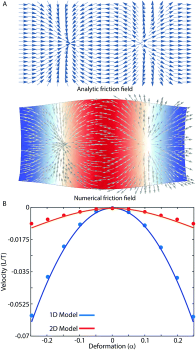 |
| | Fig. 3 Sheet locomotion is exactly solvable for small deformation. (A) Snapshots of the instantaneous surface friction on an elastic sheet driven by a sinusoidal wave. Top panel: Friction field calculated analytically as described in the text. Bottom: Deformed sheet according to FEM simulations for α = 0.25, with color depicting local value of c and arrows determined by eqn (3). For full range of motion, see Movie 1 (ESI†). (B) Comparison of 1D and 2D locomotion. In both cases, velocity exhibits a quadratic dependence on α to the lowest order. Symbols represent results of simulated crawling, while lines are predicted results from theory. In both cases, predictions closely match numerical results, but begin to diverge slightly as α grows. The rectangular reference geometry of the sheet has length L = 1 and width L/2, with sheet thickness set to h = 0.03. | |
3.2 Optimal gaits for finite deformations
Thus far our analysis has been constrained to entirely in-plane motion, but sufficiently strong deformation will produce out-of-plane buckling of the sheet as it moves, as will waves that induce a preferred curvature on the initially flat sheet. In such cases, the complex shape changes generally make analytical approaches unfeasible.42 Instead, we investigate the relationship between surface activity and locomotion numerically, using the subdivision FEM approach described in Vetter et al. 2013.43 In the interest of representing a plausible active wave, our numerical model c(y,t) evolves according to a FitzHugh–Nagumo type equation, which is an archetypal system for representing traveling reaction diffusion waves| | | ct = γ2∇2c + c(1 − c)(c − ν) − w | (12a) |
This model provides a generic representation of the types of wave-driven activity required for autonomous soft robots, so that the main results below can be expected to generalize qualitatively to other wave propagation models.
We choose parameter values that produce traveling wave solutions44 in the oscillatory regime: ν = −0.01, κ = 0.0001, ε = 0.05, and γ = 0.02. Initial conditions are of the form c(t = 0) = y2/(1 + y2), w(t = 0) = 0, which produces well defined waves that propagate perpendicular to the x-axis. Boundary conditions for the wave along the edge of the sheet are of the Neumann type.
A rectangular crawling sheet's motion was explored over a range of parameters values for the coupling parameter α and β. The range plotted corresponds to local swelling/contraction on the order of 50–150% in undeformed size, and preferred radii of curvatures up to the order of 0.05L. Our numerical scans of the (α,β) space revealed a roughly saddle point shaped velocity surface (Fig. 4A). Depending on the active surface mechanics produced by the wave, the sheet can move in the same (Fig. 4B and Movie 2 top, ESI†) or opposite (Fig. 4C and Movie 2 bottom, ESI†) direction as the wave propagation. Two notable curves can be highlighted in the (α,β) space, associated with an active bilayer composed of one actively swelling layer and one passive layer (one curve for the active layer being on top, and one for the bottom), as shown by the black lines on Fig. 4A.34 Near the origin, these curves are approximately β = ±100α.
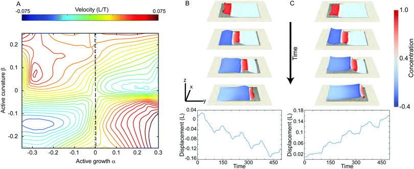 |
| | Fig. 4 Velocity parameter space for a rectangular sheet as in Fig. 3 exhibits a saddle point dependence on deformation. (A) Parameter space diagram showing mean velocity as a function of the coupling parameters α and β. The dashed (dotted) line represent the special case of coupling parameters equivalent to the deformation of a thin bilayer with an active top (bottom) layer attached to a passive elastic bottom (top) layer, derived by equating our model with the formulation suggested by Pezzulla et al.;34 along these lines active growth is nonzero but negligible compared with bending. (B) Snapshots of an optimal backward moving sheet, taken at α = −0.25 and β = −0.15. Bottom panels show the center of mass position as a function of time over the first 4 periods. (C) As in panel B, but for an optimal forward gait at α = −0.3 and β = 0.1. In all cases, h/L = 0.03, and the aspect ratio is 2 to 1. See Movie 2 (ESI†) for full dynamics corresponding to panels B and C. | |
3.3 Sheet geometry
Moving on, the next question is how sheet shape influences locomotion. We examine how the speed of the two cases shown in Fig. 4B and C depends on different sheet shapes. In particular, a parameter space was explored in which back and front sides of the sheet w1 and w2 were varied, while simultaneously changing the length  to keep total area constant (Fig. 5, inset). The two cases exhibit markedly different geometry dependence. For the case shown in Fig. 5A, the sheet exhibits a local maximum velocity for L′ ≈ 0.9L, where L is the length of the sheet in Fig. 2–4. For the case corresponding to Fig. 4C, we see consistent retrograde velocity, but with a maximum speed around L′ ≈ 1.4L. What is interesting is that in both cases, the maximum speed has a monotonic dependence on w1/w2: in particular, it appears preferable to widen the leading edge and narrow the rear edge of the sheet with respect to the direction of net velocity.
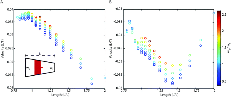 |
| | Fig. 5 Forward (A) and backward (B) velocity is optimized by tuning the ratio of leading (w2) and rear (w1) edge widths for trapezoidal sheets. (A) Inset diagram showing how the shape is varied: front and back widths (defined relative to the chemical wave propagation) are varied, with L chosen for each value to preserve total area A = 0.5 between simulations. For forward-motion parameters corresponding to Fig. 4C, velocity is optimized by increasing w2/w1. See Movie 3 (ESI†) for further comparison. (B) For backward-motion parameters as in Fig. 4B, the direction of motion remains the same over a range of sheet shapes, but speed is maximized at a value of L′ ≈ 1.4L, where L is the length of the rectangular sheet in Fig. 2–4. | |
3.4 External geometry
A central difference between soft and rigid robots lies in the former's ability to conform to different terrains, and it is hoped that this ability will make soft robots better at traversing obstacles.45 We consider the behavior of a rectangular sheet on a periodic surface with height| |  | (13) |
where λx and λy are the wavelengths in the directions perpendicular and parallel to the sheet's motion, and the amplitude A = 0.02, and the origin chosen to be the sheet's initial centroid position. The motion of the sheet was simulated over a range of surface wavelengths, as shown in Fig. 6A and Movie 4 (ESI†), revealing a highly nonlinear velocity landscape.
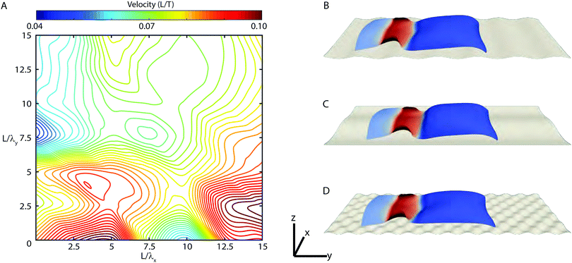 |
| | Fig. 6 Self-propulsion of rectangular sheets exhibits complex dependence on ground topography. A sheet with the same coupling parameters as that in Fig. 3B is placed upon a periodic curved surface defined as z = A![[thin space (1/6-em)]](https://www.rsc.org/images/entities/char_2009.gif) sin(2πx/λx)sin(2πy/λy). (A) While the sheet is capable of navigating the surface for all wavelengths, the dependence of velocity on either wavelength is highly nonlinear. (B) For L/λy = 7.5 and L/λx = 0, ridges perpendicular to the direction of motion restrict deformation and reduce locomotion speed. (C) Periodic variation of the substrate along the x-axis exhibits the greatest influence on net speed. For λx = L/5, motion is enhanced. (D) For sufficiently fine surface variation, such as this example for λx = λy = L/15, velocity approaches that of a flat plane. See Movie 4 (ESI†) for full dynamics corresponding to panels B, C, and D. sin(2πx/λx)sin(2πy/λy). (A) While the sheet is capable of navigating the surface for all wavelengths, the dependence of velocity on either wavelength is highly nonlinear. (B) For L/λy = 7.5 and L/λx = 0, ridges perpendicular to the direction of motion restrict deformation and reduce locomotion speed. (C) Periodic variation of the substrate along the x-axis exhibits the greatest influence on net speed. For λx = L/5, motion is enhanced. (D) For sufficiently fine surface variation, such as this example for λx = λy = L/15, velocity approaches that of a flat plane. See Movie 4 (ESI†) for full dynamics corresponding to panels B, C, and D. | |
Consider the extreme cases represented in our parameter space. Point B represents the minimal observed velocity of any tested terrain, and coincides with the landscape shown in Fig. 6B. In this scenario, we observe the sheet deform down into the ridged terrain, which reduces its forward extension and slows net speed. Point C, by contrast, is our local maximum. Here, traverse deformation of the substrate increases the normal force near the center line and decreases it near the edges, increasing net speed consistent with Fig. 5. Finally, it should be noted that as both traverse and longitudinal wavelengths become sufficiently small (point D), the net speed once again approaches its velocity on a flat surface. While some surfaces clearly enhance motion, and some negatively impact it, it is important to note that the sheet maintains coherent forward velocity in all tested cases, demonstrating that sheets allow for robust motion on complex terrain.
4 Conclusions
Using methods from morphoelasticity, we examined how a number of factors influence the crawling velocity of an actively deforming soft sheet. In particular, it was demonstrated how the relationship between velocity and active coupling parameters can be derived in the small strain limit, and an explicit solution in the case of sinusoidal driving waves was provided. For large strains, we showed that both the magnitude and direction of motion can be tuned as a function of deformation coupling. Interestingly, the above model predicts that an experimentally realizable bilayer system composed of passive and active monolayers will consistently move in the same direction as the driving wave, regardless of whether the active layer expands or contracts, or whether it is the top or bottom layer that is active. Furthermore, we found that the velocity is consistently enhanced by tail-heavy sheet geometries, and that active sheets can effectively maneuver across a range of different corrugated terrains. These results can help guide to future development of sheet-like soft automata.
The present study focussed on a single facet of the locomotion of spatially extended soft robots, and a rich set of unanswered questions remain. The importance of shape and finite size effects needs to be investigated further, and exploring sheets with holes46 could open new design routes towards more efficient locomotion. While our results address the case of crawling on a dry substrate, recent theoretical work has highlighted the radically different behavior of active sheets immersed in a fluid medium.47 Little is understood about the optimization of motion through complex fluids or granular media, or even over fluid–air interfaces along which some real-world snails crawl.48 Furthermore, active sheets driven by turbulent patterns, rather than the regular driving waves studied here, have been examined experimentally for creating tunable actuating films49 and merits detailed theoretical consideration. Finally, recent works have highlighted the importance of mechanical feedback for tuning self-deformations50,51 – exploring how these and other feedback mechanisms could be used to achieve adaptable locomotion offers yet another interesting direction for future research.
Conflicts of interest
There are no conflicts to declare.
Appendix A
A.1 Linear active deformations in two dimensions
We describe the method for calculating the active-stress induced deformation of a rectangular elastic sheet of length L and width L/2 centered at the origin. Our discussion is confined to the case where c(y,t) is constant along the x-axis, but the methods described here can be adapted without difficulty to more general cases. An extensive body of literature exists for solving linear elasticity problems involving non-uniform isotropic expansion/contraction in the context of thermoelasticity.41 In particular, we employ a solution method originally developed for the linear deformation of a rectangular sheet due to a non-uniform thermal distribution.52 In terms of the Airy stress function χ, where σxx = ∂yyχ, σxy = −2∂xyχ, and σyy = ∂xxχ, eqn (10) can be expressed asIn a thermostatic problem, in which c(x,t) is replaced with an equilibrium temperature field, the right hand side vanishes except at sources and sinks. The active wave profiles discussed in this paper, however, have no such property. Assuming free boundary condition (∂yyχ = 0 at x = ±L/4 and ∂xxχ = 0 at y = ±L/2) and that the wave is dependent only on the y coordinate, the general solution for a given equilibrium shape of the sheet is| | 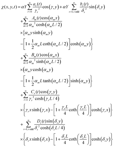 | (15) |
with δs = sπ/L, αm = 4πm/L, and γr = 2rπ/L. The coefficients ar(t) and bs(t) are the Fourier coefficients of the wave c(y,t), given by
For a traveling sine wave, this reduces to ar = δ1r![[thin space (1/6-em)]](https://www.rsc.org/images/entities/char_2009.gif) cos(ωt) and bs(t) = δ1s
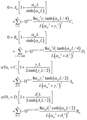
cos(ωt) and bs(t) = δ1s![[thin space (1/6-em)]](https://www.rsc.org/images/entities/char_2009.gif) sin(ωt), which greatly simplifies the subsequent calculation. The requirement of free boundaries leads to the following system of equations for the time-dependent amplitudes Am(t), Bm(t), Cr(t) and Ds(t)
sin(ωt), which greatly simplifies the subsequent calculation. The requirement of free boundaries leads to the following system of equations for the time-dependent amplitudes Am(t), Bm(t), Cr(t) and Ds(t)
Practically speaking, the solutions of these linear amplitude equations for only a finite number of nodes rapidly converge, and modes much smaller than that of the dominant mode of c produce only negligible changes to the resulting deformation field. For a traveling sine wave, we find that using the first 20 modes produced reliable solutions. The full series form of ϕ(x,y,t), and the stresses and strains derived from it, are too lengthy to reproduce directly, but a plot of values of the amplitudes is included for reference (Fig. 7).
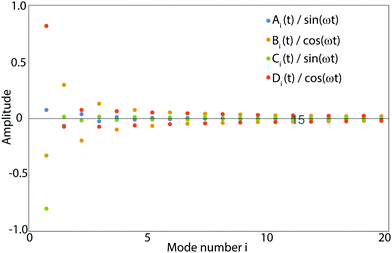 |
| | Fig. 7 Amplitudes of the first twenty modes for the solution of the 2D rectangular sheet as deformed by a traveling sine wave of wavelength equal to sheet length L. The rapid decay of amplitude allows us to truncate the infinite sum in eqn (15). | |
A.2 Numerical methods
Numerical FEM simulations are carried out using the following method. Let ααβ = ½(aαβ − āαβ) and βαβ = ![[b with combining macron]](https://www.rsc.org/images/entities/i_char_0062_0304.gif) αβ − bαβ. The Koiter potential energy per unit area can be rewritten as
αβ − bαβ. The Koiter potential energy per unit area can be rewritten as
where K = h/(1 − ν2) and D = h3/12(1 − ν2).43Hαβγδ is the isotropic plane-stress elasticity tensor in curvilinear coordinates
From this energy density, we can derive the curvilinear membrane stress
and the bending stress
Following the usual subdivision finite elements approach, the surface is divided using the libMesh finite element framework into Ne elements, and on each element e the trial space is spanned by a set of shape functions NIξ, η for I = 1,…,Nfe. Under this discretization, the deformation field and its derivatives may be written as a linear combination of the test functions
The generalized forces acting on each node are written in this formulation as
The bracketed terms {·}e,qp represent evaluation at the quadrature point qp on element e; wp is the weight at point p associated with our quadrature rule; and ![[j with combining macron]](https://www.rsc.org/images/entities/i_char_006a_0304.gif) is the Jacobian determinant of the reference surface. The equations of motion are
is the Jacobian determinant of the reference surface. The equations of motion are| |  | (16) |
with the mass matrix  . Integration of the equations of motion in time is performed via a Newmark-beta method with integration parameters β = 1/4 and γ = 1/2. Further details on this approach can be found in Vetter et al. 2013.43 Simulations were performed on a triangular mesh with 3720 elements, and integration was carried out with timestep dt = 5 × 10⁻³. The integration of eqn (12) is carried out simultaneously according to Euler's method.
Acknowledgements
We thank Alexander Mietke, Jan Totz, Catherine Padhi, and Norbert Stoop for helpful comments. This work was supported by the MIT Solomon Buchsbaum Research Fund.
References
- M. Wehner, R. L. Truby, D. J. Fitzgerald, B. Mosadegh, G. M. Whitesides, J. A. Lewis and R. J. Wood, Nature, 2016, 536, 451–455 CrossRef CAS PubMed.
- S. Li, D. M. Vogt, D. Rus and R. J. Wood, Proc. Natl. Acad. Sci. U. S. A., 2017, 114, 13132–13137 CrossRef CAS PubMed.
- J. C. Chrispell, L. J. Fauci and M. Shelley, Phys. Fluids, 2013, 25, e1002167 Search PubMed.
- M. Calisti, G. Picardi and C. Laschi, J. R. Soc., Interface, 2017, 14, 20170101 CrossRef PubMed.
- P. Gidoni, G. Noselli and A. DeSimone, Int. J. Non-Linear Mech., 2014, 61, 65–73 CrossRef.
- E. Siéfert, E. Reyssat, J. Bico and B. Roman, Nat. Mater., 2019, 18, 24–28 CrossRef PubMed.
- R. F. Shepherd, F. Ilievski, W. Choi, S. A. Morin, A. A. Stokes, A. D. Mazzeo, X. Chen, M. Wang and G. M. Whitesides, Proc. Natl. Acad. Sci. U. S. A., 2011, 108, 20400–20403 CrossRef CAS PubMed.
- T. Majmudar, E. E. Keaveny, J. Zhang and M. J. Shelley, J. R. Soc., Interface, 2012, 9, 1809–1823 CrossRef PubMed.
- S. Armon, M. S. Bull, A. Aranda-Diaz and M. Prakash, Proc. Natl. Acad. Sci. U. S. A., 2018, 115, E10333–E10341 CrossRef CAS PubMed.
- L. Mahadevan, S. Daniel and M. Chaudhury, Proc. Natl. Acad. Sci. U. S. A., 2004, 101, 23–26 CrossRef CAS PubMed.
- B. D. Texier, A. Ibarra and F. Melo, Soft Matter, 2018, 14, 635–642 RSC.
- P. Recho, J.-F. Joanny and L. Truskinovsky, Phys. Rev. Lett., 2014, 112, 218101 CrossRef.
- L. Ren, M. Wang, C. Pan, Q. Gao, Y. Liu and I. R. Epstein, Proc. Natl. Acad. Sci. U. S. A., 2017, 114, 8704–8709 CrossRef CAS PubMed.
- R. Yoshida, Adv. Mater., 2010, 22, 3463–3483 CrossRef CAS PubMed.
- S. Liu, E. Boatti, K. Bertoldi and R. Kramer-Bottiglio, Extreme Mech. Lett., 2018, 21, 35–43 CrossRef.
- E. Allahyarov, H. Löwen and L. Zhu, J. Appl. Phys., 2015, 117, 034504 CrossRef.
- B. Özkale, R. Parreira, A. Bekdemir, L. Pancaldi, E. Özelçi, C. Amadio, M. Kaynak, F. Stellacci, D. J. Mooney and M. S. Sakar, Lab Chip, 2019, 19, 778–788 RSC.
- O. Cochet-Escartin, K. J. Mickolajczyk and E.-M. S. Collins, Phys. Biol., 2015, 12, 056010 CrossRef PubMed.
- N. Hu and R. Burgueño, Smart Mater. Struct., 2015, 24, 063001 CrossRef.
-
T. Nakamura and T. Iwanaga, 2008 IEEE International Conference on Robotics and Automation, 2008, pp. 238–243 Search PubMed.
- J. Pikul, S. Li, H. Bai, R. Hanlon, I. Cohen and R. Shepherd, Science, 2017, 358, 210–214 CrossRef CAS PubMed.
- Y. Kim, H. Yuk, R. Zhao, S. A. Chester and X. Zhao, Nature, 2018, 558, 274–279 CrossRef CAS PubMed.
-
I. Levin, R. Deegan and E. Sharon, 2019, arXiv:1906.00386.
- N. Lindsay-Mosher and B. J. Pearson, Semin. Cell Dev. Biol., 2019, 37–44 CrossRef CAS PubMed.
- H. Cai, Q. Li, X. Fang, J. Li, N. E. Curtis, A. Altenburger, T. Shibata, M. Feng, T. Maeda and J. A. Schwartz,
et al.
, Sci. Data, 2019, 6, 190022 CrossRef PubMed.
- This image is licensed under a Creative Commons Attribution 4.0 International License. To view a copy of this license, visit http://creativecommons.org/licenses/by/4.0/.
- M. Rogóż, H. Zeng, C. Xuan, D. S. Wiersma and P. Wasylczyk, Adv. Opt. Mater., 2016, 4, 1689–1694 CrossRef.
- L. Ionov, Mater. Today, 2014, 17, 494–503 CrossRef.
- A. S. Boxerbaum, K. M. Shaw, H. J. Chiel and R. D. Quinn, Int. J. Rob. Res., 2012, 31, 302–318 CrossRef.
- B. E. Treml, R. N. McKenzie, P. Buskohl, D. Wang, M. Kuhn, L.-S. Tan and R. A. Vaia, Adv. Mater., 2018, 30, 1705616 CrossRef PubMed.
-
P. G. Ciarlet, An introduction to differential geometry with applications to elasticity, Springer, Netherlands, 2005 Search PubMed.
- N. C. Heer, P. W. Miller, S. Chanet, N. Stoop, J. Dunkel and A. C. Martin, Development, 2017, 144, 146761 Search PubMed.
- P. W. Miller, N. Stoop and J. Dunkel, Phys. Rev. Lett., 2018, 120, 268001 CrossRef CAS PubMed.
- M. Pezzulla, N. Stoop, X. Jiang and D. P. Holmes, Proc. R. Soc. A, 2017, 473, 20170087 Search PubMed.
- A. Goriely and M. Ben Amar, Phys. Rev. Lett., 2005, 94, 198103 CrossRef PubMed.
- H. Aharoni, D. V. Todorova, O. Albarrán, L. Goehring, R. D. Kamien and E. Katifori, Nat. Commun., 2017, 8, 15809 CrossRef CAS PubMed.
- Y. Tanaka, K. Ito, T. Nakagaki and R. Kobayashi, J. R. Soc., Interface, 2011, 9, 222–233 CrossRef PubMed.
- M. Pezzulla, N. Stoop, M. P. Steranka, A. J. Bade and D. P. Holmes, Phys. Rev. Lett., 2018, 120, 048002 CrossRef CAS PubMed.
- D. Agostinelli, F. Alouges and A. DeSimone, Front. Rob. AI, 2018, 5, 99 CrossRef.
-
A. Goriely, The mathematics and mechanics of biological growth, Springer, 2017, vol. 45 Search PubMed.
-
M. H. Sadd, Elasticity: theory, applications, and numerics, Academic Press, 2009 Search PubMed.
- E. Efrati, E. Sharon and R. Kupferman, J. Mech. Phys. Solids, 2009, 57, 762–775 CrossRef.
- R. Vetter, N. Stoop, T. Jenni, F. K. Wittel and H. J. Herrmann, Int. J. Numer. Meth. Eng., 2013, 95, 791–810 CrossRef.
- C. K. R. T. Jones, Trans. Am. Math. Soc., 1984, 286, 431–469 CrossRef.
- C. Laschi, B. Mazzolai and M. Cianchetti, Sci. Rob., 2016, 1, eaah3690 CrossRef.
-
S. Sarkar, M. Cebron, M. Brojan and A. Kosmrlj, 2019, arXiv:1910.01632.
- A. Laskar, O. E. Shklyaev and A. C. Balazs, Sci. Adv., 2018, 4, eaav1745 CrossRef CAS PubMed.
- S. Lee, J. W. Bush, A. Hosoi and E. Lauga, Phys. Fluids, 2008, 20, 082106 CrossRef.
- A. Senoussi, S. Kashida, R. Voituriez, J.-C. Galas, A. Maitra and A. Estévez-Torres, Proc. Natl. Acad. Sci. U. S. A., 2019, 116, 22464–22470 CrossRef CAS PubMed.
- A. Mietke, F. Jülicher and I. F. Sbalzarini, Proc. Natl. Acad. Sci. U. S. A., 2019, 116, 29–34 CrossRef CAS PubMed.
- L. Metselaar, J. M. Yeomans and A. Doostmohammadi, Phys. Rev. Lett., 2019, 123, 208001 CrossRef CAS PubMed.
- K. S. R. Iyengar and K. Chandrashekhara, Appl. Sci. Res., Sect. A, 1966, 15, 141–160 CrossRef.
Footnote |
| † Electronic supplementary information (ESI) available. See DOI: 10.1039/c9sm02103e |
|
| This journal is © The Royal Society of Chemistry 2020 |
Click here to see how this site uses Cookies. View our privacy policy here.  Open Access Article
 and
Jörn
Dunkel
 *
*

![[b with combining macron]](https://www.rsc.org/images/entities/b_char_0062_0304.gif) which define the local equilibrium behavior:32,34
which define the local equilibrium behavior:32,34

![[small omega, Greek, macron]](https://www.rsc.org/images/entities/i_char_e0da.gif) is the undeformed reference surface of the sheet, and d
is the undeformed reference surface of the sheet, and d![[small omega, Greek, macron]](https://www.rsc.org/images/entities/i_char_e0da.gif) is the corresponding surface area element. Note that the configuration with minimal energy generally has nonzero energy: for arbitrary growth, the reference tensors are not necessarily compatible and thus the zero-energy state cannot be embedded in 3D Euclidean space.35 The elastic sheet is placed in a gravitation field, Fg = −ρgẑ. In our simulations, we chose the gravitational force per unit area ρg = 2.5 × 10⁻⁴, ensuring that gravitational effects on deformation are negligible. Further, the sheet rests upon a rigid surface, represented by the repulsive force
is the corresponding surface area element. Note that the configuration with minimal energy generally has nonzero energy: for arbitrary growth, the reference tensors are not necessarily compatible and thus the zero-energy state cannot be embedded in 3D Euclidean space.35 The elastic sheet is placed in a gravitation field, Fg = −ρgẑ. In our simulations, we chose the gravitational force per unit area ρg = 2.5 × 10⁻⁴, ensuring that gravitational effects on deformation are negligible. Further, the sheet rests upon a rigid surface, represented by the repulsive force
![[v with combining circumflex]](https://www.rsc.org/images/entities/i_char_0076_0302.gif) t, where
t, where ![[v with combining circumflex]](https://www.rsc.org/images/entities/i_char_0076_0302.gif) t is the local sheet velocity unit vector tangent to the ground. To ensure numerical stability, our simulations replace this law with the approximation
t is the local sheet velocity unit vector tangent to the ground. To ensure numerical stability, our simulations replace this law with the approximation
![[b with combining macron]](https://www.rsc.org/images/entities/b_char_0062_0304.gif) → −βcā,
→ −βcā,


 to keep total area constant (Fig. 5, inset). The two cases exhibit markedly different geometry dependence. For the case shown in Fig. 5A, the sheet exhibits a local maximum velocity for L′ ≈ 0.9L, where L is the length of the sheet in Fig. 2–4. For the case corresponding to Fig. 4C, we see consistent retrograde velocity, but with a maximum speed around L′ ≈ 1.4L. What is interesting is that in both cases, the maximum speed has a monotonic dependence on w1/w2: in particular, it appears preferable to widen the leading edge and narrow the rear edge of the sheet with respect to the direction of net velocity.


![[thin space (1/6-em)]](https://www.rsc.org/images/entities/char_2009.gif) sin(2πx/λx)sin(2πy/λy). (A) While the sheet is capable of navigating the surface for all wavelengths, the dependence of velocity on either wavelength is highly nonlinear. (B) For L/λy = 7.5 and L/λx = 0, ridges perpendicular to the direction of motion restrict deformation and reduce locomotion speed. (C) Periodic variation of the substrate along the x-axis exhibits the greatest influence on net speed. For λx = L/5, motion is enhanced. (D) For sufficiently fine surface variation, such as this example for λx = λy = L/15, velocity approaches that of a flat plane. See Movie 4 (ESI†) for full dynamics corresponding to panels B, C, and D.
sin(2πx/λx)sin(2πy/λy). (A) While the sheet is capable of navigating the surface for all wavelengths, the dependence of velocity on either wavelength is highly nonlinear. (B) For L/λy = 7.5 and L/λx = 0, ridges perpendicular to the direction of motion restrict deformation and reduce locomotion speed. (C) Periodic variation of the substrate along the x-axis exhibits the greatest influence on net speed. For λx = L/5, motion is enhanced. (D) For sufficiently fine surface variation, such as this example for λx = λy = L/15, velocity approaches that of a flat plane. See Movie 4 (ESI†) for full dynamics corresponding to panels B, C, and D.
![[thin space (1/6-em)]](https://www.rsc.org/images/entities/char_2009.gif) cos(ωt) and bs(t) = δ1s
cos(ωt) and bs(t) = δ1s![[thin space (1/6-em)]](https://www.rsc.org/images/entities/char_2009.gif) sin(ωt), which greatly simplifies the subsequent calculation. The requirement of free boundaries leads to the following system of equations for the time-dependent amplitudes Am(t), Bm(t), Cr(t) and Ds(t)
sin(ωt), which greatly simplifies the subsequent calculation. The requirement of free boundaries leads to the following system of equations for the time-dependent amplitudes Am(t), Bm(t), Cr(t) and Ds(t)
![[b with combining macron]](https://www.rsc.org/images/entities/i_char_0062_0304.gif) αβ − bαβ. The Koiter potential energy per unit area can be rewritten as
αβ − bαβ. The Koiter potential energy per unit area can be rewritten as![[j with combining macron]](https://www.rsc.org/images/entities/i_char_006a_0304.gif) is the Jacobian determinant of the reference surface. The equations of motion are
is the Jacobian determinant of the reference surface. The equations of motion are
 . Integration of the equations of motion in time is performed via a Newmark-beta method with integration parameters β = 1/4 and γ = 1/2. Further details on this approach can be found in Vetter et al. 2013.43 Simulations were performed on a triangular mesh with 3720 elements, and integration was carried out with timestep dt = 5 × 10⁻³. The integration of eqn (12) is carried out simultaneously according to Euler's method.


