 Open Access Article
A simple approach to prepare self-assembled, nacre-inspired clay/polymer nanocomposites
P.
Xu
 a,
T.
Erdem
 ab and
E.
Eiser
 *a
*a
aCavendish Laboratory, University of Cambridge, J. J. Thomson Avenue, Cambridge CB3 0HE, UK
bDepartment of Electrical–Electronics Engineering, Abdullah Gul University, Erkilet Bul, Kayseri 38080, Turkey
First published on 1st June 2020
Abstract
Inspired by the relationship between the well-ordered architecture of aragonite crystals and biopolymers found in natural nacre, we present a facile strategy to construct large-scale organic/inorganic nacre-mimetics with hierarchical structure via a water-evaporation driven self-assembly process. We connect LAPONITE®-nanoclay platelets with each other using carboxymethyl cellulose, a cellulose derivative, thus creating thin, flexible films with a local brick-and-mortar architecture. The dried films show a pronounced resistance against tensile forces allowing for stronger thin films than nacre. In terms of functionalities, we report excellent glass-like transparency along with exceptional shape-persistent flame shielding. We also demonstrate that through metal ion-coordination we can further strengthen the interactions between the polymers and the nanoclays, and thus enhanced mechanical, and thermal properties as well as resistance against swelling and dissolution in aqueous environments. We believe that our simple pathway to fabricate such versatile polymer/clay nanocomposites can open avenues for inexpensive production of environmentally friendly, biomimetic materials in aerospace, wearable electrical devices, and in the food packaging industry.
Introduction
A major scientific challenge in the 21st century is the increasing demand in reducing resource consumption and polymeric pollution. This requires a shift in our reliance from traditional fossil-fuel derived polymers to environmentally friendly materials made from bio-based polymers.1,2 Direct replacement of synthetic polymers by biopolymers is not possible because latter have often lower toughness and limited mechanical performance due to their low stiffness and strength. However, natural, load-bearing composites and materials with hierarchical structure found in natural materials such as mother of pearl (nacre), spider silk, wood, teeth, insect cuticles and bone provide inspirational examples for innovative engineering designs. These materials combine synergistically high strength, stiffness and toughness of individual components with hierarchical structural elements on many length scales.3–5Among natural composites, nacre has received intensive attention for its outstanding mechanical performance.6,7 Like ceramics, nacre is strong and tough, arising from the slow growth of its “brick-and-mortar” architecture, which is composed of inorganic hexagonal micro-platelets (95%) that are glued to each other by an organic fibrillar polymer matrix.8–11 Due to the self-assembly of hard reinforcing building blocks and soft energy adsorbing layers as well as the sophisticated interfacial dynamics between them, its toughness is also 1000 times higher than its individual components while rendering the macroscopic material less brittle than the embedded inorganic crystal.12 Inspired by this, many research groups attempt to mimic nacre by filling the natural polymer matrix with nanoscale additives for the purpose of duplicating its exceptional properties.
Different types of nacre-inspired nanocomposites have been fabricated with inorganic brick nanosheets as the hard phase, such as molybdenum disulfide (MoS2),13 zinc oxide,14,15 alumina,16 graphene oxide (GO),17,18 layered double hydroxides (LDH),19 montmorillonite (MMT)20,21 and flattened double-walled carbon nanotubes (CNT).22,23 Whereas, poly(vinyl alcohol) (PVA),21 chitosan,24 poly(L-lysine)-g-poly(ethylene glycol) (PLL–PEG),25 poly-(methyl methacrylate) (PMMA),15,26 and poly(acrylamide) (PAM)18 were chosen as the flexible soft phase, acting as mortar between the inorganic building blocks. At the same time, several manufacturing strategies have been employed to prepare these materials. Sequential deposition processes such as spin-coating or layer-by-layer (LBL) deposition of polymers and nanoparticles can be used to achieve layered structures with controlled size but these techniques are time-consuming, inherently costly to prepare and difficult to scale up.27 Filtration strategies, which are easy to operate, also suffer from scaling-up challenges for industrial processing because of the limited size of filtration setups.17 Another approach is freeze casting. It is environmentally friendly but suffers from laborious multistep procedures and extensive consumption of energy.28 Compared with LBL, filtration and freeze casting, electrophoretic deposition demonstrates high controllability but like the other methods, large-scale production is limited.29 Here we present a new type of composite material with a “brick-and-mortar” structure similar to that in nacre, but with differently sized building blocks. We demonstrate that we can produce thin, flexible films with high transparency, outstanding mechanical properties, and tuneable water-resistance diminishing fouling while providing fire-retardance. These films can be made cost- and energy-effective on a large scale, using clays and an appropriate cellulose derivative, both abundant nature-based materials, presenting a new alternative to plastics.
The clay we use here is LAPONITE®, a nanometre-sized, synthetic, platelet like clay belonging to the family of smectic phyllosilicates. It is extensively utilized in structural materials and in diverse scientific and industrial fields due to its mechanical and optical properties and low cost.29 They also play an important role in pharmaceutical and cosmetic applications.30 Dispersed in water LAPONITE® discs become positively charged on the rims, while the flat surfaces acquire a net negative charge. This anisotropic charge distribution leads to strong aging and eventual gelation of aqueous LAPONITE® suspensions.31–33 However, dry clays are brittle even under low loading levels; a toughening mechanism is therefore needed.34
Cellulose, a natural polysaccharide, is well known as most abundant organic macromolecule on earth. Unlike petroleum-based polymers, cellulose is cheap, renewable, nontoxic, easily formable and often a side product in many industrial processes. Therefore, as a sustainable alternative, it has received extensive attention in environmental protection.35 Sodium carboxymethyl cellulose (CMC) is a cellulose derivative with a few hydroxyl groups substituted by carboxymethyl groups.36 Owing to the presence of substantial hydroxyl and carboxyl groups, it is easy for CMC to form hydrogen bonding with other constituents, serving as a load-adsorbing phase. And like alginate, CMC contains carboxylate ions, which means it can also be cross-linked by chelation with divalent cations.37–39
In this paper, we report a simple and environmentally friendly way to fabricate nanocomposite materials using LAPONITE® and CMC hybrid building blocks. We show that an optimized LAPONITE® to CMC ratio leads to excellent mechanical and optical properties and discuss the structure and energetics that lead to these. Further, we demonstrate that a post-treatment of the dried LAPONITE®–CMC films with CaCl2 not only improves the mechanical properties further but also renders the films resistant to dissolution in water. Finally, we demonstrate that the optimized films can act as remarkable fire-retardant coatings.
Results and discussion
Transparent flexible films
LAPONITE® particles are electriferous disc-like synthetic clays with a structure similar to that of natural hectorite. The average particle diameter is 25 nm and its thickness is 1 nm, which is given by the covalently bonded, layered crystal structure of this smectic 2![[thin space (1/6-em)]](https://www.rsc.org/images/entities/char_2009.gif) :
:![[thin space (1/6-em)]](https://www.rsc.org/images/entities/char_2009.gif) 1 phyllosilicate. Its empirical composition is Na0.7(Si8Mg5.5Li0.3)O20(OH)4.40,41 Some of the Mg atoms in the tetrahedral layers sandwiching the inner octahedral layer of the crystal are replaced by Li ions, whose charge is compensated by Na+ ions. Hence, when dispersed in water the Na+ ions dissociate rendering the flat surfaces of the LAPONITE® discs negatively charged. The positive charges on the rims are due to a protonation process of the OH groups that are mostly located within the inner octahedral layer. Due to the electrostatic attraction between rims and surfaces,40 LAPONITE® suspensions evolve from an initially liquid-like state to an arrested non-ergodic gel, with both liquid and gel phases showing continuous ageing (Fig. 1a).32,33 The transition of purely aqueous solutions of LAPONITE® into either a transparent gel or glass only depends on the clay concentration and the ionic strength of the system.32,33
1 phyllosilicate. Its empirical composition is Na0.7(Si8Mg5.5Li0.3)O20(OH)4.40,41 Some of the Mg atoms in the tetrahedral layers sandwiching the inner octahedral layer of the crystal are replaced by Li ions, whose charge is compensated by Na+ ions. Hence, when dispersed in water the Na+ ions dissociate rendering the flat surfaces of the LAPONITE® discs negatively charged. The positive charges on the rims are due to a protonation process of the OH groups that are mostly located within the inner octahedral layer. Due to the electrostatic attraction between rims and surfaces,40 LAPONITE® suspensions evolve from an initially liquid-like state to an arrested non-ergodic gel, with both liquid and gel phases showing continuous ageing (Fig. 1a).32,33 The transition of purely aqueous solutions of LAPONITE® into either a transparent gel or glass only depends on the clay concentration and the ionic strength of the system.32,33
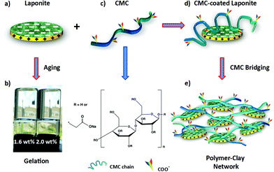 | ||
| Fig. 1 (a) A single LAPONITE® disc with positive charges on the rims and negative charges on the surfaces. (b) Gelation at high clay concentrations (1.6 and 2.0 wt%) due to electrostatic attraction between rims and surfaces.38,39 (c) Chemical structure of CMC. (d) Schematic representation of CMC polymer coating onto individual LAPONITE® surfaces through hydrogen bonding. (e) A homogeneous polymer–clay network in water formed through CMC bridging under the condition of extra CMC. | ||
Transparent films were produce by swiftly mixing separately prepared aqueous solutions of carboxymethyl cellulose (CMC) and LAPONITE®. In Fig. 1 we show a schematic drawing of both the LAPONITE® particles and the CMC. When mixing the clay particles with the CMC chains, hydrogen bonds can form between hydroxyl groups (–OH) on the CMC chains and silanol (Si–O) groups on the negatively charged LAPONITE® surfaces. Here we used carboxymethyl cellulose with a molecular weight of 700 kDa and estimated radius of gyration Rg of around 100 nm,42 which means the diameter of our CMC coils is 8 times larger than the average LAPONITE® diameter. This means a single CMC chain cannot only form several contact points with a single LAPONITE® particle but bridge several particles or wrap completely around one particle, depending on the particle to polymer ratio and the total concentration. Therefore, when the polymer concentration is high enough, the polymer will bridge several LAPONITE® particles and thus form an organic–inorganic highly viscous network. The desired coating method is achieved by first preparing separate clay and polymer solutions, which are then added to each other.
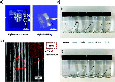
Polymer–clay hybrid suspensions were prepared by mixing a given amount of clay suspension to a 0.8 wt% CMC solution for 24 h under vigorous stirring, thus assuring that all LAPONITE® particles were well dispersed within the polymer solution. The resulting clear, viscoelastic fluids were poured into Petri dishes and left to dry at room temperature (Fig. 2). The films obtained were transparent, freestanding and highly flexible (Fig. 3a). A Scanning Electron Microscope (SEM) image taken from the cross-section of the film showed a multilayered in-plane structure with strong interconnectivity between each layer (Fig. 3b). As evaporation proceeded, the polymer–clay network collapsed like a shrinking sponge due to hydrodynamic interactions.43 Since the drying process was slow, clay particles were given enough time to self-assemble into a three-dimensional “brick-and-mortar” structure similar to that found in nacre, with the reinforcing LAPONITE® particles glued to each other by the soft but toughening CMC. However, as the size of one LAPONITE® disc is too small to be seen by SEM, only a layered structure formed by the polymer–clay network was observed.
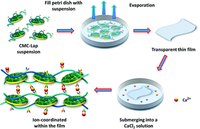 | ||
| Fig. 2 A schematic representation of CMC–Lap hybrid film fabrication via evaporation and then subjected to ion coordination through CMC further chelating with Ca2+ ions. | ||
For the purpose of improving the thermal and mechanical properties, which will be discussed below, we also investigated the effect of the addition of metal ions to the composite films. CMC contains carboxylate ions, which can be chelated with divalent cations (Ca2+ or Mg2+) through ion coordination.44 We used CaCl2 for its ready availability and non-toxicity compared to other divalent metal ions (Cd2+ or Cu2+). Moreover, calcium is also the main constituent of nacre.45 During the preparation, we first cut a small piece of a CMC–Lap film and submerged it in the calcium chloride solution for several minutes (Fig. 2). By doing this, calcium ions were able to infiltrate the nanocomposite films. After the CaCl2 bath, the film was taken out and rinsed with deionised water several times and then dried at room temperature. With the help of energy dispersive X-ray spectroscopy (EDX), we found that the calcium ions, marked by the red regions in Fig. 3b, had been successfully introduced into the hybrid films. It should be noted that pure CMC films immediately dissolved once immersed in calcium chloride solution, so we did not do any tests for calcium-coordinated CMC films. Note that adding the higher-valent cations directly to the initial aqueous polymer–clay mixture leads to a quick gelation and letting the gels dry only leads to turbid, low-quality films.
Water-and thermal-resistance abilities
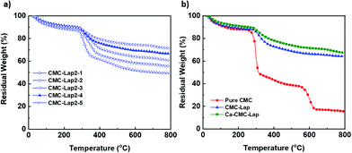
A simple experiment was carried out to compare the films’ stability in water since CMC is a water-soluble polymer. For this, hybrid films with the same size and thickness were immersed in water (Fig. 3c). Before submerging, they were subjected to calcium ion coordination by placing them in a 120 g L−1 CaCl2 solution for different dipping times. Since our nanocomposite films were transparent, we marked their rims black to make them visible in water. Once the normal hybrid film (called CMC–Lap) touched the water, it immediately started to swell while those with ion coordination were still quite rigid initially (Fig. 3c-i). After 20 days, the film with only 1 min dipping time broke into small pieces while all the other films with longer dipping times maintained their original shapes. These experiments demonstrate that a roughly 10 μm thick sample needed only a few minutes of exposure to the CaCl2 solution in order to reach homogenous coordination and thus infiltration of the Ca2+ ions into the entire film. This observation allows us to tune the water resistance of our nanocomposite films against disintegration, which may be of great use in the production of biodegradable materials and coatings. Note that the fully Ca2+-coordinated CMC–Lap films submerged in low and high pH solutions (ranging between pH 2 and 10) also showed no deterioration within 20 days.To also investigate the thermal properties of our nanocomposite films, we performed a thermogravimetric analysis (TGA) for 5 different CMC–Lap weight fraction ratios. The results are shown in Fig. 4. Thermal decomposition of pure CMC generally occurs in two steps (Fig. 4b). The first step is related to weight loss, taking place between 100 and 250 °C, which is due to trapped water removal and the decomposition of the polymer side groups. In the second step between 250 and 600 °C, a further rapid weight loss is associated with the breakdown of the polymer backbone.46,47 As for CMC–Lap2–4 films (CCMC: 0.4 wt%, CLap: 0.8 wt%), the degradation rate decreases while residual weight increases (Fig. 4b), which is assigned to the confinement and thermal protection of CMC against oxidation by the clay particles, which have a naturally high heat resistance. Also, the higher the clay weight fraction, the higher the residual weight due to the higher density of the clay (Fig. 4a). Interestingly, for CMC–Lap hybrid films with calcium ion modification, the degradation rate is further decreased. We ascribe the further increased thermal stability to the incorporation of metal ions into the nanocomposite film. Compared to un-modified films, all those modified with calcium ion (Ca-CMC–Lap) retained a higher residual weight, which we attribute to the addition of the non-volatile calcium ions.
Thin film characterisation
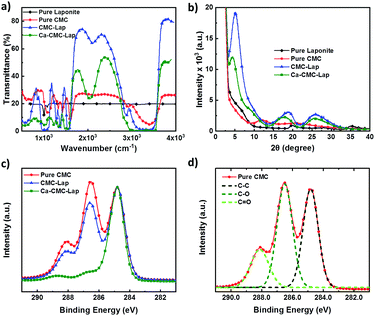
We investigated the molecular interactions between the CMC and clay particles, and the influence of the added Ca2+ ions by performing FTIR spectroscopy (Fig. 5a). Neat LAPONITE® displays two distinct peaks at 950 and 1099 cm−1, which was attributed to the surface Si–O bond stretching.48 The CMC spectrum displayed three characteristic peaks at 1322, 1417 and 1598 cm−1, originating from C–O stretching vibration, symmetrical and asymmetrical C![[double bond, length as m-dash]](https://www.rsc.org/images/entities/char_e001.gif) O stretching vibrations of carboxylate ions respectively.49 The broad and strong transmission band presented at 3403 cm−1 was assigned to an –OH stretching vibration, corresponding to intermolecular and intramolecular hydrogen bonds within the CMC chains.50 However, in the case of our polymer–clay hybrid film, the width of O–H band was broadened with weakened intensity, and the peak position red-shifted from 3403 to 3393 cm−1 compared to pristine CMC. These results suggest weak hydrogen bonding between LAPONITE®'s silanol (Si–O) and CMC's hydroxyl (–OH) groups. In this way, the extent of hydrogen bonds formed between pure CMC was reduced. After calcium ion infiltration, peaks for asymmetrical and symmetrical carboxylate ions both shifted to lower values while the stretching band intensities were slightly weakened, indicating successful coordination of cellulose with calcium ions. Up to this stage, we had already combined the synergistic effect of both hydrogen bonds and ionic bonds.
O stretching vibrations of carboxylate ions respectively.49 The broad and strong transmission band presented at 3403 cm−1 was assigned to an –OH stretching vibration, corresponding to intermolecular and intramolecular hydrogen bonds within the CMC chains.50 However, in the case of our polymer–clay hybrid film, the width of O–H band was broadened with weakened intensity, and the peak position red-shifted from 3403 to 3393 cm−1 compared to pristine CMC. These results suggest weak hydrogen bonding between LAPONITE®'s silanol (Si–O) and CMC's hydroxyl (–OH) groups. In this way, the extent of hydrogen bonds formed between pure CMC was reduced. After calcium ion infiltration, peaks for asymmetrical and symmetrical carboxylate ions both shifted to lower values while the stretching band intensities were slightly weakened, indicating successful coordination of cellulose with calcium ions. Up to this stage, we had already combined the synergistic effect of both hydrogen bonds and ionic bonds.
X-ray diffraction (Fig. 5b) was performed to determine the sub-nanometre structure of the composite films in order to see whether polymer intercalation into the spaces between clay particles was indeed successful. Using Bragg's law, 2d![[thin space (1/6-em)]](https://www.rsc.org/images/entities/char_2009.gif) sin
sin![[thin space (1/6-em)]](https://www.rsc.org/images/entities/char_2009.gif) θ = nλ, where θ is the scattering angle, λ the wavelength of the incoming X-ray beam and n the order, characteristic interlayer distances, d, could be calculated from the peaks of the scattering intensity I(θ) shown in Fig. 5b. In the case of neat clay powder, two broad and weak patterns were observed arising from the small thickness of the clay platelets and their local crystallinity,51 while pristine CMC films displayed two broad peaks in I(θ) with low intensity but different positions, which arise from its semi-crystalline morphology in its dry form.52 For the CMC–Lap nanocomposite film, we observe enhanced peak intensities, which appear to be an overlay of scattering signals due to the pure LAPONITE® and CMC at around 2θ = 18° and 26°, while a much sharper, intense peak appeared at 5.06°, corresponding a characteristic length scale of 1.74 nm. We ascribe this peak to the fact that we indeed enveloped the 1 nm thick LAPONITE® particles with the cellulose chains. Upon drying these will rearrange into the proposed “brick-and-mortar” structure, explaining the apparently increased particle-to-particle distance, which is only weakly hinted by the weak but broad peak at around 6° in the pure LAPONITE® scattering spectrum. It is interesting to observe that after the calcium ion intercalation, the strong first peak further shifted to 2θ = 4.45° (d = 1.98 nm), which agrees with our hypothesis that the Ca2+ ions physically crosslink the CMC chains trapped between the clay particles (see cartoon in Fig. 2). This also explains the additional broadening and shift of the two broad peaks at higher scattering angles seen for the Ca-CMC–Lap scattering curves in Fig. 5b. However, there is also the possibility of the divalent calcium ions to directly bind between two clay platelets held together by the adsorbed polymer as they are negatively charged in water.
θ = nλ, where θ is the scattering angle, λ the wavelength of the incoming X-ray beam and n the order, characteristic interlayer distances, d, could be calculated from the peaks of the scattering intensity I(θ) shown in Fig. 5b. In the case of neat clay powder, two broad and weak patterns were observed arising from the small thickness of the clay platelets and their local crystallinity,51 while pristine CMC films displayed two broad peaks in I(θ) with low intensity but different positions, which arise from its semi-crystalline morphology in its dry form.52 For the CMC–Lap nanocomposite film, we observe enhanced peak intensities, which appear to be an overlay of scattering signals due to the pure LAPONITE® and CMC at around 2θ = 18° and 26°, while a much sharper, intense peak appeared at 5.06°, corresponding a characteristic length scale of 1.74 nm. We ascribe this peak to the fact that we indeed enveloped the 1 nm thick LAPONITE® particles with the cellulose chains. Upon drying these will rearrange into the proposed “brick-and-mortar” structure, explaining the apparently increased particle-to-particle distance, which is only weakly hinted by the weak but broad peak at around 6° in the pure LAPONITE® scattering spectrum. It is interesting to observe that after the calcium ion intercalation, the strong first peak further shifted to 2θ = 4.45° (d = 1.98 nm), which agrees with our hypothesis that the Ca2+ ions physically crosslink the CMC chains trapped between the clay particles (see cartoon in Fig. 2). This also explains the additional broadening and shift of the two broad peaks at higher scattering angles seen for the Ca-CMC–Lap scattering curves in Fig. 5b. However, there is also the possibility of the divalent calcium ions to directly bind between two clay platelets held together by the adsorbed polymer as they are negatively charged in water.
The physical binding between the polymer and the nanoparticle and the role of the Ca2+ ions within the dried films were further studied with X-ray photoelectron spectroscopy (XPS; Fig. 5c and d). Typically, pure CMC displays 3 peaks at ∼284.8 eV, 286 eV and 288.5 eV, which can be attributed to C–C, C–O, and C![[double bond, length as m-dash]](https://www.rsc.org/images/entities/char_e001.gif) O bonds respectively (Fig. 5d).53,54 The C 1s core-level XPS spectrum (Fig. 5c) of a composite CMC–Lap film reveals an apparent decrease in C–O signals compared to that of a pure CMC film, indicating the successful formation of the intermolecular hydrogen bonding between polymers and nanoparticles. The peak shift and a prominent signal decrease of the C
O bonds respectively (Fig. 5d).53,54 The C 1s core-level XPS spectrum (Fig. 5c) of a composite CMC–Lap film reveals an apparent decrease in C–O signals compared to that of a pure CMC film, indicating the successful formation of the intermolecular hydrogen bonding between polymers and nanoparticles. The peak shift and a prominent signal decrease of the C![[double bond, length as m-dash]](https://www.rsc.org/images/entities/char_e001.gif) O signal in the ion-coordinated film is due to the successful intercalation of calcium ions into the carboxyl groups in CMC biopolymers.
O signal in the ion-coordinated film is due to the successful intercalation of calcium ions into the carboxyl groups in CMC biopolymers.
Optical, mechanical and fire-retardant properties
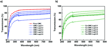
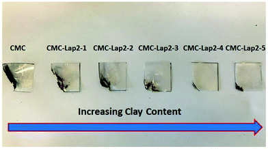
Having established the local structure of our ion-coordinated nanocomposite films, we now present measurements testing the films’ optical and mechanical properties as a function of the clay-to-polymer ratio. First, we measured the transparency of the hybrid films using UV-vis spectroscopy (Fig. 6a). The light transmittance of pure CMC was 85% at 650 nm. With the increase of clay to polymer ratio, the light transmittance slightly decreased especially for a CMC to LAPONITE® ratio of 2![[thin space (1/6-em)]](https://www.rsc.org/images/entities/char_2009.gif) :
:![[thin space (1/6-em)]](https://www.rsc.org/images/entities/char_2009.gif) 5 (CMC–Lap2–5). This decrease can easily be understood when considering the reflectance of the film in air:
5 (CMC–Lap2–5). This decrease can easily be understood when considering the reflectance of the film in air:| R = |(1 − n)/(1 + n)|2 |
It should be noted that when sandwiched between crossed polarizer and analyser the films showed no birefringence. However, when placing the films under an angle, some light was transmitted, supporting our view that we have some smectic (layered) order in the films.
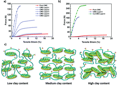
We also carried out tensile tests for our films whose results are summarised in Table 1. Applied tensile force vs. strain measurement results presented in Fig. 7a show that the pure CMC film initially exhibited a linear elastic deformation before displaying a large plastic deformation region at low tensile stress. When the clay content was comparatively low (CMC–Lap2–1 to CMC–Lap2–2), the ability of the films to endure tensile force (and also force per unit cross-sectional area) was enhanced remarkably. For the nanocomposites with higher clay content (CMC–Lap2–2 to CMC–Lap2–4), the mechanical properties improved further but at lower increasing rate. Indeed, the CMC–Lap2–4 films seemed to reach an optimal polymer–clay ratio as the force–tensile strain plots indicate. Increasing the LAPONITE® content even further finally lead to poorer mechanical properties (see curve for CMC–Lap2–5 in Fig. 7a). It is interesting to note that in contrast to the pure CMC films the hybrid films showed an increasingly shorter plastic region before sudden fracture, which occurred at around 4% applied tensile strain in the CMC–Lap2–4 sample.
| Samples | Thickness (mm) | Cross-sectional area (mm2) | Maximum force (N) | Maximum force per unit cross-sectional area (N mm−2) |
|---|---|---|---|---|
| CMC | 0.01 | 0.15 | 15.5 (± 0.8) | 103.3 (± 5.2) |
| CMC–Lap2–1 | 0.01 | 0.15 | 18.4 (± 0.9) | 122.7 (± 6.1) |
| CMC–Lap2–2 | 0.02 | 0.30 | 52.3 (± 0.8) | 174.2 (± 8.7) |
| CMC–Lap2–3 | 0.03 | 0.45 | 90.7 (± 4.5) | 201.6 (± 10.0) |
| CMC–Lap2–4 | 0.05 | 0.75 | 169.5 (± 8.5) | 225.9 (± 11.3) |
| CMC–Lap2–5 | 0.06 | 0.90 | 125.5 (± 6.1) | 139.5 (± 7.0) |
| Ca-CMC–Lap2–4 | 0.06 | 0.90 | 268.2 (± 13.4) | 298.0 (± 0.15) |
To understand the change in the elastic and plastic regions of the pure polymer and the composite films one needs to remember that the pure CMC film is in fact a highly entangled polymer melt. Hence the strong plasticity over a large range of deformation (tensile strain) before the sudden rupture of the film occurs. The strength at lower deformations on the other hand comes from the intermolecular and intramolecular hydrogen bonding between segments of the CMC chains, which are of the order of the thermal energy kBT or smaller.56 However, when adding clay particles into the polymer matrix the degree of entanglement and therefore the range of plasticity will go down, while the adsorption to the clay particles and thus the increasingly strong bridging between them leads to reinforcing the strength of our hybrid films (Fig. 7c). Therefore, compared to pure CMC films, more energy is required to break the hydrogen bonds at the polymer–clay interface inducing interlayer slippage, acting like a chemical cross-linker, than for the disentanglement between the polymer chains.57 Our measurements suggest that the polymer-to-clay ratio reached in the CMC–Lap2–4 samples delivers the maximum number of polymer-to-clay contacts (cross-links) in terms of perfect coating that delivers the best mechanical strength, similar to the “brick-and-mortar” structure found in nacre.58 If using too much clay (CMC–Lap2–5), we run out of polymeric mortar to hold the platelets together through adhesion and bridging, and if too few of the bricks are used the composite films will be dominated by the plastic behaviour of polymer melts (CMC–Lap2–3 and lower ratios). To this end, the molecular weight MW of the CMC plays an additional role. When chosen too small (while keeping the same clay-to-polymer ratio) the mechanical strength of the films is reduced, supporting our hypothesis that the entanglements between CMC chains are important. Choosing a larger MW on the other hand renders the initial CMC solution even more viscoelastic leading to less homogenous CMC–Lap mixtures and less smooth films.
Having identified the CMC–Lap2–4 as the ideal mixture for making artificial nacre, we chose this composite film to study the effect of the calcium-ion coordination. Indeed, after dipping a CMC–Lap2–4 film into a CaCl2 solution for 5 minutes and letting it dry, such modified films showed an even stronger resistance to tensile force, which is 2.3 times that of nacre (Fig. 7b).9,59 Even the plasticity range increased slightly. We suggest that this further improved mechanical behaviour derives from the additional coordination bonding between the polymer and the calcium ion as well as the binding between two negatively charged platelets by the Ca2+ ions that need to be broken when subjected to external force. This suggests that ion coordination is able to further enhance the mechanical properties of our nanocomposite films while combining high strength and toughness at the same time.
Finally, we tested the CMC–Lap composite films as possible fire-retardant coating of PET (polyethylene terephthalate) films, since PET is a very combustible resin that is widely used in people's daily lives.60 A very thin layer of hybrid film was coated onto both sides of PET films. The fire resistance ability was then estimated by burning these coated PET films. Upon exposing a corner of the coated film for 5 seconds to a Bunsen-burner flame, PET films coated only with cellulose burned with vigorous flames and dripped badly (Fig. 8). However, PET films with nanocomposite coating demonstrated improved fire-retardant ability. During the exposure to a direct flame, the film burnt initially only for a very short time because of small amount of polymers attached on the clay particles. After this, the specimen gradually became black, due to carbonization of the CMC.61 When the surface polymer finished burning out, the remaining clay particles did not catch any fire and remained inert. It is noteworthy that, unlike plastic materials, no dripping of hot fluids happened during the burning process. With increasing clay contents in the nanocomposite film coating, the charred mass decreased along with less burning time and better-maintained dimension. As the clay content further increased, a completely different phenomenon occurred. The flame self-extinguished right after its removal and the coated PET could hardly be ignited. The reason for this outstanding fire-retardant property can be assigned to the densely packed layers of the inorganic clay particles. In general clays are known to be highly heat resistant and are excellent heat insulators that have been used for that matter in polymer–clay nanocomposites in the past.62,63 Notably, many studies used the natural clay montmorillonite in combination of carbon nanotubes or graphene embedded in resin or synthetic polymers.62–67 Closer to our approach, Ge et al. used magadiite and chitosan to fabricate nanocomposite membranes using a water-evaporation-induced self-assembly method.68 The fire resistance of their membranes comes from the silane coupling agent γ-aminopropyltriethoxysilane and the large number of Si–OH groups, which can produce water during burning. The composite has low transparency due to the addition of chitosan. To our knowledge LAPONITE® has not yet been combined with CMC. The advantage of our system is its transparency. Moreover, we show that choosing the optimal polymer–clay ratio we can obtain improved coatings that can efficiently increase the thermal energy dissipation and suppress the transport of heat and oxygen, which can then effectively protect the fresh PET film inside the coating.
To summarize, Ca2+-doped CMC–LAPONITE® composite films show remarkable optical transparency in the UV-vis range, mechanical strength and heat resistance, which can be utilized in the development of thin coatings that are environmentally friendly in production and recycling. Intriguingly, testing these different optical and mechanical properties by exposing the CMC–Lap films to solutions with other-valent cations such as Fe2(SO4)3, AlCl3, MgCl2 and KCl, their transparency, smoothness and mechanical properties became inferior. Testing also different bio-polymers (sodium alginate (SA), xanthan, chitosan and other cellulose derivatives) as the mortar between our clay-bricks did not deliver such superior, tuneable properties as the CMC–Lap system. It is noteworthy that LAPONITE®–PEO and LAPONITE®–(SA) films could be prepared and did appear transparent.
Conclusions
In this paper, we have demonstrated a simple pathway to fabricate superior bio-mimetic, sustainable nanocomposite films resembling the structure of nacre but on nanoscale. These films are composed of the natural materials carboxymethyl cellulose and LAPONITE® nanodiscs. Through hydrogen bonding, the much longer polymers can attach to the clay surfaces thus forming trains of adsorption points on opposing clay particles leading to bridging inside the films with well-aligned architecture combined with a glass-like transparency and high flexibility. FTIR, XRD and XPS analysis proved that cellulose has been successfully intercalated between LAPONITE® particles. By choosing the appropriate polymer-to-clay ratio we were able to obtain a “perfect three dimensional brick-and mortar” structure that leads to very high toughness while the films remained transparent and flexible. The mechanical properties were further enhanced by intercalating Ca2+ ions between the clay particles, at the expense of maximum elastic strain. These results indicate that our hybrid films show superior resistance against tensile forces than other nacre-inspired materials with the same inorganic content. The outstanding mechanical properties were supplemented by fire-retardant properties when used as protective coatings. Furthermore, the Ca2+ treated nanocomposite films showed a tuneable resistance to dissolution in acidic and basic solution. We believe that in the near future, the scalable and environmentally friendly strategy along with the integrated high performance make these nanocomposite materials promising candidates in different fields like transportation, wearable electronic devices, artificial muscles, aerospace and food packaging industries. In particular, their potential as flexible coatings could be of great benefit.Experimental
Materials
LAPONITE® XLG (Lap) was provided by Rock Additives. Sodium carboxymethyl cellulose (CMC) with a molecular weight of 700 kDa and degree of substitution of 0.75 was purchased from Sigma Aldrich. The refractive index of CMC is 1.47. Anhydrous calcium chloride (CaCl2) was also obtained from Sigma Aldrich. All materials were analytical grade and used as received. All solutions were prepared using Milli-Q water.Preparation of LAPONITE® and cellulose dispersions
A clear 0.8 wt% cellulose solution was prepared by dispersing cellulose powder into water, followed by a mild stirring for 12 h at 90 °C. Separately, LAPONITE® suspensions with varying concentrations (0.4, 0.8, 1.2, 1.6 and 2.0 wt%) were prepared by adding a specific amount of dry LAPONITE® powder into deionised water.32,33 The LAPONITE® powder was always stored in a desiccator in order to maintain reproducibility. Note that LAPONITE® suspensions with higher concentrations were not prepared because they quickly aggregated and gelled within a short time.32 In order to fully disperse the LAPONITE® powder in water, the solutions were vigorously stirred for 24 hours, and then filtered using a Millipore Syringe filter (from Sigma Aldrich) with a pore size of 0.22 μm.Preparation of CMC–LAPONITE® nanocomposite films
Our nanocomposite films were prepared in two steps. First, the clay suspension (5 mL) with specific concentration (0.4, 0.8, 1.2, 1.6 and 2.0 wt%) was added gradually into each cellulose dispersion (0.8 wt%, 5 mL) to form hybrids with CMC–LAPONITE® weight ratios ranging from 2–1 to 2–5, named as CMC–Lap2–1, CMC–Lap2–2, CMC–Lap2–3, CMC–Lap2–4, CMC–Lap2–5, respectively. Subsequently the samples were subjected to magnetic stirring for 24 hours followed by an ultrasonic bath for 15 min for the purpose of removing air bubbles formed during mixing. As a control, a pure cellulose sample was prepared by diluting a 5 mL CMC (0.8 wt%) suspension with 5 mL deionised water to reach a polymer concentration of 0.4 wt%. In the second step, all hybrids were transferred into Petri dishes and allowed to evaporate at room temperature for 48 hours. When evaporation finished, films were carefully peeled off from the Petri dishes.Preparation of Ca-CMC nanocomposite films
Dry films were cut into small strips (15 × 30 mm) and submerged into 120 g L−1 calcium chloride solution. When finishing this, these calcium-ion-modified nanocomposite films were taken out and washed five times with deionised water and further dried at ambient conditions for 12 hours.Characterisation
The cross-sectional morphology of nanocomposite films was first coated with a conducting layer by sputtering it with a thin Au layer (3 nm thick) and then imaged with a SEM using a ZEISS Gemini EM with a build in energy dispersive X-ray spectroscopy (EDX) mode at an accelerating voltage of 10 kV. The sub-nanometer structure of the nanocomposite films was measured by XRD using a PANalytical Empyrean Series 2 Diffractometer System equipped with Cu Kα radiation (λ = 1.54 Å) at 20 kV and 5 mA. FTIR examinations were carried out using a NICOLET iS10 FTIR spectrometer in the range of 500 to 4000 cm−1. XPS was conducted using an AXIS SUPRA photoelectron spectrometer (Kratos Analytical Ltd, UK) with a monochromatic Al Kα (hv = 1486.6 eV) X-ray source for excitation. The light transmittance of nanocomposite films was measured with a Cary 300 UV-Vis-NIR spectrometer. Thermal gravimetric analysis (TGA) was performed on a PerkinElmer Pyris 1 instrument, under nitrogen atmosphere with a heating rate of 20 °C min−1 from 100 to 800 °C. The mechanical properties of the nanocomposite films and the reference polymer films were measured using a universal mechanical tensile tester (Instron 5500R-6025) equipped with a 200 N load cell at ambient conditions. For the mechanical testing, the films were first cut with scissors into rectangular strips of length 30 mm and width 15 mm. The film thickness (10–50 μm) was measured with a calliper. Then the films were mounted using tension clamps. The distance between the clamps was set to be 5 mm and a nominal loading rate of 0.5 mm min−1 was applied. Five specimens were tested for each type of film to ensure the reproducibility (with error bars of about ±5%).Conflicts of interest
There are no conflicts of interest to declare.Acknowledgements
We thank the Winton Program for the Physics of Sustainability for financial support. TE acknowledges the Royal Society for support via a Newton International Fellowship. We thank Linjie Dai for technical support on TEM and Zewei Li for doing the XRD measurements. We thank Thomas O’Neill for valuable discussions on interpreting the FTIR results.References
- R. A. Gross and B. Kalra, Science, 2002, 297, 803–807 CrossRef CAS PubMed.
- C. Silvestre, D. Duraccio and S. Cimmino, Prog. Polym. Sci., 2011, 36, 1766–1782 CrossRef CAS.
- H. Gao, B. Ji, I. L. Jager, E. Arzt and P. Fratzl, Proc. Natl. Acad. Sci. U. S. A., 2003, 100, 5597–5600 CrossRef CAS PubMed.
- P. Fratzl, H. S. Gupta, F. D. Fischer and O. Kolednik, Adv. Mater., 2007, 19, 2657–2661 CrossRef CAS.
- P. Fratzl and R. Weinkamer, Prog. Mater. Sci., 2007, 52, 1263–1334 CrossRef CAS.
- T. M. Casey, B. Joos, T. D. Fitzgerald, M. E. Yurlina and P. A. Young, Physiol. Zool., 1988, 61, 377 Search PubMed.
- G. Mayer, Science, 2005, 310, 1144–1147 CrossRef CAS PubMed.
- F. Barthelat and H. D. Espinosa, Exp. Mech., 2007, 47, 311–324 CrossRef.
- R. Z. Wang, Z. Suo, A. G. Evans, N. Yao and I. A. Aksay, J. Mater. Res., 2001, 16, 2485–2493 CrossRef CAS.
- A. Y. M. Lin and M. A. Meyers, J. Mech. Behav. Biomed. Mater., 2009, 2, 607–612 CrossRef PubMed.
- F. Song, A. K. Soh and Y. L. Bai, Biomaterials, 2003, 24, 3623–3631 CrossRef CAS PubMed.
- X. Li, Z. H. Xu and R. Wang, Nano Lett., 2006, 6, 2301–2304 CrossRef CAS PubMed.
- S. Wan, Y. Li, J. Peng, H. Hu, Q. Cheng and L. Jiang, ACS Nano, 2015, 9, 708–714 CrossRef CAS PubMed.
- A. Di Mauro, M. Cantarella, G. Nicotra, G. Pellegrino, A. Gulino, M. V. Brundo, V. Privitera and G. Impellizzeri, Sci. Rep., 2017, 7, 1–12 CrossRef PubMed.
- Y. Zhang, S. Zhuang, X. Xu and J. Hu, Opt. Mater., 2013, 36, 169–172 CrossRef CAS.
- L. J. Bonderer, A. R. Studart and L. J. Gauckler, Science, 2008, 319, 1069–1073 CrossRef CAS PubMed.
- J. Zhu, C. M. Andres, J. Xu, A. Ramamoorthy, T. Tsotsis and N. A. Kotov, ACS Nano, 2012, 6, 8357–8365 CrossRef CAS PubMed.
- R. Liu, S. Liang, X.-Z. Tang, D. Yan, X. Li and Z.-Z. Yu, J. Mater. Chem., 2012, 22, 14160 RSC.
- Y. Shu, P. Yin, B. Liang, H. Wang and L. Guo, ACS Appl. Mater. Interfaces, 2014, 6, 15154–15161 CrossRef CAS PubMed.
- R. Chen, C-an Wang, Y. Huang and H. Le, Mater. Sci. Eng., C, 2008, 28, 218–222 CrossRef CAS.
- P. Podsiadlo, A. K. Kaushik, E. M. Arruda, A. M. Waas, B. S. Shim, J. Xu, H. Nandivada, B. G. Pumplin, J. Lahann, A. Ramamoorthy and N. A. Kotov, Science, 2007, 318, 80–83 CrossRef CAS PubMed.
- S. Gong, M. Wu, L. Jiang and Q. Cheng, Mater. Res. Express, 2016, 3, 1–7 Search PubMed.
- G. D. Zhan, J. D. Kuntz, J. Wan and A. K. Mukherjee, Nat. Mater., 2003, 2, 38–42 CrossRef CAS PubMed.
- E. Günister, D. Pestreli, C. H. Ünlü, O. Atici and N. Güngör, Carbohydr. Polym., 2007, 67, 358–365 CrossRef.
- P. Xu, Y. Lan, Z. Xing and E. Eiser, Soft Matter, 2018, 14, 2782–2788 RSC.
- K. Brandt, M. F. H. Wolff, V. Salikov, S. Heinrich and G. A. Schneider, Sci. Rep., 2013, 3, 1–8 Search PubMed.
- P. Zhang, H. Li, J. Shi and J. Lu, RSC Adv., 2016, 6, 94739–94747 RSC.
- S. Deville, E. Saiz, R. K. Nalla and A. P. Tomsia, Science, 2006, 311, 515–518 CrossRef CAS PubMed.
- T. H. Lin, W. H. Huang, I. K. Jun and P. Jiang, Chem. Mater., 2009, 21, 2039–2044 CrossRef CAS.
- A. Lopez-Galindo and C. Viseras, Pharmaceutical and Cosmetic Applications of Clays, Elsevier, 2004, pp. 267–289 Search PubMed.
- B. Ruzicka and E. Zaccarelli, Soft Matter, 2011, 7, 1268 RSC.
- S. Jabbari-Farouji, E. Eiser, G. H. Wegdam and D. Bonn, J. Phys.: Condens. Matter, 2004, 16, L471–L477 CrossRef CAS.
- S. Jabbari-Farouji, D. Mizuno, M. Atakhorrami, F. C. MacKintosh, C. F. Schmidt, E. Eiser, G. H. Wegdam and D. Bonn, Phys. Rev. Lett., 2007, 98, 108302 CrossRef PubMed.
- Z. P. Bazant, Scaling of structural strength, Elsevier, 2005 Search PubMed.
- D. Klemm, B. Heublein, H.-P. Fink and A. Bohn, Angew. Chem., Int. Ed., 2005, 44, 3358–3393 CrossRef CAS PubMed.
- E. Grządka and S. Chibowski, Cellulose, 2012, 19, 23–36 CrossRef.
- M. Nara, H. Torii and M. Tasumi, J. Phys. Chem., 1996, 100, 19812–19817 CrossRef CAS.
- R. Russo, M. Malinconico and G. Santagata, Biomacromolecules, 2007, 8, 3193–3197 CrossRef CAS PubMed.
- J. Y. Sun, X. Zhao, W. R. K. Illeperuma, O. Chaudhuri, K. H. Oh, D. J. Mooney, J. J. Vlassak and Z. Suo, Nature, 2012, 489, 133–136 CrossRef CAS PubMed.
- B. Ruzicka and E. Zaccarelli, Soft Matter, 2011, 7, 1268 RSC.
- A. Mourchid and P. Levitz, Phys. Rev. E: Stat. Phys., Plasmas, Fluids, Relat. Interdiscip. Top., 1998, 57, 4887–4890 CrossRef.
- C. W. Hoogendam, A. De Keizer, M. A. Cohen Stuart, B. H. Bijsterbosch, J. A. M. Smit, J. A. P. P. Van Dijk, P. M. Van Der Horst and J. G. Batelaan, Macromolecules, 1998, 31, 6297–6309 CrossRef CAS.
- M. M. Malwitz, A. Dundigalla, V. Ferreiro, P. D. Butler, M. C. Henk and G. Schmidt, Phys. Chem. Chem. Phys., 2004, 6, 2977 RSC.
- A. K. Katz, J. P. Glusker, S. A. Beebe and C. W. Bock, J. Am. Chem. Soc., 1996, 118, 5752–5763 CrossRef CAS.
- F. Barthelat, Science, 2016, 354, 32–33 CrossRef CAS PubMed.
- R. Xing, X. Wang, C. Zhang, J. Wang, Y. Zhang, Y. Song and Z. Guo, J. Mater. Chem., 2011, 21, 11142 RSC.
- W. P. F. Neto, H. A. Silvério, J. G. Vieira, H. da Costa e Silva Alves, D. Pasquini, R. M. N. de Assunção and N. O. Dantas, Macromol. Symp., 2012, 319, 93–98 CrossRef.
- Y. Liu and B. P. Lee, J. Mater. Chem. B, 2016, 4, 6534–6540 RSC.
- M. S. A. Rani, S. Rudhziah, A. Ahmad and N. S. Mohamed, Polymers, 2014, 6, 2371–2385 CrossRef.
- A. Sadiasa, R. A. Franco, H. S. Seo and B. T. Lee, J. Biomed. Sci. Eng., 2013, 6, 987–995 CrossRef.
- Y. Yao, Z. Li and H. Li, RSC Adv., 2015, 5, 70868–70873 RSC.
- S. Vimalraj, S. Saravanan, M. Vairamani, C. Gopalakrishnan, T. P. Sastry and N. Selvamurugan, Int. J. Biol. Macromol., 2016, 93, 1457–1464 CrossRef CAS PubMed.
- D. M. Kalaskar, R. V. Ulijn, J. E. Gough, M. R. Alexander, D. J. Scurr, W. W. Sampson and S. J. Eichhorn, Cellulose, 2010, 17, 747–756 CrossRef CAS.
- K. Kolářová, V. Vosmanská, S. Rimpelová and V. Švorčík, Cellulose, 2013, 20, 953–961 CrossRef.
- B. S. Neumann, Clay Miner., 1971, 9, 231–243 CrossRef CAS.
- H. Zhu, S. Zhu, Z. Jia, S. Parvinian, Y. Li, O. Vaaland, L. Hu and T. Li, Proc. Natl. Acad. Sci. U. S. A., 2015, 112, 8971–8976 CrossRef CAS PubMed.
- G. E. Padawer and N. Beecher, Polym. Eng. Sci., 1970, 10, 185–192 CrossRef CAS.
- Y. Shao, H. P. Zhao, X. Q. Feng and H. Gao, J. Mech. Phys. Solids, 2012, 60, 1400–1419 CrossRef.
- F. Barthelat, C. M. Li, C. Comi and H. D. Espinosa, J. Mater. Res., 2006, 21, 1977–1986 CrossRef CAS.
- S. V. Levchik and E. D. Weil, Polym. Adv. Technol., 2004, 15, 691–700 CrossRef CAS.
- F. Carosio, J. Kochumalayil, F. Cuttica, G. Camino and L. Berglund, ACS Appl. Mater. Interfaces, 2015, 7, 5847–5856 CrossRef CAS PubMed.
- H. Almasi, B. Ghanbarzadeh and A. A. Entezami, Int. J. Biol. Macromol., 2010, 46, 1–5 CrossRef CAS PubMed.
- D. Makwana, J. Castano, R. S. Somani and H. C. Bajaj, Arabian J. Chem., 2020, 13, 3092–3099 CrossRef CAS.
- Z. Zhao, J. Gou, S. Bietto, C. Ibeh and D. Hui, Compos. Sci. Technol., 2009, 69, 2081–2087 CrossRef CAS.
- B. M. Kunkel, B. C. Peoples, C. M. Yung and S. L. Scott, Macromol. Mater. Eng., 2011, 296, 1075–1080 CrossRef CAS.
- Y. S. Kim, R. Harris and R. Davis, ACS Macro Lett., 2012, 1, 820–824 CrossRef CAS.
- P. Ming, Z. Song, S. Gong, Y. Zhang, J. Duan, Q. Zhang, L. Jiang and Q. Cheng, J. Mater. Chem. A, 2015, 3, 21194–21200 RSC.
- M. Ge, X. Wang, M. Du, G. Liang, G. Hu and A. S. M. Jahangir, Materials, 2019, 12, 173 CrossRef CAS PubMed.
| This journal is © The Royal Society of Chemistry 2020 |

