
 Open Access Article
 This Open Access Article is licensed under a
 Creative Commons Attribution 3.0 Unported Licence
Stabilization of Li–S batteries with a lean electrolyte via ion-exchange trapping of lithium polysulfides using a cationic, polybenzimidazolium binder†
Chuyen Van
Pham
 *ab,
Lili
Liu
b,
Benjamin
Britton
f,
Michael
Walter
be,
Steven
Holdcroft
f and
Simon
Thiele
*acd
*ab,
Lili
Liu
b,
Benjamin
Britton
f,
Michael
Walter
be,
Steven
Holdcroft
f and
Simon
Thiele
*acd
aElectrochemical Energy Systems, IMTEK – Department of Microsystems Engineering, University of Freiburg, Georges-Koehler-Allee 103, 79110 Freiburg, Germany. E-mail: chuyen.pham@imtek.uni-freiburg.de
bInstitute, Freiburg Center for Interactive Materials and Bioinspired Technologies (FIT), University of Freiburg, Georges-Köhler-Allee 105, 79110 Freiburg, Germany
cForschungszentrum Jülich GmbH, Helmholtz-Institute Erlangen-Nürnberg for Renewable Energy (IEK-11), Forschungszentrum Jülich, Egerlandstr. 3, 91058 Erlangen, Germany
dDepartment of Chemical and Biological Engineering, Friedrich-Alexander-Universität Erlangen-Nürnberg, Egerlandstr. 3, 91058 Erlangen, Germany. E-mail: si.thiele@fz-juelich.de
eFraunhofer IWM, Wöhlerstrasse 11, D-79108 Freiburg i. Br., Germany
fDepartment of Chemistry, Simon Fraser University, 8888 University Drive, Burnaby, V5A-1S6, Canada
First published on 5th December 2019
Abstract
Implementing Li–S cells using high S loading and lean electrolyte content is considered the only viable way to achieve competitive specific energy for practical applications. However, under these conditions, the cell cycle life and performance are drastically reduced due to the severe polysulfide shuttle effect, electrolyte depletion, and sluggish electrochemical S conversion. Here we demonstrate that a cationic polymer binder can efficiently mitigate the polysulfide shuttle effect. The employed cationic polymer, poly[2,2′-(2,2′′,4,4′′,6,6′′-hexamethyl-p-terphenyl-3,3′′-diyl)-5,5′-bibenzimidazolium iodide] (HMT-PMBI(I−)), possesses abundant benzimidazolium cations which interact with dissolved polysulfide anions when used as an active binder. Simultaneously, density functional theory calculations show that HMT-PMBI+ loosely binds with TFSI− and Li+, allowing HMT-PMBI(I−) to exchange its I− anion with TFSI− from the electrolyte salt to form HMT-PMBI(TFSI) containing loosely bound Li+. This forms a Li+ conducting phase within the cathode, allowing a reduced electrolyte content. Therefore, the novel active binder enables a stable cyclability of >440 cycles for Li–S batteries with relatively high S-loading (3–4 mg cm−2) and a lean electrolyte content of 6 μl mgS−1. As the cells prepared in this work use inexpensive, commercially available materials and a conventional doctor-blade fabrication approach, the results are highly relevant to practical applications.
1. Introduction
Batteries are nowadays indispensable components in industrial applications such as portable electronic devices and power sources in electric vehicles. Currently, the rechargeable Li-ion battery is the dominant battery type.1,2 Electrified automobiles are considered the best solution to decrease environmental pollution in the transport sector. To enable the market penetration of electric vehicles, a driving range of at least 500 km is required as well as a further reduction in battery costs. This requires batteries with energy densities of ≥400 W h kg−1, whereas current Li-ion batteries exhibit values of 200–250 W h kg−1, approaching their limit.3 A promising candidate which meets the above requirements is the Li–S battery, which has a theoretical energy density of ∼2600 W h kg−1 – which is >four times that of Li-ion cells (∼600 W h kg−1).3 Furthermore, sulfur is abundant, inexpensive, and non-toxic.3,4 However, the commercialization of Li–S batteries has been obstructed due to their technical deficiencies.5 These include a short cycle life resulting from the loss of active material caused by the shuttle effect involving the dissolution of higher-order polysulfides (e.g., Li2S8, Li2S6, and Li2S4) in the cell electrolyte. Also, the conversion reactions, S ⇄ Li2S, cause a >75% volume expansion/contraction which leads to their disintegration.6 The low electrical conductivity (10−30 S cm−1) of polysulfur (S8) and the discharge products (e.g. Li2S and Li2S2) further limits both S utilization and battery rate capability.7 To address these obstacles, Nazar and coworkers8 introduced the concept of using highly ordered, mesoporous carbon to confine sulfur and polysulfides. These S cathode structures were found to substantially enhance the cycle life and charge capacity and revived the interest in Li–S battery technology. Since then conductive carbonaceous matrixes have been widely investigated as host materials for sulfur in S-cathodes.8–12 High cell performances are now achievable with specific capacities approaching theoretical values13,14 and a cycle life of >1000 cycles.15,16 Nevertheless, high cell performances have been obtained largely based on low loadings of sulfur (e.g., <2 mg cm−2) and high contents of carbon.17 Moreover, large amounts of electrolyte per S mass (e.g., E/S > 10 μl mgS−1, flooded electrolyte) are often used to fill the cathode pores and form percolation pathways for the electrolyte.18 Based on calculations for a Li–S cell with appropriate parameters, it is noted that the specific energy of Li–S batteries surpasses that of Li-ion analogs only if the electrolyte content is <7 μl mgS−1 and the S-loading is >4 mg cm−2.19 Unfortunately, conventional Li–S cells usually require an electrolyte content E/S of >10 μl mgS−1 for appropriate electrochemical conversion of S and discharge products, based on the mechanism of dissolution of polysulfides.20 Due to the low electrical and ion conductivity of S8, it is necessary that S8 dissolves in the electrolyte and diffuses to the electron conducting surface, where electrochemical reactions occur at the interface between the host surfaces (electron-conducting phase) and liquid electrolyte (Li+ conducting phase). Furthermore, the electrolyte is consumed via reaction with the Li metal anode during cycling. Therefore, reducing the electrolyte content while maintaining the Li–S cell performance and cyclability with high S-loadings appears to be the only viable way for Li–S batteries to compete with the current Li-ion batteries. Unfortunately, this is the most challenging aspect facing Li–S battery development.17,21 Yang et al.22 reported the incorporation of MoP nanoparticles in a S-host as the electrocatalyst in order to accelerate the S-conversion kinetics for the Li–S cell using S-loadings of 6 mg cm−2 and lean E/S ratios of 4 μl mgS−1. The cell achieved an areal capacity of ∼5 mA h cm−2 and 50 cycle durability. Using intercalation–conversion hybrid cathodes of S8 and Mo6S8, Xue et al.23 demonstrated Li–S cells with an E/S ratio of 1.5 μl mgS−1, delivering a gravimetric energy density of ∼400 W h kg−1 at the first cycle and at ∼300 W h kg−1 after approximately 50 cycles at the cell level. Liu and co-workers developed a swellable PEO10LiTFSI polymer gel as a reservoir to trap Sx2−, reporting Li–S cells with E/S ratios of up to 3.3 μl mgS−1 to produce a capacity of 4.6 mA h cm−2. Recently, the strategy of using a large-sized S-host was used to demonstrate Li–S cells with a capacity of ∼5 mA h cm−2 at the first cycle and of ∼3 mA h cm−2 after 250 cycles using a S-loading of 5 mg cm−2 and E/S of 7 μl mgS−1.24 The above are noteworthy developments that focus on lean electrolytes and high S-loadings for Li–S batteries. However, the lean electrolyte conditions exacerbate the instability of Li–S cells; as a result, a satisfactory cycle life has not been realized.Here, we report the application of a cationic polymer, poly[2,2′-(2,2′′,4,4′′,6,6′′-hexamethyl-p-terphenyl-3,3′′-diyl)-5,5′-bibenzimidazolium iodide] (HMT-PMBI(I−)),25 as an active bifunctional binder for Li–S batteries. On the one hand, the cationic polymer efficiently traps dissolved anionic polysulfides within S cathodes by their interaction with benzimidazolium units of HMT-PMBI+ as illustrated in Fig. 1. On the other hand, HMT-PMBI+ loosely binds TFSI− and Li+, forming a Li+ conducting phase within the cathode, allowing for a reduced electrolyte content. The incorporation of HMT-PMBI in Li–S coin cells resulted in a substantially enhanced cycle life compared to that of control cells that incorporate the conventional PVDF binder. The new active binder enables a stable cyclability of >440 cycles for Li–S batteries with relatively high S-loading (3–4 mg cm−2) and a lean electrolyte content of 6 μl mgS−1 using conventional aluminum current collectors. Moreover, this strategy circumvents the use of a traditional polyvinylidene difluoride (PVDF) binder which has a poor affinity for polysulfides and yields mechanically unstable electrodes with high loadings of sulfur.26
 | ||
| Fig. 1 Schematic illustration of ionic bond formation between polysulfides and TFSI− anions and benzimidazolium cations and Li+ conducting percolation. | ||
2. Results and discussion
2.1 Interaction of HMT-PMBI with polysulfides
During the discharge process, polysulfur (S8) is electrochemically reduced to form lithium polysulfides (Li2Sx) (x = 1–8). Being polar, high order Li2Sx (x = 4–8) species dissolve in the electrolyte and escape from the cathode, driven by a concentration gradient. Physical confinement of dissolved Li2Sx within the carbon matrix in the cathode is inefficient because of the low polarity of the carbon surface. Cationic HMT-PMBI(I−) contains abundant iodide groups (see Fig. 1) which may exchange with the polysulfides Li2Sx according to eqn (1).| HMT-PMBI(I−) + Li2Sx → HMT-PMBI1−z(SxLi)z↓ + LiI | (1) |
The presence of I− in the binder does not affect the cell performance since its redox potential (I− ⇄ I3−) is ∼3.5 V versus Li+/Li which is outside the electrochemical window of a Li–S cell.27 This was confirmed by performing cyclic voltammetry (CV) of the Li–S cell using the HMT-PMBI(I−) binder, and peaks associated with the I−/I3− couple were absent in the CV curve as shown in Fig. 6c. LiI might also play a positive role in stabilization of the solid electrolyte interface (SEI) layers as proved previously.28 The exchange reaction (1) of Li2Sx with HMT-PMBI(I−) was first evidenced in a visual test, where the formation of the HMT-PMBI(I−)1−z(SxLi)z product according to eqn (1) was observed as follows. When a solution of HMT-PMBI(I−) in methanol was mixed with a Li2Sx solution in 1,3-dioxolane/1,2-dimethoxyethane (DOL/DME vol. ratio 1/1) under stirring, the HMT-PMBI(I−)1−z(SxLi)z product precipitated and adhered to the wall of the glass vial as shown in Fig. 2. The typical brown color of the Li2Sx solution disappeared gradually as the HMT-PMBI(I−)1−z(SxLi)z compound precipitated. In a control experiment, in which PVDF was added to a solution of Li2Sx, neither a change in color nor precipitate formation was observed, indicating a weak or no interaction. To collect the HMT-PMBI(I−)1−z(SxLi)z product (denoted as HMT-PMBI(Sx)) for further chemical analyses, we conducted the exchange reaction (eqn (1)) with a larger amount of precursors (experimental details are provided in the ESI†). The HMT-PMBI(Sx) that precipitated was filtered and rinsed three times with 50 ml of isopropanol, naturally dried at room temperature, and analyzed using SEM, EDX, Raman, and XPS techniques. The HMT-PMBI(Sx) film exhibited a rough surface, which is significantly different from that of HMT-PMBI(I−) as shown in Fig. 2c and d, indicating the change in morphology of HMT-PMBI(I−) upon polysulfide absorption.
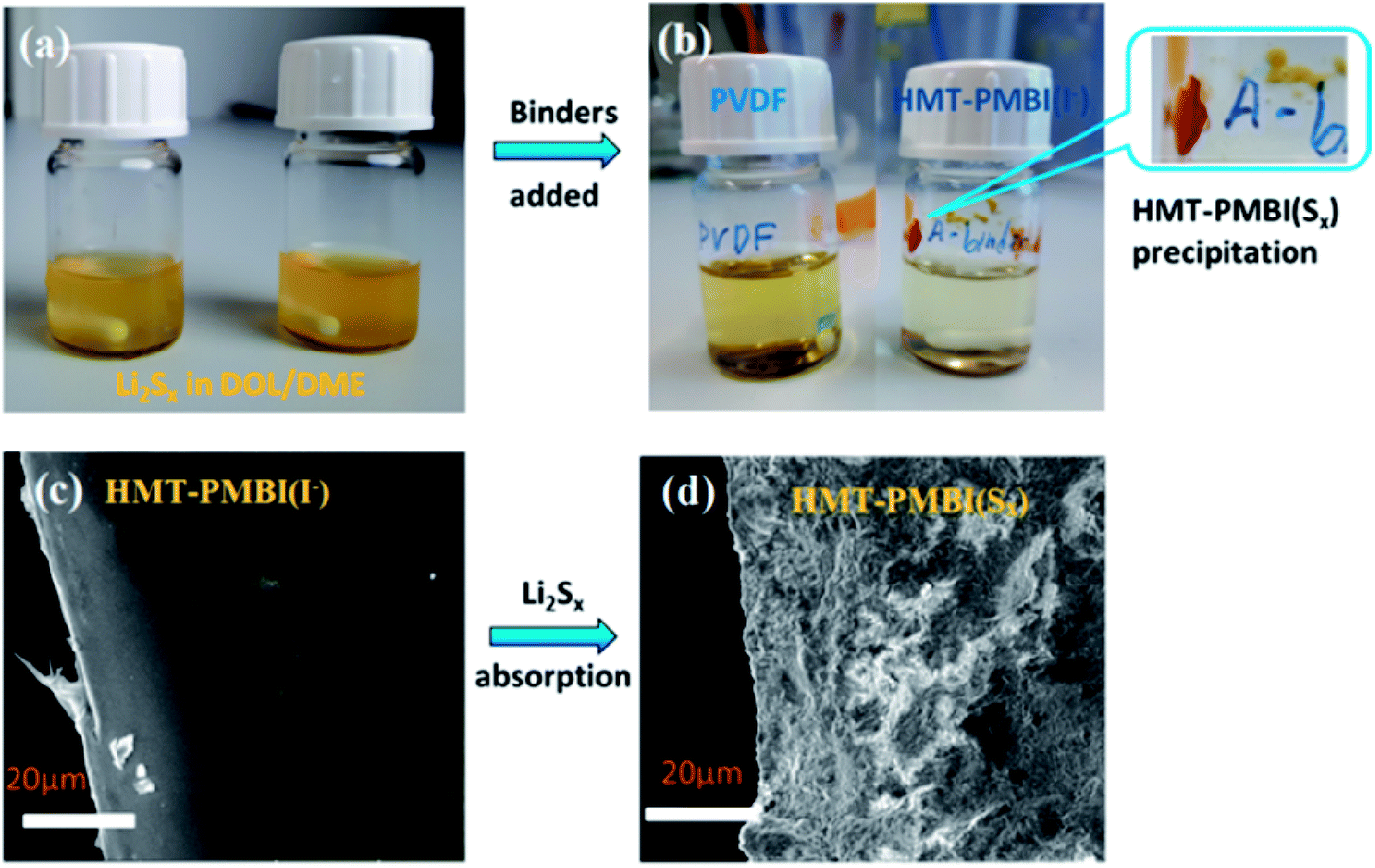 | ||
Fig. 2 Visual inspection of the interaction or lack of interaction of the PVDF and HMT-PMBI(I−) binder with Li2Sx in solution. (a) Solutions of Li2Sx in DOL/DME (1![[thin space (1/6-em)]](https://www.rsc.org/images/entities/char_2009.gif) :1), (b) respective solutions after addition of the PVDF and HMT-PMBI(I−) binders, respectively, and stirring for 10 min, and a zoomed-in image of the HMT-PMBI(Sx) precipitate in the inset. (c and d) SEM images of a pristine HMI-PMBI(I−) film and HMT-PMBI(Sx) film, respectively. :1), (b) respective solutions after addition of the PVDF and HMT-PMBI(I−) binders, respectively, and stirring for 10 min, and a zoomed-in image of the HMT-PMBI(Sx) precipitate in the inset. (c and d) SEM images of a pristine HMI-PMBI(I−) film and HMT-PMBI(Sx) film, respectively. | ||
The chemical composition of the HMT-PMBI(I−) film after absorption with Li2Sx was examined using EDX, XPS, and Raman spectroscopy to elucidate the chemical interaction between them. EDX analysis revealed the chemical composition of pristine HMT-PMBI(I−) to be 85 at% C, 10 at% N, and 5 at% I. After the Li2Sx absorption process, the I− ions of HMT-PMBI(I−) were replaced by S, resulting in the disappearance of the I peak and the appearance of the S peak (4 at%) in the EDX spectrum of HMT-PMBI(Sx) (Fig. 3a). This supports the proposed counter-ion exchange reaction (eqn (1)) occurring during the absorption process. Since EDX is used to analyze only the surface composition of samples, the extent of replacement of I− deeper in the sample is unknown.
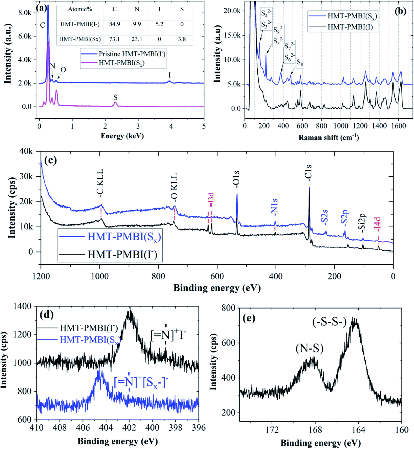 | ||
| Fig. 3 Spectra of HMI-PMBI(Sx) in comparison with those of pristine HMI-PMBI(I−): (a) EDX and (b) Raman spectra, (c) overall survey XPS spectra, (d) high resolution scan of the N area, and (e) high resolution scan of the S areas of HMI-PMBI(Sx). | ||
The absorption of Li2Sx was further confirmed by the presence of new peaks in the Raman spectrum of HMT-PMBI(Sx) corresponding to different polysulfides, S32−, S42−, S52−, S62−, S72−, and S82−,29 and the absence of such peaks in for the pristine HMT-PMBI(I−) as shown in Fig. 3b. The XPS study also confirmed the replacement of I atoms with S in HMT-PMBI(Sx), evidenced by the appearance of S(2s) and S(2p) peaks at about 203 eV and 164 eV, respectively, and the vanishing of I(3d) and I(4d) peaks in the spectrum of HMT-PMBI(Sx) as compared to that of HMT-PMBI(I−) (Fig. 3c). Furthermore, high resolution XPS spectra revealed a shift in the binding energy of the N of HMT-PMBI(Sx) to 404.5 eV relative to 402 eV for benzimidazolium (Fig. 3d).30 This was attributed to the formation of N–S bonds which increases the binding energy of the N core electrons when compared to the primary N in the benzimidazolium group of HMT-PMBI(I−). The S(2p) peak is deconvoluted into two peaks at 164 eV and 168 eV, which are ascribed to (–S–S–) of the polysulfide chain and terminal S bound to N of HMT-PMBI(S–N), respectively (Fig. 3e).31 These experimental results are consistent with density functional theory (DFT) calculations, which show that the binding energy of [SxLim]2−m (m = 0, 1) to the HMT-PMBI+ model is stronger than that of I(−) or TFSI(−) as shown in Fig. 4. More details about the most stable configurations of bonding states are available in the ESI (Fig. S1–S3†).
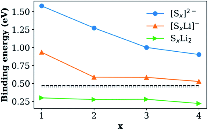 | ||
| Fig. 4 Binding energy of the HMT-PMBI+ model with [SxLim]2−m species in the presence of the DME/DOL solvent. Dashed and dotted lines show the binding energies of TFSI(−) and I(−) to the HMT-PMBI+ model, respectively. | ||
2.2 Incorporation of HMI-PMBI(I−) in Li–S coin cells
Electrochemical characterization was conducted to examine the proposed function and effect of HMT-PMBI(I−) on battery performance. During the first discharge/charge at 0.1C (1C = 1675 mA g−1), the HMT-PMBI(I−) based cell exhibited typical discharge/charge curves with an initial capacity of 1037 mA h g−1, as shown in Fig. 5a. The discharge curve at 0.1C exhibited two voltage plateaus corresponding to two opposite phase conversion reactions: one at 2.3 V for conversion from solid S8 to dissolved Li2Sx (x = 4–8) and the other at 2.1 V for conversion from dissolved Li2S4 to solid Li2S2 or Li2S.8,32 The lower voltage plateaus of the cells decreased with the C-rate much faster for the PVDF cell than for the HMT-PMBI(I−) cell (Fig. 5a, b and d). This indicates more facile Li+ transport through the HMT-PMBI(I−) binder layer than through PVDF that resulted in a lower voltage polarization of the HMT-PMBI(I−) cell compared to the PVDF cell. The cell using the HMT-PMBI(I−) binder exhibited a good discharge rate capability, indicated by a specific capacity of ∼600 mA h g−1 at 1C and ∼540 mA h g−1 at 2C, which are substantially higher than the ∼170 mA h g−1 at 1C and ∼100 mA h g−1 at 2C for the control cell (Fig. 5c). This improved discharge rate is attributed to the ionophilicity and wetting properties of the HMT-PMBI(I−) binder, resulting in faster Li+ transport within the cathode as compared to that in the cell using ionophobic/non-Li+ conducting PVDF. It is noted that due to the low wetting ability of PVDF by the electrolyte, the control cell exhibited low capacities at the first two cycles which served as activation steps (Fig. 5c).
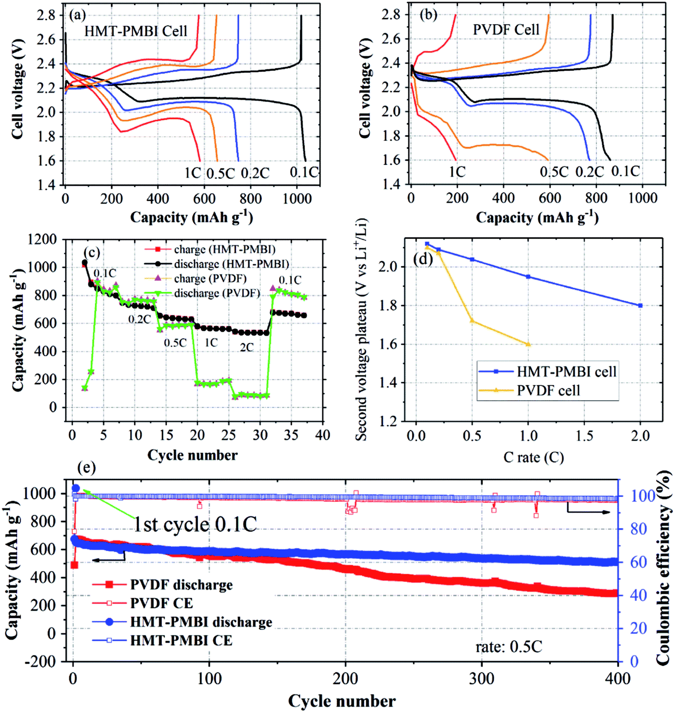 | ||
| Fig. 5 Characterization of Li–S coin cells. Discharge/charge curves of the cell with the HMT-PMBI(I−) binder (a) and with the PVDF binder (b). (c) Rate capabilities of cells using the HMT-PMBI(I−) binder in comparison to a control cell using the PVDF binder. (d) Dependence of the second voltage plateau of discharge curves on the C-rate for the two cells. (e) Charge/discharge cycling of cells with HMT-PMBI(I−) and PVDF binders after rate capability measurements. | ||
Electrochemical impedance spectroscopy (EIS) was performed to investigate the impedances of the two cells at charged states. Nyquist plots of charged HMT-PMBI(I−) cells at the pristine state, after the first cyclic voltammetry (CV) cycle, and after the first charge/discharge cycle are shown in Fig. 6a. The pristine cell exhibited a single, depressed semicircle and an inclined slope, which are assigned to charge transfer resistance (Rct) and ion transport resistance (Warburg impedance), respectively. The intersection of the EIS curve with the real axis indicates series resistance (Rs) which includes both electrical contact resistance and electrolyte resistance.33 After cyclic voltammetry and after the first charge/discharge cycle, the EIS spectra exhibited two semicircles, and the total charge transfer resistance decreased. The high frequency arc is attributed to mass transfer resistance through passivated films on both carbon and Li surfaces; the second arc represents charge transfer resistance, which is due to electrochemical reduction of polysulfides at the carbon surface. When comparing the EIS spectra of the HMT-PMBI(I−) cell with those of the PVDF cell, the HMT-PMBI(I−) cell exhibited both lower Rs and lower Rct (Fig. 6b) under the same conditions after CV measurements. The lower Rs indicates lower ohmic resistance of the HMT-PMBI(I−) cell than of the PVDF cell. The lower Rct of the HMT-PMBI(I−) cell is ascribed to a lower Li+ transfer resistance within the HMT-PMBI(I−) layer compared to PVDF.
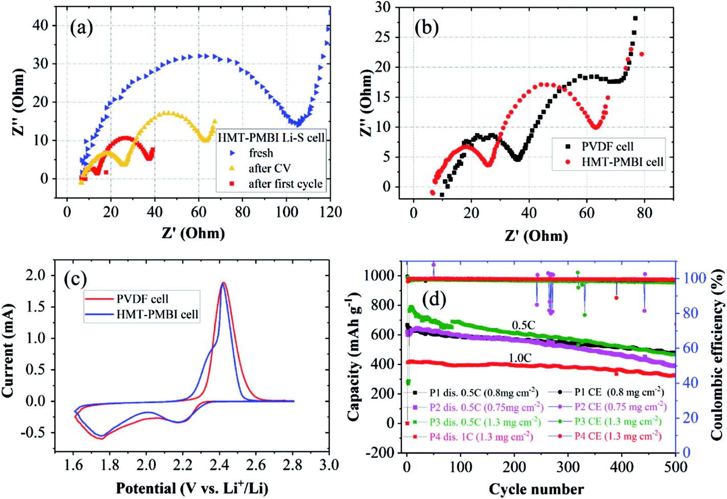 | ||
| Fig. 6 (a) EIS spectra of the HMT-PMBI(I−) cell at the pristine state, after CV, and after the first cycle. (b) EIS spectra after CV of the HMT-PMBI(I−) cell in comparison with the PVDF cell. (c) CV curves of the HMT-PMBI(I−) cell and PVDF cell. (d) Cycling performances of four cells using the HMT-PMBI(I−) binder with a S-loading range of 0.75–1.3 mg cm−2 at 0.5C (samples P1, P2, and P3) and at 1C (sample P4) for examination of the reproducibility. | ||
CV analysis revealed earlier onset potentials of both S8/S82− reduction and Sx2−/S8 oxidation peaks (Fig. 6c). These might also be attributed to the enhanced Li+ ion conductivity of the HMT-PMBI(I−) binder compared to PVDF as the other factors are the same. This is consistent with the above results from measurements of charge/discharge and rate capability experiments.
The Li+ ion conductivity of the HMT-PMBI(I−) polymer can be rationally explained as follows. First, I− anions are replaced by TFSI− from the electrolyte. This was confirmed by our DFT results from which we found a slightly better bonding of TFSI− than I(−) to HMT-PMBI (0.47 eV vs. 0.45 eV). The HMT-PMBI(TFSI−) forms a quasi-ionic liquid phase along the polymer phase and establishes a Li+ conducting phase within the polymer. Once Sx2− anions form, they will exchange with TFSI−,34 again in agreement with our calculations, c.f.Fig. 4. When Sx2− is finally reduced to S8 during the charge process, the binding energy will be 0.05 eV, lower than that of TFSI− to HMT-PMBI+ (please see Table S1, ESI†). Therefore HMT-PMBI+ will be restored upon binding to TFSI−. This process is reversible upon cycling, maintaining the active function of the HMT-PMBI binder.
Charge/discharge cycles were conducted to examine whether the ability of HMT-PMBI(I−) to trap polysulfides leads to an improved cycling stability of the cell. The cells were cycled following the rate capability experiments. After 400 cycles at 0.5C, the HMT-PMBI(I−) cell retained a capacity of 520 mA h g−1 against an initial value of 680 mA h g−1 corresponding to a degradation rate of 0.059% per cycle. This rate is 2.5 times lower than the 0.146% per cycle for the control PVDF cell which showed a capacity of 284 mA h g−1 after 400 cycles at 0.5C (Fig. 5e). The HMT-PMBI(I−) based cell exhibited a stable coulombic efficiency of ∼100% throughout the cycling time. The improved cycling performances provided by the HMT-PMBI(I−) binder were consistent in multiple cells with S loadings ranging between 0.75 and 1.3 mg cm−2, indicating the reproducibility of these results (as shown in Fig. 6d). At a higher C rate of 1C, the HMT-PMBI(I−) cell showed a further decrease in the degradation rate to a value of 0.043% per cycle after 500 cycles (Fig. 6d).
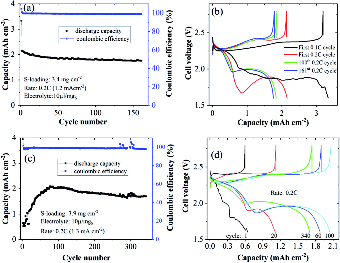 | ||
| Fig. 7 Cycling performances and discharge/charge curves of Li–S cells using N-CNTs as the S-host and the HMT-PMBI(I−) binder at S-loadings of 3.4 mgS cm−2 (a and b) and 3.9 mgS cm−2 (c and d). | ||
:DOL 1:1) but without the LiTFSI salt. HMT-PMBI(I−) remained a crystalline polymer. Therefore, we rationalize that the anion exchange process changed the HMT-PMBI polymer from the crystal form (HMT-PMBI(I−)) to an amorphous form (HMT-PMBI(TFSI−)). The amorphous form is an essential property for Li+ conduction of gel polymer electrolytes.38 XPS analyses confirmed the formation of HMT-PMBI(TFSI−) as shown in Fig. 8. The peaks of I(3d) observed in the XPS spectrum of HMT-PMBI(I−) were invisible for HMT-PMBI(TFSI−) (Fig. 8d and e) with the emergence of the S 2p peak at ∼168 eV, associated with the sulfonyl S atom of TFSI− (Fig. 8d and g).31 This indicates the occurrence of the exchange process of I− with TFSI−. The N(1s) peak of HMT-PMBI(TFSI−) can be deconvoluted into two components; one at 403 eV attributed to N(−) of TFSI−, and the other at ∼401 eV for N(+) of the benzimidazolium group. In contrast, the N(1s) peak of HMT-PMBI(I−) contains only one component at ∼401 eV for N(+) (Fig. 8f).
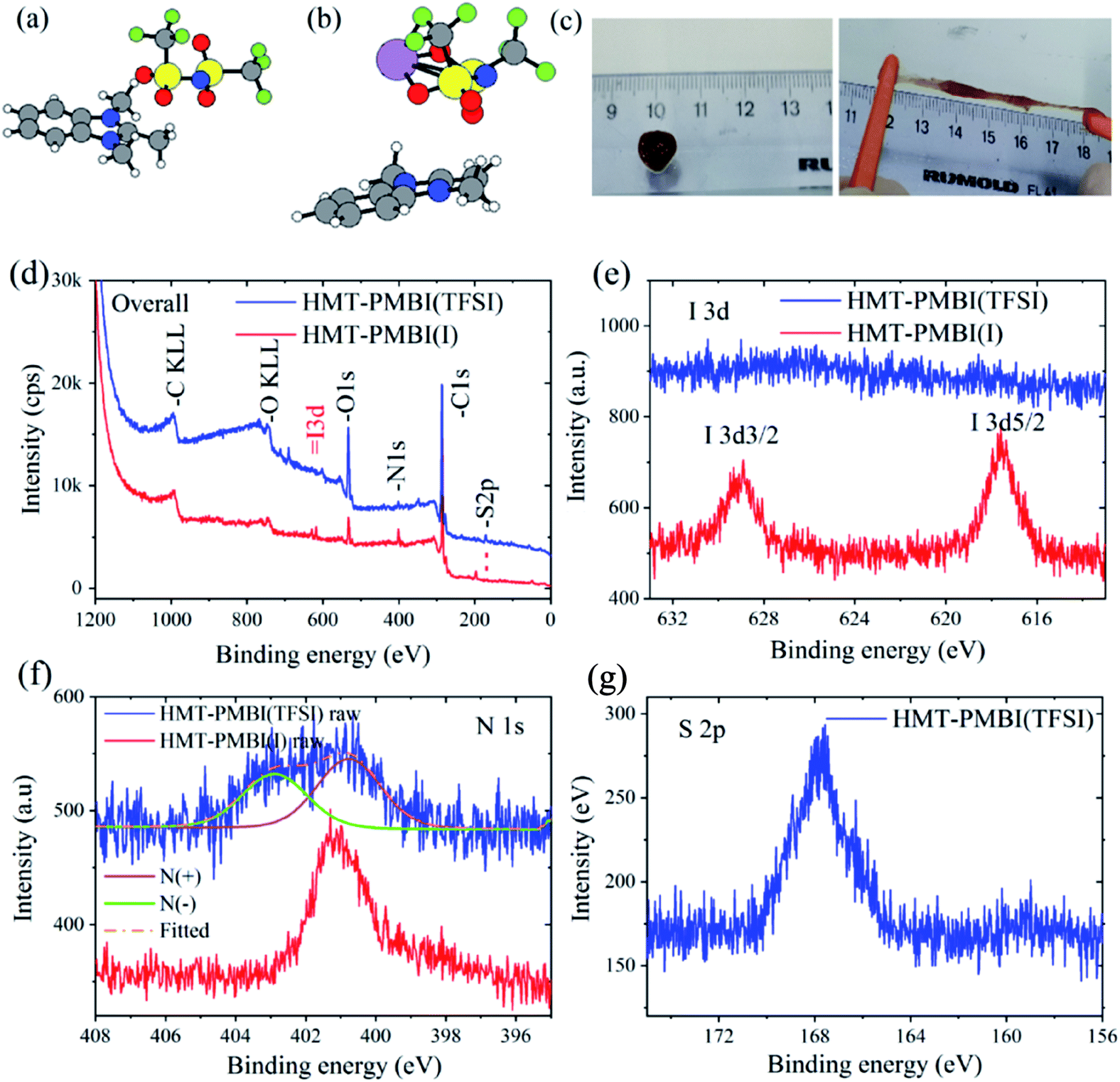 | ||
| Fig. 8 Lowest energy configurations of (a) HMT-PMBI+ bound to TFSI− and (b) HMT-PMBI+ bound to LiTFSI. C: grey, H: white, N: blue, S: yellow, O: red, F: green, and Li: purple. (c) Digital images of the HMT-PMBI(TFSI) gel (brown object on the ruler) and its stretchable properties. XPS spectra of HMI-PMBI(TFSI) in comparison with HMI-PMBI(I−): (d) overall survey spectra and (e and f) high resolution scans of the I, N, and S areas. | ||
We tested the proposed concept for Li–S batteries incorporated with the HMT-PMBI(TFSI) binder with a S loading of ∼3 mg cm−2 and a lean electrolyte/S ratio of 6 μl mgS−1. HMT-PMBI(TFSI) comprised 30 wt% LiTFSI with respect to the total mass of HMT-PMBI(I) and LiTFSI. Under the lean electrolyte conditions, the Li–S cell based on HMT-PMBI(TFSI) achieved a specific capacity of 796 mA h g−1 (2.4 mA h cm−2) at the first cycle at 0.1C (0.5 mA cm−2). With continued cycling at 0.2C, the cell required 50 conditioning cycles to be fully activated, exhibiting a stable specific capacity of 450–500 mA h g−1 (1.35–1.5 mA h cm−2) over 440 cycles (Fig. 9a). The coulombic efficiency of the cell was ∼99 ± 1%, but it suffered a fluctuation after 360 cycles, which might be due to the instability of the Li metal anode. This cell exhibited a typical discharge and charge voltage profile after cell conditioning (Fig. 9b). In contrast, while employing a lean E/S ratio, the HMT-PMBI(I) based cell delivered a low specific capacity of <300 mA h mg−1 and was dysfunctional after 120 cycles due to the shuttle effect as mentioned above (Fig. 9, S9 and S10†). The cell failure can be explained as follows. At the end of the upper voltage plateau, the concentration of dissolved Li2Sx was maximal, which severely increased the viscosity of the electrolyte under lean conditions. This led to dramatically reduced Li+ conductivity, resulting in high voltage polarization and the loss of the second voltage plateau (Fig. S9†). However, the presence of Li+ and TFSI− loosely bound in the HMT-PMBI(TFSI) matrix enhanced the electrolyte uptake and Li+ conductivity. This facilitates appropriate electrochemical conversion of S under lean electrolyte conditions. As a result, the second voltage plateau of this cell was observed (Fig. 9b).
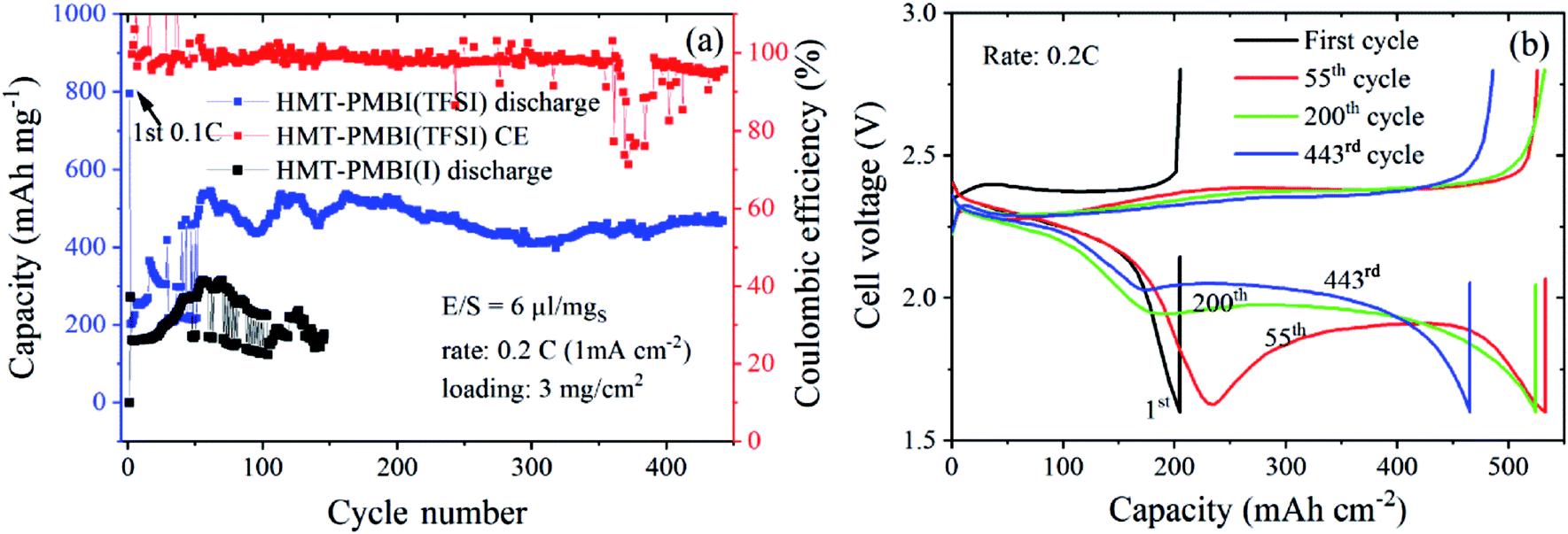 | ||
| Fig. 9 Cycling performances (a) and discharge/charge curves (b) of Li–S cells using N-CNTs as the S-host and the HMT-PMBI(TFSI) binder at a S-loading of 3 mgS cm−2 and lean E/S of 6 μl mgS−1. | ||
A gravimetric energy density of 172 kW h kg−1 was estimated for this Li–S cell using the capacity of the first cycle at 0.1C at the system level, considering the mass of the current collector, cathode, electrolyte, separator, and a simulated Li anode with a thickness of 50 μm (see Table S3† for the detailed parameters used for the energy density calculation). Although this energy density is moderate, the cycle life of the Li–S battery in this work is outstanding for Li–S batteries using 2D current collectors under lean electrolyte conditions (i.e., E/S < 7 μl mgS−1) and with a S-loading ≥3 mg cm−2 (Table S4†). The S-loadings employed in this work are lower than those achieved with the usage of 3D carbon based current collectors.39,40 However, the research community has recognized that 3D current collector cells might not be feasible for practical applications since their designs greatly differ from standard Li-ion battery configurations.24 In addition, 3D current collector configurations might require a large amount of the electrolyte, and electrode-tab welding and the high cost of carbon fiber mats are amongst other concerns. Therefore, the interesting results of Li–S cells with 2D current collectors achieved by the introduction of the novel active binder HMT-PMBI(TFSI) are promising. Still, the energy density of Li–S batteries at the cell level achieved in this work is inferior to that of the state-of-the-art Li-ion counterparts. Further optimization of cathode morphology using this binder concept in Li–S cells might even further reduce the electrolyte content and increase S loading and utilization, and could lead to practically viable Li–S batteries.
3. Conclusion
HMT-PMBI(I−) is demonstrated to serve as an active binder that also traps polysulfides within the cathodes of Li–S batteries by forming ionic interactions with dissolved polysulfide anions. This leads to a significantly improved cycling performance of the S cathode comprising sulfur, Super P carbon, and the HMT-PMBI(I−) binder as compared to the cathode using a conventional PVDF binder. The new cathode exhibited an initial capacity of 1037 mA h g−1 at 0.1C (62% S utilization) which is similar to that of the control cathode using PVDF. However, at a high discharge rate ≥1C, the HMT-PMBI(I−) cell exhibited a much higher capacity compared with the PVDF-based cell due to a higher rate capability resulting from the improved wetting of the cathode and enhanced Li+ conductivity. The HMT-PMBI(I−) binder in combination with N-doped CNTs as the S-host facilitates the fabrication and proper operation of high S-loading Li–S batteries, which have an areal capacity comparable with that of commercial Li-ion batteries. Density functional theory calculation shows that HMT-PMBI+ loosely binds with TFSI− and Li+. As a result, HMT-PMBI(I−) can exchange its I− anion with TFSI− to form HMT-PMBI(TFSI) containing loosely bound Li+. This acts as the Li+ conducting phase within the cathode, allowing a reduced electrolyte content in the Li–S cell. Therefore, the new active binder enables a stable cyclability of >440 cycles for Li–S batteries with a relatively high S-loading (3–4 mg cm−2) and a lean electrolyte content of 6 μl mgS−1. Although the specific energy density of this Li–S cell is moderate, to our knowledge this is one of the few most outstanding cyclabilities reported to date for Li–S batteries under lean electrolyte conditions and relatively high loadings. We suggest that integration of this new binder with other advanced components, e.g. electrolyte, anode, and host materials, could result in further improved performance of Li–S batteries. As this work uses all inexpensive, commercially available materials and conventional battery fabrication, the results are highly relevant to practical applications. HMT-PMBI(I−) can also be applicable as a new binder for other battery types such as Li-ion batteries.4. Methods
4.1 Electrochemical characterization
The sulfur/carbon composite was prepared by first grinding carbon (Super P) and S powder in a vial using a stir bar for 12 h. The obtained S/C composite (70 wt% S) was further annealed at 155 °C in a sealed vial. The final S content was 68 wt% which was calculated from the weight of the final composite. The cathode slurry was fabricated by stirring a mixture of 80 wt% S/C composite, 10 wt% Super P carbon, and 10 wt% HMT-PMBI(I−) binder (Ionomr Innovations Inc) in N-methy1-2-pyrrolidone in a vial on a magnetic stir plate at room temperature overnight. S cathodes were prepared by coating the slurry on a carbon-coated aluminum foil current collector using the doctor-blade coating technique, followed by drying in a vacuum oven at 60 °C for 12 h. For coin cell assembly, the sulfur electrodes were cut into discs with a diameter of 11.1 mm, corresponding to the geometric disc area of 0.97 cm2. The sulfur loading was about 1.0 mg cm−2 for carbon black based electrodes. The electrolyte was a solution of 1.0 M lithium bis-trifluoromethane sulfonylimide (LiTFSI) and 0.2 M LiNO3 additive in a mixed solvent of 1,3-dioxolane (DOL) and 1,2-dimethoxyethane (DME) with a volume ratio of 1:1. An electrolyte dose corresponding to 15 μl mgS−1 was used for the basic cell tests. Li chips with a diameter of 15.6 mm and a thickness of 0.45 mm were used as the counter electrodes. Coin cells (CR2032) were assembled in an Ar-filled glove box with Celgard PP separators (25 μm thick). The rate capability and cycling performance were analyzed using a Landt CT2001A-5V 5 mA battery tester between 1.6 and 2.8 V at various current densities. High loading S/NCNT based coin cells were prepared and tested in the same manner as described above except for the following. The S content in the S/NCNT composite was 75 wt%, the electrolyte content was 10 μl mgS−1, an ink mixture of 75 wt% S/NCNT composite, 15 wt% Super P carbon, and 10 wt% HMT-PMBI(I−) binder was used, and the S loadings were 2–4 mg cm−2. NCNTs were purchased from ACS Materials with detailed parameters available in the ESI.† For the lean electrolyte tests, HMT-PMBI(TFSI) Li–S coin cells with a lean electrolyte were fabricated using the same procedure as that for the HMT-PMBI(I−) based cells except that during the first step of slurry preparation, the I− anion of HMT-PMBI(I) was exchanged with TFSI−. In particular, HMT-PMBI(I−) and LiTFSI with a 7:3 wt ratio were added to the NMP solution and continuously stirred for 2 h before S/NCNTs and Super P carbon were added. The same electrolyte was used but with a dosage corresponding to 6 μl mgS−1. CV tests were performed at a scan rate of 0.1 mV s−1 in a potential window of 1.6–2.8 V (vs. Li/Li+) and EIS measurements were conducted in the frequency range from 0.1 to 105 Hz at a constant perturbation amplitude of 5 mV on an ECi-200 potentiostat (Nordic Electrochemistry).
4.2 Simulation
Density functional theory (DFT) calculations were performed with the GPAW package,41,42 where the electron density and the Kohn–Sham wave functions are represented using the PAW formalism.43 The smooth wave functions were represented on real space grids with a grid spacing of 0.2 Å. Exchange and correlation energies were approximated as devised by Perdew, Burke and Ernzerhof (PBE).44 Solvent effects are considered by using the average value of ε = 7.27 for DME and DOL.45The HMT-PMBI polymer was modeled using the 1,2,3-trimethyl 1H-benzimidazolium cation as shown in Fig. 8a. Bonded structures were created by placing the molecules in random relative orientations resulting in at least 150 configurations for each pairing. These were allowed to relax without symmetry restrictions until all forces were found to be below 0.05 eV Å−1. The energetically lowest structure was used to obtain the binding energy.
Conflicts of interest
Polybenzimidazolium AEM technology is licensed by Simon Fraser University to Ionomr Innovations Inc. Steven Holdcroft and Benjamin Britton are co-founders and minor shareholders of Ionomr Innovations Inc. The authors declare no conflicting interests.Acknowledgements
This work was financed by the Deutsche Forschungsgemeinschaft (DFG) under project number 389154849. We thank Thomas Böhm for Raman spectra measurements.References
- H.-G. Jung, M. W. Jang, J. Hassoun, Y.-K. Sun and B. Scrosati, Nat. Commun., 2011, 2, 516 CrossRef.
- M. Armand and J.-M. Tarascon, Nature, 2008, 451(7179), 652 CrossRef CAS.
- P. G. Bruce, S. A. Freunberger, L. J. Hardwick and J.-M. Tarascon, Nat. Mater., 2012, 11(1), 19 CrossRef CAS.
- Y. Yang, G. Zheng and Y. Cui, Chem. Soc. Rev., 2013, 42(7), 3018 RSC.
- X. Fang and H. Peng, Small, 2015, 11(13), 1488 CrossRef CAS PubMed.
- S. Waluś, C. Barchasz, J.-F. Colin, J.-F. Martin, E. Elkaïm, J.-C. Leprêtre and F. Alloin, Chem. Commun., 2013, 49(72), 7899 RSC.
- A. Manthiram, Y. Fu, S.-H. Chung, C. Zu and Y.-S. Su, Chem. Rev., 2014, 114(23), 11751 CrossRef CAS PubMed.
- X. Ji, K. T. Lee and L. F. Nazar, Nat. Mater., 2009, 8(6), 500 CrossRef CAS.
- L. Ji, M. Rao, H. Zheng, L. Zhang, Y. Li, W. Duan, J. Guo, E. J. Cairns and Y. Zhang, J. Am. Ceram. Soc., 2011, 133(46), 18522 CAS.
- G. He, X. Ji and L. Nazar, Energy Environ. Sci., 2011, 4(8), 2878 RSC.
- X. Ji, S. Evers, R. Black and L. F. Nazar, Nat. Commun., 2011, 2, 325 CrossRef PubMed.
- N. Jayaprakash, J. Shen, S. S. Moganty, A. Corona and L. A. Archer, Angew. Chem., Int. Ed., 2011, 50(26), 5904 CrossRef CAS PubMed.
- S. Xin, L. Gu, N.-H. Zhao, Y.-X. Yin, L.-J. Zhou, Y.-G. Guo and L.-J. Wan, J. Am. Ceram. Soc., 2012, 134(45), 18510 CAS.
- H.-J. Peng, J. Liang, L. Zhu, J.-Q. Huang, X.-B. Cheng, X. Guo, W. Ding, W. Zhu and Q. Zhang, ACS Nano, 2014, 8(11), 11280 CrossRef CAS.
- G. Li, W. Lei, D. Luo, Y.-P. Deng, D. Wang and Z. Chen, Adv. Energy Mater., 2017, 498, 1702381 Search PubMed.
- M. Liu, Q. Meng, Z. Yang, X. Zhao and T. Liu, Chem. Commun., 2018, 54, 5090 RSC.
- S.-H. Chung, C.-H. Chang and A. Manthiram, Adv. Funct. Mater., 2018, 114, 1801188 CrossRef.
- X. Yang, X. Li, K. Adair, H. Zhang and X. Sun, Electrochem. Energy Rev., 2018, 2(44), 76 Search PubMed.
- M. Hagen, D. Hanselmann, K. Ahlbrecht, R. Maça, D. Gerber and J. Tübke, Adv. Energy Mater., 2015, 5(16), 1401986 CrossRef.
- H. Pan, K. S. Han, M. H. Engelhard, R. Cao, J. Chen, J.-G. Zhang, K. T. Mueller, Y. Shao and J. Liu, Adv. Funct. Mater., 2018, 8, 1707234 CrossRef.
- R. Fang, S. Zhao, Z. Sun, D.-W. Wang, H.-M. Cheng and F. Li, Adv. Mater., 2017, 29, 1606823 CrossRef PubMed.
- Y. Yang, Y. Zhong, Q. Shi, Z. Wang, K. Sun and H. Wang, Angew. Chem., 2018, 57(47), 15549 CrossRef CAS PubMed.
- W. Xue, Z. Shi, L. Suo, C. Wang, Z. Wang, H. Wang, K. P. So, A. Maurano, D. Yu, Y. Chen, L. Qie, Z. Zhu, G. Xu, J. Kong and J. Li, Nat. Energy, 2019, 29, 1601759 Search PubMed.
- M. Li, Y. Zhang, Z. Bai, W. W. Liu, T. Liu, J. Gim, G. Jiang, Y. Yuan, D. Luo, K. Feng, R. S. Yassar, X. Wang, Z. Chen and J. Lu, Adv. Mater., 2018, 30(46), e1804271 CrossRef.
- A. G. Wright, J. Fan, B. Britton, T. Weissbach, H.-F. Lee, E. A. Kitching, T. J. Peckham and S. Holdcroft, Energy Environ. Sci., 2016, 9(6), 2130 RSC.
- J. Liu, Q. Zhang and Y.-K. Sun, J. Power Sources, 2018, 396, 19 CrossRef CAS.
- Y. Zhao, M. Hong, N. Bonnet Mercier, G. Yu, H. C. Choi and H. R. Byon, Nano Lett., 2014, 14(2), 1085 CrossRef CAS PubMed.
- F. Wu, J. T. Lee, N. Nitta, H. Kim, O. Borodin and G. Yushin, Adv. Mater., 2015, 27(1), 101 CrossRef CAS.
- M. Hagen, P. Schiffels, M. Hammer, S. Dorfler, J. Tubke, M. J. Hoffmann, H. Althues and S. Kaskel, J. Electrochem. Soc., 2013, 160(8), A1205–A1214 CrossRef CAS.
- C.-Y. Chen, H.-J. Peng, T.-Z. Hou, P.-Y. Zhai, B.-Q. Li, C. Tang, W. Zhu, J.-Q. Huang and Q. Zhang, Adv. Mater., 2017, 29, 1606802 CrossRef.
- https://srdata.nist.gov/xps/Default.aspx, last accessed June 2018.
- S. S. Zhang, Electrochim. Acta, 2012, 70, 344 CrossRef CAS.
- N. A. Cañas, K. Hirose, B. Pascucci, N. Wagner, K. A. Friedrich and R. Hiesgen, Electrochim. Acta, 2013, 97, 42 CrossRef.
- L. Li, T. A. Pascal, J. G. Connell, F. Y. Fan, S. M. Meckler, L. Ma, Y.-M. Chiang, D. Prendergast and B. A. Helms, Nat. Commun., 2017, 8(1), 2277 CrossRef.
- H.-J. Peng, T.-Z. Hou, Q. Zhang, J.-Q. Huang, X.-B. Cheng, M.-Q. Guo, Z. Yuan, L.-Y. He and F. Wei, Adv. Mater. Interfaces, 2014, 1(7), 1400227 CrossRef.
- J. Xiao, Adv. Energy Mater., 2015, 5(16), 1501102 CrossRef.
- D. Lv, J. Zheng, Q. Li, X. Xie, S. Ferrara, Z. Nie, L. B. Mehdi, N. D. Browning, J.-G. Zhang, G. L. Graff, J. Liu and J. Xiao, Adv. Energy Mater., 2015, 5(16), 1402290 CrossRef.
- D. Lei, K. Shi, H. Ye, Z. Wan, Y. Wang, L. Shen, B. Li, Q.-H. Yang, F. Kang and Y.-b. He, Adv. Funct. Mater., 2018, 28(38), 1707570 CrossRef.
- S.-H. Chung and A. Manthiram, Adv. Mater., 2018, 30, 1705951 CrossRef.
- S.-H. Chung and A. Manthiram, Joule, 2018, 2, 1–15 CrossRef.
- J. J. Mortensen, L. B. Hansen and K. W. Jacobsen, Phys. Rev. B: Condens. Matter Mater. Phys., 2005, 71(3), 4351 CrossRef.
- J. Enkovaara, C. Rostgaard, J. J. Mortensen, J. Chen, M. Dułak, L. Ferrighi, J. Gavnholt, C. Glinsvad, V. Haikola, H. A. Hansen, H. H. Kristoffersen, M. Kuisma, A. H. Larsen, L. Lehtovaara, M. Ljungberg, O. Lopez-Acevedo, P. G. Moses, J. Ojanen, T. Olsen, V. Petzold, N. A. Romero, J. Stausholm-Møller, M. Strange, G. A. Tritsaris, M. Vanin, M. Walter, B. Hammer, H. Häkkinen, G. K. H. Madsen, R. M. Nieminen, J. K. Nørskov, M. Puska, T. T. Rantala, J. Schiøtz, K. S. Thygesen and K. W. Jacobsen, J. Phys.: Condens. Matter, 2010, 22(25), 253202 CrossRef CAS.
- P. E. Blochl, Phys. Rev. B: Condens. Matter Mater. Phys., 1994, 50(24), 17953 CrossRef.
- J. P. Perdew, K. Burke and M. Ernzerhof, Phys. Rev. Lett., 1996, 77(18), 3865 CrossRef CAS PubMed.
- A. Held and M. Walter, J. Chem. Phys., 2014, 141(17), 174108 CrossRef PubMed.
Footnote |
| † Electronic supplementary information (ESI) available. See DOI: 10.1039/c9se01092k |
| This journal is © The Royal Society of Chemistry 2020 |