
Selective hydrogenation of furfural to tetrahydrofurfuryl alcohol over a Rh-loaded carbon catalyst in aqueous solution under mild conditions†
Babasaheb M.
Matsagar‡
 *a,
Chang-Yen
Hsu‡
a,
Season S.
Chen
b,
Tansir
Ahamad
c,
Saad M.
Alshehri
c,
Daniel C. W.
Tsang
*b and
Kevin C.-W.
Wu
*ade
*a,
Chang-Yen
Hsu‡
a,
Season S.
Chen
b,
Tansir
Ahamad
c,
Saad M.
Alshehri
c,
Daniel C. W.
Tsang
*b and
Kevin C.-W.
Wu
*ade
aDepartment of Chemical Engineering, National Taiwan University, No. 1, Sec. 4, Roosevelt Road, Taipei 10617, Taiwan. E-mail: matsagar03@ntu.edu.tw; kevinwu@ntu.edu.tw
bDepartment of Civil and Environmental Engineering, The Hong Kong Polytechnic University, Huan Hom, Kowloon, Hong Kong, China. E-mail: dan.tsang@polyu.edu.hk
cDepartment of Chemistry, College of Science, King Saud University, P. O. Box 2455, Riyadh 11451, Saudi Arabia
dCenter of Atomic Initiative for New Materials (AI-MAT), National Taiwan University, Taiwan
eInternational Graduate Program of Molecular Science and Technology, National Taiwan University (NTU-MST), Taiwan
First published on 4th November 2019
Abstract
We describe the selective hydrogenation of furfural (FAL) into tetrahydrofurfuryl alcohol (THFA) under mild conditions (30 °C) in aqueous media using an Rh-loaded carbon (Rh/C) catalyst in a one-pot fashion. In FAL hydrogenation, the Rh/C catalyst showed a high THFA yield (92%) with 93% selectivity in aqueous media within 12 h, whereas the use of a dimethylacetamide (DMA) solvent system resulted in a 95% THFA yield within 32 h at 30 °C. The study of the effect of the solvent on FAL hydrogenation reveals that polar solvents showed higher THFA yields than a toluene solvent. The Rh/C catalyst used in this study exhibited higher activity compared to Ru/C, Pd/C, Ni/C derived from Ni-based metal–organic framework (Ni-MOF), and Ni-loaded carbon black (Ni/CB) catalysts in FAL-to-THFA hydrogenation. The Rh/C catalyst is characterized in detail using various characterization techniques such as TEM, XRD, N2-adsorption–desorption, XPS, and ICP-OES to understand its physicochemical properties. The Rh/C catalyst shows similar high THFA yields in the recycling experiment of FAL hydrogenation under ambient conditions.
Introduction
Furfural (FAL) is a platform chemical mainly obtained from hydrolysis of hemicellulose followed by a dehydration reaction.1–5 It is one of the most promising sustainable starting chemicals used for the synthesis of various vital chemicals; for example, hydrogenation of FAL produces furfuryl alcohol (FOL), tetrahydrofurfuryl alcohol (THFA), 2-methylfuran (2-MF), 2-methyltetrahydrofuran (2-MTHF), tetrahydrofuran (THF), 1,5-pentanediol (1,5-PD), etc.6–14 Further oxidation of FAL produces furoic acid and maleic acid.15–17 Although FAL can be converted into a variety of useful chemicals, its selective hydrogenation into the desired product is difficult. The selective hydrogenation of FAL is imperative since this method will offer a higher yield of the desired product and also avoid the difficulty in the separation and purification of the desired products. Therefore, many research studies are dedicated to the selective hydrogenation of furfural to THFA or 2-MTHF.18 THFA is one of the important hydrogenation products of FAL and is considered an environment-friendly solvent because of its biodegradability, low toxicity, and stable properties.19,20 Furthermore, THFA is broadly used in the automotive industry as a stripping solvent to remove protective coatings, paint, and epoxy coatings. It is also widely used as an intermediate and green solvent in industrial and agricultural applications.1,21,22 Furthermore, it can be selectively hydrogenated into not only economically valuable furan chemicals such as 2-MTHF and THF but also products like 1,2-pentanediol (1,2-PD) and 1,5-PD.7,8,23–28The synthesis of THFA can be carried out by complete hydrogenation of C![[double bond, length as m-dash]](https://www.rsc.org/images/entities/char_e001.gif) O and CC double bonds of FAL.29,30 In this case, FAL is typically first hydrogenated to FOL, and then FOL is further hydrogenated into THFA.31,32 FOL hydrogenation to THFA is a difficult step since it requires a higher hydrogen pressure and reaction temperature.22,33,34 Gowda et al. reported FOL hydrogenation to THFA with 99% selectivity using ruthenium(II) bis(diimine) complexes under 5 MPa H2 pressure and 130 °C reaction temperature.35 A 5% Ru/TiO2 catalyst is reported for the hydrogenation of FOL under 4 MPa hydrogen pressure (40–90 °C), and the result shows >97% THFA selectivity at 60 °C.21 Recently, Wang et al. reported the use of bimetallic MOF-derived Ni–Co alloy nanoparticles (particle size < 1 nm) as a catalyst for the hydrogenation of FOL into THFA. The result indicates 99.8% FOL conversion with 99.1% THFA selectivity within 8 h under 3 MPa hydrogen pressure and 80 °C reaction temperature.33 Furthermore, Farooq-Ahmad et al. reported highly selective and low-temperature hydrogenation of FOL to THFA using ruthenium nanoparticles (∼4 nm) intercalated in hectorite under 2 MPa hydrogen pressure; however, the ruthenium nanoparticles are deactivated under these reaction conditions.36 These reports describe the use of a FOL substrate and higher hydrogen pressure to achieve a superior THFA yield. However, to improve the economic viability, it is suggested to use a FAL substrate and perform hydrogenation reactions under ambient conditions.
O and CC double bonds of FAL.29,30 In this case, FAL is typically first hydrogenated to FOL, and then FOL is further hydrogenated into THFA.31,32 FOL hydrogenation to THFA is a difficult step since it requires a higher hydrogen pressure and reaction temperature.22,33,34 Gowda et al. reported FOL hydrogenation to THFA with 99% selectivity using ruthenium(II) bis(diimine) complexes under 5 MPa H2 pressure and 130 °C reaction temperature.35 A 5% Ru/TiO2 catalyst is reported for the hydrogenation of FOL under 4 MPa hydrogen pressure (40–90 °C), and the result shows >97% THFA selectivity at 60 °C.21 Recently, Wang et al. reported the use of bimetallic MOF-derived Ni–Co alloy nanoparticles (particle size < 1 nm) as a catalyst for the hydrogenation of FOL into THFA. The result indicates 99.8% FOL conversion with 99.1% THFA selectivity within 8 h under 3 MPa hydrogen pressure and 80 °C reaction temperature.33 Furthermore, Farooq-Ahmad et al. reported highly selective and low-temperature hydrogenation of FOL to THFA using ruthenium nanoparticles (∼4 nm) intercalated in hectorite under 2 MPa hydrogen pressure; however, the ruthenium nanoparticles are deactivated under these reaction conditions.36 These reports describe the use of a FOL substrate and higher hydrogen pressure to achieve a superior THFA yield. However, to improve the economic viability, it is suggested to use a FAL substrate and perform hydrogenation reactions under ambient conditions.
In addition, researchers have reported the one-step hydrogenation reaction of FAL to THFA; for example, Nakagawa et al. reported the hydrogenation of FAL to THFA with high selectivity (94%) in aqueous media using a Pd–Ir/SiO2 bimetallic catalyst at low temperature (4 °C) and high hydrogen pressure (8 MPa).37 Similarly, Yanliang et al. demonstrated the use of a Ni/Ba–Al2O3 catalyst for the hydrogenation of FAL to THFA, and the results indicated that a high hydrogen pressure (4 MPa) and a low reaction temperature help to decrease side reactions.34 Furthermore, Liu et al. reported the use of bimetallic Cu–Ni supported on multiwalled carbon nanotubes and Ni supported on carbon nanotubes as catalysts for the selective hydrogenation of FAL to THFA.38 The bimetallic Cu–Ni/CNT catalyst showed superior activity with 90% THFA selectivity and 100% FAL conversion. However, in this reaction a higher H2 pressure (4 MPa) and reaction temperature (130 °C) were used.
Although many reports show complete conversion of FAL/FOL with 100% selectivity of THFA using various catalysts such as a hydroxyapatite-supported Pd catalyst (H2 pressure 1 MPa, 120 °C),39 a Ni-MOF derived Ni/C nanocatalyst (1 MPa, 120 °C),40 Ni/γ-Al2O3 (H2 pressure 4 MPa, 80 °C),25 and Ni–Co/SBA-15 (H2 pressure 5 MPa, 90 °C, THFA selectivity 92%),41 the FAL hydrogenation to THFA was performed under high H2 pressure and temperature. Furthermore, in many reactions, the FOL substrate was used instead of FAL. To overcome this issue, in the present work, we employed the Rh/C catalyst for the effective hydrogenation of FAL selectively to THFA in a one-pot method at an ambient reaction temperature (Scheme 1). The reaction conditions were optimized for the Rh/C catalyst to achieve the highest THFA yield from FAL at an ambient reaction temperature. Furthermore, catalyst characterization was carried out in detail using various characterization techniques. The catalytic activity of the Rh/C catalyst was compared with that of various other supported metal catalysts (Ru/C, Pd/C, Ni/carbon black (Ni/CB), and Ni/C derived from Ni-MOF) for the hydrogenation of FAL and FOL into THFA.
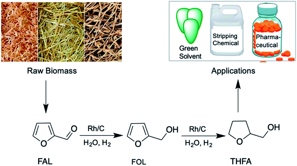 | ||
| Scheme 1 Selective hydrogenation of FAL to THFA using a Rh/C catalyst in aqueous media. | ||
Experimental
Materials and methods
Furfural (FAL, purity 99%) and 2-methylfuran (2-MF, purity 99%) were supplied by Acros Organics. Nickel(II) nitrate hexahydrate (Ni(NO3)2·6H2O, purity 99.9%), 2-methyltetrahydrofuran (2-MTHF, purity 99%), furfuryl alcohol (FOL, purity 98%), Ru/C (5 wt%), and Pd/C (5 wt%) were purchased from Sigma-Aldrich. Tetrahydrofurfuryl alcohol (THFA, purity 98%), 1,2-pentanediol (1,2-PD, purity >98%), 1,5-pentanediol (1,5-PD, purity 97%) and N,N-dimethylacetamide (DMA, purity 99.5%) were purchased from Tokyo Chemical Industry (TCI). The Rh/C (5 wt%) catalyst was procured from Alfa Aesar while the Ni/CB and Ni/C-derived from Ni-MOF catalysts were prepared in the lab using known reported methods (Schemes 1 and 2; ESI†).40,42The hydrogenation reactions under ambient pressure were carried out in 50 mL round bottom (RB) flasks while the reactions at higher pressure were carried out in a Parr autoclave (closed system). For a typical FAL hydrogenation reaction, first FAL was added in the RB flask/Parr autoclave followed by the catalyst and solvent. The reactions were carried out for the desired time and at the desired temperature under continuous stirring. During the reaction, for the open reaction system, pure hydrogen gas was passed into the reaction mixture with a flow rate of 30 mL min−1, and in the case of the closed reaction system, reactions were performed under the desired hydrogen pressure.
Product analysis and calculations
The analysis of the aqueous reaction mixture was performed using High-Performance Liquid Chromatography (HPLC) while the analysis of the organic reaction mixture was carried out using Gas Chromatography (GC). After completion of the reaction, the samples were centrifuged to separate the solid residue. The recovered liquid phase is then passed through a 0.22 μm syringe filter to remove the remaining solid residue. After separating the solid residue, the liquid samples were analyzed using a GC equipped with a Quadrex column (077-FFAAP) and Flame Ionization Detector (FID) and a HPLC equipped with a Pb2+ column and refractive index (RI) detector. Millipore water was used as the mobile phase for HPLC with a 1 mL min−1 flow rate, and the column oven temperature was set at 80 °C during the analysis.| Yield of THFA (%) = moles of THFA (HPLC or GC)/theoretical moles of THFA based on conversion × 100 |
| Yield of FOL (%) = moles of FOL (HPLC or GC)/theoretical moles of FOL based on conversion × 100 |
| Conversion of FAL (%) = initial moles of FAL − moles of FAL after initial reaction/moles of FAL × 100 |
Results and discussion
Catalyst characterization
The Rh/C catalyst was characterized using transmission electron microscopy with energy-dispersive spectroscopy (TEM/EDS), transmission electron microscopy (TEM), X-ray diffraction (XRD), N2-adsorption–desorption analysis, X-ray photoelectron spectroscopy (XPS), and inductively coupled plasma atomic emission spectroscopy (ICP-OES). The Ni/C derived from Ni-MOF and Ni/CB catalysts were prepared in the lab and characterized using XRD and SEM analysis; the details are provided in the ESI (Fig. S4–S7†).The distribution of Rh metal nanoparticles on the carbon support and the size of the Rh nanoparticles were measured with TEM and TEM/EDS (Fig. 1(a) and S2†). The TEM image shown in Fig. 1(a) revealed that Rh nanoparticles were evenly distributed over the carbon support, with a uniform particle size ranging from 3–6 nm. The average Rh nanoparticle size of the Rh/C catalyst was 4.8 nm estimated by TEM analysis of randomly selected Rh particles (Fig. 1(a)). The TEM/EDS elemental mapping (Fig. S2†) confirmed the presence of various elements such as carbon (C, 81.2 wt%), oxygen (O, 11.3 wt%), silicon (Si, 0.63 wt%), sulfur (S, 0.66 wt%) and rhodium (Rh, 5.9 wt%) in the Rh/C catalyst.43 Besides, the ICP-OES analysis of Rh/C catalyst indicated 5.2 wt% Rh in the Rh/C catalyst. These results indicate that the Rh nanoparticles were indeed evenly distributed on the carbon support. The XRD pattern of the Rh/C catalyst exhibits a broad peak at 2θ = 22.8 degrees, which can be attributed to the amorphous carbon structures or tiny crystallites. As seen in Fig. S1,† the diffraction peak at 26.3 degrees corresponds to graphitic carbon,44 and the diffraction peak at 2θ = 43 degrees indicates the (101) plane of carbon which might merge with the additional broad diffraction peak at 2θ = 41 degrees indexed to the Rh (111) plane (JCPDS file no. 65-2866).45 The other diffraction peaks ascribed to Rh are shown using blue lines in Fig. S1;† however, because of the smaller particle size (4.8 nm), the peaks for Rh are not seen in the XRD pattern.43,45
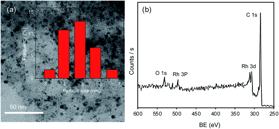 | ||
| Fig. 1 (a) TEM image and particle size distribution of Rh in the Rh/C catalyst and (b) wide scan XPS spectrum of the Rh/C catalyst. | ||
The porosity and surface area of the Rh/C catalyst were examined using N2 adsorption–desorption measurements performed at −196 °C using a BELSORP-II max instrument. Before N2 adsorption–desorption measurement, the sample was degassed under vacuum (1 × 10⁻³ MPa) at 150 °C for 8 h. The Rh/C characterized using N2 adsorption–desorption measurements exhibits a type II adsorption isotherm (IUPAC classification). The adsorption isotherm is not regarded as type IV because of the absence of a plateau at high p/po. The specific surface area (SBET) calculated using the Brunauer–Emmett–Teller (BET) method is 583 ± 10 m2 g−1, and the average pore diameter is 3 nm based on the adsorption isotherm. The pore volume distribution for the support of the Rh/C catalyst was determined using the Non-Localized Density Functional Theory (NLDFT) method (pore volume Vp = 0.39 cm3 g−1). The degree of metal dispersion measured using H2 chemisorption was 52.8%.
Furthermore, as shown in Fig. 1(b) and S3(a) and (b),† the Rh/C catalyst was examined using XPS to understand the chemical status of Rh in the Rh/C catalyst. The wide scan XPS spectrum exhibits the signals for Rh 3d, Rh 3p, C 1s, and O 1s (Fig. 1(b)). Peak shape analysis was carried out by applying the Shirley type background correction method, followed by curve fitting with Gaussian–Lorentzian functions.46 The high-resolution Rh 3d XPS spectrum shows peaks for Rh 3d5/2 and Rh 3d3/2 at binding energies (BEs) of 307.6 eV and 312.3 eV corresponding to the metallic state of Rh while the peaks at BEs of 308.6 eV (Rh 3d5/2) and 313.6 (Rh 3d3/2) correspond to the oxidized state of Rh.45,47,48 More details about XPS characterization are available in our previous work.43 As shown in Fig. S3(b),† the C 1s XPS spectrum splits into three peaks at 289 eV, 286.2 eV and 284.8 eV which are indexed to O–CO, C–O–C, and C–C, respectively.
Catalyst evaluation study and the effect of reaction time in aqueous media
To study the catalytic performance of the Rh/C catalyst for FAL hydrogenation into THFA, reactions were carried out with various supported metal catalysts including Ni/CB, Ni/C, Ru/C, Pd/C, and Rh/C. As shown in Fig. 2(a), FAL hydrogenation reactions were carried out in water at 30 °C using 1 MPa H2 pressure by a one-pot method. The reactions performed with the Ni/C catalyst derived from Ni-MOF and the Ru/C and Pd/C catalysts result in 20%, 10%, and 72% THFA yield, respectively, while the Ni/CB catalyst fails to catalyze the hydrogenation of FAL under similar reaction conditions. Without a catalyst, furfural is stable under the reaction conditions and is not converted into any of its hydrogenation products. Furthermore, the Rh/C catalyst exhibited the highest THFA yield (82%) and selectivity (90%) under similar reaction conditions. The supported metal catalysts such as Ru/C and Pd/C showed the formation of an over-hydrogenated product (2-MTHF) which results in lower THFA selectivity. These results suggest that the Rh/C catalyst showed higher selectivity for THFA compared to all the other catalysts used in this study. Rode et al. reported that the Rh/C catalyst for the ring hydrogenation of aromatics such as ring hydrogenation of phenol shows higher activity compared to Pt/C, Pd/C and Ru/C catalysts.49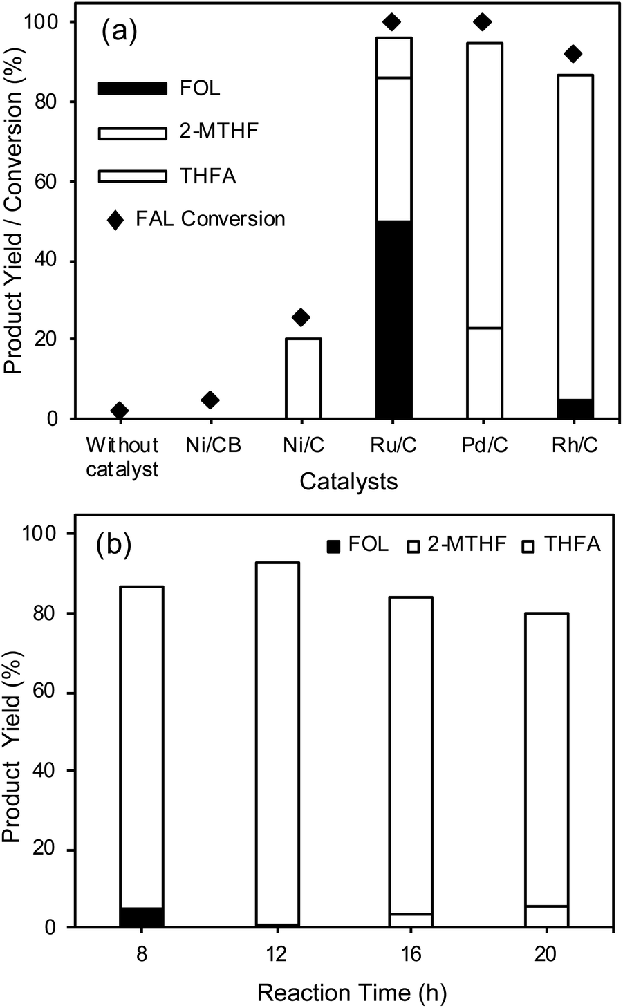 | ||
| Fig. 2 (a) Catalyst evaluation for FAL hydrogenation into THFA, reaction conditions: FAL 60 mg, catalyst 25 mg, H2O 25 mL, H2 pressure 1 MPa, 30 °C, 8 h, stirring speed 600 rpm. (b) Effect of reaction time on FAL hydrogenation. Reaction conditions: FAL 60 mg, Rh/C 25 mg, H2O 25 mL, H2 pressure 1 MPa, 30 °C, stirring speed 600 rpm. | ||
To study the effect of the support, we synthesized an Rh/γ-Al2O3 catalyst using the impregnation method followed by reduction at 450 °C for 5 h and compared its activity with that of the Rh/C catalyst (Fig. S9†). The result showed 86% THFA yield for the hydrogenation of FAL into THFA at 30 °C (8 h) under 1 MPa H2 pressure. Furthermore, we tested FAL hydrogenation using a Ni-supported catalyst with carbon black (CB) and activated carbon (AC) as supports and the results showed that both Ni-supported catalysts are inactive for FAL hydrogenation at 30 °C, suggesting that in the present study the support in the case of the Ni-supported catalyst does not play a significant role; however, in the case of the Rh/γ-Al2O3 catalyst, the γ-Al2O3 support can help to improve the THFA yield.
The effect of time on FAL hydrogenation into THFA was studied using the Rh/C catalyst to enhance the THFA yield, as shown in Fig. 2(b). The results indicate that the THFA yield can be improved to above 82% by increasing the reaction time; an increase in the reaction time from 8 h to 12 h results in an increase in the THFA yield from 82% to 92%. Further, an increase in the reaction time above 12 h results in a gradual decrease in the THFA yield and selectivity due to the conversion of THFA into 2-MTHF. The highest THFA yield can be obtained within 12 h using water as a solvent system at 30 °C. The Rh/C catalyst used in this work shows remarkable efficiency for the selective hydrogenation of FAL into THFA with high THFA yield at ambient temperature. The Rh/C (5 wt% Rh) catalyst exhibits higher efficiency because of its smaller particle size (average particle size of 4.8 nm) and uniform distribution of Rh nanoparticles on the carbon support, better dispersion in water, and higher BET specific surface area (583 ± 10 m2 g−1).
The present study evidently showed that the Rh catalyst has an advantage over the Pd/C catalyst. As shown in Fig. 2(a), the Rh/C catalyst exhibited excellent activity in the selective hydrogenation of FAL to THFA (90% THFA selectivity) in water at 30 °C for 8 h reaction time compared to the Pd/C catalyst (72% THFA selectivity). With an increase in the reaction time from 8 h to 12 h (Fig. 2(b)), the Rh/C catalyst showed an increase in selectivity to 93%. On the other hand, the Pd/C catalyst showed a decrease in THFA selectivity to 60% under similar reaction conditions, indicating that the Rh/C catalyst is highly selective and more active than the Pd/C catalyst. Furthermore, it is also reported that the Pd/C catalyst is not selective for the hydrogenation of FOL (Table 1 entry 3).
| Entry | Substrate (S/C ratio g) | Catalyst | Solvent (mL) | T (°C)/t (h) | Pressure (MPa) | THFA yield (%) | Ref. |
|---|---|---|---|---|---|---|---|
| 1 | FOL (7.5) | Ni/γ-Al2O3 (15 wt% Ni) | Ethanol (53.8) | 80/2 | 4 | 99 | 25 |
| 2 | FOL (10) | Pt/C (5 wt% Pt) | n-Decanol (20) | 160/1 | 3 | 8.6 | 55 |
| 3 | FOL (6.66) | Pd/C (5 wt% Pd) | Water (20) | 160/1 | 3 | 28.3 | 55 |
| 4 | FOL (10) | SnPd/TiO2 (2.5![[thin space (1/6-em)]](https://www.rsc.org/images/entities/char_2009.gif) :2.5 wt%) :2.5 wt%) |
Methanol | 25/1 | 0.1 | 52 | 56 |
| 5 | FAL (7.25) | Ni–Co/SBA-15 | Ethanol (50) | 90/2 | 5 | 92 | 41 |
| 6 | FAL (9.5) | Pd/MFI (3 wt% Pd) | Isopropanol (95) | 220/5 | 3.4 | 83 | 57 |
| 7 | FAL (10) | Pd–Ir–ReOx/SiO2 | Water (9) | 50/2 | 6 | 78 | 8 |
| 8 | FAL (1) | Ni/C-500 derived from Ni-MOF (51 wt% Ni) | 2-Propanol (5) | 120/2 | 1 | 99 | 40 |
| 9 | FAL (9.6) | CuNi/MgAlO | Ethanol (20) | 150/3 | 4 | 95 | 58 |
| 10 | FAL (2.4) | Rh/C (5 wt% Rh) | Water (25) | 30/12 | 1 | 92 | This work |
| 11 | FAL (10) | Rh/C (5 wt% Rh) | Water (25) | 30/8 | 1 | 73 | This work |
| 12 | FAL (2.4) | Rh/C (5 wt% Rh) | DMA (25) | 30/32 | 1 | 95 | This work |
| 13 | FOL (12.8) | Rh/C (5 wt% Rh) | DMA (25) | 30/16 | 0.1 | 96 | This work |
The standards of various possible side products in the case of the FAL hydrogenation reaction such as 2-MF, 2-MTHF, THF, 1,2-PD, and 1,5-PD were analyzed using GC and HPLC. The results indicate the formation of FOL and a small amount of 2-MTHF intermediates using the Rh/C catalyst. Furthermore, the catalytic activity of the Rh/C catalyst was compared for the hydrogenation of FAL and FOL. The comparison of the results of the FAL and FOL hydrogenation reaction suggests that a higher THFA yield (95%) was achieved with the FOL substrate in 8 h whereas a lower THFA yield was obtained (82%) using the FAL substrate under similar reaction conditions. Consequently, the use of the FAL substrate requires a longer reaction time to achieve a higher THFA yield by the one-pot method (92% THFA yield in 12 h). Although FOL hydrogenation to THFA is difficult compared to FAL hydrogenation to FOL, the Rh/C catalyst used in the present work shows excellent activity for the hydrogenation of FOL into THFA under mild reaction conditions (30 °C) in aqueous media. In addition, the Rh/C catalyst performs well for the hydrogenation of FAL to THFA by the one-pot method under mild conditions.
Effect of the solvent system and influence of the reaction time in DMA
The water solvent system was preferred for FAL hydrogenation into THFA because of its environmental benefits and lower cost.50,51 Further, we also studied the effect of other solvent systems including toluene, DMA, and ethanol on FAL hydrogenation into THFA and compared the results with the water solvent system, as shown in Fig. 3(a). The water solvent system shows a higher THFA yield (82%) compared to toluene (8%), DMA (19%), and ethanol (32%). Ethanol and water show a higher THFA yield in 8 h than DMA because ethanol and water have high hydrogen-bond-donation (HBD) capability (α).52 Further, Yoshida et al. reported higher activity for the hydrogenation of acetophenone and 1-phenylethanol in water using the Rh/C catalyst, because of the higher HBD ability (α = 1.17) of water for the Rh/C catalyst.52 Water has a lower hydrogen-bond-acceptance ability (β = 0.18) than polar organic solvents, which also helps to activate the CO functional group of FAL. Furthermore, we studied the effect of stirring speed on FAL hydrogenation using water as the solvent. The result showed a small drop in the THFA yield from 82% to 72% with a decrease in the stirring speed from 600 rpm to 200 rpm, suggesting that the stirring speed influences THFA yield to some extent. In the case of the water solvent, even a lower stirring speed (200 rpm) compared to that of toluene (600 rpm) can provide a higher THFA yield (72%) than that for toluene (8%). Although the high stirring speed in the case of toluene can result in catalyst distribution in toluene, because of the non-polar nature of the solvent, the catalyst does not strongly interact with substrate molecules which are soluble in toluene.
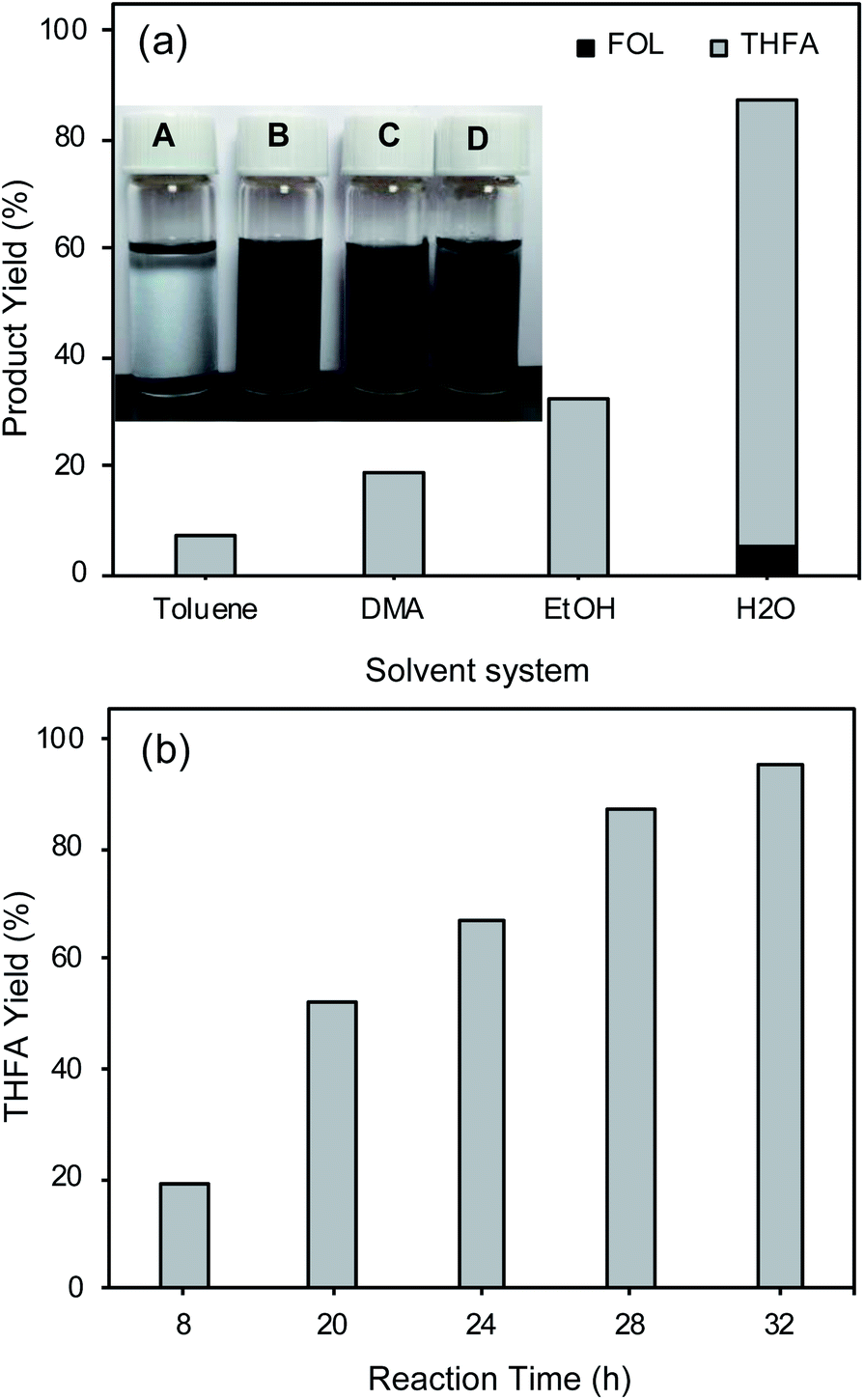 | ||
| Fig. 3 (a) Effect of the solvent and dispersion of Rh/C in various solvents (A = toluene, B = DMA, C = EtOH, and D = H2O). *For the dispersion study 3 mg of the catalyst was dispersed in 3 mL of the solvent; reaction conditions: FAL 60 mg, Rh/C 25 mg, solvent 25 mL, H2 pressure 1 MPa, 30 °C, 8 h, stirring speed 600 rpm. (b) Effect of the reaction time in the DMA solvent on FAL hydrogenation. Reaction conditions: FAL 60 mg, Rh/C 25 mg, DMA 25 mL, H2 pressure 1 MPa, 30 °C, stirring speed 600 rpm. | ||
Further, the water solvent system shows higher THFA yield because of its higher polarity (polarity index = 9) compared to that of other solvents (polarity index of DMA = 6.5, ethanol = 5.2, and toluene = 2.4) and superior dispersion of the Rh/C catalyst in the polar solvent compared to toluene. As shown in the inset of Fig. 3(a), in the case of toluene, the Rh/C catalyst is not well dispersed, while in polar solvent systems (H2O, EtOH, and DMA) the Rh/C catalyst is highly dispersed. For the dispersion study, the picture of the samples was taken after mixing the Rh/C catalyst for 10 min in various solvent systems. The DMA solvent system shows the high dispersion of the Rh/C catalyst because of its higher polarity (6.5) compared to that of ethanol (5.2) and toluene (2.4); therefore, FAL hydrogenation was also studied in the DMA solvent as a function of reaction time (Fig. 3(b)).
As shown in Fig. 3(b), the DMA solvent system can also show superior THFA yield (95%); with increasing the reaction time from 8 h to 32 h, the THFA yield significantly increased from 19% to 95%. However, in this case, to achieve a higher THFA yield a longer reaction time (32 h, 95% THFA yield) was required compared to that of the water solvent system (12 h, 92% THFA yield). The effect of the solvent study shows that the polar solvents are more efficient than non-polar solvents such as toluene for FAL hydrogenation into THFA. The FOL yield and FAL conversion were not calculated in the DMA solvent system because of their close boiling point values (FOL 170 °C, FAL 162 °C, and DMA 165 °C) which leads to overlapping of peaks in the GC chromatogram. Although the DMA solvent system shows a remarkable THFA yield for FAL hydrogenation into THFA by the one-pot method, the use of the DMA solvent system requires a longer reaction time (32 h) compared to that of the water solvent system (12 h). These results indicate that in the DMA solvent system FAL hydrogenation occurs slowly compared to that in the water solvent system.
Furthermore, hydrogenation reactions of FAL and FOL were also carried out under ambient hydrogen pressure and temperature (H2 flow 30 mL min−1, 30 °C) in the DMA solvent system. In this study, in the case of FOL hydrogenation, an increase in the reaction time from 5 h to 16 h results in an increase in the THFA yield from 63% to 95% along with a marginal increase in the 2-MTHF yield to 2% (Fig. S10, ESI†). The reaction performed for 16 h shows the highest THFA yield (95%) along with a small amount of 2-MTHF (2%), while a further increase in the reaction time to 20 h results in a small drop in the THFA yield (92%) because of the increase in the formation of the 2-MTHF side product (4%). The use of the FAL substrate under similar reaction conditions resulted in a 72% THFA yield along with a 5% 2-MTHF yield within 24 h which shows that hydrogenation of FAL into THFA requires a longer reaction time (24 h) compared to FOL hydrogenation (16 h) into THFA, as shown in Fig. S10 and S11.† Similarly, in the case of the water solvent system a higher THFA yield (80%) was achieved within 8 h using FOL under ambient conditions (30 °C, 0.1 MPa H2 pressure, H2 flow 30 mL min−1). The reactions performed in an open system (ambient hydrogen pressure) require a longer time compared to the FAL hydrogenation reaction performed in a closed system (1 MPa hydrogen pressure).
Besides, we also studied the effect of substrate concentration on FAL hydrogenation to THFA under 1 MPa H2 pressure at 30 °C for 8 h, as shown in Fig. S13.† The results indicate a slight decrease in the THFA yield from 82 to 73% with an increase in the substrate concentration from 0.24 to 1 wt%. Further, an increase in the FAL concentration to 4 wt% resulted in a decrease in the THFA yield to 51% along with the generation of an unknown side product in high quantity. The decrease in the THFA yield with an increase in the FAL concentration may be because of its decrease in solubility with an increase in the FAL concentration, and the 8 h reaction time was not sufficient for the complete conversion of FAL into THFA.
Kinetic evaluation showed an increase in the reaction rate (k) with an increase in the reaction temperature from 30 °C (k1 = 3.5 h−1) to 45 °C (k2 = 4.77 h−1) and 60 °C (k3 = 6.76 h−1) over the Rh/C catalyst under ambient H2 pressure (the H2 flow rate 30 mL min−1), as shown Fig. S14(a), ESI.† The reaction rate constant obtained over the Rh/C catalyst at 30 °C under ambient H2 pressure is higher compared to the reported reaction rate constant for FAL hydrogenation to FOL.53 The Hicks group reported an activation energy (EA) of 51.1 kJ mol−1 for FAL hydrogenation into FOL over a Ru1.0MO1.0P catalyst under 4.2 MPa H2 pressure.53 In the present study, the EA calculated using the Arrhenius plot (Fig. S14(b), ESI†) is significantly lower, i.e., 17.7 kJ mol−1 compared to the EA reported by the Hicks group. Further, we have calculated the TOF for the Rh/C catalyst for FAL (1 wt%) hydrogenation into THFA, and the result showed a higher TOF (31 h−1) compared to the reported value for the TOF in the literature for FAL hydrogenation into FOL.25,54 Further, the proposed mechanism for FAL hydrogenation to THFA is presented in Fig. S15.† The kinetic study (Fig. S14(a)†) for FAL hydrogenation using the Rh/C catalyst reveals that the first step is FAL hydrogenation into FOL and then subsequently FOL hydrogenation to THFA.
Comparison of FAL/FOL hydrogenation into THFA using various catalysts
THFA can be obtained by the hydrogenation of the CC double bond of FOL or complete hydrogenation of the CC and CO double bonds of FAL. As mentioned in Table 1, many reports are available for the hydrogenation of FAL and FOL to THFA. Sang S. et al. reported FOL hydrogenation using Ni/γ-Al2O3 (15 wt% Ni) while Milan et al. reported the hydrogenation of FOL using the Pt/C (5 wt% Pt) catalyst (Table 1, entry 1 and 2). The Ni/γ-Al2O3 catalyst exhibited a higher THFA yield (99%) compared to the Pt/C catalyst (46%).25,55 However, these reactions were performed using a higher hydrogen pressure and temperature (Ni/γ-Al2O3, 4 MPa, 80 °C; Pt/C, 3 MPa, 160 °C). Furthermore, FOL hydrogenation to THFA was reported under milder reaction conditions using a SnPd/TiO2 catalyst.56 However, the THFA yield and selectivity obtained with this catalyst are low (THFA yield 52%). Lee et al. reported a highly active monometallic Pd catalyst for the aqueous phase hydrogenation of FOL into THFA.54 However, the reaction was carried out with FOL instead of FAL and required a higher H2 pressure (5.5 MPa) at 80 °C, while in the present study, hydrogenation reactions were carried out with the FAL substrate by the one-pot method under ambient conditions.
In the case of hydrogenation of FAL to THFA, excellent THFA yield (99% yield) was reported using a MOF-derived Ni/C catalyst (51 wt% Ni).40 Although this Ni-based catalyst showed a high yield of THFA, the drawback associated with this method is higher reaction temperature and hydrogen pressure (120 °C, 1 MPa). Consequently, the use of a MOF derived catalyst gives rise to several issues, such as MOF-derived materials being obtained on a lab scale with lower yields and the synthesis process being time-consuming.59 Liu et al. reported a Rh–Ir–ReOx/SiO2 alloy catalyst for the hydrogenation of furfural. The results indicated a 66.8% THFA yield at 50 °C in 8 h. However, it requires a reduction pretreatment of the catalyst at 200 °C under high H2 pressure (8 MPa).60 Furthermore, a Pd supported on MFI-type zeolite (Pd/MFI) catalyst reported for the hydrogenation of FAL requires a higher temperature and hydrogen pressure (220 °C, 3.4 MPa).57 Similarly, other catalysts mentioned in Table 1 require a higher reaction temperature and pressure; furthermore, an organic solvent system was used for many reactions. All these issues can be resolved using the Rh/C catalyst for the hydrogenation of FAL into THFA. The Rh/C catalyst shows excellent activity for the selective hydrogenation of FAL into THFA by the one-pot method under mild reaction conditions (30 °C) in an aqueous solvent (Table 1, entry 10) with a high THFA yield (92%). Furthermore, Rh/C showed a high THFA yield (95%) in the DMA solvent (Table 1, entry 12). Thus, the Rh/C catalyst investigated for the hydrogenation of FAL exhibits high activity for the selective hydrogenation of FAL to THFA under mild reaction conditions. Further, HMF hydrogenation was carried out using the Rh/C catalyst at 30 °C for 8 h under ambient H2 pressure (H2 flow 30 mL min−1), and the results showed the formation of 2,5-bis(hydroxymethyl)furan in high yield (ca. 70%).
The Rh/C catalyst was separated from the reaction solution and characterized using various physicochemical characterization techniques to check the stability of the Rh/C catalyst under the reaction conditions. The separated Rh/C catalyst was dried at 120 °C for 16 h and then characterized using XRD, TEM, and N2-adsorption–desorption characterization techniques. The TEM study of fresh and recycled Rh/C catalysts confirms that the morphologies of the recycled Rh/C catalyst and fresh Rh/C catalyst are similar (Fig. 1(a) and 4(a)). Similarly, the BET specific surface area of the recycled Rh/C catalyst was 562 m2 g−1 which is similar to the BET specific surface area of the fresh Rh/C catalyst (SBET = 583 m2 g−1). As shown in Fig. 4(b) and S1,† the XRD patterns of the fresh and recycled Rh/C catalysts are identical, suggesting that the Rh/C catalyst is stable under the reaction conditions and can be used in the recycling experiment without a loss in activity.
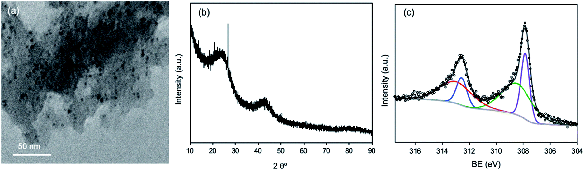 | ||
| Fig. 4 (a) TEM images of the recycled Rh/C catalyst, (b) XRD pattern of the recycled Rh/C catalyst, and (c) XPS spectrum of Rh 3d for the recycled Rh/C catalyst. | ||
The XPS examination of the recycled Rh/C catalyst shows peaks at BEs of 308.6 eV and 313.6 which correspond to the oxidized state of Rh while the peaks at BEs of 307.6 eV and 312.3 eV correspond to the metallic state of Rh (Fig. 4(c)).43 The recycled Rh/C catalyst has a similar Rh chemical status to that obtained for the fresh Rh/C catalyst (Fig. S3(a)†). However, we have observed some adsorption (ca. 4–5%) of furans (FAL, FOL, and THFA) on the recycled catalyst. The catalyst can be activated using high-temperature reduction under a hydrogen flow. The reduction will also help in the activation of the catalyst by increasing the amount of metallic Rh. We have carried out the recycling experiment without reducing the catalyst. For the recycling experiment performed using the Rh/C catalyst for the hydrogenation of FAL into THFA in an aqueous medium, 90% THFA yield (first run) and 86% THFA yield (second run) were achieved indicating that the Rh/C catalyst shows a nearly consistent high catalytic activity during the recycling experiment.
Conclusions
In summary, we have investigated the use of the Rh/C catalyst for the selective hydrogenation of FAL into THFA under mild reaction conditions in aqueous media. The Rh/C catalyst exhibits improved activity compared to other supported metal catalysts such as Ru/C, Pt/AC, and Pd/C for the hydrogenation of FAL to THFA. The results indicated that the Rh/C catalyst exhibits high performance for the ring hydrogenation of FOL under milder reaction conditions which leads to its superior activity for the hydrogenation of FAL into THFA by a one-pot method. The Rh/C catalyst was characterized in detail using several characterization techniques (XRD, XPS, TEM/EDS, N2-adsorption–desorption, and ICP-OES). The small particle size (4.8 nm), uniform distribution of Rh, high BET specific surface area (583 m2 g−1), and better dispersion in water and a DMA solvent system makes the Rh/C catalyst highly active for FAL hydrogenation. The Rh/C catalyst used for FAL hydrogenation is stable and can be employed in recycling experiments without any loss in the performance. The Rh/C catalyst is commercially produced, which would enable its utilization on a large-scale in many other hydrogenation reactions.Conflicts of interest
There are no conflicts to declare.Acknowledgements
The authors would like to thank the Ministry of Science and Technology (MOST), Taiwan (104-2628-E-002-008-MY3; 105-2221-E-002-227-MY3; 105-2218-E-155-007; 105-2221-E-002-003-MY3; 105-2622-E155-003-CC2), the Researchers Support Project (RSP-2019/6), King Saud University, Riyadh, Saudi Arabia, and the Aim for Top University Project at National Taiwan University (105R7706; 107L2033-32; 107L891204; 107L7703; 107L104312; 107L7828) for the funding support.Notes and references
- X. Li, P. Jia and T. Wang, ACS Catal., 2016, 6, 7621–7640 CrossRef CAS.
- B. M. Matsagar, S. A. Hossain, T. Islam, H. R. Alamri, Z. A. Alothman, Y. Yamauchi, P. L. Dhepe and K. C. W. Wu, Sci. Rep., 2017, 7, 13508 CrossRef.
- B. M. Matsagar and P. L. Dhepe, New J. Chem., 2017, 41, 6137–6144 RSC.
- R. Karinen, K. Vilonen and M. Niemelä, ChemSusChem, 2011, 4, 1002–1016 CrossRef CAS.
- B. M. Matsagar and P. L. Dhepe, Catal. Sci. Technol., 2015, 5, 531–539 RSC.
- K. Yan, G. Wu, T. Lafleur and C. Jarvis, Renewable Sustainable Energy Rev., 2014, 38, 663–676 CrossRef CAS.
- Y.-T. Liao, B. M. Matsagar and K. C. W. Wu, ACS Sustainable Chem. Eng., 2018, 6, 13628–13643 CrossRef CAS.
- S. Liu, Y. Amada, M. Tamura, Y. Nakagawa and K. Tomishige, Green Chem., 2014, 16, 617–626 RSC.
- B. M. Matsagar, M. K. Munshi, A. A. Kelkar and P. L. Dhepe, Catal. Sci. Technol., 2015, 5, 5086–5090 RSC.
- M. Dohade and P. L. Dhepe, Catal. Sci. Technol., 2018, 8, 5259–5269 RSC.
- P. Panagiotopoulou and D. G. Vlachos, Appl. Catal., A, 2014, 480, 17–24 CrossRef CAS.
- F. Liu, Q. Liu, J. Xu, L. Li, Y.-T. Cui, R. Lang, L. Li, Y. Su, S. Miao, H. Sun, B. Qiao, A. Wang, F. Jérôme and T. Zhang, Green Chem., 2018, 20, 1770–1776 RSC.
- S. Dutta, S. De, B. Saha and M. I. Alam, Catal. Sci. Technol., 2012, 2, 2025–2036 RSC.
- Y. Nakagawa, M. Tamura and K. Tomishige, J. Jpn. Pet. Inst., 2017, 60, 1–9 CrossRef CAS.
- M. Douthwaite, X. Huang, S. Iqbal, P. J. Miedziak, G. L. Brett, S. A. Kondrat, J. K. Edwards, M. Sankar, D. W. Knight, D. Bethell and G. J. Hutchings, Catal. Sci. Technol., 2017, 7, 5284–5293 RSC.
- S. R. Kubota and K.-S. Choi, ACS Sustainable Chem. Eng., 2018, 6, 9596–9600 CrossRef CAS.
- N. K. Gupta, A. Fukuoka and K. Nakajima, ACS Sustainable Chem. Eng., 2018, 6, 3434–3442 CrossRef CAS.
- K. Tomishige, Y. Nakagawa and M. Tamura, Green Chem., 2017, 19, 2876–2924 RSC.
- Y. Nakagawa, H. Nakazawa, H. Watanabe and K. Tomishige, ChemCatChem, 2012, 4, 1791–1797 CrossRef CAS.
- S. Bhogeswararao and D. Srinivas, J. Catal., 2015, 327, 65–77 CrossRef CAS.
- M. A. Tike and V. V. Mahajani, Ind. Eng. Chem. Res., 2007, 46, 3275–3282 CrossRef CAS.
- Q. Yuan, F. Ye, T. Xue and Y. Guan, Appl. Catal., A, 2015, 507, 26–33 CrossRef CAS.
- M. Chia, Y. J. Pagán-Torres, D. Hibbitts, Q. Tan, H. N. Pham, A. K. Datye, M. Neurock, R. J. Davis and J. A. Dumesic, J. Am. Chem. Soc., 2011, 133, 12675–12689 CrossRef CAS.
- S. Koso, N. Ueda, Y. Shinmi, K. Okumura, T. Kizuka and K. Tomishige, J. Catal., 2009, 267, 89–92 CrossRef CAS.
- S. Sang, Y. Wang, W. Zhu and G. Xiao, Res. Chem. Intermed., 2017, 43, 1179–1195 CrossRef CAS.
- Y. Nakagawa and K. Tomishige, Catal. Today, 2012, 195, 136–143 CrossRef CAS.
- L. Li, K. J. Barnett, D. J. McClelland, D. Zhao, G. Liu and G. W. Huber, Appl. Catal., B, 2019, 245, 62–70 CrossRef CAS.
- Z. J. Brentzel, K. J. Barnett, K. Huang, C. T. Maravelias, J. A. Dumesic and G. W. Huber, ChemSusChem, 2017, 10, 1351–1355 CrossRef CAS PubMed.
- R. Huang, Q. Cui, Q. Yuan, H. Wu, Y. Guan and P. Wu, ACS Sustainable Chem. Eng., 2018, 6, 6957–6964 CrossRef CAS.
- Y. Nakagawa and K. Tomishige, Catal. Commun., 2010, 12, 154–156 CrossRef CAS.
- H. Guo, H. Zhang, L. Zhang, C. Wang, F. Peng, Q. Huang, L. Xiong, C. Huang, X. Ouyang, X. Chen and X. Qiu, Ind. Eng. Chem. Res., 2018, 57, 498–511 CrossRef CAS.
- M. Manikandan, A. K. Venugopal, K. Prabu, R. K. Jha and R. Thirumalaiswamy, J. Mol. Catal. A: Chem., 2016, 417, 153–162 CrossRef CAS.
- H. Wang, X. Li, X. Lan and T. Wang, ACS Catal., 2018, 8, 2121–2128 CrossRef CAS.
- Y. Yang, J. Ma, X. Jia, Z. Du, Y. Duan and J. Xu, RSC Adv., 2016, 6, 51221–51228 RSC.
- A. S. Gowda, S. Parkin and F. T. Ladipo, Appl. Organomet. Chem., 2012, 26, 86–93 CrossRef CAS.
- F.-A. Khan, A. Vallat and G. Süss-Fink, Catal. Commun., 2011, 12, 1428–1431 CrossRef CAS.
- Y. Nakagawa, K. Takada, M. Tamura and K. Tomishige, ACS Catal., 2014, 4, 2718–2726 CrossRef CAS.
- L. Liu, H. Lou and M. Chen, Int. J. Hydrogen Energy, 2016, 41, 14721–14731 CrossRef CAS.
- C. Li, G. Xu, X. Liu, Y. Zhang and Y. Fu, Ind. Eng. Chem. Res., 2017, 56, 8843–8849 CrossRef CAS.
- Y. Su, C. Chen, X. Zhu, Y. Zhang, W. Gong, H. Zhang, H. Zhao and G. Wang, Dalton Trans., 2017, 46, 6358–6365 RSC.
- S. Li, Y. Wang, L. Gao, Y. Wu, X. Yang, P. Sheng and G. Xiao, Microporous Mesoporous Mater., 2018, 262, 154–165 CrossRef CAS.
- B. M. Matsagar, T.-C. Kang, Z.-Y. Wang, T. Yoshikawa, Y. Nakasaka, T. Masuda, L.-C. Chuang and K. C. W. Wu, React. Chem. Eng., 2019, 4, 618–626 RSC.
- B. M. Matsagar, Z.-Y. Wang, C. Sakdaronnarong, S. S. Chen, D. C. W. Tsang and K. C. W. Wu, ChemCatChem, 2019, 11, 4604–4616 CrossRef CAS.
- F. T. Johra, J.-W. Lee and W.-G. Jung, J. Ind. Eng. Chem., 2014, 20, 2883–2887 CrossRef CAS.
- C. Lin, G. Wu, H. Li, Y. Geng, G. Xie, J. Yang, B. Liu and J. Jin, Nanoscale, 2017, 9, 1834–1839 RSC.
- M. E. Halttunen, M. K. Niemelä, A. O. I. Krause, T. Vaara and A. I. Vuori, Appl. Catal., A, 2001, 205, 37–49 CrossRef CAS.
- A. Talo, J. Lahtinen and P. Hautojärvi, Appl. Catal., B, 1995, 5, 221–231 CrossRef CAS.
- Z. Weng-Sieh, R. Gronsky and A. T. Bell, J. Catal., 1997, 170, 62–74 CrossRef CAS.
- C. V. Rode, U. D. Joshi, O. Sato and M. Shirai, Chem. Commun., 2003, 1960–1961 RSC.
- B. M. Matsagar, C. Van Nguyen, M. S. A. Hossain, M. T. Islam, Y. Yamauchi, P. L. Dhepe and K. C. W. Wu, Sustainable Energy Fuels, 2018, 2, 2148–2153 RSC.
- H. Yang, G. Gözaydın, R. R. Nasaruddin, J. R. G. Har, X. Chen, X. Wang and N. Yan, ACS Sustainable Chem. Eng., 2019, 7, 5532–5542 CrossRef CAS.
- H. Yoshida, Y. Onodera, S.-i. Fujita, H. Kawamori and M. Arai, Green Chem., 2015, 17, 1877–1883 RSC.
- Y. Bonita, V. Jain, F. Geng, T. P. O'Connell, W. N. Wilson, N. Rai and J. C. Hicks, Catal. Sci. Technol., 2019, 9, 3656–3668 RSC.
- J. Lee, Y. Xu and G. W. Huber, Appl. Catal., B, 2013, 140–141, 98–107 CAS.
- M. Hronec, K. Fulajtarová and T. Liptaj, Appl. Catal., A, 2012, 437–438, 104–111 CrossRef CAS.
- G. M. King, S. Iqbal, P. J. Miedziak, G. L. Brett, S. A. Kondrat, B. R. Yeo, X. Liu, J. K. Edwards, D. J. Morgan, D. K. Knight and G. J. Hutchings, ChemCatChem, 2015, 7, 2122–2129 CrossRef CAS.
- N. S. Biradar, A. M. Hengne, S. N. Birajdar, P. S. Niphadkar, P. N. Joshi and C. V. Rode, ACS Sustainable Chem. Eng., 2014, 2, 272–281 CrossRef CAS.
- J. Wu, G. Gao, J. Li, P. Sun, X. Long and F. Li, Appl. Catal., B, 2017, 203, 227–236 CrossRef CAS.
- K. Shen, X. Chen, J. Chen and Y. Li, ACS Catal., 2016, 6, 5887–5903 CrossRef CAS.
- S. Liu, Y. Amada, M. Tamura, Y. Nakagawa and K. Tomishige, Catal. Sci. Technol., 2014, 4, 2535–2549 RSC.
Footnotes |
| † Electronic supplementary information (ESI) available. See DOI: 10.1039/c9se00681h |
| ‡ The first two authors contributed to this work equally. |
| This journal is © The Royal Society of Chemistry 2020 |