
Layer-by-layer assembly for immobilizing enzymes in enzymatic biofuel cells
Jiru
Zhang
a,
Xingcan
Huang
a,
Lili
Zhang
*b,
Yawei
Si
b,
Shuai
Guo
a,
Hang
Su
a and
Jian
Liu
 *a
*a
aSchool of Control Science and Engineering, Shandong University, Jinan, 250061, China. E-mail: lj@sdu.edu.cn
bSchool of Mechanical and Automotive Engineering, Qilu University of Technology, Jinan, 250353, China. E-mail: sdilizll@163.com
First published on 11th October 2019
Abstract
Various methods of immobilizing enzymes on electrodes have been developed for the research of enzymatic biofuel cells (EBFCs). Among these methods, the layer-by-layer (LbL) assembly is a delicate technology that can form controllable enzyme layers and load a high density of enzyme molecules by electrostatic deposition, hydrogen bonding, or covalent bonding. In this paper, recent advancements of the LbL assembly for immobilizing enzymes in EBFCs are presented in detail. First, the LbL formation mechanism of a multilayer sensitive film on electrodes is analyzed, and the potential of the multilayer structure is also discussed. Then, the applications of enzyme immobilization by the LbL assembly in combination with various materials in EBFCs are investigated. The power density of LbL assembly-based EBFCs increases by several orders of magnitude with the widespread use of nanomaterials. As a convenient and efficient operation, the LbL assembly technology is expected to become a popular method for immobilizing enzymes in EBFCs.
 Jiru Zhang | Jiru Zhang is a Master's student in the Department of Biomedical Engineering, Shandong University. He received his Bachelor's degree in Biomedical Engineering from Chongqing University of Technology. His areas of expertise include the application of enzymatic biofuel cells. |
 Xingcan Huang | Xingcan Huang is a Master's student in the Department of Biomedical Engineering, Shandong University. He received his Bachelor's degree in Measurement and Control Technology and Instruments from Qingdao University. His interests include the mechanism of enzymatic biofuel cells. |
 Lili Zhang | Lili Zhang is an Associate Professor at the School of Mechanical and Automotive Engineering, Qilu University of Technology. She received her PhD in Mechanical Engineering from Shandong University. Her interests are focused on sensors and microfluidics in biomedical engineering. |
 Yawei Si | Yawei Si is a Master's student in the Department of Mechanical & Automotive Engineering, Qilu University of Technology. He obtained his Bachelor's degree from the Qilu University of Technology. His scientific interests are focused on microfluidics in biomedical engineering. |
 Shuai Guo | Shuai Guo is a Master's student in the Department of Biomedical Engineering, Shandong University. He received his Bachelor's degree from the Faculty of Electronic Information and Electrical Engineering, Dalian University of Technology. His research interests are focused on biochemical measurement. |
 Jian Liu | Jian Liu is an Associate Professor at the School of Control Science and Engineering, Shandong University. He received his PhD in Bioelectronics from the Institute of Electrics, Chinese Academy of Sciences. His interests include biomedical sensors and enzymatic biofuel cells. |
1. Introduction
Nowadays, owing to the great demand for energy, there has been deep and extensive research on renewable energy.1–4 Biofuel cells, converting chemical energy into electrical energy by redox reactions, are very promising portable power sources owing to their high efficiency and environmental friendliness. According to the catalysts, biofuel cells are classified into microbial fuel cells (MBFCs),5 enzymatic biofuel cells (EBFCs)6 and organelle biofuel cells (OBFCs).7 Compared with MBFCs and OBFCs, EBFCs have higher power efficiency because enzymes are directly used as catalysts without the obstruction of microbial shells and cell walls. In addition, the commonly used enzymes are oxidases or dehydrogenases with glucose, ethanol or others as fuels.8 In addition, EBFCs can ensure security because of the mild reaction conditions, i.e., at normal temperature and pressure.The first EBFC was invented by Yahiro with glucose oxidase (GOx) as a bioanode and platinum as a cathode in 1964.9 Thereafter, scientists carried out many studies to promote the development of EBFCs. Until today, the EBFCs had not been used outside the laboratory due to their low efficiency of electron transfer between the electrode and the redox center of the enzyme. There are two common ways, namely, direct electron transfer (DET) and mediated electron transfer (MET). DET refers to enzymes connected on the electrode surface for transferring electrons directly between the enzyme activity center and the electrode. On the contrary, MET means that electrons are shuttled from the electrode to the enzyme by a third chemical species, the redox mediator.10 Although the mediator can increase the electron transfer rate, it also introduces the adverse effects of overpotential. In the early study, the enzyme was usually dispersed in the solution with a free-state.11 However, the redox reaction of the enzyme in the solution was unstable, and the electron transfer in the solution was difficult. Furthermore, it was difficult to recover and reuse the enzyme after the reaction. The low power density and short-term stability were key issues that scientists had to solve at that time. Plotkin and Persson found that the performance of EBFCs was improved when enzymes were immobilized on the electrode.12,13 Through a series of investigations, it was found that the immobilization of enzymes on the surface of the electrode was a crucial element, which not only increased the current/power density, but also prolonged the lifetimes of biofuel cells.14,15
In order to address the above-mentioned problems, researchers have tried to develop various enzyme immobilization methods16 including physical adsorption,17 crosslinking,18 embedding,19 electrochemical polymerization20 and layer-by-layer (LbL) assembly,21 as shown in Fig. 1. Physical adsorption mainly uses porous materials to adsorb enzymes, which can effectively maintain the activity of enzymes.17 However, the electrode based on physical adsorption is unstable because the enzyme cannot be firmly adsorbed. The crosslinking reaction is a common strategy for immobilizing enzymes, which has good stability with the assistance of cross-linkers.18 Nevertheless, it is important to consider that crosslinking requires complicated operations.22 Electrochemical polymerization is another way to immobilize enzymes on the electrode.20 The monomer molecules with a functional group undergo a polymerization reaction on the electrode at a certain external potential. During electrochemical polymerization, enzymes act as intermediates and interact with the main chain of the polymer. Therefore, when monomer molecules are polymerized on the surface of the electrode, enzymes are also immobilized on the electrode. Embedding is an ideal immobilization method that allows the enzyme to be directly captured into a polymer (sol–gel, mesoporous carbon, conductive polymer, etc.).23–25 This method preserves the structure of enzymes and maintains the stability of the redox reaction. However, some polymers can hinder the intimate contact of macromolecular analytes with enzymes. Among these methods, the LbL assembly is a novel technology controllably immobilizing enzymes with a three-dimensional (3D) multilayer structure, which showed better activity and easier operability. In contrast to previous methods, the LbL assembly can accurately and controllably increase the loading of the enzyme onto the electrode surface. This review describes EBFCs based on the LbL assembly, with an emphasis on improving enzyme immobilization by combining with various materials.
 | ||
| Fig. 1 Schematic of different enzyme immobilization methods. | ||
2. LbL assembly for immobilizing enzymes
2.1. Mechanisms of LbL assembly
The LbL assembly is a delicate technique for depositing multilayer films, which has attracted great attention of scientists owing to its prospects in the fields of biology and molecular science.26–28 Multilayer film materials can be assembled in a variety of 2D or 3D substrates, such as silicon wafers, plastic surfaces and colloidal particles.29 The thin-film based on the LbL assembly can be formed by various interactions such as electrostatic interactions,30 hydrogen bonding,31 covalent bonding32 and host–guest interactions.33 According to the characteristics of these interactions, they can be applied in different research areas.33–35The LbL assembly was developed following the self-assembled monolayer technology and Langmuir–Blodgett deposition film technology.36,37 In 1966, Iler used the alternating deposition of opposite charges to prepare a thin-film, while the lack of proper methods for characterizing the thin-film limited its further growth at the time.38 Until 1991, Decher pioneered the concept of LbL assembly by depositing multilayer films with opposite-charged polyelectrolytes on a charged surface.39–43 The principle and preparation of the LbL assembly were simple with four essential steps, as described in Fig. 2A. As a substrate material, the charged surface was initially prepared mainly by some surface modification methods such as oxidation reactions or plasma treatment.44 The modified substrate material was first immersed into a suspension containing polyanions (step 1), and then washed in a solvent to remove the unbound polyelectrolytes (step 2). The substrate with polyanions on the surface was subsequently immersed into a suspension containing polycations (step 3) and then washed (step 4). The preparation process at the molecular level demonstrated that a positively charged substrate could continuously adsorb polyanions and polycations (Fig. 2B). Repeating the above four steps, the polyanion and the polycation were alternately deposited by electrostatic interactions to obtain a multilayer film structure. This was attributed to excessive surface charges and charge reversal in each layer.45,46 The thickness of the film had a linear relationship with the number of depositions, and each layer could only interact with the three neighboring layers on each side.47 Because of its generalizability and significance, electrostatic interactions can be used as a simple but powerful approach to ameliorate the architecture design.48 Due to the non-specificity of electrostatic interactions, functional materials such as conductive polymers49 and biomacromolecules50 can be used to functionalize the multilayer film. Zhuang and his colleagues experimentally verified that electrostatic interactions can assemble polyelectrolytes into programmable nanocomponents.51 In the electrolyte solution, the multilayer structure remains electroneutral due to the exchange of ions and solvent with the external electrolyte, thereby avoiding the influence of additional potential.52 The nanoassembly can be functionalized to create a multifunctional surface that permanently controls the properties of the interface. It is worth noting that multilayer structures based on electrostatic interactions can maintain stability within the normal pH range, but multilayer structures are also destroyed under extreme conditions (high pH or high concentration salt solution).53
 | ||
| Fig. 2 (A) Schematic of the film deposition process using slides and beakers. Steps 1 and 3 represent the adsorption of a polyanion and a polycation, respectively, and steps 2 and 4 are washing steps. The four steps are the basic buildup sequence for the simplest film architecture, (A/B)n. The construction of more-complex film architectures requires only additional beakers and a different deposition sequence. (B) Simplified molecular picture of the first two adsorption steps, depicting film deposition starting with a negatively charged substrate. The polyion conformation and layer interpenetration are an idealization of the surface-charge reversal with each adsorption step. Reprinted with permission from ref. 39, copyright 1997, The American Association for the Advancement of Science. | ||
Although the LbL assembly technique based on electrostatic interactions is widely used, there are still some limitations on the type of film-forming materials. For instance, the electrostatic interaction requires that the layer must be charged. Therefore, some scientists began to explore the possibility of other interactions in LbL-assembled films. In 1997, Stockton and Rubner first reported a hydrogen bond-based LbL assembly, which was a reversible non-covalent bonding force to bind polyions and colloids together.54 Hydrogen bonding could be used to form supramolecular compounds in assembly systems.55 The advantages of hydrogen bonding in multilayer structures were reversibility and no electrostatic repulsion, but this application was also susceptible to pH values.56 Ono et al. explored the hydrogen bond's response to pH and found that the changes in pH would affect hydrogen bonding.57,58 Besides, covalent bonding has been used in the LbL assembly in recent years, which mainly relies on the reaction between polymers. The bond energy of covalent bonding is higher than that of electrostatic interactions or hydrogen bonding.59 The host–guest interaction is a common assembly technique in supramolecular chemistry. It refers to the formation of supramolecular inclusion complexes between two or more entities connected in a highly controllable and cooperative manner.33 Depending on the flexibility and versatility of multilayer structures, the LbL assembly continues to be practiced in the application of new materials.60 It is widely used in many fields, such as separation membranes,61,62 drug delivery systems,63 optoelectronic devices,64 biosensors53 and bioreactors.65
2.2. Immobilization of enzymes in EBFCs
The LbL assembly has become a rapidly evolving technology for immobilizing enzymes in EBFCs. In 1996, Onda et al. pioneered the multilayer structure of GOx assembled via electrostatic interaction.66,67 Rao and his partners proposed that biotinylated horseradish peroxidase (HRP) attached with avidin via the avidin-biotin interaction.68 Since then, the LbL assembly has been used in EBFCs with efficient electron transfer and high enzymatic loading. Moreover, electrostatic interaction and covalent bonding became common immobilization methods in EBFCs because of their ability to promote electron transfer and improve the multilayer structure stability. Until now, except for the drug delivery system, hydrogen bonding and host–guest interactions have not been used in LbL assembly-based EBFCs.69Meanwhile, many studies on the enzyme-modified electrode have also been flourishing for enhancing the performance of EBFCs.16 When scientists choose the best immobilization method, there are two issues to be considered: one is that the redox reaction in EBFCs should be steady and efficient and the other is that the electron transfer between the enzyme and the electrode should be unaffected. As a novel method of immobilizing enzymes, the LbL assembly depends on the spontaneous interaction between molecules to form multilayer structures.21 Compared with other methods of immobilizing enzymes, the advantages of the LbL assembly include: simple process and equipment, suitability of most coating surfaces, diversity of natural and artificial materials, long-term stability of the system, and controllability of coating thickness.70,71 Moreover, the same process can be used to immobilize enzymes on the anode and cathode in EBFCs based on the LbL assembly, which makes the LbL assembly applicable in different scenarios. Enzyme immobilization is the core issue in the field of EBFCs, and its exploration has never stopped.
2.3. Characterization methods of the LbL assembly
Scientists have established a variety of characterization techniques such as the film thickness, surface roughness, and the formation of each layer to investigate the properties of multilayer film nanostructures.72First, the morphology of multilayers can be analyzed by transmission electron microscopy (TEM), which is usually used as a tool to observe nanostructures. In EBFCs, a visual image showing the state of the electrode surface modification can be obtained by TEM. The results indicate that the diameter of [GOx/PEI]n/CNT is much larger than that of the bare CNT, indicating that the surface of CNT is covered with a multilayer structure (Fig. 3A).71 Additionally, electrochemical methods for characterizing the modified electrode are able to qualitatively and quantitatively describe the modification process and electrode performance through the chemical reactions. Cyclic voltammetry (CV) and electrochemical impedance spectroscopy (EIS) are the most commonly used tools for the analysis of LBL-assembled electrodes in EBFCs.72 CV controls the electrode potential at different rates and scans the electrode potential repeatedly with one or more triangular waveforms. In this method, different reduction and oxidation reactions occur alternately on the electrode, and current–potential curves are recorded. In this case, the redox peak current of the modified electrode increased with the increase in GA/[GOx/PANI/CNT]n layers, which confirmed the formation of the multilayer structure (Fig. 3B). EIS exerts a sinusoidal potential signal to the electrode to measure the impedance changes at different frequencies. The Nyquist diagram obtained by EIS reflects the good load of enzyme on the multilayer structure.73 According to the EIS measurement, as GA/[GOx/PANI/CNT]n layers (n = 1, 2, 3 and 4) increased, its Rct also increased (Fig. 3B). Since GOx is known as a non-conductive material, Rct should be proportional to the amount of GOx.74 The current density and impedance in electrochemical detection can be used as indicators to confirm the immobilization of enzymes via the LbL assembly. Furthermore, some optical technologies are devoted to monitoring the growth of the multilayer film as well. UV spectroscopy can quantify the loading efficiency of the nanoparticles or proteins. As the [GOx/PANI/CNT]n layers increased, the absorbance peak at 460 nm also increased because the magnitude of the absorption peak depends on the loading amount of GOx (Fig. 3C).74 Moreover, the zeta (ζ) potential measurement could be used to understand the situation of each layer of charged particles under electrostatic adsorption. As shown in Fig. 3D, it was important to measure the polarization direction of each GOx, PANI and CNT component because the formation of the GA/[GOx/PANI/CNT]n layers was attributed to the appropriate alternation in the polarization. That is, CNT and GOx were supposed to take on a negative charge, while PANI should take on a positive charge.74 Meanwhile, other tools such as scanning electron microscopy (SEM),75 X-ray reflectometry (XRR),76 X-ray photoelectron spectroscopy (XPS)71 and quartz crystal microbalance (QCM) were also applied to monitor the film thickness and the process of formation.77,78
 | ||
| Fig. 3 Schematic of the characterization methods for the LbL assembly: (A) TEM images of bare CNT (a) and [GOx/PEI]2/CNT (b). Reprinted with permission from ref. 71, copyright 2015, Elsevier. (B) Cyclic voltammograms (a) and EIS measurements (b) of GA/[GOx/PANI/CNT]n layers (n = 1, 2, 3 and 4). In the tests, 0.01 M PBS (pH 7.4) was served as the electrolyte and the potential scan rate was 100 mV s−1. (C) Absorbance peaks of GA/[GOx/PANI/CNT]n layers (n = 1, 2, 3 and 4) measured using a UV spectrophotometer (inset shows absorbance peaks measured at 460 nm of the four GA/[GOx/PANI/CNT]n layers). (D) Changes in polarization of alternately deposited PANI/CNT and GOx in [GOx/PANI/CNT]n layers (n = 1 and 2). Reprinted with permission from ref. 74, copyright 2015, Elsevier. | ||
3. Application of the LbL assembly in EBFCs with various coating materials
The LbL assembly provides a new option for the immobilization of enzymes in EBFCs, which is simpler and more robust. In practical applications, glassy carbon (GC) electrodes, platinum electrodes and carbon paper electrodes are usually used as the substrate for LbL assembly-based EBFCs. Considering the need to establish a good connection between enzymes and electrode, researchers have investigated various coating materials to immobilize enzymes on the surface of electrodes.3.1. Carbon nanomaterials
CNT-based electrodes prepared via LbL assembly were efficient for the design of powerful EBFCs. CNTs were used as a support for high loading and dispersion of enzymes on the electrode. For example, a fast and simple self-powered biosensor for cyanide detection was developed based on a CNTs/laccase biocathode.82 CNTs were modified into a hydrophilic surface with functional groups, which could be adsorbed on the electrode surface and combined with enzymes. The 3D support structure of carbon nanotubes used in the LbL assembly not only facilitated the adsorption of various substances including enzymes and other materials, but also provided a stable system to extend the life of EBFCs. It was worth noting that the purity of CNTs was higher than 90%. Two different LbL-assembled structures were commonly used, and CNTs played different roles in the two structures. One method was to use the electrode as the bottom layer of the multilayer structure, and then alternately stacked each layer on top with the layer of CNTs, enzymes and polyelectrolytes. This method usually modified the electrode by immersion83,84 or coating.85 The other method was to use the CNTs as the bottom layer to stack other layers, and the resulting multilayer structure would be used to modify the electrode. First, CNTs were immersed in the polyelectrolyte solution, the obtained mixtures were rinsed and then immersed in the enzyme solution, and the finally obtained hybrid was adsorbed on the electrode surface.71
In the last few years, graphene and RGO also contributed to the evolution of LbL assembly-based EBFCs. Wang constructed on-chip, mediator- and membrane-less glucose biofuel cells based on the LbL assembly with RGO-enzyme hybrids.89 First, 12 interdigital Au fingers (6 fingers as anodes and cathodes, respectively) were deposited on a glass slide as a substrate. Bioanodes and biocathodes could be prepared by the electrochemical reduction in the solutions of graphene oxide (GO) and enzymes. During the bioelectrode fabrication, 30 mg GOx was added to the GO dispersion (3 mg mL−1) and the resulting mixture was stirred for 30 minutes. Through this method, the RGO-enzyme sandwich structure could be obtained as shown in Fig. 4. Such a special LbL structure could effectively trap enzymes and ensure a high enzyme loading. It could accelerate the transport of ions and electrons as well. The maximum power density of the device was 14.77 mW cm−3, which showed excellent performance. This EBFC demonstrated a great potential for applications in miniaturized devices (wearable or even implantable).
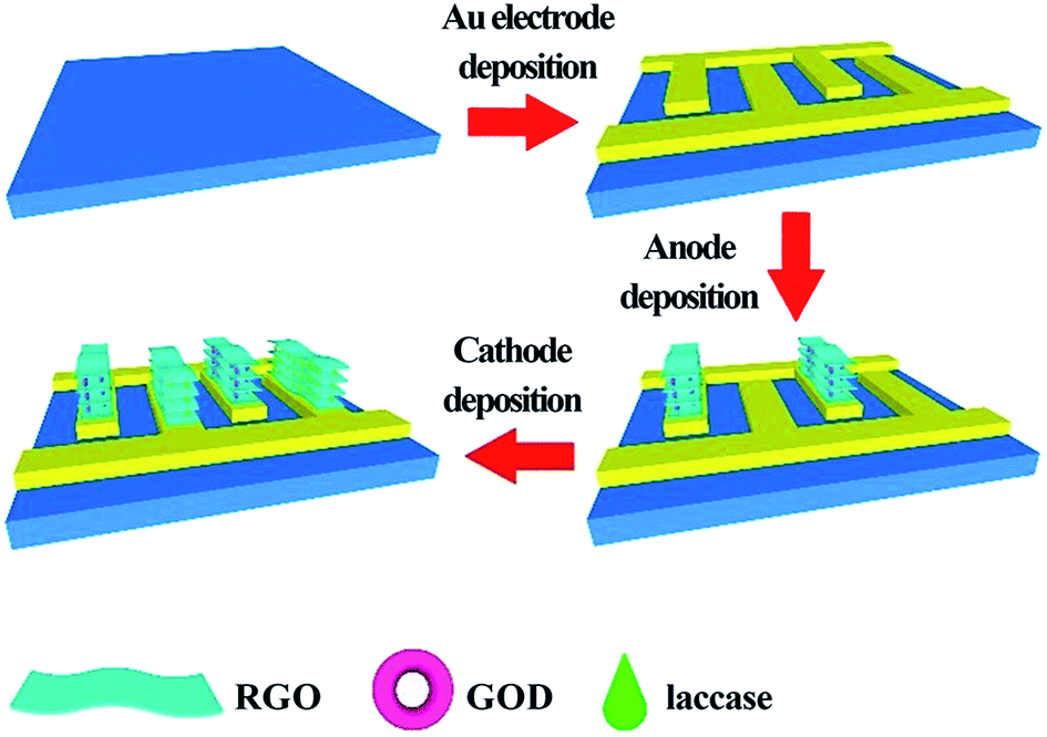 | ||
| Fig. 4 Schematic of the fabrication process of on-chip, mediator- and membrane-less micro-glucose biofuel cells based on the LbL assembly with RGO-enzyme hybrids. Reprinted with permission from ref. 89, copyright 2018, General Chemistry. | ||
At present, carbon nanomaterials seem to be the most appropriate electrical host matrix in biofuel cells due to their highly specific surface, high conductivity and biocompatibility. CNTs and graphene can establish an efficient electron transfer pathway between the electrode and the active site of the enzymes, and facilitate the immobilization of enzymes. Nevertheless, other carbon-based nanostructures such as carbon nanodots8 also show its strong applicability and wide application prospects in LbL assembly-based EBFCs.
3.2. Polyelectrolytes
According to Decher's research, the commonest approach of the LbL assembly is consecutively immersing a solid support into solutions containing oppositely charged polyelectrolytes to form structures based on the electrostatic attraction between polyelectrolytes.39 Therefore, polyelectrolytes can be used as coating materials for the LbL assembly-based electrode, which can achieve the adsorption with enzymes by the electrostatic interaction. Polycations mainly used in the electrode include: poly(ethyleneimine) (PEI), poly-L-lysine (PLL), poly(dimethyldiallylammonium chloride) (PDDA), polyaniline (PANI) and chitosan (CS). Commonly used polyanions are poly(styrenesulfonate) (PSS), poly(vinylsulfonate) (PVS), poly(acrylic acid) (PAA) and DNA.90Hyun et al. demonstrated a high-performance EBFC with the [GOx/PEI]n/CNT layer.71 The EBFC was fabricated with GOx as the anode biocatalyst for the oxidation of glucose, with flavin adenine dinucleotides (FADs) as the cofactors, and platinum as the cathode catalyst for O2 reduction. FADs located inside GOx played an important role because the cofactors are the main place to complete the redox reaction where two electrons and two protons are transferred. At the surface of the bioanode, the [GOx/PEI]n/CNT layer was formed by depositing positively charged PEI and negatively charged GOx on MWCNTs. The GOx content could be controlled easily by adjusting the number of layers, and the PEI layer could provide opposite charges to reduce the electrostatic repulsion between each GOx layer. Fig. 5A represents the formation principle of the [GOx/PEI]n/CNT layer, and the inset shows the polarization curves of EBFCs adopting the [GOx/PEI]n/CNT layer (n = 1, 2 and 3). The formation of the multilayer structure was monitored by measuring ζ-potentials and XPS spectra. Moreover, it was important to determine the GOx/PEI layer that showed optimal catalytic activity. The optimal number of multilayer structure was determined by the measurement of CV curves. As for EBFC, its polarization curves are measured to gain maximum power density. For this test, the GOx/PEI layer was repeatedly used to build the multilayer structure. The maximum power density of EBFC adopting [GOx/PEI]1/CNT was 1.11 mW cm−2. When the GOx/PEI layer number was 2, the maximum power density of EBFC was 1.34 mW cm−2. Furthermore, the maximum power density of EBFC adopting [GOx/PEI]3/CNT was 1.22 mW cm−2. It can be explained that the structure of [GOx/PEI]n/CNT layer could load more enzymes and sensitive materials than a single layer, while the excessive number of layers could hinder the transfer of electrons as well. As a comparison, the maximum power density of EBFC adopting the polymerized GOx/PANI structure with a 1,4-benzoquinone mediator was 0.31 mW cm−2.91 In addition, the EBFC with a [GOx/PEI]2/CNT layer maintained ∼83% of its initial activity even after two weeks. Deng and his partners designed a biocathode with the multilayer film of laccases, PLL and MWCNTs.83 The laccase immobilized by the LbL assembly exhibited a high-performance catalysis of the reduction of O2. In order to obtain a stable multilayer film structure, a layer of branched-poly (ethylenimine) (B-PEI) was first fixed on the indium-doped tin oxide (ITO) electrode, whose surface was negatively charged after cleaning with NaOH and ethanol. Then, the [MWCNTs/PLL/laccase]n multilayer was prepared by sequentially immersing the electrode into the MWCNT solution, PLL aqueous solution and laccase aqueous solution. The assembly process is shown in Fig. 5B. The experiment showed that the performance of EBFC increased with the increase in the number of layers. When the layer number was 15, the open circuit voltage reached 700 mV and the power density was 329 μW cm−2 at 470 mV. In general, when the multilayer structure is prepared by immersion, the optimized concentration of the polyelectrolyte solution is about 1–3 mg mL−1. For instance, the PEI solution was used at a concentration of 2.5 mg mL−1. In addition, it would take 15 to 20 minutes to fix each layer in order to obtain a stable multilayer structure.
 | ||
| Fig. 5 Schematic showing: (A) Fabrication of the [GOx/PEI]n/CNT layer (inset shows polarization curves of EBFCs adopting the [GOx/PEI]n/CNT layers). Reprinted with permission from ref. 71, copyright 2015, Elsevier. (B) Fabrication of the [MWCNTs/PLL/laccase]n layer. Reprinted with permission from ref. 83, copyright 2008, Elsevier. | ||
Better stability was achieved via a unique combination of the LbL assembly together with cross-linking. The addition of the glutaraldehyde (GA) cross-linking required 1 to 2 hours for incubation. Christwardana and Kwon combined the LbL assembly and GA crosslinking for immobilizing enzymes. They produced a high-stability EBFC with GOx-based bioanode.74 In this study, the [GOx/PANI/CNT]n layer was fabricated by the LbL deposition of PANI and GOx on CNTs. GA (0.5 w/v%) as the cross-linker can form strong covalent bonds by the aldol condensation reaction for improving the stability (Fig. 6A). The maximum power density of EBFC with the structure of GA/[GOx/PANI/CNT]3 layers lost only 7% of its initial value after four weeks. After that, Christwardana and coworkers modified both the bioanode and biocathode by the LbL assembly (Fig. 6B).92 The PEI, GA and CNT were used as the conducting polymer, cross-linker and supporter, respectively. As the catalysts, GOx and laccase were immobilized in the multilayer structure with a high loading for improving the power output of EBFC. The maximum power density was 171 μW cm−2 with the structures of GA/[[GOx/PEI]2/CNT] layers as the anode and GA [laccase/PEI/laccase/CNT] layers as the cathode.
 | ||
| Fig. 6 Schematic showing: (A) Fabrication of the GA/[GOx/PANI/CNTs]n layer. Reprinted with permission from ref. 74, copyright 2015, Elsevier. (B)Structures of GA/[[GOx/PEI]2/CNTs] as bioanodes, and GA [laccase/PEI/laccase/CNTs] as biocathodes. Reprinted with permission from ref. 92, copyright 2016, Springer Nature Limited. | ||
Besides glucose, Zhang et al. developed sucrose as the fuel with the bi-enzyme of invertase (INV)/glucose dehydrogenase (GDH) by the LbL assembly.85 In order to speed up the transmission of electrons, [Ni(phendion)(phen)]Cl2 complex was used as a redox mediator on the surface of the electrode. During the formation of this electrode, CNTs were first used to fix the biomolecule to prepare the corresponding layer structure, and the layers contain: CNT-PEI, CNT-DNA and CNT-enzymes (INV or GDH). Then, each layer was modified onto the electrode surface sequentially, as described in Fig. 7. The efficiency of the enzyme cascade improved because of the high permeability of the multilayer structure. The maximum power density obtained in this study was 405 μW cm−2, which showed superior performance over other disaccharide biofuel cells.93
 | ||
| Fig. 7 Schematic of an LbL-assembled bioanode for catalyzing the oxidation of sucrose in an EBFC. Reprinted with permission from ref. 85, copyright 2016, The Electrochemical Society. | ||
As the commonest coating materials, polyelectrolytes have been used in LbL assembly-based EBFCs for decades since the LbL assembly was first proposed. The charged polyelectrolytes can be assembled with carbon nanotubes, enzymes or metal nanoparticles, which offer a high level of freedom in the construction of multilayer membrane structures. There is no doubt that polyelectrolytes play a key role in the development of LbL assembly-based EBFCs.
3.3. Metal nanoparticles
Metal nanoparticles have found numerous applications in biomedical research.94 In EBFCs, metal nanoparticles have been demonstrated to constitute useful interfaces for the electrocatalysis of redox processes of molecules such as H2O2 or O2.95 Metal nanoparticles have been reported because of their large surface area, and high potential in catalytic applications. Without taking into account that they are electrocatalysts, metal nanoparticles represented a flexible way to immobilize enzymes at electrodes while sometimes achieving DET.96 Gold, silver and platinum nanoparticles were deeply investigated in EBFCs due to their positively charged property to form a multilayer structure with opposite-charged enzymes.Deng et al. described an EBFC based on a 3D ordered macroporous (3DOM) gold electrode with the LbL assembly technique.84 The Au nanoparticles (AuNPs) were chosen to modify the 3DOM gold electrode and immobilize enzymes, GDH or laccases. The structure of EBFCs with GDH as the anode biocatalyst, NADH as the cofactor for the oxidation of glucose and laccase as the cathode biocatalyst for O2 reduction is shown in Fig. 8A. In this multilayer structure, the AuNP-modified 3DOM gold electrode provided an effective electronic transfer pathway and a biocompatible environment for enzymes. The maximum power density of EBFC with the [AuNPs/enzyme]5-modified bioelectrode was 178 μW cm−2 at 226 mV, and the open circuit voltage was 320 mV. The power density of the EBFC used in the 3DOM electrode was 16 times as high as that of the EBFC used in the flat electrode. In addition, a novel electrode structure of CNTs coated with poly (amidoamine)dendrimer-encapsulated platinum nanoparticles (Pt-DENs) and GOx was investigated through an LbL assembly and crosslinking approach.97 The layer of Pt-DENs had good biocompatibility and adequate functional groups, both beneficial to modify the electrode surface. The Pt-DENs/CNTs heterostructures were covalently coupled by 1-ethyl-3-[3-(dimethylamino)propyl] carbodiimide (EDC), which could link Pt-DENs and CNTs. Then the GOx/Pt-DENs/CNTs hybrid was gained by mixing the Pt-DENs/CNTs nanocomposites with the GOx solution. Finally, the [GOx/Pt-DENs]n/CNTs suspension was added dropwise onto the carbon paper electrode (Fig. 8B). The accurate layer control might enhance the performance of miniaturized biofuel cells. The open circuit voltage of [GOx/Pt-DENs]n/CNTs-based EBFCs was 640 mV. The advantages of metal nanoparticles in LbL assembly-based EBFC applications are their high conductivity and electrocatalysis. Therefore, the preparation of metal nanoparticles is critical for the development of EBFCs.
 | ||
| Fig. 8 Schematic showing: (A) Fabrication of the [AuNPs/enzyme]n films. Reprinted with permission from ref. 84, copyright 2008, Elsevier. (B) Enzymatic biofuel cell using [GOx/Pt-DENs]n/CNT as anode. Reprinted with permission from ref. 97, copyright 2012, Elsevier. | ||
3.4. Small molecule
Although carbon nanomaterials, polyelectrolytes, and metal nanomaterials are widely used in LbL assembly-based EBFCs, researchers are still exploring new suitable materials. A recent study showed that the small-molecule linker-induced LbL assembly was superior to bulky polymers in EBFCs. Scientists suggested that bulky polymers would increase the contact resistance and suppress the electron transfer.98 Kown et al. demonstrated a high-power EBFC by using small-molecule-linker-derived metal nanoparticles and enzyme multilayers.99 A highly porous metallic cotton fiber (MCF) was applied in the EBFCs, which consisted of cotton fibers, PEI, tetraoctylammonium bromide-stabilized AuNPs (TOA-AuNPs) and tris-(2-aminoethyl)amine (TREN) (Fig. 9A). TREN is an amine-functionalized small molecule that could interact covalently with AuNPs and electrostatically with GOx, thereby improving the stability of the MCF-based EBFC. At the anode, glucose was oxidized to gluconolactone, where the electrons were transferred from GOx to MCF. At the cathode, electrons were transferred in the opposite direction with the oxygen reduction reaction (ORR), as shown in Fig. 9B. The EBFC exhibited a remarkable power density of 3.7 mW cm−2, which was significantly better than conventional biofuel cells. Although there are not many applications of small molecules on LbL assembled-based EBFC, the prospects would be extremely extensive. | ||
| Fig. 9 Schematic of the MCF electrode-based biofuel cell. (A) Preparation of MCF-based cathode and GOx/MCF-based anode using a small-molecule ligand-induced LbL assembly. At the first stage, a bare cotton fiber was coated with PEI. (B) Redox process for an MCF-biofuel cell (BFC) composed of a cathode and an anode. Reprinted with permission from ref. 99, copyright 2018, Springer Nature Limited. | ||
The development of electrode modification processes supported that multiple coating materials were used in EBFCs.16 The evolution of nanotechnology has brought significant advances in the electrode modification of EBFCs.100 The preparation of bioelectrodes from the nanoscale level can maintain the catalytic activity of the enzyme well. The crucial parameters of some applications are listed in Table 1. The power density of EBFC is an important parameter that is obtained by the real power generated by EBFC in order to determine which applications can actually be supported.101 Because more suitable materials were used to modify the bioelectrode, the power density of EBFC increased by several orders of magnitude. In the latest applications, the power density has reached mW cm−2 (or mW cm−3). Compared with other EBFCs in the same period, LbL assembly-based EBFCs have simpler operation and better performance. In the future, some new coating materials and appropriate multilayer structure can be investigated to improve the performance of LbL assembled-based EBFCs.
| System | Number of layers | Electrode | Fuel (conc.) | Enzyme | OCVa (mV) | MPDb (μW cm−2) | Stability | Ref. |
|---|---|---|---|---|---|---|---|---|
| a Open circuit voltage. b Maximum power density. | ||||||||
| Cathode: [MWCNTs/PLL/laccase]15 | 15 | ITO electrode | Glucose (30 mM) | Laccase | 700 | 329 | 70% after 1 week | 83 |
| Anode: [AuNPs/GDH]5 | 5 | 3DOM gold electrode | Glucose (30 mM) | GDH/laccase | 320 | 178 | — | 84 |
| Cathode: [AuNPs/laccase]5 | 5 | |||||||
| Anode: [GOx/Pt-DENs]3/CNTs | 3 | Carbon paper | Glucose (20 mM) | GOx | 640 | 17 | — | 97 |
| Anode: [GOx/PANI/CNT]3/GA | 3 | Carbon paper | Glucose (30 mM) | GOx | — | 290 | 93% after 4 weeks | 74 |
| Anode: [GOx/PEI]2/CNT | 2 | Carbon fiber | Glucose (400 mM) | GOx | — | 1340 | 83% after 2 weeks | 71 |
| Anode: GA/[[GOx/PEI]2/CNT] | 2 | Carbon paper | Glucose (40 mM) | GOx/laccase | — | 171 | 77% after 4 weeks | 92 |
| Cathode: GA/[laccase/PEI/laccase/CNT] | 2 | |||||||
| Anode: [MWCNTs-PEI/DNA/PEI/GDH/PEI/INV] | 6 | GC electrode | Sucrose (200 mM) | INV/GDH | 604 | 405 | — | 85 |
| Anode: [TREN/GOx]/MCF | 30 | MCF | Glucose (30 mM) | GOx | — | 3700 | 79% after 5 weeks | 99 |
| Cathode: [TREN/TOA-AuNPs]/PEI/cotton fiber | 120 | |||||||
| Anode: [RGO/GOx] | — | Au electrode | Glucose (50 mM) | GOx/laccase | 128 | 14![[thin space (1/6-em)]](https://www.rsc.org/images/entities/char_2009.gif) 770 (μW cm−3) 770 (μW cm−3) |
— | 89 |
| Cathode: [RGO/laccase] | ||||||||
4. Summary and outlook
The low power density, slow electron transfer and short-term stability are the critical factors that limit the application of EBFCs. Thus, scientists have made great efforts to overcome these problems. Moreover, the technologies of immobilizing enzymes for improving the performance of EBFCs have attracted people's attention. In this paper, an LbL assembly method for immobilizing enzymes on the electrode of EBFCs was reviewed in detail. Compared with other immobilization methods, the LbL assembly can achieve controllable immobilization of enzymes by building a multilayer structure with easy operation.In addition, in order to further improve the power output and lifetime of EBFCs, nanomaterials are modified on the surface of electrodes by the LbL assembly technology. For example, due to their close proximity to the active site of the enzyme, CNTs can accelerate the electron transfer rate between the enzyme activity center and the electrode by establishing an effective electron transfer pathway. Combining with LbL assembly technology, graphene also enhances the power density of EBFCs because of its 2D structure and excellent electrochemical stability. Beyond that, the combination of LbL assembly technology and some polyelectrolyte materials, metal nanomaterials or small molecules show better prospects in EBFCs.
Despite easy operation of the LbL assembly, EBFCs based on this technology are still not common. The main bottleneck is that researchers expend considerable efforts to build a stable multilayer structure of sensitive materials. Nevertheless, the mechanism of LbL assembly is clear, which can provide valuable suggestions for material selection and assembly strategy. Therefore, this immobilization technology holds promising prospects for the EBFC applications in the future.
Conflicts of interest
We declare that we do not have any commercial or associative interest that represents a conflict of interest in connection with the work submitted.Acknowledgements
This work was supported by the National Natural Science Foundation of China (61801256, U1806202), Shandong Province Key Research and Development Plan (2018GGX109016), Shandong Natural Science Foundation (ZR2018ZC0129, ZR2019MEE051) and Beijing Natural Science Foundation (4182075).References
- S. Zhong and Q. Xu, Bull. Chem. Soc. Jpn., 2018, 91, 1606–1617 CrossRef CAS.
- Z. Wang, C. Li and K. Domen, Chem. Soc. Rev., 2019, 48, 219–2125 Search PubMed.
- H. Kobayashi and A. Fukuoka, Bull. Chem. Soc. Jpn., 2018, 91, 29–43 CrossRef CAS.
- Y. Wang, H. Suzuki, J. Xie, O. Tomita, D. J. Martin, M. Higashi, D. Kong, R. Abe and J. Tang, Chem. Rev., 2018, 118, 5201–5241 CrossRef CAS PubMed.
- Y. Wu, X. Zhang, S. Li, X. Lv, Y. Cheng and X. Wang, Electrochim. Acta, 2013, 109, 328–332 CrossRef CAS.
- S. Cosnier, A. J. Gross, F. Giroud and M. Holzinger, Curr. Opin. Electrochem., 2018, 12, 148–155 CrossRef CAS.
- R. L. Arechederra, K. Boehm and S. D. Minteer, Electrochim. Acta, 2009, 54, 7268–7273 CrossRef CAS.
- X. Huang, L. Zhang, Z. Zhang, S. Guo, H. Shang, Y. Li and J. Liu, Biosens. Bioelectron., 2019, 124–125, 40–52 CrossRef CAS PubMed.
- A. T. Yahiro, S. M. Lee and D. O. Kimble, Biochim. Biophys. Acta, 1964, 88, 375–383 CAS.
- N. Mano and L. Edembe, Biosens. Bioelectron., 2013, 50, 478–485 CrossRef CAS PubMed.
- M. Rasmussen, S. Abdellaoui and S. D. Minteer, Biosens. Bioelectron., 2016, 76, 91–102 CrossRef CAS PubMed.
- E. V. Plotkin, I. J. Higgins and H. A. O. Hill, Biotechnol. Lett., 1981, 3, 187–192 CrossRef CAS.
- B. Persson, L. Gorton, G. Johansson and A. Torstensson, Enzyme Microb. Technol., 1985, 7, 549–552 CrossRef CAS.
- D. Wen and A. Eychmüller, Small, 2016, 12, 4649–4661 CrossRef CAS PubMed.
- M. Falk, C. W. Narváez Villarrubia, S. Babanova, P. Atanassov and S. Shleev, ChemPhysChem, 2013, 14, 2045–2058 CrossRef CAS PubMed.
- P. Pinyou, V. Blay, L. M. Muresan and T. Noguer, Mater. Horiz., 2019, 6, 1336–1358 RSC.
- H. Y. Zhao, H. M. Zhou, J. X. Zhang, W. Zheng and Y. F. Zheng, Biosens. Bioelectron., 2009, 25, 463–468 CrossRef CAS PubMed.
- Y. Tan, W. Deng, B. Ge, Q. Xie, J. Huang and S. Yao, Biosens. Bioelectron., 2009, 24, 2225–2231 CrossRef CAS PubMed.
- T. Garcia-Perez, S. Hong, J. Kim and S. Ha, Enzyme Microb. Technol., 2016, 90, 26–34 CrossRef CAS PubMed.
- Y. Tan, W. Deng, Y. Li, Z. Huang, Y. Meng, Q. Xie, M. Ma and S. Yao, J. Phys. Chem. B, 2010, 114, 5016–5024 CrossRef CAS PubMed.
- A. H. Suroviec, in Enzyme Stabilization and Immobilization, ed. S. D. Minteer, Springer Science+Business Media LLC, New York, 2017, vol. 16, pp. 203–213 Search PubMed.
- I. Díaz, R. M. Blanco, M. Sánchez-Sánchez and C. Márquez-Álvarez, in Zeolites and Metal-Organic Frameworks. From lab to industry, ed. V. Blay, A. Cabrera-García and L. Bobadilla, Amsterdam University Press, 2018, pp. 149–174 Search PubMed.
- K. Y. Kwon, J. Youn, J. H. Kim, Y. Park, C. Jeon, B. C. Kim, Y. Kwon, X. Zhao, P. Wang and B. I. Sang, Biosens. Bioelectron., 2010, 26, 655–660 CrossRef CAS PubMed.
- C. Liu, S. Alwarappan, Z. Chen, X. Kong and C. Li, Biosens. Bioelectron., 2010, 25, 1829–1833 CrossRef CAS PubMed.
- J. Liu, L. Zhang and C. Fu, Anal. Methods, 2015, 7, 6158–6164 RSC.
- G. Decher and J. B. Schlenoff, Multilayer Thin Films: Sequential Assembly of Nanocomposite Materials, Wiley-VCH Verlag GmbH & Co. KGaA, Weinheim, Germany, 2012 Search PubMed.
- K. Ariga, E. Ahn, M. Park and B. S. Kim, Chem.–Asian J., 2019, 14, 2553–2566 CrossRef CAS PubMed.
- J. L. Lutkenhaus and P. T. Hammond, Soft Matter, 2007, 3, 804–816 RSC.
- H. Ai, S. A. Jones and Y. M. Lvov, Cell Biochem. Biophys., 2003, 39, 23–43 CrossRef CAS PubMed.
- E. A. Appel, M. W. Tibbitt, J. M. Greer, O. S. Fenton, K. Kreuels, D. G. Anderson and R. Langer, ACS Macro Lett., 2015, 4, 848–852 CrossRef CAS.
- E. Kharlampieva, V. Kozlovskaya, J. Tyutina and S. A. Sukhishvili, Macromolecules, 2005, 38, 10523–10531 CrossRef CAS.
- S. Amigoni, E. Taffin De Givenchy, M. Dufay and F. Guittard, Langmuir, 2009, 25, 11073–11077 CrossRef CAS PubMed.
- P. Wei, X. Yan and F. Huang, Chem. Soc. Rev., 2015, 44, 815–832 RSC.
- G. N. Calaça, C. A. Erdmann, A. L. Soares, C. A. Pessôa, S. T. Fujiwara, J. R. Garcia, M. Vidotti and K. Wohnrath, Electrochim. Acta, 2017, 249, 104–112 CrossRef.
- F. Lisdat, Curr. Opin. Electrochem., 2017, 5, 165–172 CrossRef CAS.
- Z. Tang, Y. Wang, P. Podsiadlo and N. A. Kotov, Adv. Mater., 2006, 18, 3203–3224 CrossRef CAS.
- G. G. Roberts and C. W. Pitt, Langmuir-Blodgett Films, Proceedings of the First International Conference on Langmuir-Blodgett Films, Elsevier Scientific Pub. Co., Britain, 1982 Search PubMed.
- R. K. Iler, J. Colloid Interface Sci., 1966, 21, 569–594 CrossRef CAS.
- G. Decher, Science, 1997, 277, 1232–1237 CrossRef CAS.
- G. Decher, M. Eckle, J. Schmitt and B. Struth, Curr. Opin. Colloid Interface Sci., 1998, 3, 32–39 CrossRef CAS.
- G. Decher, J. D. Hong and J. Schmitt, Thin Solid Films, 1992, 210, 831–835 CrossRef.
- G. Decher and J. D. Hong, Makromol. Chem., Macromol. Symp., 1991, 46, 321–327 CrossRef CAS.
- G. Decher and J. D. Hong, Ber. Bunsenges. Phys. Chem, 1991, 95, 1430–1434 CrossRef CAS.
- P. Bertrand, A. Jonas, A. Laschewsky and R. Legras, Macromol. Rapid Commun., 2000, 21, 319–348 CrossRef CAS.
- F. Caruso, E. Donath and H. Mohwald, J. Phys. Chem. B, 1998, 102, 2011–2016 CrossRef CAS.
- G. Ladam, P. Schaad, J. C. Voegel, P. Schaaf, G. Decher and F. Cuisinier, Langmuir, 2000, 16, 1249–1255 CrossRef CAS.
- G. Rydzek, Q. Ji, M. Li, P. Schaaf, J. P. Hill, F. Boulmedais and K. Ariga, Nano Today, 2015, 10, 138–167 CrossRef CAS.
- D. M. Guldi and M. Prato, Chem. Commun., 2004, 2517–2525 RSC.
- E. Donath, G. B. Sukhorukov, F. Caruso, S. A. Davis and H. Mohwald, Angew. Chem., Int. Ed., 1998, 37, 2201–2205 CrossRef PubMed.
- Y. Lvov, K. Ariga, I. Ichinose and T. Kunitake, J. Am. Chem. Soc., 1995, 117, 6117–6123 CrossRef CAS.
- J. Zhuang, M. Garzoni, D. A. Torres, A. Poe, G. M. Pavan and S. Thayumanavan, Angew. Chem. Int. Ed., 2017, 56, 4145–4149 CrossRef CAS PubMed.
- G. Rydzek, Q. Ji, M. Li, P. Schaaf, J. P. Hill, F. Boulmedais and K. Ariga, Nano Today, 2015, 10, 138–167 CrossRef CAS.
- J. Wang, X. Zhao, J. Li, X. Kuang, Y. Fan, G. Wei and Z. Su, ACS Macro Lett., 2014, 3, 529–533 CrossRef CAS.
- W. B. Stockton and M. F. Rubner, Macromolecules, 1997, 30, 2717–2725 CrossRef CAS.
- B. Kim, S. W. Park and P. T. Hammond, ACS Nano, 2008, 2, 386–392 CrossRef CAS PubMed.
- Y. Fu, S. Bai, S. Cui, D. Qiu, Z. Wang and X. Zhang, Macromolecules, 2002, 35, 9451–9458 CrossRef CAS.
- S. S. Ono and G. Decher, Nano Lett., 2006, 6, 592–598 CrossRef CAS PubMed.
- I. Erel-Unal and S. A. Sukhishvili, Macromolecules, 2008, 41, 8737–8744 CrossRef CAS.
- Y. Zhang, H. He, C. Gao and J. Wu, Langmuir, 2009, 25, 5814–5824 CrossRef CAS PubMed.
- M. Ramanathan, I. S. Michael Kilbey, Q. Ji, J. Hill and K. Ariga, J. Mater. Chem., 2012, 22, 10389–10405 RSC.
- H. Hu, C. R. Weinberger and Y. Sun, J. Phys. Chem. C, 2015, 119, 11777–11785 CrossRef CAS.
- N. Joseph, P. Ahmadiannamini, R. Hoogenboom and I. F. J. Vankelecom, Polym. Chem., 2014, 5, 1817–1831 RSC.
- S. De Koker, R. Hoogenboom and B. G. De Geest, Chem. Soc. Rev., 2012, 41, 2867–2884 RSC.
- D. Kim, M. Gu, M. Park, T. Kim and B. Kim, Mol. Syst. Des. Eng., 2019, 4, 65–77 RSC.
- W. Wu, H. Niu, D. Yang, S. Wang, N. Jiang, J. Wang, J. Lin and C. Hu, Polymers, 2018, 10, 759 CrossRef PubMed.
- M. Onda, Y. Lvov, K. Ariga and T. Kunitake, Biotechnol. Bioeng., 1996, 51, 163–167 CrossRef PubMed.
- M. Onda, Y. Lvov, K. Ariga and T. Kunitake, J. Ferment. Bioeng., 1996, 82, 502–506 CrossRef CAS.
- S. V. Rao, K. W. Anderson and L. G. Bachas, Biotechnol. Bioeng., 1999, 65, 389–396 CrossRef CAS PubMed.
- S. H. Kim, J. P.K. Tan, F. Nederberg, K. Fukushima, J. Colson, C. Yang, A. Nelson, Y. Yang and J. L. Hedrick, Biomaterials, 2010, 31, 8063–8071 CrossRef CAS PubMed.
- M. M. de Villiers, D. P. Otto, S. J. Strydom and Y. M. Lvov, Adv. Drug Deliv. Rev., 2011, 63, 701–715 CrossRef CAS PubMed.
- K. H. Hyun, S. W. Han, W. Koh and Y. Kwon, J. Power Sources, 2015, 286, 197–203 CrossRef CAS.
- W. Zhao, J. Xu and H. Chen, Electroanalytical, 2006, 18, 1737–1748 CrossRef CAS.
- P. Gai, Y. Ji, Y. Chen, C. Zhu, J. Zhang and J. Zhu, Analyst, 2015, 140, 1822–1826 RSC.
- M. Christwardana and Y. Kwon, J. Power Sources, 2015, 299, 604–610 CrossRef CAS.
- R. Perveen, Inamuddin, A. Nasar, Beenish and A. M. Asiri, Int. J. Biol. Macromol., 2018, 106, 755–762 CrossRef CAS PubMed.
- E. S. Forzani, M. L. Teijelo, F. Nart, E. J. Calvo and V. M. Solís, Biomacromolecules, 2003, 4, 869–879 CrossRef CAS PubMed.
- A. Mugweru, B. Wang and J. Rusling, Anal. Chem., 2004, 76, 5557–5563 CrossRef CAS PubMed.
- S. Nilsson, F. Björefors and N. D. Robinson, Appl. Surf. Sci., 2013, 280, 783–790 CrossRef CAS.
- S. Iijima, Nature, 1991, 354, 56–58 CrossRef CAS.
- J. Qiu, W. Zhou, J. Guo, R. Wang and R. Liang, Anal. Biochem., 2009, 385, 264–269 CrossRef CAS PubMed.
- J. Liu, S. Sun, H. Shang, J. Lai and L. Zhang, Electroanalysis, 2016, 28, 2016–2021 CrossRef CAS.
- L. Deng, C. Chen, M. Zhou, S. Guo, E. Wang and S. Dong, Anal. Chem., 2010, 82, 4283–4287 CrossRef CAS PubMed.
- L. Deng, L. Shang, Y. Wang, T. Wang, H. Chen and S. Dong, Electrochem. Commun., 2008, 10, 1012–1015 CrossRef CAS.
- L. Deng, F. Wang, H. Chen, L. Shang, L. Wang, T. Wang and S. Dong, Biosens. Bioelectron., 2008, 24, 329–333 CrossRef CAS PubMed.
- Y. Zhang, M. A. Arugula, S. T. Williams, S. D. Minteer and A. L. Simonian, J. Electrochem. Soc., 2016, 163, F449–F454 CrossRef CAS.
- M. F. El-Kady, V. Strong, S. Dubin and R. B. Kaner, Science, 2012, 335, 1326–1330 CrossRef CAS PubMed.
- R. Xiong, K. Hu, A. M. Grant, R. Ma, W. Xu, C. Lu, X. Zhang and V. V. Tsukruk, Adv. Mater., 2016, 28, 1501–1509 CrossRef CAS PubMed.
- H. Zhang, L. Zhang, Y. Han, Y. Yu, M. Xu, X. Zhang, L. Huang and S. Dong, Biosens. Bioelectron., 2017, 97, 34–40 CrossRef CAS PubMed.
- M. Wang, Q. Tao, B. Liu, C. Li, L. Chen, C. Yan, M. Wang, Q. Tao, B. Liu, C. Li, L. Chen and C. Yan, General Chemistry, 2018, 4, 20180001 Search PubMed.
- M. Campàs and C. O'Sullivan, Anal. Lett., 2003, 36, 2551–2569 CrossRef.
- H. Kim, I. Lee, Y. Kwon, B. C. Kim, S. Ha, J. Lee and J. Kim, Biosens. Bioelectron., 2011, 26, 3908–3913 CrossRef CAS PubMed.
- M. Christwardana, K. J. Kim and Y. Kwon, Sci. Rep., 2016, 6, 30128 CrossRef CAS PubMed.
- D. P. Hickey, F. Giroud, D. W. Schmidtke, D. T. Glatzhofer and S. D. Minteer, ACS Catal., 2013, 3, 2729–2737 CrossRef CAS.
- A. A. Saei, J. E. N. Dolatabadi, P. Najafi-Marandi, A. Abhari and M. de la Guardia, Trends Anal. Chem., 2013, 42, 216–227 CrossRef CAS.
- M. H. Rashid, R. R. Bhattacharjee, A. Kotal and T. K. Mandal, Langmuir, 2006, 22, 7141–7143 CrossRef CAS PubMed.
- F. N. Crespilho, in Nanobioelectrochemistry: From Implantable Biosensors to Green Power Generation, ed. F. N. Crespilho, Springer-Verlag, Berlin, Heidelberg, 2013, vol. 3, pp. 49–66 Search PubMed.
- J. Zhang, Y. Zhu, C. Chen, X. Yang and C. Li, Particuology, 2012, 10, 450–455 CrossRef CAS.
- H. Zhao and H. Ju, Anal. Biochem., 2006, 350, 138–144 CrossRef CAS PubMed.
- C. H. Kwon, Y. Ko, D. Shin, M. Kwon, J. Park, W. K. Bae, S. W. Lee and J. Cho, Nat. Commun., 2018, 9, 4779 CrossRef PubMed.
- C. E. Zhao, P. Gai, R. Song, Y. Chen, J. Zhang and J. J. Zhu, Chem. Soc. Rev., 2017, 46, 1545–1564 RSC.
- M. Gamella, A. Koushanpour and E. Katz, Bioelectrochemistry, 2018, 119, 33–42 CrossRef CAS PubMed.
| This journal is © The Royal Society of Chemistry 2020 |