 Open Access Article
Creative Commons Attribution 3.0 Unported Licence
Correction: Helical orbitals and circular currents in linear carbon wires
Marc H.
Garner
 *,
Anders
Jensen
,
Louise O. H.
Hyllested
and
Gemma C.
Solomon
 *
*
Department of Chemistry, Nano-Science Center, University of Copenhagen, Universitetsparken 5, DK-2100, Copenhagen Ø, Denmark. E-mail: marc@chem.ku.dk; gsolomon@chem.ku.dk
First published on 24th February 2020
Abstract
Correction for ‘Helical orbitals and circular currents in linear carbon wires’ by Marc H. Garner et al., Chem. Sci., 2019, 10, 4598–4608.
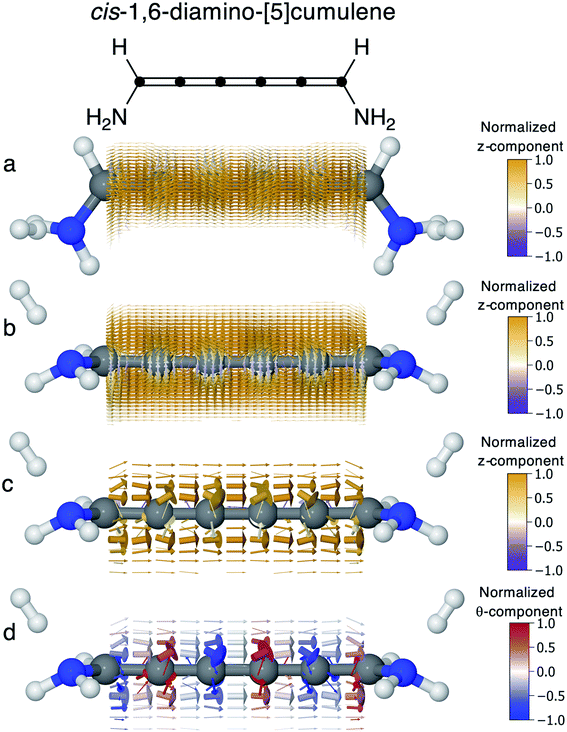
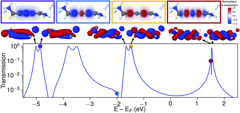
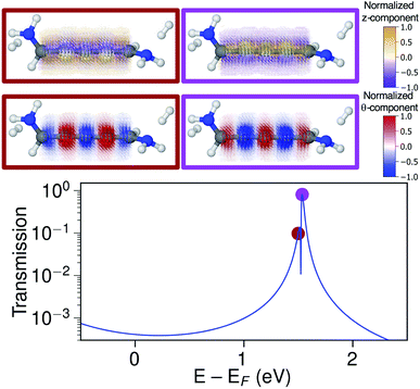
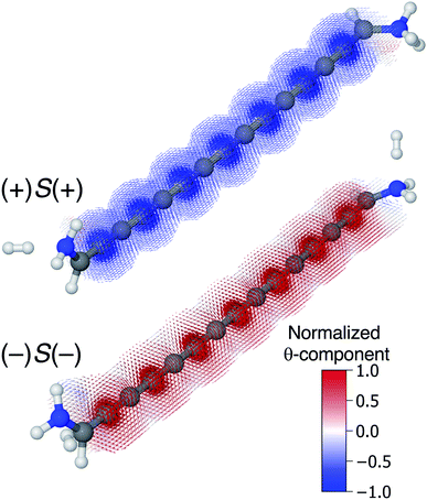
In the original article, a technical error in our homemade code (available at https://github.com/marchgarner/Current_Density) meant that the diameter of the current density arrows was scaled incorrectly. We state in the original paper that the diameter of each arrow is the vector-length (i.e., the magnitude of the current density j in position r). However, it was incorrectly scaled as only the z-component (the transport direction) was considered in the diameter in the originally published figures. This meant that the circular current components were underestimated in the visual presentation, and consequently the circular currents are much clearer and stronger in magnitude than can be deduced from our original presentation.
Here we reproduce all the figures from the original article and ESI material that showed current density plots. The figures are numbered with the same numbers as in the original article. All central conclusions from the original paper remain unchanged, and are in fact further supported by the correct figures, because the circular current components were previously not properly accounted for in the diameter of the current arrows. In cases where the plots primarily have currents in the z direction (for example Fig. 6) the change in the figures is less pronounced.
In the original article, based on Fig. 7, we noted that there is a nodal plane in the current density, as is also seen for the current in normal π systems (e.g. in Fig. 6). However, this is only true for the z-component of the current density, i.e., the forward current as we plotted previously. With the circular components included this nodal plane is not preserved, as can now be seen in Fig. 7.
Given that we scale the current density arrows in each plot by the largest arrow, it is now clear that in many cases the circular currents can be much larger than the net current. This naturally raises the question as to whether a large magnetic field can be achieved from these ring currents even at a low bias. We are working towards assessing this in the near future.
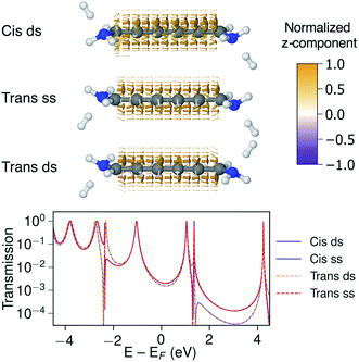 | ||
| Fig. S9 Current density and transmission of 1,6-diamino-[5]cumulene calculated using wide-band electrodes. The cis and trans isomers can have lone-pairs pointing to the same side (ss) or to different sides (ds) of the plane of the cumulene. The current density of Cis-ss is shown in Fig. 6 in the manuscript. | ||
The Royal Society of Chemistry apologises for these errors and any consequent inconvenience to authors and readers.
| This journal is © The Royal Society of Chemistry 2020 |

