
 Open Access Article
 This Open Access Article is licensed under a
 Creative Commons Attribution 3.0 Unported Licence
H2/CO2 separations in multicomponent metal-adeninate MOFs with multiple chemically distinct pore environments†
Zachary M.
Schulte
 a,
Yeon Hye
Kwon
a,
Yi
Han
a,
Chong
Liu
a,
Lin
Li
b,
Yahui
Yang
b,
Austin Gamble
Jarvi
a,
Sunil
Saxena
a,
Götz
Veser
b,
J. Karl
Johnson
b and
Nathaniel L.
Rosi
*abcd
a,
Yeon Hye
Kwon
a,
Yi
Han
a,
Chong
Liu
a,
Lin
Li
b,
Yahui
Yang
b,
Austin Gamble
Jarvi
a,
Sunil
Saxena
a,
Götz
Veser
b,
J. Karl
Johnson
b and
Nathaniel L.
Rosi
*abcd
aDepartment of Chemistry, University of Pittsburgh, Pittsburgh, PA 15260, USA. E-mail: nrosi@pitt.edu
bDepartment of Chemical and Petroleum Engineering, University of Pittsburgh, Pittsburgh, PA 15260, USA
cU.S. Department of Energy, National Energy Technology Laboratory, Pittsburgh, PA 15236, USA
dOak Ridge Institute for Science and Education, Pittsburgh, PA 15236, USA
First published on 15th October 2020
Abstract
Metal–organic frameworks constructed from multiple (≥3) components often exhibit dramatically increased structural complexity compared to their 2 component (1 metal, 1 linker) counterparts, such as multiple chemically unique pore environments and a plurality of diverse molecular diffusion pathways. This inherent complexity can be advantageous for gas separation applications. Here, we report two isoreticular multicomponent MOFs, bMOF-200 (4 components; Cu, Zn, adeninate, pyrazolate) and bMOF-201 (3 components; Zn, adeninate, pyrazolate). We describe their structures, which contain 3 unique interconnected pore environments, and we use Kohn–Sham density functional theory (DFT) along with the climbing image nudged elastic band (CI-NEB) method to predict potential H2/CO2 separation ability of bMOF-200. We examine the H2/CO2 separation performance using both column breakthrough and membrane permeation studies. bMOF-200 membranes exhibit a H2/CO2 separation factor of 7.9. The pore space of bMOF-201 is significantly different than bMOF-200, and one molecular diffusion pathway is occluded by coordinating charge-balancing formate and acetate anions. A consequence of this structural difference is reduced permeability to both H2 and CO2 and a significantly improved H2/CO2 separation factor of 22.2 compared to bMOF-200, which makes bMOF-201 membranes competitive with some of the best performing MOF membranes in terms of H2/CO2 separations.
Introduction
The vast majority of metal–organic frameworks (MOFs) consist of two components: one metal ion/cluster and one organic linker.1–3 In general, such MOFs have uniform pores and channels, and from the point of view of a guest molecule, all the internal space and surfaces, apart from defects, would appear identical. For many target applications,4 such as gas storage5 or catalysis,6 uniform pore space may be ideal. However, MOFs having more complex labyrinths of pores and channels and multiple interior regions with distinct structure and chemical functionality may lead to increasingly complex functions.7,8 For example, different cavities may each contain unique yet complementary reactive centres for multiple reaction steps, or different molecules may diffuse through different pathways, which could lead to improved molecular separations.Achieving increased structural and functional complexity often involves incorporation of multiple components (i.e., metals + linkers ≥ 3) into the MOF material.9,10 These components may be partitioned into specific domains (e.g., core–shell11–15 and stratified MOFs16 or other MOF-on-MOF architectures17–19), or they may be distributed either randomly (e.g., multivariate MOFs20,21) or periodically7,8,22–38 throughout a MOF lattice. Strategies for constructing MOFs with multiple periodically arranged components generally involve syntheses that (i) incorporate multiple linkers having different Lewis basic donor groups (e.g., metal-carboxylate 2-D grids pillared by N-donor linkers22,26,28 or metal-adeninate-carboxylate bio-MOFs24,29); (ii) incorporate multiple linkers of different length and/or geometry having identical donor groups (e.g., MOFs with multiple different carboxylate linkers);7,23,25,27,34,35 (iii) incorporate hetero-multitopic linkers such as (iso)nicotinate that preferentially coordinate different metal ions at either coordination sites;30–33,36 or (iv) use some combination of approaches i–iii (e.g., mixing both pyrazolate and multicarboxylate linkers).8,38 Regardless of the approach, predicting the structural outcome of these syntheses is quite challenging and few examples of explicit structural design exist.33,35,36 Expanding the library of multicomponent MOFs is critical as it allows for identification of structural motifs and patterns that can then be used as input for reticular design.
Our foray into the design and construction of multicomponent MOFs began with exploration of three component metal-adeninate-carboxylate frameworks.24,39 These MOFs exhibit both zinc-adeninate and zinc-carboxylate motifs, providing some evidence that multiple linkers with different Lewis-basic donors could result in distinct structural motifs. Motivated by these findings and those of others,8,30,31 we reasoned that combining two different Lewis basic donor sites onto one ligand may provide a facile means of installing multiple different structural and functional motifs into a MOF, provided that we consider the metal coordination preferences of the different donors. Accordingly, we used isonicotinate as a linker to design and construct MOFs with up to four distinct structural components (three different metal nodes and one linker).36 Here, we build upon these strategies for accessing multicomponent MOFs with multiple different structural motifs and explore the structural space that results from combining adenine with the heterobifunctional linker pyrazolate. Our efforts thus far afforded two isoreticular multicomponent MOFs that exhibit multiple structurally and chemically distinct cavities and numerous possible molecular diffusion pathways. During our development of this work, one of these MOFs was reported by Li and coworkers, who studied its application in ethane/ethylene separations.40 Here, we examine their structures and demonstrate, both computationally and experimentally, how their unusual pore space confers a benefit in terms of H2/CO2 separations compared to various canonical two-component MOF materials. Significantly, we fabricate membranes using these MOFs, we perform membrane permeation studies, and we show that a slight structural difference between the two isoreticular analogues leads to a significant improvement in the H2/CO2 separation factor.
Results and discussion
A solvothermal reaction of adenine, 4-pyrazolecarboxylic acid, and divalent Zn and Cu salts in dimethylformamide (DMF) afforded slightly yellow cubic crystals, which, according to single crystal X-ray diffraction (SC-XRD) studies (see ESI,† Section S7), adopt the cubic space group Fm![[3 with combining macron]](https://www.rsc.org/images/entities/char_0033_0304.gif) c with unit cell dimensions a = b = c = 43.62 Å.† The structure consists of Zn-pyrazolate (Zn-pyz) cages interlinked by Cu-adeninate (Cu-ad) motifs. The Zn-pyz cages are constructed from Zn-pyz dimers (Fig. 1a) in which two tetrahedral Zn(II) are bridged by the N–N linkages of two pyz; the remaining two sites on each Zn(II) are occupied by a monodentate carboxylate from a pyz on a neighbouring Zn-pyz motif and either N1 or N7 from an ad in a neighbouring Cu-ad dimer. Twelve Zn-pyz dimers link together to form the Zn-pyz cages (Fig. 1b). We note that each individual Zn-pyz cage is chiral and alternating cages have opposite chirality, resulting in an achiral crystal. The underlying net of the Zn-pyz cages is perhaps best simplified by treating each Zn-pyz dimer as a single point (purple sphere in Fig. 1c); connecting these points yields a cuboctahedron (Fig. 1c). The Cu-ad motifs consist of two planar Cu2ad2(DMF)2 dimers stacked perpendicular to one another with an interplanar distance of ∼3.4 Å (Fig. 1d and e). Each planar dimer is constructed from two Cu(I) bridged by two ad through N3 and N9; the Cu(I) are terminally coordinated to one DMF. The intercopper distance in each dimer is 2.86 Å, which is within the range of Cu(I)–Cu(I) bonding.24 Each stacked dimer has eight points of extension, two from each ad at N1 and N7. The stacked dimers link four Zn-pyz cages together, with two linkages to each cage. If we simplify each stacked dimer as a 4-connected planar structural motif and connect the corners to the centroid (purple sphere) of the Zn-pyz dimers, the net reduces to ftw-a (Fig. 1f–h).25 The actual net, of course, is more complex, but visualization as ftw-a, we believe, is instructive. We name this material bio-MOF-200 (bMOF-200) and install it as another member of the metal-adeninate bio-MOF series.24,39,41,42
c with unit cell dimensions a = b = c = 43.62 Å.† The structure consists of Zn-pyrazolate (Zn-pyz) cages interlinked by Cu-adeninate (Cu-ad) motifs. The Zn-pyz cages are constructed from Zn-pyz dimers (Fig. 1a) in which two tetrahedral Zn(II) are bridged by the N–N linkages of two pyz; the remaining two sites on each Zn(II) are occupied by a monodentate carboxylate from a pyz on a neighbouring Zn-pyz motif and either N1 or N7 from an ad in a neighbouring Cu-ad dimer. Twelve Zn-pyz dimers link together to form the Zn-pyz cages (Fig. 1b). We note that each individual Zn-pyz cage is chiral and alternating cages have opposite chirality, resulting in an achiral crystal. The underlying net of the Zn-pyz cages is perhaps best simplified by treating each Zn-pyz dimer as a single point (purple sphere in Fig. 1c); connecting these points yields a cuboctahedron (Fig. 1c). The Cu-ad motifs consist of two planar Cu2ad2(DMF)2 dimers stacked perpendicular to one another with an interplanar distance of ∼3.4 Å (Fig. 1d and e). Each planar dimer is constructed from two Cu(I) bridged by two ad through N3 and N9; the Cu(I) are terminally coordinated to one DMF. The intercopper distance in each dimer is 2.86 Å, which is within the range of Cu(I)–Cu(I) bonding.24 Each stacked dimer has eight points of extension, two from each ad at N1 and N7. The stacked dimers link four Zn-pyz cages together, with two linkages to each cage. If we simplify each stacked dimer as a 4-connected planar structural motif and connect the corners to the centroid (purple sphere) of the Zn-pyz dimers, the net reduces to ftw-a (Fig. 1f–h).25 The actual net, of course, is more complex, but visualization as ftw-a, we believe, is instructive. We name this material bio-MOF-200 (bMOF-200) and install it as another member of the metal-adeninate bio-MOF series.24,39,41,42
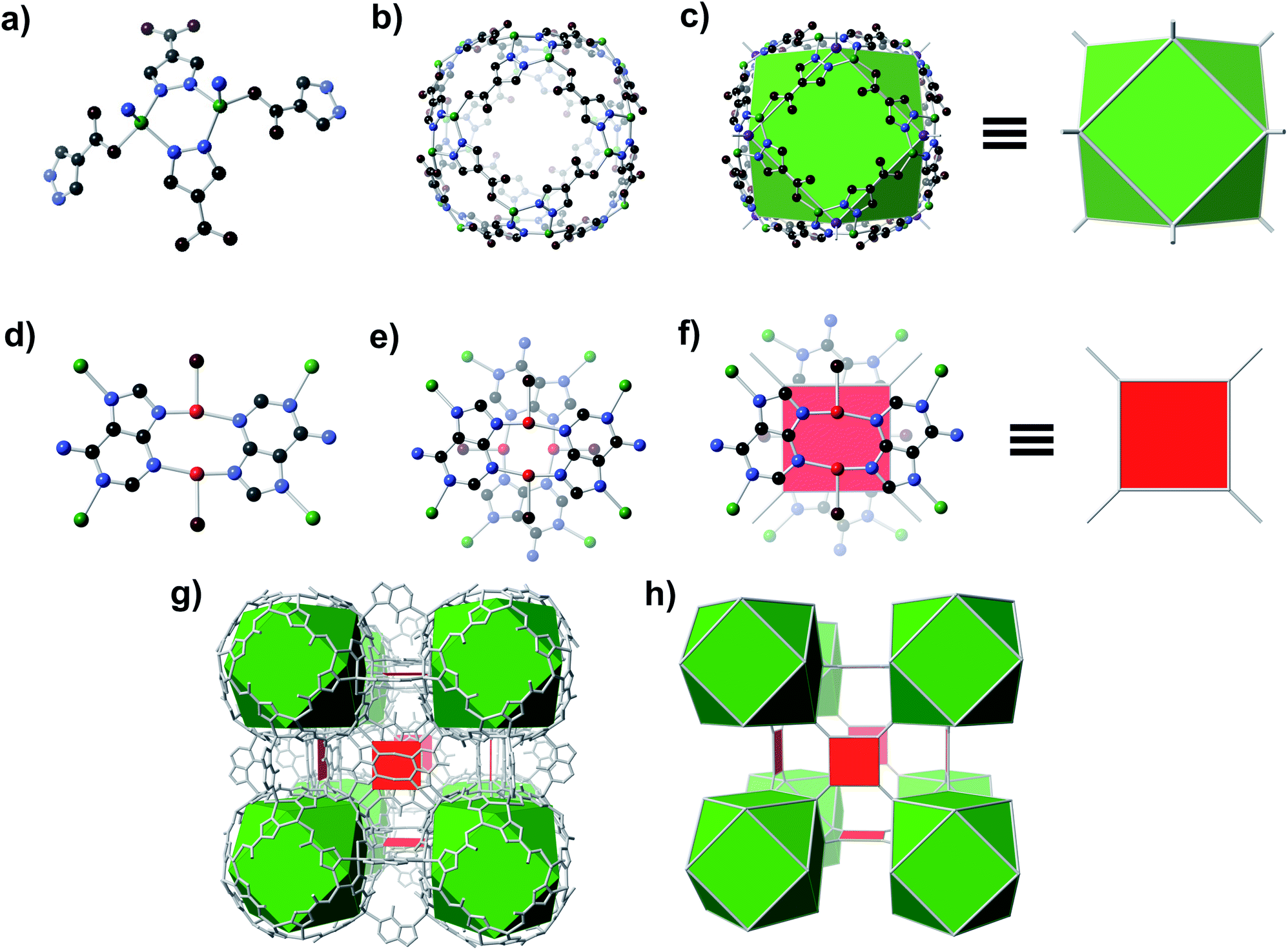 | ||
| Fig. 1 Structure of bMOF-200. (a) Zn-pyz dimers interconnect to create (b) pseudo-spherical cages. Connecting points located at the centre of each dimer results in (c) cuboctahedra. (d) The second structural motif consists of Cu-ad dimers and coordinated solvent (coordinated solvent is reduced to a single oxygen for clarity). Two of these dimers stack perpendicularly to form (e) a Cu4(ad)4(DMF)4 motif, which can be represented as (f) a square. (g) The bMOF-200 framework can thus be simplified to (h) the ftw-a net. Green, red, black, blue, and maroon spheres signify Zn, Cu, C, N, and O atoms, respectively. Purple spheres indicate the points of extension of the Zn-pyz cuboctahedra. | ||
The molecular formula of bMOF-200, Zn2Cu1(pyz)2(ad) (DMF)·2DMF, H2O, was determined through examination and comparison of SC-XRD, elemental analysis (EA), 1H nuclear magnetic resonance (1H NMR) spectroscopy, and thermogravimetric analysis (TGA) data, collectively (see ESI for details; Fig. S1, S2 and Section S7†). It is known that Cu(II) can be reduced in situ during solvothermal reactions in DMF.36 Upon exposure to air, the crystals transition from colourless to light green, presumably due to Cu(I) → Cu(II) oxidation. Assignment of Cu(I) was verified in part based on X-ray photoelectron spectroscopy, which shows evidence of Cu(II) on the surface, but upon etching, Cu(I) in the bulk (Fig. S3†). Continuous wave electron pair resonance (CW-EPR) confirmed the presence of Cu(II) upon exposure of the material to atmosphere (Fig. S4†). The CW-EPR spectrum was simulated with two components, indicating two distinct Cu(II) coordination environments. One component was a broad, featureless signal, likely resulting from dipolar or exchange broadening which occurs when two or more Cu(II) ions are in close proximity.43 The second component had well resolved features from hyperfine interactions. The spectral parameters are available in the ESI.† These EPR parameters are consistent with four-coordinate square planar.44 Alternatively, the spectrum is also generally consistent with recorded three-coordinate Cu(II) species in T- and Y-shaped geometries.45–47 These EPR findings support the expected geometry of the Cu(II) centre. The powder X-ray diffraction (PXRD) pattern (Fig. S5†) of as-synthesized bMOF-200 matches the pattern simulated from SC-XRD, confirming the phase purity of the product material.
bMOF-200 exhibits three distinct cavities, hereafter referred to as P1, P2, and P3 (Fig. 2a). P1 is within the Zn-pyz cage. P2 is the cubic cavity defined by eight Zn-pyz cages at the corners of a cube and six Cu2ad2(DMF)2 dimers on the faces. Both P1 and P2 measure ∼15.5 Å in diameter. A triangular window (∼2.1 Å) sitting on the triangular face of the Zn-pyz cage links P1 to P2. The square windows (∼4.3 Å) on the square faces of the Zn-pyz cages open into the third pore space, P3, which sits between two adjacent Zn-pyz cages. P3 is a small prismatic cavity measuring ∼7 Å in diameter and is decorated with four amino groups from the adeninates. P3 shares a rectangular pore window (∼4.0 × 2.6 Å) with P2, which, in the as-synthesized material, is obstructed by the coordinated DMF molecule. The connectivity of the pores and the resulting diffusive pathways of guest molecules along with pore windows are shown in Fig. 2b–d. The P1 → P2 pathway requires passage through the triangular pore window, and would only be accessible to gases with exceptionally small kinetic diameters (Fig. 2b). In the second pathway (Fig. 2c), molecules would pass through the pore window connecting P2 and P3. The most accessible pathway is along P1 and P3, where molecules would pass through the comparatively larger square pore window connecting P1 and P3 (Fig. 2d). We recognize that the diffusive pathways shown in Fig. 2 represent only the simplest paths through a maximum of two types of pores. In reality, more complex diffusion paths are likely; however, these are much more difficult to conceptualize and model. Thus, we determined that limiting our investigation to the simplest pathways would provide sufficient molecular diffusion information through bMOF-200.
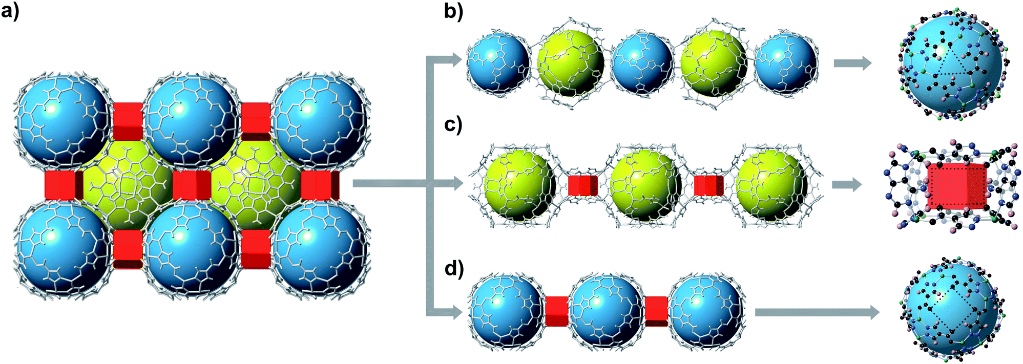 | ||
| Fig. 2 Potential diffusion pathways through bMOF-200. (a) bMOF-200 structure where blue spheres, yellow spheres, and red prisms correspond to P1, P2, and P3, respectively. Pore windows are indicated by dotted lines (right). (b) Pathway P1 → P2 is limited by a triangular pore window (∼2.1 Å). (c) A rectangular window measuring (∼4.0 × 2.6 Å) connects P2 and P3. (d) The largest aperture of ∼4.3 Å is the square window between P1 and P3. | ||
We conducted gas adsorption studies to determine the porosity of bMOF-200 and, more specifically, the accessible pore space given the limiting pore window diameters. Gas adsorption studies were performed on methanol-exchanged material, MeOH-bMOF-200† (see ESI† for experimental details and characterization including SC-XRD, PXRD, EA, NMR, Fourier transform infrared spectroscopy, and TGA, Fig. S6–S9† as well as sample activation procedures). We first collected N2 (kinetic diameter = 3.6 Å) isotherms at 77 K (Fig. S13†) from which we calculated a Brunauer–Emmett–Teller (BET) surface area of 1317 m2 g−1, which accounts for approximately 50% of the theoretical value of ∼2400 m2 g−1 determined using Connolly surface area modelling. This possibly indicates that N2 can only access P1 and P3 with only a small amount entering P2. Comparatively, the CO2 (kinetic diameter = 3.3 Å) isotherm collected at 195 K yielded a BET surface area of 1741.37 m2 g−1, correlating to 74% of the corresponding theoretical surface area (Fig. S14†), indicating that CO2 can access at least a portion of P2. These results, combined with the complex pore circuitry, suggest that molecular sieving is possible in bMOF-200.
Empirical determination of candidate binary gas separations for a given MOF is time consuming and laborious. Due to their crystalline nature, MOFs are highly amenable to computational investigation. To identify a binary gas mixture that might be ideally separated into its individual components using bMOF-200, we used Kohn–Sham density functional theory (DFT) in conjunction with the climbing image nudged elastic band (CI-NEB) method48,49 to study the diffusion path of various gases through the square and triangular apertures of the isolated Zn-pyz cage (P1) (Fig. 3; see ESI† for details). We assigned the starting point as −9 Å, which corresponds to the centre of P1. Generally, there is an attractive interaction between the guest molecule and the atoms near the apertures (0 Å). This interaction is similar both in strength and distance to the calculated physisorption inside the MOF. In the case of H2, the interaction is the strongest near the centre of the square aperture between P1 and P3, and there is only a slight barrier of 0.1 eV to travel across the smaller triangular aperture (P1 to P2). In contrast, the barrier is much higher (0.43 eV) for CO2 to diffuse through the triangular opening into P2. Additionally, CO2 also has to overcome a barrier of 0.15 eV to move across the square opening. Overall, our calculations predict that CO2 diffuses more slowly than H2. More importantly, our calculations show that the diffusion path P1 → P2 through the triangular apertures is significantly more energetically accessible for H2 and hindered for CO2. Therefore, if CO2 were to enter into P2 it would have to occur through P3.
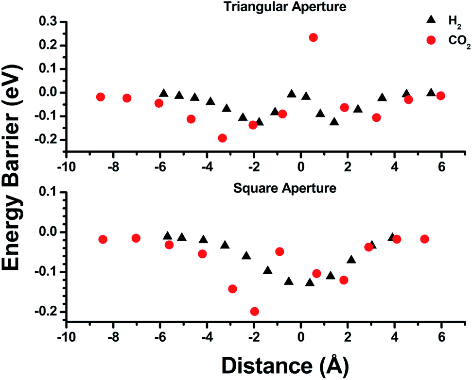 | ||
| Fig. 3 Energy barrier calculations for the triangular (top) and square (bottom) pore windows of P1. The distance values of −9, 0, and 6 Å correspond to the centre of P1, the respective pore window, and the exterior of P1 (toward vacuum). | ||
Further DFT studies were conducted to calculate binding energies of H2 and CO2 in bMOF-200 at various sites within a static framework model (Table S1†). The strength of interaction of both guest molecules with bMOF-200 falls within the range of physisorption, and no chemisorption or strong binding sites were found. Overall, bMOF-200 interacts more strongly with CO2 than H2 by approximately 0.1 eV. This value suggests that the first layer of physisorption is likely dominated by CO2 by roughly 50![[thin space (1/6-em)]](https://www.rsc.org/images/entities/char_2009.gif) :1 at room temperature. Furthermore, the distance for physisorption fell within a narrow window of 2.4 Å to 3.2 Å, which suggests that guest molecules likely travel in single file fashion through all apertures. Diffusion in this manner is likely to occur inside P3, where CO2 interacts most strongly (0.3 eV) with the MOF (Fig. S15†). Four primary amines from four adeninates line P3 creating a Lewis basic environment that acts as a trap for CO2 as they pass single file through the aperture between P1 and P3. In contrast, H2 does not appear to experience strong local interactions at P3 and prefers to bind closer to the Cu sites. Thus, the diffusion through P3 to P2 is likely faster for H2 than CO2. We predicted that the combination of slow diffusion of CO2 through the MOF due to small pore windows and the strong adsorptive interactions with the amine functionalized P3 would make bMOF-200 an effective material for H2/CO2 separations. Pure H2 is used heavily in chemical industries and is produced predominately by steam reforming of natural gas.50 The main by-product of this process is CO2, which can be present in as high as 15% by mass before purification.51 Purification of gases in the production of chemical feedstock is typically done by cryogenic distillation, an expensive and energy intensive process.52 Sorbents, MOFs and ZIFs in particular, have been explored as attractive low-cost alternatives to distillation for H2/CO2 separations.53–64
:1 at room temperature. Furthermore, the distance for physisorption fell within a narrow window of 2.4 Å to 3.2 Å, which suggests that guest molecules likely travel in single file fashion through all apertures. Diffusion in this manner is likely to occur inside P3, where CO2 interacts most strongly (0.3 eV) with the MOF (Fig. S15†). Four primary amines from four adeninates line P3 creating a Lewis basic environment that acts as a trap for CO2 as they pass single file through the aperture between P1 and P3. In contrast, H2 does not appear to experience strong local interactions at P3 and prefers to bind closer to the Cu sites. Thus, the diffusion through P3 to P2 is likely faster for H2 than CO2. We predicted that the combination of slow diffusion of CO2 through the MOF due to small pore windows and the strong adsorptive interactions with the amine functionalized P3 would make bMOF-200 an effective material for H2/CO2 separations. Pure H2 is used heavily in chemical industries and is produced predominately by steam reforming of natural gas.50 The main by-product of this process is CO2, which can be present in as high as 15% by mass before purification.51 Purification of gases in the production of chemical feedstock is typically done by cryogenic distillation, an expensive and energy intensive process.52 Sorbents, MOFs and ZIFs in particular, have been explored as attractive low-cost alternatives to distillation for H2/CO2 separations.53–64
To test the H2/CO2 separation capabilities of bMOF-200, we first conducted column breakthrough experiments. A feed gas ratio of 80:20 H2:CO2 was selected as an approximate to the relative ratios after industrial scale water gas shift (WGS) reactions using methane as the feedstock.65 Other gases such as N2, CH4, and CO, are only present in small amounts in the product stream of the WGS reaction. Two columns were packed with dried bMOF-200 to column lengths of 10 and 50 mm to study the effect of column length. The feed gas was introduced to the packed columns at room temperature and the resulting breakthrough curves were collected (Fig. 4a). The H2 breakthrough time was consistent for both column lengths, indicating very weak interactions between bMOF-200 and H2. However, the CO2 breakthrough time is positively dependent on column length, where more bMOF-200 material leads to longer breakthrough times. Furthermore, a “roll-up”, or overshoot, behaviour is observed in the H2 curves for longer column lengths, which corresponds to the displacement of adsorbed H2 by CO2,66,67 in accordance with our computational studies. These results illustrate the promise of bMOF-200 as a solid sorbent for H2/CO2 separation. Another series of breakthrough experiments were performed to compare bMOF-200 to canonical MOFs bearing similar features to bMOF-200: ZIF-868 because of its small pore windows; UiO-6669 because of its multiple pore diameters; and HKUST-170 because of its unsaturated Cu(II) sites (see ESI for synthesis and characterization details; Fig. S16 and Table S2†). The breakthrough results for all four MOF materials of equivalent column lengths are shown in Fig. 4b. The vertical dotted lines correspond to the timepoint where the relative concentration, C/C0, of CO2 in the effluent is equivalent to 0.01, which we designate as the breakthrough point. All four MOFs exhibit breakthrough times of approximately 2.5 min for H2 due to weak adsorbate–adsorbent interactions and the small kinetic diameter of H2 (2.9 Å) compared to the respective pore window diameters for each MOF. Of the four MOFs, bMOF-200 demonstrated the best H2/CO2 separation capability with a CO2 breakthrough time of 15.5 min. The “roll-up” feature is again observed in the H2 curve for bMOF-200 as well as HKUST-1. In each breakthrough experiment (Fig. 4), abrupt drops in C/C0 correspond to switching to pure carrier gas once equilibrium was achieved. To summarize, bMOF-200 shows the strongest interactions with CO2 among the tested MOFs, a desirable property for H2 purification applications.
 | ||
| Fig. 4 (a) Variable column length breakthrough curves of bMOF-200 (red: 10 mm; black: 50 mm). (b) Breakthrough curves of bMOF-200 (black), HKUST-1 (green), UiO-66 (red), and ZIF-8 (blue) at constant column length of 50 mm. In both plots, dashed lines correspond to H2 and solid lines correspond to CO2. Vertical dotted lines correspond to the time at C/C0 = 0.01 for CO2. Abrupt drops in C/C0 correspond to switching to pure carrier gas. | ||
Membrane technologies hold great promise for the chemical separations industry.52 Therefore, we fabricated membranes of bMOF-200 to further investigate its gas separation capabilities and to benchmark it against other MOF membranes for H2/CO2 separations. bMOF-200 membranes were grown solvothermally on α-alumina substrates using a seeded growth approach71–74 (see ESI for details; Fig. S17†). Scanning electron microscopy (SEM) images of the membranes reveal intergrown cubic crystals of bMOF-200 (Fig. 5a). The average membrane thickness (∼37.3 ± 4.3 μm) was measured from images of fractured membranes acquired at 90° relative to the surface (Fig. 5b). We constructed our own binary gas permeation system for activating and testing membrane gas separations using flow controllers and a gas chromatograph with a thermal conductivity detector (Scheme S1†). For an equimolar H2/CO2 mixture, the average H2 permeability was 5.51 × 10⁻¹¹ ± 6.66 × 10⁻¹³ mol m (m2 s Pa)−1 (164600 Barrer) with a H2/CO2 separation factor of 7.9 ± 1.3 (Table S3†), which exceeds the corresponding Knudsen factor (4.7) and indicates molecular sieving.
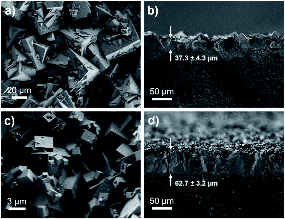 | ||
| Fig. 5 SEM images of top-view and cross-sectional view of bMOF-200 membrane (a and b) and bMOF-201 membrane (c and d). The membrane thicknesses are shown with arrows in (b and d). | ||
Small modifications to the bMOF-200 structure might lead to significant changes, and possible improvement, of its H2/CO2 separation ability. Given its complex structure, adjusting the metrics of bMOF-200 via typical MOF methods (e.g. lengthening linkers, etc.) was not straightforward. However, we reasoned that a more subtle change, such as replacing the Cu site with Zn(II) might be feasible. By slightly altering the synthetic conditions and removing the Cu source, we were able to synthesize the Zn only analogue, which we name bio-MOF-201 (bMOF-201). bMOF-201† is nearly identical to bMOF-200 (structure and composition data are available in the ESI; Fig. S10–S12 and Section S7†) in all aspects except the Cu-ad motif is now replaced by a Zn-ad motif. The consequences of this substitution stem from the tetrahedral geometry of the Zn(II) centres in Zn-ad. Whereas the N–Cu–N angle in bMOF-200 is 167°, the comparable N–Zn–N angle in bMOF-201 is 111° with the Zn(II) projecting into P2 (Fig. 6a). Therefore, based on analysis of the crystal structure, the size of P2 is reduced to ∼12.2 Å in the desolvated MOF. The Zn(II) in Zn-ad is charge-balanced by one adeninate and a coordinated formate/acetate ion, the latter of which resides in the pore window between P2 and P3 (Fig. 6b). The resulting diameter of the pore window connecting P2 and P3 is decreased to ∼0.9 Å. We postulate that the coordinated monocarboxylate will obstruct the P2/P3 window and hinder diffusion of both H2 and CO2, which could possibly affect the H2/CO2 separation factor.
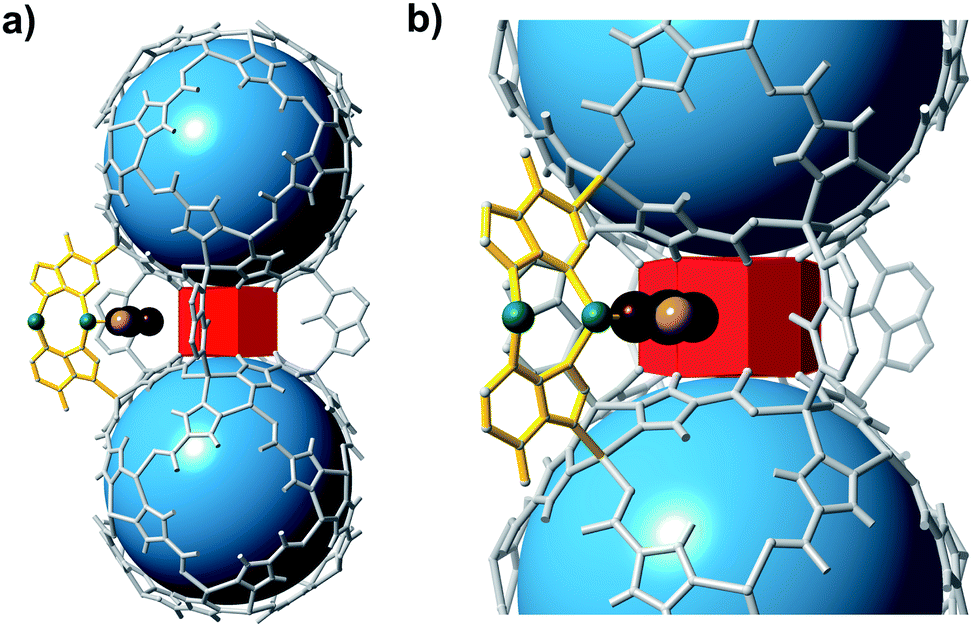 | ||
| Fig. 6 Fragments of bMOF-201 highlighting the structural differences to bMOF-200. (a) Two Zn-pyz cages bridged by four adeninates (grey) and one Zn-ad (yellow). (b) A magnified view of P3 reveals the bent nature of Zn-ad and the location of coordinated monocarboxylate ions (e.g., formate or acetate) within the P2 → P3 pore window. Green, black, maroon, and pink atoms correspond to Zn, C, O, and H atoms, respectively. | ||
Membranes of bMOF-201 were synthesized following a similar solvothermal procedure as for bMOF-200 (see ESI for details; Fig. S18†), and SEM images reveal well-intergrown crystals and a membrane thickness of ∼62.7 ± 3.2 μm (Fig. 5c and d). The average permeability of H2 through bMOF-201 membranes was 3.94 ± 0.13 × 10⁻¹¹ mol m (m2 s Pa)−1 (117700 Barrer), which is a decrease of ∼28% compared to bMOF-200. However, the CO2 permeability decreased by ∼68% in bMOF-201, resulting in a 3-fold increase in separation factor to 22.2 ± 2.2 (Table S3†). We attribute these lower permeability values and the improved separation factor to the occlusion of the P3 → P2 pore window. Further, in bMOF-201, the volume of P3 decreases by approximately 11% relative to bMOF-200, which may lead to stronger interactions between CO2 and the Lewis basic amino groups from adeninate which line this cavity.
Our experimental and computational data indicate that both competitive adsorption and molecular sieving, two of the three mechanisms highlighted by Carreon,75 are responsible for the separation performance of bMOF-200 and bMOF-201 membranes, which exceed the 2008 Robeson upper bound for polymeric membranes (Fig. 7).76 The H2/CO2 separation factor of the bMOF-201 membrane is superior to other MOF membranes (HKUST-1,53 ZIF-69,54 ZIF-8,60 and ZIF-6761) for the same equimolar mixture and under the same testing conditions, while ZIF-100 membranes exhibit separation factors as high as 72, likely due to very efficient molecular sieving.58 The H2 permeability of bMOF-200 and bMOF-201 are amongst the highest in the comparison group, rivalling those observed for HKUST-1 53 and NH2-MIL-53.63 Large H2 permeability values are desirable because they could ultimately reduce membrane area and make the entire gas separation module more compact. We attribute the high H2 permeability to diffusive pathways that are exclusively available to H2. Since CO2 strongly adsorbs within P3, it limits diffusion along P1 → P3 and along P3 → P2. H2, however, can also diffuse along P1 → P2, a pathway not available to CO2.
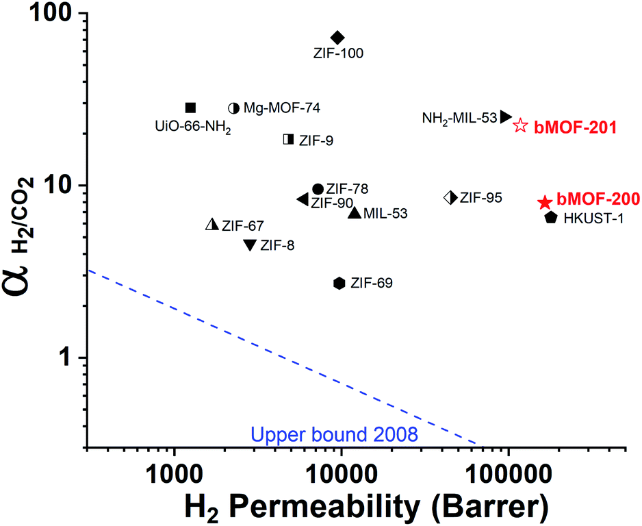 | ||
| Fig. 7 2008 Robeson plot for H2/CO2 separations using polymer membranes. Data for reported MOF membranes and bMOF-200 (filled red star) and bMOF-201 (empty red star) membranes are included for comparison. Data for other MOFs and ZIFs from ref. 53–64. | ||
Conclusion
We have prepared two isoreticular multicomponent MOFs, bMOF-200 and 201, that each contain multiple pore environments and potential molecular diffusion pathways. Through DFT calculated physisorption energy and diffusion barriers, we predicted that bMOF-200 could perform well as a solid sorbent for H2/CO2 separations based on the respective diffusivities and adsorbate–adsorbent interactions for each gas. Column breakthrough and membrane permeation studies revealed efficient H2/CO2 separation using bMOF-200, with membranes exhibiting a H2/CO2 separation factor of 7.9. Replacing a planar Cu site in bMOF-200 with a tetrahedral Zn(II) in bMOF-201 leads to occlusion of one pore window and a decrease in the number of possible diffusion pathways for both H2 and CO2. A consequence of this structural change was significantly improved separation performance: the H2/CO2 separation factor for bMOF-201 membranes was 22.2, nearly three times greater than bMOF-200 membranes. bMOF-201 membranes outperform those of other reported MOFs when considering both H2 permeability and H2/CO2 separation factor.Conflicts of interest
There are no conflicts to declare.Acknowledgements
This project was funded in part by the Department of Energy, National Energy Technology Laboratory, an agency of the United States Government, under the Carbon Capture Field Work Proposal and in part through a support contract with Leidos Research Support Team (LRST, contract 89243318CFE000003) (NLR and YHK). Neither the United States Government nor any agency thereof, nor any of their employees, nor LRST, nor any of their employees, makes any warranty, expressed or implied, or assumes any legal liability or responsibility for the accuracy, completeness, or usefulness of any information, apparatus, product, or process disclosed, or represents that its use would not infringe privately owned rights. Reference herein to any specific commercial product, process, or service by trade name, trademark, manufacturer, or otherwise, does not necessarily constitute or imply its endorsement, recommendation, or favouring by the United States Government or any agency thereof. The views and opinions of authors expressed herein do not necessarily state or reflect those of the United States Government or any agency thereof. In addition, this project was supported in part by an appointment to the Research Participation Program at the National Energy Technology Laboratory, U.S. Environmental Protection Agency, administered by the Oak Ridge Institute for Science and Education through an interagency agreement between the U.S. Department of Energy and EPA (NLR). We acknowledge partial financial support of the U.S. Department of Energy, Office of Science, Office of Basic Energy Sciences as part of the Computational Chemical Sciences Program under award no. DE-SC0018331 (JKJ and LL). Additional research support was provided by the University of Pittsburgh. The authors also acknowledge instructors at the American Crystallography Association Summer Course for Crystallography for assistance with crystal structure refinement. This work was performed, in part, at the Nanoscale Fabrication and Characterization Facility, a laboratory of the Gertrude E. and John M. Petersen Institute of NanoScience and Engineering, housed at the University of Pittsburgh (PXRD and SEM Instrumentation). Calculations were performed at the University of Pittsburgh's Center for Research Computing. The authors also thank Xing Yee Gan for collecting XPS data and Yiwen He for help with membrane illustrations (TOC figure).References
- M. Eddaoudi, D. B. Moler, H. Li, B. Chen, T. M. Reineke, M. O'Keeffe and O. M. Yaghi, Acc. Chem. Res., 2001, 34, 319–330 CrossRef CAS.
- O. M. Yaghi, M. O'Keeffe, N. W. Ockwig, H. K. Chae, M. Eddaoudi and J. Kim, Nature, 2003, 423, 705–714 CrossRef CAS.
- N. W. Ockwig, O. Delgado-Friedrichs, M. O'Keeffe and O. M. Yaghi, Acc. Chem. Res., 2005, 38, 176–182 CrossRef CAS.
- H. Furukawa, K. E. Cordova, M. O'Keeffe and O. M. Yaghi, Science, 2013, 341, 1230444 CrossRef.
- J.-R. Li, R. J. Kuppler and H.-C. Zhou, Chem. Soc. Rev., 2009, 38, 1477–1504 RSC.
- J. Lee, O. K. Farha, J. Roberts, K. A. Scheidt, S. T. Nguyen and J. T. Hupp, Chem. Soc. Rev., 2009, 38, 1450–1459 RSC.
- L. Liu, K. Konstas, M. R. Hill and S. G. Telfer, J. Am. Chem. Soc., 2013, 135, 17731–17734 CrossRef CAS.
- B. Tu, Q. Pang, E. Ning, W. Yan, Y. Qi, D. Wu and Q. Li, J. Am. Chem. Soc., 2015, 137, 13456–13459 CrossRef CAS.
- Q. Pang, B. Tu and Q. Li, Coord. Chem. Rev., 2019, 388, 107–125 CrossRef CAS.
- L. Feng, K.-Y. Wang, G. S. Day and H.-C. Zhou, Chem. Soc. Rev., 2019, 48, 4823–4853 RSC.
- K. Koh, A. G. Wong-Foy and A. J. Matzger, Chem. Commun., 2009, 6162–6164, 10.1039/B904526K.
- S. Furukawa, K. Hirai, K. Nakagawa, Y. Takashima, R. Matsuda, T. Tsuruoka, M. Kondo, R. Haruki, D. Tanaka, H. Sakamoto, S. Shimomura, O. Sakata and S. Kitagawa, Angew. Chem., Int. Ed., 2009, 48, 1766–1770 CrossRef CAS.
- X. Song, T. K. Kim, H. Kim, D. Kim, S. Jeong, H. R. Moon and M. S. Lah, Chem. Mater., 2012, 24, 3065–3073 CrossRef CAS.
- T. Li, J. E. Sullivan and N. L. Rosi, J. Am. Chem. Soc., 2013, 135, 9984–9987 CrossRef CAS.
- O. Kwon, J. Y. Kim, S. Park, J. H. Lee, J. Ha, H. Park, H. R. Moon and J. Kim, Nat. Commun., 2019, 10, 3620 CrossRef.
- T.-Y. Luo, C. Liu, X. Y. Gan, P. F. Muldoon, N. A. Diemler, J. E. Millstone and N. L. Rosi, J. Am. Chem. Soc., 2019, 141, 2161–2168 CrossRef CAS.
- L. Feng, S. Yuan, J.-L. Li, K.-Y. Wang, G. S. Day, P. Zhang, Y. Wang and H.-C. Zhou, ACS Cent. Sci., 2018, 4, 1719–1726 CrossRef CAS.
- D. Kim, G. Lee, S. Oh and M. Oh, Chem. Commun., 2019, 55, 43–46 RSC.
- F. Wang, S. He, H. Wang, S. Zhang, C. Wu, H. Huang, Y. Pang, C.-K. Tsung and T. Li, Chem. Sci., 2019, 10, 7755–7761 RSC.
- H. Deng, C. J. Doonan, H. Furukawa, R. B. Ferreira, J. Towne, C. B. Knobler, B. Wang and O. M. Yaghi, Science, 2010, 327, 846 CrossRef CAS.
- Q. Liu, H. Cong and H. Deng, J. Am. Chem. Soc., 2016, 138, 13822–13825 CrossRef CAS.
- D. N. Dybtsev, H. Chun and K. Kim, Angew. Chem., Int. Ed., 2004, 43, 5033–5036 CrossRef CAS.
- K. Koh, A. G. Wong-Foy and A. J. Matzger, Angew. Chem., Int. Ed., 2008, 47, 677–680 CrossRef CAS.
- J. An, S. J. Geib and N. L. Rosi, J. Am. Chem. Soc., 2009, 131, 8376–8377 CrossRef CAS.
- N. Klein, I. Senkovska, K. Gedrich, U. Stoeck, A. Henschel, U. Mueller and S. Kaskel, Angew. Chem., Int. Ed., 2009, 48, 9954–9957 CrossRef CAS.
- T. Gadzikwa, O. K. Farha, C. D. Malliakas, M. G. Kanatzidis, J. T. Hupp and S. T. Nguyen, J. Am. Chem. Soc., 2009, 131, 13613–13615 CrossRef CAS.
- H. Furukawa, N. Ko, Y. B. Go, N. Aratani, S. B. Choi, E. Choi, A. Ö. Yazaydin, R. Q. Snurr, M. O'Keeffe, J. Kim and O. M. Yaghi, Science, 2010, 329, 424 CrossRef CAS.
- B. J. Burnett, P. M. Barron, C. Hu and W. Choe, J. Am. Chem. Soc., 2011, 133, 9984–9987 CrossRef CAS.
- J. An, O. K. Farha, J. T. Hupp, E. Pohl, J. I. Yeh and N. L. Rosi, Nat. Commun., 2012, 3, 604 CrossRef.
- S. K. Elsaidi, M. H. Mohamed, L. Wojtas, A. J. Cairns, M. Eddaoudi and M. J. Zaworotko, Chem. Commun., 2013, 49, 8154–8156 RSC.
- A. Schoedel, W. Boyette, L. Wojtas, M. Eddaoudi and M. J. Zaworotko, J. Am. Chem. Soc., 2013, 135, 14016–14019 CrossRef CAS.
- J. Qian, F. Jiang, K. Su, J. Pan, Z. Xue, L. Liang, P. P. Bag and M. Hong, Chem. Commun., 2014, 50, 15224–15227 RSC.
- Y.-X. Tan, X. Yang, B.-B. Li and D. Yuan, Chem. Commun., 2016, 52, 13671–13674 RSC.
- C.-C. Liang, Z.-L. Shi, C.-T. He, J. Tan, H.-D. Zhou, H.-L. Zhou, Y. Lee and Y.-B. Zhang, J. Am. Chem. Soc., 2017, 139, 13300–13303 CrossRef CAS.
- H. Jiang, J. Jia, A. Shkurenko, Z. Chen, K. Adil, Y. Belmabkhout, L. J. Weselinski, A. H. Assen, D.-X. Xue, M. O'Keeffe and M. Eddaoudi, J. Am. Chem. Soc., 2018, 140, 8858–8867 CrossRef CAS.
- P. F. Muldoon, C. Liu, C. C. Miller, S. B. Koby, A. Gamble Jarvi, T.-Y. Luo, S. Saxena, M. O'Keeffe and N. L. Rosi, J. Am. Chem. Soc., 2018, 140, 6194–6198 CrossRef CAS.
- S. Yuan, J.-S. Qin, J. Li, L. Huang, L. Feng, Y. Fang, C. Lollar, J. Pang, L. Zhang, D. Sun, A. Alsalme, T. Cagin and H.-C. Zhou, Nat. Commun., 2018, 9, 808 CrossRef.
- B. Tu, L. Diestel, Z.-L. Shi, W. R. L. N. Bandara, Y. Chen, W. Lin, Y.-B. Zhang, S. G. Telfer and Q. Li, Angew. Chem., Int. Ed., 2019, 58, 5348–5353 CrossRef CAS.
- J. An, O. K. Farha, J. T. Hupp, E. Pohl, J. I. Yeh and N. L. Rosi, Nat. Commun., 2012, 3, 604 CrossRef.
- H. Zeng, X.-J. Xie, M. Xie, Y.-L. Huang, D. Luo, T. Wang, Y. Zhao, W. Lu and D. Li, J. Am. Chem. Soc., 2019, 141, 20390–20396 CrossRef CAS.
- J. An, S. J. Geib and N. L. Rosi, J. Am. Chem. Soc., 2010, 132, 38–39 CrossRef CAS.
- T. Li, D.-L. Chen, J. E. Sullivan, M. T. Kozlowski, J. K. Johnson and N. L. Rosi, Chem. Sci., 2013, 4, 1746–1755 RSC.
- A. Bencini and D. Gatteschi, EPR of Exchange Coupled Systems, Dover Publications, 2012 Search PubMed.
- J. Peisach and W. E. Blumberg, Arch. Biochem. Biophys., 1974, 165, 691–708 CrossRef CAS.
- D. W. Randall, S. D. George, P. L. Holland, B. Hedman, K. O. Hodgson, W. B. Tolman and E. I. Solomon, J. Am. Chem. Soc., 2000, 122, 11632–11648 CrossRef CAS.
- P. L. Holland and W. B. Tolman, J. Am. Chem. Soc., 1999, 121, 7270–7271 CrossRef CAS.
- S. Saito, K. Furukawa and A. Osuka, Angew. Chem., Int. Ed., 2009, 48, 8086–8089 CrossRef CAS.
- G. Henkelman and H. Jónsson, J. Chem. Phys., 2000, 113, 9978–9985 CrossRef CAS.
- G. Henkelman, B. P. Uberuaga and H. Jónsson, J. Chem. Phys., 2000, 113, 9901–9904 CrossRef CAS.
- S. Adhikari and S. Fernando, Ind. Eng. Chem. Res., 2006, 45, 875–881 CrossRef CAS.
- K. Li, D. H. Olson, J. Seidel, T. J. Emge, H. Gong, H. Zeng and J. Li, J. Am. Chem. Soc., 2009, 131, 10368–10369 CrossRef CAS.
- D. S. Sholl and R. P. Lively, Nature, 2016, 532, 435–437 CrossRef.
- H. Guo, G. Zhu, I. J. Hewitt and S. Qiu, J. Am. Chem. Soc., 2009, 131, 1646–1647 CrossRef CAS.
- Y. Liu, E. Hu, E. A. Khan and Z. Lai, J. Membr. Sci., 2010, 353, 36–40 CrossRef CAS.
- A. Huang and J. Caro, Angew. Chem., Int. Ed., 2011, 50, 4979–4982 CrossRef CAS.
- Y. Hu, X. Dong, J. Nan, W. Jin, X. Ren, N. Xu and Y. M. Lee, Chem. Commun., 2011, 47, 737–739 RSC.
- A. Huang, Y. Chen, N. Wang, Z. Hu, J. Jiang and J. Caro, Chem. Commun., 2012, 48, 10981–10983 RSC.
- N. Wang, Y. Liu, Z. Qiao, L. Diestel, J. Zhou, A. Huang and J. Caro, J. Mater. Chem. A, 2015, 3, 4722–4728 RSC.
- Y. Sun, C. Song, X. Guo and Y. Liu, ACS Appl. Mater. Interfaces, 2020, 12, 4494–4500 CrossRef CAS.
- X. Zhang, Y. Liu, S. Li, L. Kong, H. Liu, Y. Li, W. Han, K. L. Yeung, W. Zhu, W. Yang and J. Qiu, Chem. Mater., 2014, 26, 1975–1981 CrossRef CAS.
- P. Nian, Y. Li, X. Zhang, Y. Cao, H. Liu and X. Zhang, ACS Appl. Mater. Interfaces, 2018, 10, 4151–4160 CrossRef CAS.
- N. Wang, A. Mundstock, Y. Liu, A. Huang and J. Caro, Chem. Eng. Sci., 2015, 124, 27–36 CrossRef CAS.
- F. Zhang, X. Zou, X. Gao, S. Fan, F. Sun, H. Ren and G. Zhu, Adv. Funct. Mater., 2012, 22, 3583–3590 CrossRef CAS.
- X. Dong, K. Huang, S. Liu, R. Ren, W. Jin and Y. S. Lin, J. Mater. Chem., 2012, 22, 19222–19227 RSC.
- D. Mendes, A. Mendes, L. M. Madeira, A. Iulianelli, J. M. Sousa and A. Basile, Asia-Pac. J. Chem. Eng., 2010, 5, 111–137 CrossRef CAS.
- J. W. Carter and H. Husain, Chem. Eng. Sci., 1974, 29, 267–273 CrossRef CAS.
- G. Li, P. Xiao, D. Xu and P. A. Webley, Chem. Eng. Sci., 2011, 66, 1825–1834 CrossRef CAS.
- K. S. Park, Z. Ni, A. P. Côté, J. Y. Choi, R. Huang, F. J. Uribe-Romo, H. K. Chae, M. O'Keeffe and O. M. Yaghi, Proc. Natl. Acad. Sci. U. S. A., 2006, 103, 10186 CrossRef CAS.
- J. H. Cavka, S. Jakobsen, U. Olsbye, N. Guillou, C. Lamberti, S. Bordiga and K. P. Lillerud, J. Am. Chem. Soc., 2008, 130, 13850–13851 CrossRef.
- S. S. Y. Chui, S. M. F. Lo, J. P. H. Charmant, A. G. Orpen and I. D. Williams, Science, 1999, 283, 1148 CrossRef CAS.
- R. Ranjan and M. Tsapatsis, Chem. Mater., 2009, 21, 4920–4924 CrossRef CAS.
- Y. Pan and Z. Lai, Chem. Commun., 2011, 47, 10275–10277 RSC.
- Z. Xie, T. Li, N. L. Rosi and M. A. Carreon, J. Mater. Chem. A, 2014, 2, 1239–1241 RSC.
- X. Ma, Y. Li and A. Huang, J. Membr. Sci., 2020, 597, 117629 CrossRef CAS.
- M. A. Carreon, Science, 2020, 367, 624 CrossRef CAS.
- L. M. Robeson, J. Membr. Sci., 2008, 320, 390–400 CrossRef CAS.
Footnote |
| † Electronic supplementary information (ESI) available: Experimental protocols, general procedures, compositional data and analysis, gas separation studies, crystallography data. CCDC 2027336 for bMOF-200, 2023790 for MeOH-bMOF-200 and 2023791 for bMOF-201. For ESI and crystallographic data in CIF or other electronic format see DOI: 10.1039/d0sc04979d |
| This journal is © The Royal Society of Chemistry 2020 |