
 Open Access Article
 This Open Access Article is licensed under a Creative Commons Attribution-Non Commercial 3.0 Unported Licence
Heterometallic multinuclear nodes directing MOF electronic behavior†
Otega A.
Ejegbavwo‡
a,
Anna A.
Berseneva‡
 a,
Corey R.
Martin
a,
Gabrielle A.
Leith
a,
Shubham
Pandey
d,
Amy J.
Brandt
a,
Kyoung Chul
Park
a,
Abhijai
Mathur
a,
Sharfa
Farzandh
a,
Vladislav V.
Klepov
a,
Brittany J.
Heiser
a,
Mvs
Chandrashekhar
b,
Stavros G.
Karakalos
c,
Mark D.
Smith
a,
Simon R.
Phillpot
d,
Sophya
Garashchuk
a,
Donna A.
Chen
*a and
Natalia B.
Shustova
*a
a,
Corey R.
Martin
a,
Gabrielle A.
Leith
a,
Shubham
Pandey
d,
Amy J.
Brandt
a,
Kyoung Chul
Park
a,
Abhijai
Mathur
a,
Sharfa
Farzandh
a,
Vladislav V.
Klepov
a,
Brittany J.
Heiser
a,
Mvs
Chandrashekhar
b,
Stavros G.
Karakalos
c,
Mark D.
Smith
a,
Simon R.
Phillpot
d,
Sophya
Garashchuk
a,
Donna A.
Chen
*a and
Natalia B.
Shustova
*a
aDepartment of Chemistry and Biochemistry, University of South Carolina, Columbia, South Carolina 29208, USA. E-mail: shustova@sc.edu
bDepartment of Electrical Engineering, University of South Carolina, Columbia, South Carolina 29208, USA
cCollege of Engineering and Computing, University of South Carolina, Columbia, South Carolina 29208, USA
dDepartment of Materials Science and Engineering, University of Florida, Gainesville, Florida 32611, USA
First published on 27th June 2020
Abstract
Metal node engineering in combination with modularity, topological diversity, and porosity of metal–organic frameworks (MOFs) could advance energy and optoelectronic sectors. In this study, we focus on MOFs with multinuclear heterometallic nodes for establishing metal−property trends, i.e., connecting atomic scale changes with macroscopic material properties by utilization of inductively coupled plasma mass spectrometry, conductivity measurements, X-ray photoelectron and diffuse reflectance spectroscopies, and density functional theory calculations. The results of Bader charge analysis and studies employing the Voronoi–Dirichlet partition of crystal structures are also presented. As an example of frameworks with different nodal arrangements, we have chosen MOFs with mononuclear, binuclear, and pentanuclear nodes, primarily consisting of first-row transition metals, that are incorporated in HHTP-, BTC-, and NIP-systems, respectively (HHTP3− = triphenylene-2,3,6,7,10,11-hexaone; BTC3− = 1,3,5-benzenetricarboxylate; and NIP2− = 5-nitroisophthalate). Through probing framework electronic profiles, we demonstrate structure–property relationships, and also highlight the necessity for both comprehensive analysis of trends in metal properties, and novel avenues for preparation of heterometallic multinuclear isoreticular structures, which are critical components for on-demand tailoring of properties in heterometallic systems.
Introduction
Engineering modular integrative metal platforms, primarily applied in optoelectronic and energy sectors, could bridge the gap between current technology and the great demands for evolving industrial needs.1–14 Metal–organic frameworks (MOFs) provide a unique opportunity for tailoring material properties of interest through metal node engineering.15–22 In particular, the framework topology, ensemble size of the secondary building block, nature of the metal, and presence of unsaturated metal sites can be used as variables for property tunability. Integration of a second metal provides an additional degree of freedom for manipulating or fine-tuning the material profile through variation of the metal-to-metal ratio or charge re-distribution.23–27Herein, we utilize the versatility of metal node nuclearity to establish possible metal–property trends for frameworks containing mononuclear, binuclear, and pentanuclear heterometallic nodes (Scheme 1). We demonstrate changes in the electronic profile as a function of integration of a second metal. Furthermore, we probe changes in the electronic structure as a function of metal ensemble size (i.e., number of metal ions in the metal node), metal nature, and metal ratio (in the example of three series). With support from theoretical modeling, we demonstrate that the experimentally studied changes in the density of states (DOS) near the Fermi edge, distribution of the charge on the metal, as well as band gap and conductivity values correlate with each other and are governed by the nature of the second integrated metal.
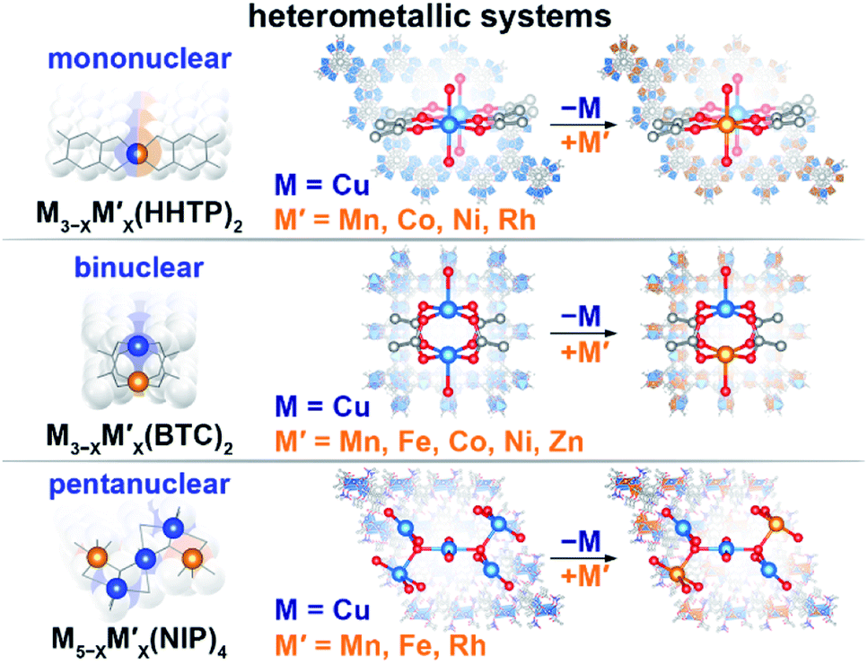 | ||
| Scheme 1 Schematic representation of the studied heterometallic MOFs: (top) mononuclear M3−XM′X(HHTP)2, (middle) binuclear M3−XM′X(BTC)2, and (bottom) pentanuclear M5−XM′X(NIP)4 systems. | ||
Results and discussion
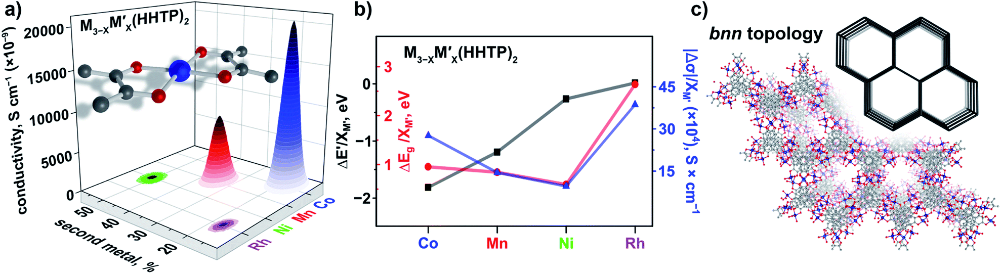
We have chosen frameworks with distinct nuclearity that can accommodate different pairs of metals in their scaffolds. Thus, we studied M3−XM′X(HHTP)2 (M′ = Mn, Co, Ni, and Rh, M = Cu; HHTP3− = triphenylene-2,3,6,7,10,11-hexaone, Fig. 1 and S1†) containing mononuclear metal nodes, M3−XM′X(BTC)2 (M′ = Mn, Fe, Co, Ni, and Zn, M = Cu; BTC3− = 1,3,5-benzenetricarboxylate, Fig. 1, 2, and S1†) with two metal sites per secondary building unit (SBU; binuclear metal nodes), and M5−XM′X(NIP)4 (M′ = Mn, Fe, and Rh, M = Cu; NIP2− = 5-nitroisophthalate; Fig. 1, and S1†) with pentanuclear metal nodes.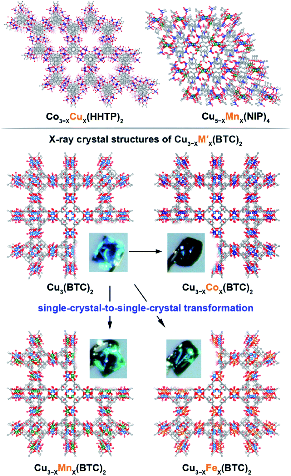 | ||
Fig. 1 (Top) Crystal structures of: (left) mononuclear heterometallic Cu3−XCoX(HHTP)2![[thin space (1/6-em)]](https://www.rsc.org/images/entities/char_2009.gif) 28 and (right) pentanuclear heterometallic Cu5−XMnX(NIP)4 MOFs.29 (bottom) Crystal structures of binuclear monometallic Cu3(BTC)2 and binuclear heterometallic Cu3−XMX-(BTC)2 (M = Mn, Fe, and Co) MOFs. Insets show photographs of the MOF single crystals. The light blue, dark blue, green, orange, grey, and red spheres represent Cu, Co, Mn, Fe, C, and O atoms, respectively. H atoms were omitted for clarity. 28 and (right) pentanuclear heterometallic Cu5−XMnX(NIP)4 MOFs.29 (bottom) Crystal structures of binuclear monometallic Cu3(BTC)2 and binuclear heterometallic Cu3−XMX-(BTC)2 (M = Mn, Fe, and Co) MOFs. Insets show photographs of the MOF single crystals. The light blue, dark blue, green, orange, grey, and red spheres represent Cu, Co, Mn, Fe, C, and O atoms, respectively. H atoms were omitted for clarity. | ||
Comprehensive MOF analysis was performed using single-crystal X-ray diffraction, powder X-ray diffraction (PXRD), X-ray photoelectron spectroscopy (XPS), inductively coupled plasma mass spectrometry (ICP-MS), conductivity measurements, diffuse reflectance (DR) spectroscopy, thermogravimetric analysis (TGA), and density functional theory (DFT) studies. All prepared heterometallic MOFs were analyzed by PXRD to ensure crystallinity before and after transmetallation. The metal ratio was verified by ICP-MS analysis. Notably, all ICP-MS studies were performed on samples that underwent an extensive washing (∼one week) procedure using a Soxhlet apparatus to remove any residual M′-salts utilized for the integration of a second metal (M′). The discussion in this paper will be organized in the following order: preparation and characterization of the monometallic and corresponding heterometallic frameworks, then comprehensive analysis based on XPS, DR spectroscopy, and conductivity measurements with the support of theoretical modeling. The main emphasis of the presented studies is to reveal possible relationships between the observed experimental and theoretical values as a function of the chosen metal M′, i.e., establishing M′–property trends.
Preparation of monometallic and heterometallic systems mononuclear heterometallic M3−XM′X(HHTP)2 frameworks
We used monometallic M–MOFs as a template for integration of the second metal through post-synthetic ion metathesis. For preparation of heterometallic mononuclear Cu2.5Co0.5-HHTP, the monometallic parent scaffold, Co9(HHTP)4, was used; Cu3(HHTP)2 was used as a precursor for the synthesis of Cu2.0Mn1.0-HHTP, Cu1.5Ni1.5-HHTP, and Cu2.6Rh0.4-HHTP MOFs (Table 1, for more details see ESI†). The choice of the scaffold precursor was determined by feasibility of transmetallation (see more details below), preservation of framework integrity, and reasonable times for cation exchange. The selected experimental conditions are provided in Table 1. The M-HHTP frameworks with bnn topology (Fig. 1) consist of two-dimensional layers with alternation that can be changed as a function of the metal.28 Cu3(HHTP)2 possesses AAAA stacking while layers in the cobalt-containing Co9(HHTP)4 structure alternates in the ABAB sequence.28 These distinct structural changes can be detected by the use of PXRD after the transmetallation procedure. For instance, the PXRD pattern of Co9(HHTP)4 shows prominent peaks at 2θ = 4.5°, 9.2°, and 13.9° (corresponding to the (100), (200), and (300) reflections, respectively) indicating the long-range order within the ab plane (Fig. S2†).28,30 In the case of Cu3(HHTP)2, the peak at 2θ = 13.9° (characteristic of Co9(HHTP)4) is absent in the PXRD pattern while the peak at 12.4° (characteristic of Cu3(HHTP)2) is detectable (Fig. S2†). In the case of heterometallic Cu3−XCoX(HHTP)2 MOF, the peak at 2θ = 13.9° in the PXRD pattern (indicative of the presence of the monometallic cobalt-containing MOF) was absent, and the novel peaks at 2θ = 12.4° and 16.4°, characteristic of the monometallic copper-based analogue, are observed (Fig. S2†). These distinct differences in PXRD patterns are in line with the ICP-MS data that demonstrates integration of 83% of copper in the parent Co9(HHTP)4 matrix. All MOF samples were analyzed by PXRD to ensure crystallinity before and after transmetallation (Fig. S2 and S3†). PXRD analysis demonstrated that all samples possess AAAA stacking. Thermostability of the Cu3−XCoX(HHTP)2 samples was studied by TGA and the corresponding TGA plots are shown in Fig. S4.†| Heterometallic MOF | Synthesis T (°C)/time (h) | Evacuation T (°C)/time (h) |
|---|---|---|
| Cu2.0Mn1.0-HHTP | 85/16 | 85/6 |
| Cu2.5Co0.5-HHTP | 85/16 | 85/6 |
| Cu1.5Ni1.5-HHTP | 85/16 | 85/6 |
| Cu2.6Rh0.4-HHTP | 85/16 | 85/6 |
| Cu2.8Mn0.2-BTC | 90/24 | 160/24 |
| Cu2.6Mn0.4-BTC | 90/48 | 160/24 |
| Cu2.4Mn0.6-BTC | 90/72 | 160/24 |
| Cu2.7Fe0.3-BTC | 90/24 | 160/24 |
| Cu2.6Fe0.4-BTC | 90/48 | 160/24 |
| Cu2.2Fe0.8-BTC | 90/72 | 160/24 |
| Cu2.9Co0.1-BTC | 90/12 | 160/24 |
| Cu2.82Co0.18-BTC | 90/42 | 160/24 |
| Cu2.79Co0.21-BTC | 90/72 | 160/24 |
| Cu2.7Ni0.3-BTC | 90/74 | 160/24 |
| Cu1.6Zn1.4-BTC | 25/24 | 160/24 |
| Cu4.8Mn0.2-NIP | 25/3.5 | 85/12 |
| Cu4.4Fe0.6-NIP | 25/1 | 85/12 |
| Cu4.8Rh0.2-NIP | 60/5 | 85/12 |
Binuclear heterometallic M3−XM′X(BTC)2 frameworks
The Cu3(BTC)2 framework, possessing tbo topology and containing a binuclear paddle-wheel SBU31 (Scheme 1, Fig. 1, 3a, and S6†), was used as a template for the synthesis of heterometallic MOFs containing Cu/Fe, Cu/Mn, Cu/Ni, and Cu/Co pairs of metals. As a result, the following compositions were prepared: CumFen-BTC, (m = 2.7, n = 0.3; m = 2.6, n = 0.4; m = 2.2, n = 0.8), CumMnn-BTC, (m = 2.8, n = 0.2; m = 2.6, n = 0.4; m = 2.4, n = 0.6), CumCon-BTC, (m = 2.9, n = 0.1; m = 2.82, n = 0.18; m = 2.79, n = 0.21), and CumNin-BTC (m = 2.7, n = 0.3).Despite the fact that a typical MOF transmetallation procedure results in polycrystalline samples, we were able to preserve single crystals of BTC-based frameworks containing Cu/Fe, Cu/Mn, and Cu/Co pairs. The crystal structures and crystallographic data for the heterometallic Cu2.4Fe0.6-BTC, Cu1.8Fe1.2-BTC, Cu2.4Mn0.6-BTC, Cu2.3Mn0.7-BTC, Cu1.9Co1.1-BTC, and Cu1.1Co1.9-BTC MOFs are shown in Fig. 1 and Tables S1 and S2,† highlighting the isoreticular nature of the monometallic and heterometallic analogues. For the synthesis of the zinc-containing Cu3−XZnX(BTC)2 system, a different parent scaffold, Zn3(BTC)2, was chosen due to unsuccessful attempts to integrate zinc in the copper-containing monometallic framework, Cu3(BTC)2. Thus, to prepare CumZnn-BTC, (m = 1.6, n = 1.4), we soaked Zn3(BTC)2 in a 1.01 M ethanol solution of Cu(NO3)2 at room temperature for 24 hours (Table 1). All BTC-based samples were analyzed by PXRD to ensure crystallinity before and after transmetallation (Fig. S7–S12†). Thermostability of the Cu3−XM′X(BTC)2 samples was determined by TGA and the corresponding TGA plots are shown in Fig. S13–S15.†
Pentanuclear heterometallic M5−XM′X(NIP)4 frameworks
The Cu5(NIP)4(OH)2 (Cu5(NIP)4)29 framework was used as a precursor for the synthesis of the corresponding heterometallic M5−XM′X(NIP)4 systems under the conditions shown in Table 1. In particular, heterometallic MOFs, Cu5−XM′X(NIP)4 (M′ = Mn, Fe, and Rh), were prepared by soaking or heating Cu5(NIP)4 in an N,N-dimethylformamide solution of the corresponding chloride M′-salts (more details described in the ESI). Transmetallation resulted in the preparation of novel Cu4.8Mn0.2-NIP, Cu4.4Fe0.6-NIP, and Cu4.8Rh0.2-NIP systems according to ICP-MS analysis. Rapid incorporation of 12% of iron cation inside the Cu5(NIP)4 lattice occurred even during one hour at room temperature. However, exceeding one hour of transmetallation resulted in loss of framework integrity. A similar crystallinity loss was observed for manganese cation integration after three and a half hours at room temperature. In the case of rhodium transmetallation, Cu5(NIP)4 preserves its integrity after a five-hour soaking procedure with stirring and heating at a moderate temperature (Table 1). All MOF samples were analyzed by PXRD to ensure crystallinity before and after transmetallation (Fig. S17 and S18†). Thermostability of the Cu5−XM′X(NIP)4 samples was determined by TGA and the corresponding TGA plots are shown in Fig. S19 and S20.†Evaluation of M⋯M Interactions by the Voronoi–Dirichlet Approach. Valence Band Structure, Density of States, Conductivity Measurements, Metal Oxidation States, and Optical Data Analysis in Combination with Theoretical Modeling.
To probe metal⋯metal interactions in the discussed mononuclear, binuclear, and pentanuclear systems, we employed the Voronoi–Dirichlet tessellation approach.32,33 In general, a Voronoi–Dirichlet polyhedron (VDP) for a selected atom in the crystal structure is shaped by an intersection of the planes dissecting the center of the lines that connect the selected atom with all surrounding atoms in the structure and are perpendicular to these lines. As a result, every inner point of a VDP is closer to the selected atom than to any other atom in the structure. This approach allows for estimation of interaction strength between two atoms, for instance, metals in the nodes, by calculating the solid angle (Ω) of a shared face of their VDP, expressed as percent of total VDP surface area as shown in eqn (1).32
| Ω = S/Stotal × 100% | (1) |
 | ||
| Scheme 2 (Left) VDP of the cobalt atom in the crystal structure of mononuclear Co9(HHTP)4,28 (middle) VDP of the copper atoms in the crystal structures of binuclear Cu3(BTC)2,31 and (right) pentanuclear Cu5(NIP)4.29 The light blue, dark blue, and red spheres represent Cu, Co, and O atoms, respectively. The contact atoms except oxygen for the pentanuclear SBU were omitted for clarity. Gray arrows indicate a shared face of VDP with the area S, while Stotal stands for the total area of the VDP. | ||
For performance of the VDP analysis, we need to have access to single-crystal X-ray data, and thus, we chose Co9(HHTP)4 as an example of the mononuclear system.28 In Co9(HHTP)4, the cobalt atoms do not share a common VDP face, indicating no interactions between the metal atoms that is also supported by the distance between the metal atoms of 4.96 Å (Scheme 2). In Cu3(BTC)2 with binuclear nodes, the shortest distance between the metal atoms is 2.63 Å, and a corresponding solid angle was found to be 9.46% (Scheme 2). For comparison, an atom in an idealized octahedral environment has six VDP faces with a solid angle of 16.7% for each bond. In a pentanuclear Cu5(NIP)4 node, the M⋯M distances vary in a range of 3.20–3.50 Å (Table S5†).29 There are two unique non-zero contacts in the copper-based node with Ω of 2.60% per contact, giving a total value of 5.20% for the central Cu atom. Despite higher metal node nuclearity observed in Cu5(NIP)4, estimated Ω for Cu5(NIP)4 is almost twice as small as that found in Cu3(BTC)2. Notably, the constructed polyhedra were built taking all atoms in the second and third coordination spheres into account, and only metal nodes are shown in Scheme 2 for clarity. According to the VDP analysis, M⋯M interactions are not simply a function of metal node nuclearity, and therefore, a more in-depth crystallographic analysis is required for each system. BTC-MOFs could be used as a platform for understanding M–property correlations due to the pronounced M⋯M interactions.
To evaluate a large number of monometallic and heterometallic systems, we employed XPS as a powerful and non-destructive tool for fast prescreening of the changes in the valence band (VB) region. We simultaneously monitored the DOS near the Fermi level (EF, binding energy = 0 eV) and changes in the oxidation states of metals integrated into the MOF lattice. Prior to experimental analysis by XPS, all MOF samples were evacuated using the procedures based on the TGA results for the corresponding frameworks (Table 1, Fig. S4, S13–S15, S19, and S20†). The results acquired from XPS studies were compared against those obtained from DR analysis, conductivity measurements, and theoretical modeling. We initially began with M3−XM′X(BTC)2 due to a wider compositional range and diversity of metals available for integration inside the lattice without degradation of the parent framework.
Binuclear heterometallic M3−XM′X(BTC)2 frameworks
The VB spectra of the evacuated heterometallic Cu3−XM′X(BTC)2 (M′ = Mn, Fe, Co, Ni, and Zn) MOFs are shown in Fig. 2, S23, and S24.† Based on the data, we have evaluated the onset of the VB as the binding energy at the intersection of a fitted line, representing the average baseline signal, and a fitted tangent line, representing the slope of intensity vs. binding energy (Table S6 and Fig. S24; see more information in the ESI†). Fig. 3b demonstrates the dependence of (E′* − E′)/XM′ as a function of the second metal (where ΔE′ = E′* − E′; E′ and E′* = VB onsets calculated for Cu3−XM′X(BTC)2 and Cu3(BTC)2, respectively; XM′ = mole fraction of incorporated M′). As shown in Fig. 3b and Table S7,† the highest value of (E′* − E′)/XM′ is found for M′ = Co and the values for M′ = Ni, Mn, Fe, and Zn are 7–27-fold lower (Table S7†). Furthermore, the (E′* − E′)/XM′ values for M′ = Ni, Mn, Fe, and Zn are the same within three standard errors, as shown in Fig. S22.† The calculated (E′* − E′)/XM′ values could be considered as a descriptor for MOF electronic properties in terms of conductivity since it serves as a measure of DOS near EF. For M′ = Co, DOS within 0.5 eV of EF is observed (characteristic of a semiconductor),34 and therefore, ΔE′/XM′= (E′* − E′)/XM′ (where E′* = 1.88 eV) is a relatively large number after normalization to the mole fraction of integrated M′. In contrast, for M′ = Ni, Mn, Fe, and Zn, the larger energy gap between the valence band onset and EF (larger E′) is more typical of an insulating material and results in smaller values of ΔE′/XM′ as shown in Fig. 3b. We anticipate that the ΔE′/XM′ values describe the electronic properties of the MOFs and should correlate with experimental conductivity and optical properties (Fig. 3a). To test this hypothesis, we initially studied heterometallic samples using DR spectroscopy. The optical band gaps (Eg) of the evacuated BTC-systems were estimated based on the Tauc plot analysis shown in Fig. 2 and S26.† As in the case of ΔE′/XM′ values, the same dependence of (Eg* − Eg)/XM′ from the nature of the metal was observed (Eg* and Eg = estimated optical band gaps for Cu3(BTC)2 and Cu3−XM′X(BTC)2, respectively; XM′ = mole fraction of incorporated M′, Fig. 3b). Estimated ΔEg/XM′ is in line with the tendency observed for ΔE′/XM′, i.e., the largest values for both ΔE′/XM′ and ΔEg/XM′ correspond to Co/Cu heterometallic samples (Table S9†). As a next step, we evaluated changes in conductivity of these samples. For that, we performed pressed-pellet conductivity measurements using a home-built two-probe device.35 The list of measured values and a description of sample preparation are presented in Table S10 and the ESI,† respectively. In our studies, we did not focus on each separate measured value (that could be affected by many parameters) but rather tried to establish trends similar to those discussed for optical and VB data (vide supra). Indeed, |(σ − σ*)|/XM′ demonstrated the exact same behavior as that observed for band gap, ΔEg/XM′, values (Fig. 3b, |Δσ| = |σ – σ*|; σ* and σ = conductivity values for Cu3(BTC)2 and Cu3−XM′X(BTC)2, respectively; XM′ = mole fraction of incorporated M′). The corresponding graphs with error bars are shown in Fig. S22.† To summarize, all three M′−function correlations, ΔEg/XM′, ΔE′/XM′, and |Δσ|/XM′ follow the same trend (Fig. 3b) in that the values are highest for Co and generally decrease as Ni, Mn, Fe, and Zn are substituted as M′, respectively. Moreover, ΔEg/XM′ and |Δσ|/XM′ demonstrate the same dependence for Cu3−XM′X(BTC)2 where M′ = Ni, Mn, Fe, and Zn. Based on the experimentally acquired data, we can conclude that integration of cobalt as M′ inside Cu3−XM′X(BTC)2 resulted in a decrease of the optical band gap, appearance of a more pronounced DOS near EF, and enhancement of conductivity values per cobalt atom, whereas the presence of zinc in the Cu3−XM′X(BTC)2 lattice led to an increase in band gap and promotion of insulating behavior. Both of these statements are supported by theoretical calculations as described later.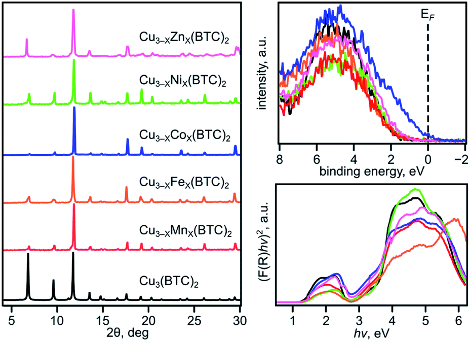 | ||
| Fig. 2 (Left) PXRD patterns of: Cu3(BTC)2 (black), Cu2.4Mn0.6-BTC (red), Cu2.2Fe0.8-BTC (orange), Cu2.8Co0.2-BTC (dark blue), Cu2.7Ni0.3-BTC (light green), and Cu1.6Zn1.4-BTC (pink). (top right) XPS data showing the valence band regions for: Cu3(BTC)2 and Cu3−XM′X(BTC)2 (M′ = Mn, Fe, Co, Ni, and Zn) following the same color coding as the PXRD patterns. (bottom right) Tauc plots ([F(R) × hν]2vs. hν) constructed from DR data for Cu3(BTC)2 and Cu3−XM′X(BTC)2 (where M′ = Mn, Fe, Co, Ni, and Zn) following the same color coding as the PXRD patterns. | ||
 | ||
| Fig. 3 (a) A binuclear paddle-wheel metal node and graphical illustration of the results of conductivity measurements obtained for Cu3−XM′X(BTC)2 (M′ = Mn, Fe, and Co) as a function of M′ percentage. (b) Changes in conductivity (|Δσ|, dark blue triangles), experimentally measured band gaps (ΔEg(exp), red circles), calculated band gaps (ΔEg(calc), orange pentagons), estimated valence band onset values from the XPS data (ΔE′, black squares), and calculated (zCu × XCu) values (green pentagons) as a function of M′ performed for M3−XM′X(BTC)2 (M′ = Co, Ni, Mn, Fe, and Zn). The ΔEg, ΔE′, and |Δσ| values have been normalized to the mole fraction of M′ (XM′). The corresponding graphs with error bars are shown in Fig. S22.† (c) Crystal structure of parent Cu3(BTC)2 possessing the tbo topology (shown in inset). The red, gray, and light blue spheres represent O, C, and Cu atoms, respectively. H atoms were omitted for clarity. | ||
The XPS studies not only allowed us to estimate (E′* − E′)/XM′ values, but also shed light on the oxidation states of the incorporated metals (M′). As previously shown for the monometallic Cu3(BTC)2 system, the Cu(2p3/2) region of the XPS spectrum consists of two peaks at 933.0 and 934.7 eV that can be assigned to Cu1+ and Cu2+, respectively.36 For the heterometallic Cu3−XM′X(BTC)2 MOFs, a similar trend was observed, and the presence of Cu1+ and Cu2+ peaks was also detected (Fig. S27†). Analysis of the corresponding XPS regions for incorporated M′ allowed us to conclude that M′ inside Cu3−XM′X(BTC)2 possesses the following oxidation states: +2 (Co); +2 (Ni); +2 (Mn); +2 and +3 (Fe); and +2 (Zn). Based on the XPS data, we attempted to estimate how (zCu × XCu) and (zM′ × XM′) changes as a function of M′ with the assumption that the total charge of cations remains constant (eqn (2)).
| zM′ × XM′ + zCu × XCu = constant | (2) |
We estimated the average charge on the copper ions by peak fitting the Cu(2p3/2) XPS data with contributions from Cu1+ and Cu2+ (Fig. S27†). For instance, if the ratio of Cu1+ to Cu2+ is 0.5 to 0.5 then zCu = 0.5 × (1+) + 0.5 × (2+) = (1.5+), where 1+ and 2+ are the charges on copper. The mole fractions of XM′ and XCu were estimated from the ICP-MS data. To find the constant from eqn (2), we used XPS data for monometallic Cu3(BTC)2. In this case, (zM′ × XM′) equals zero because of the absence of a second metal, M′, in the Cu3(BTC)2 structure. Therefore, zCu × XCu + zM′ × XM′ = zCu × (1) + zM′ × (0) = zCu. The constant in eqn (2) was estimated to be 1.69. Finally, the zM′ value was also calculated based on eqn (2) since zCu and XCu (or XM′) was estimated from the XPS and ICP-MS data, respectively. The corresponding values of (zCu × XCu)/(zM′ × XM′) for heterometallic BTC-samples with an integrated metal (M′) were found to be 1.44/0.25 (Co), 1.35/0.34 (Ni), 1.17/0.52 (Mn), 1.10/0.59 (Fe), and 0.89/0.79 (Zn, Table 2 and Fig. S27†). The calculated zCu × XCu follows the trends established for the experimental optical band gap and conductivity values (Fig. 3b). Thus, increase in the copper charge and its mole fraction correlates with the corresponding optical band gap decrease.
| M′= | Co | Ni | Mn | Fe | Zn |
|---|---|---|---|---|---|
| a Samples with the maximum M′/Cu ratio were chosen for analysis. | |||||
| Cu 3−X M′X(BTC)2 | |||||
| z Cu × XCu | 1.44 | 1.35 | 1.17 | 1.10 | 0.89 |
| z M′ × XM′ | 0.25 | 0.34 | 0.52 | 0.59 | 0.79 |
| E′, eV | 0.29 ± 0.02 | 1.72 ± 0.12 | 1.66 ± 0.17 | 1.76 ± 0.14 | 1.50 ± 0.09 |
| σ (×1011), S × cm−1 | 396.00 ± 0.19 | 101.00 ± 0.05 | 62.40 ± 0.08 | 36.30 ± 0.03 | 31.50 ± 0.01 |
| E g(exp), eV | 3.22 ± 0.17 | 3.32 ± 0.13 | 3.30 ± 0.14 | 3.24 ± 0.10 | 3.27 ± 0.09 |
| E g(calc), eV | 3.32 | 3.50 | 3.65 | 3.70 | 3.90 |
|
|||||
| Cu 3−X M′X(HHTP)2 | |||||
| z Cu × XCu | 1.19 | 0.77 | 1.01 | — | — |
| z M′ × XM′ | 0.33 | 0.75 | 0.51 | — | — |
| E′, eV | 1.20 ± 0.07 | 1.38 ± 0.08 | 1.11 ± 0.06 | — | — |
| σ (× 107), S × cm−1 | 205.00 ± 1.36 | 0.99 ± 0.01 | 87.70 ± 0.88 | — | — |
| E g, eV | 1.06 ± 0.01 | 1.20 ± 0.01 | 1.17 ± 0.01 | — | — |
To rationalize the observed experimental trends, we analyzed the electronic structure computed using the Vienna ab initio simulation package (VASP)37,38 with the plane wave basis set. The total and partial DOS were obtained from the single point calculations at experimental geometries using the hybrid HSE06 method39 followed by geometry optimization (see the ESI†). The results revealed that substitution of one of the two metal centers in the metal node of the MOF truncated model, Cu2(OAc)4 (Fig. S34†), resulted in an increase of the band gap in the order Co < Ni < Mn < Fe < Zn (Table 2) that is in agreement with the Eg values estimated from the Tauc plot analysis (Fig. S26†). Calculated ΔEg(calc)/XM′ also follows the experimental trend shown in Fig. 3b. The partial-DOS analysis suggests that the decrease in the band gap is associated with changes in the electronic structure near the Fermi level. In the case of M′ = Co, Ni, Mn, and Fe, the highest occupied molecular orbital (HOMO) is dominated by M′-3d-orbitals after substitution, in contrast to parent monometallic Cu2(OAc)4 where the HOMO is occupied by the O-2p-orbitals (Fig. 4a–e and S35†). At the same time, the lowest unoccupied molecular orbital (LUMO) is dominated by the Cu-3d-orbitals in the case of monometallic and heterometallic clusters. Integration of zinc inside the copper paddle-wheel node, according to theoretical calculations, does not significantly alter the electronic structure, and the band gap edges remain the same (Fig. 4f). The Zn-3d-orbitals lie deep inside the occupied orbitals and the band edges are still dominated by O-2p- and Cu-3d-orbitals that represent the HOMO and LUMO, respectively. These results indicate that cobalt substitution decreases the band gap of Cu-MOF the most, followed by band gaps for Ni < Mn < Fe; while zinc integration has almost no effect on the band gap.
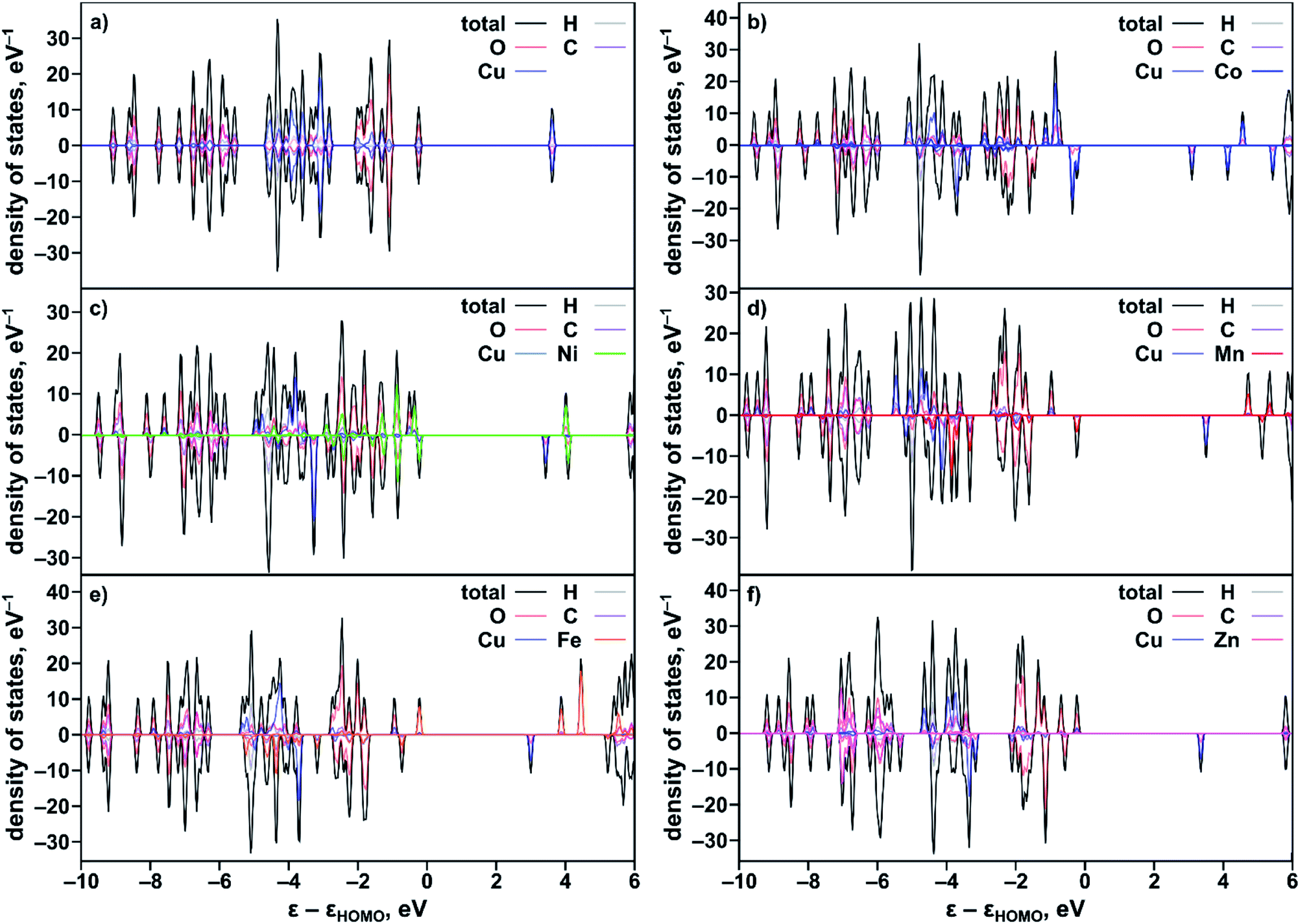 | ||
| Fig. 4 Partial and total DOS of the studied heterometallic binuclear M3−XM′X(BTC)2 systems calculated using a truncated cluster model, Cu2(OAc)4, and the HSE06 exchange-correlation functional: (a) Cu2(OAc)4, (b) CuCo(OAc)4, (c) CuNi(OAc)4, (d) CuMn(OAc)4, (e) CuFe(OAc)4, and (f) CuZn(OAc)4. | ||
The results of the performed Bader charge, atomic-dipole-corrected-Hishfeld-atomic charge, and Mulliken-charge analysis based on the B3LYP-D3/m6-31G* and ωB97X-V/6-31G* methods using the optimized geometry for the CuM′(OBn)4 (OBn− = benzoate; M′ = Co, Ni, Mn, Fe, and Zn) cluster are given in Table S13 and described in the ESI.†
As a next step in our analysis, we compared the observed trends for heterometallic MOFs with those known for doped inorganic oxides, which exhibit the electronic property tunability that has been studied for several decades.40,41 The challenge in the literature search was mainly associated with the typically narrow range of metals traditionally used as dopants for one set of studies. However, we found that Deepak and co-workers reported tuning of electronic properties of ZnO (a wurtzite-type structure) by doping with 3d divalent metals such as M′ = Co, Ni, and Mn.40 It was found that an increase in dopant concentration caused a decrease in the ZnO band gap values (Eg(ZnO) = 3.30 eV).40 Indeed, the reported Eg values of zinc oxide doped with Co, Ni, and Mn were found to be 2.95, 3.24, and 3.28 eV, respectively, for a substitution percentage of M′ at 5% (Fig. 5). Analysis of electronic properties revealed that a decrease in the band gap in the case of the Co dopant is the highest among the three systems, followed by Ni and Mn incorporated samples (Fig. 5). Such a behavior was attributed to the sp–d exchange interactions between electrons in conduction and valence bands (that are mostly s and p electrons) and dopant localized d electrons.42 In line with this trend, Lin and co-workers reported a theoretical study of the doped anatase phase of TiO2 with the same transition metals, M′ = Mn, Co, and Ni.41Ab initio band calculations based on DFT with the plane wave basis set were performed on the supercell of the anatase structure with a substitution percentage of M′ at 12.5%. The trend for Co, Ni, and Mn metals obtained in this study is the following: Eg (1.78 eV for Co:TiO2) < Eg (2.23 eV for Ni:TiO2) < Eg (2.32 eV for Mn:TiO2, Fig. 5). It has been demonstrated that the dopant energy levels occur in the middle of the band gap (at an “intermediate level”), leading to band gap narrowing.41 While TiO2 valence and conduction bands are dominated by O-2p and Ti-3d states, respectively, valence and conduction bands are still formed by O-2p and Ti-3d states modified by the dopant metal. On the example of these transition-metal doped oxides, we demonstrate that the trend established for ΔEg(lit.)/XM′ is in line with the trends found in our studies for experimental and calculated ΔEg(Cu3−XM′X(BTC)2)/XM′ (M′ = Co, Ni, and Mn, Fig. 5). Access to crystallographic data of heterometallic MOFs such as Cu3−XM′X(BTC)2 (M′ = Co, Fe, and Mn, Fig. 3c) allowed us to evaluate the dependence of a unit cell parameter, a, (Cu3−XM′X(BTC)2 belongs to the Fm![[3 with combining macron]](https://www.rsc.org/images/entities/char_0033_0304.gif) m space group) as a function of the integrated metal, and therefore survey possible structural distortion. Maximum deviation in the unit cell parameter, a, in comparison with that of pristine Cu3(BTC)2 was found to be 0.09% for Cu1.8Fe1.2-BTC while for the rest of the BTC-systems Δa/a* varied in a range of 0.007% to 0.06% (Tables S3 and S4†). Notably, the distance comparison was performed on crystal structures with several M/M′ pairs (M = Cu, M′ = Co; M = Cu, M′ = Fe; and M = Cu, M′ = Mn), collected at the same temperature, 100 K. The evaluation of possible changes in Cu⋯M′ metal distances demonstrated that the largest change (1.02%) was observed for Cu2.4Mn0.6-BTC. The largest change in distances between metal nodes (0.09%) was observed for Cu1.8Fe1.2-BTC (Tables S3 and S4†). We also evaluated structural changes by calculating Δa/XM′ values. Since we have two crystal structures per metal composition, we estimated Δa/XM′ = [(a* − a1)/XM′1+ (a* − a2)/XM′2] × 0.5 (a1 and a2 = unit cell parameters of two heterometallic structures; a* = the unit cell parameter of the Cu3(BTC)2 structure; XM′1 and XM′2 = mole fraction of incorporated M′ in the particular structure; for more details see ESI†). In summary, there are no significant structural deviations to establish a correlation between Cu⋯M′ metal distances, metal node distances, or unit cell parameters, and the estimated Δa/XM′ values do not follow the trend based on conductivity, VB edge, and optical data of Cu3−XM′X(BTC)2 MOFs as shown in Fig. 3.
m space group) as a function of the integrated metal, and therefore survey possible structural distortion. Maximum deviation in the unit cell parameter, a, in comparison with that of pristine Cu3(BTC)2 was found to be 0.09% for Cu1.8Fe1.2-BTC while for the rest of the BTC-systems Δa/a* varied in a range of 0.007% to 0.06% (Tables S3 and S4†). Notably, the distance comparison was performed on crystal structures with several M/M′ pairs (M = Cu, M′ = Co; M = Cu, M′ = Fe; and M = Cu, M′ = Mn), collected at the same temperature, 100 K. The evaluation of possible changes in Cu⋯M′ metal distances demonstrated that the largest change (1.02%) was observed for Cu2.4Mn0.6-BTC. The largest change in distances between metal nodes (0.09%) was observed for Cu1.8Fe1.2-BTC (Tables S3 and S4†). We also evaluated structural changes by calculating Δa/XM′ values. Since we have two crystal structures per metal composition, we estimated Δa/XM′ = [(a* − a1)/XM′1+ (a* − a2)/XM′2] × 0.5 (a1 and a2 = unit cell parameters of two heterometallic structures; a* = the unit cell parameter of the Cu3(BTC)2 structure; XM′1 and XM′2 = mole fraction of incorporated M′ in the particular structure; for more details see ESI†). In summary, there are no significant structural deviations to establish a correlation between Cu⋯M′ metal distances, metal node distances, or unit cell parameters, and the estimated Δa/XM′ values do not follow the trend based on conductivity, VB edge, and optical data of Cu3−XM′X(BTC)2 MOFs as shown in Fig. 3.
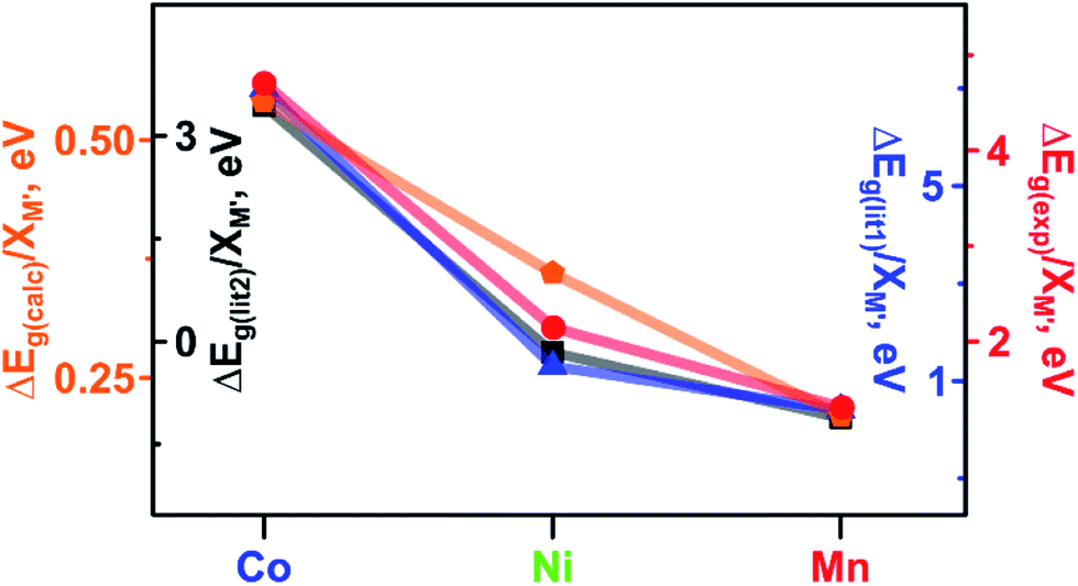 | ||
| Fig. 5 Band gaps: measured ΔEg(exp) (red circles) and calculated ΔEg(calc) (orange pentagons) for Cu3−XM′X(BTC)2 MOFs. Literature data: measured ΔEg(lit1) for M′5%:ZnO (dark blue triangles)40 and calculated ΔEg(lit2) for M′12.5%:TiO2 (black squares).41 ΔEg values have been normalized to the M′ metal mole fraction (M′ = Co, Ni, and Mn). | ||
As a part of our studies, we surveyed the electronic structure changes in heterometallic MM′-MOFs with the same M and M′ but with a different M to M′ ratio (Fig. 3a). The choice of metal ratios was a balance between incorporation of the highest percentage of the second metal, M′, and preservation of framework integrity. According to conductivity measurements, the largest difference in electronic properties within the same composition was observed for Cu3−XCoX(BTC)2 systems. Indeed, changes from 2% to 7% of incorporated cobalt according to ICP-MS analysis resulted in a five-fold conductivity enhancement (Fig. 3a and Table S10†). The statistical difference between measured conductivity values was probed by employment of a variance test (ANOVA) integrated in the MATLAB package.43–45 As a result, it was demonstrated that the conductivity values of the Cu3−XCoX(BTC)2 samples with different cobalt percentages are indeed statistically different. In the other heterometallic systems with the same M/M′ pairs, the experimentally observed changes as a function of M to M′ ratio were less pronounced in comparison with those observed for Cu3−XCoX(BTC)2. For instance, changes in iron percentage from 9 to 25% in Cu3−XFeX(BTC)2 do not lead to significant changes of electronic properties as shown by conductivity measurements (Fig. 3). Indeed, for Cu3−XFeX(BTC)2, the estimated p-value was greater than 0.05, and thus, the null hypothesis, that measured conductivity values are the same, could not be rejected. At the same time, the one-way analysis of variance performed for the Cu3−XMnX(BTC)2 system demonstrates that the measured conductivity values are statistically different.
Mononuclear heterometallic M3−XM′X(HHTP)2 frameworks
In contrast to three-dimensional BTC-systems, monometallic Cu3(HHTP)2 and Co9(HHTP)4 MOFs are two-dimensional frameworks with a relatively high intrinsic conductivity.30,46 Since metal nodes are mononuclear in M3−XM′X(HHTP)2, each M or M′ is separated from one another by an organic linker. However, presence of a second metal, M′ = Co, Ni, Mn, and Rh, in the Cu3−XM′X(HHTP)2 lattice still affects the material electronic profile. Similar to Cu3−XM′X(BTC)2, the main changes in the electronic structure of Cu3−XM′X(HHTP)2 appeared after cobalt incorporation.However, in contrast to BTC-frameworks, conductivity of heterometallic HHTP-MOFs decreases upon incorporation of a second metal in comparison with that of their monometallic analogues. We estimated the conductivity values as (2.10 ± 0.01) × 10−5 S × cm−1 for Cu2.5Co0.5-HHTP, (8.80 ± 0.09) × 10−6 S cm−1 for Cu2.0Mn1.0-HHTP, (9.90 ± 0.06) × 10−8 S cm−1 for Cu1.5Ni1.5-HHTP, and the lowest value was found to be (8.60 ± 0.02) × 10−9 S cm−1 for the Cu2.6Rh0.4-HHTP framework (Tables 2 and S10†); while conductivity measured under the same conditions for the parent Cu3(HHTP)2 framework was found to be (4.90 ± 0.02) × 10−4 S × cm−1 (Fig. 6a). Previous literature reports for similar 2D frameworks are in line with our studies.28,47 Thus, it was shown through theoretical modeling that the nickel-to-copper transmetallation procedure in M-HITP systems (HITP3− = 2,3,6,7,10,11-hexaaminotriphenylenesemiquinonate) possessing the same AAAA packing motif can result in changes of the framework electronic behavior from semiconducting to metallic due to different coordination environments adopted by nickel versus copper that likely leads to packing distortion.48 As we previously mentioned, Cu3(HHTP)2 possesses AAAA packing while layers of Co9(HHTP)4 alternate in the ABAB sequence.28 While the A layer in both frameworks consists of the M3(HHTP)2 two-dimensional honeycomb structure, the B layer in the case of Co9(HHTP)4 is formed by discrete Co3(HHTP) units resulting in a Co6(HHTP)2 layer (Fig. 6c).28 Therefore, we speculate that changes in electronic behavior of heterometallic HHTP-systems may be indicative of a structural distortion of the 2D sheets due to distinct coordination environments adopted by M and M′. PXRD analysis demonstrated that all Cu3−XM′X(HHTP)2 possess AAAA stacking that allows for comparison of electronic properties of bimetallic MOFs. To probe possible M′–property correlations similar to the BTC-system, we have evaluated |Δσ|/XM′ as shown in Fig. 6b. Although the unnormalized conductivity values (σ) decrease for Co < Mn < Ni < Rh, the corrected values |Δσ|/XM′ (σ* and σ = conductivity values for Cu3(HHTP)2 and Cu3−XM′X(HHTP)2, respectively) do not demonstrate M′–conductivity dependence (Fig. 6b). The optical data (Eg, Table 2) corroborated the trend observed for conductivity values, σ. The smallest band gap among all heterometallic HHTP-systems was detected after integration of Co (1.06 eV) and an increase in Eg values was observed for M′ = Mn (1.17 eV) < Ni (1.20 eV) < Rh (1.23 eV, Table S8†). However, adjustments based on the mole fraction of integrated metal by estimation of ΔEg/XM′ (Eg and Eg* = band gap values for Cu3(HHTP)2 and Cu3−XM′X(HHTP)2, respectively) did not result in the M′–Eg correlation similar to that observed for Cu3−XM′X(BTC)2 systems (Fig. 5).
 | ||
| Fig. 6 (a) A mononuclear metal node and graphical illustration of the results of conductivity measurements obtained for Cu3−XM′X(HHTP)2 as a function of M′ = Co, Mn, Ni, and Rh. (b) Changes in conductivity (|Δσ|, dark blue triangles), experimentally measured band gaps (ΔEg, red circles), and estimated valence band onset values from the XPS data (ΔE′, black squares) as a function of M′ performed for Cu3−XM′X(HHTP)2 (M′ = Co, Mn, Ni, and Rh). The ΔEg, ΔE′, and |Δσ| values have been normalized to the mole fraction of M′ (XM′). The corresponding graphs with error bars are shown in Fig. S37.† (c) Crystal structure of the Co-containing HHTP system possessing the bnn topology (shown in inset).28 The red, gray, and dark blue spheres represent O, C, and Co atoms, respectively. H atoms were omitted for clarity. | ||
The oxidation states for incorporated M′ = Mn, Ni, and Co inside the HTTP-systems coincide with the values observed for the BTC-systems. Indeed, XPS analysis of the Mn(2p), Ni(2p), and Co(2p) regions of both systems reveals the following oxidation states +2 (Mn), +2 (Ni), and +2 (Co) (see the ESI for more details, Fig. S28–S30†). Furthermore, analysis of the Rh(3d) region indicates the presence of rhodium in the +3 oxidation state (310 eV, Fig. S33†) for the HHTP system. According to XPS studies, the highest DOS near EF was detected for Cu3−XCoX(HHTP)2 and Cu3−XMnX(HHTP)2 based on the E′ values (Tables 2 and S6†). For other HHTP-systems where M′ = Ni (E′ = 1.38 eV for Cu3−XNiX(HHTP)2, Table S6†) and Rh (E′ = 1.51 eV for Cu3−XRhX(HHTP)2, Table S6†), the DOS near the Fermi edge are less pronounced (Fig. S40†). Overall, for the Cu3−XM′X(HHTP)2 system after incorporation of the first–row transition metals, E′ values vary in the range of 1.10–1.38 (eV) while for BTC-frameworks E′ changes from 1.50 eV (Zn) to 1.76 eV (Fe) with the exception of the Co-incorporated sample (E′ = 0.29 eV, Tables 2 and S6†). The larger E′ values are consistent with conductivity values, σ (Tables 2 and S10†), which demonstrate that HHTP-frameworks are in general more conductive than the BTC-systems. Similar to BTC-frameworks, we estimated (zM′ × XM′ and zCu × XCu) changes as a function of M′ in HHTP-systems (where zM′ (zCu) = charge on the metal (copper); XM′ (XCu) = mole fraction of M′ (Cu)). Similar to calculations performed for the BTC-systems (vide supra), the constant from eqn (2) was estimated to be 1.53 from the XPS spectrum of the monometallic Cu3(HHTP)2 sample.
The corresponding values of (zCu × XCu/zM′ × XM′) for incorporated Co, Mn, and Ni were found to be 1.19/0.33, 1.01/0.51, and 0.77/0.75, respectively (Table 2 and Fig. S39†).
Pentanuclear heterometallic M5−XM′X(NIP)4 frameworks
The choice of a M5(NIP)4 framework for our studies was based on several facts such as, it possesses a larger metal node ensemble size with nuclearity = 5, and therefore, the possibility of stronger metal–metal interactions and electron coupling.49,50 However, the pentanuclear metal cluster resulted in a significant complication for the second metal with the incorporation. Thus, the main challenge in the case of pentanuclear heterometallic Cu5−XM′X(NIP)4 systems was preservation of framework integrity after M′ integration. We were able to successfully incorporate Mn, Fe, and Rh inside the Cu5−XM′X(NIP)4 framework according to the ICP-MS analysis. The oxidation states for incorporated Mn and Rh were found to be +2 and +3, respectively, based on XPS data (Fig. S32 and S33†). Oxidation states of iron were not elucidated due to a low signal-to-noise ratio. However, despite the source of the cobalt (e.g., Co(NO3)2·6H2O, CoCl2·6H2O, or Co(OAc)2·4H2O) and a number of synthetic conditions, our attempts to integrate Co inside the Cu5(NIP)4 lattice resulted in amorphous powders that distinguish the NIP-systems from the previously discussed BTC- and HHTP-frameworks. The measured conductivity values are (4.30 ± 0.02) × 10−6 S × cm−1 (Cu4.8Mn0.2-NIP), (1.20 ± 0.01) × 10−7 S × cm−1 (Cu4.4Fe0.6-NIP), and (1.30 ± 0.04) × 10−8 S × cm−1 (Cu4.8Rh0.2-NIP, Fig. 7a). The estimated band gap values from the Tauc plot analysis were found to be 2.91 eV (Cu4.8Mn0.2-NIP), 2.76 eV (Cu4.4Fe0.6-NIP), and 3.53 eV (Cu4.8Rh0.2-NIP). Due to the small number of data points, which is a reflection of synthetic challenges and system complexity (Fig. 7b), we were not able to establish M′–property trends similar to those discussed for BTC-MOFs (Fig. 3). To overcome challenges in structure–property correlations, novel synthetic pathways for access and characterization of heterometallic frameworks with a different composition should be developed first.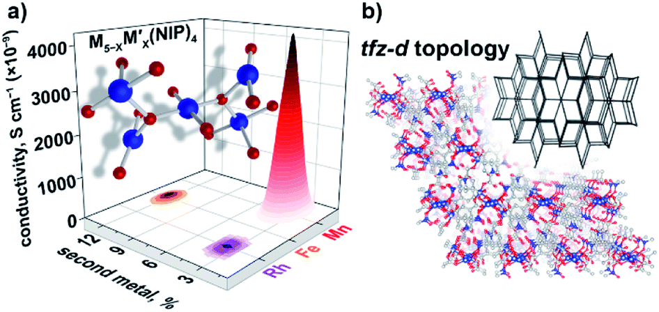 | ||
| Fig. 7 (a) A pentanuclear metal node and graphical illustration of the results of conductivity measurements obtained for Cu5−XM′X(NIP)4 as a function of M′ = Rh, Fe, and Mn. (b) Crystal structure of parent Cu5(NIP)4, possessing the tfz-d MOF topology (shown in inset).29 The red, gray, blue, and dark blue spheres represent O, C, N, and Cu atoms, respectively. H atoms were omitted for clarity. | ||
Conclusions
We probed the electronic profiles of MOFs containing mononuclear, binuclear, and pentanuclear metal nodes as a function of a second metal. For the example of the binuclear BTC-containing heterometallic frameworks, in which the incorporated transition metal (M′) belongs to the first-row, we established a correlation between the changes in the experimentally and theoretically estimated band gaps, ΔEg, calculated onset values of VB spectra, ΔE′, and conductivity values, |Δσ|. We find that Co-containing MOFs across all Cu3−XM′X(BTC)2 systems (M′ = Co, Ni, Fe, Mn, and Zn) possess the highest DOS near the Fermi level, which match the theoretically predicted and experimentally estimated band gap values. The origin of the DOS is also discussed according to the theoretical modeling results. In addition, a literature search revealed several similar trends observed previously for oxides doped with 3d metals. The results of Bader charge analysis and studies using the Voronoi–Dirichlet partition of crystal structures are also presented. The HHTP-system consisting of mononuclear nodes possesses higher conductivity in comparison with that of the BTC-samples; this behavior correlates with the smaller band gaps observed for HHTP-MOFs in comparison with those of the BTC-frameworks. The NIP-containing frameworks with pentanuclear metal nodes are the most complex and synthetically challenging among all MOFs studied. Our results for the NIP-frameworks demonstrate the need for both comprehensive analysis of the M′–property tendencies, and novel avenues for preparation of heterometallic multinuclear isoreticular structures. To summarize, the presented studies are the first steps toward understanding and developing the material landscape necessary for on-demand tailoring of electronic properties in heterometallic systems.Conflicts of interest
There are no conflicts to declare.Acknowledgements
N. B. S. and D. A. C. are grateful for support from the U.S. Department of Energy, Office of Science and Office of Basic Energy Sciences under Award DE-SC0019360. N. B. S. acknowledges the support from the Sloan Research Fellowship provided by Alfred P. Sloan Foundation and Camille Dreyfus Teaching-Scholar Award provided by Henry and Camille Dreyfus Foundation. S. R. P., S. P., and N. B. S. acknowledge support from the Energy Frontier Research Center funded by the U.S. Department of Energy, Office of Science under Award DE-SC0016574. In addition, we thank the University of South Carolina Advanced Support for Innovative Research Excellence program. S. G. acknowledges partial support from the National Science Foundation EPSCoR Program under NSF Award OIA-1655740/20-GC03.Notes and references
- G. Skorupskii and M. Dincă, J. Am. Chem. Soc., 2020, 142, 6920–6924 CrossRef CAS PubMed.
- J. Li, X. Yu, M. Xu, W. Liu, E. Sandraz, H. Lan, J. Wang and S. M. Cohen, J. Am. Chem. Soc., 2017, 139, 611–614 CrossRef CAS PubMed.
- D. M. Shakya, O. A. Ejegbavwo, T. Rajeshkumar, S. D. Senanayake, A. J. Brandt, S. Farzandh, N. Acharya, A. M. Ebrahim, A. I. Frenkel, N. Rui, G. L. Tate, J. R. Monnier, K. D. Vogiatzis, N. B. Shustova and D. A. Chen, Angew. Chem., Int. Ed., 2019, 58, 16533–16537 CrossRef CAS PubMed.
- T. A. Goetjen, X. Zhang, J. Liu, J. T. Hupp and O. K. Farha, ACS Sustainable Chem. Eng., 2019, 7, 2553–2557 CrossRef CAS.
- J. Liu, Z. Li, X. Zhang, K.-I. Otake, L. Zhang, A. W. Peters, M. J. Young, N. M. Bedford, S. P. Letourneau, D. J. Mandia, J. W. Elam, O. K. Farha and J. T. Hupp, ACS Catal., 2019, 9, 3198–3207 CrossRef CAS.
- Y. Huang, Y. Sun, X. Zheng, T. Aoki, B. Pattengale, J. Huang, X. He, W. Bian, S. Younan, N. Williams, J. Hu, J. Ge, N. Pu, X. Yan, X. Pan, L. Zhang, Y. Wei and J. Gu, Nat. Commun., 2019, 10, 982 CrossRef CAS PubMed.
- S. Yang, B. Pattengale, S. Lee and J. Huang, ACS Energy Lett., 2018, 3, 532–539 CrossRef CAS.
- D. J. Xiao, J. Oktawiec, P. J. Milner and J. R. Long, J. Am. Chem. Soc., 2016, 138, 14371–14379 CrossRef CAS PubMed.
- W. Liu, W. P. Lustig and J. Li, EnergyChem, 2019, 1, 100008 CrossRef.
- M. Bornstein, D. M. Parker, A. D. Quast, J. S. Shumaker-Parry and I. Zharov, ChemCatChem, 2019, 11, 4360–4367 CrossRef CAS.
- A. D. Quast, M. Bornstein, B. J. Greydanus, I. Zharov and J. S. Shumaker-Parry, ACS Catal., 2016, 6, 4729–4738 CrossRef CAS.
- M. J. Neufeld, J. L. Harding and M. M. Reynolds, ACS Appl. Mater. Interfaces, 2015, 7, 26742–26750 CrossRef CAS PubMed.
- A. M. Rice, G. A. Leith, O. A. Ejegbavwo, E. A. Dolgopolova and N. B. Shustova, ACS Energy Lett., 2019, 4, 1938–1946 CrossRef CAS.
- L. Sun, C. H. Hendon, S. S. Park, Y. Tulchinsky, R. Wan, F. Wang, A. Walsh and M. Dincă, Chem. Sci., 2017, 8, 4450–4457 RSC.
- L. Sun, C. H. Hendon, S. S. Park, Y. Tulchinsky, R. Wan, F. Wang, A. Walsh and M. Dincă, Chem. Sci., 2017, 8, 4450–4457 RSC.
- K. C. Bentz and S. M. Cohen, Angew. Chem., Int. Ed., 2018, 57, 14992–15001 CrossRef CAS PubMed.
- Z. Chen, S. L. Hanna, L. R. Redfern, D. Alezi, T. Islamoglu and O. K. Farha, Coord. Chem. Rev., 2019, 386, 32–49 CrossRef CAS.
- X. Zhao, M. S. Shimazu, X. Chen, X. Bu and P. Feng, Angew. Chem., Int. Ed., 2018, 57, 6208–6211 CrossRef CAS PubMed.
- Y. Liao, L. Zhang, M. H. Weston, W. Morris, J. T. Hupp and O. K. Farha, Chem. Commun., 2017, 53, 9376–9379 RSC.
- H. Wang, X. Dong, J. Lin, S. J. Teat, S. Jensen, J. Cure, E. V. Alexandrov, Q. Xia, K. Tan, Q. Wang, D. H. Olson, D. M. Proserpio, Y. J. Chabal, T. Thonhauser, J. Sun, Y. Han and J. Li, Nat. Commun., 2018, 9, 1745 CrossRef PubMed.
- N. R. Catarineu, A. Schoedel, P. Urban, M. B. Morla, C. A. Trickett and O. M. Yaghi, J. Am. Chem. Soc., 2016, 138, 10826–10829 CrossRef CAS PubMed.
- M. J. Kalmutzki, N. Hanikel and O. M. Yaghi, Sci. Adv., 2018, 4, eaat9180 CrossRef CAS PubMed.
- L. S. Xie, L. Sun, R. Wan, S. S. Park, J. A. DeGayner, C. H. Hendon and M. Dincă, J. Am. Chem. Soc., 2018, 140, 7411–7414 CrossRef CAS PubMed.
- Q. G. Zhai, X. Bu, C. Mao, X. Zhao and P. Feng, J. Am. Chem. Soc., 2016, 138, 2524–2527 CrossRef CAS PubMed.
- J. G. Park, M. L. Aubrey, J. Oktawiec, K. Chakarawet, L. E. Darago, F. Grandjean, G. J. Long and J. R. Long, J. Am. Chem. Soc., 2018, 140, 8526–8534 CrossRef CAS PubMed.
- S. Yuan, J.-S. Qin, H.-Q. Xu, J. Su, D. Rossi, Y. Chen, L. Zhang, C. Lollar, Q. Wang, H.-L. Jiang, D. H. Son, H. Xu, Z. Huang, X. Zou and H.-C. Zhou, ACS Cent. Sci., 2018, 4, 105–111 CrossRef CAS PubMed.
- S. Yuan, J.-S. Qin, J. Su, B. Li, J. Li, W. Chen, H. F. Drake, P. Zhang, D. Yuan, J. Zuo and H.-C. Zhou, Angew. Chem., Int. Ed., 2018, 57, 12578–12583 CrossRef CAS PubMed.
- M. Hmadeh, Z. Lu, Z. Liu, F. Gándara, H. Furukawa, S. Wan, V. Augustyn, R. Chang, L. Liao, F. Zhou, E. Perre, V. Ozolins, K. Suenaga, X. Duan, B. Dunn, Y. Yamamto, O. Terasaki and O. M. Yaghi, Chem. Mater., 2012, 24, 3511–3513 CrossRef CAS.
- Y. Zhao, M. Padmanabhan, Q. Gong, N. Tsumori, Q. Xu and J. Li, Chem. Commun., 2011, 47, 6377–6379 RSC.
- M. Ko, A. Aykanat, M. K. Smith and K. A. Mirica, Sensors, 2017, 17, 2192 CrossRef PubMed.
- S. S.-Y. Chui, S. M.-F. Lo, J. P. H. Charmant, A. G. Orpen and I. D. Williams, Science, 1999, 283, 1148–1150 CrossRef CAS PubMed.
- V. A. Blatov and V. N. Serezhkin, Russ. J. Inorg. Chem., 2000, 45, S105−S222 Search PubMed.
- V. A. Blatov, A. P. Shevchenko and D. M. Proserpio, Cryst. Growth Des., 2014, 14, 3576–3586 CrossRef CAS.
- E. A. Dolgopolova, A. J. Brandt, O. A. Ejegbavwo, A. S. Duke, T. D. Maddumapatabandi, R. P. Galhenage, B. W. Larson, O. G. Reid, S. C. Ammal, A. Heyden, M. Chandrashekhar, V. Stavila, D. A. Chen and N. B. Shustova, J. Am. Chem. Soc., 2017, 139, 5201–5209 CrossRef CAS PubMed.
- O. A. Ejegbavwo, C. R. Martin, O. A. Olorunfemi, G. A. Leith, R. T. Ly, A. M. Rice, E. A. Dolgopolova, M. D. Smith, S. G. Karakalos, N. Birkner, B. A. Powell, S. Pandey, R. J. Koch, S. T. Misture, H.-C. zur Loye, S. R. Phillpot, K. S. Brinkman and N. B. Shustova, J. Am. Chem. Soc., 2019, 141, 11628–11640 CrossRef CAS PubMed.
- A. S. Duke, E. A. Dolgopolova, R. P. Galhenage, S. C. Ammal, A. Heyden, M. D. Smith, D. A. Chen and N. B. Shustova, J. Phys. Chem. C, 2015, 119, 27457–27466 CrossRef CAS.
- G. Kresse and J. Hafner, Phys. Rev. B: Condens. Matter Mater. Phys., 1993, 47, 558–561 CrossRef CAS PubMed.
- G. Kresse and J. Furthmüller, Phys. Rev. B: Condens. Matter Mater. Phys., 1996, 54, 11169–11186 CrossRef CAS PubMed.
- A. D. Becke, J. Chem. Phys., 1993, 98, 5648–5652 CrossRef CAS.
- S. V. Bhat and F. L. Deepak, Solid State Commun., 2005, 135, 345–347 CrossRef CAS.
- Y. Wang, R. Zhang, J. Li, L. Li and S. Lin, Nanoscale Res. Lett., 2014, 9, 46 CrossRef PubMed.
- K. J. Kim and Y. R. Park, Appl. Phys. Lett., 2002, 81, 1420–1422 CrossRef CAS.
- H.-S. Oh, Biometrics, 2013, 69, 1086–1089 CrossRef.
- D. B. Rorabacher, Anal. Chem., 1991, 63, 139–146 CrossRef CAS.
- R. F. Hirsch, Anal. Chem., 1977, 49, 691A–700A CrossRef CAS.
- L. Mendecki and K. A. Mirica, ACS Appl. Mater. Interfaces, 2018, 10, 19248–19257 CrossRef CAS PubMed.
- M. K. Smith and K. A. Mirica, J. Am. Chem. Soc., 2017, 139, 16759–16767 CrossRef CAS PubMed.
- S. Chen, J. Dai and X. C. Zeng, Phys. Chem. Chem. Phys., 2015, 17, 5954–5958 RSC.
- F. Karsai, M. Engel, E. Flage-Larsen and G. Kresse, New J. Phys., 2018, 20, 123008 CrossRef CAS.
- M. Muthukrishnaveni and N. Srinivasan, Phase Transitions, 2015, 88, 1174–1180 CrossRef CAS.
Footnotes |
| † Electronic supplementary information (ESI) available. CCDC 2001459–2001464. For ESI and crystallographic data in CIF or other electronic format see DOI: 10.1039/d0sc03053h |
| ‡ These authors contributed equally. |
| This journal is © The Royal Society of Chemistry 2020 |